

Page 1

ERC-Mini V1.3 Manual
___________________________________________________________________________
© Ing.-Büro E. Alba de Schmidt Page 1 of 16 web : www.schmidt-alba.de
Kreuzangerstr. 58 20151114 email : erc@schmidt-alba.de
86399 Bobingen / Germany
This document is for the user only. Any publishing (printed or in electronic form) is not allowed.
Manual
Congratulations for buying your EASY-ROTOR-CONTROL Mini (shortly ERC-Mini).
This document will guide you through the needed steps for installation, configuration
and calibration of the ERC-M Mini. You will reach the best result by following these
instructions step by step.
Table of contents
Safety-Instructions ................................................................................................................. 2
1. Description ......................................................................................................................... 2
2. ERC-Mini for Yaesu/Kenpro SDX .................................................................................... 3
2.1 Bill of material (BOM) ................................................................................................. 3
2.2 Mechanical Installation ................................................................................................ 3
3. ERC-Mini for Yaesu/Kenpro DXA/DXC, Create, Emotator ............................................. 5
3.1 Bill of material (BOM) for Yaesu/Kenpro DXA/DXC ................................................ 5
3.2 Bill of material (BOM) for Create -P ........................................................................... 5
3.3 Bill of material (BOM) for Emotator ........................................................................... 5
3.4 Connection of ERC-Mini to the control-box ................................................................ 5
4. Establishing the USB-connection ....................................................................................... 6
5. The Service-Tool for Windows .......................................................................................... 6
5.1 Configuration of the COM-Port ................................................................................... 7
5.2 Read the ERC-MINI-configuration-parameters ........................................................... 7
5.3 Language ...................................................................................................................... 7
5.4 Speed-control ............................................................................................................... 7
5.5 Calibration .................................................................................................................... 8
5.6 Other functions of the Service Tool ............................................................................. 9
6. First check of calibration with Rotor-Control G ................................................................ 9
7. Connection of ERC-Mini to other programs ...................................................................... 9
Appendices ........................................................................................................................... 10
Appendix 1: Specification ................................................................................................ 10
Appendix 2: Schematics ERC-Mini ................................................................................. 11
Appendix 3: Assembly-plan ERC-Mini ........................................................................... 12
Appendix 4: Rotor-protocol command-set ....................................................................... 13
Appendix 5: API (application programming interface) ................................................... 14
Appendix 6: Rotor-connections ....................................................................................... 16
Page 2

ERC-Mini V1.3 Manual
___________________________________________________________________________
© Ing.-Büro E. Alba de Schmidt Page 2 of 16 web : www.schmidt-alba.de
Kreuzangerstr. 58 20151114 email : erc@schmidt-alba.de
86399 Bobingen / Germany
This document is for the user only. Any publishing (printed or in electronic form) is not allowed.
Safety-Instructions
• Don’t continue using the product if it is damaged.
• Keep electronic assemblies and components away from children!
• Products that carry electric voltages must be handled by taking care about the
valid instructions and regulations.
• If the product must be repaired, only use original spare parts! Using different parts
may cause property damage and personal injury! The repair has only to be done
by an expert!
• The installation has to be done by a skilled expert.
• Connection-cables have to be chosen according to the needed diameter.
• Before working on the product all supply-voltages have to be securely cut of.
• The product is designed to work in clean and dry areas inside buildings.
• Prevent the product of humidity, water and heat.
• Don’t use the product in areas where explosive gases, vapour or dust are or may
occur.
• Don’t let the product fall or apply mechanical stress as the product may be
damaged.
1. Description
ERC-Mini is a computer-interface designed to connect various Rotators of the manufacturers Yaesu,
Kenpro, Create and Emotator to a computer.
- Yaesu/Kenpro: models ending with DXA/DXC
- Yaesu/Kenpro: models ending with SDX
- Create: models ending with –P with a 6-pin DIN remote-connector
- Emotator: models with a 5-pin DIN remote connecting socket
On The computer-side it provides an USB-interface and a build-in COM/serial-interface with a FTDIchip to provide a virtual-comport on any Windows,MacOS or Linux-machine.
On the rotor-control-box-side it can be easily connected to the control-box with the cable that came
with your interface or, in case of Yaesu/Kenpro SDX, can be easily mounted inside the control-box and
fixed with 2 screws.
All further technical information can be retrieved from the appendices in this manual.
Page 3
ERC-Mini V1.3 Manual
___________________________________________________________________________
© Ing.-Büro E. Alba de Schmidt Page 3 of 16 web : www.schmidt-alba.de
Kreuzangerstr. 58 20151114 email : erc@schmidt-alba.de
86399 Bobingen / Germany
This document is for the user only. Any publishing (printed or in electronic form) is not allowed.
2. ERC-Mini for Yaesu/Kenpro SDX
2.1 Bill of material (BOM)
ERC-Mini SDX V1.3 Bill Of Material
QTY Type Value Reference Comments
1 PCB assembled ERC-Mini SDX V1.3
2 Distance-bolts M3x6x8
3 Screws M3x6
2 Spring-washers 3.2mm
1 Strain-relief 4mm for USB-cable
1 USB-cable A to B 1.8m
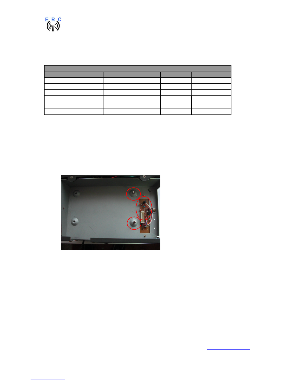
2.2 Mechanical Installation
For the mechanical integration of the ERC-Mini SDX please go ahead like this:
- unplug the SDX-control-box from its main-supply and the rotor-cable
- open the cabinet of the SDX-control-box by removing the 2 screws on the side of the cabinet
and the 4 screws on the bottom of the cabinet that also hold the rubber-feet
- mount the 2 distance-bolts M3x6x8 as shown in the next picture and slightly bend the
components that may conflict with the ERC-Mini SDX-PCB
Page 4
ERC-Mini V1.3 Manual
___________________________________________________________________________
© Ing.-Büro E. Alba de Schmidt Page 4 of 16 web : www.schmidt-alba.de
Kreuzangerstr. 58 20151114 email : erc@schmidt-alba.de
86399 Bobingen / Germany
This document is for the user only. Any publishing (printed or in electronic form) is not allowed.
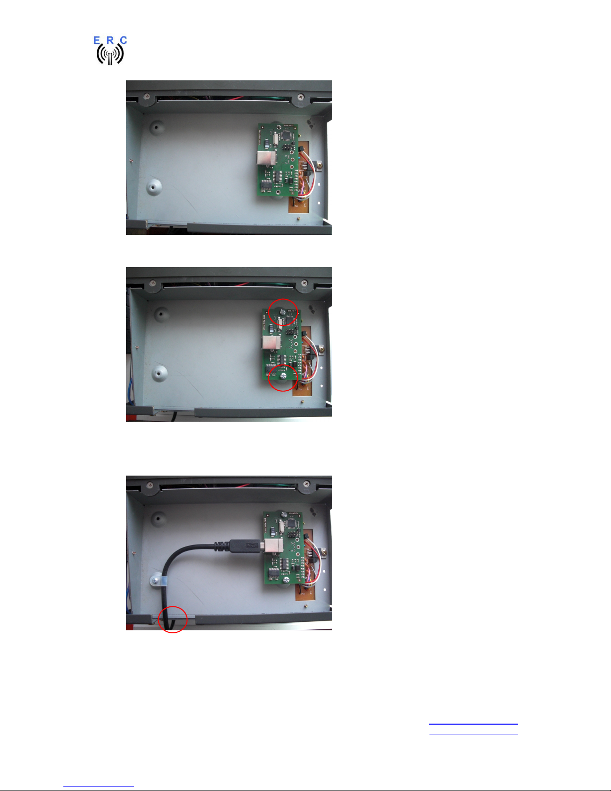
- plug the ERC-Mini SDX into the 8-pin-pinheader as shown in the next picture
- fix the ERC-Mini SDX with 2 screws M3x6 and 2 spring-washers 3.2mm as shown in the next
picture
- connect the USB-B-connector to the ERC Mini SDX and let the USB-cable exit on the back-
side of the cabinet
- fix the USB-cable with the strain-relief as shown in the next picture
- close again the cabinet with the 6 screws and the 4 rubber-feet you removed before
- connect the rotor-cable and the main-supply
Page 5
ERC-Mini V1.3 Manual
___________________________________________________________________________
© Ing.-Büro E. Alba de Schmidt Page 5 of 16 web : www.schmidt-alba.de
Kreuzangerstr. 58 20151114 email : erc@schmidt-alba.de
86399 Bobingen / Germany
This document is for the user only. Any publishing (printed or in electronic form) is not allowed.
3. ERC-Mini for Yaesu/Kenpro DXA/DXC, Create, Emotator
3.1 Bill of material (BOM) for Yaesu/Kenpro DXA/DXC
ERC-Mini V1.3 DX Bill Of Material
QTY Type Value Reference Comments
1 Interface ERC-Mini V1.3 In enclosure
1 Cable to control-box Mini-DIN6 – Mini-DIN6 2m
1 USB-cable A to B 1.8m
3.2 Bill of material (BOM) for Create -P
ERC-Mini V1.3 -P
QTY Type Value Reference Comments
1 Interface ERC-Mini V1.3 In enclosure
1 Cable to control-box Mini-DIN6 – DIN6 1m
1 USB-cable A to B 1.8m
3.3 Bill of material (BOM) for Emotator
ERC-Mini V1.3 EMO Bill Of Material
QTY Type Value Reference Comments
1 Interface ERC-Mini V1.3 In enclosure
1 Cable to control-box Mini-DIN6 – DIN5 1m
1 USB-cable A to B 1.8m
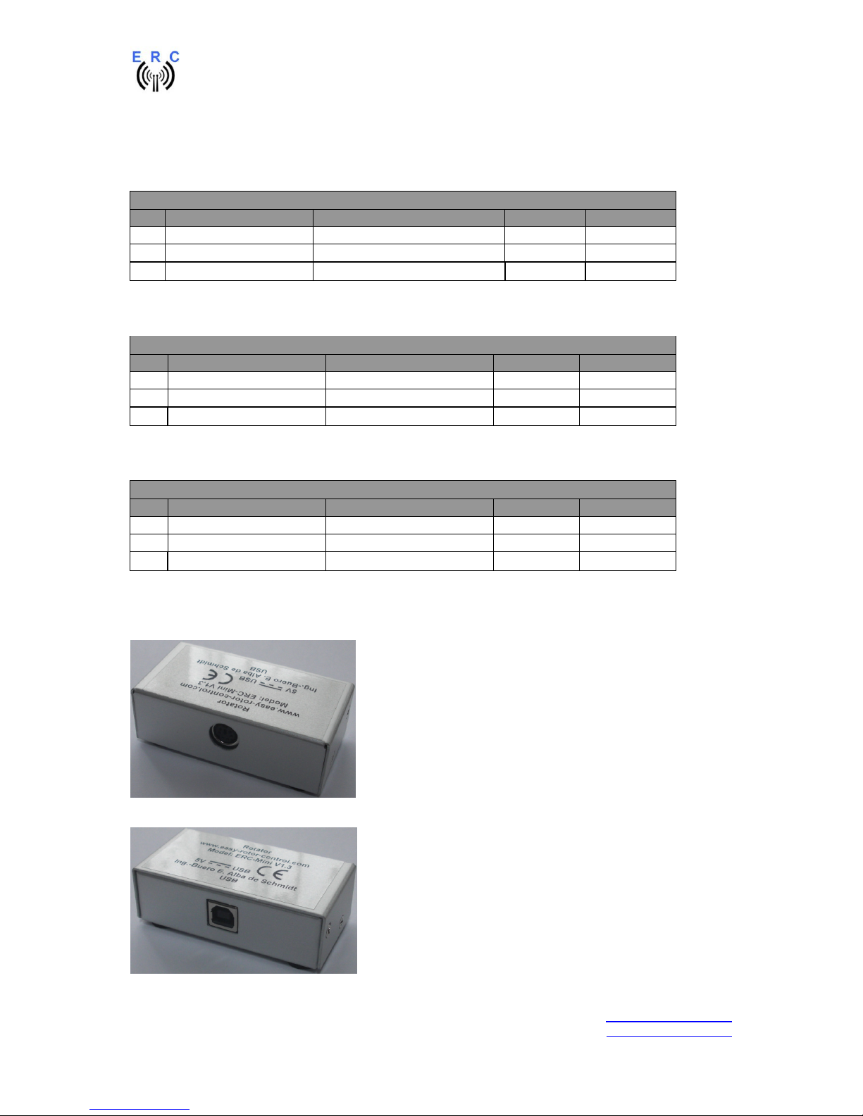
3.4 Connection of ERC-Mini to the control-box
Plug the cable with the Mini-DIN6 into the ERC-Mini and the other side into the control-box.
Plug the USB-cable with the USB-B-connector into the ERC-Mini.
Page 6
ERC-Mini V1.3 Manual
___________________________________________________________________________
© Ing.-Büro E. Alba de Schmidt Page 6 of 16 web : www.schmidt-alba.de
Kreuzangerstr. 58 20151114 email : erc@schmidt-alba.de
86399 Bobingen / Germany
This document is for the user only. Any publishing (printed or in electronic form) is not allowed.
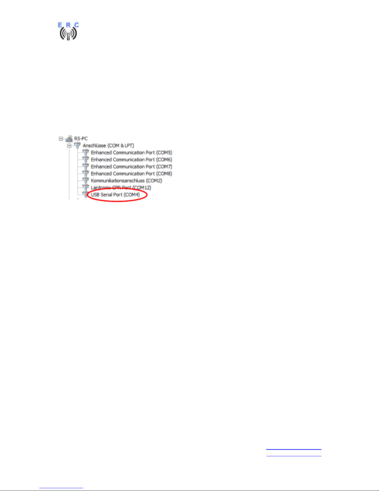
4. Establishing the USB-connection
Plug the USB-A-connector to a free USB-connector on your computer.
Depending on your operating-system, you will be asked to install an USB-driver. This driver is
available in the Drivers-folder on the CD delivered with your ERC-Mini.
After successful installation of the driver, a new COM-Port (COMn) is available. You can identify the
COM-port-number by inspecting the hardware-settings of your computer. In case you have a conflict
with another COM-port (e.g. virtual COM-port), change the COM-port-number in the properties.
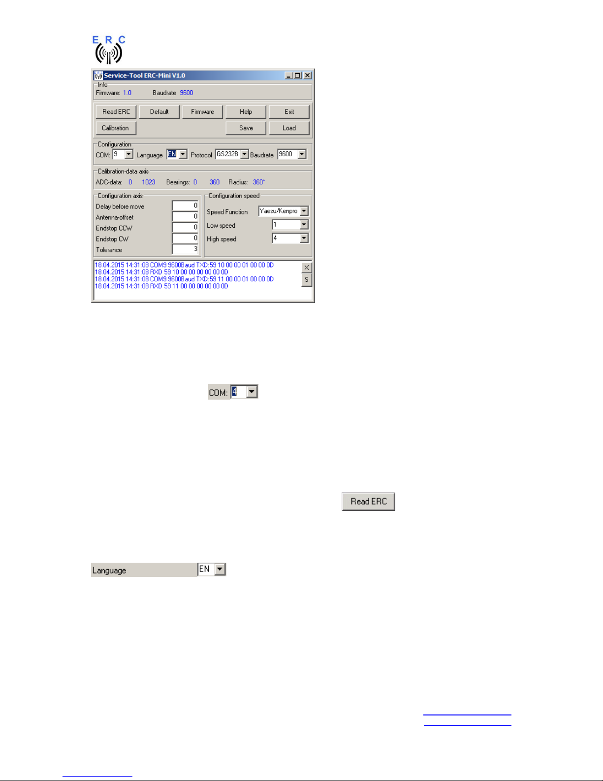
5. The Service-Tool for Windows
If you use another OS than Windows (e.g. MacOS or Linux), please read the appendix 5 for calibration
and configuration of the ERC-Mini.
The Service Tool is on the CD supplied with the kit.
Start the Setup-File SETUP ERC-Mini_Vnn.EXE (nn=version) directly on the CD and follow the
instructions.
The installation-wizard will automatically install the Service Tool in the program directory (or any other
if you choose a different one) and put an icon on your desktop.
Start the Service Tool by double-clicking the Icon on the desktop.
Page 7
ERC-Mini V1.3 Manual
___________________________________________________________________________
© Ing.-Büro E. Alba de Schmidt Page 7 of 16 web : www.schmidt-alba.de
Kreuzangerstr. 58 20151114 email : erc@schmidt-alba.de
86399 Bobingen / Germany
This document is for the user only. Any publishing (printed or in electronic form) is not allowed.
5.1 Configuration of the COM-Port
On shipment, the Service Tool is configured to COM1, which is most properly not the com-port, which
was assigned to the ERC-Mini by the hardware-manager of your computer, hence after Start-Up the
program may bring up an error-message because of the wrong COM-Port.
Choose the right COM-Port.
The Service Tool will check the availability of the ERC-Mini at the chosen COM-Port. If successful, the
Service Tool will read the configuration-parameters of the ERC-Mini and populates the configurationand the calibration-panels.
5.2 Read the ERC-MINI-configuration-parameters
The parameters of the ERC-MINI can be read by clicking the button.
5.3 Language
The Service-Tool and the help-files are available in different languages. Choose the language with the
-box.
5.4 Speed-control
ERC-Mini provides an automatic speed-control like this:
- rotator starts moving with low-speed
- after 30° the rotator speeds up to high-speed
- 30° prior to reaching the target-position, rotator will again slow down to low speed.
Page 8

ERC-Mini V1.3 Manual
___________________________________________________________________________
© Ing.-Büro E. Alba de Schmidt Page 8 of 16 web : www.schmidt-alba.de
Kreuzangerstr. 58 20151114 email : erc@schmidt-alba.de
86399 Bobingen / Germany
This document is for the user only. Any publishing (printed or in electronic form) is not allowed.
This takes away stress from the whole structure, especially with large antenna-arrays or heavy
antennas.
The rotators from Create Yaesu-Kenpro allow the speed-control in 4 stages:1 - 2 - 3 – 4, where 1 is
the lowest speed and 4 is the highest speed
Speed-Function
Possible values: none – Yaesu/Kenpro - Create
- choose Yaesu/Kenpro for their rotator-series DXA/DXC and SDX
- choose Create for their rotator-models ending with –P
- choose none for Emotator (no Speed-Control)
Low speed (only available if Yaesu/Kenpro has been choosen)
possible values: 1 / 2
- configured to 1: low speed will be performed with speed 1
- configured to 2: low speed will be performed with speed 2
High speed (only available if Yaesu/Kenpro has been choosen)
possible values: 3 / 4
- configured to 3: high speed will be performed with speed 3
- configured to 4: high speed will be performed with speed 4
5.5 Calibration
After the ERC-Mini is connected to the computer, it has to be calibrated. This calibration is a one-timetask and the result of calibration will be stored inside the ERC-Mini.
To calibrate the ERC-Mini, it has to measure the rotor-feedback-voltages at both ends including a
possible overlap (turning radius > 360°). The calibration is a software-guided procedure, which will be
started by pressing the button of the service tool.
Just follow the instructions given by the calibration assistant and for questions, read the Calibrationsection of the help-file available through the Help-button of the Service-Tool.
Page 9

ERC-Mini V1.3 Manual
___________________________________________________________________________
© Ing.-Büro E. Alba de Schmidt Page 9 of 16 web : www.schmidt-alba.de
Kreuzangerstr. 58 20151114 email : erc@schmidt-alba.de
86399 Bobingen / Germany
This document is for the user only. Any publishing (printed or in electronic form) is not allowed.
5.6 Other functions of the Service Tool
The other functions of the Service Tool and the other configuration-items are well described in the
help-function of the Service Tool. Click the button.
6. First check of calibration with Rotor-Control G
The rotor-control-program Rotor-Control G is on the CD supplied with your interface.
Set the ERC-Mini with the Service-Tool to Baudrate 9600 and Protocol GS232B and than close the
Service-Tool..
Start the Setup-File SETUP RC-G_Vnn.EXE directly on the CD and follow the instructions.
The installation wizard will automatically install Rotor-Control G in the program directory (or any other
if you choose a different one) and puts an icon on your desktop.
Start Rotor-Control G by double-clicking the Icon on the desktop.
The green pointer and number show the current position of the rotator.
A target can be put at the red number and rotation starts by clicking the the GO-button.You can stop
the rotation any time by clicking the STOP-button.
You can also move the rotator to a target-position by clicking on any point of the graphic.
By clicking the button PARK, the rotator moves to the configured parking position.
7. Connection of ERC-Mini to other programs
Please take care about the following issues, if you want to control your ERC-Mini with other programs:
- Choose the right COM-port
- COM-port-speed (baudrate) in the program must be same as in ERC-Mini
o The speed of ERC-Mini is shown in the service-tool
- Adjust the comport in the program to: N-8-1 (No Parity, 8 databits,1 stopbit)
- Use the same protocol in program and ERC-Mini (Yaesu GS232B, GS232A or Hygain DCU-1)
o The protocol of ERC-Mini is shown the service-tool
Page 10

ERC-Mini V1.3 Manual
___________________________________________________________________________
© Ing.-Büro E. Alba de Schmidt Page 10 of 16 web : www.schmidt-alba.de
Kreuzangerstr. 58 20151114 email : erc@schmidt-alba.de
86399 Bobingen / Germany
This document is for the user only. Any publishing (printed or in electronic form) is not allowed.
Appendices
Appendix 1: Specification
ERC-Mini specification
Mechanical Dimensions
- PCB: 67mm x 37,5mm
- Enclosure: 78mm x 40mm x 24mm
DC Supply
- USB-powered 5VDC
- current consumption: max 10mA
Temperature-range
- 0°C to 70°C
Measurement input circuits (rotor feedback voltage)
- range : 0 to 6V against ground
- input-impedance : > 25KOhm
- protected against high voltage bursts coming through the cable
- measurement-resolution: 10 Bit
Outputs
- CW, CCW: Open collector-outputs against ground
- max. current per open-collector-output with 2 outputs simultaneously at 100% duty-cycle and 70° C: 380mA
- Speed: 4 stage DAC with high-Impedance output-voltages of 0,6V to 4,7V
Communication-interface
- USB through type B connector
- USB/serial converter with FTDI-chip
Controller
- 8-bit RISC-architecture
- bootloader to update firmware through USB
- supported protocols for rotor-control
o subset of Yaesu GS232A / GS232B
o subset of Hygain DCU-1 and extensions for position feedback
Firmware supported features
- delay before rotator starts moving
- programmable end stops
- antenna offset
- support of overlap up to 180°
- speed-function
- tolerance of position
- software-calibration
- security stop if rotor doesn´t move
- configurable communication-speed: 4800 -9600 Baud
- save and load of all calibration- and configuration-data
Service-Tool and Rotor-Control G
- Supported operating systems
o Windows 2000 and XP
o Windows Vista, 7, 8, 10 (32 bit and 64 bit)
Page 11
ERC-Mini V1.3 Manual
___________________________________________________________________________
© Ing.-Büro E. Alba de Schmidt Page 11 of 16 web : www.schmidt-alba.de
Kreuzangerstr. 58 20151114 email : erc@schmidt-alba.de
86399 Bobingen / Germany
This document is for the user only. Any publishing (printed or in electronic form) is not allowed.
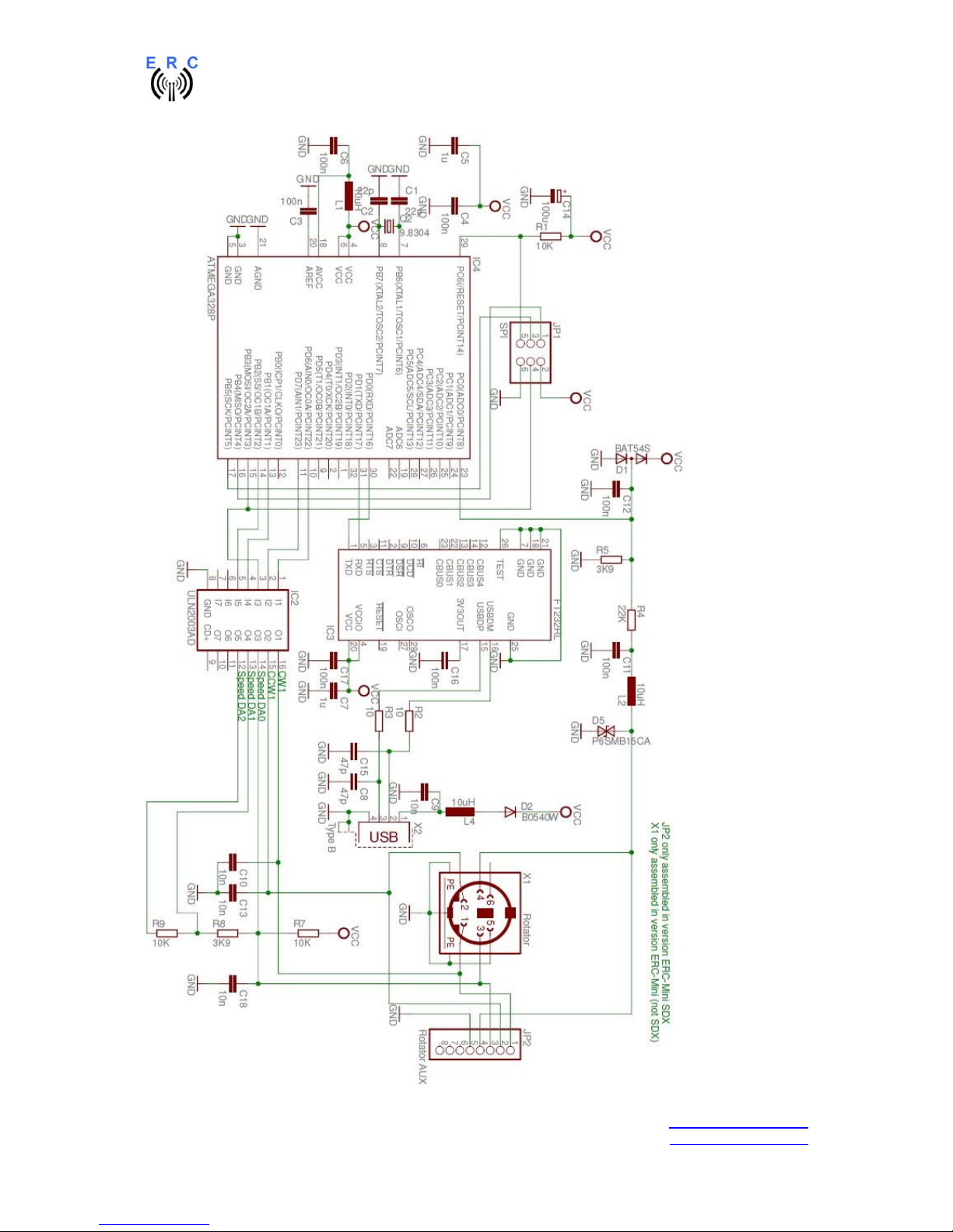
Appendix 2: Schematics ERC-Mini
Page 12

ERC-Mini V1.3 Manual
___________________________________________________________________________
© Ing.-Büro E. Alba de Schmidt Page 12 of 16 web : www.schmidt-alba.de
Kreuzangerstr. 58 20151114 email : erc@schmidt-alba.de
86399 Bobingen / Germany
This document is for the user only. Any publishing (printed or in electronic form) is not allowed.
Appendix 3: Assembly-plan ERC-Mini
Page 13

ERC-Mini V1.3 Manual
___________________________________________________________________________
© Ing.-Büro E. Alba de Schmidt Page 13 of 16 web : www.schmidt-alba.de
Kreuzangerstr. 58 20151114 email : erc@schmidt-alba.de
86399 Bobingen / Germany
This document is for the user only. Any publishing (printed or in electronic form) is not allowed.
Appendix 4: Rotor-protocol command-set
Remarks for the annotation in this document:
<cr> = carriage return and represent the decimal-value 13 = Hex-value 0Dh
<lf> = line feed and represents the decimal-value 10 = Hex-value 0Ah
aaa = a 3-digit azimuth-position with leading 0
eee = a 3-digit elevation-position with leading 0
<s> = space and represents the decimal-value 32 = Hex-value 20h
Whenever this document refers to elevation, setting a position will be ignored and if a position is
requested for elevation it always returns 000.
Hygain DCU-1 with extensions for position-request
Some commands are redundant with slight differences to keep compatibility to the different
implementations of the DCU-1-protocol in different programs
Command to ERC
-
Mini Description
Returned from ERC
-
Mini
AS1; Stop rotation
AI1;<cr> Request position azimuth ;aaa
AI1; Request position azimuth ;aaa
AM1;<cr> Execute rotation
AM1; Execute rotation
AP1aaa;<cr> Set azimuth-position to aaa
AP1aaa; Set azimuth-position to aaa
D Rotate CCW
MGaaa Rotate azimuth to aaa
U Rotate CW
; Stop rotation
Yaesu GS232 A and B
The only difference in A and B is the format how a position is returned from the ERC
Command to ERC
Description
Returned from ERC
A<cr> Stop rotation azimuth <cr>
C<cr> (in GS232A-mode) Request position azimuth +0aaa<cr><lf>
C<cr> (in GS232B-mode) Request position azimuth AZ=aaa<cr><lf>
C2<cr> (in GS232A-mode) Request position azimuth + elevation +0aaa+0eee<cr><lf>
C2<cr> (in GS232B-mode) Request position azimuth + elevation AZ=aaa<s><s>EL=eee<cr><lf>
L<cr> Rotate CCW 1st axis <cr>
Maaa<cr> Rotate azimuth to aaa <cr>
R<cr> Rotate CW 1st axis <cr>
S<cr> Stops rotation <cr>
Waaa<s>eee<cr> Rotate azimuth to aaa and Rotate elevation to
eee
<cr>
Page 14

ERC-Mini V1.3 Manual
___________________________________________________________________________
© Ing.-Büro E. Alba de Schmidt Page 14 of 16 web : www.schmidt-alba.de
Kreuzangerstr. 58 20151114 email : erc@schmidt-alba.de
86399 Bobingen / Germany
This document is for the user only. Any publishing (printed or in electronic form) is not allowed.
Appendix 5: API (application programming interface)
If another OS than Windows is used (e.g. MacOS or Linux), the Service-Tool that came with your
ERC-Mini is of no use.
In order to perform configuration- and calibration-tasks, ERC-Mini provides a programming-interface,
which can be easily used with a terminal-program.
Remarks for the annotation in this document:
<cr> = carriage return and represent the Ascii-code 13 = Hex-code 0D
Start the terminal-program, set the right COM-port and the communication-speed (default speed is
9600 Baud)
These are the commands provided by the API:
Commands to read the settings of the ERC-Mini:
Commands to configure and calibrate the ERC-Mini:
Page 15

ERC-Mini V1.3 Manual
___________________________________________________________________________
© Ing.-Büro E. Alba de Schmidt Page 15 of 16 web : www.schmidt-alba.de
Kreuzangerstr. 58 20151114 email : erc@schmidt-alba.de
86399 Bobingen / Germany
This document is for the user only. Any publishing (printed or in electronic form) is not allowed.
Programming examples
(Keep in mind, that every command must be terminated with a carriage-return which is hex 0Dh or
decimal 13)
- Example for calibration:
o Situation: your rotator has an overlap of 90° and is moving clockwise
180° – 270° – 360° – 90° – 180° - 270°
o Move your rotator manually to the most counter-clockwise position at 180°
Send to ERC-Mini: sCAL0180
o Move your rotator manually to the most clockwise position at 270°
Send to ERC-Mini: sCAR0270
o The result of calibration can be read back from the ERC-Mini like this:
Send to ERC-Mini: rANR
ERC-Mini answers: aANR0270
Send to ERC-Mini: rANL
ERC-Mini answers: aANL0180
Send to ERC-Mini: rCAR
ERC-Mini answers: aCAR0711 (0711 is the ADC-value at 270° CW)
Send to ERC-Mini: rCAL
ERC-Mini answers: aCAR0004 (0004 is the ADC-value at 180° CCW)
- Example for setting the delay before move to 2000 milliseconds = 2 seconds:
Send to ERC-Mini: sDBM2000
o The result of setting can be read back from the ERC-Mini like this:
Send to ERC-Mini: rDBM
ERC-Mini answers: aDBM2000
If a command to ERC-Mini is wrong or a value is out of range an error is reported from ERC-Mini
- If an incorrect read-command was received, ERC-Mini sends: r-ERROR
- If an incorrect set-command was received, ERC-Mini sends: s-ERROR
Page 16
ERC-Mini V1.3 Manual
___________________________________________________________________________
© Ing.-Büro E. Alba de Schmidt Page 16 of 16 web : www.schmidt-alba.de
Kreuzangerstr. 58 20151114 email : erc@schmidt-alba.de
86399 Bobingen / Germany
This document is for the user only. Any publishing (printed or in electronic form) is not allowed.
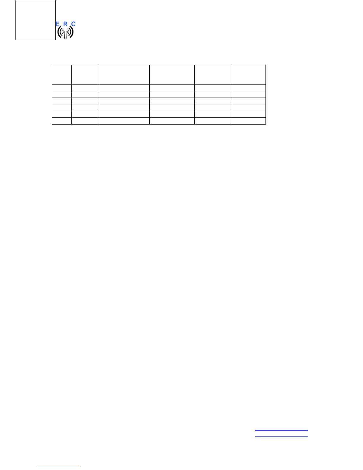
Appendix 6: Rotor-connections
ERCMini
Function Yaesu/Kenpro
SDX
8-pole pinheader
Yaesu/Kenpro
DXA/DXC
6-pole Mini-DIN
Create
RC5x-3-P
6-pole DIN
Emotator
5-pole DIN
1 CW 1 1 2 2
2 CCW 2 2 5 5
3 Speed 3 3 6 4 Position 4 4 1 1
5 GND 5 5 Shield Shield
6 - - - - -
 Loading...