

Page 1
1 2
Page 2
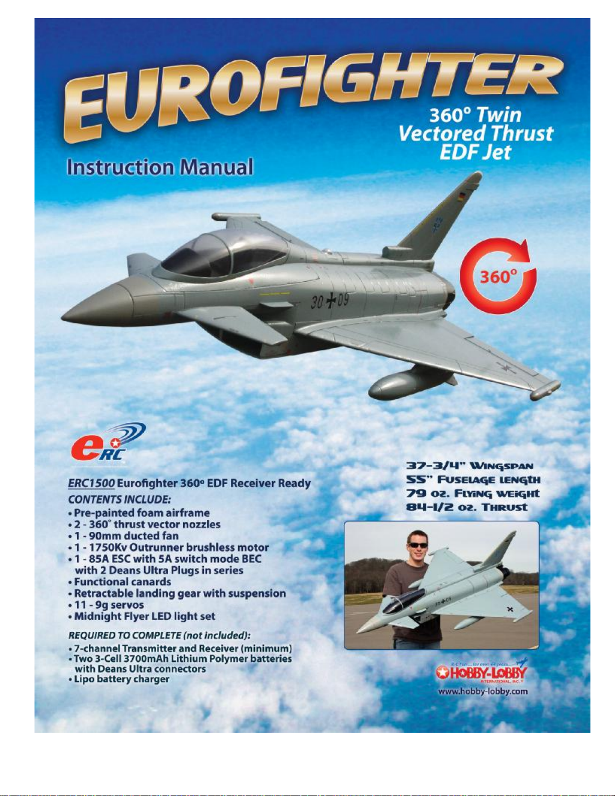
Hobby-Lobby is pleased to announce the eRC Eurofighter “Typhoon” 90mm EDF, the
first RC EDF jet in its class to include scale retractable landing gear with suspension,
working canards, 360 degree thrust vectoring nozzles and working position lights. A
great deal of the assembly is pre-done for you. This is a receiver ready jet that only
requires some simple assembly and the installation of the flight batteries and
programming of your radio equipment to be ready to fly. Please read the assembly
manual carefully to familiarize you with all the steps before starting.
Hobby Lobby International, Inc.
5614 Franklin Pike Circle
Brentwood, TN 37027
1-866-WE-FLY-RC
(1-866-933-5972)
www.hobby-lobby.com
Page 3
Before starting, use the contents list to take an inventory and make sure it is complete.
If any parts are missing or are not of acceptable quality, contact Hobby-Lobby.com
support at 1-866-WE-FLY-RC (1-866-933-5972)
Contents List
¨ Fuselage
¨ Canopy Battery Hatch
¨ Retractable Main Landing Gear and Wheels
¨ Retractable Nose Wheel and Gear Door (pre-installed)
¨ Brushless Outrunner Motor installed in 90mm Fan (pre-installed)
¨ 85A Speed Control w/5A Switch Mode BEC and Genuine Deans Ultra Conns
¨ Wings with Navigation lights (pre-installed)
¨ Vertical Tail with Navigation Light (pre-installed)
¨ Functional Canards
¨ Dual 360 Degree Thrust Vectoring Nozzles (pre-installed)
Additional Items Required
¨ 7-channel Aircraft Radio w/ Receiver (minimum), Computer radio recommended.
¨ Two 3-cell, 11.1V 3700mAh Lipo Batteries with Deans Ultra Connectors
¨ Dedicated Lithium Battery Charger (Balance Charger Recommended)
¨ 5-minute Epoxy Glue
¨ Small Phillips Screwdriver
¨ Needle Nose Pliers and Hobby Knife
3
Page 4

1. This manual will help you assemble your
Eurofighter Typhoon. Let’s start with the
installation of the main wing panels.
Apply an even coat of 5-minute epoxy to
the root of the wing panel.
2. Press into position on the fuselage side.
3. Check the alignment of the wing with the
fuselage and wipe off any epoxy that
squeezes out. A small amount of rubbing
alcohol on a paper towel works well.
4. Make sure to check the alignment on the
top of the wing to fuselage joint and wipe
off any excess epoxy. Hold in position
until the epoxy sets. Repeat this process
for the other main wing. We recommend
that you epoxy one panel at a time.
4
Page 5
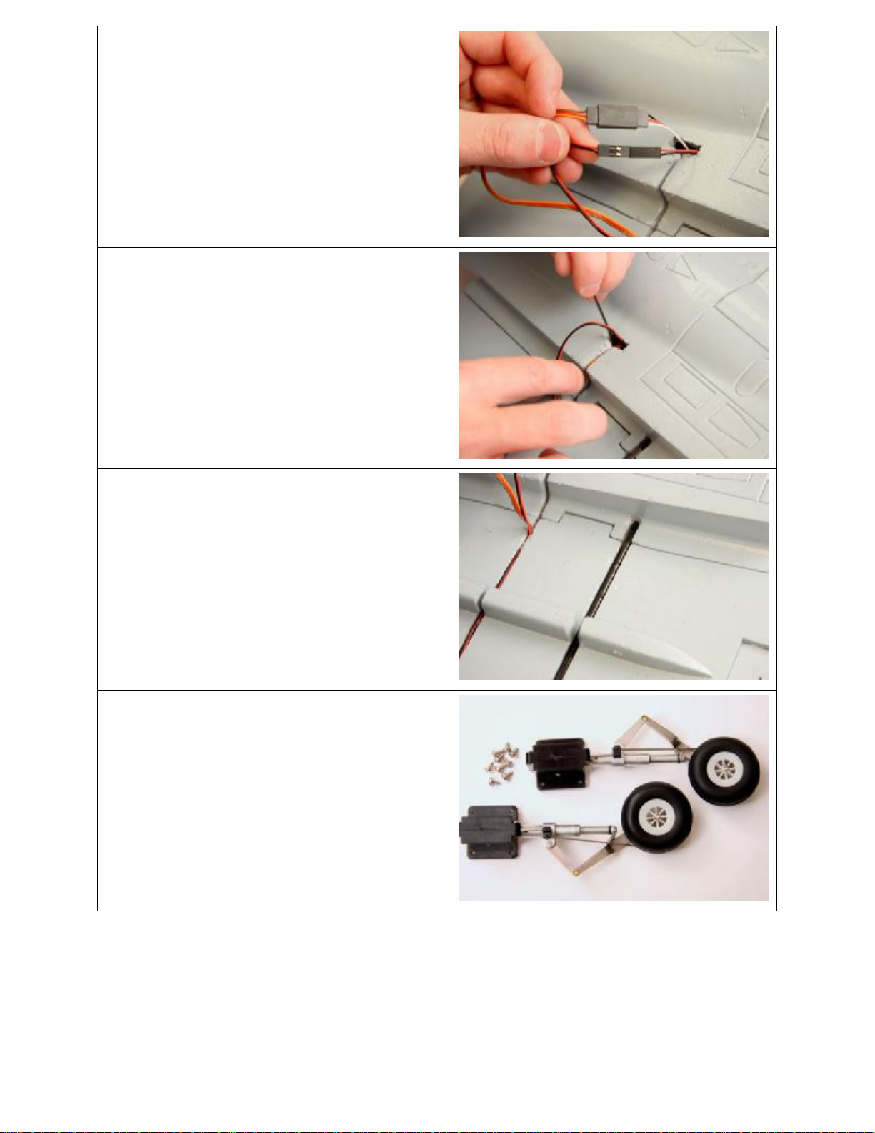
5. Plug in the Elevon servo and the wing tip
light. Please match the polarity. On the
servo connection, the orange wire
matches with the white wire on the plug
that exits the fuselage.
6. Feed the connected plugs into the
fuselage and carefully push the wires into
the slot in the wing and fuselage.
7. Locate the carbon rod wing reinforcement
and epoxy it in place in the groove on the
bottom of the wing panel.
8. Locate the 2 main landing gear units and
the 8 mounting screws.
5
Page 6
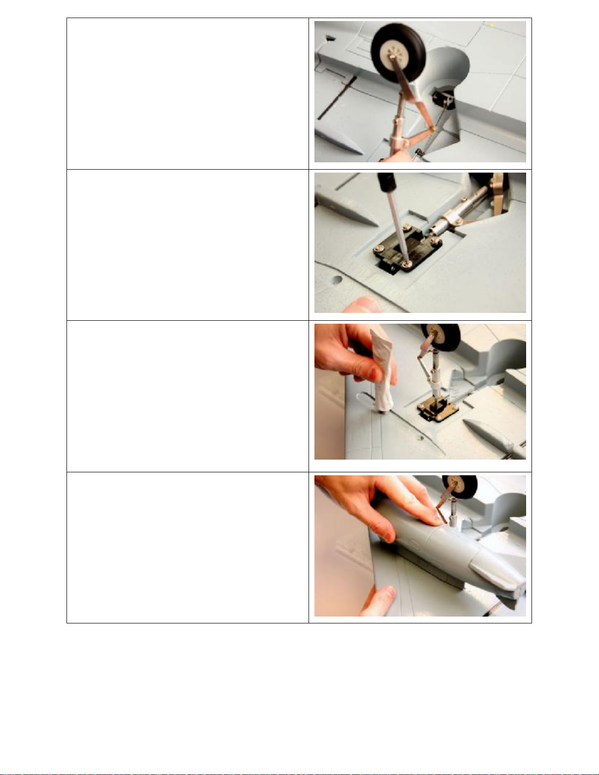
9. Insert the pushrod wire into the retract
servo as you fit the retract into position
on the wing.
10. Screw the retract into position.
11. Using foam glue or epoxy, apply glue to
the groove for the drop tanks.
12. Position each drop tank and allow the
glue to set.
6
Page 7

13. Turn the aircraft right side up on its gear.
Locate the vertical fin and plug in the
position light making sure that you match
the polarity (red-to-red and black-toblack)
14. Apply epoxy to the mating surfaces.
15. Push the vertical tail into position and
check for any glue that may have
squeezed out. Wipe off any excess with a
paper towel and a little rubbing alcohol.
16. Epoxy the nose cone in position.
7
Page 8

17. Locate the canards.
18. Insert canard into tube on side of
fuselage.
19. . Slip the nut onto the shaft inside the
fuselage. The nut works as a spacer. Slip
the control arm onto the shaft with the
control arm pointing down. Snug the
mounting screw to the flat on the metal
shaft.
20. Attach the canard pushrods to the servos
as shown. Make sure that your servos
are in their neutral position.
8
Page 9

21. Connect your 7-channel receiver to the
servo wires at the rear of the cockpit
opening. These connections are labeled.
22. Left Aileron and Left Vector = Aileron
23. Right Aileron and Right Vector = Elevator
24. Left Canard = Aux 1 (Flap)
25. Right Canard = Aux 2
26. Left/Right Thrust Vector and Nose Wheel
Steering = Rudder
27. Retracts = Landing Gear
28. Throttle = Throttle
29. The battery installs under the canopy and
is held in place with the pre-installed
hook and loop fasteners.
30. Use two 3-cell 3700mAh packs and plug
one each into the two Series Deans
connectors.
31. If you are using a single 6s battery you
will need to make a jumper from a female
Deans Ultra connector in order to make a
complete circuit.
32. Canopy hatch attaches first at the rear
and is held in place by magnets at the
front.
33. A 7-channel computer radio is required
to fly the Eurofighter. The following
instructions are for the Spektrum DX-7
transmitter with the Spektrum AR7000
receiver.
34. From the INPUT SELECT screen, inhibit
AUX2 and FLAP.
9
Page 10

35. From the WING TYPE screen, activate
DELTA so that it reads ON
36. In the D/R SWITCH SELECT screen
select COM ELEV. This sets all the
control surfaces dual rates onto the
elevator D/R switch.
37. The image to the right shows the
positions for servo reversing. Select
REVERSING SW from the radio menu
and set channels, 2, 3 and 5 to reverse
(REV). All other channels will be in the
NORM position.
38. From the D/R & EXPO screen, select the
AILE function. Set the dual rate switch for
the ailerons to the “0” POSITION. Set the
EXPO for +30 % to make the elevons
less responsive in roll around the stick
center. Set the D/R to 50%.
10
Page 11

39. From the D/R & EXPO screen, select the
AILE function. Set the dual rate switch for
the ailerons to the “1” POSITION. Set the
EXPO for +40 % to make the elevons
less responsive in roll around the stick
center. Set the D/R to 100%.
40. From the D/R & EXPO screen, select the
ELEV function. Set the dual rate switch
for the elevator to the “0” POSITION. Set
the EXPO for +30 % to make the elevons
less responsive in pitch around the stick
center. Set the D/R to 50%.
41. From the D/R & EXPO screen, select the
ELEV function. Set the dual rate switch
for the elevator to the “1” POSITION. Set
the EXPO for +40 % to make the elevons
less responsive in pitch around the stick
center. Set the D/R to 100%.
42. From the D/R & EXPO screen, select the
RUDD function. Set the dual rate switch
for the elevator to the “0” POSITION. Set
the EXPO for +20 % to make the rudder
less responsive around the stick center.
Set the D/R to 60%.
11
Page 12

43. From the D/R & EXPO screen, select the
RUDD function. Set the dual rate switch
for the elevator to the “1” POSITION. Set
the EXPO for +25 % to make the rudder
less responsive around the stick center.
Set the D/R to 100%.
44. Select PROG.MIX1 from the radio menu.
Set the mix for AILE to FLAP. Make sure
that the rates are both at -100% and that
the switch is set to MIX. There should be
no offset for this mix.
45. Select PROG.MIX2 from the radio menu.
Set the mix for AILE to AUX2. Make sure
that the rates are both at -100% and that
the switch is set to MIX. There should be
no offset for this mix.
46. Select PROG.MIX3 from the radio menu.
Set the mix for ELEV to FLAP. Make
sure that the rates are both at -100% and
that the switch is set to ON. There should
be no offset for this mix.
12
Page 13

47. Select PROG.MIX4 from the radio menu.
Set the mix for ELEV to AUX2. Make
sure that the rates are both at +100% and
that the switch is set to ON. There should
be no offset for this mix.
48. On LOW RATES the Elevons should
move 3/4" in both directions. The Thrust
Vector units should move in the same
direction as the Elevons.
NOTE: When the Elevons are in their neutral
position the Thrust Vector Nozzles should be
in their neutral position also. If they are not
you must adjust them mechanically by
screwing or unscrewing the ball link
connector to achieve a neutral position.
49. On HIGH RATES the Elevons should
move 1-1/2" in both directions. The
Thrust Vector units should move in the
same direction as the Elevons.
50. On LOW RATES the Canards should
move 5/8" in both directions. When the
Elevon moves UP the Leading edge of
the Canard should move UP.
13
Page 14

51. On HIGH RATES the Canards should
move 1-1/8" in both directions.
52. Neutral position of control surfaces.
53. When UP ELEVATOR is applied the
surfaces should look like this.
54. When DOWN ELEVATOR is applied the
surfaces should look like this.
14
Page 15

55. When RIGHT AILERON is applied the
surfaces should look like this.
The trailing edge of the right elevon and
the right canard should go up.
56. When LEFT AILERON is applied the
surfaces should look like this.
The trailing edge of the left elevon and
left canard should go up.
55. The Center of Gravity (CG) is measured
from the lip of the intake on the bottom of
the fuselage. Measure back 11-1/8”. This
is an all-around good CG location; you
may adjust this to your own flying style
after initial test flights.
Midnight Flyers LED Position Lights
Your Eurofighter Typhoon is equipped with 7 pre-installed high intensity LED’s. An
experienced R/C flyer that is comfortable with the Eurofighter can actually fly the jet in
the dark with the supplied lights.
Recommended Control Throws
Elevons Low Rate 3/4" Up and Down
High Rate 1-1/2" Up and Down
Canards Low Rate 5/8" Up and Down
High Rate 1-1/8" Up and Down
Center of Gravity 11-1/8" Back from the lip of the intake on bottom of fuselage
Preflight
15
Page 16

1. Aircraft assembled correctly and ready for flight.
2. All control throws and expos are set per this manual.
3. Transmitter fully charged and on correct model.
4. Aircraft balances at the recommended location.
5. Flight batteries are fully charged and secure.
6. All controls are operating correctly, proper direction, and secure.
7. Complete a radio range check per your radio manual.
8. Wait for a calm or light wind day for first flights.
Flying
We recommend that takeoffs and landings be made on LOW RATES. Initial flights
should be made using LOW RATES until you are familiar with the aircraft. LOW RATES
allow you to fly smooth pattern maneuvers. The jet is very stable with solid handling. On
HIGH RATES with the functioning Canards and Thrust Vectoring turned on, the airplane
can perform amazing maneuvers. High Alpha Harrier flight is easy to steer using the
thrust vector nozzles as your elevator and rudder controls. Flat spins are easily
accomplished using full rudder and up elevator combined with a bit of opposite aileron.
Example: Full left rudder, full up elevator and some right aileron to perform a left flat
spin. Exit the maneuver by neutralizing the elevator and aileron and applying slight right
rudder. This is a larger size model and requires the use of a scale type landing
approach. Set up your final approach with a slight nose high angle of attack and about
1/4 throttle, allow the jet to settle applying a little throttle to arrest the descent and touch
down on the main gear first. Ground handling is superior.
2008 Official Academy of Model Aeronautics National Model Aircraft Safety Code
GENERAL
1. A model aircraft shall be defined as a non-human-carrying device capable of sustained flight in the atmosphere. It shall
not exceed limitations established in this code and is intended to be used exclusively for recreational or competition
activity.
2. The maximum takeoff weight of a model aircraft, including fuel, is 55 pounds, except for those flown under the AMA
Experimental Aircraft Rules.
3. I will abide by this Safety Code and all rules established for the flying site I use. I will not willfully fly my model aircraft in a
reckless and/or dangerous manner.
4. I will not fly my model aircraft in sanctioned events, air shows, or model demonstrations until it has been proven airworthy.
5. I will not fly my model aircraft higher than approximately 400 feet above ground level, when within three (3) miles of an
airport without notifying the airport operator. I will yield the right-of-way and avoid flying in the proximity of full-scale
aircraft, utilizing a spotter when appropriate.
6. I will not fly my model aircraft unless it is identified with my name and address, or AMA number, inside or affixed to the
outside of the model aircraft. This does not apply to model aircraft flown indoors.
7. I will not operate model aircraft with metal-blade propellers or with gaseous boosts (other than air), nor will I operate
model aircraft with fuels containing tetranitromethane or hydrazine.
8. I will not operate model aircraft carrying pyrotechnic devices, which explode, burn, or propel a projectile of any kind.
Exceptions include Free Flight fuses or devices that burn producing smoke and are securely attached to the model aircraft
during flight. Rocket motors up to a G-series size may be used, provided they remain firmly attached to the model aircraft
during flight. Model rockets may be flown in accordance with the National Model Rocketry Safety Code; however, they
may not be launched from model aircraft. Officially designated AMA Air Show Teams (AST) are authorized to use devices
and practices as defined within the Air Show Advisory Committee Document.
9. I will not operate my model aircraft while under the influence of alcohol or within eight (8) hours of having consumed
alcohol.
10. I will not operate my model aircraft while using any drug which could adversely affect my ability to safely control my model
aircraft.
11. Children under six (6) years old are only allowed on a flightline or in a flight area as a pilot or while under flight instruction.
12. When and where required by rule, helmets must be properly worn and fastened. They must be OSHA, DOT, ANSI,
SNELL or NOCSAE approved or comply with comparable standards.
RADIO CONTROL
1. All model flying shall be conducted in a manner to avoid over flight of unprotected people.
16
Page 17

2. I will have completed a successful radio equipment ground-range check before the first flight of a new or repaired model
aircraft.
3. I will not fly my model aircraft in the presence of spectators until I become a proficient flier, unless I am assisted by an
experienced pilot.
4. At all flying sites a line must be established, in front of which all flying takes place. Only personnel associated with flying
the model aircraft are allowed at or in front of the line. In the case of airshows demonstrations straight line must be
established. An area away from the line must be maintained for spectators. Intentional flying behind the line is prohibited.
5. I will operate my model aircraft using only radio-control frequencies currently allowed by the Federal Communications
Commission (FCC). Only individuals properly licensed by the FCC are authorized to operate equipment on Amateur Band
frequencies.
6. I will not knowingly operate my model aircraft within three (3) miles of any preexisting flying site without a frequencymanagement agreement. A frequency management agreement may be an
allocation of frequencies for each site, a day-use agreement between sites, or testing which determines that no
interference exists. A frequency-management agreement may exist between two or more AMA chartered clubs, AMA
clubs and individual AMA members, or individual AMA members. Frequency-management agreements, including an
interference test report if the agreement indicates no interference exists, will be signed by all parties and copies provided
to AMA Headquarters.
7. With the exception of events flown under official AMA rules, no powered model may be flown outdoors closer than 25 feet
to any individual, except for the pilot and located at the flightline.
8. Under no circumstances may a pilot or other person touch a model aircraft in flight while it is still under power, except to
divert it from striking an individual.
9. Radio-controlled night flying is limited to low-performance model aircraft (less than 100 mph). The model aircraft must be
equipped with a lighting system which clearly defines the aircraft's attitude and direction at all times.
10. The operator of a radio-controlled model aircraft shall control it during the entire flight, maintaining visual contact without
enhancement other than by corrective lenses that are prescribed for the pilot. No model aircraft shall be equipped with
devices which allow it to be flown to a selected location which is beyond the visual range of the pilot.
WARNING – THIS IS NOT A TOY! Radio controlled model aircraft are capable of inflicting serious injury and/or property damage if
not assembled, operated, and maintained in a competent and safe manner. If you are not already experienced with radio controlled
models, we strongly suggest that you find an experienced modeler to assist you.
Hobby-Lobby guarantees this kit to be free from defects in both material and workmanship at the date of purchase. This warranty
does not cover any component parts damaged by use or modification. In no event shall Hobby-Lobby’s liability exceed the original
Completely read through this manual before starting construction.
Warranty
cost of the purchased kit.
Hobby Lobby International, Inc.
5614 Franklin Pike Circle
Brentwood, TN 37027
1-866-WE-FLY-RC
(1-866-933-5972)
www.hobby-lobby.com
Rev V1.2 on 3/11/10
Corrected steps 44-45, 55-56
Rev V1.3 on 3/12/10
Corrected steps 38-43
17
 Loading...