

Page 1

EASY-ROTOR-CONTROL M V2.2 Instructions
Instructions
Congratulations for buying your EASY-ROTOR-CONTROL M (shortly ERC-M). This
document will guide you through the needed steps for assembly and configuration of
the ERC-M. You will reach the best result by following these instructions step by step.
Table of contents
Safety-Instructions ................................................................................................................. 2
1. ERC-M USB ...................................................................................................................... 3
1.1 Bill of material (BOM)................................................................................................. 3
1.2 Preparation of USB-modul........................................................................................... 4
1.3 Assembly of the ERC-M USB PCB............................................................................. 4
1.4 Connection of the DC-supply and check of the voltage-regulator............................... 8
1.5 Insert ICs and the USB-module ................................................................................... 9
1.6 Establishing the USB-connection................................................................................. 9
2. ERC-M RS232 ................................................................................................................. 10
2.1 Bill of material (BOM)............................................................................................... 10
2.2 Assembly of RS232 cable .......................................................................................... 11
2.3 Assembly of the ERC-M RS232 PCB........................................................................ 12
2.4 Connection of the DC-supply and check of the voltage-regulator............................. 16
2.5 Insert ICs .................................................................................................................... 17
3. LAN-Interface (optional) ................................................................................................. 18
3.1 Bill of material ........................................................................................................... 18
3.2 Assembly of the LAN-Interface................................................................................. 18
3.4 Check of the DC/DC-converter.................................................................................. 20
3.5 Device-Installer .......................................................................................................... 21
3.6 Installation of the COM-Port-Redirector (CPR) ........................................................ 21
4. Rotor-Card (optional)....................................................................................................... 23
4.1 Bill of material ........................................................................................................... 23
4.2 Assembly of the Rotor-Card PCB.............................................................................. 23
4.3 Connection of the Rotor-Card .................................................................................... 25
4.4 Test of Rotor-Card ..................................................................................................... 26
4.5 Installation of the Rotor-Card into a control-box....................................................... 26
5. SlimLine housing (optional)............................................................................................. 28
6. HID AZ/AZ or AZ/EL and desktop housing (optional)................................................... 29
6.1 Bill of material ........................................................................................................... 29
6.2 Assembly of bottom-side HID-PCB .......................................................................... 30
6.3 Assembly of top-side HID-PCB AZ/AZ (dual azimuth) ........................................... 31
6.4 Assembly of top-side HID-PCB AZ/EL (azimuth&elevation) .................................. 33
6.5 Cable to connect the HID to ERC-M ......................................................................... 35
6.6 Cable to connect the ERC-M to rear-side D-SUB ..................................................... 35
6.7 Mechanical integration into the desktop-housing ...................................................... 36
7. The Service-Tool.............................................................................................................. 38
7.1 Configuration of the COM-Port ................................................................................. 38
___________________________________________________________________________
© Ing.-Büro E. Alba de Schmidt web : www.schmidt-alba.de
Tannenstr. 16 Page 1 of 44 email : erc@schmidt-alba.de
86836 Untermeitingen / Germany
This document is for the user only. Any publishing (printed or in electronic form) is not allowed.
Page 2
EASY-ROTOR-CONTROL M V2.2 Instructions
7.2 Read the ERC-M-configuration-parameters .............................................................. 38
7.3 Language .................................................................................................................... 38
7.4 Other functions of the Service Tool ........................................................................... 38
8. Theory of operation.......................................................................................................... 39
9. Calibration........................................................................................................................ 39
10. First check of calibration with Rotor-Control M ........................................................... 39
11. Connect the ERC-M to other programs.......................................................................... 40
Appendix .............................................................................................................................. 41
Appendix1: Pin-out of D-SUB15 ERC-M ....................................................................... 41
Appendix2: Pin-out of mini-DIN rotor-card .................................................................... 41
Appendix3: Connection of rotor-card to ERC-M ............................................................ 41
Appendix4: Pin-out of the HID-connector on ERC-M .................................................... 42
Appendix5: Schematics Rotor-Card................................................................................. 42
Appendix6: Schematics ERC-M ...................................................................................... 43
Appendix7: Schematics HID............................................................................................ 44
Safety-Instructions
• Don’t continue using the product if it is damaged.
• Keep electronic assemblies and components away from children!
• Products that carry electric voltages must be handled by taking care about the
valid instructions and regulations.
• If the product must be repaired, only use original spare parts! Using different parts
may cause property damage and personal injury! The repair has only to be done
by an expert!
• The installation has to be done by a skilled expert.
• Connection-cables have to be chosen according to the needed diameter.
• Before working on the product all supply-voltages have to be securely cut of.
• The product is designed to work in clean and dry areas inside buildings.
• Prevent the product of humidity, water and heat.
• Don’t use the product in areas where explosive gases, vapour or dust are or may
occur.
• Don’t let the product fall or apply mechanical stress as the product may be
damaged.
___________________________________________________________________________
© Ing.-Büro E. Alba de Schmidt web : www.schmidt-alba.de
Tannenstr. 16 Page 2 of 44 email : erc@schmidt-alba.de
86836 Untermeitingen / Germany
This document is for the user only. Any publishing (printed or in electronic form) is not allowed.
Page 3
EASY-ROTOR-CONTROL M V2.2 Instructions
1. ERC-M USB
If your kit is RS232 (not USB) go to chapter 2.
1.1 Bill of material (BOM)
The BOM is in the order how you should use the parts.
ERC-M USB V2.2 Bill Of Material
QTY Type Value Reference Comments
1 USB-module FTDI IC3
1 Pinheader 1x8 pole precision for USB-Module
1 PCB ERC-M 2-layer 80x65mm V2.2
C3,C4,C6,C9,C10,
9 Capacitor ceramic 100n 50V 20%
1 Capacitor ceramic 10n 50V 20% C21
1 Crystal 9.8304 MHz HC49U Q1
2 IC-socket 16 pole DIL16 for IC2,IC3
1 IC-socket 28 pole DIL28 for IC1
2 Capacitor ceramic 22p 16V 5% C1,C2
2 Capacitor tantal 1u 35V 20% C7,C8
1 Mini-fuse 1.0A F1
2 Transistor BC557 T1,T2 alt. BC558,BC559
1 Voltage-regulator 78L05 TO92 IC4
2 Resistor 4K7 5% R10,R11 alt. 4K7 1%
4 Resistor 20K 5% R2,R3,R6,R7 alt. 20K 1%
2 Resistor 39K 5% R4,R8 alt. 39K 1%
2 Resistor 220K 5% R5,R9 alt. 220K 1%
4 Coil 10u 10% SMCC L1,L2,L3,L4
8 Diode BAT48
3 Diode 1N4004 D1,D11,D13 alt. 1N4007
1 Diode ZD2.7 D14
1 Box-header 2x8 pole X3
1 Pinheader 1x2 pole JP1
1 DC-Jack 2.1/5.5mm J1
1 Capacitor electrolytic 100u 16V 20% C5
1 USB-jack Type B X2
1 DSUB-connector 15 pole female print X1
1 DC-Connector 2.1/5.5/9mm for DC-cable
1 DSUB-connector 15 pole male solder for rotor-Cable
1 DSUB-case for 15 pole for rotor-Cable
1 USB-cable A to B 1.8m USB-cable
1 IC MEGA328P-20PU IC1
1 IC ULN2003AN IC2
1 Jumper blue for JP1 Power/Reset
C11,C12,C13,C14
D2,D3,D4,D5,D6,
D8,D9,D10
___________________________________________________________________________
© Ing.-Büro E. Alba de Schmidt web : www.schmidt-alba.de
Tannenstr. 16 Page 3 of 44 email : erc@schmidt-alba.de
86836 Untermeitingen / Germany
This document is for the user only. Any publishing (printed or in electronic form) is not allowed.
Page 4
EASY-ROTOR-CONTROL M V2.2 Instructions
1.2 Preparation of USB-modul
Solder the 8-pin pin-header 90° to the bottom side of the USB-module. Take care, that the shorter side
of the pins is soldered to the USB-Module.
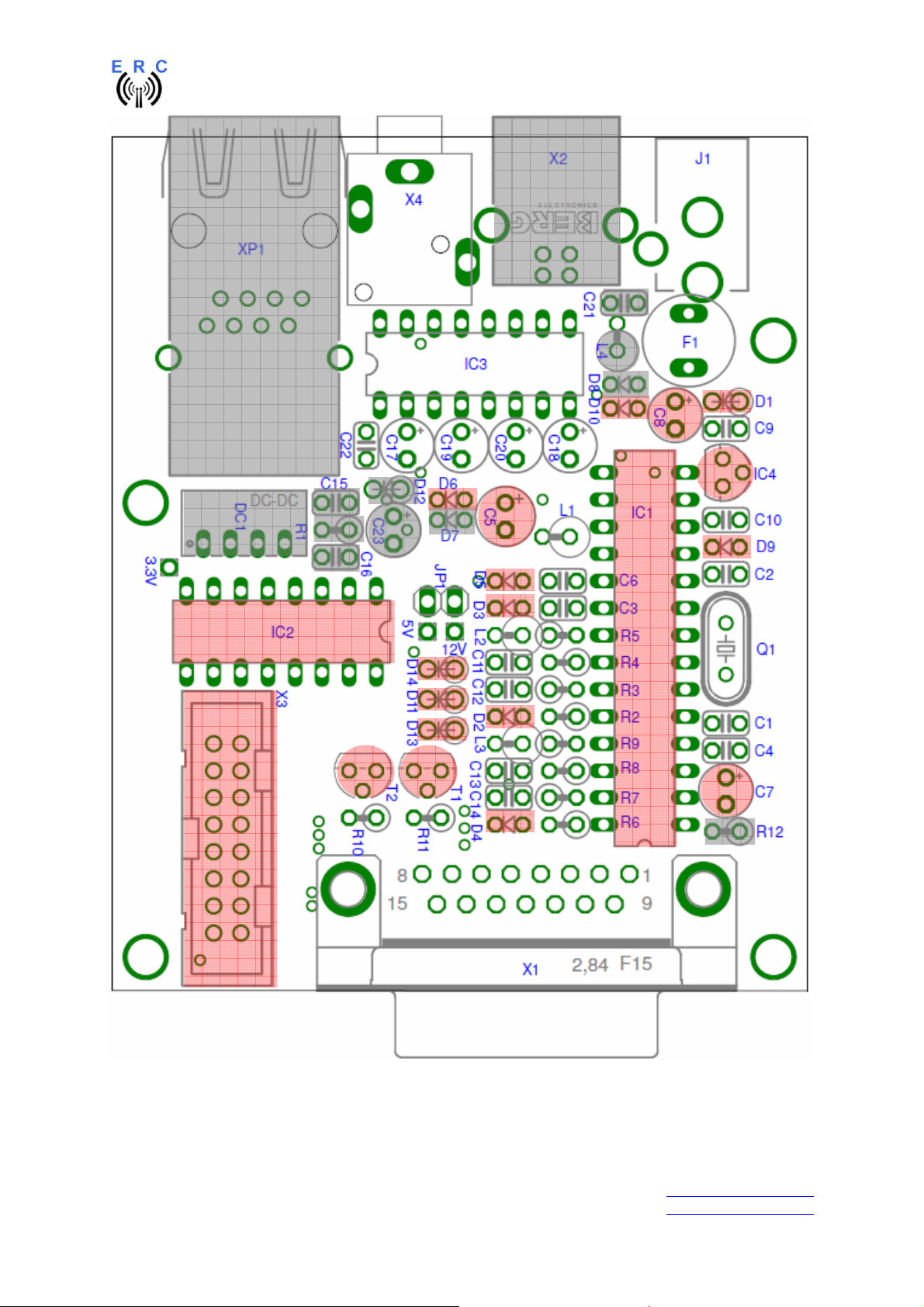
1.3 Assembly of the ERC-M USB PCB
Assemble and solder the components according to the following drawings.
Please read the following instructions before you start:
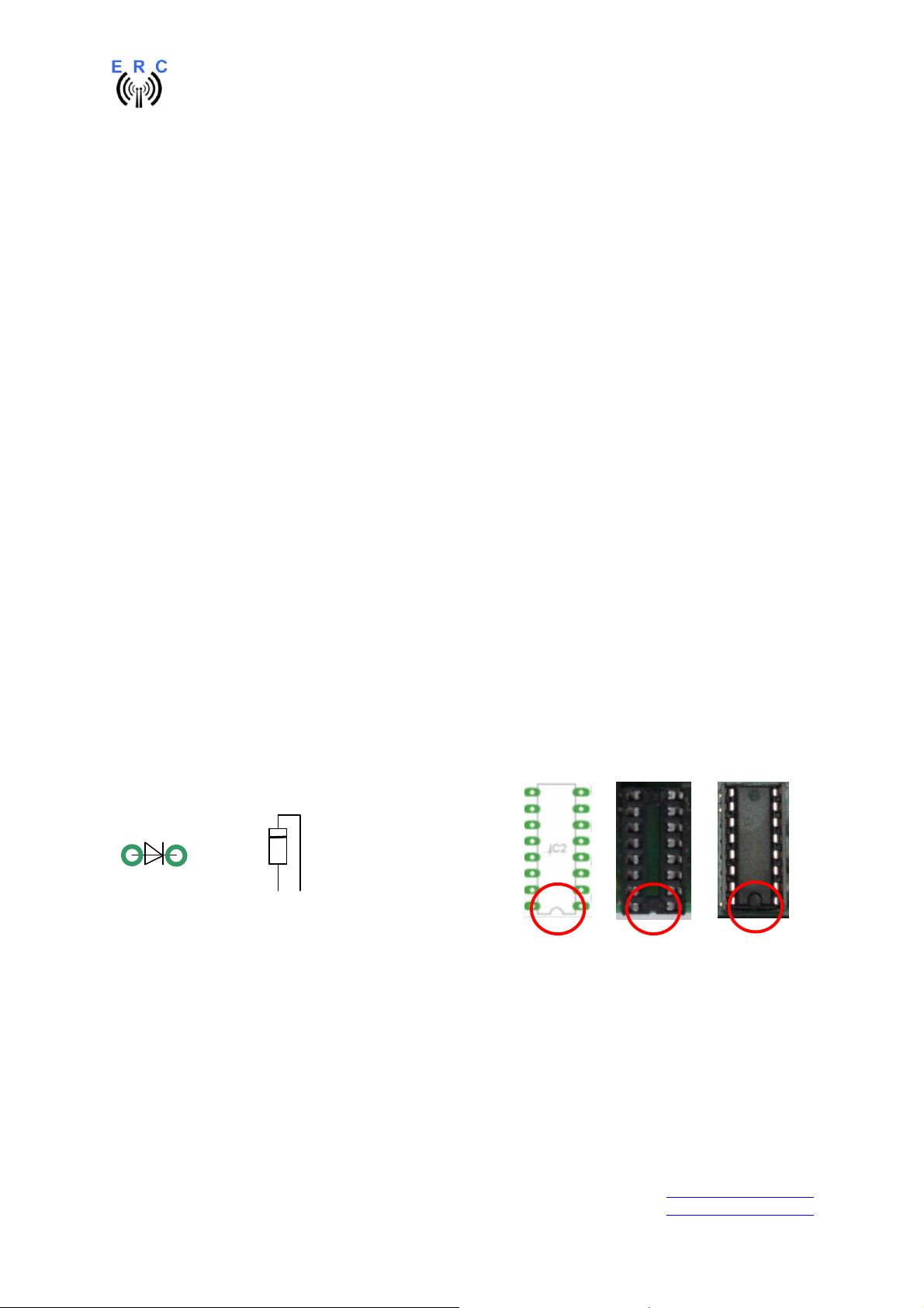
1. The vertical assembled Diodes should have a distance (1-2mm) to the PCB while soldering.
Otherwise there is the risk of overheating these components while soldering.
2. Take care of polarization of the following components (marked red in the assembly drawing):
- Diodes D1,D2,D3,D4,D5,D6,D8,D9,D10,D11,D13,D14
- Capacitor electrolytic C5
- Capacitor tantal C7,C8
- IC-socket for IC1,IC2,IC3
- Transistor T1,T2
- Voltage-regulator IC4
- Box-header X3
3. Carefully compare the position of the PCB with the drawings before you start to assemble it.
Components:
Colour-code of Resistors:
4K7 5% yellow-violet-red-gold
alt.: 4K7 1% yellow-violet-black-brown-brown
20K 5% red-black-orange-gold
alt.: 20K 1% red - black-black-red- brown
39K 5% orange-white-orange-gold
alt.: 33K 1% orange-white- black-red-brown
220K 5% rot-rot-yellow-gold
alt.: 220K 1% rot-rot- black-orange-brown
Colour-code of Coils:
10uH 10% brown-black-black-silver
Diodes : ICs and sockets
=
___________________________________________________________________________
© Ing.-Büro E. Alba de Schmidt web : www.schmidt-alba.de
Tannenstr. 16 Page 4 of 44 email : erc@schmidt-alba.de
86836 Untermeitingen / Germany
This document is for the user only. Any publishing (printed or in electronic form) is not allowed.
Page 5
EASY-ROTOR-CONTROL M V2.2 Instructions
Not to be assembled components are marked grey in the assembly drawing.
___________________________________________________________________________
© Ing.-Büro E. Alba de Schmidt web : www.schmidt-alba.de
Tannenstr. 16 Page 5 of 44 email : erc@schmidt-alba.de
86836 Untermeitingen / Germany
This document is for the user only. Any publishing (printed or in electronic form) is not allowed.
Page 6
EASY-ROTOR-CONTROL M V2.2 Instructions
USB-Module
___________________________________________________________________________
© Ing.-Büro E. Alba de Schmidt web : www.schmidt-alba.de
Tannenstr. 16 Page 6 of 44 email : erc@schmidt-alba.de
86836 Untermeitingen / Germany
This document is for the user only. Any publishing (printed or in electronic form) is not allowed.
Page 7
EASY-ROTOR-CONTROL M V2.2 Instructions
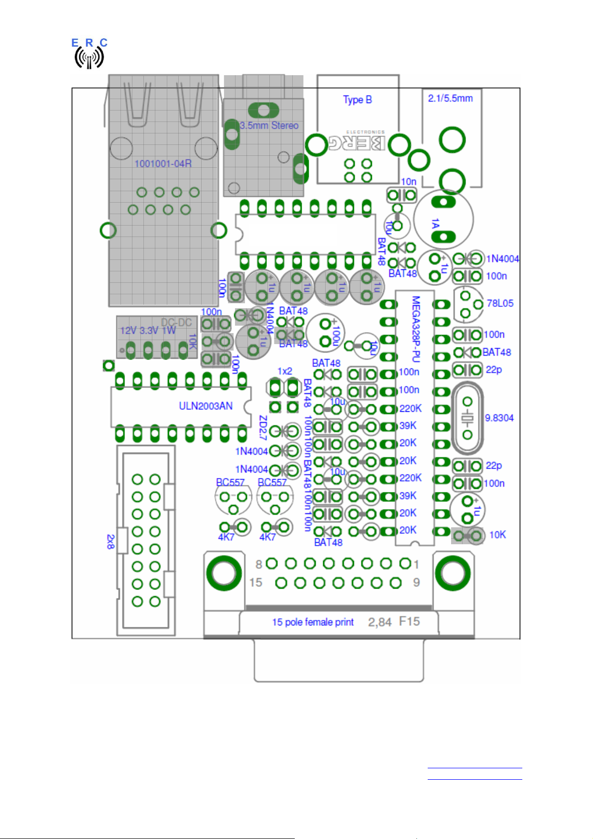
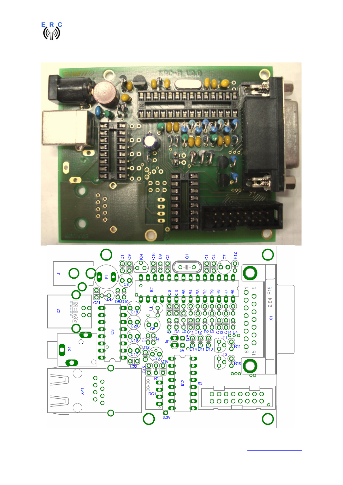
Check carefully the assembly. So, this is how it should look like.
___________________________________________________________________________
© Ing.-Büro E. Alba de Schmidt web : www.schmidt-alba.de
Tannenstr. 16 Page 7 of 44 email : erc@schmidt-alba.de
86836 Untermeitingen / Germany
This document is for the user only. Any publishing (printed or in electronic form) is not allowed.
Page 8
EASY-ROTOR-CONTROL M V2.2 Instructions
So fare, don’t put the ICs (MEGA328, USB-Module and ULN2003) into their sockets.
First a little electrical test should be performed:
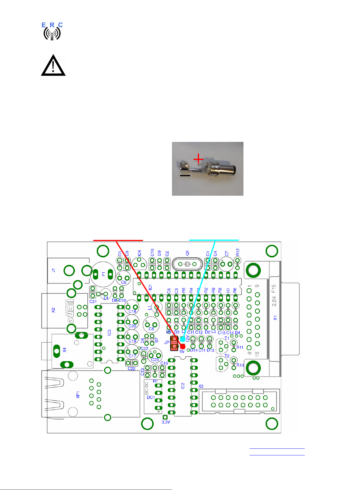
1.4 Connection of the DC-supply and check of the voltage-regulator
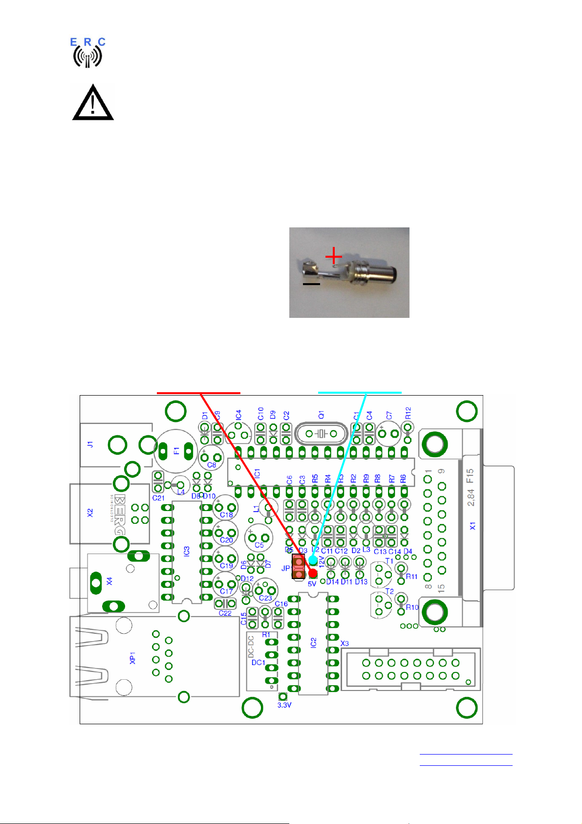
Now put the jumper on the 1x2 pinheader JP1 (the jumper supplies the ERC with +5V).
After checking all assembled components for identity, polarization and solder-bridges, prepare a DCcable with 10 to 15VDC by using the DC-connector supplied with the kit or use any other DC-supply
with that voltage and an appropriate DC-Connector of 2.1/5.5mm.
Connect the Plus(+)-pole to the center contact
and the Minus(-)-pole to the outer contact.
Before connecting the DC-connector to the
ERC-M, measure the voltage at the connector,
if it is in the range needed.
If DC is reversed, nothing will happen as the
Circuit is proven against wrong polarization.
Now plug the DC-connector into J1 of the ERC-M. After connecting DC correctly, you should
measure +5VDC +/-0.2V at the test-point +5V and +10 to +15VDC at test-point +12V against GND.
Disconnect the supply now.
Testpoint +5V Testpoint +12V
GND
___________________________________________________________________________
© Ing.-Büro E. Alba de Schmidt web : www.schmidt-alba.de
Tannenstr. 16 Page 8 of 44 email : erc@schmidt-alba.de
86836 Untermeitingen / Germany
This document is for the user only. Any publishing (printed or in electronic form) is not allowed.
Page 9
EASY-ROTOR-CONTROL M V2.2 Instructions
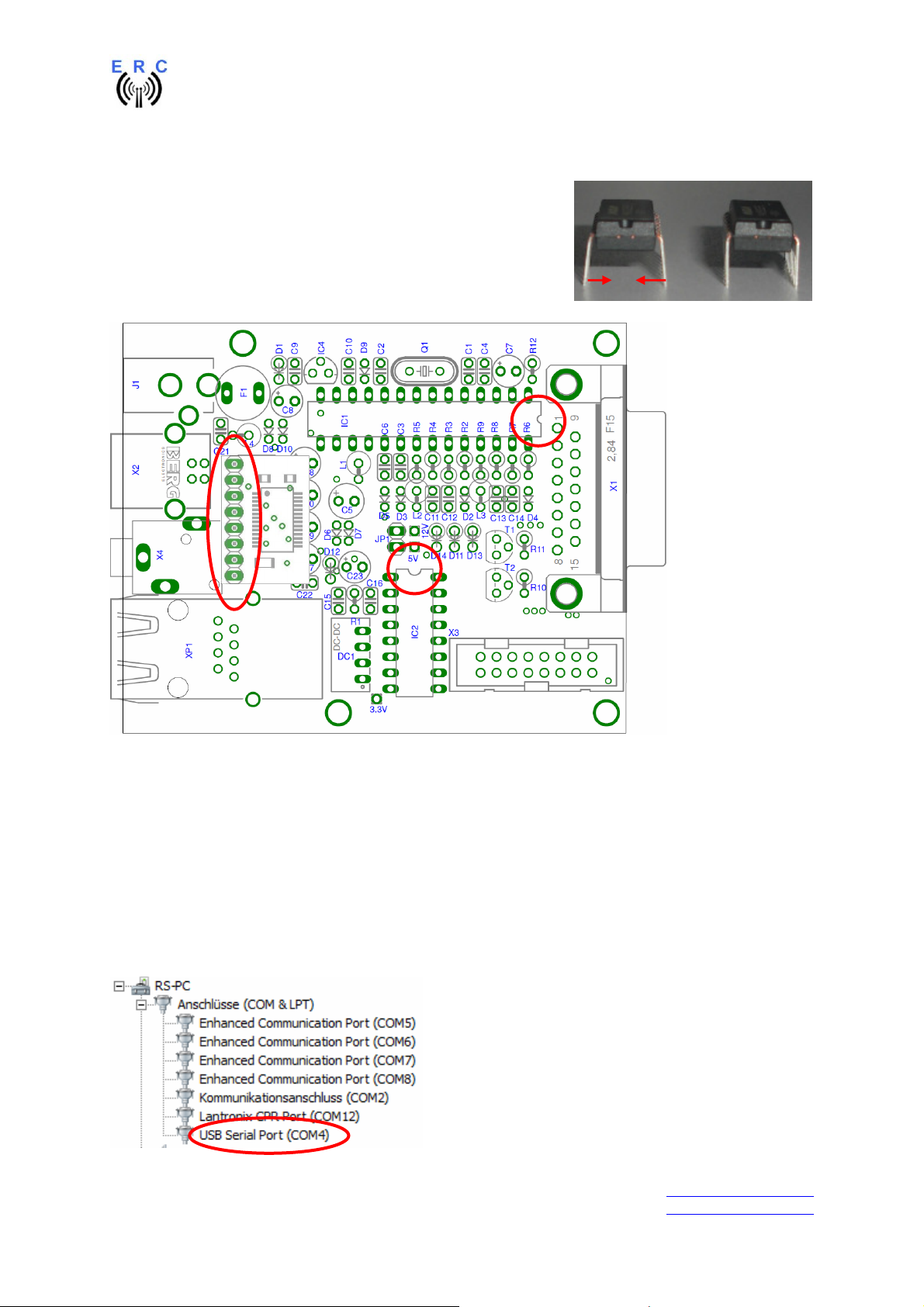
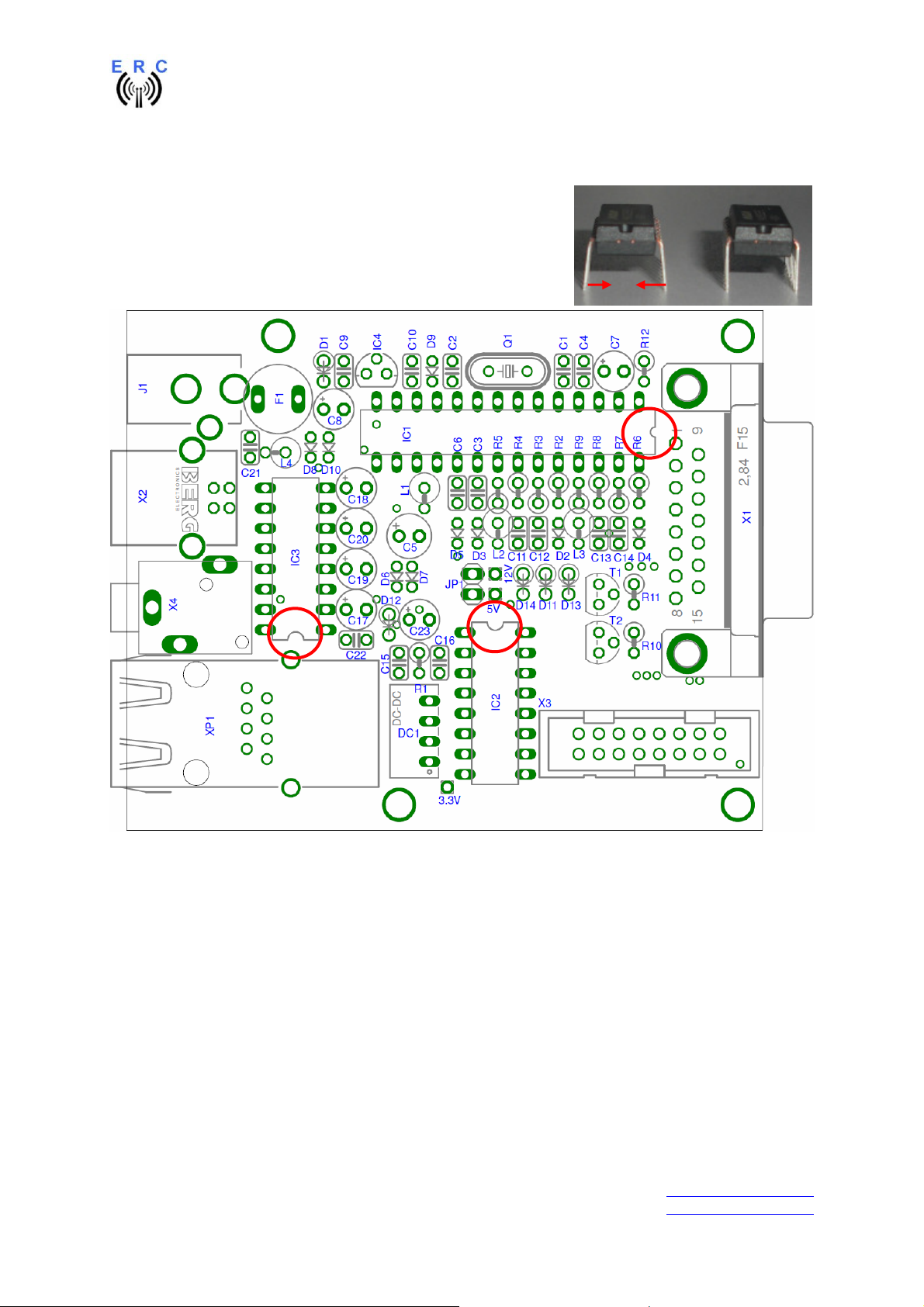
1.5 Insert ICs and the USB-module
The pins of the ICs have to be bend before you can put them into
their sockets. Use a hard base (e.g. your working desk) and
bend the row of pins slightly, that they get an angle of 90°.
Now insert the ICs and take care about direction of the components
and not to bend any pins while inserting the components into the
sockets.
Also insert the USB-module on the socket of IC3 as shown.
1.6 Establishing the USB-connection
Plug the USB-B-connector to the ERC-M and the USB-A-connector to a free USB-connector on your
PC.
Depending on your operating-system, you will be asked to install an USB-driver. This driver is
available on the CD delivered with your kit.
After successful installation of the driver, a new COM-Port (COMn) is available. You can identify the
COM-port-number by inspecting the hardware-settings of your PC. In case you have a conflict with
another COM-port (e.g. virtual COM-port), change the COM-port-number in the properties.
___________________________________________________________________________
© Ing.-Büro E. Alba de Schmidt web : www.schmidt-alba.de
Tannenstr. 16 Page 9 of 44 email : erc@schmidt-alba.de
86836 Untermeitingen / Germany
This document is for the user only. Any publishing (printed or in electronic form) is not allowed.
Page 10

EASY-ROTOR-CONTROL M V2.2 Instructions
2. ERC-M RS232
If your kit is USB (not RS232) go to chapter 1.
2.1 Bill of material (BOM)
The BOM is in the order how you should use the parts.
ERC-M RS232 V2.2 Bill Of Material
QTY Type Value Reference Comments
1 DSUB-connector 9 pole female solder for RS232-cable
1 DSUB-case for 9 pole for RS232-cable
1 Cable with Phone-Jack 3.5mm Stereo 1.25m for RS232-cable
1 PCB ERC-M 2-layer 80x65mm V2.2
C3,C4,C6,C9,C10,C11,
10 Capacitor ceramic 100n 50V 20%
1 Crystal 9.8304 MHz HC49U Q1
2 IC-socket 16 pole DIL16 for IC2, IC3
1 IC-socket 28 pole DIL28 for IC1
2 Capacitor ceramic 22p 16V 5% C1,C2
6 Capacitor tantal 1u 35V 20% C7,C8,C17,C18,C19,C20
1 Phone-Jack 3.5mm Stereo X10
1 Mini-fuse 1.0A F1
2 Transistor BC557 T1,T2 alt. BC558,BC559
1 Voltage-regulator 78L05 TO92 IC4
2 Resistor 4K7 5% R10,R11 alt. 4K7 1%
4 Resistor 20K 5% R2,R3,R6,R7 alt. 20K 1%
2 Resistor 39K 5% R4,R8 alt. 39K 1%
2 Resistor 220K 5% R5,R9 alt. 220K 1%
3 Coil 10u 10% SMCC L1,L2,L3
7 Diode BAT48 D2,D3,D4,D5,D6,D9,D10
3 Diode 1N4004 D1,D11,D13 alt. 1N4007
1 Diode ZD2.7 D14
1 Box-header 2x8 pole X3
1 Pinheader 1x2 pole JP1
1 DC-Jack 2.1/5.5mm J1
1 Capacitor electrolytic 100u 16V 20% C5
1 DSUB-connector 15 pole female print X1
1 DC-Connector 2.1/5.5/9mm for DC-cable
1 DSUB-connector 15 pole male solder for rotor-Cable
1 DSUB-case for 15 pole for rotor-Cable
1 IC MAX232 IC3
1 IC MEGA328P-20PU IC1
1 IC ULN2003AN IC2
1 Jumper blue for JP1 Power/Reset
C12,C13,C14,C22
___________________________________________________________________________
© Ing.-Büro E. Alba de Schmidt web : www.schmidt-alba.de
Tannenstr. 16 Page 10 of 44 email : erc@schmidt-alba.de
86836 Untermeitingen / Germany
This document is for the user only. Any publishing (printed or in electronic form) is not allowed.
Page 11
EASY-ROTOR-CONTROL M V2.2 Instructions
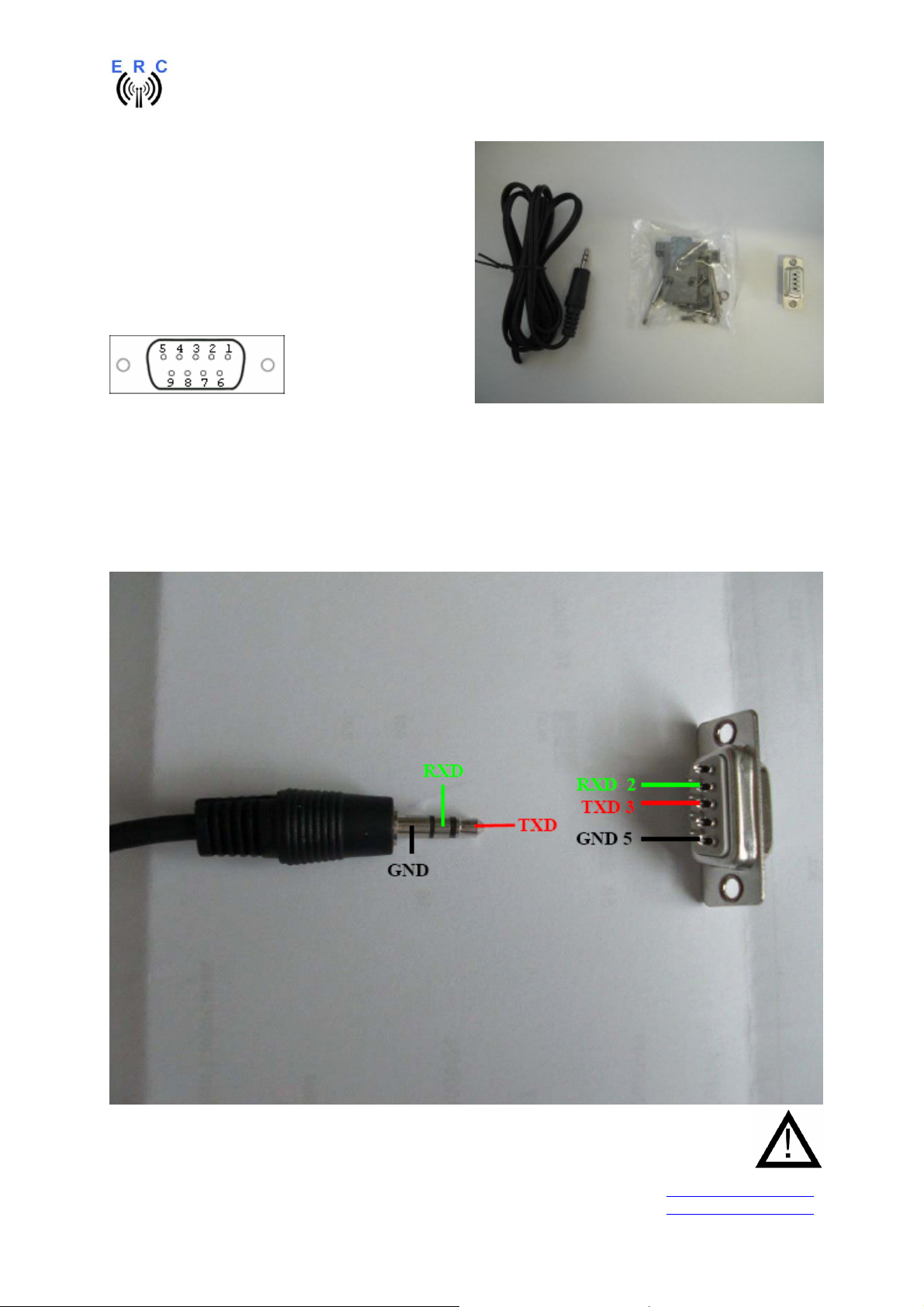
2.2 Assembly of RS232 cable
Materials needed:
- Cable with 3.5mm Stereo phone-jack
- DSUB-connector 9 pole female
- DSUB-case for 9 pole
Pinning of DSUB seen from the connector-frontside
As the delivered cables differ with their colours, it has to be measured which of the inner cables is
connected to what contact of the phone-jack. Alternatively to the 3-wire cable a 2-wire cable with
shielding can be delivered. For this kind of cables the both shielding have to be twisted together. The
shielding is representing GND.
GND: inner contact of the phone-jack : to PIN 5 of the D-SUB
RXD: middle contact of the phone-jack : to PIN 2 of the DSUB
TXD: tip-contact of the phone-jack : to PIN 3 of the DSUB
NOTE: If you use the ERC-M in MASTER-SLAVE-mode over RS232, the pins for RXD and
TXD must be crossed for the Master-ERC-M: TXD to Pin 2 and RXD to Pin3 of the D-SUB.
___________________________________________________________________________
© Ing.-Büro E. Alba de Schmidt web : www.schmidt-alba.de
Tannenstr. 16 Page 11 of 44 email : erc@schmidt-alba.de
86836 Untermeitingen / Germany
This document is for the user only. Any publishing (printed or in electronic form) is not allowed.
Page 12
EASY-ROTOR-CONTROL M V2.2 Instructions
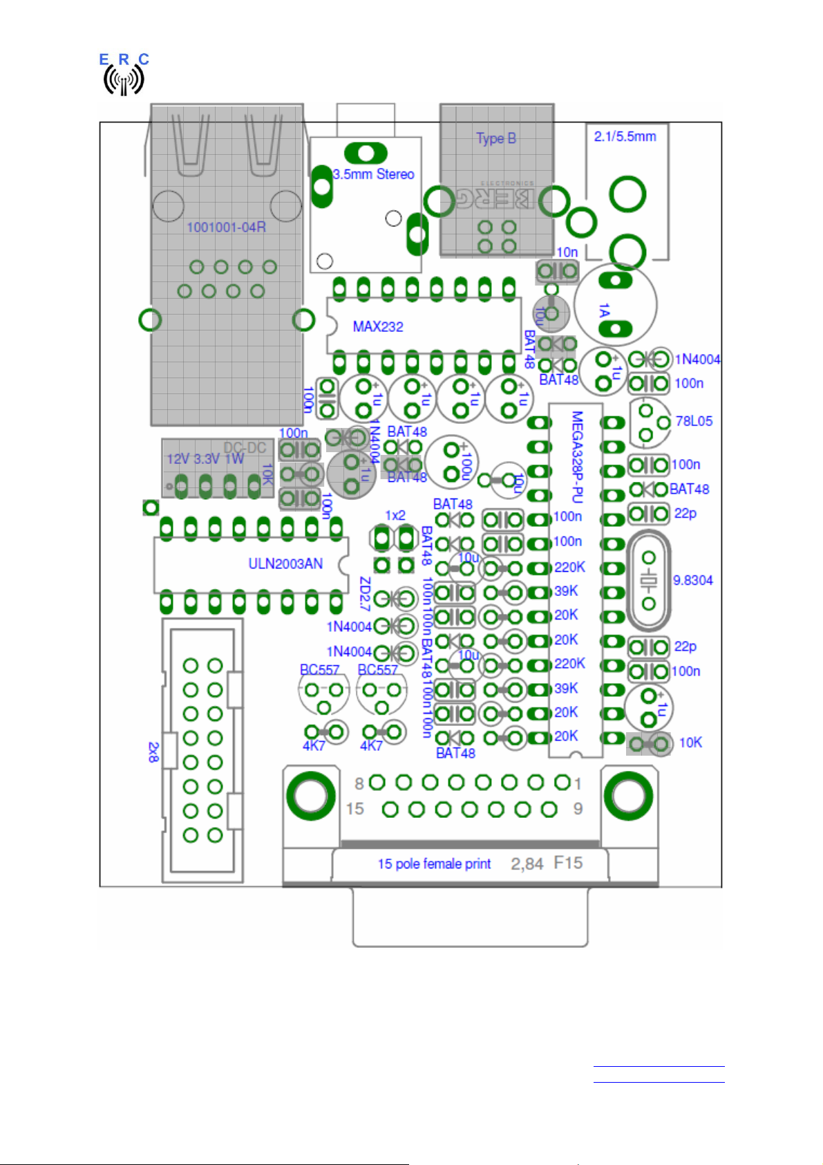
2.3 Assembly of the ERC-M RS232 PCB
Assemble and solder the components according to the following drawings.
Please read the following instructions before you start:
1. The vertical assembled Diodes should have a distance (1-2mm) to the PCB while soldering.
Otherwise there is the risk of overheating these components while soldering.
2. Take care of polarization of the following components (marked red in the assembly drawing):
- Diodes D1,D2,D3,D4,D5,D6,D9,D10,D11,D13,D14
- Capacitor Al C5
- Capacitor tantal C7,C8,C17,C18,C19,C20
- IC-socket for IC1,IC2,IC3
- Transistor T1,T2
- Voltage-regulator IC4
- Box-header X3
3. Carefully compare the position of the PCB with the drawings before you start to assemble it.
Components :
Colour-code of Resistors:
4K7 5% yellow-violet-red-gold
alt.: 4K7 1% yellow-violet-black-brown-brown
20K 5% red-black-orange-gold
alt.: 20K 1% red - black-black-red- brown
39K 5% orange-white-orange-gold
alt.: 33K 1% orange-white- black-red-brown
220K 5% rot-rot-yellow-gold
alt.: 220K 1% rot-rot- black-orange-brown
Colour-code of Coils:
10uH 10% brown-black-black-silver
Diodes : ICs and sockets
=
Not to be assembled components are marked grey in the assembly drawing. These components are
for different interface options.
___________________________________________________________________________
© Ing.-Büro E. Alba de Schmidt web : www.schmidt-alba.de
Tannenstr. 16 Page 12 of 44 email : erc@schmidt-alba.de
86836 Untermeitingen / Germany
This document is for the user only. Any publishing (printed or in electronic form) is not allowed.
Page 13
EASY-ROTOR-CONTROL M V2.2 Instructions
___________________________________________________________________________
© Ing.-Büro E. Alba de Schmidt web : www.schmidt-alba.de
Tannenstr. 16 Page 13 of 44 email : erc@schmidt-alba.de
86836 Untermeitingen / Germany
This document is for the user only. Any publishing (printed or in electronic form) is not allowed.
Page 14
EASY-ROTOR-CONTROL M V2.2 Instructions
___________________________________________________________________________
© Ing.-Büro E. Alba de Schmidt web : www.schmidt-alba.de
Tannenstr. 16 Page 14 of 44 email : erc@schmidt-alba.de
86836 Untermeitingen / Germany
This document is for the user only. Any publishing (printed or in electronic form) is not allowed.
Page 15

EASY-ROTOR-CONTROL M V2.2 Instructions
Check carefully the assembly. So, this is how it should look like.
___________________________________________________________________________
© Ing.-Büro E. Alba de Schmidt web : www.schmidt-alba.de
Tannenstr. 16 Page 15 of 44 email : erc@schmidt-alba.de
86836 Untermeitingen / Germany
This document is for the user only. Any publishing (printed or in electronic form) is not allowed.
Page 16
EASY-ROTOR-CONTROL M V2.2 Instructions
So fare, don’t put the ICs (MEGA328, MAX232 and ULN2003) into their sockets. First
a little electrical test should be performed:
2.4 Connection of the DC-supply and check of the voltage-regulator
Now put the jumper on the 1x2 pinheader JP1 (the jumper supplies the ERC with +5V).
After checking all assembled components for identity, polarization and solder-bridges, prepare a DCcable with 10 to 15VDC by using the DC-connector supplied with the kit or use any other DC-supply
with that voltage and an appropriate DC-Connector of 2.1/5.5mm.
Connect the Plus(+)-pole to the centre contact
and the Minus(-)-pole to the outer contact.
Before connecting the DC-connector to the
ERC-M, measure the voltage at the connector,
if it is in the range needed.
If DC is reversed, nothing will happen as the
Circuit is proven against wrong polarization.
Now plug the DC-connector into J1 of the ERC-M. After connecting DC correctly, you should
measure +5VDC +/-0.2V at the test-point +5V and +10 to +15VDC at test-point +12V against GND.
Disconnect the supply now.
Testpoint +5V Testpoint +12V
GND
___________________________________________________________________________
© Ing.-Büro E. Alba de Schmidt web : www.schmidt-alba.de
Tannenstr. 16 Page 16 of 44 email : erc@schmidt-alba.de
86836 Untermeitingen / Germany
This document is for the user only. Any publishing (printed or in electronic form) is not allowed.
Page 17
EASY-ROTOR-CONTROL M V2.2 Instructions
2.5 Insert ICs
The pins of the ICs have to bend before you can put them into
their sockets. Use a hard base (e.g. your working desk) and
bend the row of pins slightly, that they get an angle of 90°.
Now insert the ICs and take care about direction of the components
and not to bend any pins while inserting the components into the
sockets.
___________________________________________________________________________
© Ing.-Büro E. Alba de Schmidt web : www.schmidt-alba.de
Tannenstr. 16 Page 17 of 44 email : erc@schmidt-alba.de
86836 Untermeitingen / Germany
This document is for the user only. Any publishing (printed or in electronic form) is not allowed.
Page 18

EASY-ROTOR-CONTROL M V2.2 Instructions
3. LAN-Interface (optional)
3.1 Bill of material
The BOM is in the order how you should use the parts.
ERC-M V2.0 LAN Bill Of Material
QTY Type Value Reference Comments
1 Diode 1N4004 D12 alt. 1N4007
2 Capacitor ceramic 100n 50V 20% C15,C16
1 Capacitor Tantal 1u 35V 20% C23
2 Resistor 10K 5% R1,R12 alt. 10K 1%
1 Diode BAT48 D7
1 XPORT 1001001-04R XP1 alt. 1001000-04R
1 DC/DC 12V 3.3V 1W DC1
1 Patchcable 2m Crossover
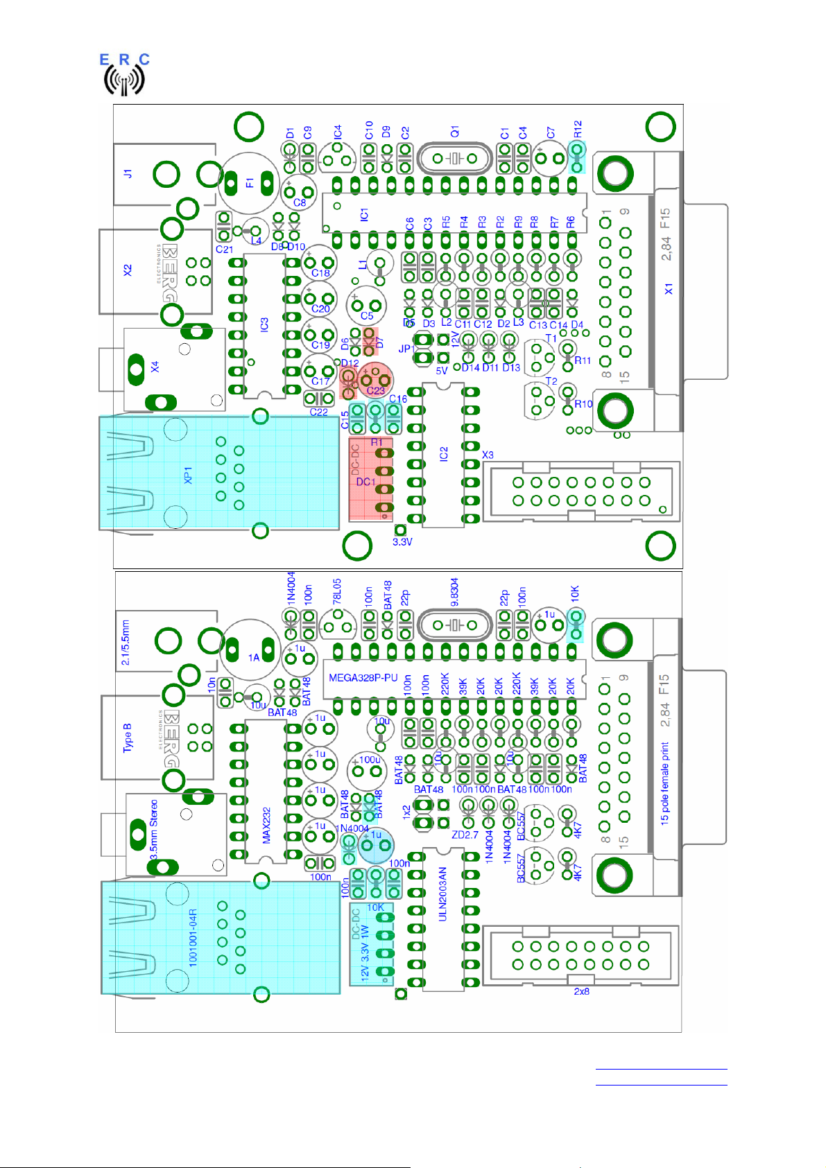
3.2 Assembly of the LAN-Interface
Assemble and solder the components according to the following drawings. The components to be
assembled are marked blue in the following drawings.
Please read the following instructions before you start:
1. The vertical assembled Diodes should have a distance (1-2mm) to the PCB while soldering.
Otherwise there is the risk of overheating these components while soldering.
2. Take care of polarization of the following components :
- Diode D7,D12
- DC/DC DC1
- Capacitor tantal C23
Those components are marked red in the following drawing.
It is important to solder the ground-lugs of the XPORT properly as they are used for heat-dissipation
from the XPORT to the printed board.
Components :
Colour-code of Resistors:
10K 5% brown-black-orange-gold
alt.: 10K 1% brown-black-black-red-brown
Diodes :
=
___________________________________________________________________________
© Ing.-Büro E. Alba de Schmidt web : www.schmidt-alba.de
Tannenstr. 16 Page 18 of 44 email : erc@schmidt-alba.de
86836 Untermeitingen / Germany
This document is for the user only. Any publishing (printed or in electronic form) is not allowed.
Page 19
EASY-ROTOR-CONTROL M V2.2 Instructions
___________________________________________________________________________
© Ing.-Büro E. Alba de Schmidt web : www.schmidt-alba.de
Tannenstr. 16 Page 19 of 44 email : erc@schmidt-alba.de
86836 Untermeitingen / Germany
This document is for the user only. Any publishing (printed or in electronic form) is not allowed.
Page 20
EASY-ROTOR-CONTROL M V2.2 Instructions
This is how it should look like:
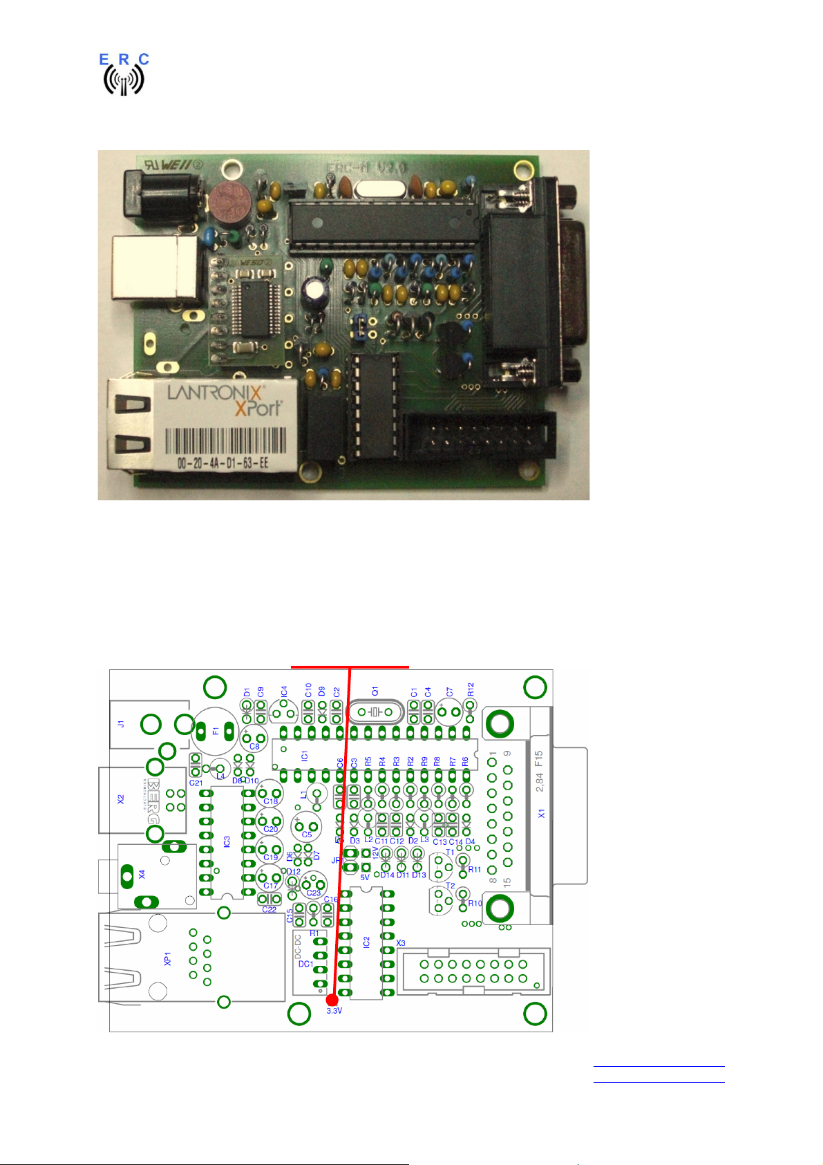
3.4 Check of the DC/DC-converter
After checking all assembled components for identity, polarization and solder-bridges, connect 10 to
15VDC to connector J1 as already performed in chapter 1.3.
After connecting DC correctly, you should measure +3.3VDC +/-0.4V at the testpoint shown against
GND.
Testpoint : +3.3V
GND
___________________________________________________________________________
© Ing.-Büro E. Alba de Schmidt web : www.schmidt-alba.de
Tannenstr. 16 Page 20 of 44 email : erc@schmidt-alba.de
86836 Untermeitingen / Germany
This document is for the user only. Any publishing (printed or in electronic form) is not allowed.
Page 21

EASY-ROTOR-CONTROL M V2.2 Instructions
3.5 Device-Installer
The Device-Installer is needed to assign an IP-address to the LAN-Unit:
The Device-Installer is available on the disk supplied with your ERC-M in the LANTRONIX-folder.
You may find a newer version on the LANTRONIX homepage at www.lantronix.com.
First connect the ERC-M with the cross-over patch-cable to your PC.
Start the setup with the file: setup_di_x86x64cd_4.3.0.2.exe
The unit’s IP address is normally set to 0.0.0.0 at the factory. The hardware address is on the product
label. The unit is DHCP enabled as the default.
- Click Start – Programs – Lantronix – DeviceInstaller - DeviceInstaller. If your PC has more
than one network adapter, a message displays. Select an adapter and click OK. Note: If the
unit already has an IP address (e.g., DHCP has assigned an IP-address), click the Search
icon and select the unit from the list of Lantronix device servers on the local network.
- Click the Assign IP icon .
- If prompted, enter the hardware address (on the product label) in the format 00-20-4a-XX-XX-
XX, where the XXs are unique numbers/letters assigned to the product. Click Next.
- Select Assign a specific IP address and click Next.
- Enter the IP address. The Subnet mask displays automatically based on the IP-address; if
desired, you may change it. On a local network, you can leave the Default gateway blank (all
zeros). Click Next.
- Click the Assign button and wait several seconds until a confirmation message displays. Click
Finish.
- Select the XPort from the main window list and click Tools - Ping. The results display in the
Status area. Click the Clear Status button to clear the window so you can ping the device
again.
- Click the Close button.
In case of any problems, disable the Windows-Firewall during the assignment of the IP-address and
repeat the configuration.
3.6 Installation of the COM-Port-Redirector (CPR)
The CPR is needed to redirect the LAN-device to a virtual-COM-port that can be accessed by the
rotor-control-software.
The following items are required to run CPR:
- x86 (32bit): Windows XP, 2003 Server, Vista, 7, and 2008 Server
- x64 (64bit): Windows Vista, 7, and 2008 Server
- Microsoft .NET Framework v4.0.
- 30MB free hard drive space.
The "Internet Connection Firewall" must be disabled, or else UDP Ports 30718, 43282, 43283 must be
available. Otherwise, you will not be able to detect or communicate with any devices on the
network. To configure, go to the Control Panel, go to Network Settings, select the corresponding
network adapter, choose Properties, and go to the Advanced tab. You may need to allow these ports
access through the corporate firewall as well.
The CPR-software is available on the disk supplied with your ERC-M in the LANTRONIX-folder.
You may find a newer version on the LANTRONIX homepage at www.lantronix.com.
___________________________________________________________________________
© Ing.-Büro E. Alba de Schmidt web : www.schmidt-alba.de
Tannenstr. 16 Page 21 of 44 email : erc@schmidt-alba.de
86836 Untermeitingen / Germany
This document is for the user only. Any publishing (printed or in electronic form) is not allowed.
Page 22

EASY-ROTOR-CONTROL M V2.2 Instructions
Start the setup with the file: setup_cpr_x86x64cd_4.3.0.0.exe
You will find a quick-start-guide for CPR in the LANTRONIX-folder on the CD:
Com-Port-Redirector_QS.PDF
By default, the serial speed of the LAN-device is set to 9600 Baud. If you want to use it with a different
speed, as your application doesn’t support 9600 Baud, change the speed settings with the Webinterface available through the CRP-software.
As the LAN-device only supports 1 configured speed, it cannot be used with the Service-Tool to
- change speed of communication
- perform a firmware-update
These actions are only available through the primary interface (USB, RS232).
___________________________________________________________________________
© Ing.-Büro E. Alba de Schmidt web : www.schmidt-alba.de
Tannenstr. 16 Page 22 of 44 email : erc@schmidt-alba.de
86836 Untermeitingen / Germany
This document is for the user only. Any publishing (printed or in electronic form) is not allowed.
Page 23
EASY-ROTOR-CONTROL M V2.2 Instructions
4. Rotor-Card (optional)
4.1 Bill of material
The BOM is in the order how you should use the parts.
Rotor-card V1.6 Bill Of Material
QTY Type Value Reference Comments
1 PCB RC 2-layer 67.5x43.6mm V1.6
1 Capacitor ceramic 100n 50V 20% C1
3 Diode 1N4004 D1,D2,D3 alt. 1N4007
1 Diode P6KE33CA D4
1 Coil 10u 10% SMCC L1
1 Terminal-block 2 pol. 5mm X6
5 Terminal-block 3 pol. 5mm X1,X2,X3,X4,X5
1 Connector Mini-DIN 6-pole print X7
3 Relay FTR F1CA012V K1,K2,K3
4 Spring-washer 3.2mm
4 Screw M3x8mm
2 Nut M3
2 Mounting-angle 11x10x7mm
1 Cable with 6-pole mini-DIN 1m To ERC-M
1 Cable black 0.5m 0.75sqmm for cableing
1 Cable blue 0.5m 0.75sqmm for cableing
3 Cable-tie 150mm for cableing
alt. LMR2-12D
alt. RT424012
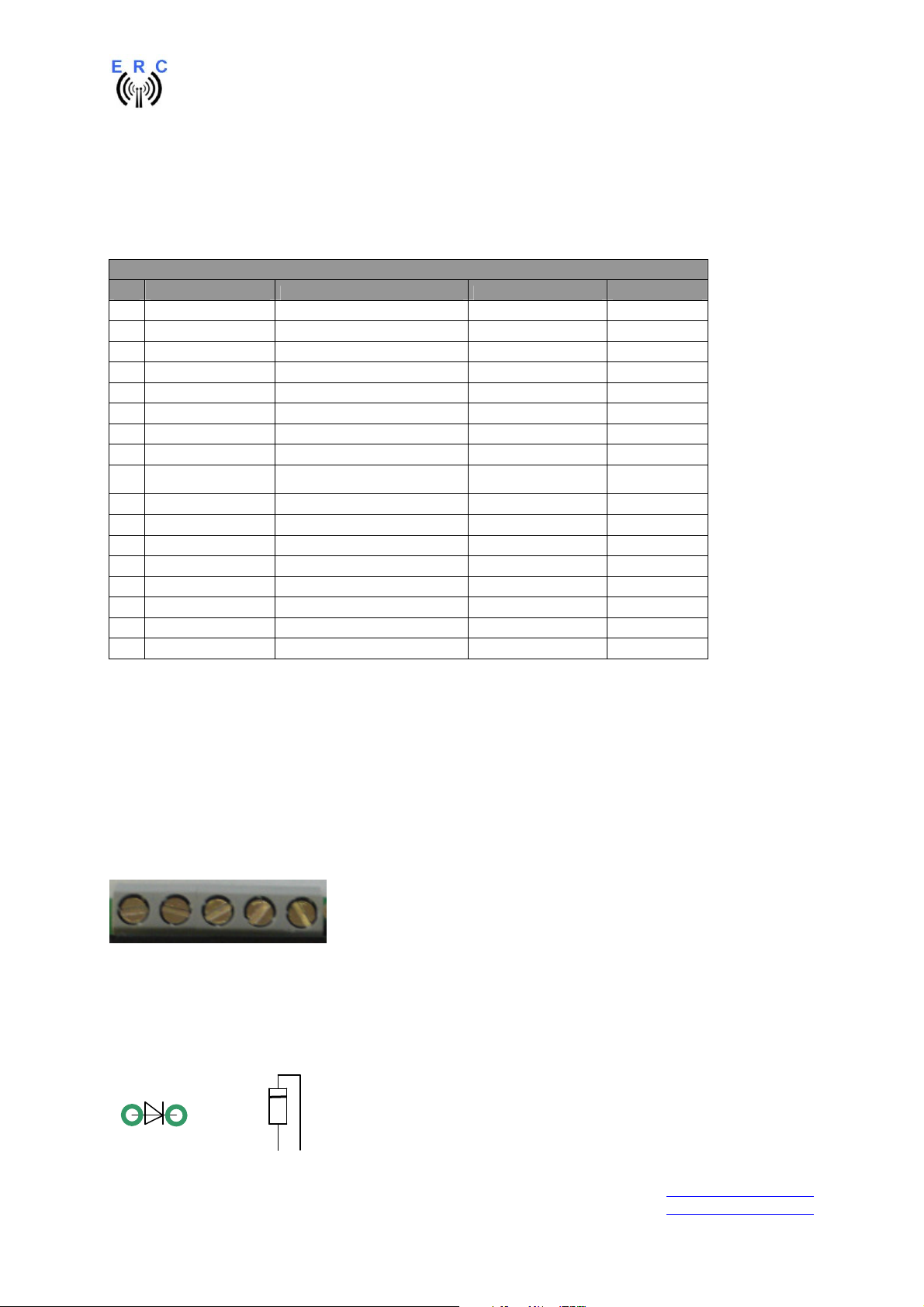
4.2 Assembly of the Rotor-Card PCB
Assemble and solder the components according to the following drawings.
Please read the following instructions before you start:
1. The vertical assembled Diodes should have a distance (1-2mm) to the PCB while soldering.
Otherwise there is the risk of overheating these components while soldering.
2. Put the 2-pole terminal-block X6 and the 3-pole terminal block X2 together before assembly. You
will get a 5-pole terminal-block.
Do the same with 2 of the 3-pole terminal-blocks for X1 and X3 to build a 6-pole terminal-block.
3. Take care of polarization of the following components :
- Diodes D1,D2,D3 (D4 is bidirectional, no polarization)
- Terminal-blocks X1,X2,X3,X4,X5,X6 (cable entry to the outside)
Those components are marked red in the following drawing.
Diodes :
=
___________________________________________________________________________
© Ing.-Büro E. Alba de Schmidt web : www.schmidt-alba.de
Tannenstr. 16 Page 23 of 44 email : erc@schmidt-alba.de
86836 Untermeitingen / Germany
This document is for the user only. Any publishing (printed or in electronic form) is not allowed.
Page 24
EASY-ROTOR-CONTROL M V2.2 Instructions
6
5
5
3
1
2
4
After assembly, attach the 2 mounting-angles with 2 screws and 2 nuts. Use spring-washers below the
nuts.
___________________________________________________________________________
© Ing.-Büro E. Alba de Schmidt web : www.schmidt-alba.de
Tannenstr. 16 Page 24 of 44 email : erc@schmidt-alba.de
86836 Untermeitingen / Germany
This document is for the user only. Any publishing (printed or in electronic form) is not allowed.
Page 25
EASY-ROTOR-CONTROL M V2.2 Instructions
Check carefully the assembly. So, this is how it should look like.
4.3 Connection of the Rotor-Card
The connection between Rotor-Card and ERC-M has to be done with the 6-pin Mini-DIN-cable
supplied with the Rotor-Card-kit. The connections are shown in the next picture. Connect the pins with
the same colour between the Mini-DIN-connector and the D-SUB-connector for axis 1 or axis 2.
1 or 2 rotators can be connected to ERC-M.
- In an AZ/EL-configuration connect AZ to axis 1 and EL to axis 2.
- If you only use 1 rotator, use axis 1.
Connector of ERC-M seen from outside
Connector of Rotor-Card seen from outside
___________________________________________________________________________
© Ing.-Büro E. Alba de Schmidt web : www.schmidt-alba.de
Tannenstr. 16 Page 25 of 44 email : erc@schmidt-alba.de
86836 Untermeitingen / Germany
This document is for the user only. Any publishing (printed or in electronic form) is not allowed.
Page 26

EASY-ROTOR-CONTROL M V2.2 Instructions
Mini-DIN Rotor-Card Signal D-SUB ERC-M
axis 1
1 CW/UP 9 15
2 CCW/DOWN 2 7
3 AUX 11 13
4 Feedback-voltage 1 8
5 GND 10 14
6 DC-supply 12 12
D-SUB ERC-M
axis 2
4.4 Test of Rotor-Card
The Rotor-Card should be electrically tested before you connect it to the rotator-control-box. Perform
the test as follows:
-
Connect the Rotor-Card to the ERC-M by use of the cable prepared in chapter 4.3
-
Connect 12V DC to the DC-connector of the ERC-M. The Rotor-Cards cannot work without
the external DC-supply.
- Measure the voltage between the test-points TP_GND und TP_+12V. You should measure
now the 12V. Also the polarity is very important. You should measure +12V at TP_+12V
against TP-GND. If the polarity is wrong, the Mini-DIN-cable is wired wrong.
V
- Now connect the ERC-M to the PC and start the Service-Tool.
- Press the Test-button of the Service-Tool.
- The relays of the Rotor-Card(s) will now engage in the following sequence in steps of 1
second: CW 1 / CCW 1 / CW 2 / CCW 2 / AUX 1 / AUX 2
4.5 Installation of the Rotor-Card into a control-box
Rotor-cards are to be mounted inside the control-boxes that don’t provide a remote connector.
Therefore you need to drill 3 holes in the housing of the control-box according to this drawing:
___________________________________________________________________________
© Ing.-Büro E. Alba de Schmidt web : www.schmidt-alba.de
Tannenstr. 16 Page 26 of 44 email : erc@schmidt-alba.de
86836 Untermeitingen / Germany
This document is for the user only. Any publishing (printed or in electronic form) is not allowed.
Page 27

EASY-ROTOR-CONTROL M V2.2 Instructions
all values in mm (milli-meter)
First drill the centre-hole (10mm) and than the smaller holes.
Take care, that the bottom-side of the rotor-card has at least a distance of 8mm to
the housing. This is very important to keep the safety-distances, especially when the rotorcard is carrying main-voltage (e.g. the brake-circuit of a HAM-IV).
Mount the rotor-card to the control-box using the 2 screws and spring-washers below the screws.
The wiring of the rotor-card to the different control-boxes is shown in the Installation-Guide provided
on the CD of your ERC-M-kit.
___________________________________________________________________________
© Ing.-Büro E. Alba de Schmidt web : www.schmidt-alba.de
Tannenstr. 16 Page 27 of 44 email : erc@schmidt-alba.de
86836 Untermeitingen / Germany
This document is for the user only. Any publishing (printed or in electronic form) is not allowed.
Page 28

EASY-ROTOR-CONTROL M V2.2 Instructions
5. SlimLine housing (optional)
Mount the front-panel to the aluminium-casting
Put the 4 rubber-feet to the bottom-side of the
housing
Remove the 2 distance-bolts from the DSUBconnector on the ERC-M
Slide the ERC-M into the housing and mount the
back-panel to the housing. READY
Mount the back-panel to the ERC-M using the 2
bolts
Pull the label from its foil and put it carefully on
the top of the housing. Pay attention not to touch
the sticky side of the label.
___________________________________________________________________________
© Ing.-Büro E. Alba de Schmidt web : www.schmidt-alba.de
Tannenstr. 16 Page 28 of 44 email : erc@schmidt-alba.de
86836 Untermeitingen / Germany
This document is for the user only. Any publishing (printed or in electronic form) is not allowed.
Page 29

EASY-ROTOR-CONTROL M V2.2 Instructions
6. HID AZ/AZ or AZ/EL and desktop housing (optional)
The HID is a human-interface-device and provides a 2x16 character LCD-display, 6 LEDs and 4
pushbuttons to the user. The HID and ERC-M is mounted in a powder-coated and silkscreen printed
black sheet-metal-housing.
The desktop-housing is available with different front-panels. One for AZ/AZ and one for AZ/EL
operation. Beside the different housings, the top-side assembly of the HID-PCB for these 2 versions is
different.
6.1 Bill of material
The BOM is in the order how you should use the parts.
ERC-M V2.0 HID+Desktop-housing Bill Of Material
QTY Type Value Reference Comments
Assembly of bottom-side of PCB
1 PCB HID 2-layer 119.8x36.6mm V1.2
4 Diode 1N4004 D1,D2,D3,D4 Alt. 1N4148
6 Resistor 300R 5% R2,R3,R4,R5,R6,R7 Alt. 300R 1%
1 Resistor 54R 5% R8 Alt. 53.6R 1%
1 Potentiometer 10KA R1
1 Box-header 2x8 pole X2
1 Pinheader 1x2 pole JP1
Assembly of top-side of PCB
1 LCD with backlight DIS1
1 Pinheader 1x16 pole for LCD
4 Spacer 2.5x5x5mm LCD-mounting
4 Spring-washer 2.6mm LCD-mounting
4 Screw M2.5x12mm LCD-mounting
4 Nut M2.5 LCD-mounting
4 Switch 3FTL6 S5,S6,S7,S8
4 LED green 3mm LC LED5,LED6,LED7,LED8
2 LED yellow 3mm LC LED9,LED10
6 Spacer 3x12x4mm for LEDs
4 Dome 19mm for switches
Cableing
1 Flat ribbon cable 330mm 16 pol. for cables
2 Connector 2x8 pole for HID to ERC-M cable
1 DSUB-connector 15 pole male flat ribbon for D-SUB-cable
1 DSUB-connector 15 pole female flat ribbon for D-SUB-cable
1 DSUB mounting-kit UNC for D-SUB
Mechanical integration
1 Housing steel AZ/AZ or AZ/EL bottom and cover
4 Rubberfeet d=12mm for housing
8 Screw M3x6mm PCB-/HID-mounting
8 Screw 2.9mm x 6.5mm black for housing
1 Tool Allen-key 2.5mm for housing/rubberfeet
___________________________________________________________________________
© Ing.-Büro E. Alba de Schmidt web : www.schmidt-alba.de
Tannenstr. 16 Page 29 of 44 email : erc@schmidt-alba.de
86836 Untermeitingen / Germany
This document is for the user only. Any publishing (printed or in electronic form) is not allowed.
Page 30

EASY-ROTOR-CONTROL M V2.2 Instructions
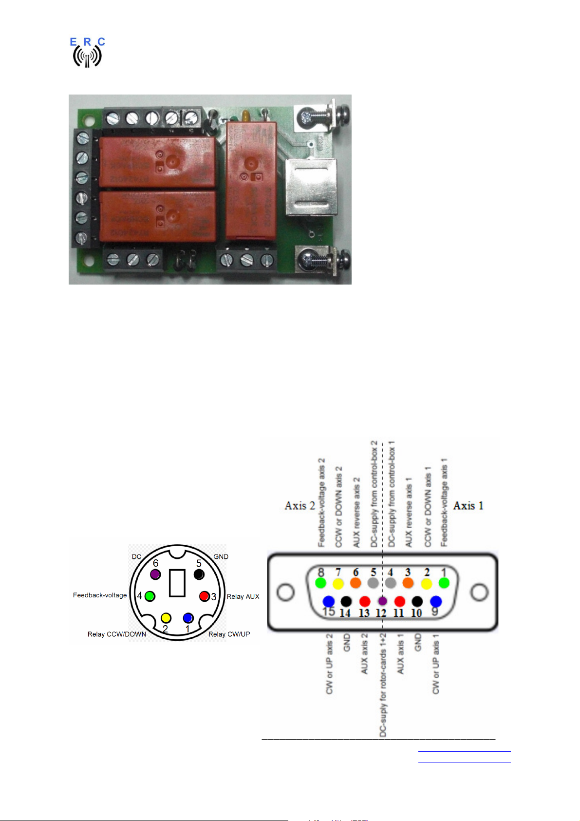
6.2 Assembly of bottom-side HID-PCB
Assemble and solder the components according to the following drawings.
Please read the following instructions before you start:
Take care of polarization of the following components:
- Diodes D1,D2,D3,D4
- Box-header X2
Those components are marked red in the following drawing.
Carefully compare the position of the PCB with the drawings before you start to assemble it.
Components :
Colour-code of Resistors:
54R 5% green-yellow-black-gold
alt.: 53.6R 1% green-orange-blue-gold-brown
300R 5% orange-black-brown-gold
alt.: 300R 1% orange-black-black-black-brown
This is how it should look like:
Inspect carefully the assembly and soldering. Once the LCD is mounted (next step),
it becomes quite difficult to rework any soldering or assembly of the bottom-side !
___________________________________________________________________________
© Ing.-Büro E. Alba de Schmidt web : www.schmidt-alba.de
Tannenstr. 16 Page 30 of 44 email : erc@schmidt-alba.de
86836 Untermeitingen / Germany
This document is for the user only. Any publishing (printed or in electronic form) is not allowed.
Page 31

EASY-ROTOR-CONTROL M V2.2 Instructions
K
6.3 Assembly of top-side HID-PCB AZ/AZ (dual azimuth)
If your housing is AZ/EL (azimuth and elevation) proceed with step 6.4
First assemble the LCD with the 5mm spacers, screws, nuts and spring-washers to the PCB. Put the
16-pole pin-header between PCB and LCD before mounting. Leave the protection-foil on the LCD until
the HID will be mounted into the housing.
Now solder the 16-pole pin-header first to the LCD and than to the PCB.
This is how it should look like:
Please read the following instructions before you proceed:
LEDs:
flat side
short leg
long leg
round side
Take care of polarization of the following components :
- LED5,LED6,LED7,LED8,LED9,LED10
Those components are marked red in the following drawing.
Assemble and solder the switches and LEDs according to the drawings.
Take care that the switches fit plane to the PCB. Otherwise you will have problems with sticky
switches later when the HID is mounted to the front-panel.
___________________________________________________________________________
© Ing.-Büro E. Alba de Schmidt web : www.schmidt-alba.de
Tannenstr. 16 Page 31 of 44 email : erc@schmidt-alba.de
86836 Untermeitingen / Germany
This document is for the user only. Any publishing (printed or in electronic form) is not allowed.
Page 32
EASY-ROTOR-CONTROL M V2.2 Instructions
Hint: Only solder 1 leg of the switches and LEDs, check for alignment and than solder the remaining
pins.
Use the 3x12x4mm spacers for the LEDs to fix them in the right distance from the PCB.
K K
K
K
Put the 19mm domes on top of the switches.
This is how it should look like:
K
K
___________________________________________________________________________
© Ing.-Büro E. Alba de Schmidt web : www.schmidt-alba.de
Tannenstr. 16 Page 32 of 44 email : erc@schmidt-alba.de
86836 Untermeitingen / Germany
This document is for the user only. Any publishing (printed or in electronic form) is not allowed.
Page 33
EASY-ROTOR-CONTROL M V2.2 Instructions
K
6.4 Assembly of top-side HID-PCB AZ/EL (azimuth&elevation)
If your housing is AZ/AZ (dual azimuth) go back to step 6.3
First assemble the LCD with the 5mm spacers, screws, nuts and spring-washers to the PCB. Put the
16-pole pin-header between PCB and LCD before mounting. Leave the protection-foil on the LCD until
the HID will be mounted into the housing.
Now solder the 16-pole pin-header first to the LCD and than to the PCB.
This is how it should look like:
Please read the following instructions before you proceed:
LEDs:
flat side
short leg
long leg
round side
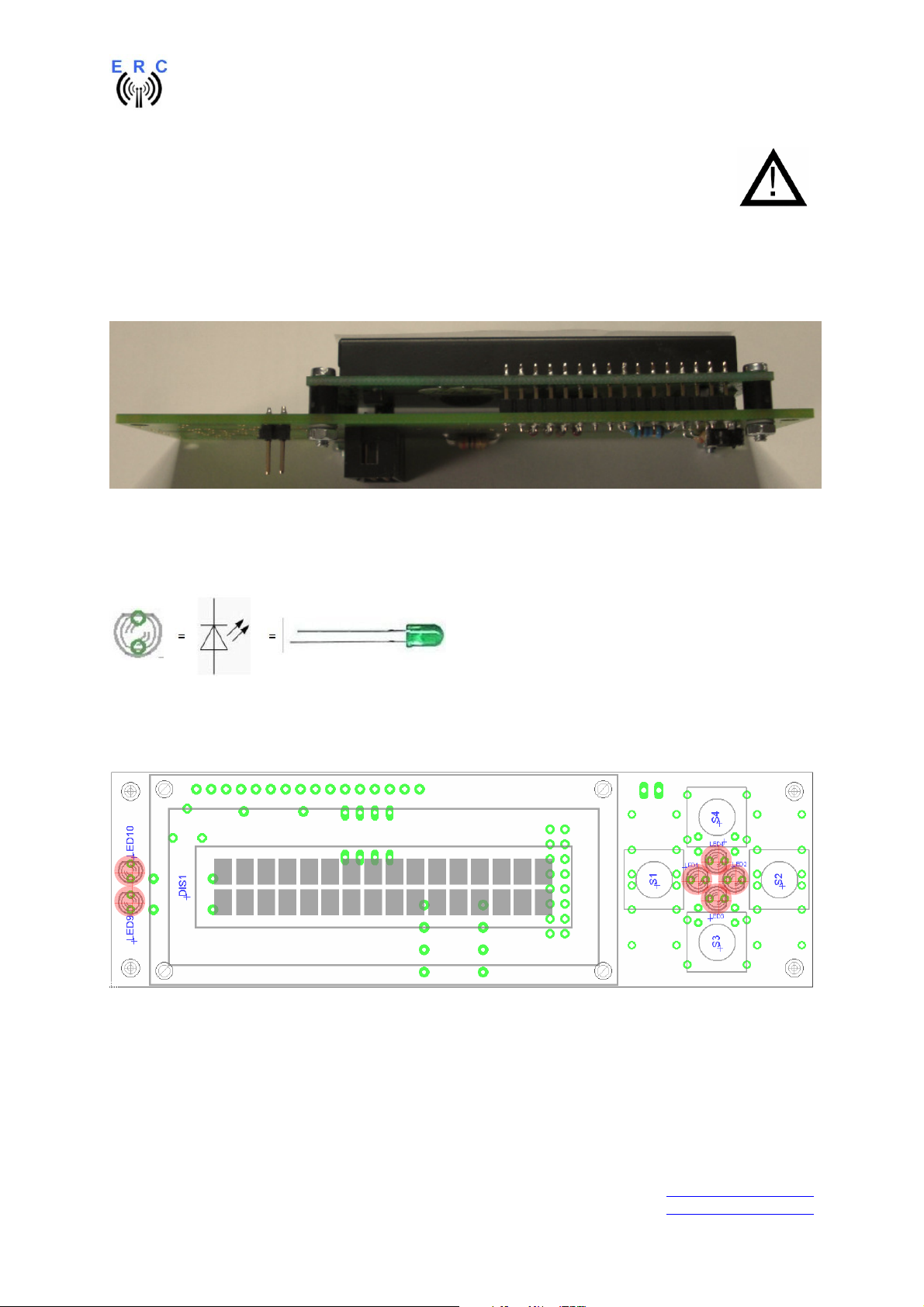
Take care of polarization of the following components :
- LED1,LED2,LED3,LED4,LED9,LED10
Those components are marked red in the following drawing.
Assemble and solder the switches and LEDs according to the following drawings.
Take care that the switches fit plane to the PCB. Otherwise you will have problems with sticky
switches later when the HID is mounted to the front-panel.
Hint: Only solder 1 leg of the switches and LEDs, check for alignment and than solder the remaining
pins.
___________________________________________________________________________
© Ing.-Büro E. Alba de Schmidt web : www.schmidt-alba.de
Tannenstr. 16 Page 33 of 44 email : erc@schmidt-alba.de
86836 Untermeitingen / Germany
This document is for the user only. Any publishing (printed or in electronic form) is not allowed.
Page 34
EASY-ROTOR-CONTROL M V2.2 Instructions
Use the 3x12x4mm spacers for the LEDs to fix them in the right distance from the PCB.
K
K
Put the 19mm domes on top of the switches.
This is how it should look like:
K
K
K
K
___________________________________________________________________________
© Ing.-Büro E. Alba de Schmidt web : www.schmidt-alba.de
Tannenstr. 16 Page 34 of 44 email : erc@schmidt-alba.de
86836 Untermeitingen / Germany
This document is for the user only. Any publishing (printed or in electronic form) is not allowed.
Page 35
EASY-ROTOR-CONTROL M V2.2 Instructions
Red wire on this side
Red wire on this side
Pin 1
Pin 1
male
female
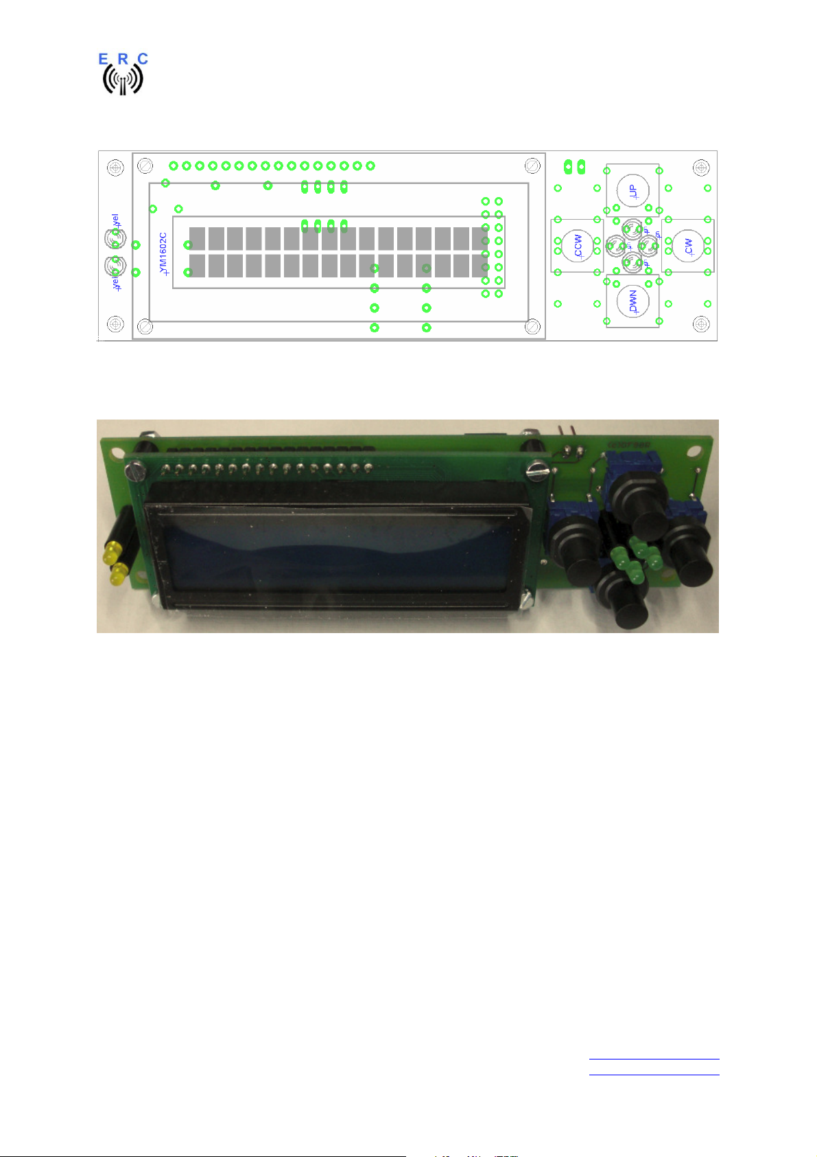
6.5 Cable to connect the HID to ERC-M
Cut 130mm from the flat-ribbon-cable and press the 2x8 pole connectors to both ends as shown in the
next picture.
Take care of the orientation of the connectors (red circle) and the position of the red wire.
Use a bench-vise to properly press the connectors to the flat-ribbon-cable.
Those connectors are quite sensible and may damage if you don’t press
them properly.
Bend the flat-ribbon-cable on both ends over the top of the connector and put the strain-relief on.
6.6 Cable to connect the ERC-M to rear-side D-SUB
Take the remaining 200mm of the flat-ribbon-cable and remove 1 wire from the 16-pole cable to get a
15-pole cable (don’t remove the red wire, take the opposite site)
Press the 2 DSUB-connectors to both ends as shown in the next picture. The red wire always has to
show to pin 1 of the connectors. The pin-number of the connectors is printed in the plastics of the
connectors.
___________________________________________________________________________
© Ing.-Büro E. Alba de Schmidt web : www.schmidt-alba.de
Tannenstr. 16 Page 35 of 44 email : erc@schmidt-alba.de
86836 Untermeitingen / Germany
This document is for the user only. Any publishing (printed or in electronic form) is not allowed.
Page 36
EASY-ROTOR-CONTROL M V2.2 Instructions
6.7 Mechanical integration into the desktop-housing
Mount the 4 rubber-feet to the desktop housing
using 4 screws 2.9x6.5mm.
Remove the protection-foil from the LCD and mount
the HID into the desktop-housing with 4 Allen-screws
using the Allen-tool provided with the kit.
Mount the ERC-M-PCB to the housing with Allenscrews.
Fold the 15-pole flat-ribbon-cable as shown and put
the DSUB-connectors as shown and mount the
female-DSUB-connector to the back-panel of the
housing with the 2 UNC-distance-bolts and 2 washers
from the DSUB-mounting kit.
___________________________________________________________________________
© Ing.-Büro E. Alba de Schmidt web : www.schmidt-alba.de
Tannenstr. 16 Page 36 of 44 email : erc@schmidt-alba.de
86836 Untermeitingen / Germany
This document is for the user only. Any publishing (printed or in electronic form) is not allowed.
Page 37
EASY-ROTOR-CONTROL M V2.2 Instructions
Attach the 16-pole flat-ribbon-cable into the
connectors as shown.
Connect the ERC-M to DC-supply or USB to check
contrast settings. After start-up you should see a
start-up-screen like this:
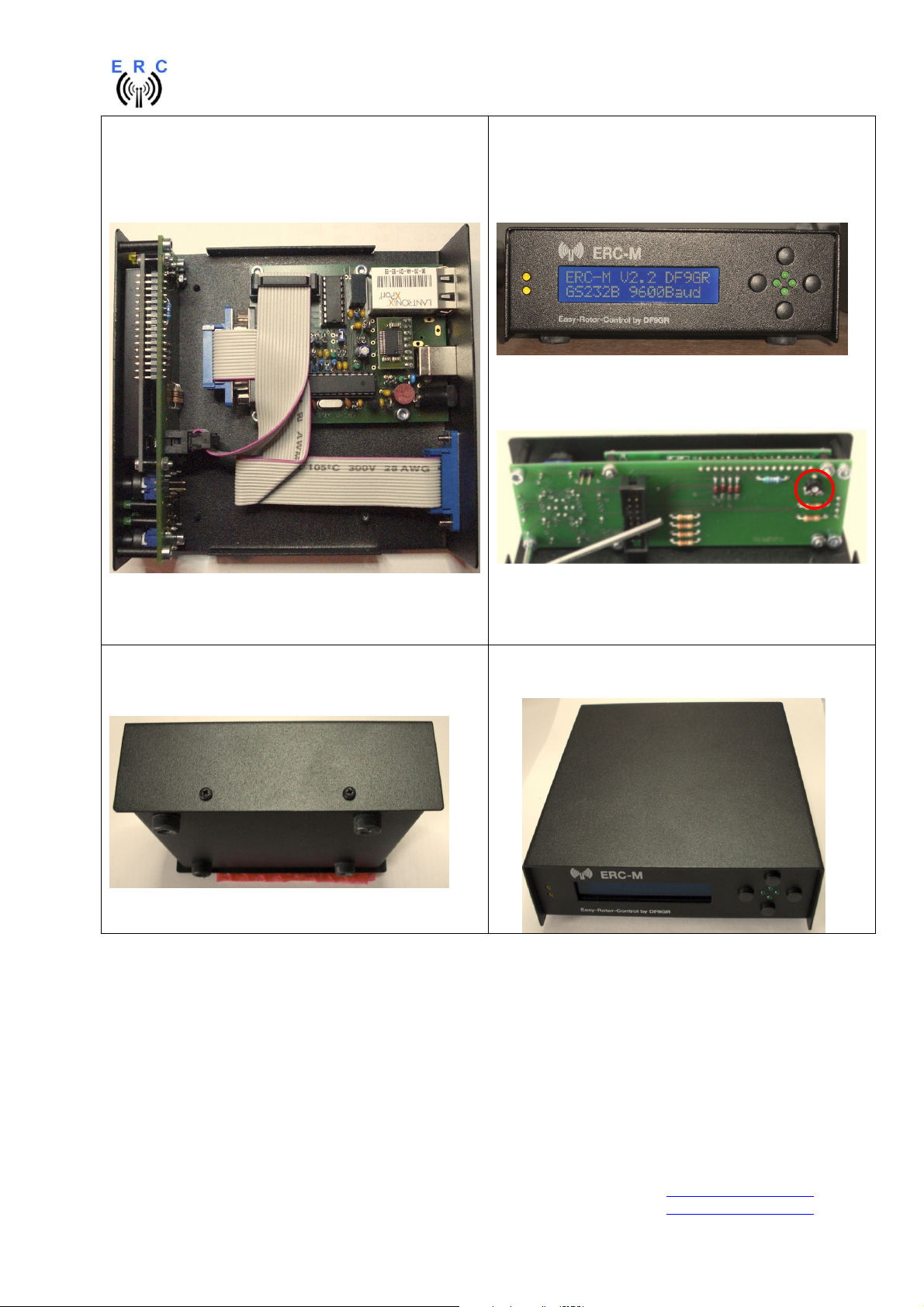
Put the top-cover onto the housing and fix it with 4
screws 2.9x6.5mm
Adjust the contrast with the potentiometer R1 on the
backside of the HID-PCB.
Here we are: READY to go
___________________________________________________________________________
© Ing.-Büro E. Alba de Schmidt web : www.schmidt-alba.de
Tannenstr. 16 Page 37 of 44 email : erc@schmidt-alba.de
86836 Untermeitingen / Germany
This document is for the user only. Any publishing (printed or in electronic form) is not allowed.
Page 38
EASY-ROTOR-CONTROL M V2.2 Instructions
7. The Service-Tool
The Service Tool is on the CD supplied with the kit.
Start the Setup-File SETUP ERC-M_Vnn.EXE (nn=version) directly on the CD and follow the
instructions.
The installation wizard will automatically install the Service Tool in the program directory (or any other
if you choose a different one) and put an icon on your desktop.
Start the Service Tool by double-clicking the Icon on the desktop.
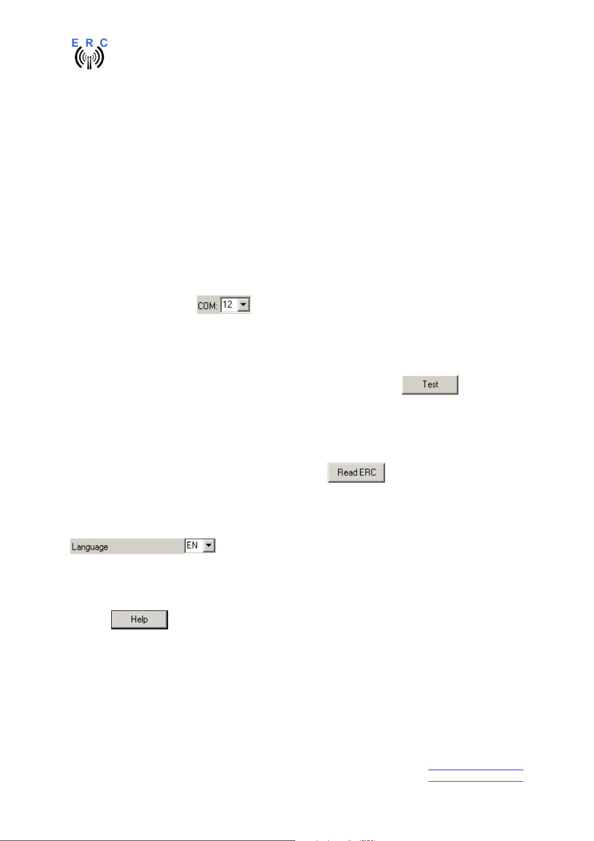
7.1 Configuration of the COM-Port
On shipment, the Service Tool is configured to COM1, which is most properly not the com-port, where
you connected the ERC-M, hence after Start-Up the program may bring up an error-message because
of the wrong COM-Port.
Choose the right COM-Port.
The Service Tool will check the availability of the ERC-M at the chosen COM-Port. If successful, the
Service Tool will read the configuration-parameters of the ERC-M and populates the configurationand the calibration-windows.
You can now perform a little hardware-test before the installation. Click the -button and all
LEDs on the HID-PCB and relays on the rotor-cards will be switched on sequentially.
7.2 Read the ERC-M-configuration-parameters
The parameters of the ERC-M can be read by clicking the button.
7.3 Language
The Service-Tool and the help-files are available in different languages. Choose the language with the
-box.
7.4 Other functions of the Service Tool
The other functions of the Service Tool are well described in the help-function of the Service Tool.
Click the button.
___________________________________________________________________________
© Ing.-Büro E. Alba de Schmidt web : www.schmidt-alba.de
Tannenstr. 16 Page 38 of 44 email : erc@schmidt-alba.de
86836 Untermeitingen / Germany
This document is for the user only. Any publishing (printed or in electronic form) is not allowed.
Page 39

EASY-ROTOR-CONTROL M V2.2 Instructions
8. Theory of operation
A Microcontroller receives commands via the RS232- or USB or LAN-interface in the Yaesu GS-232B
(or GS-232A) or DCU-1 protocol from the programs that support controlling rotators.
The ERC-M takes the task to move the rotator to the desired position or to stop the rotator while it is
moving. Also changes of the direction are possible while the rotator is moving. The current position of
the rotators is calculated from the measured rotor-feedback-voltages AZ and EL. To achieve accurate
function, the ERC-M has to be calibrated to the specific value of the rotor-feedback-voltages (ref. to
the next chapter).
Depending on the direction to move, the contacts CW and CCW or UP and DWN are tighten to
ground. With a programmable delay the contact AUX1 and AUX2 will be activated to control the speed
or the brake of the rotator.
The ERC-M is powered either the USB-bus, by the control-box it is connected to or by external
10..12VDC. The current consumption is according to the USB-specifications. Using an USB-hub may
require to power this hub. Wherever there is a suitable DC-supply available on the rotor-controllers
remote-jack, it is taken from there to supply the ERC-M. The ERC-M is than switching automatically to
the external supply in order not to drawn current from the USB-bus.
9. Calibration
After the ERC-M is connected to the rotor-controller, it has to be calibrated. This calibration is needed,
because different kinds of rotators deliver different kinds of feedback-voltages. Also variations
between rotators of the same model would lead to inaccuracy. To calibrate the ERC-M, it has to
measure the rotor-feedback-voltages at both ends including overlaps (turning radius > 360°). The
calibration is a software-guided procedure, which will be started by pressing the or
button of the service tool. Just follow the instructions given by the calibration assistant.
If the feedback-voltage of the rotator has unlineraities, an extended calibration can be performed every
30° for azimuth or every 15° for elevation by pressing the or button.
10. First check of calibration with Rotor-Control M
The rotor-control-program Rotor-Control M is on the CD supplied with the kit.
Start the Setup-File SETUP RC-M_Vnn.EXE directly on the CD and follow the instructions.
The installation wizard will automatically install the Service Tool in the program directory (or any other
if you choose a different one) and puts an icon on your desktop.
Set the ERC-M with the Service-Tool to Baudrate 9600 and Protocol GS232B.
Start Rotor-Control M by double-clicking the Icon on the desktop.
The green pointers and numbers show the current position of the rotators.
Targets can be put at the red numbers.
You can control the rotators for Azimuth and Elevation separately or together. Click the GO- or STOPbuttons.
You can also move a rotator to a target-position by clicking on any point of the graphics.
By clicking the button PARK, the rotators move to their configured parking positions.
___________________________________________________________________________
© Ing.-Büro E. Alba de Schmidt web : www.schmidt-alba.de
Tannenstr. 16 Page 39 of 44 email : erc@schmidt-alba.de
86836 Untermeitingen / Germany
This document is for the user only. Any publishing (printed or in electronic form) is not allowed.
Page 40
EASY-ROTOR-CONTROL M V2.2 Instructions
Rotor-Control M can be configured to work for a single-axis setup or a dual-axis setup.
AZ&EL AZ&AZ AZ only
11. Connect the ERC-M to other programs
Please take care about the following issues, if you want to control your ERC-M with other programs :
- Choose the right COM-port
- COM-port-speed in the program must be same as in ERC-M
o The speed of ERC-M is shown during the start-up on the LCD or in the service-tool
- Adjust the comport in the program to : N-8-1 (No Parity, 8 databits,1 stopbit)
- Use the same protocol in program and ERC-M (Yaesu GS232B, GS232A or Hygain DCU-1)
o The protocol of ERC-M is shown during the start-up on the LCD or in the service-tool
___________________________________________________________________________
© Ing.-Büro E. Alba de Schmidt web : www.schmidt-alba.de
Tannenstr. 16 Page 40 of 44 email : erc@schmidt-alba.de
86836 Untermeitingen / Germany
This document is for the user only. Any publishing (printed or in electronic form) is not allowed.
Page 41

EASY-ROTOR-CONTROL M V2.2 Instructions
Appendix
Appendix1: Pin-out of D-SUB15 ERC-M
Connector seen from outside to the female connector on ERC-M or on the back of the desktophousing.
Appendix2: Pin-out of mini-DIN rotor-card
Connector seen from outside to the female connector on the rotor-card.
Appendix3: Connection of rotor-card to ERC-M
Mini-DIN rotor-card Signal D-SUB ERC-M
axis 1
1 CW/UP 9 15
2 CCW/DOWN 2 7
3 AUX 11 13
4 Feedback-voltage 1 8
5 GND 10 14
6 DC-supply 12 12
D-SUB ERC-M
axis 2
___________________________________________________________________________
© Ing.-Büro E. Alba de Schmidt web : www.schmidt-alba.de
Tannenstr. 16 Page 41 of 44 email : erc@schmidt-alba.de
86836 Untermeitingen / Germany
This document is for the user only. Any publishing (printed or in electronic form) is not allowed.
Page 42

EASY-ROTOR-CONTROL M V2.2 Instructions
Appendix4: Pin-out of the HID-connector on ERC-M
2 4 6 8 10 12 14 16
1 3 5 7 9 11 13 15
Pin Pin
1 GND 9 LCD E
2 VCC 10 LCD RS
3 Keyboard Common 11 LED AUX2
4 +5V 12 LED AUX1
5 LCD D7, Keyboard UP 13 LED DWN
6 LCD D6, Keyboard DWN 14 LED UP
7 LCD D5, Keyboard CW 15 LED CCW
8 LCD D4, Keyboard CCW 16 LED CW
Appendix5: Schematics Rotor-Card
5
6
3
4
1 2
___________________________________________________________________________
© Ing.-Büro E. Alba de Schmidt web : www.schmidt-alba.de
Tannenstr. 16 Page 42 of 44 email : erc@schmidt-alba.de
86836 Untermeitingen / Germany
This document is for the user only. Any publishing (printed or in electronic form) is not allowed.
Page 43

EASY-ROTOR-CONTROL M V2.2 Instructions
Appendix6: Schematics ERC-M
___________________________________________________________________________
© Ing.-Büro E. Alba de Schmidt web : www.schmidt-alba.de
Tannenstr. 16 Page 43 of 44 email : erc@schmidt-alba.de
86836 Untermeitingen / Germany
This document is for the user only. Any publishing (printed or in electronic form) is not allowed.
Page 44

EASY-ROTOR-CONTROL M V2.2 Instructions
Appendix7: Schematics HID
___________________________________________________________________________
© Ing.-Büro E. Alba de Schmidt web : www.schmidt-alba.de
Tannenstr. 16 Page 44 of 44 email : erc@schmidt-alba.de
86836 Untermeitingen / Germany
This document is for the user only. Any publishing (printed or in electronic form) is not allowed.
 Loading...