

Page 1
EAG18-Li
MNL_EAG18-Li_V01_180608
EAN. 3663602799191
ORIGINAL INSTRUCTIONS
Page 2
Safety instructions
Product description
Assembly
Use
Care & maintenance
Guarantee
x1
WARNING!
that they are fully understood before handling the tool.
Please read all safety warnings carefully and be sure
Declaration of Conformity
2
3
Page 3
PRODUCT DESCRIPTION
6
5
2
1
3
101112
4
7
8
13
14
9
15
16
17
18
B C1
C2
14
15
16
D E
14
15
16
4
A1
1
A2
2
F G
5
Page 4
SAFETY INSTRUCTIONS
15° -30°
H
I
GENERAL POWER TOOL SAFETY WARNINGS
WARNING! Read all safety warnings, instructions,
illustrations and specications provided with this
power tool. Failure to follow all instructions listed below
may result in electric shock, re and/or serious injury.
Save all warnings and instructions for future
reference. The term “power tool” in the warnings refers
to your mains-operated (corded) power tool or battery
operated (cordless) power tool.”
WORK AREA SAFETY
a. K
eep work area clean and well lit. Cluttered or dark areas
invite accidents.
b. D
o not operate power tools in explosive atmospheres,
such as in the presence of ammable liquids, gases or dust.
Power tools create sparks which may ignite the dust or fumes.
c. K
eep children and bystanders away while operating a
power tool. Distractions can cause you to lose control.
ELECTRICAL SAFETY
a. Pow
er tool plugs must match the outlet. Never modify the
plug in any way. Do not use any adapter plugs with earthed
(grounded) power tools. Unmodied plugs and matching
outlets will reduce risk of electric shock.
b. Av
oid body contact with earthed or grounded surfaces,
such as pipes, radiators, ranges and refrigerators. There
is an increased risk of electric shock if your body is earthed or
grounded.
6
7
Page 5

c. Do n
ot expose power tools to rain or wet conditions. Water
entering a power tool will increase the risk of electric shock.
d. Do
not abuse the cord. Never use the cord for carrying,
pulling or unplugging the power tool. Keep cord away
from heat, oil, sharp edges or moving parts. Damaged or
entangled cords increase the risk of electric shock.
e. W
hen operating a power tool outdoors, use an
extension cord suitable for outdoor use. Use of a cord
suitable for outdoor use reduces the risk of electric shock.
f. If
operating a power tool in a damp location is unavoidable,
use a residual current device (RCD) protected supply. Use
of an RCD reduces the risk of electric shock.
PERSONAL SAFETY
a. St
ay alert, watch what you are doing and use common
sense when operating a power tool. Do not use a power tool
while you are tired or under the inuence of drugs, alcohol
or medication. A moment of inattention while operating power
tools may result in serious personal injury.
b. Use
personal protective equipment. Always wear eye
protection. Protective equipment such as a dust mask, non-
skid safety shoes, hard hat, or hearing protection used for
appropriate conditions will reduce personal injuries.
c. Pr
event unintentional starting. Ensure the switch is in the
off- position before connecting to power source and/or
battery pack, picking up or carrying the tool. Carrying power
tools with your nger on the switch or energising power tools
that have the switch on invites accidents.
d. Re
move any adjusting key or wrench before turning the
power tool on. A wrench or a key left attached to a rotating
part of the power tool may result in personal injury.
e. Do
not overreach. Keep proper footing and balance at
all times. This enables better control of the power tool in
unexpected situations.
f. Dre
ss properly. Do not wear loose clothing or jewellery.
Keep your hair, clothing away from moving parts. Loose
clothes, jewellery or longhair can be caught in moving parts.
g. If
devices are provided for the connection of dust
extraction and collection facilities, ensure these are
connected and properly used. Use of dust collection can
reduce dust-related hazards.
h. D
o not let familiarity gained from frequent use of tools
allow you to become complacent and ignore tool safety
principles. A careless action can cause severe injury within a
fraction of a second.
POWER TOOL USE AND CARE
a. D
o not force the power tool. Use the correct power tool for
your application. The correct power tool will do the job better
and safer at the rate for which it was designed.
b. D
o not use the power tool if the switch does not turn it
on and off. Any power tool that cannot be controlled with the
switch is dangerous and must be repaired.
c. Di
sconnect the plug from the power source and/or remove
the battery pack, if detachable, from the power tool before
making any adjustments, changing accessories, or storing
power tools. Such preventive safety measures reduce the risk
of starting the power tool accidentally.
d. S
tore idle power tools out of the reach of children and do
not allow persons unfamiliar with the power tool or these
instructions to operate
the power tool.
Power tools are
dangerous in the hands of untrained users.
e. M
aintain power tools and accessories. Check for
misalignment or binding of moving parts, breakage of
parts and any other condition that may affect the power
tools operation. If damaged, have the power tool repaired
before use. Many accidents are caused by poorly maintained
power tools.
8
9
Page 6

f. K
eep cutting tools sharp and clean. Properly maintained
cutting tools with sharp cutting edges are less likely to bind and
are easier to control.
g. Us
e the power tool, accessories and tool bits etc. in
accordance with these instructions, taking into account
the working conditions and the work to be performed. Use
of the power tool for operations different from those intended
could result in a hazardous situation.
h. K
eep handles and grasping surfaces dry, clean and free
from oil and grease. Slippery handles and grasping surfaces
do not allow for safe handling and control of the tool in
unexpected situations.
BATTERY TOOL USE AND CARE
a. R
echarge only with the charger specied by the
manufacturer. A charger that is suitable for one type of battery
pack may create a risk of re when used with another battery
pack.
b. U
se power tools only with specically designated battery
packs. Use of any other battery packs may create a risk of
injury and re.
c. When
battery pack is not in use, keep it away from other
metal objects, like paper clips, coins, keys, nails, screws
or other small metal objects, that can make a connection
from one terminal to another. Shorting the battery terminals
together may cause burns or a re.
d. Unde
r abusive conditions, liquid may be ejected from the
battery; avoid contact. If contact accidentally occurs,
ush with water. If liquid contacts eyes, additionally seek
medical help. Liquid ejected from the battery may cause
irritation or burns.
e. Do
not use battery pack or tool that is damaged or
modied. Damaged or modied batteries may exhibit
unpredictable behaviour resulting in re, explosion or risk of
injury.
10
f. Do
not expose a battery pack or tool to re or excessive
temperature. Exposure to re or temperature above 130 °C
may cause explosion.
g. Fo
llow all charging instructions and do not charge the
battery pack or tool outside the temperature range
specied in the instructions. Charging improperly or at
temperatures outside the specied range may damage the
battery and increase the risk of re.
SERVICE
a. Ha
ve your power tool serviced by a qualied repair person
using only identical replacement parts. This will ensure that
the safety of the power tool is maintained.
b. N
ever service damaged battery packs. Service of battery
packs should only be performed by the manufacturer or
authorized service providers.
ADDITIONAL SAFETY INSTRUCTIONS FOR YOUR ANGLE
GRINDER:
SAFETY WARNINGS COMMON FOR GRINDING OR ABRASIVE
CUTTING-OFF OPERATIONS:
a This power tool is intended to function as a grinder
or cutoff tool. Read all safety warnings, instructions,
illustrations and specications provided with this power
tool. Failure to follow all instructions listed below may result in
electric shock, re and/or serious injury.
b Operations such as sanding, wire brushing, polishing are
not recommended to be performed with this power tool.
Operations for which the power tool was not designed may
create a hazard and cause personal injury.
c Do not use accessories which are not specically designed
and recommended by the tool manufacturer. Just because
the accessory can be attached to your power tool, it does not
assure safe operation.
11
Page 7

d The rated speed of the accessory must be at least equal to
the maximum speed marked on the power tool. Accessories
running faster than their rated speed can break and y apart.
e The outside diameter and the thickness of your accessory
must be within the capacity rating of your power tool.
Incorrectly sized accessories cannot be adequately guarded or
controlled.
f Threaded mounting of accessories must match the grinder
spindle thread. For accessories mounted by anges, the
arbour hole of the accessory must t the locating diameter
of the ange. Accessories that do not match the mounting
hardware of the power tool will run out of balance, vibrate
excessively and may cause loss of control.
i Keep bystanders a safe distance away from work area.
Anyone entering the work area must wear personal
protective equipment. Fragments of workpiece or of a broken
accessory may y away and cause injury beyond immediate
area of operation.
j Hold power tool by insulated gripping surfaces only, when
performing an operation where the cutting accessory may
contact hidden wiring. Cutting accessory contacting a “live”
wire may make exposed metal parts of the power tool “live” and
could give the operator an electric shock.
k Position the cord clear of the spinning accessory. If you
lose control, the cord may be cut or snagged and your hand or
arm may be pulled into the spinning accessory.
g Do not use a damaged accessory. Before each use inspect
the accessory such as abrasive wheels for chips and
cracks, backing pad for cracks, tear or excess wear. If
power tool or accessory is dropped, inspect for damage
or install an undamaged accessory. After inspecting and
installing an accessory, position yourself and bystanders
away from the plane of the rotating accessory and run
the power tool at maximum no-load speed for one minute.
Damaged accessories will normally break apart during this test
time.
h Wear personal protective equipment. Depending on
application, use face shield, safety goggles or safety
glasses. As appropriate, wear dust mask, hearing
protectors, gloves and workshop apron capable of
stopping small abrasive or workpiece fragments. The eye
protection must be capable of stopping ying debris generated
by various operations. The dust mask or respirator must be
capable of ltrating particles generated by your operation.
Prolonged exposure to high intensity noise may cause hearing
loss.
l Never lay the power tool down until the accessory has
come to a complete stop. The spinning accessory may grab
the surface and pull the power tool out of your control.
m Do not run the power tool while carrying it at your side.
Accidental contact with the spinning accessory could snag your
clothing, pulling the accessory into your body.
n Regularly clean the power tool’s air vents. The motor’s
fan will draw the dust inside the housing and excessive
accumulation of powdered metal may cause electrical hazards.
o Do not operate the power tool near ammable materials.
Sparks could ignite these materials.
p Do not use accessories that require liquid coolants. Using
water or other liquid coolants may result in electrocution or
shock.
12
13
Page 8

KICKBACK AND RELATED WARNINGS
Kickback is a sudden reaction to a pinched or snagged rotating
wheel, backing pad, brush or any other accessory. Pinching or
snagging causes rapid stalling of the rotating accessory which
in turn causes the uncontrolled power tool to be forced in the
direction opposite of the accessory’s rotation at the point of the
binding. For example, if an abrasive wheel is snagged or pinched
by the workpiece, the edge of the wheel that is entering into the
pinch point can dig into the surface of the material causing the
wheel to climb out or kick out. The wheel may either jump toward
or away from the operator, depending on direction of the wheel’s
movement at the point of pinching. Abrasive wheels may also
break under these conditions. Kickback is the result of power tool
misuse and/or incorrect operating procedures or conditions and
can be avoided by taking proper precautions as given below.
a Maintain a rm grip on the power tool and position your
body and arm to allow you to resist kickback forces.
Always use auxiliary handle, if provided, for maximum
control over kickback or torque reaction during start-up.
The operator can control torque reactions or kickback forces, if
proper precautions are taken.
b Never place your hand near the rotating accessory.
Accessory may kickback over your hand.
c Do not position your body in the area where power tool
will move if kick- back occurs. Kickback will propel the tool
in direction opposite to the wheel’s movement at the point of
snagging.
d Use special care when working corners, sharp edges etc.
Avoid bouncing and snagging the accessory. Corners,
sharp edges or bouncing have a tendency to snag the rotating
accessory and cause loss of control or kickback.
e Do not attach a saw chain woodcarving blade or toothed
saw blade. Such blades create frequent kickback and loss of
control.
14
SAFETY WARNINGS SPECIFIC FOR GRINDING AND
ABRASIVE CUTTING-OFF OPERATIONS:
a Use only wheel types that are recommended for your
power tool and the specic guard designed for the selected
wheel. Wheels for which the power tool was not designed
cannot be adequately guarded and are unsafe.
b The grinding surface of centre depressed wheels must be
mounted below the plane of the guard lip. An improperly
mounted wheel that projects through the plane of the guard lip
cannot be adequately protected.
c The guard must be securely attached to the power tool
and positioned for maximum safety, so the least amount
of wheel is exposed towards the operator. The guard helps
to protect operator from broken wheel fragments, accidental
contact with wheel and sparks that could ignite clothing.
d Wheels must be used only for recommended applications.
For example: do not grind with the side of cut-off wheel.
Abrasive cut-off wheels are intended for peripheral grinding,
side forces applied to these wheels may cause them to shatter.
e Always use undamaged wheel anges that are of correct
size and shape for your selected wheel. Proper wheel
anges support the wheel thus reducing the possibility of wheel
breakage. Flanges for cut-off wheels may be different from
grinding wheel anges.
f Do not use worn down wheels from larger power tools.
Wheel intended for larger power tool is not suitable for the
higher speed of a smaller tool and may burst.
ADDITIONAL SAFETY WARNINGS SPECIFIC FOR ABRASIVE
CUTTING-OFF OPERATIONS:
a Do not “jam” the cut-off wheel or apply excessive
pressure. Do not attempt to make an excessive depth
of cut. Overstressing the wheel increases the loading and
susceptibility to twisting or bind- ing of the wheel in the cut and
the possibility of kickback or wheel breakage.
15
Page 9

b Do not position your body in line with and behind the
rotating wheel. When the wheel, at the point of operation, is
moving away from your body, the possible kickback may propel
the spinning wheel and the power tool directly at you.
c When wheel is binding or when interrupting a cut for any
reason, switch off the power tool and hold the power
tool motionless until the wheel comes to a complete
stop. Never attempt to remove the cut-off wheel from the cut
while the wheel is in motion otherwise kickback may occur.
Investigate and take corrective action to eliminate the cause of
wheel binding.
d Do not restart the cutting operation in the workpiece. Let
the wheel reach full speed and carefully re-enter the cut.
The wheel may bind, walk up or kickback if the power tool is
restarted in the workpiece.
e Support panels or any oversized workpiece to minimize
the risk of wheel pinching and kickback. Large workpieces
tend to sag under their own weight. Supports must be placed
under the workpiece near the line of cut and near the edge of
the workpiece on both sides of the wheel.
f Use extra caution when making a “pocket cut” into existing
walls or other blind areas. The protruding wheel may cut
gas or water pipes, electrical wiring or objects that can cause
kickback.
ADDITIONAL SAFETY WARNINGS FOR BATTERY
a.
Do not connect the positive terminal and negative terminal of
the battery to each other with any metal object (such as wire).
b.
Do not carry or store battery together with necklaces, hairpins
or other metal objects.
c.
Do not pierce the battery with nails, strike the battery with a
hammer, step on the battery or otherwise subject it to strong
impacts or shocks.
d.
Do not solder directly onto the battery.
e.
Do not expose battery to water or salt water, or allow the
battery to get wet.
f.
Do not disassemble or modify the battery.
g.
Do not place the battery in or near re, on stoves or other
high temperature locations. Do not place the battery in direct
sunlight, or use or store the battery inside cars in hot weather.
h.
Do not place the battery in microwave ovens, high-pressure
containers or on induction cookware.
i.
If you intend to store a battery for a period without use then store
battery at room temperature (19°C to 25°C), charged to about
30 – 50% of capacity. When storing for very long periods boost
charge the battery once per year to prevent over discharge.
The following information applies to professional users only but is
good practice for all users:
ADDITIONAL SAFETY WARNING FOR CONSTRUCTION DUST
The updated Control of Substances Hazardous to Health
Regulations 1st October 2012 now also targets to reduce the
risks associated with silica, wood and gypsumdusts. Construction
workers are one of the at-risk groups within this because of the
dust that they breathe: silica dust is not just a nuisance; it is a real
risk to your lungs!
Silica is a natural mineral present in large amounts in things like
sand, sandstone and granite. It is also commonly found in many
construction materials such as concrete and mortar. The silica is
broken into very ne dust (also known as Respirable Crystalline
Silica or RCS) during many common tasks such as cutting, drilling
and grinding. Breathing in very ne particles of crystalline silica
can lead to the development of: Lung cancer Silicosis Chronic
Obstructive Pulmonary Disorder/Chronic obstructive pulmonary
disease (COPD) And breathing in ne particles of wood dust can
lead to the development of Asthma. The risk of lung disease is
linked to people who regularly breathe construction dust over a
period of time, not on the odd occasion.
16
17
Page 10

To protect the lung, the COSHH Regulations sets a limit on the
amount of these dusts that you can breathe (called a Workplace
Exposure Limit or WEL) when averaged over a normal working
day. These limits are not a large amount of dust: when compared
to a penny it is tiny – like a small pinch of salt: This limit is the legal
maximum; the most you can breathe after the right controls have
been used.
WARNING! Some dust particles created by power
sanding, sawing, grinding, drill and other construction
jobs contain chemicals known to cause cancer, birth
defects or other reproductive harm. Some examples of
these chemicals are:
• Lead from lead-based paints.
HOW TO REDUCE THE AMOUNT OF DUST?
1. Reduce the amount of cutting by using the best sizes of building
products. Use a less powerful tool e.g. a block cutter instead of
angle grinder.
2. Using a different method of work altogether – e.g. using a nail
gun to direct fasten cable trays instead of drilling holes rst.
3. Please always work with approved safety equipment, such
as those dust masks that specially designed to lter out
microscopic particles and use the dust extraction facility at all
time.
For more information please see the HSE website: http://www.hse.
gov.uk/construction or http://www.hse.gov.uk/pubns/cis69.pdf
• Crystalline silica from bricks and cement and other
masonry products.
• Arsenic and chromium from chemically treated timber.
• Your risk from these exposures varies, depending
upon how often you do this type of work. To reduce
your exposure to these chemicals:
• Work in a well-ventilated area.
• Work with approved safety equipment, such as
those dust masks that are specially designed to lter
microscopic particles
VIBRATION
The European Physical Agents (Vibration) Directive has been
brought in to help reduce hand arm vibration syndrome injuries to
power tool users. The directive requires power tool manufacturers
and suppliers to provide indicative vibration test results to enable
users to make informed decisions as to the period of time a power
tool can be used safely on a daily basis and the choice of tool.
SEE TECHNICAL SPECIFICATIONS IN THE INSTRUCTION
MANUAL FOR THE VIBRATION LEVELS OF YOUR TOOL.
18
The declared vibration emission value should be used as a
minimum level and should be used with the current guidance on
vibration.
Calculating the actual period of use can be difcult and the HSE
website has further information.
19
Page 11

The declared vibration emission been measured in accordance
with EN60745-1,EN60745-2-3 and may be used to compare one
tool with another tool. The declared vibration emission value may
also be used in preliminary assessment of exposure.
WARNING! The vibration emission value during actual
use of the power tool can differ from the declared
value depending on the ways in which the tool is
used dependant on the following examples and other
variations on how the tool is used:
• How the tool is used and the materials being cut or
drilled.
Avoid using tools in temperatures of 10ºC or less. Plan your work
schedule to spread any high vibration tool use across a number of
days.
NOTE: The use of other tools will reduce the users’ total
working period on this tool.
HEALTH SURVEILLANCE
All employees should be part of an employer’s health surveillance
scheme to help identity any vibration related diseases at an early
stage, prevent disease progression and help employees stay in
work.
• The tool being in good condition and well maintained.
• Use the correct accessories for the tool and ensure
they are sharp and in good condition.
• The tightness of the grip on the handles.
• The tool is being used as intended by its design and
these instructions.
WARNING! Identify safety measures to protect the
operator that are based on an estimation of exposure in
the actual conditions of use (taking account of all parts
of the operating cycle such as the times when the tool is
switched off and when it is running idle in addition to the
trigger time).
While working with this power tool, hand/arm vibrations occur.
Adopt the correct working practices in order to reduce the
exposure to vibration. This tool may cause hand-arm vibration
syndrome if its use is not adequately managed.
Helping to minimise your vibration exposure risk. ALWAYS use sharp
chisels, drills and blades. Maintain this tool in accordance with
these instructions and keep well lubricated (where appropriate).
RESIDUAL RISKS
Even if you are operating this product in accordance with all
the safety requirements, potential risks of injury and damage
remain. The following dangers can arise in connection with
the structure and design of this product:
1. Injuries and damage to property due to broken attachments or
the sudden impact of hidden objects during use.
2. Danger of injury and property damage caused by ying objects
or poor power tool accessories.
20
21
Page 12

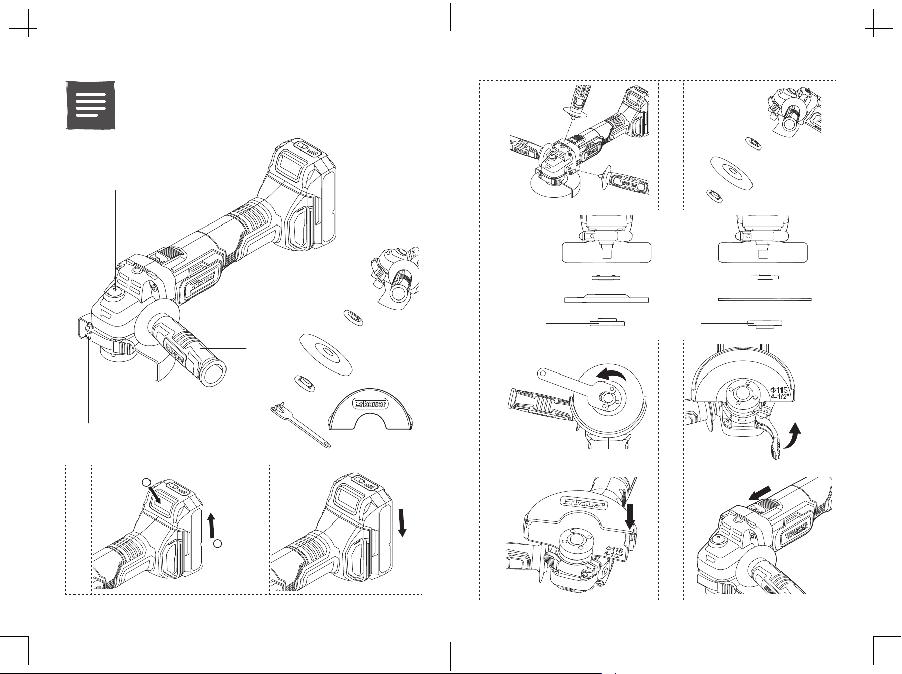
PRODUCT DESCRIPTION
1. Spindle lock button
2. Mounting threads (×3)
3. ON /OFF switch
4. Gripping surface
5. Battery pack release button
6. Power bar button
7. Battery pack (not included)
8. Filter cover (×2)
9. Auxiliary handle
TECHNICAL SPECIFICATIONS
01
Rated voltage: 18V d.c.
Rated speed n: 8500/min
Spindle thread M14
Maximum wheel diameter Ø115mm(4 1/2”)
Maximum thickness of grinding wheel 6mm
Wheel bore Ø22.23mm
Weight (without battery): 1.8 kg
Ambient temperature range for tool and battery use: -10°C to 40°C
For use with battery pack and charger as below:
Battery pack model: EBAT18-Li-2 / EBAT18-Li-4 / EBAT18-Li-5
Charger model: EC18-Li / EFC18-Li / EMC18-Li
NOISE DATA
A weighted sound pressure: L
A weighted sound power: L
Uncertainty: K
The noise for the operator may exceed 80 dB(A) and ear protection measures are
necessary.
VIBRATION DATA
Surface grinding a
Uncertainty K =1.5m/s²
10. Grinding safety guard
11. Guard clamping lever
12. Clamp adjustment screw
13. Spindle
14. Inner ange
15. Grinding/Cutting wheel (not included)
16. Outer ange
17. Spanner
18. Cutting safety guard
: 82.0dB (A)
pA
: 93.0dB (A)
wA
& KWA=3.0dB(A)
PA
=2.8m/s²
h,AG
RATING LABEL EXPLANATION
EAG18-Li=MODEL NUMBER E=Erbauer
AG=Angle Grinder
18 = 18V d.c.
Li = LITHIUM ION
22
23
Page 13

SYMBOLS
01
ASSEMBLY
Read the instruction manual
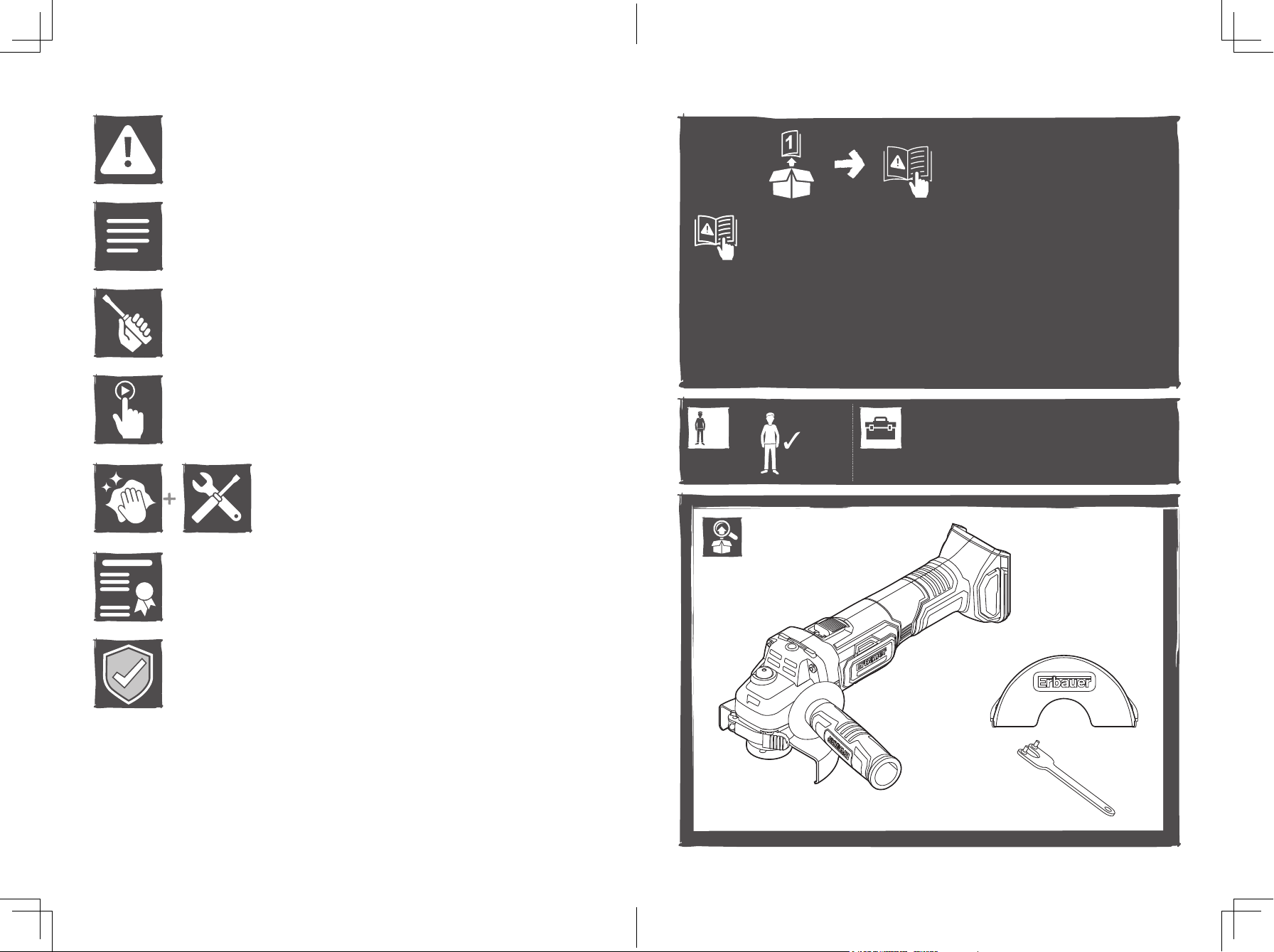
UNPACKING
02
Unpack all parts and lay them on a at, stable surface.
• Remove all packing materials and shipping devices, if applicable.
• Make sure the delivery contents are complete and free of any damage. If you nd that parts
are missing or show damage do not use the product but contact your dealer. Using an
incomplete or damaged product represents a hazard to people and property.
• Ensure that you have all the accessories and tools needed for assembly and operation. This
also includes suitable personal protective equipment
Wear eye protection
Wear hearing protection.
Wear a dust mask.
Do not dispose of battery packs in rivers or immerse in water.
Do not dispose of battery packs in re. They will explode and cause
injury.
Do not expose battery packs to heat in excess of 40°C
Brushless motor
WARNING!
Children must not play with plastic bags, sheets and small parts! There is a
danger of choking and suffocation!
ASSEMBLING THE MACHINE
03
The product and the packaging are not children’s toys!
CHARGING YOUR BATTERY PACK
The battery has been shipped in a low charge condition. Charge it fully before rst use.
Refer to the charger instruction manual for the details.
TO REMOVE OR INSTALL THE BATTERY PACK (A1, A2)
Depress the battery pack release button to release and slide the battery pack out from
your tool. After recharge, slide it back into your tool. A simple push and slight pressure will
be sufcient.
BATTERY PACK POWER BAR
This Li-Ion battery pack (7) is equipped with a POWER BAR which is used to give an
indication of the battery pack’s remaining charge. Press the POWER BAR button (6) to
check battery charge as below. The LED will stay lit for approximately 5 seconds
.
76-100% Charge
51-75% Charge
24
yyWxx
Keep Cool Battery Technology
Manufacturing date code: Year of manufacturing (20yy) and week
of manufacturing (Wxx)
6
Flash On Off
26-50% Charge
5-25% Charge
under 5% Charge
25
Page 14

AUXILIARY HANDLE ( B).
For all work with the machine, the auxiliary handle (9) must be mounted. Screw the
auxiliary handle (9) in one of the mounting threads (2) of the machine head depending on
the working method.
WARNING!
continue to use an auxiliary handle if it is damaged
Do not make any alterations to the auxiliary handle. Do not
To fasten the safety guard (10), close the clamping lever and loosen the clamp
adjustment screw (12), if necessary. The closed side of the safety guard (10) must
always point to the operator.
NOTE:
can be adjusted to ensure the guard is securely clamped after the clamping
lever (11) is nally closed.
With the clamping lever (11) open the clamp adjustment screw (12)
MOUNTING THE GRINDING/CUTTING WHEELS
Before any work on the machine itself, remove the battery pack.
Grinding and cutting wheels become very hot while working; do not touch until they have
cooled.
1. Spindle lock button
Clean the grinder spindle and all parts to be mounted. For clamping and loosening the
wheels, lock the grinder spindle (13) with the spindle lock button (1).
WARNING!
spindle is at a standstill!
2. Adjustable outer ange clamping ( C1, C2).
The outer ange (16) should be adjusted to suit different wheel thickness. For thinner
cutting or diamond discs the raised part of the outer ange is tted facing away from the
disc. For thicker grinding wheels the raised part of the outer ange is tted facing towards
the wheel to provide improved support for the wheel hole. Always ensure your wheel is
securely clamped.
3. Grinding/Cutting wheel ( D).
Pay attention to the dimensions of the grinding/cutting wheel. The mounting hole
diameter must t the inner ange (14) without play. Do not use reducers or adapters.
When using a diamond cutting disc, take care that the direction-of-rotation arrow on the
diamond cutting disc and the direction of rotation of the machine (direction-of rotation
arrow on the machine head) agree
Screw on the outer ange (16) and tighten with the two-pin spanner (17).
Actuate the spindle lock button (1) only when the grinder
WHEEL GUARD FOR CUTTING ( F)
WARNING!
cutting. For grinding, always work with the wheel guard for grinding.
For cutting-off application, position the front cover with the closed side on the grinding
guard and push it on until it engages
For cutting metal, always work with the wheel guard for
.
.
ADJUSTING THE SAFETY GUARD ( E).
For work with grinding or cutting wheels, the safety guard must be mounted.
Open the clamping lever (11). Place the safety guard (10) with coded projection into the
coded groove on the spindle of the machine head and rotate to the required position
(working position).
26
27
Page 15

Cutting (I)
3.
USE
INTENDED USE
01
The machine is intended for cutting and grinding metal and stone materials without using
water. For cutting, a special safety guard for cutting (accessory) must be used.
OPERATION
02
OPERATING INSTRUCTIONS
• Clamp the workpiece if it does not remain stationary due to its own weight.
• Do not strain the machine so heavily that it comes to a standstill.
• Grinding and cutting wheels become very hot while working; do not touch until
they have cooled.
STARTING OPERATION (G)
To start the power tool, press the rear of the on/off switch (3) and push forwards.
To lock the on/off switch, press the on/off switch down at the front until it engages.
To switch off the power tool, release the on/off switch or, if it is locked, briey push down
the back of the on/off switch and then release it.
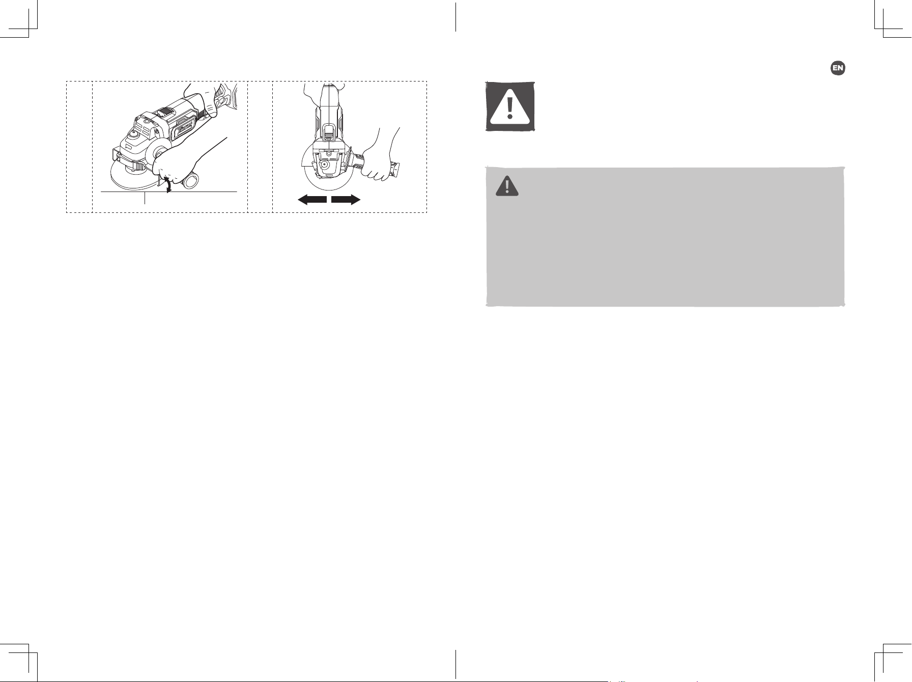
Hand grip areas
1.
Always hold your angle grinder rmly with both hands when operating (H).
Grinding (H)
2.
The best grinding results are achieved when setting the machine at an angle of 15°
to 30°. Move the machine back and forth with moderate pressure. In this manner, the
workpiece will not become too hot, does not discolour and no grooves are formed.
When cutting, do not press, tilt or oscillate the machine. Work with moderate feed,
adapted to the material being cut.
Do not reduce the speed of running down cutting discs by applying sideward pressure.
The direction in which the cutting is performed is important. The machine must always
work in an up-grinding motion. Therefore, never move the machine in the other direction!
Otherwise, the danger exists of it being pushed uncontrolled out of the cut.
WARNING!
cutting.
For cutting metal, always work with the wheel guard for
WORKING HINTS FOR YOUR ANGLE GRINDER
If your power tool becomes too hot, run no load for 2-3 minutes to cool the motor. Never
start your angle grinder with the disc/ accessory in contact with the workpiece. Always
start at no load to achieve maximum speed then start working.
Do not force the disc to work faster, reducing the disc’s moving speed means longer
working time.
When grinding, always work with a 30° to 40° angle between disc and workpiece. Larger
angles will cut ridges into the workpiece and affect the surface nish. Move the angle
grinder across and back and forth over the workpiece.
When using a cutting disc, never change the cutting angle otherwise you will stall the
disc and angle grinder motor or break the disc.
When cutting, only cut in the opposite direction to the disc rotation. If you cut in the same
direction as the disc rotation the disc may push itself out of the cut slot.
When cutting very hard material best results can be achieved with a diamond disc. When
using a diamond disc it will become very hot. If this happens you will see a full ring of
sparks around the rotating disc. Stop cutting and allow cooling at no load speed for 2-3
minutes.
Always ensure the workpiece is rmly held or clamped to prevent movement.
28
WARNING!
Never use a cutting wheel for grinding.
29
Page 16

OVERLOAD, TEMPERATURE AND CHARGING PROBLEM
Problem Tool/ Battery Status Possible cause Solution
Overload
protection
Temperature
extremely high
Low charge Power for the tool will
Other
problems
Product suddenly
Stops; The LED
work light (if tted) is
ashing
The rst and the
third LED light of the
POWER BAR will be
ashing alternately
drop quickly; The rst
LED on the POWER
BAR begins to ash
Short charges Not fully charged Make sure that the
Extremely high
torque, binding and
stalling situations,
overloading of the tool
Battery temperature
exceeds 77°C during
operation
The battery pack is
under 5% charge
Poor storage
condition
Relieve the load
immediately, reset the
tool by switching off and
back on again.
Cool down the battery to
below 77°C for operation
and below 57°C for
charging.
Remove the battery
pack from the tool and
charge it
battery is fully charged
every time by allowing
the charger to complete
its full charging cycle
Always remove battery
from the tool and
charger when not in use
and store in a dry secure
place. Avoid charging
or storing your battery
in temperatures below
5°C and above 40°C.
Cool down a hot battery
pack from a tool that
has just been operated
for approximately 30
minutes before storage
CARE & MAINTENANCE
MAINTENANCE
Your tool requires no additional lubrication or maintenance. There are no user serviceable
parts in your power tool. Never use water or chemical cleaners to clean your power tool.
Wipe clean with a dry cloth. Always store your power tool in a dry place. Keep the motor
ventilation slots clean. Keep all working controls free of dust.
RECYCLING AND DISPOSAL
Waste electrical products should not be disposed of with household waste.
Please recycle where facilities exist. Check with your Local Authority or retailer
for recycling advice.
For further information visit www.recycle-more.co.uk
DISPOSAL OF AN EXHAUSTED BATTERY PACK
To preserve natural resources, please recycle or dispose of the battery pack
properly. This battery pack contains Li-Ion batteries. Consult your local waste
authority for information regarding available recycling and/or disposal options.
Discharge your battery pack by operating your tool, then remove the battery pack
from the tool housing and cover the battery pack connections with heavy-duty
adhesive tape to prevent short circuit and energy discharge. Do not attempt to
open or remove any of the components.
REPAIR
This product does not contain any parts that can be repaired by the consumer. Contact an
authorised service centre or a similarly qualied person to have it checked and repaired.
STORAGE
• Switch the product off and remove the battery pack.
• Clean the product as described above.
• Store the product and its accessories in a dark, dry, frost-free, well- ventilated place.
• Always store the product in a place that is inaccessible to children.
• We recommend using the original package for storage or covering the product with a
suitable cloth or enclosure to protect it against dust.
TRANSPORTATION
• Switch the product off and remove the battery pack.
• Attach transportation guards, if applicable.
• Always carry the product by its handle.
• Protect the product from any heavy impact or strong vibrations which may occur during
transportation in vehicles.
• Secure the product to prevent it from slipping or falling over.
30
31
Page 17

GUARANTEE
At Erbauer we take special care to select high quality materials and use manufacturing
techniques that allow us to create ranges of products incorporating design and durability.
That’s why we offer a 2 year trade guarantee against manufacturing defects on our
Erbauer power tool products.
This power tool is guaranteed for 2 years from the date of purchase, if bought in store,
delivered or bought online. You may only make a claim under this guarantee upon
presentation of your sales receipt or purchase invoice. Please keep your proof of
purchase in a safe place.
This guarantee covers product failures and malfunctions provided the Erbauer power
tool was used for the purpose for which it is intended and subject to installation, cleaning,
care and maintenance in accordance with standard practice and with the information
contained above and in the user manual. This guarantee does not cover defects and
damage caused by or resulting from:
• Normal wear and tear, including accessory wear
• Overload, misuse or neglect
• Repairs attempted by anyone other than an authorised agent
• Cosmetic damage
• Damage caused by foreign objects, substances or accidents
• Accidental damage or modication
• Failure to follow manufacturer’s guidelines
• Loss of use of the goods
This guarantee is limited to parts recognised as defective. It does not, in any case, cover
ancillary costs (movement, labour) and direct and indirect damage.
If the Erbauer power tool is defective during the guarantee period, then we reserve
the right, at our discretion, to replace the item with a product of equivalent quality and
functionality or to provide a refund.
This guarantee only applies to the country of purchase or delivery and is not transferrable
to any other countries. This guarantee is non-transferrable to any other person or
product. Relevant local law will apply to this guarantee.
Guarantee related queries should be addressed to a store afliated with the distributor
you purchased the Erbauer power tool from.
This guarantee is in addition to and does not affect your statutory rights relating to faulty
goods as a consumer.
DECLARATION OF CONFORMITY
EU Declaration of Conformity
Kingsher International Products Limited
Declare that the product:
Erbauer 18V cordless angle grinder EAG18-Li
Serial number 00001-99999
Complies with the essential health and safety requirements of the following directives:
2006/42/EC The Machinery Directive
References to the following harmonized standard were made:
EN 60745-1:2009 + A11:2010
EN 60745-2-3:2011+A2:2013+A11:2014+A12:2014+A13:2015
2014/30/EU Electromagnetic Compatibility directive
References to the following harmonized standard were made:
(EU) 2015/863 amending 2011/65/EU Restrictions of the Use of Certain Hazardous Substances in
Electrical and Electronic Equipment
Authorised signatory and technical le holder:
Kingsher International Products Limited
We
3 Sheldon Square
London W2 6PX
United Kingdom
EN55014-1:2017
EN55014-2:2015
3 Sheldon Square
London W2 6PX
United Kingdom
on: 18/06/2018
Lisa Davis
Group Quality Director
32
33
Page 18

Page 19

Manufacturer • Fabricant • Producent • Hersteller • Producator • Fabricante:
Kingsher International Products Limited
3 Sheldon Square London W2 6PX
United Kingdom
www.kingsher.com/products
DISTRIBUTOR:
B&Q plc,
Chandlers Ford, Hants, SO53 3LE
United Kingdom
www.diy.com
Screwx Direct Limited,
Trade House, Mead Avenue,
Yeovil, BA22 8RT, United Kingdom
www.screwx.com
To view instruction manuals online,
visit www.kingsher.com/products
 Loading...