

Page 1
Always Moving Forward
®
Operating Manual
Please Read Before Operating Unit
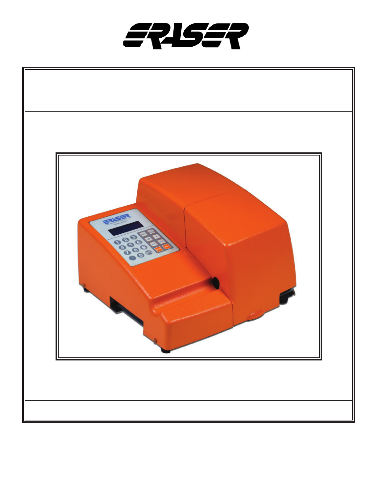
Model WC601A Wire & Tubing Cutter
The Eraser Company, Inc.
PO Box 4961/ Oliva Drive
Syracuse, NY 13221, USA
Please Call for Service or Spare Parts
Phone: (315) 454-3237
Fax: (315) 454-3090
Website: www.eraser.com
E-mail: [email protected]
Page 2
Always Moving Forward®
p 2
MODEL WC601A AUTOMATIC
WIRE & TUBING CUTTER
SPECIFICATIONS
Maximum cut length ................ 99,999” or 99,999 cm
Minimum cut length ............................. 0.1” (0.25 cm)
Maximum material size:
Tubing .............3/8” (9.5mm) OD; material dependent
Wire ...............................10AWG (2.58mm) stranded,
or 12AWG (2.05mm) solid
Accuracy ......................1% or better, up to +/- 0.005”;
material and feed dependent
Batching...................up to 99 programmable batches
Blade .....................Hardened and Ground Tool Steel
Power ................................................................ 120V
Air .............................................. up to 90PSI (6.2bar)
Size............14” x 13” x 8.75” (36cm x 46cm x 23cm)
Weight .................................................24lbs.(10.9kg)
Feed rates ......... 10 feed rates (see table on page 6)
Production rates (in pieces per hour) at various feed rates
Feedrate # /
Length
0 5,792 4,129 2,009 1,327 718 154
1 6,058 4,411 2,571 1,935 1,196 295
2 6,963 5,354 3,363 2,613 1,679 435
3 8,042 6,495 4,359 3,410 2,207 578
4 8,366 6,843 4,689 3,781 2,549 707
5 8,533 7,024 4,858 3,992 2,801 827
6 8,731 7,240 5,062 4,192 3,032 943
7 8,822 7,339 5,157 4,279 3,180 1,049
8 8,822 7,339 5,157 4,279 3,237 1,140
9 8,822 7,339 5,157 4,279 3,251 1,183
1” 2” 6” 10” 20” 100”
ORDERING INFORMATION
AR7121 Variable Speed Wire & Tubing Cutter
...........................................120V, 60Hz, Up to 90 PSI
INCLUDED PARTS
The WC601A ships with the following parts/tools:
- Qty 1 of 5/64” allen wrench for the entrance
bushing & feed belt pulley set screws (Part:
TG3028)
- Qty 1 of 3/32” allen wrench for the exit chute screw,
and cut (exit) bushing (Part: TG3790)
- Qty 2 of part PR0232 feed belt (installed)
- Qty 1 of part IR5161 wire cut blade (installed)
- Qty 1 of part PR2727 IEC power cord
OPTIONAL PARTS/ACCESSORIES
AR0010 (DE100) ..........................Turntable Dereeler
AR3801 (DE400) .............................Vertical Dereeler
AR0170 (DE700) ................. Compensating Dereeler
IR5162 ............................ Carbide Wire Cutting Blade
IR5218 .....................Tube Cutting Blade (Tool Steel)
PR0003.............................Regulator/Filter/Lubricator
PR1068...........................One Nitrile coated feed belt
(FDA Applications) (2 required per unit)
PR0733....................... One polyurethane coated belt
(“Grabber” belt) (2 required per unit)
REQUIRED PARTS
IR0755 ............ Standard bushing set 1/8” (3.175mm)
IR0756 ................ Standard bushing set 1/4” (6.3mm)
IR0757 .............. Standard bushing set 3/8” (9.53mm)
IR0903 ..................... Custom bushings 1/64” to 1/32”
(.381mm - .793mm)
IR0765 ................. Custom bushing set 1/32” to 1/16”
(.793mm - 1.59mm)
IR0764 ................... Custom bushing set 1/16” to 1/8”
(1.60mm - 3.175mm)
IR0763 ..................... Custom bushing set 1/8” to 3/8”
(3.175mm - 9.525mm)
Eraser Company Inc. • Syracuse, NY USA • Ph: 315-454-3237 • [email protected] • www.eraser.com • Fax 315-454-3090
REPLACEMENT PARTS
IR5161 .......Standard Wire Cutting Blade (Tool Steel)
PR0232............................ Single Standard Feed Belt
(2 required per unit)
Page 3

MODEL WC601A AUTOMATIC WIRE & TUBING CUTTER
p 3
IMPORTANT SAFETY INSTRUCTIONS
IMPORTANT! DO NOT OPERATE MACHINE
UNTIL YOU HAVE READ THOROUGHLY,
AND UNDERSTAND COMPLETELY, ALL
PRECAUTIONS, INSTRUCTIONS AND
INFORMATION ON THESE PAGES. THIS
MANUAL CONTAINS IMPORTANT SAFETY AND
OPERATING INSTRUCTIONS. IT SHOULD BE
RETAINED WITH THE MACHINE FOR FUTURE
REFERENCE.
SAFETY PRECAUTIONS - MECHANICAL
! DO NOT OPERATE UNIT WITHOUT GUARDS IN
PLACE OR WITH DAMAGED GUARDS.
! DO NOT DEFEAT ANY OF THE SAFETY
FEATURES.
! DO NOT PLACE FINGERS OR APPENDAGES
NEAR MOVING PARTS OR IN OR NEAR
OPENINGS IN GUARDS.
conductor can result in a risk of electric shock.
Check with a licensed electrician if in doubt as to
whether the machine is properly grounded.
SAFETY FIRST - USE BEST PRACTICES
ALWAYS USE SAFETY GLASSES. Everyday
eyeglasses only have impact resistant lenses; they
are NOT safety glasses. Also use face or dust mask
if cutting operation is dusty.
REMOVE ADJUSTING KEYS AND WRENCHES.
Form a habit of checking to see that keys and
adjusting wrenches are removed from machine
before turning it on.
KEEP WORK AREA CLEAN. Cluttered areas and
benches invite accidents. Always leave at least 12”
(305 mm) of space around all sides and top of unit.
DON’T USE IN DANGEROUS ENVIRONMENTS.
Do not use or locate machine in high-humidity
environments, or expose to rain. Keep work areas
well lighted.
SAFETY PRECAUTIONS - ELECTRICAL
! ALWAYS UNPLUG UNIT FROM POWER SUPPLY
PRIOR TO ANY MAINTENANCE.
! DO NOT RUN UNIT WITH INCORRECT LINE
VOLTAGE.
! NEVER RUN MACHINE WITH DAMAGED OR
WORN POWER CORD.
! NEVER MODIFY THE PLUG PROVIDED. IF IT
WILL NOT FIT INTO THE OUTLET, HAVE THE
PROPER OUTLET INSTALLED BY A QUALIFIED
ELECTRICIAN.
GROUNDING INSTRUCTIONS. Grounding provides
a common return path for electric current to reduce
the risk of electric shock. This machine is supplied
with an electric cord with an equipment-grounding
conductor and a grounding plug. The plug must
be plugged into a matching outlet that is properly
installed and grounded in accordance with all local
codes and ordinances.
WEAR PROPER APPAREL. Do not wear
loose clothing, such as gloves, neckties, rings,
bracelets, necklaces or any other clothing or
jewelry that might get caught in moving parts. This
is not an all-inclusive list. Wear protective hair
covering to contain long hair. Non-slip footwear is
recommended.
DON’T OVERREACH. Maintain proper footing and
balance at all times.
MAINTAIN BLADES WITH CARE. Keep blades
sharp and clean for optimal performance. Follow
instructions for lubricating and changing blades and
all accessories.
DISCONNECT MACHINE FROM POWER SUPPLY.
Unplug the unit before servicing and when changing
accessories.
DO NOT EXCEED THE UNIT’S MAXIMUM
MATERIAL SPECIFICATIONS. Eraser’s warranty
will be null and void if machine has been used in any
manner that is contrary to these instructions.
Improper connection of the equipment-grounding
Eraser Company Inc. • Syracuse, NY USA • Ph: 315-454-3237 • [email protected] • www.eraser.com • Fax 315-454-3090
CHECK FOR DAMAGED PARTS. Before continued
Page 4

MODEL WC601A AUTOMATIC WIRE & TUBING CUTTER
p 4
use of the machine, the guard and all moving parts
should be carefully inspected to ensure that nothing
is damaged.
Ensure proper alignment of moving parts. Check
for any binding of moving parts, breakage of parts,
and any other condition(s) that may affect operation.
Any damaged part(s) should be properly repaired or
replaced prior to any continued use of the machine.
ONLY ALLOW TRAINED AND QUALIFIED
PERSONNEL TO OPERATE UNIT. Always keep
these instructions within reach of the machine.
USE RECOMMENDED ACCESSORIES ONLY.
Consult this operating manual for recommended
accessories. Use only parts supplied by The Eraser
Company, Inc. Use of improper accessories will void
Eraser’s warranty and may increase risk of injury.
ALL REPAIRS SHOULD BE PERFORMED BY AN
ERASER COMPANY REPRESENTATIVE ONLY.
Unauthorized disassembly of machines will void
Eraser’s warranty.
SET-UP:
Check your shipment to be sure all items listed
under the Included Parts section are in the box. If
anything is missing, please let us know immediately.
! CAUTION: The WC601A comes with the wire
blade installed. This blade is intended for use
on wire and is extremely sharp. Caution must be
used when removing or installing the blade.
NOTE: Use of the wire blade to cut tubing will result
in distorted cut ends
An optional tubing cutting blade is available (see
Optional Parts/Accessories).
NOTE: DO NOT use the tubing blade to cut wire as
this will severely damage the blade.
Place the unit on a sturdy workbench. A material
collection bin can be placed by the right/front corner
of the unit, to collect cut material as it exits the
WC601A.
WHEN USING MACHINERY, ALL SAFETY
PRECAUTIONS – INCLUDING, BUT NOT LIMITED
TO, THOSE LISTED ABOVE - SHOULD BE
FOLLOWED TO REDUCE THE RISKS OF FIRE,
ELECTRIC SHOCK, AND PERSONAL INJURY,
AND DEATH.
IMPORTANT: NO LIABILITY WILL BE INCURRED
BY THE ERASER CO. FOR INJURY, DEATH, OR
PROPERTY DAMAGE CAUSED BY A PRODUCT
WHICH HAS BEEN SET UP, OPERATED, AND/OR
INSTALLED CONTRARY TO ERASER’S WRITTEN
OPERATING MANUAL, OR WHICH HAS BEEN
SUBJECTED TO MISUSE, NEGLIGENCE, OR
ACCIDENT, OR WHICH HAS BEEN REPAIRED
OR ALTERED BY ANYONE OTHER THAN THE
ERASER COMPANY, OR WHICH HAS BEEN
USED IN A MANNER OR FOR A PURPOSE FOR
WHICH THE PRODUCT WAS NOT DESIGNED.
OPERATING INSTRUCTIONS
When the machine is powered up, the “splash”
screen will briey display:
THE ERASER COMPANY
WC601A [rmwarerevisiondate]
NOTE: It is possible for the WC601A to be controlled
by an external device or process by using the
DB9 connector located on the rear panel of the
unit, however this does not come standard and
must be requested prior to sale. Contact a sales
representative for more details.
The WC601A may also be used with a tensioning
dereeler or an automatic pre-feed system. Use
of the Model DE700 Compensating Dereeler
is recommended. This device will improve the
accuracy and/or the productivity of the WC601A.
If using the DE700, or any other dereeling system,
place the dereeler to the left side of the WC601A,
approximately 24” (for elastic materials the distance
may be reduced) from the entrance bushing in a
straight line and align the exit pulley of the dereeler
with the entrance bushing of the WC601A. If using
the DE700, refer to the operating manual for further
set up details.
Insert the power cord into the IEC connector, and
plug the unit into a 120V 60 Hz mains supply. Use a
properly grounded mains supply.
! CAUTION: Environmental conditions for proper
operation should be 50°F-90°F (10°C-32°C). The
operation of the WC601A should be in a well-
Eraser Company Inc. • Syracuse, NY USA • Ph: 315-454-3237 • [email protected] • www.eraser.com • Fax 315-454-3090
Page 5

MODEL WC601A AUTOMATIC WIRE & TUBING CUTTER
p 5
ventilated open workspace. The unit is rated for
continuous use and is protected with two fuses
located in the IEC connector and two resetable
fuses located inside of the machine.
! CAUTION: Safety glasses or other suitable eye
protection should be worn when operating this unit.
OPERATION:
Turn the WC601A on using the I/O switch on the
back side of the unit. Open the cover of the unit by
pulling up on it gently to release the magnetic catch.
Most wire and tubing can be fed through the feed
belts by using the manual control keys located on
the keypad (the <JOG>, <+> and <-> keys). The
<+> key jogs the material through the machine and
the <-> key reverses this movement . Insert the
material through the entrance bushing to the feed
belts and press the <+> key. Press the <CUT> key
when the material has successfully been fed through
to the exit chute to eliminate the excess length on
the rst piece. Alternatively, if the material won’t feed
through the machine correctly, feed the material
into the entrance bushing and open the belt feed by
turning the adjusting knob counterclockwise. Feed
the material between the belts and through the
head and exit bushings of the WC601A. Clockwise
rotation of the belt feed tension knob will result in
more tension. Counterclockwise rotation will result
in less tension. If the material is slippery, more
tension may be applied to the belt feed by turning
the tension adjusting knob clockwise. Apply only
enough tension to transport the material reliably. Do
not over- tighten the belts. Over tightening the belts
may cause excessive drag in the transport bushings
and accelerate feed belt wear. The belts should
be adjusted by tightening them until the material
can no longer be pulled between the belts. More
belt pressure may be added if the cut lengths are
inconsistent. Once material has been fed through
the bushings and belt tension is set tighten the lock
nut (locking nut located underneath the belt feed
tension adjusting knob), close the cover. When
using the <JOG> key, this will place the controller
in Manual mode. When in the Manual mode, the
following indication comes to the display:
MANUAL PROCESS
LENGTH: 0.0
ABORT -ESC
with regard to the motion induced by the <+>, <-> or
<JOG> keys. The indicator resets to zero when the
cut key is pressed. Press the <ESC/PAUSE> key
to return to the batch select screen. The unit now is
ready for programming.
PROGRAMMING:
START UP: When the unit is turned on, the splash
screen will display briey:
THE ERASER COMPANY
WC601A [rmwarerevisiondate]
The model number and the rmware revision date
are displayed in the third line.The main Batch Select
screen is displayed next:
DO ONE OF THESE: 0
0 FOR NO BATCH SAVE
ENTER EXISTING BATCH
NEXT NEW BATCH #1
The number on the rst line will be the last batch
run, or in this case, 0, since no processing has
occurred after power-up. A “batch” is a set of
parameters for a quantity of one length to be cut (i.e.
the units, the cut length, length correction, quantity
and feedrate). The number on the last line is the
next available batch that has not yet had parameters
stored (i.e. it is a clean memory location and is the
location of the next batch to be stored). The system
requires that batches be created in sequence, so
numbers higher than the number on the last line
will not be accepted. As batches are created, the
number on the last line will increase, until the current
maximum of 99 batches is reached.
Press the <ENTER> key to select the default batch
or type in a new number and press <ENTER>.
The line being edited will display a blinking cursor.
Parameters entered while using batch 0 are never
stored (i.e. the “0” batch is a “scratch pad” memory
location). Parameters for all other batches are stored,
so the next time that particular batch is called, those
parameters will be presented as defaults. If any
parameters are edited, the new edited values will
be stored for the next time that batch is entered. All
batches that have parameters stored can be edited
by entering the desired batch number.
The length indication increments or decrements
Eraser Company Inc. • Syracuse, NY USA • Ph: 315-454-3237 • [email protected] • www.eraser.com • Fax 315-454-3090
Page 6

MODEL WC601A AUTOMATIC WIRE & TUBING CUTTER
p 6
CREATING A NEW BATCH:
Enter the number on the last line of the batch
prompt screen, in this case 1, and then press the
<ENTER> key. The rst edit screen will appear:
UNITS in #1
CUT LENGTH 0.0
LENGTH ADJUST 0
QUANTITY 0
The current batch number is shown beside the # at
the top right. The cursor will be ashing just before the
in (inch), indicating that the eld is currently editable.
In general, the line being edited will display a blinking
cursor. Press the <ENTER> key to accept the default
of inches, or press the <+> or <-> key to toggle to
cm, for centimeters, then press the <ENTER> key to
store cm. Each time the <ENTER> key is pressed, the
cursor advances to the next parameter.
Enter a value for the length parameter. If the
<ENTER> key is pressed accidentally before a
value is entered, press the <ESC> key to go back
to the main batch select menu. If a mistake is made
during data entry, press the <BACKSPACE> key to
back space over the entry.
If the <ENTER> key has been pressed, press the
<ESC> key and start over. All values entered so
far will have been stored, so you would only have
to press the <ENTER> key until you returned to
the parameter where that is incorrect-the values
would not have to be entered again. The cut length
parameter requires a value between .01 and 99,999
to be entered. The limitation here is that the value can
be a maximum of 6 characters, including the decimal
place. For example, 123456, 123.45 and 1234.5 are
permissible but the value 1234.56 isn’t allowed.
Due to variations in materials, pre-feed systems and
feed wheel pressure, actual cut length may vary
from the inputted length by a proportional amount.
If the cut lengths are consistent with each other,
the machine requires no further adjustment to prefeed system or feed wheel pressure. The WC601A
incorporates a length compensation feature to
provide an easy adjustment in these cases. The
length can be compensated +/-1% to +/- 10%
of the inputted length. The length compensation
display will show (-) for a negative value. Example:
If 10” is entered as the desired length, but the
actual average cut piece measures 9.8”, a length
compensation of +2% will increase the cut length by
.200 to the desired 10”. The <+> or <-> keys may be
used to add or decrease length compensation value.
NOTE: Often it will not be known if length
compensation is needed until after a trial run is
completed. When programming a batch, leave the
eld at 0 and edit the batch later if necessary to
add length compensation. Once a value has been
entered, or if the default of 0 is to be used, press the
<ENTER> key. The length compensation will remain
with the batch program.
After the quantity is entered, the rate edit screen appears:
FEED RATE 3 #1
-MAX SPEED 8.0
-MAX ACCEL 20.0
-MAX DECEL 40.0
The default feed rate is feed rate #3, as depicted
above. The feed rate can be changed at this point
by entering a number (0 through 9) or by pressing
the <+> or <-> keys. Feed rate #3 is a good starting
point. Adjust this value upward if the production rate
isn’t high enough and adjust this value down if there
is a lot of slippage at the feed belts. As the value is
changed, the rate values are updated to show what
values are active for that feed rate. The following
table represents the maximum speed at any feed
rate of the feed belts:
WC601A Feed Rates
Feedrate # inches/sec cm/sec
0 4.3 11.0
1 8.7 22.1
2 13.0 33.1
3 17.4 44.2
4 21.7 55.2
5 26.1 66.3
6 30.4 77.3
7 34.8 88.3
8 39.1 99.4
9 41.3 104.9
NOTE: The slower the feed rate, the more accurate
in length the cut pieces will be. It is advised to start
with the lowest feed rate and check results, then
adjust the feed rate if desired.
Eraser Company Inc. • Syracuse, NY USA • Ph: 315-454-3237 • [email protected] • www.eraser.com • Fax 315-454-3090
Page 7

MODEL WC601A AUTOMATIC WIRE & TUBING CUTTER
p 7
If an incorrect key is pressed for a given parameter
input (e.g. a number key is pressed at the prompt for
a unit of measure or for the length correction factor), a
long beep will sound that is distinctly longer than the
conrmatory beep heard after each key press. Also,
if the value entered is out of range or isn’t acceptable
as an input for that parameter (e.g. to enter more than
99,999 inches as a length, to use more than 1 decimal
point, etc.) a letter appears in the lower right corner of
the display indicating the error:
UNITS in #1
CUT LENGTH 0.0
LENGTH ADJUST 0
QUANTITY 0 R
A legend to determine the cause of the input is given
below:
INPUT ERROR DIAGNOSTIC LEGEND
Error Indicator Explanation
R Data out of range.
D An extra decimal point.
W
N
L Length out of range.
F Too many decimal places.
A decimal only was entered as an
input.
Nothing to delete. Backspace key
pressed too many times.
to run some test pieces before commencing the
batch, press the <JOG> key and the manual
process screen comes up:
MANUAL PROCESS
LENGTH: 0.0
ABORT -ESC
This screen looks like the manual mode screen but
has a subtle difference. When the <JOG> or <+>
keys are pressed, the wire or tubing will transport
the cut length parameter. If 5.0” was entered as a
cut length, 5” of material would move through the
machine and 5.0 would be displayed for a length.
Another <JOG> key press would again advance 5
inches of material through the machine and 10.0
would be displayed as the length. When the <CUT>
key is pressed, the cut mechanism activates and the
length is reset to zero.
If the start option is selected (a <RUN> key press), a
batch run screen is displayed:
WAITING FEED
SIGNAL
The machine will then wait for feed signal input.
Once entered, it will then start to feed material. After
feeding, the next screen to appear is:
In general, an <ENTER> key press advances to next
parameter, a <RUN> key press jumps over items on
the current screen and advances to the next screen
or menu and an <ESC/PAUSE> key press returns
back to the previous screen. Also, when editing an
existing batch parameter, an <ENTER> key press
is necessary to re-write a new value into memory.
A <RUN> key press simply advances to the next
screen without over writing the old value.
Once the feed rate is decided, press the <RUN> key
to advance to the batch start screen:
JOG - JOG
CUT - CUT
MAIN MENU - ENTER
START - RUN
This menu allows several options: to run a test
piece, to cut a piece, to enter the newly created
batch parameters into memory without running the
batch and to run the batch. If the operator chooses
Eraser Company Inc. • Syracuse, NY USA • Ph: 315-454-3237 • [email protected] • www.eraser.com • Fax 315-454-3090
WAITING CUT
SIGNAL
The machine will then wait for a cut signal input.
Once entered, it will then start to cut material. After
cutting, the cycle will be nished and you will see the
initial screen:
WAITING FEED
SIGNAL
When a batch is successfully completed, a batch
completion screen appears:
RUN COMPLETE #1
PIECES LEFT 0
PUSH ANY KEY
This screen indicates a successful completion of a
batch and the batch number. A key press brings the
main batch select menu back to the screen.
Page 8

MODEL WC601A AUTOMATIC WIRE & TUBING CUTTER
p 8
RUNNING AN EXISTING BATCH:
Once a set of one or more batches are created, a
batch may be started with three key presses. Enter
the existing bath number and press the <RUN> key
at the batch select menu (the previous batch is the
default at this point) and press the <RUN> key again
to start the batch at the batch start menu.
JOG - JOG
CUT - CUT
MAIN MENU - ENTER
START - RUN
A number of events can interrupt a batch during
processing and stop the machine.
When the guard is opened during a running batch, it
is considered an exceptional event as well:
GUARD OPEN!
The machine will nish the feed and stop just before
actuating the cut mechanism. In manual mode, the
rmware allows the feed wheels to move but doesn’t
allow cut mechanism to actuate. In general, the
guard must be closed to activate the cutter. When
the guard is closed, we will see the exceptional
event recovery screen:
JOG - JOG
CUT - CUT
ABORT - ESC
CONTINUE - RUN
When the operator presses the <ESC/PAUSE> key,
the WC601A immediately comes to a halt and again
displays the exceptional event recovery screen:
JOG - JOG
CUT - CUT
ABORT - ESC
CONTINUE - RUN
KITTING FEATURE:
The WC601B also has a Kitting feature. This allows
a collection (or set) of batches to be run sequentially.
A Kit can be dened, for example, to be Batches 4
(one 6.0” piece), 5 (three 8.0” pieces) and 6 (one
2.0” piece). The WC601B will then process all
pieces in batch number 4, then batch 5, then batch
6. However, batches do not need to be programmed
in sequential (batch-numbered) order within a kit.
First, a kit is programmed by assigning batches
to it, and then the quantity of kits to be processed
is entered at the end of the Kit programming.
Kit quantities are not saved or stored within kit
programming.
Kit programming is initiated by entering pressing the
< . > (decimal) key at the default BATCH SELECT
screen.
After the < . > (decimal) key is pressed, the KIT
SELECT screen appears:
SELECT KIT 1
NEXT NEW KIT #2
At this point, the operator has 3 options:
1) The operator can dene a new kit.
2) The operator selects an existing kit number, if
previously dened. To run a dened kit, enter the
kit number, then press the <RUN> key twice to
go directly to the KIT QUANTITY screen (shown
below, just before the Automode Kit Operation
section).
3) The operator can return to the BATCH SELECT
screen by pressing the <ESC/PAUSE> key.
Since we’ll be describing kit programming, we’ll
follow option #1 above. Press the <ENTER> key at
the KIT SELECT screen above, using the default
of ‘1’ as the kit to be programmed. The KIT EDIT
screen displays:
This action allow the operator to halt the machine for
any reason and to resume with concern to the piece
being fed (e.g. if a 28” piece is interrupted at 8”, the
WC601A will continue to feed to 28” when the
continue option is selected).
Eraser Company Inc. • Syracuse, NY USA • Ph: 315-454-3237 • [email protected] • www.eraser.com • Fax 315-454-3090
INDEX #0 F KIT#1
SELECT BATCH: 0 A
LENGTH .0
QUANTITY 0
INDEX is the “place holder” within the kit that stores
the batch. The rst batch in any kit is stored at Index
#0, the second batch position in the kit is Index #1,
and so forth. Therefore, Batch position = [Index #]
Page 9

MODEL WC601A AUTOMATIC WIRE & TUBING CUTTER
p 9
+1. After inputting ‘1’ at the KIT SELECT screen,
the cursor is at the ‘SELECT BATCH:’ parameter of
the KIT EDIT screen (above). The Position Indicator
(see table below for Indicator denitions) displays
an “F”, meaning that this is the “rst” batch in this
kit. In addition, the Allowable Action Indicator (see
table below for Indicator denitions) displays an “A”,
meaning that a batch may be “added”.
POSITION INDICATOR – Located between INDEX
# and KIT #, on the rst (top) line.
SymbolDenition
F First batch in kit (index #0).
M Middle batch.
L Last batch (last index in kit, can be deleted or
changed).
N New index position (this status is temporary until
this index/batch is saved).
ALLOWABLE ACTION INDICATOR – Located after
Batch number, on the second line.
SymbolDenition
E - Edit - can change batch # at current index.
D - Delete - remove or change batch from current
index (only possible for the last index in the kit),
also implies an edit if it is necessary.
A - Add - add batch and index location to kit (batch
not yet selected for current INDEX).
To continue with the example outlined above, Batch
4 will be the rst batch to be run in this kit so it will
be entered at index 0. The operator presses the <4>
key, then the <ENTER> key, to enter Batch #4 as
Index #0 of the kit. The KIT EDIT screen displays:
INDEX #0 F KIT#1
SELECT BATCH: 4 D
LENGTH 6.0
QUANTITY 1
The batch number, length and quantity are displayed
for the entered batch (in this example, Batch 4) and
the Allowable Action Indicator (see table above)
changes to a “D”, meaning that this batch number
can be “deleted” from the kit. When the operator is
satised he/she has chosen the correct batch, press
the <+> or <ENTER> key to move to the next index,
and to enter the next batch in the kit’s sequence.
The KIT EDIT screen displays:
INDEX #1 N KIT#1
SELECT BATCH: 0 A
LENGTH .0
QUANTITY 0
The second location is numbered INDEX #1 (the
counting for indexes starts at zero), the Position
Indicator displays an “N” (indicating a “new” index
position) and the Allowable Action Indicator displays
an “A”, meaning that a batch number can be “added”
to this location. The operator then presses the <5>
key, then the <ENTER> key to place Batch 5 into the
second sequence in this kit. The KIT EDIT screen
displays:
INDEX #1 L KIT#1
SELECT BATCH: 5 D
LENGTH 8.0
QUANTITY 3
The Position Indicator now displays an “L” (the “last”
batch in this kit so far) and the Allowable Action
Indicator displays a “D”, meaning that this batch
can be “deleted” from the kit. Only the last batch
in a kit may be deleted. When the “D” is displayed,
the operator can delete the batch from the kit by
pressing the <CUT> key. When the operator is
satised he/she has chosen the correct batch, press
the <+> or <ENTER> key to move to the next index,
and to enter the next batch in the kit’s sequence.
The KIT EDIT screen displays:
INDEX #2 N KIT#1
SELECT BATCH: 0 A
LENGTH .0
QUANTITY 0
The Position Indicator displays an “N” (indicating
a “new” index position) and the Allowable Action
Indicator displays an “A”, meaning that a batch can
be “added” to this location. To enter the last batch in
this example kit, the operator presses the <6> key
and then the <ENTER> key. The KIT EDIT screen
displays:
INDEX #2 L KIT#1
SELECT BATCH: 6 D
LENGTH 2.0
QUANTITY 1
Eraser Company Inc. • Syracuse, NY USA • Ph: 315-454-3237 • [email protected] • www.eraser.com • Fax 315-454-3090
Page 10

MODEL WC601A AUTOMATIC WIRE & TUBING CUTTER
p 10
With this last batch, the example kit is completely
dened. When the kit is fully dened, the operator
presses the <RUN> key to run the kit, or the <ESC/
PAUSE> key to go back to the KIT SELECT screen.
A <RUN> key press displays the KIT QUANTITY
screen:
QUANTITY: 0 KIT#1
ENTER 0 FOR MANUAL
OR # FOR AUTOMODE
AUTOMODE KIT OPERATION (PROCESSING A
KIT AT A SPECIFIC QUANTITY):
Kit quantities must be entered each time a kit is
called up and processed, they are not stored in
the kit’s program or from the last run. The cursor
is now at the ‘QUANTITY:’ parameter. For our
example, we’ll process a quantity of ten (10) kits, as
programmed (Kit #1). When a kit quantity is entered,
the machine will output kits continuously until the
entered quantity of kits has been processed. The
operator presses the <1> key, the <0> key, then
the <ENTER> or the <RUN> key. The KIT START
screen displays:
JOG - JOG
CUT - CUT
SAVE - ENTER
START – RUN
MANUAL MODE & SAVE OPERATIONS:
A <JOG> or <+> key press at this screen will
advance material through the feed belts (Manual
Mode) for as long as the key is held. A <-> key press
will reverse material (Manual Mode) for as long as
the key is held.
A <CUT> key press will cycle the blade once
(Manual Mode).
CURRENT BATCH Y
PIECES LEFT Z
During Automode Kit Processing (running a quantity
of kits) the KIT PROCESSING STATUS screen
(above) displays the quantity of kits programmed
and the kit number on the rst (top) line. This line
is static – it will not change during kit processing.
The second line (‘KITS LEFT’) counts down the
number of kits left to be processed. The third line
(‘CURRENT BATCH’) displays the current batch
being processed. The fourth (bottom) line (‘PIECES
LEFT’) displays the number of pieces left in the
current batch (not the kit) being processed.
During kit processing, the operator can press the
<ESC/PAUSE> key to stop kit processing and
display the KIT ESCAPE screen:
JOG - JOG
CUT - CUT
ABORT - ESC
CONTINUE - RUN
At this point the operator can jog or cut material
manually (see Manual Mode & Save Operations
section above), or continue the kit run by pressing
the <RUN> key. The kit will resume processing
from the point at which it was stopped. Pressing the
<ESC/PAUSE> key from the KIT ESCAPE screen
(ABORT command) brings the operator to the KIT
RUN COMPLETE screen (below). When all kits
have been processed, the KIT RUN COMPLETE
screen displays:
RUN COMPLETE KIT #1
KITS LEFT 0
PUSH ANY KEY
An <ENTER> key press saves the kit and brings the
operator back to the BATCH SELECT screen.
Continuing our example of 10 kits of Kit #1, the
operator presses the <RUN> key at the KIT
START screen (above). As soon as the <RUN>
key is pressed, kit processing begins, and the KIT
PROCESSING STATUS screen displays:
# OF KITS 10 KIT #1
KITS LEFT X
Eraser Company Inc. • Syracuse, NY USA • Ph: 315-454-3237 • [email protected] • www.eraser.com • Fax 315-454-3090
Pressing any key will bring the operator back to the
BATCH SELECT screen. To return to kit processing/
programming from the BATCH SELECT screen,
press the < . > key.
MANUAL (SINGLE) KIT OPERATION:
(Using the default kit quantity of ‘0’)
In Manual Kit Mode, one (1) kit is processed per
<RUN> key press (even though ‘0’ is entered as a
quantity – in this instance, ‘0’ designates Manual
[Single] Kit Mode). After pressing the <ENTER>
Page 11

MODEL WC601A AUTOMATIC WIRE & TUBING CUTTER
p 11
or <RUN> key to accept Quantity of ‘0’ in the KIT
QUANTITY screen (above), the KIT START screen
displays (see above).
Continuing our example of manual/single kit
processing of Kit #1, the operator presses the
<RUN> key at the KIT START screen. The SINGLE
KIT MODE RUN screen displays:
# OF KITS 0 KIT#1
PRESS ESC TO BREAK
PRESS RUN TO PROCEED
Pressing the <ESC/PAUSE> key from this screen
brings the operator to the BATCH SELECT screen.
Following our Manual Mode example, a <RUN>
key press begins kit processing of (1) kit only, and
displays the KIT PROCESSING STATUS screen
(see above).
Once the rst kit is completed in Manual Mode, the
machine waits for input from the operator with the
SINGLE KIT MODE RUN screen:
to advance to the next batch; or the <-> key to
return to the previous batch.
• During Kit programming, you can use the < . >
(decimal) key to advance to the last batch in the
kit, or the <BACKSPACE> key to return to the rst
batch in the kit.
• Only the batch at the last (greatest number) Index
location may be erased. This batch is always
designated with a “D” as the Allowable Action
Indicator code (see table above).
• To delete the last batch in a kit, rst display the
batch within the kit, then press the <CUT> key.
The ‘SELECT BATCH’ parameter will change to “0”
and the Allowable Action Indicator code (see table
above) will change to “A”, indicating that a batch
can be added.
• A total of 50 kits may be entered into memory,
depending on memory usage.
BLADE CHANGE OR REPLACEMENT:
! CAUTION: Be sure unit is unplugged and air
line is disconnected before changing blades.
! CAUTION: The blades are extremely sharp,
handle carefully to prevent injury.
# OF KITS 1 KIT#1
PRESS ESC TO BREAK
PRESS RUN TO PROCEED
In our example kit (Kit #1), a kit consists of one
6.0” piece, three 8.0” pieces and one 2.0” piece.
Therefore, in the example above, 5 total pieces
would output and then wait for operator input from
the keypad.
Pressing <RUN> again will process another kit, and
the SINGLE KIT MODE RUN screen would display
‘# OF KITS 2’, and so forth.
Pressing the <ESC/PAUSE> key from this screen
brings the operator to the BATCH SELECT screen.
NOTES ON KIT PROGRAMMING & EDITING:
• Batches need to be dened prior to being entered
into a kit.
• Kit quantities must be entered each time a kit is
called up and processed, they are not stored in the
kit’s program or from the last run.
• During Kit programming, you can use the <+> key
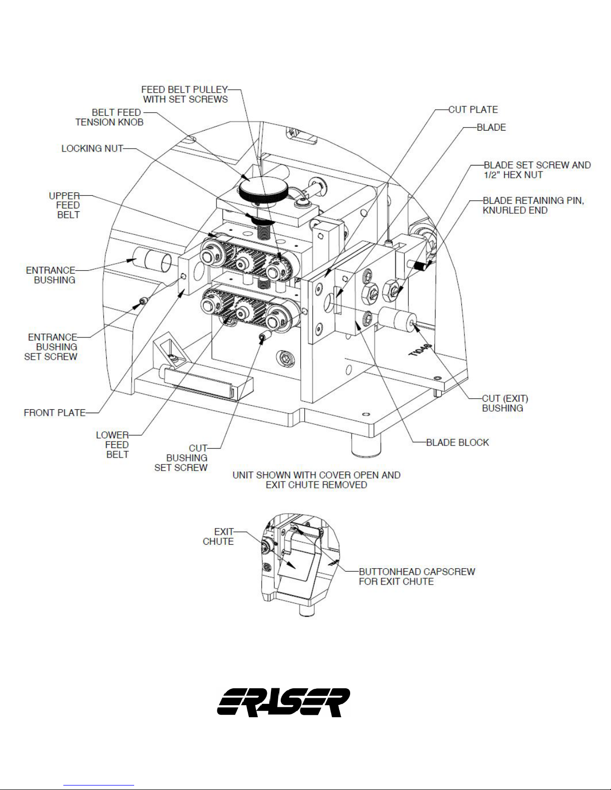
Refer to diagram on page 13. Open the front cover
and locate the front of the exit chute. Loosen the
button head cap screw holding the exit chute, and
slide the chute to the right to remove it. Loosen
the 1/2” hex nuts holding the blade screws in the
blade block, two places. Loosen the blade set
screws slightly with a screw driver. Remove the
blade retaining pin by pulling out on the knurled end.
Slide the blade forward through the blade block and
remove.
Slide the new blade in. It is necessary to adjust the
blade pressure by tightening the blade set screw
while sliding the blade back and forth until some
friction is felt. Then tighten the 1/2” hex nuts while
holding the blade set screw in place. If the blade is
too tight it will remain in the forward position. Loosen
again and readjust. Reinstall the blade retaining pin.
Reinstall the exit chute and close the front cover.
BUSHING CHANGE OR REPLACEMENT:
! CAUTION: Be sure unit is unplugged and
the air line is disconnected before changing
bushings.
Eraser Company Inc. • Syracuse, NY USA • Ph: 315-454-3237 • [email protected] • www.eraser.com • Fax 315-454-3090
Page 12

MODEL WC601A AUTOMATIC WIRE & TUBING CUTTER
p 12
Refer to diagram on page 13. To change the
entrance bushing, open the front cover. Loosen the
entrance bushing set screw in the front plate with the
5/64” Allen wrench provided, and slide the entrance
bushing out. Insert the desired entrance bushing
and tighten. Be sure the entrance bushing does not
come in contact with the feed belts.
To change the cut (exit) bushing, loosen the button
head cap screw holding the exit chute with the 3/32”
Allen wrench provided. Remove the exit chute by
sliding it to the right. Locate the set screw holding
the cut bushing. While holding the cut bushing,
insert the 3/32” Allen wrench into the cut plate, and
loosen the cut bushing set screw. Remove the cut
bushing by sliding it out of the cut plate. Note that
you can only remove the cut bushing through the
cut plate if the blade is removed, otherwise remove
it through the feed belt side. Slide the new cut
bushing into place and align the cut bushing with
the cut plate. The tapered (countersunk) end of the
bushing should face the belts. Using a straight edge,
at piece of metal, or the blade, align the cutting
(ground) edge of the cut bushing with the surface
of the cut plate. Tighten the cut bushing set screw.
Reinstall the exit chute assembly and close the front
cover.
IMPORTANT: THE NEW BUSHING MUST BE
PROPERLY ALIGNED WITH THE CUT PLATE
TO ENSURE SQUARENESS OF CUT AND
BLADE AND BUSHING LIFE. IF THE BUSHING
PROTRUDES PAST THE CUT PLATE, SEVERE
DAMAGE TO THE CUT BLADE WILL OCCUR.
FEED BELT REPLACEMENT:
! CAUTION: Be sure to unplug the unit and
disconnect the air supply before performing any
maintenance.
! CAUTION: Employ appropriate anti-static
procedures and devices when assembling or
disassembling the unit.
Refer to diagram on page 13. Loosen the set
screws on the pulleys. Remove the belts and pulleys
from their shafts. Slide the new belt onto the pulleys,
reinstall pulleys onto their shafts and tighten the set
screws.
GENERAL MAINTENANCE:
Check the cut bushing and blade for wear and
replace if dull. Due to the number of different
materials, the timing of checks will be determined
based on the material being run. Keep unit clean
and free of dust and debris. No lubrication or other
regular maintenance is required.
TROUBLESHOOTING
Problem Possible Cause Possible Solution
Blade stuck in the closed
position
Material doesn’t feed properly
Display not functioning
Poor quality of cut or no cut
Erratic cut lengths
Blade hitting the cut bushing
Belt feed not adjusted
correctly
Cut bushing too small
Blown fuse Replace with recommended fuse
Unit not powered up Turn power switch on, in the rear of the unit
Incorrect voltage supplied
Dull or chipped blades Dull or chipped blades must be replaced
Cut bushings not installed
correctly
Uneven Dereeler tension Make sure at high speeds, a power assisted dereeler is used
Feed belts not adjusted
correctly
Cut bushing too small
Re-Install cut bushing (See the cut bushing installation
procedure)
Tighten the belt feed adjusting knob clockwise to increase
tension (Do not over tighten, this will cause material to jam)
Re-Install cut bushing (See the cut bushing installation
procedure)
Make certain the incoming voltage is correct and is NOT being
inuenced by large equipment upstream.
Re-Install Cut bushings (See the Cut bushing installation
procedure)
Tighten the feed belt adjusting knob clockwise to increase
tension clockwise to increase tension
Re-Install cut bushing (See the cut bushing installation
procedure)
Eraser Company Inc. • Syracuse, NY USA • Ph: 315-454-3237 • [email protected] • www.eraser.com • Fax 315-454-3090
Page 13
MODEL WC601A AUTOMATIC WIRE & TUBING CUTTER
p 13
The Eraser Company, Inc.
PO Box 4961/ Oliva Drive
Syracuse, NY 13221, USA
Always Moving Forward
Phone: (315) 454-3237
Fax: (315) 454-3090
®
Website: www.eraser.com
E-mail: info@eraser.com
IR1555
REV 06/15
 Loading...