

Page 1
Always Moving Forward
Operating Manual
Please Read Before Operating Unit
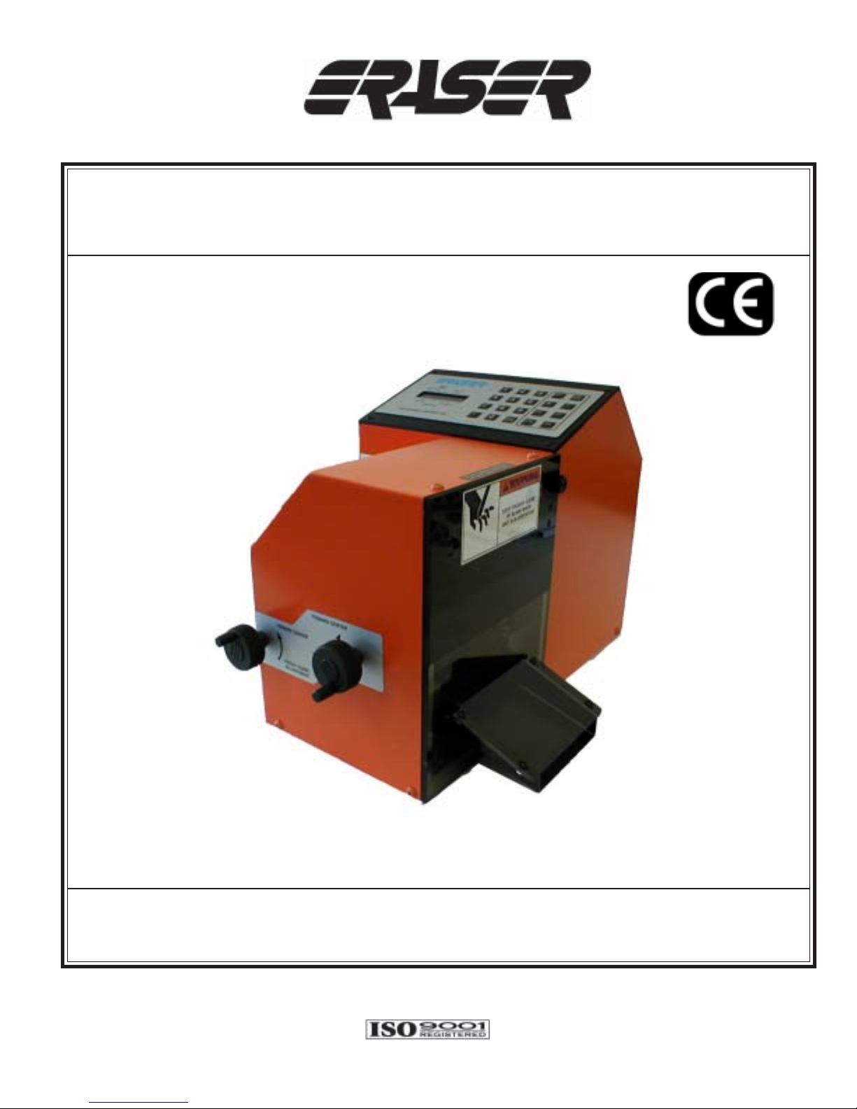
Model MMC100 Multi-Material Cutter
The Eraser Company, Inc.
PO Box 4961/ Oliva Drive
Syracuse, NY 13221, USA
Phone: (315) 454-3237 / Fax: (315) 454-3090
Website: www.eraser .com
E-mail: [email protected]
Service and All Spare Parts Available
Eraser International Ltd.
Unit M, Hunting Gate
Andover SP10 3SJ, England
Phone: (01264) 351347 / Fax: (01264) 355030
Website: www.eraser-international.com
Email: [email protected]
Page 2
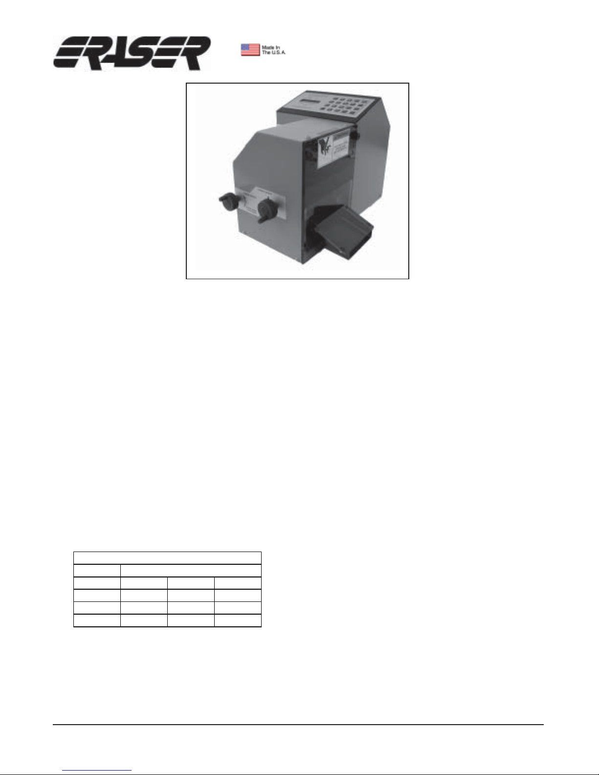
MODEL MMC100
MULTI-MATERIAL CUTTER
SPECIFICATIONS
Maximum Cut Length...........9,999,999.00 in./mm
Minimum Cut Length..................0.100” (2.54mm)
Maximum Material Size
Tubing........0.625” (5/8”) OD (15.875mmø)
Flat Material........3.94” (100.076mm) wide
Wire..........8 A WG (3.25mmø) solid copper
Tolerances........................................1% or better
dependent on material and feed
Feed Rates..................Three selectable feed rates
Feed Rate 1........9.5”/sec. (241.3mm/sec.)
Feed Rate 2......16.5”/sec. (419.1mm/sec.)
Feed Rate 3........31”/sec. (787.4mm/sec.)
Production Rates
Production Rates (PCs/hr.)
Feed Rate
Size 123
4" 4,045 5,900 7,200
10" 2,365 4,290 5,215
20" 1,395 3,000 3,530
ORDERING INFORMATION
AR0371 (MMC100)...Multi-material cutter 1 15V 60Hz
AR0372 (MMC100).................Multi-material cutter
European plug 220/240V 50Hz
AR0373 (MMC100).................Multi-material cutter
UK plug 220/240V 50Hz
AR3801 (DE400)................Optional vertical dereeler
AR0170 (DE700)....Optional compensation dereeler
IR1205......................Replacement guillotine blade
IR1203.............................Replacement anvil blade
Representative rates
Batching.............Up to 10 programmable batches.
Blades...........................Hardened and ground tool
steel guillotine and anvil blades.
Decibel Rating..........................................65 dB(A)
Eraser Company Inc. • Syracuse, NY USA • Ph: 315-454-3237 • [email protected] • www.eraser.com • Fax 315-454-3090
Eraser International Ltd. • England • Ph:(01264)351347 • [email protected] • www.eraser-international.com • Fax (01264)355030
Page 3

Model MMC MULTI-MATERIAL CUTTER
OPERATING INSTRUCTIONS
SET-UP
The MMC100 is supplied with one fixed stationary blade and one moveable blade. Also included
are three Allen wrenches; 1/8”, 3/16” & 9/64”.
Caution: The MMC100 comes with the blades
completely installed. These blades are intended
for use on wire and tubing and are extremely
sharp. Caution must be used when removing or
installing either of these blades.
Place the unit on a sturdy workbench with the right
side exit chute even with the right side of the
bench. Short and long cut lengths will drop out
the right side of the exit chute. Material collection
bins can be placed to collect the cut material as it
exits. If using the DE700 (or any other tensioning
de-reeler) place the de-reeler to the left of the unit
at least 24” from the entrance. Refer to the dereeler’s operating instructions for further set up
details.
Insert the power cord into the IEC connector. Plug
the unit into the appropriate power supply using
the correct plug for the unit purchased. Use a properly grounded mains supply. The American plug
is for use on 110/120V 60Hz mains supply. The
European and United Kingdom plugs are for 220/
240V 50Hz mains supply . Connect clean, dry, compressed air at 90 P.S.I..
Caution: Environmental conditions for proper operation should be 50° F-104° F (10° C-40° C) and
30-75% relative humidity . The MMC100 should be
operated in a well-ventilated open workspace. This
machine may be effected by outside environmental disturbances. The unit is rated for continuous
use and is protected by one fuse located in the
IEC connector.
Caution: Safety glasses or other suitable eye protection should be worn when operating this unit.
OPERATION
Place the material to be cut on the de-reeler. T urn
the MMC100 on using the I/O switch on the side
of the unit. Do not turn the unit on and off repeat-
edly without waiting 5 seconds for the controller to
remove information correctly . Removing the guard
during a run is not recommended. It will stop the
stepper motor and the piece being processed will
not be of the correct length. If cutting long pieces
of material and the guard is opened and closed
before the end of the cycle the stepper motor will
resume feeding material. This piece will not be the
correct length and should be discarded.
Open the belt feed by turning the switch counterclockwise to disengage the belt feed. Rotate the
knobs on the front of the unit to open the guides
wide enough to accommodate the material being
cut. Feed the material through the guides until it
protrudes past the blades on the right side of the
unit. Make certain the material is between the two
sets of guides located on the left and right side of
the belt feed.
Turn the switch clockwise to close the belt feed
and engage the upper belt. Make certain the unit
is at the beginning of the batch. Press the cut
button twice to zero the machine. NOTE: The guillotine blade will cut the material off at the blade.
When using the JOG or CUT keys this will place
the operator in the manual mode. In the manual
mode “MANUALC” will be displayed in the STATUS area. This is a continuous jog function and
the length displayed is the actual length of material moved. Pressing the CUT key will cut off the
length of material just transported. Press the ESC/
PAUSE key to return to the batch screen. If the
material does not feed it can be inserted manually
with the belt feed open.
The MMC100 is equipped with an out of material
sensor. From the factory this option is disabled. T o
enable this option, use the following procedure.
From the “SELECT BATCH” screen, hit the edit
key twice. The display will read “WIRE SENSOR
1=Y 0=N”. Select 1 if you would like to use the sensor and 0 if you would like to disable the sensor.
After selecting your option, press the <ENTER> or
<ESCAPE> key to return you to the “SELECT
BATCH” screen. The unit is now ready for programming.
Page 4

PROGRAMMING
When the unit is turned on the controller will report
that it is initializing and display The Eraser Co.
MMC100. The controller will request that you select a batch. Select a batch from 1-10. Numbers
other than 1-10 will not be accepted. Inputs that
are not recognized will emit a beep. Press ENTER
or RUN to continue. The functions in figure 1 will
be displayed on the keypad display .
BA TCH Units LENGTH
IN/MM
• • • • ••••••••••
run. At the end of the run “END” will be displayed.
Pressing RUN will put the operator back at the
BATCH screen and pressing RUN will start the
same batch again or the operator may change the
batch at this time.
POWER FAILURE
In case of power failure the MMC100 will be
reinitialized and should not start unexpectedly. All
parameters stored in a batch program will remain
in memory . A fuse and a line filter located in the IEC
connector protect the controller.
BLADE REPLACEMENT
•••••• • •••••••
STATUS FEED RATE QUANTITY
Figure 1
To begin the run cycle press RUN again only if all
the information has been previously inputted for
the batch. If a variable is entered with a value of 0
an error will cause the controller to beep. Press
ENTER after each inputted value. This will highlight the next variable to be inputted. After pressing ENTER IN/MM will be blinking on the display.
Pressing the + or – keys will change the display
from IN to MM or MM to IN. Press ENTER and
input the length needed. This has a total of 10
characters, one of which is reserved for a decimal and two for zeroes (9999999.00”). After pressing ENTER select a feed rate of 1-3. One is the
slowest at 9.5”/sec and 3 is the fastest at 31”/sec.
It is advised to start with the lowest feed rate, check
the results and then adjust as necessary . The next
variable to be entered is QUANTITY. The maximum allowed is 9999999 pieces. Enter the quantity and press ENTER or RUN. Pressing ENTER
will display “READY” in the status and pressing
run will start the run cycle immediately. Pressing
ENTER will cycle the operator through the variables. During the run cycle the quantity will count
down until 0 is reached. After reaching 0 “END”
will be displayed. If it is necessary to pause the
unit during a run press ESC/PAUSE. After pressing the P AUSE key “PAUSE” will be displayed. The
amount of material transported before pausing will
be displayed under LENGTH. Pressing ESC again
will abort the program. Pressing RUN will display
“READY” and pressing RUN again will continue the
Caution: Always remove compressed air supply and unplug electrical supply when replacing blades or servicing the unit.
Note: Whenever a blade or both blades are replaced
follow the adjustment procedure.
1. Remove guard and chute assembly by removing the four thumbscrews.
2. Manually raise the moveable blade to its upper
most position, if it is not currently there, by forcing
the upper blade holders up.
3. Using the 9/64” Allen wrench provided, remove
the fixed lower blade by removing the three cap
screws securing it to the lower blade holder.
4. Remove the cap screw securing the upper
moveable blade to the right upper blade holder using the 3/16” Allen wrench provided. Rotate the
upper blade holder block out to reveal the threaded
hole in the blade (if the blade holder block does not
rotate easily, try sliding it up and down while rotating). Insert the screw that was just removed into
the threaded hole about 3 full turns. Use this screw
to support the blade while removing the screw from
the left upper blade holder (see S pecification Photo
1). Rotate the left upper blade holder out and insert
the removed screw back into the threaded hole.
Caution: the blade is now free and may fall if
not supported. Use the screws in the blade as
handles to safely remove the blade (see Specification Photo 2). Move the blade back until it disengages from the knuckle key . Then move the blade
down and out of the machine.
Page 5
5. Replace the lower blade by securing it with the
three fasteners using the 9/64” Allen wrench provided.
6. Replace the upper blade by inserting the cap
screws into the threaded holes and using them as
handles to raise the blade up into the machine so
that it engages the knuckle key. Remove the left
screw and swing the blade holder over the blade
and insert the screw into the holder. Snug the screw
with the 3/16” Allen wrench. DO NOT TIGHTEN.
Remove the screw from the right side of the blade
and swing the right blade holder over the blade.
Insert the screw into the hole and tighten with the
3/16” Allen wrench provided. Tighten the left side
blade holder. Make sure upper blade is centered
with the lower blade.
7. Whenever a blade or both blades are replaced
follow the adjustment procedure.
BLADE ADJUSTMENT
6. Raise the upper blade and slowly lower it back
down. There should be a smooth shearing action
like a pair of scissors. If not, repeat steps 3 thru 5
again until you achieve a smooth shearing action.
7. Tip the machine onto its backside and tighten
the two screws securing the lower blade holder
with the 3/16” Allen wrench.
8. Return the machine to an upright position and
recheck the shearing action of the blades.
9. Return the machine to service by installing the
safety guard, air supply and power.
1. Tip the machine onto its backside and loosen
the two large screws on the bottom of the machine with the 3/16” Allen wrench (see Specification Photo 4).
2. Tip the machine back onto its feet and loosen
the two tension screws in the bottom of the lower
blade holder with the 3/16” Allen wrench. Push the
lower blade holder towards the center of the machine.
3. Lower the upper blade so that only the leading
edge of the upper blade covers the lower blade.
Caution: ensure the upper blade does not hit
the top of the lower blade as this will damage
the upper blade.
4. Tighten the tension screw in the lower blade
holder so the lower blade comes in contact with
the upper blade. Raise the upper blade and slowly
lower it down again to ensure the upper blade does
not come down on top of the lower blade.
5. Lower the upper blade all the way down and
tighten the left tension screw on the lower blade
holder until the lower blade is snug against the upper blade.
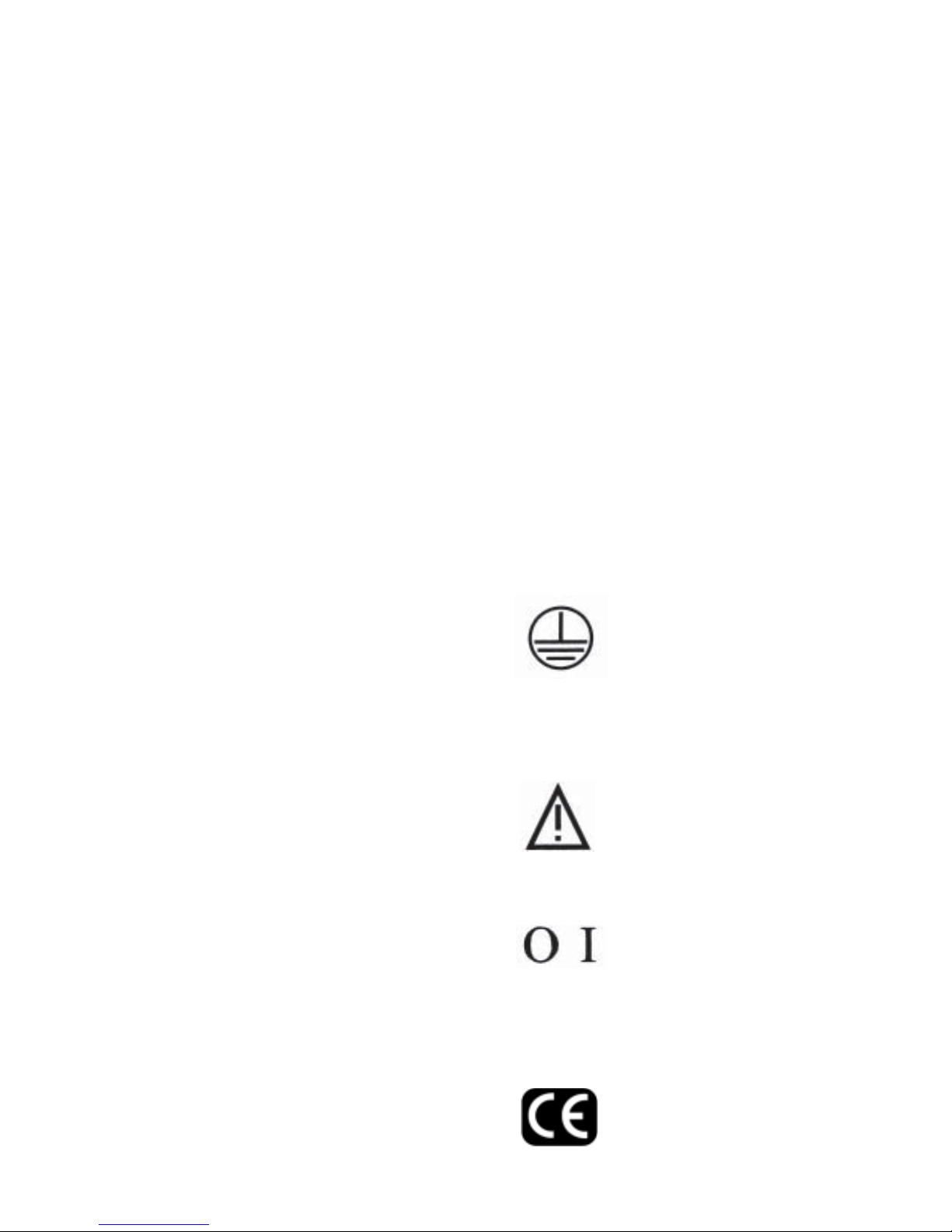
GROUND LOCA TION
This protective Earth ground label is located inside the housing beside the ground wire. This
wire is connected to the Power
Supply Cable and is wired back
through the Mains supply to
ground.
CAUTION LABEL
Refer to the operating instructions before using this unit. High
voltage is inside this unit and
power must be disconnected
before servicing.
ON/OFF LABEL
This is the ON/OFF switch.
Press I for on and press O for
off. This switch is also the antistart switch. In case of power
outage, this switch must be reset
for the unit to operate.
CE MARKING
Indicates compliance with all applicable EU directives.
Page 6

IMPORTANT SAFETY INSTRUCTIONS
READ ALL INSTRUCTIONS
WARNING
DO NOT OPERATE TOOL UNTIL YOU HAVE READ
THOROUGHL Y , AND UNDERSTAND COMPLETEL Y ,
ALL INSTRUCTIONS, RULES, ETC. ON THIS P AGE,
AND IN THE OPERATING MANUAL. WHEN USING
ELECTRIC TOOLS, BASIC SAFETY PRECAUTIONS
SHOULD AL WA YS BE FOLLOWED T O REDUCE RISK
OF FIRE, ELECTRIC SHOCK, AND PERSONAL INJURY , INCLUDING THE FOLLOWING:
GROUNDING INSTRUCTIONS
In the event of a malfunction or breakdown, grounding
provides a path of least resistance for electric current to
reduce the risk of electric shock. This tool is equipped
with an electric cord having an equipment-grounding conductor and a grounding plug. The plug must be plugged
into a matching outlet that is properly installed and
grounded in accordance with all local codes and ordinances.
ing, gloves, neckties, rings, bracelets, or other jewelry
that might get caught in moving parts. Nonslip footwear
is recommended. Wear protective hair covering to contain long hair .
DON’T OVERREACH. Keep proper footing and balance
at all times.
MAINT AIN TOOLS WITH CARE. Keep tools sharp and
clean for best performance and to reduce the risk of injury. Follow instructions for lubricating and changing
accessories.
DISCONNECT TOOL before servicing; when changing
accessories, such as blades, wheels, cutters, and like.
USE RECOMMENDED ACCESSORIES. Consult the operating manual for recommended accessories. The use
of improper accessories may cause risk of injury to persons.
Do not modify the plug provided – if it will not fit the outlet, have the proper outlet installed by a qualified electrician.
Improper connection of the equipment-grounding conductor can result in a risk of electric shock. The green conductor with or without yellow stripes is the equipmentgrounding conductor. If repair or replacement of the electric cord or plug is necessary , do not connect the equipment-grounding conductor to a live terminal.
Check with a qualified electrician or service personnel if
the grounding instructions are not completely understood,
or if in doubt as to whether the tool is properly grounded.
Use only 3-wire extension cords that have 3-prong grounding plugs and 3-pole receptacles that accept the tool’s
plug. Repair or replace damaged or worn cord immediately.
GENERAL INSTRUCTIONS
REMOVE ADJUSTING KEYS AND WRENCHES. Form
habit of checking to see that keys and adjusting wrenches
are removed from tool before turning on.
KEEP WORK AREA CLEAN. Cluttered areas and
benches invite accidents.
DON’T USE IN DANGEROUS ENVIRONMENTS. Don’t
use power tools in damp or wet locations, or expose
them to rain. Keep work area well lighted.
ALWAYS USE SAFETY GLASSES. Everyday eyeglasses only have impact resistant lenses; they are NOT
safety glasses. Also use face or dust mask if cutting
operation is dusty .
WEAR PROPER APPAREL. Do not wear loose cloth-
CHECK DAMAGED P ARTS. Before further use of the
tool, a guard or other part that is damaged should be
carefully checked to determine that it will operate properly and perform its intended function. Check for alignment of moving parts, binding of moving parts, breakage
of parts, mounting, and any other conditions that may
affect its operation. A guard or other p art that is damaged
should be properly repaired or replaced.
DO NOT EXCEED THE MAXIMUM MA TERIAL SPECIFICATIONS.
DO NOT OPERATED UNIT WITHOUT GUARDS IN
PLACE OR GUARDS NOT IN WORKING ORDER.
DO NOT PERFORM MAINTENANCE OR ADJUSTMENTS WITH POWER ON.
DO NOT PLACE FINGERS OR APPENDAGES IN OR
NEAR OPENINGS IN GUARDS.
DO NOT RUN UNIT WITH INCORRECT LINE VOLTAGE. REFER TO LABEL PLACED OVER I/O SWITCH.
DO NOT ALLOW UNTRAINED OR UNQUALIFIED PERSONNEL TO OPERA TE UNIT .
DO NOT DEFEA T ANY OF THE SAFETY FEA TURES
DESIGNED INTO THE UNIT.
IMPORTANT: No liability will be incurred by The
Eraser Co. for injury, death, or property damage
caused by a product which has been set up, operated, and/or installed contrary to Eraser's written
instruction manual, or which as been subjected to
misuse, negligence, or accident, or which has been
repaired or altered by anyone other than Eraser, or
which has been used in a manner or for a purpose
for which the product was not designed.
Page 7
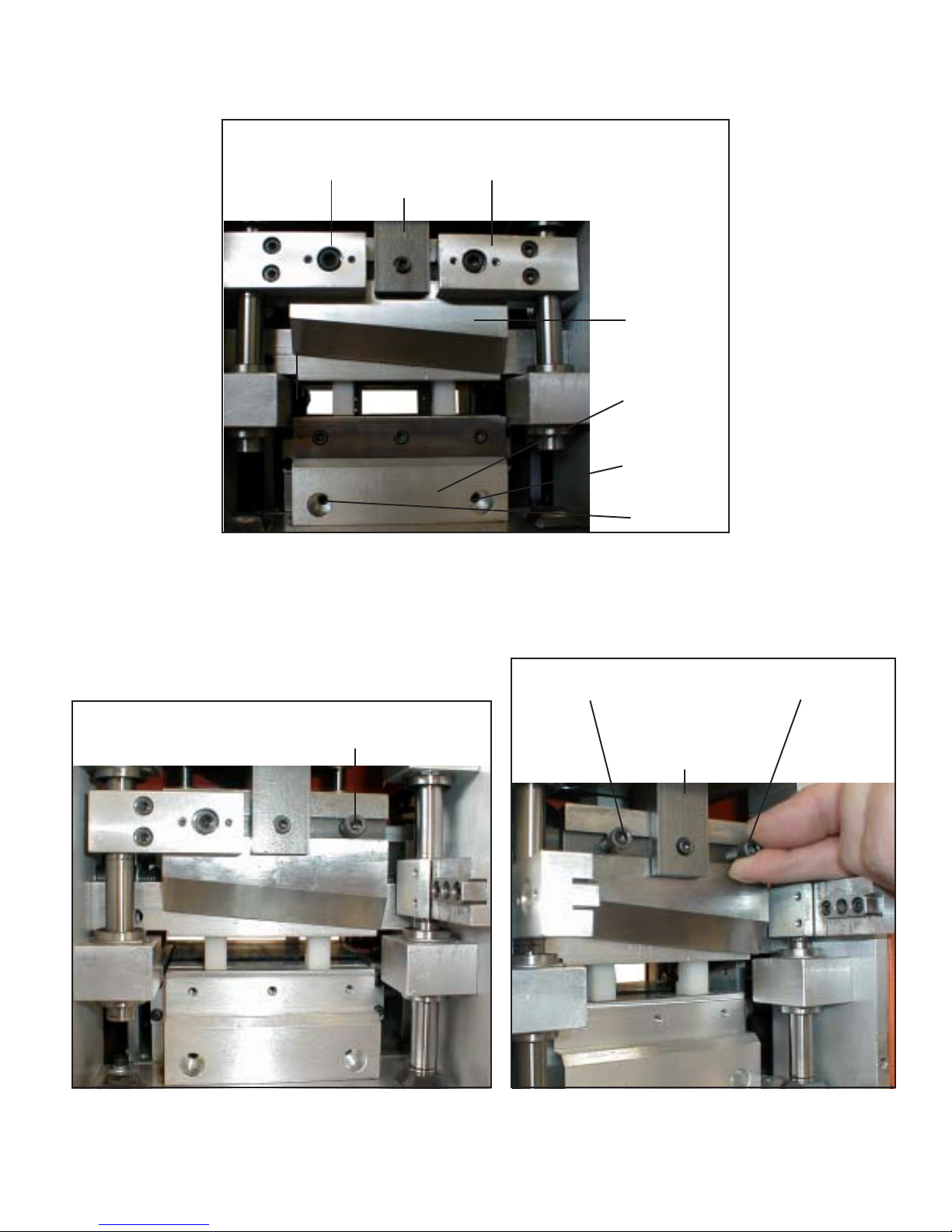
SPECIFICATIONS
Left Blade
Holder
Knuckle with Key
Right Blade
Holder
Upper
Blade
Lower Blade
Holder
Right Tension
Screw
Left Tension
Screw
Specification Photo 1
Replace screw to use as a
handle (repeat for left side)
Specification Photo 2
Firmly grasp both cap screws and push blade
off of the knuckle key, lower blade and
remove from machine.
Knuckle with Key
Specification Photo 3
Page 8
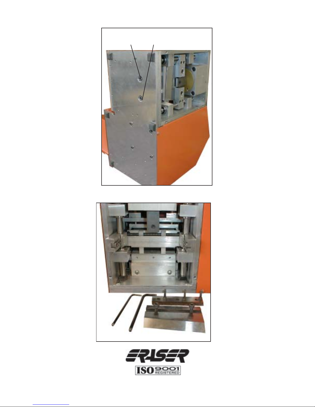
Lower Blade
Holder Screws
Specification Photo 4
The Eraser Company , Inc.
PO Box 4961/ Oliva Drive
Syracuse, NY 13221, USA
Phone: (315) 454-3237 / Fax: (315) 454-3090
Website: www.eraser.com
E-mail: [email protected]
Eraser International Ltd.
Unit M, Hunting Gate
Andover SP10 3SJ, England
Phone: (01264) 351347 / Fax: (01264) 355030
Website: www.eraser-international.com
Email: [email protected]
IR1266
REV9/03
 Loading...