

Page 1

INSTALLATION AND
OPERATING MANUAL
Version 1.0
VALIANT
Solar Siren Alarm Kit
Page 2

DoP N
o
: EM0017
ERA - VALIANT-Red Lens
Page 3

IMPORTANT
PLEASE READ THIS MANUAL CAREFULLY BEFORE OPERATING
THE SYSTEM AND RETAIN FOR FUTURE REFERENCE.
All devices, with the exception of the external siren are suitable for mounting
in dry interior locations only.
Any repairs must be carried out by an Authorised Repair Centre. Misuse
or attempted repairs to a component part of the product will invalidate the
warranty. The photocopying, copying, reproduction, translation to any language,
modification, storage in a retrieval system or retransmission, in whole or in part,
in any form or by any means, electronic, mechanical or otherwise of this manual,
is strictly prohibited without the prior written permission of ERA Home Security.
Disposal and Recycling
Disposal of this product is covered by the Waste Electrical or Electronic Equipment
(WEEE) Directive. It should not be disposed of with other household or commercial
waste.
At the end of the product’s useful life, the packaging and product should be disposed
of via a suitable recycling centre. Please contact your local authority or the retailer
from where the product was purchased for information on available facilities.
Declaration of Performance
This equipment complies with the essential requirements of the Radio and
Telecommunications Terminal Equipment Directive, 1999/5/EC.
Additional Accessories
This can easily be extended at any time with the range of ERA Wireless Alarm
Accessories for details visit www.erahomesecurity.com or call our Customer
Support team on 0345 257 2500 (local call rate).
Page 1
Page 4

TABLE OF CONTENT
Kit Contents
1. PIR Motion Detector
1.1 Get to know your product
1.2 LED Indication
1.3 PCB Layout
1.4 Test Mode
1.5 Working Mode
1.6 Installation
2. Magnetic Door/Window Sensor
2.1 Get to know your product
2.2 PCB Layout
2.3 Installation
3. Remote Control
3.1 Get to know your product
3.2 Buttons/Functions
4. Solar Charged Siren
4.1 Positioning
4.2 PCB Layout
4.3 Jumper Setup
4.4 Usage
4.5 Installation
4.6 Jamming Detection
5. Specification
3
3
3
3
4
4
4
4
5
5
6
6
7
7
7
8
8
8
8
9
10
10
11
6. Notes 12
ERA Product Guarantee 13
Specifications
Page 2
Page 5
KIT CONTENTS
Wireless Solar Siren x 1
Door/Window Sensor x 1
PIR Motion Sensor x 1
Remote Control x 1
Batteries Included
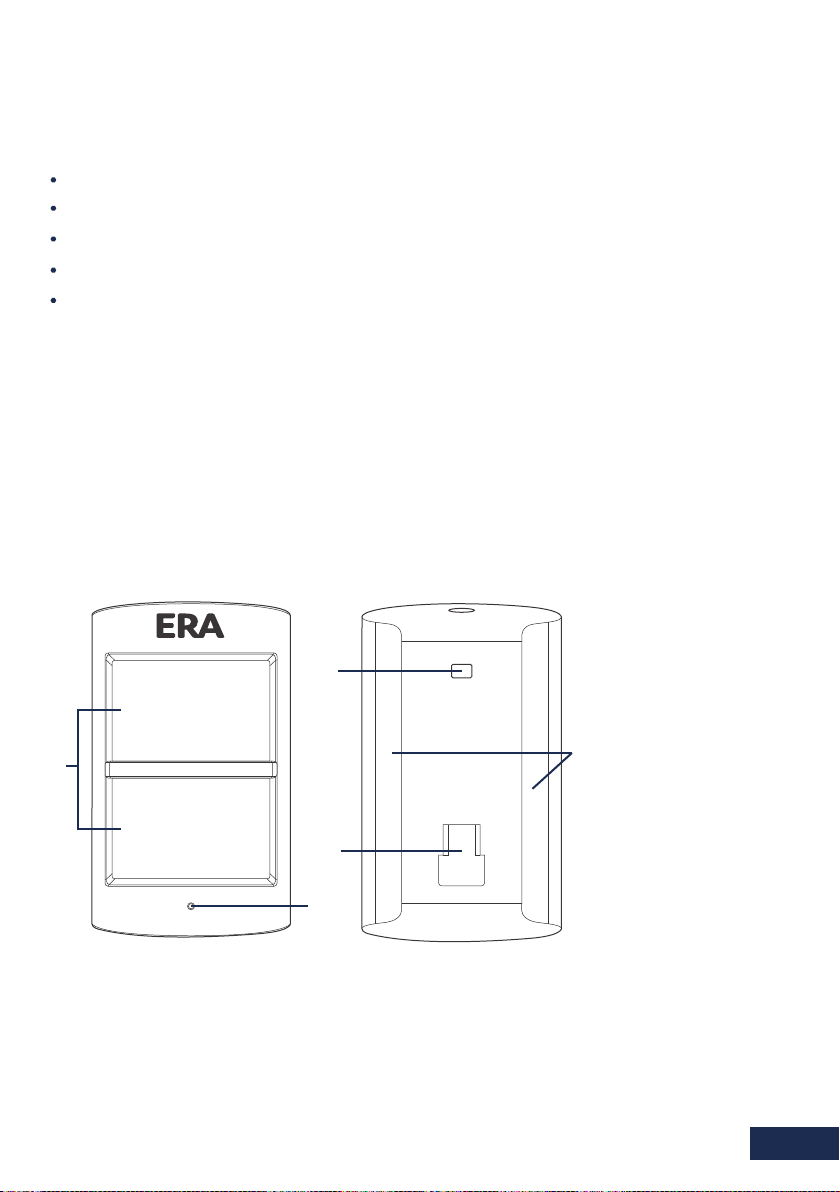
1. PIR MOTION
DETECTOR
1.1. Get to know your product
3
1
4
2
1.2. LED Indication
Flashes every 2 seconds: Self-testing state
Flashing twice: Self testing finished, enters working mode
Flashes once: Movement is detected
Flashes once every 3 seconds: Low battery indication (immediate battery change required).
1. Detection Window
2. Status Indicator
3. Test Button
5
4. Bracket Slot
5. Self-adhesive pad
fixing markers
Page 3
Page 6

1.3. PCB Layout
Tamper
Switch
Status
Indicator
Infrared
Sensor
Zone
Setting
AA 1.5V LR6
AA 1.5V LR6
1.4. Test Mode
Remove the activation strip. Fit the retaining
1.
screw supplied.
Self-testing will commence for 1 minute as
2.
indicated by the LED flashing every 2 seconds.
Infrared Sensor: Detects movement and
triggers an alarm signal when the system
is armed.
Tamper Switch: If the casing is opened
when in ‘working state’, the tamper
switch will be triggered and generate an
alarm signal.
Test
Button
3.
To enter Test Mode press the test button at the
back of the PIR. The LEDs will then flash once
when movement is detected, for up to 3 minutes.
1.5. Working Mode
To test in Working Mode, walk in front of the sensor, the LED should flash once when
1.
movement is detected.
If the sensor is triggered twice in 3 minutes it will enter into power saving (sleep mode).
2.
If no movement is detected within the next 3 minutes, the sensor will return to normal
working mode.
1.6. Installation
Avoid mounting the sensor in areas where draughts may be present or where the
1.
temperature may fluctuate greatly, such as near to windows, air conditioning, heating,
refrigeration units, cooking appliances and direct sunlight.
Page 4
Page 7

2.
Where possible, mount the sensor in the corner of the room so that the logical path
of an intruder would cut across the fan detection pattern. A PIR responds more
effectively to movement across the device that to movement directly towards it.
Fit the sensor in a position that will cover your desired protection area:
a.
Fix the bracket to the wall with the fixings kit supplied. For optimum
performance set the height of the bracket to 2 metres above ground
level.
b.
Adjust angle of the PIR sensor to cover the required detection area.
To perform a walk test.
Press the test button
once and walk from let
2m
to right in the room.
The LED indicator will
flash once when motion
is detected.
2. MAGNETIC DOOR/
WINDOW SENSOR
2.1. Get to know your product
Status Indicator
Transmitter
Magnet
Suitable for fitting to doors,
windows and any object that
opens and closes.
The Window/door sensor transmits
a signal to the control panel/siren
when ‘contact’ is broken between
the transmitter and the magnet.
Transmits a low battery signal to
the ERA alarm control panel.
Page 5
Page 8

2.2. LED Indication PCB Layout
Flashes once: Door/window opened,
transmitter sends the signal to the
control panel/ siren.
Flashes every 3 seconds: Low battery
indication (immediate battery change
recommended)
Battery
Tamper Switch
Zone Setting
2.3. Installation
Carefully remove the activation strip
1.
from the battery compartment.
2.
Remove the backing paper from one side
of each self-adhesive double-sided strip.
Fix one strip to the back of the magnet
and one to the back of the transmitter.
3.
Peel off the other side of each adhesive
strip. Mount the magnet on the door and
the transmitter on the door frame, with
less than a 1cm separation between the
two.
4.
When opening the door a small red indicator
lights up briefly, this indicates that the
transmitter has sent a signal to the control
panel.
Note: Please refer to the full system instructions for pairing a magnetic sensor.
Do not use the button on the back of the sensor to pair the sensor to the alarm as this
will put the sensor into 24hour mode.
Page 6
Page 9

3. REMOTE
CONTROL
3.1. Get to know your product
The remote control enables you to quickly and
Arm
Disarm
conveniently arm and disarm your alarm system.
Part Arm
(Home Arm)
3.2. Buttons/Functions
Arm
Disarm
Part Arm
(Home Arm)
Panic Alarm
Mute Arm
Mute Disarm
SOS Panic
In the event of an emergency (when in or near
your property), pressing the SOS button will
trigger the an alarm on the control panel/siren.
LED Indication
Flashes Once: Transmits the signal
Low Light Level: Low battery
indication, change the battery.
Press to arm the control panel/siren and all of the accessories
(Full Arm)
Press to disarm the system
Press to part arm the alarm system (for systems with control
panels only)
Press to activate the panic alarm (SOS).
Press to arm the system with the solar siren in muted/silent
mode.
Press to disarm the system with the solar siren in mute/silent
mode.
Note:
1. For Mute Arm & Mute Disarm operation; press the home button for 1-2 seconds, then press the
Arm or Disarm button for a further 1-2 seconds.
2. The Mute Arm/Disarm will only be performed once before returning to sound. So the Mute
Arm/Disarm process would have to be done each time it is required.
3. By default arm/disarm is with sound.
Page 7
Page 10

4. SOLAR CHARGED
Mute
Low
High
Low
2Min
30s
5Min
30s
High
Mute
5Min
2Min
SIREN
4.1. Positioning
Install the Siren to the outside of the building in a position that is clearly visible and at a
height which is relatively inaccessible to an intruder.
The Siren is designed to work on any aspect wall, however for optimum performance try
to avoid installing on a north facing wall or to a wall with shadows cast by other buildings,
trees and roof overhangs.
For optimum radio signal reception mount the Solar Siren to Maximum distance of one
metre from any external or internal metalwork (drainpipes, gutters, radiators, etc).
4.2. PCB Layout
Siren Duration Setting
Volume Setting Power On/Off
9V
Rechargeable 3.7V
1800mAh Lithium Battery
Start-up
Battery
Rear Cover
Tamper Socket
Inner Tamper Switch
Learn Button
Rear
Anti-tamper
Switch
Sirens
4.3. Jumper Setup
Volume
Setting
Siren Duration
Setting
Page 8
High
5Min
Status LED Indicator
Alarm LED Indicators
(Default)
Mute
2Min
Low
(Default)
30s
Page 11

4.4. Usage
Please connect the 9V battery and press the power on/off button prior.
Please note: after charging the battery for 12-24 hours, please remove the 9V battery.
When installed as part of an ERA Alarm System, the Siren must be registered to the
control panel only.
Connecting to a Control Panel
Press the Learn button on the Solar Siren (0.5 seconds), the system goes into Learn
1.
Mode after one beep is heard.
Press the Arm Button on the Control Panel app.
2.
The Wireless Accessory is learned successfully after a second beep. If two beeps are
3.
heard, the accessory is already linked.
To finish learning the siren, press the Learn button on the siren again to exit
4.
Learn Mode after one beep.
5.
The Control Panel is now Armed, press Unlock to Disarm the Control Panel.
The Siren arms 15 seconds after the Control Panel - please consider this when testing
the Siren. The Siren will sound and the strobe lights will flash upon alarm activation.
Disarming the system will stop the siren sounding. If not disarmed the Siren Status
Indicator will flash once every 2 seconds for one hour (visual notification of an alarm
event).
When installed as a Siren only Alarm System (without a Control Panel), all of the Alarm
Accessories must be registered to the Siren.
Connecting a Wireless Accessory to the Siren
Press the Learn Button on the Solar Siren (0.5 seconds), the system goes into Learn
1.
Mode after one beep is heard.
2.
Press the Test Button on the Accessory or trigger the Accessory once.
3.
The Wireless Accessory is learned successfully after a second beep. If two beeps are
heard, the accessory is already linked.
4.
To finish learning the Accessories, press the Learn Button on the Siren again to exit
Learn Mode after one beep. The ‘Arm’ button will arm the siren with a 15 second exit
delay. Sensors on the ‘single delay’ will have an entry delay of 15 seconds before the
alarm sounds (unless disarmed by the Remote Control during the delay period).
Sensors on the ‘normal zone’ will activate the alarm without a delay, i.e. the Siren
will sound immediately. The Siren will sound and the strobe light will flash upon
activation of a connected Accessory. Disarm the system to stop the siren sounding.
If not disarmed the Siren status indicator will flash once every 2 seconds for one hour
(visual notification of an alarm event).
Page 9
Page 12

4.5. Installation
1
Remove the fixing screw from
the bottom edge of the Siren
housing and carefully remove
the front cover.
2
Hold the mounting plate in
position and mark the positions
of the four mounting holes.
There is a Spirit Level inside
the case to help ensure that
the Siren is level.
3
Drill four holes in the wall and
insert the wall plugs. Insert the
screws through the backplate
holes and screw them into the
wall plugs.
4
Hinge the front cover locating tabs
over the top edge of the backplate
and carefully push the base of the
siren cover into place. Secure the
siren cover in place by refitting the
fixing screw in the bottom edge of
the cover.
Test Mode
Test Mode prevents the Siren’s tamper switch from triggering an alarm during
1.
maintenance or when changing the battery.
When the Remote Control is connected with the Siren, press [ ] 3 times (within 5
2.
seconds) to enter Test Mode, the Siren will emit a long beep indicating that the system
is now in Test Mode. During this period the Siren will not alarm but will beep if the
tamper switch or the connected sensors are triggered.
Press [ ] on the Remote Control to exit Test Mode after a short beep.
3.
The System is now Armed. Press Unlock to Disarm the System.
4.
Please note: pressing the rear anti-tamper switch 7 times will also enter test mode.
Enter/Exit Learning Status using a connected Remote Control
If the Siren has been fitted as a standalone system, additional accessories can easily be
1.
learnt to the Siren without the need to dismount the Siren from the wall, as follows:
1
Press [ ] on the Remote Control 3 times (within 5 seconds) to enter Test Mode.
2.
Press [ ] 3 times (within 5 seconds) to enter Learn Mode. A long beep is heard from
3.
the Siren indicating that it is in Learn Mode.
Press the Test Button on the additional Accessory or trigger the Accessory once.
The Siren will beep again to indicate that the Accessory has been successfully connected
4.
with the Siren.
Press [ ] on the Remote Control to exit Learn Mode, it will emit one beep.
5.
6.
The System is now Armed, press Unlock to Disarm the System.
4.6. Jamming Detection
Jamming Detection will activate if the Siren receives a constant signal for 30 seconds or
3 lots of 10 seconds within a 5 minute period. If detected, the Siren will emit 10 seconds
of short beeps, if the signal is still detected, a full Alarm condition will occur.
We recommend that you wait up to 30 days before activating the Jamming Detection
feature to allow time for you to become familiar with the operation of your Alarm System.
Note: Jamming Detection is disabled by system default.
Page 10
Page 13

Enable Jamming
1.
Ensure the red power button is off
Hold down the tamper switch and then press the red power button, you
2.
will hear 1 beep to indicate Jamming Detection has been enabled.
Before letting go of the tamper switch, press the red power
3.
button again to prevent the Siren from sounding.
Disable Jamming
Ensure the red power button is off
1.
2.
Hold down the tamper switch and then press the red power button, you will hear 2
beeps to indicate Jamming Detection has been disabled.
Before letting go of the tamper switch, press the red power button again to prevent
3.
the Siren from sounding.
5. SPECIFICATION
Solar Siren
Model No.
Back Up Power
Start Up Power
Solar Panel Output Current
Standby Current
Maximum Alarm Current
Standby Time
Maximum Siren Volume
Receiving Distance
Radio Frequency
Housing Material
Operation Conditions
Dimensions (L x W x H)
Pet Friendly PIR Sensor
Model No.
Power Supply
Standby Current
Alarm Current
Detection Scope
Transmitting Distance
Pet Immunity
Radio Frequency
Housing Material
Operating Condition
Dimensions (L x W x H)
Detector - 100mm x 59mm x 43mm
Transmitter - 52mm x 30mm x 26.5mm
3.7V 1800 mAh Rechargeable
ERA-VALIANT-R
Lithium Battery
9V Alkaline Battery
2000LUX illumination >4mA
(in sunlight)
≤1mA
≤700mA
45 days (in case of no sunlight)
110dB
≤80m (in open area)
433MHz
PC + ABS Plastic + ANTI-UV
Temperature: -20°C - +55°C
Humidity: ≤90% (non-condensing)
309mm x 230mm x 79.7mm
EPIR
DC3V (AA LR6 Batteries x 2pcs)
≤50uA
≤9.5mA
≤8m/110°
≤80m (in open area)
≤25kg
433MHz
ABS Plastic
Temperature: -10°C - 55°C
Humidity: ≤80% (non-condensing)
Door/Window Sensor
Model No.
Power Supply
Static Current
Alarm Current
Transmitting Distance
Radio Frequency
Housing Material
Operation Condition
Dimensions (L x W x H)
Transmitter: 71mm x 31.5mm x 15mm
Remote Control
Model No.
Power Supply
Alarm Current
Transmitting Distance
Radio Frequency
Housing Material
Operating Condition
Dimensions (L x W x H)
DC3V (CR2025 Lithium Battery x 1pc)
DC 3V (CR2032 Lithium x 2pcs)
EMAG
≤5uA
≤9mA
≤80m (in open area)
433MHz
ABS Plastic
Temperature: -10°C - 55°C
Humidity: ≤80% (non-condensing)
Magnet: 71mm x 12.5mm x 15mm
ERA-REMOTE
≤7mA
≤80m (in open area)
433MHz
ABS Plastic
Temperature: -10°C - 55°C
Humidity: ≤80% (non-condensing)
53mm x 31mm x 9.5mm
Page 11
Page 14

6. NOTES
Disposal and Recycling
Disposal of this product is covered by the Waste Electrical or Electronic Equipment (WEEE)
Directive. It should not be disposed of with other household or commercial waste.
At the end of its useful life the packaging and product should be disposed of via
a suitable recycling centre. Please contact your local authority or the retailer
from where the product was purchased for information on available facilities.
Page 12
Page 15

ERA PRODUCT GUARANTEE
We at ERA firmly believe in the quality of our goods. Our technology achieves outstanding performance and
durability and we can therefore offer, in addition to your statutory rights, an additional limited guarantee.
In the event of any material defects in any product manufactured by us due to faulty design, materials and/or
workmanship, and which arise following correct installation and during normal use in accordance with our
instructions, as included in the product packaging, within the period of two years from the date of purchase,
we will either repair, provide a replacement, substitute with an equivalent product free of charge from our then
current range or refund in full the amount paid for the product at point of purchase.
Conditions
In order to take advantage of our guarantee, you must comply with the following conditions:-
1. This limited guarantee is not transferable and is extended only to, and is solely or the benefit
of, the original purchaser of the product. Please retain your dated sales invoice as proof of
purchase and forward this to us if you wish to make a claim under this guarantee.
2. Products must be installed, used and maintained in accordance with our instructions otherwise
the guarantee will be invalidated.
3. The product must not be damaged or modified in any way nor must it have been subjected to
any unauthorised repairs.
Exclusions
This guarantee does not cover:-
1. Periodic maintenance, repair and replacement of parts due to fair wear and tear.
2. Abuse or misuse, including but not solely limited to the failure to use this
product for its normal purposes or in accordance with ERA’s instructions on usage and
maintenance.
3. Failure of the product arising from incorrect installation or use not consistent with the
instructions supplied and the cost of any removal or installation of products.
4. Accidents, Acts of God, lightning, water, fire, public disturbances, improper ventilation, voltage
fluctuations or any cause beyond the control of ERA (Force Majeure).
5. Unauthorised modifications carried out to the product.
6. Damage caused by incorrect/improper use of supplied batteries.
7. Alteration to, deletion, removal or illegibility of the Serial Number as shown on the Product
Label.
8. Consumables: any damages so caused by the use of batteries not supplied by ERA.
9. Repair or attempted repairing by bodies who are not ERA authorised repairers.
10. Neglect.
11. The loss of any stored data on your product.
This guarantee is in addition to your contractual and statutory rights and does not affect your statutory rights.
To make a claim
Please contact Customer Support either by telephone on 0345 257 2500 or email support@erahomesecuritycom,
with full details of your claim. If your claim satisfies our Conditions and is not subject to any of our Exclusions,
we will agree with you the repair, replacement, substitution or refund of payment of goods. For product returns
you will be issued with a Return Authorisation Number (RAN). Please note: Returns will not be accepted unless
accompanied by a RAN.
*Terms and conditions apply.
Page 13
Page 16

Customer Helpline:
0345 257 2500
www.erahomesecurity.com
ERA Home Security Ltd
Valiant Way, Wolverhampton,
West Midlands, WV9 5GB
email: support@erahomesecurity.com
 Loading...