

Page 1
Page 2

Congratulations on your purchase of the miGuard A105 Wireless
plug-in Starter Alarm System.
Before you commence installation we recommend that you unpack
the product, familiarise yourself with the component parts, and
carefully read through this instruction guide.
There are some parts of the installation that must be completed in
the order shown to ensure successful installation.
Page 3

Table of Contents
Features
Kit Contents & System Overview
Control Unit Operation
Control Unit (CU)
Power On
Power Off
Beeps & Strobe Light
Setting Entry & Exit Delays
Connecting & Deleting Accessories
Pairing a Remote Control
Pairing a Door/Window Sensor
Pairing a PIR Motion Sensor
Deleting Accessories
Grouping Sensors
Sensor Placement
Remote Control
Overview
1
2-3
4-5
6
7 – 11
Page 4

Page 5

Table of Contents continued
PIR Motion Sensor
Overview
PCB Layout
Working Mode
Test Mode
Power Saving Mode
Detection Scope
Test
Installation
Installation Tips
When used as an Accessory Kit
Technical Specifications
20 - 27
Page 6

Page 7

Features
Quick & easy set-up, straight from the box
Works as a stand-alone alarm or can be used with any
miGuard alarm system
Strobe light and 90dB volume to deter intruders
Handy night light
Pet Friendly PIR Motion Sensor
PIR detection coverage 8m / 110 field of view
The Door/window Sensor is ideal for entry and exit routes
The remote control includes arm, disarm, part-arm and
SOS panic buttons
Mute arm/disarm
Built-in back-up battery
Supports up to 40 wireless accessories
1
Page 8
Kit Contents & System Overview
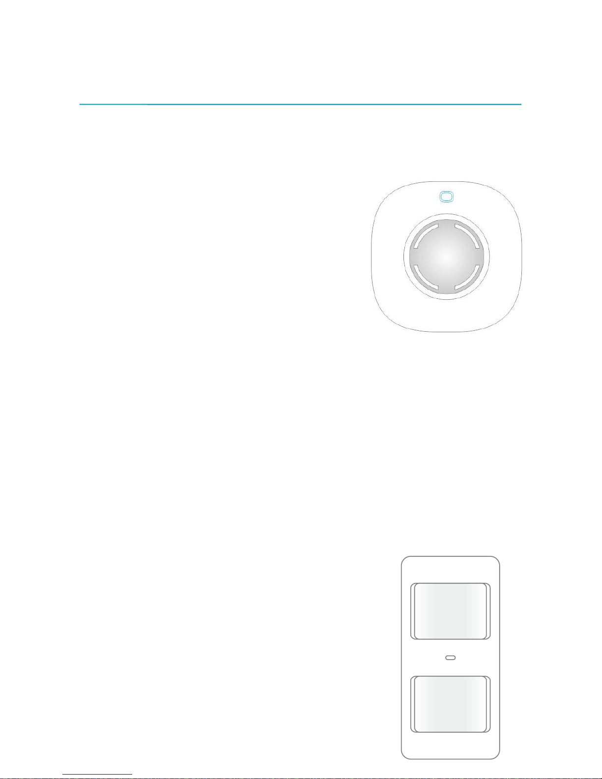
Control Unit (CU) x 1
The CU plugs directly into a suitable mains
power socket.
When an accessory is triggered, the built-in
siren will sound and the strobe light will flash
to alert you of intrusion into the protected area
and deter intruders.
Pet Friendly PIR Motion Sensor x 1
The Sensor incorporates fuzzy logic to minimize
false alarms from unwanted heat sources. With
the power saving feature, the Sensor will enter
into sleep mode after the second activation within
a 3 minute period, thereby saving power.
The Sensor features pet immunity for small
animals up to 25 kgs.
Page 9
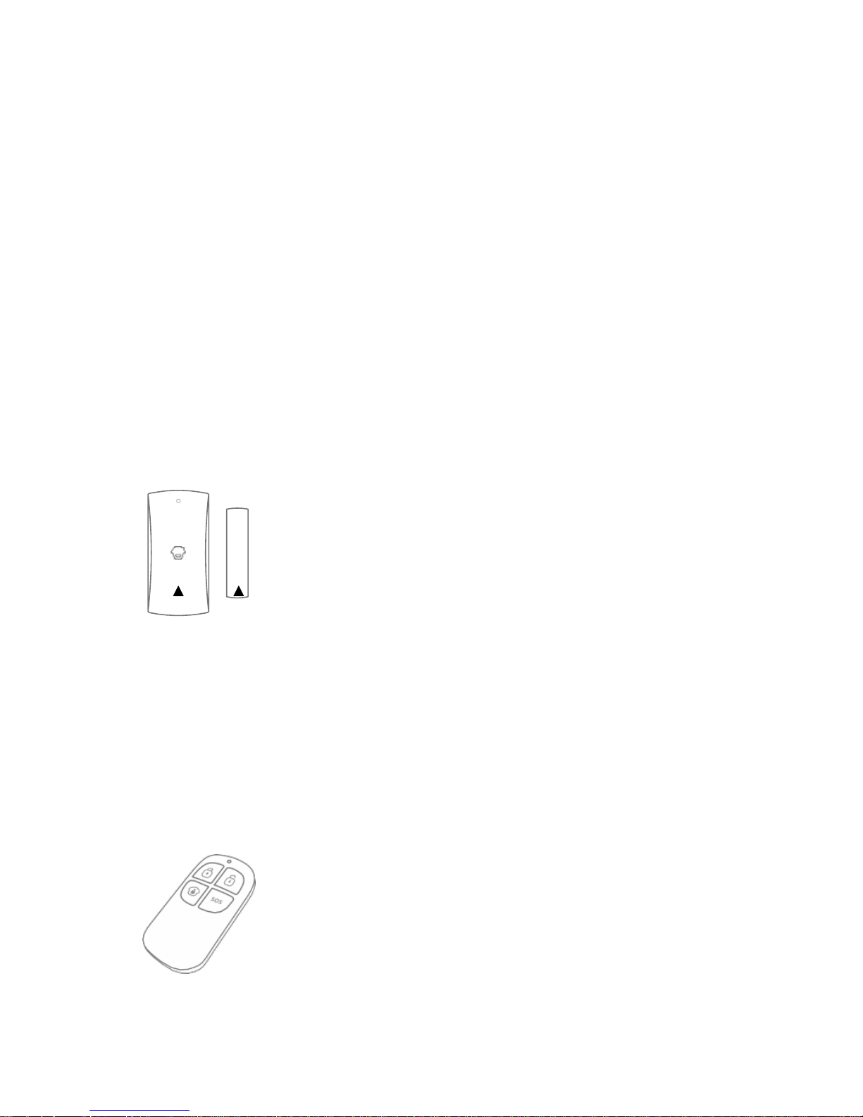
Wireless Door/Window Sensor x 1
The Door/Window Sensor can be fitted to doors, windows
and any other objects that open and close. The Contact
transmits signals to the Control Unit when the Magnet
mounted adjacent to the Contact is moved away.
Contact Magnet
Keyfob Remote Control x 2
The Remote Control is compact and includes a clip for
attaching to a key-chain/fob. The Remote Control is used
to arm, disarm and part-arm the system, and also to trigger
an emergency alarm (SOS).
Page 10

PIR Motion Sensor Bracket x 1 Double-sided tape for
Door/Window Sensor x 2
User Manual x 1 Screws and Wall Plugs x 3
3
Page 11
Control Unit Operation
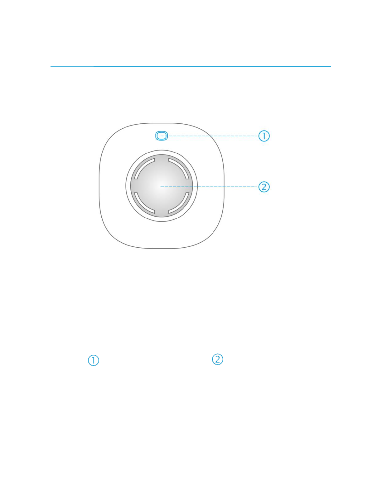
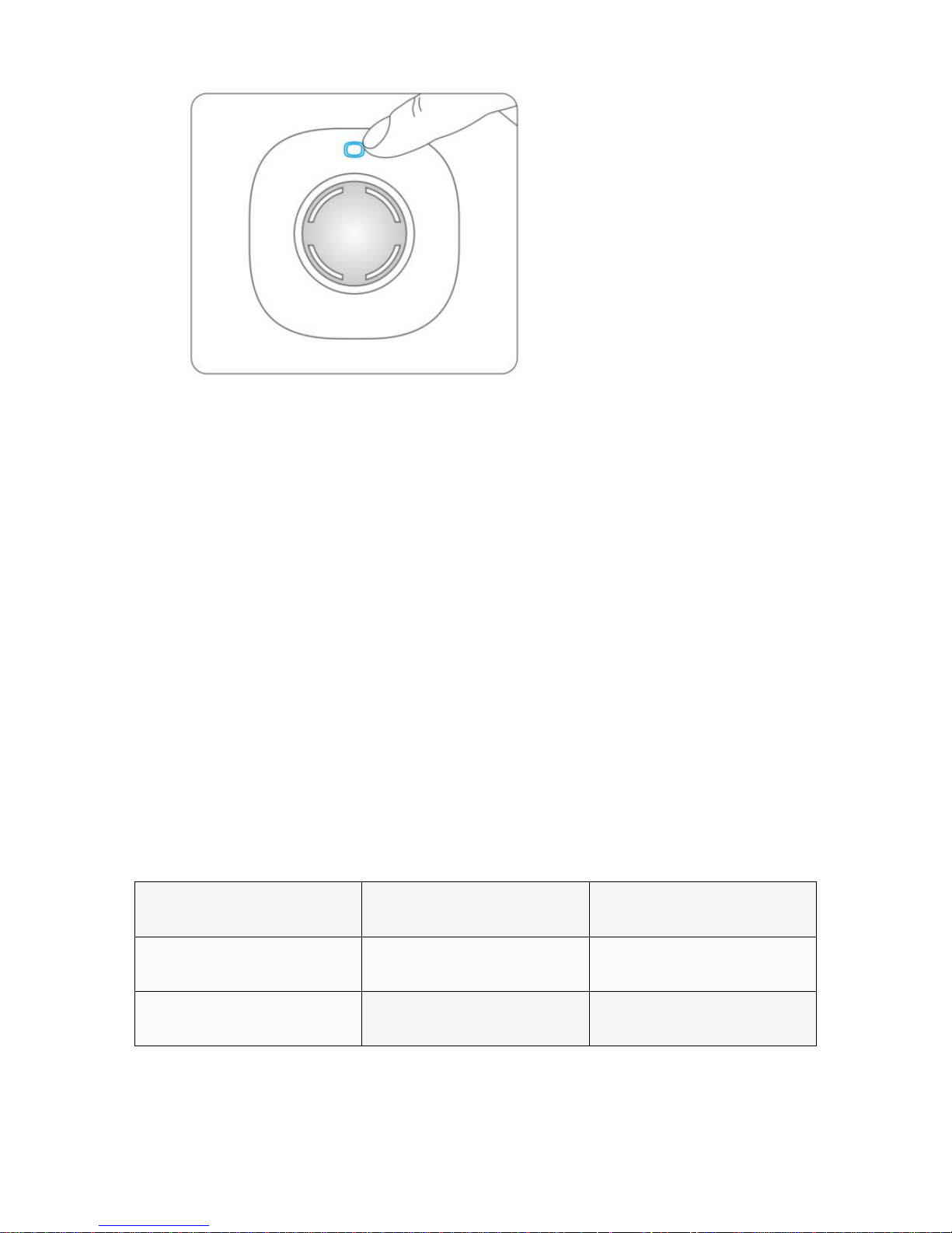
Control Unit (CU)
Power/Learn Button Strobe Light
Power On
The Control Unit is set to ‘off’ by default.
To enable the Control Unit, plug the unit into a suitable power outlet and
press the power/learn button, it will beep once indicating that it is enabled.
Page 12
Power Off
To turn the Control Unit ‘off’ press the power button once. Then press and hold
the power button for 6 seconds until a beep is heard, indicating that the Control
Unit is ‘off’.
Beeps and Strobe Light
Status
Control Unit
Strobe Light
Arm or Home Arm
Beeps Once
Comes On and Stays On
Disarm
Beeps twice
Flashes Twice, then Off
4
Page 13

Mute Arm
No Beep
Lights Up
Mute Disarm
No Beep
Light Goes Off
5
Page 14

Setting Entry and Exit Delays
The Sensors should be set in single delay zone before using this function.
Please refer to ‘Grouping Sensors’ on page 10.
Entry Delay (Alarm Delay)
When the Sensors which have been set to single delay zone are triggered, the
Control Unit will alarm after the delay time. If the Sensors that are set to normal
zone or home mode zone are triggered, the Control Unit will alarm immediately.
Press the connect button twice = 15 second delay
Press the connect button three times = 30 second delay
Press the connect button four times = function disabled
Note: Press the button on the Remote Control twice, the system switches to armed
status immediately. For single delay, refer to page 10.
Exit Delay (Arm Delay)
Page 15

The whole alarm system enters armed status after the delay time.
6
Page 16

Connecting and Deleting Accessories
Accessories need to be paired to the Control Unit so that it can receive signals
from them, and sound the alarm. The kit accessories are pre-learnt to the
Control Unit and are ready for use. If the Control Unit does not sound when
the Sensors are triggered, please pair them again. Accessories purchased
separately must be paired to the Control Unit before use.
Pairing a Remote Control
(1) Press the power/learn button on the Control Unit
The Control Unit will beep once, 3 seconds later it will beep once again and
the strobe will flash, the Control Unit is now ready for pairing.
(2) Press any button on the Remote Control
Press any button on the Remote Control, the Control Unit will beep once
indicating successful pairing.
Page 17

Note: if the Control Unit beeps twice, it indicates that the Remote Control has been paired before.
7
Page 18
Pairing a Door/Window Sensor
(1) Press the power/learn button on the Control Unit
The Control Unit will beep once, 3 seconds later it will beep once again and
the strobe will flash, the Control Unit is now ready for pairing.
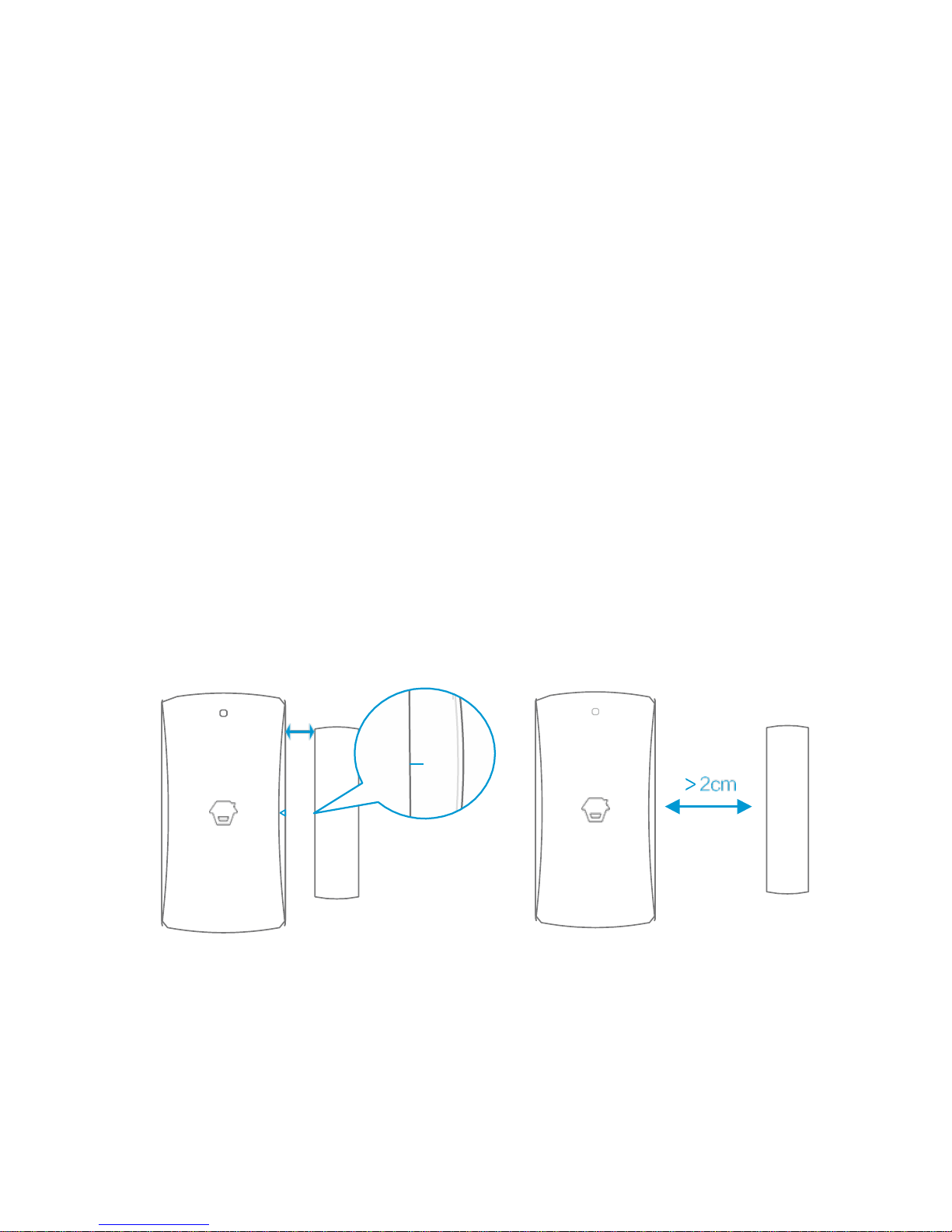
(2) Separate the Transmitter and Magnet
Make sure that the triangle marks on the Transmitter and Magnet are facing
each other and less than 1cm apart, then separate them to more than 2cm
apart. The Control Unit will beep once to indicate successful pairing.
Note: if the Control Unit beeps twice, it indicates that the Door/Window Sensor has been paired
before.
< 1cm
8
Page 19
Pairing a PIR Motion Sensor
(1) Press the power/learn button on the Control Unit
The Control Unit will beep once, 3 seconds later it will beep once again and
the strobe will flash, the Control Unit is now ready for pairing.
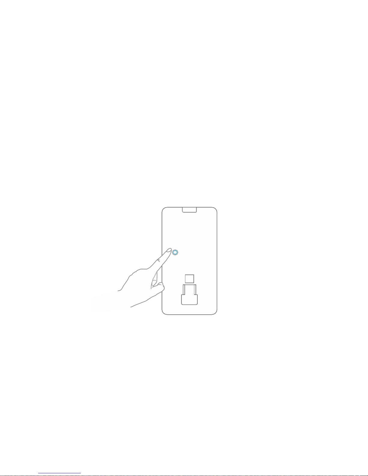
(2) Press the test button on the PIR Motion Sensor
Press the test button at the back of the PIR Motion Sensor. The Control Unit
will beep once, indicating successful pairing.
Note: if the Control Unit beeps twice, it indicates that the PIR Motion Sensor has been paired before.
Deleting Accessories
Page 20

To disconnect accessories from the Control Unit, press and hold the
power/learn button on the Control Unit for 6 seconds. The Control Unit will
beep once and the strobe flash twice, indicating that all the accessories have
been deleted
9
Page 21
Grouping Sensors
Each Sensor can be set to a different mode. Four different modes can be selected;
Home Mode. Normal Mode, Single Delay Mode or 24-hour Mode.
Important:
(1) Determine which Mode each Sensor should be set to prior to commencing
installation.
(2) If you change the Mode a Sensor is set to, re-register the Sensor to the Control
Unit.
The diagrams below show the four different Mode Settings that can be set up to
each Sensor.
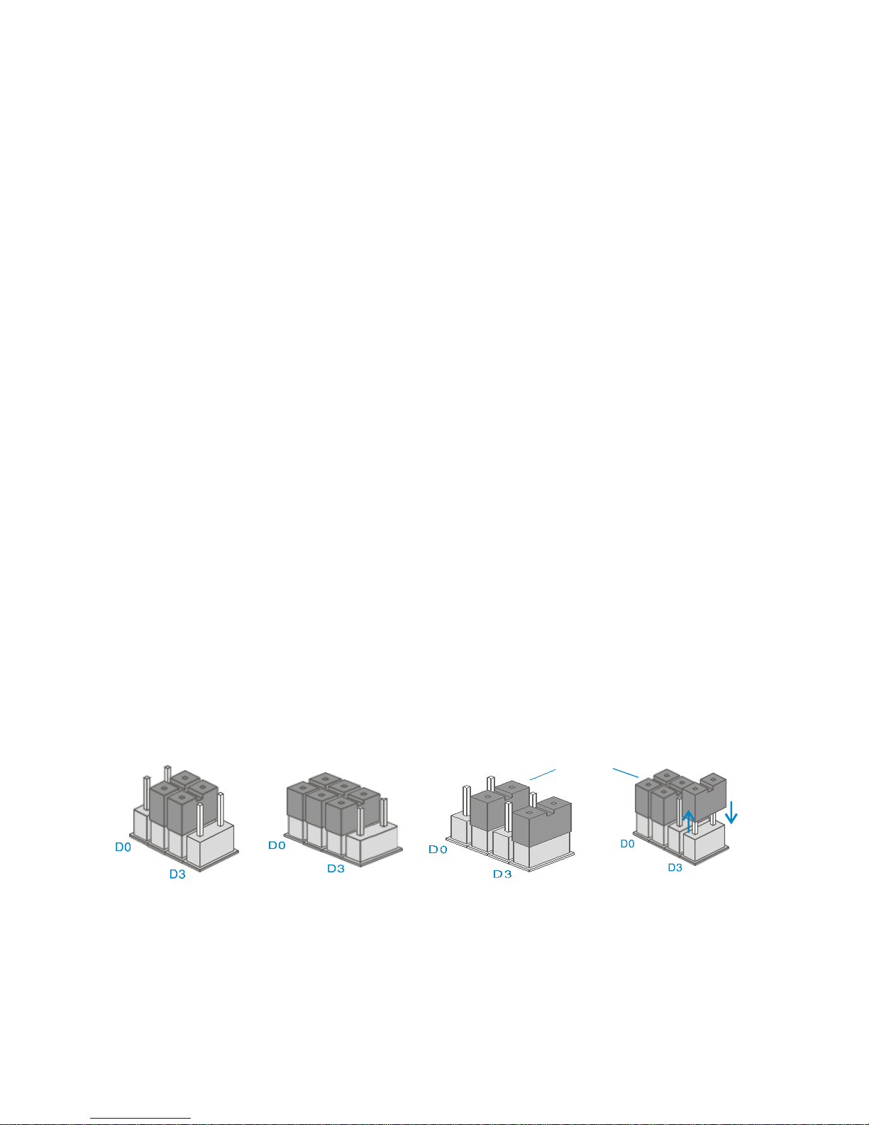
Inside the Sensor are 3 ‘bridges’. The configuration of the bridges will dictate the
Mode that the Sensor is set to. To change the Mode, simply re-position the ‘bridges’
by lifting them up and away from the pins and then push them down onto the pins
in the relevant position required.
Home Mode Normal Mode Single Delay Mode
(delay time)
24-hour Mode
Normal Mode: The supplied Door/Window Sensor is by default set to Normal Mode
bridges
Page 22

with bridges set on D0, D1 and D2. When triggered, a Sensor set to Normal Mode will
always activate the alarm if armed.
Home Mode: The supplied PIR Motion Sensor is (by default) set to Home Mode (D1
and D2). Sensors set to Home Mode will not be active when the alarm system is
part-armed. Part-Arm allows you to arm certain areas but not others. For example,
by setting sensors upstairs to Home Mode, when you part-arm the system at night
time you and your family can move around upstairs, whilst all other areas are protected.
10
Page 23

Sensor Placement
When planning your Alarm System installation consider the most vulnerable areas
of your home such as exit/entry routes - well placed Sensors will ensure optimum
security coverage.
The diagram below shows the areas within your home that you would typically
want to protect. Additional miGuard Accessories can be added at any time for
maximum coverage of your home and outbuildings.
A. Control Unit B. Remote Control C. Siren D. Dummy Siren
1. Front Door
2. Living Area
3. Window: living area
4. Window: living area
5: Patio/Garden door
6. Window: bedroom area
7. Bedroom
8. Kitchen
9. Bathroom
10. Bedroom
D
Page 24

11. Hall Ceiling : Door/Window Sensor
: PIR Motion Sensor
: Door/Window Sensor
: Door/Window Sensor
: Vibration Sensor
: Door/Window Sensor
: PIR Motion Sensor
: Smoke Sensor
: Water/Flood Sensor
: Mini Strobe Siren (plug-in)
: Ceiling Mounted PIR
11
Page 25

Remote Control
Overview
Arm
Part Arm
LED Indicator
Disarm
Panic
Arm (Away Mode)
Page 26

Press the button. The Control Unit will beep once indicating that the
system is armed.
12
Page 27

Press the button. The Control Unit beeps twice, indicating the
system is
disarmed.
Part-Arm (Stay/Home Mode)
Press the button, 3 seconds later the Control Unit will beep once,
indicating that the system is in Home Mode.
When the whole system is in Home Mode, all of the Sensors in ‘normal zone’ are
Disarm
Page 28

armed except those in Home Mode Zone, while the Home Mode Sensors are in
disarmed status users can move freely within the range of the disarmed area.
Note: Home Mode requires the home zone setting on Sensors (see pages 10)
13
Page 29

Mute Operation
Press and hold the button for 1 second, then press the button
within 3 seconds. The system is armed silently. Press and hold the
button for 1 second, then press the button within 3 seconds. The
system is disarmed silently.
SOS
Page 30

Press the button on the Remote Control, the system will alarm immediately.
14
Page 31

Nightlight On/Off
Press the button twice, the Control Unit switches to Home Mode
silently and the nightlight is on.
Press the
button twice, the Control Unit disarms and switches
off the nightlight.
15
Page 32

Door/Window Sensor
Overview
LED Indicator
Transmitter Magnet
LED Indication
Status
Meaning
Blinks once
Door/Window Sensor triggered
Page 33

AA 1.5V LR6
Tamper Switch
Zo
Blinks once every 3 seconds
Low power indication, please replace battery
immediately
PCB Layout
ne Setting/Group Setting
16
Page 34

Test
To test Sensor operation:
1. Remove the battery isolation strip - the Sensor will power up
2. Position the triangle marks on the Transmitter and the Magnet to face each
other, less than 1cm apart.
Page 35

< 1cm
17
Page 36

3. Press the button on the Remote Control - the system switches to
armed status. Move the transmitter at least 2cm away from the magnet,
the alarm will trigger indicating that the Sensor is working.
Installation
Ensure that the Sensor works properly before installation. There are triangle marks
on the side of the Transmitter and Magnet. Make sure that the triangle marks are
facing each other to within 1cm. If the space between the Transmitter and Magnet
is over 2cm the LED on the transmitter will illuminate, in this case reduce the
distance between the Sensor and Magnet until the LED is not illuminated.
Option 1: Using the double-sided sticky pads supplied
Peel away one side of the backing tape and firmly press the pad in place onto
the back of the Transmitter. Remove the remaining backing tape, position the
Transmitter in place (for example, window or door frame) and press firmly in
18
Page 37

place. Following the same procedure for the Magnet.
Page 38

Option 2: Using screws (supplied only with the PMR1 Accessory Pack)
(1) Remove the rear cover (2) Choose a suitable installation location
Press the rear cover and
slide down to remove.
Place the Transmitter on the Door/Window
frame and the Magnet on the adjacent edge
of the Door/Window.
(3) Tighten the screws
Follow the sign. Push the
screws through the tiny holes.
Tighten the screws.
(4) Close the rear cover
Slide the Transmitter down until it secures.
Align the Magnet to the Transmitter.
Note: Make sure that the Transmitter and Magnet operate correctly prior to
Page 39

permanently fixing in position
19
Page 40

PIR Motion Sensor
Overview
1. Detection Window
2. LED Indicator
3. Snap Joint
4. Test Button
5. Bracket
LED Indication
LED Status
Meaning
Blinks continuously
Self-testing
Blinks once
Motion is detected
Page 41

Blinks twice
Testing mode is finished, enters power
saving mode
Blinks one per 3
seconds
Low battery. Please replace the batteries
immediately
20
Page 42

PCB Layout
LED ON / OFF
Infrared Sensor
(Jumper Switch)
Tamper Switch
Infrared Sensor
Zone / Group Setting
Working Mode
Once the PIR is powered up it will enter self-testing Mode for 10 - 30 seconds.
Test Mode
After self-testing, press the test button, the Sensor switches to test mode and
detects once every 10 seconds. After 3 minutes, the LED blinks twice and the
Sensor switches to power saving mode.
Page 43

21
Page 44

Power Saving Mode
If the Sensor detects human body movement twice within 3 minutes, it will switch
to sleeping state to save power. During that time, the LED will not blink and the
Sensor will not trigger an alarm. When no movement is detected in the next 3
minutes, the Sensor switches itself back to working status automatically.
Note:
When the Sensor is in Sleep Mode make sure there is no human body movement
within 3 minutes in order to prevent the Sensor remaining in Sleep Mode.
In Sleep Mode, it is recommended that you leave the room for 3 minutes after
arming the system, then return to the room when you will hear the Siren sound
immediately.
Detection Scope
Case 1:
Initial power up
Initial power up
Test button pressed afterwards
Sleep Mode after detecting
No human movement
Switch from sleep to arm state
Case 2:
Page 45

Top View
Side View
22
Page 46

Test
To test that the PIR Sensor has been successfully linked to the Unit:
1) Remove the insulating strip
Press the snap joint to open
the rear cover, then remove
the insulating strip.
2) Arm the system
Press the button on
the Remote Control. The
system is now in an arm
mode.
3) Trigger an alarm
Page 47

Keep pressing the Test Button at the back of the PIR until the siren
sounds, indicating that the PIR Sensor has been paired to the
Control Unit.
23
Page 48

Installation
After making sure that the Sensor operates properly, follow the steps below:
1) Choose a suitable installation location
For installation tips, please see pages 21 & 22
2) Fit the PIR Sensor
Assemble the wall bracket and the ball then fix to the wall in the desired location.
Offer up the PIR to the ball plate, locating the cut-out of the PIR onto the ball plate
and click into place.
Ground
Page 49

24
Page 50

Installation continued
3) Test the PIR Sensor
Press the test button. The Sensor will switch to test mode for 3
minutes. Walk into the detection area and observe the LED
indicator. When human body movement is detected the LED will flash
once.
4) Adjust the angle
If you are not fully satisfied with the test results, you can easily
adjust the angle of the bracket to achieve the desired detection
range.
Side view Top view
Page 51

Note:
If protecting an area with pet access, do not adjust the angle up or down, keep
the PIR parallel to the wall.
25
Page 52

Installation Tips
Sensor location:
Position Sensors to cover exit/entry points and at the recommended height of 2
metres above ground level.
Mounting the Sensor - Angle
The installation angle directly affects sensitivity. Sensitivity is optimal when the
walk direction is vertical to the infrared direction - example detection scope diagram
below:
26
Page 53

Avoid facing glass doors or windows:
Strong light interferes with detection
sensitivity. In some situations movement
directly outside the window (a stream of
traffic or people) may affect the system.
Avoid facing or positioning close to
heat/cold sources:
Heat/cold sources such as heat extraction
units, air conditioning units, heaters,
microwave ovens or refrigerators may
cause false alarms.
Avoid facing opposite/near to moving
objects:
Movement from nearby items, such as
curtains may trigger false alarms.
Page 54

If it is necessary to fit two Sensors within
the same range of detection, ensure they
are positioned so that there is no cross-
interference.
27
Page 55

When used as an Accessory Kit
The A105 can be used to extend any miGuard Alarm System (with Control Panel).
When used as an accessory the A105 Control Unit is referred to as an Internal
Siren.
Pairing the Internal Siren to a miGuard Control Panel:
Press the connect button on the Internal Siren - the Internal Siren will beep once,
3 seconds later it will beep once again and the strobe will flash indicating that the
internal siren is in learn mode, ready for pairing.
Press the or button on the Internal Siren, it will beep once to
indicate successful pairing.
Exit Pairing Status
Press the connect button on the Internal Siren, it will beep once indicating that it
is no longer in pairing status.
Test Internal Siren Pairing Status
Press the button on the Remote Control. If the Internal Siren and Control
Panel both beep once, pairing was successful. If not, follow the above steps again.
28
Page 56

Pairing Other Wireless Sensors to a miGuard Control Panel:
After the Control Panel enters into pairing status (please refer to the user
manual related to the control panel), trigger the wireless Sensor. The Control
Panel will beep once to indicate successful pairing.
Deleting the Internal Siren from a miGuard Control Panel:
Please refer to the specific Control Panel instruction manual.
Deleting Accessories from the Internal Siren – when used as a Control
Unit
Press and hold the connect button on the Internal Siren for 6 seconds. The Siren
will beep once and the strobe will flash twice, all accessories are now deleted.
29
Page 57

Specifications
Control Panel: A105
Power Supply
AC 100~240V, 50/60Hz
Backup Battery
3.7V 600mAh lithium battery
Volume
90dB
Static Current
≤13mA
Alarm Current
≤100mA
Radio Frequency
315MHz or 433.92MH(±75KHz)
Housing Material
PC+ABS plastic
Operating condition
Temperature -10℃~+55℃
Relative Humidity ≤ 80% (non-condensing)
Dimensions (LxWxH)
Page 58

90 x 90 x 42.2mm (Not include the plug part)
30
Page 59

Wireless Remote Control: RC80
Power Supply
DC 3V (CR2025 lithium battery x 1pc)
Transmitting Current
≤7mA
Transmitting Distance
≤80m (in open area)
Radio Frequency
315MHz or 433.92MH(±75KHz)
Housing Material
ABS plastic
Operating condition
Temperature -10℃~+55℃
Relative Humidity ≤ 80% (non-condensing)
Dimensions (LxWxH)
58 x 31 x 9.5mm
31
Page 60

Wireless Door/Window Sensor: M102
Power Supply
DC 1.5V (AA 1.5V LR6 Battery x 1pc)
Static Current
≤35uA
Alarm Current
≤40mA
Transmitting Distance
≤80m (in open area)
Radio Frequency
315MHz or 433.92MH(±75KHz)
Housing Material
ABS plastic
Operating condition
Temperature -10℃~+55℃
Relative Humidity ≤ 80% (non-condensing)
Transmitter Dimensions (LxWxH)
71 x 34 x 17.5mm
Magnet Dimensions (LxWxH)
51 x 12 x 13.5mm
32
Page 61

Pet Friendly PIR Motion Sensor: P910
Power Supply
DC 3V (AA 1.5V LR6 Battery x 2pcs)
Static Current
≤90uA
Alarm Current
≤9.5mA
Detection Scope
8m/110°
Transmitting Distance
≤80m (in open area)
Radio Frequency
315MHz or 433.92MH(±75KHz)
Housing Material
ABS plastic
Operating condition
Temperature -10℃~+55℃
Relative Humidity ≤ 80% (non-condensing)
Detector Dimensions (LxWxH)
108 x 52 x 36.8mm
Bracket Dimensions (LxWxH)
52 x 30 x 26.5mm
33
Page 62

Page 63

Page 64

Page 65

Page 66

Page 67

备注:
产品型
号
A105
部件
名称
说明书
设计
林寿
材质
80g 书写纸
印刷尺
寸
232.2*166
.5mm
成品
尺寸
116.1*166.5
mm
工艺
骑马钉 40P,
四色双面印刷
文件最后一页为封底。
Page 68

 Loading...