

Page 1

INSTALLATION AND
OPERATING MANUAL
VIDEO INTERCOM
WIRELESS TWO-WAY SYSTEM
Version 1.0
Page 2

Page 3
Page 4

IMPORTANT
PLEASE READ THIS MANUAL CAREFULLY BEFORE OPERATING
THE SYSTEM AND RETAIN FOR FUTURE REFERENCE.
All devices, with the exception of the external siren are suitable for mounting
in dry interior locations only.
Any repairs must be carried out by an Authorised Repair Centre. Misuse
or attempted repairs to a component part of the product will invalidate the
warranty. The photocopying, copying, reproduction, translation to any language,
modification, storage in a retrieval system or retransmission, in whole or in part,
in any form or by any means, electronic, mechanical or otherwise of this manual,
is strictly prohibited without the prior written permission of ERA Home Security.
Disposal and Recycling
Disposal of this product is covered by the Waste Electrical or Electronic Equipment
(WEEE) Directive. It should not be disposed of with other household or commercial
waste.
At the end of the product’s useful life, the packaging and product should be
disposed of via a suitable recycling centre. Please contact your local authority or the
retailer from where the product was purchased for information on available
facilities.
Declaration of Performance
This equipment complies with the essential requirements of the Radio and
Telecommunications Terminal Equipment Directive, 1999/5/EC.
Additional Accessories
This can easily be extended at any time with the range of ERA Wireless Alarm
Accessories for details visit www.erahomesecurity.com or call our Customer
Support team on 0345 257 2500 (local call rate).
Page 1
Page 5

TABLE OF CONTENT
Kit Contents
1. Get to know your product
1.1 Features
2. Installation
2.1 Video Handset Battery Installation
2.2 Outdoor Camera Battery Installation
2.3 Charging the Video Handset
2.4 Connecting the Outdoor Camera to a power supply
and/or unlock module (optional accessories)
3. Settings
3.1 Volume (9 Levels)
3.2 Brightness (9 Levels)
3.3 Key Tone
3.4 Ring Tone
3.5 Auto Snap Settings
3.6 Snap Show
3.7 Date & Time
3.8 Door Set
3.9 Language
3.10 Wallpaper (3 Styles)
3.11 Register
3.12 Software Version
3.13 Default Settings
4. Setup
4.1 Registration
4.2 De-registration
5. Operation
5.1 Outdoor Camera Operation
5.2 Unlocking
5.3 Monitoring
5.4 Tamper Alarm
5.5 Backlight
3
3
4
5
5
6
6
7
9
10
10
10
11
11
11
12
12
13
13
13
13
13
14
15
15
15
16
16
16
16
16
6. Specification
7. Additional Accessories
Notes
ERA Product Guarantee
17
17
18
19
Page 2
Page 6

KIT CONTENTS
Video Handset x 1
Lithium Battery x 1
Charger Base x 1
Power Adapter
(12V, 500mA) x 1
When unpacking your video intercom please check that all parts are present.
If you have any queries regarding your purchase please contact our customer support
helpline, prior to installation and set-up.
Outdoor Camera x 1
Battery Cover x 1
Cable Cover x 1
Bracket x 1
1. GET TO KNOW
YOUR PRODUCT
Wireless Video Handset
Left Soft Key
Accept Key
Page 3
LCD Display
Navigation Key
Monitor/Snapshot
Power/End Key
Unlock Key/
Charger LED
Microphone
Speaker
Battery
Compartment
Cover
Charging Pins
Page 7
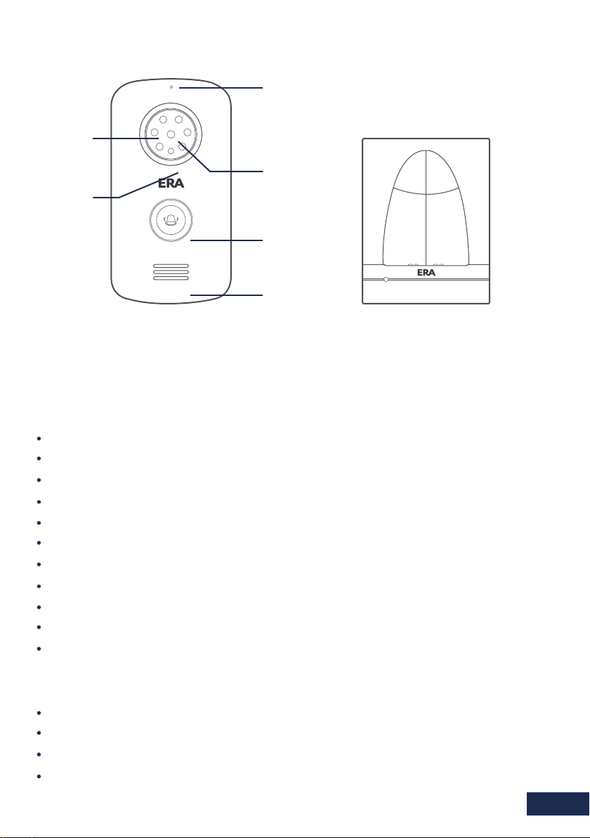
Outdoor Camera
Microphone
Charge Base
LED Lights
Camera
Sensor Light
Call Button
Speaker
1.1 Features
Up to 500 metres operating range in clear line of sight. Supports up to 2 outdoor cameras
and 2 video handsets.
Wireless Outdoor Camera/Intercom/Doorbell
Battery operated (requires C Cell batteries x 2, not included)
Power supply option (requires DC 12V Power adapter, not included)
IP55 rated
8 LEDs for night vision
Video resolution: 320x240, 15 frames per second
Wide angle lens - 120 viewing angle
Auto snap feature - stores up to 100 snaps
Backlit call button (doorbell)
Talk with the person at the video handset
Monitoring feature
Tamper protection
Wireless Indoor Video Handset
2.4” TFT LCD display
Adjustable brightness and talk volume
See, hear and talk with the visitor at your door
Monitoring feature
Page 4
Page 8
2. INSTALLATION
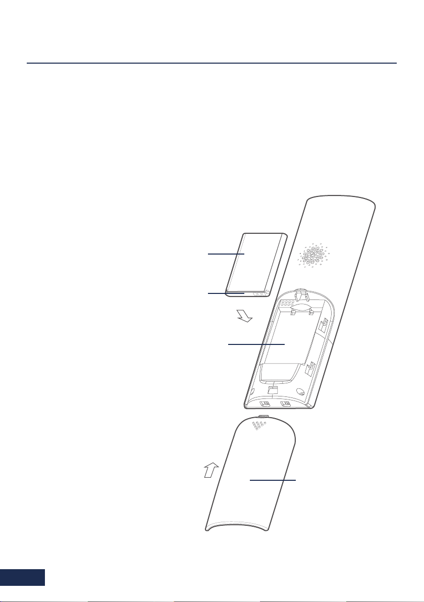
2.1. Video Handset Battery Installation
Fit the rechargeable lithium battery (3.7V, 1100mA) supplied as follows -
Remove the battery compartment cover by pushing down on the raised arrow and
1.
sliding the cover in a downward direction.
Remove the battery’s protective film and
2.
insert the battery into the battery
compartment, taking care to
correctly match the polarity (+, -).
3.
Replace the battery cover
by sliding it upwards until
it snaps into place.
Lithium
Battery
The status of the handset
battery is shown in the top
right-hand corner of the
screen when in standby
mode.
Note:
1. Should the battery not reach its full
storage capacity after recharging,
replace with a new battery.
2. When replacing the battery use
only an equivalent lithium
battery.
DO NOT use any other battery type.
Protective
Cover
Battery
Case
2.
1.
Battery
Compartment
Cover
Page 5
Page 9

2.2. Outdoor Camera Battery Installation
Screw
1. Fit two ‘C’ size 1.5V batteries (not supplied)
into the battery compartment.
Fix the battery cover in place using the four
2.
screws provided.
The status of the outdoor camera batteries is
shown in the top left-hand corner of the screen
when in monitoring mode and during a call.
2.3. Charging the Video Handset
Battery
Cover
Batteries
Connect the modular end of the AC power adapter to the power jack of the charger,
then plug the AC adapter into a suitable mains socket. Fully charge the handset prior
to initial operation (approx. 5 hours).
Note: When the handset is charging, the ‘Unlock’ button will be illuminated.
Page 6
Page 10

2.4. Connecting the Outdoor Camera to a Power Supply and/or
Unlock Module (optional accessories)
Connection Mode 1 Normally ‘Open’
EX-BUT
DC9 12V
GND
DC Power Supply
Outdoor Camera
Connection Mode 2 Normally ‘Closed’
DC9 12V
GND
DC Power Supply
GND
DC9 12V
GND
DC9 12V
NC
NO
COM
DC power
for lock
Maximum Relay Output
Current 1A
EX-BUT
NC
NO
COM
DC power
for lock
Maximum Relay Output
Current 1A
Normally
open lock
Lock
Normally
closed lock
Lock
Outdoor Camera
Note: The outdoor camera can be either battery powered or mains powered by compatible
AC adapter (not supplied). Do not use both batteries and an AC adapter at the same time.
The call button backlight is only available when the outdoor camera is mains powered.
Page 7
Page 11

Cable Cover
After wiring a power supply and/or
unlock module (not included) to
the connection terminal, tension
the cable. Fit the cable cover over
the connection terminal with the
Cable
four screws supplied.
Battery
Compartment
Cover
Connection Mode 1 Normally ‘Open’
When locating the outdoor camera, position the camera lens at an average ‘head height’.
Fix the bracket to the wall with the screws supplied and locate the outdoor camera onto
the wall bracket. Finally fit the anti-tamer screw.
Wall Plug
96
Anti-tamper Screw
Bracket Installation Screws Outdoor Camera
72
Page 8
Page 12

3. SETTINGS
Turning On/Off
To turn on the indoor handset press and hold .
To turn off the indoor hand, press and hold .
When you turn on the video handset, this screen will be
displayed.
Note: When the video handset battery is low the low battery
icon will be displayed on the screen and a warning tone
will sound. Replace the batteries with an equivalent type.
Setting the Volume & Brightness
To volume and brightness can be set when in standby mode and during a call.
From the ‘Home’ screen press Right or Left to increase/decrease the volume. To
increase/decrease the brightness press Up or Down
Setting up a Menu Function from the Video Handset
Press to select the Menu Screen. To view and edit a menu function scroll down
to select the required function, when highlighted press the Select key. Press Up ,
Down , Left or Right to set your chosen option, then press Select to set and
return to the main menu. To return to the main menu without making a change to
any function press the Back button.
1 5 : 3 6
Page 9
Page 13

3.1. Volume (9 Levels)
1. Press Up or Down to choose ‘Volume’ menu, then
press beneath Select.
2. Press Left , or Right to select the volume that you like.
3. Press beneath Select to save the settings and return to
the previous menu.
Note: Also, you can use Left or Right key to adjust the
volume in standby mode.
3.2. Brightness (9 Levels)
1. Press Up or Down to choose ‘Brightness’ menu, then
press beneath Select.
2. Press Left , or Right to select the light level that you like.
3. Press beneath Select to save the settings and return to
the previous menu.
Note: Also, you can use Left or Right key to adjust the
brightness in standby mode.
________
3.3. Key Tone
Each time you press a key a ‘key tone’ is heard. In certain
error conditions, for example when an incorrect key is pressed
a warning tone will sound.
1. Press Up or Down to choose ‘Key Tone’ menu, then
press beneath Select.
2. Press Up , or Down to select On or Off to enable or
disable the function.
3. Press beneath Select to save the setting and return to the
previous menu.
Page 10
Page 14

3.4. Ring Tone
1. Press Up or Down to choose ‘Ring Tone’ menu, then
press beneath Select.
2. Press Left , or Right to choose the ring tone. Each time
you press Up or Down the video handset will play the
selected ring tone.
3. Press beneath Select to save the settings and return to
the previous menu.
3.5. Auto Snap Settings
1. Press Up or Down to select ‘Snap Set’ menu, then
press beneath Select.
2. Press Up , or Down to choose On or Off to enable or
disable the function
3. Press beneath Select to save the settings and return to
the previous menu.
With ‘Auto Snap’ On. the camera will take a photo of visitor
automatically when the outdoor camera’s call button is pressed. Photos can be viewed
on the video handset in ‘Snap Show’.
Note:
1. To take a photo of your visitor during a conversation or when using the ‘monitoring’
feature, press the ‘Snap Key’ to save it to the video handset.
2. Up to 100 photos can be stored to the handset. Stored photos are sequentially
over-ridden when the number exceeds 100.
3.6. Snap Show
1. Stored photos can be viewed or deleted in the ‘Snap Show’
menu. The snap number is displayed in the upper right corner of
the photo.
1. Press Up or Down to select ‘Snap Set’ menu, then press
beneath Select.
2. Press Left , or Right to view photos.
3. To delete a photo press . In the centre of the screen ‘ ’?
will be displayed, press ‘ ’ at the bottom left of the screen to confirm deletion or ‘ x ’
at the bottom right of the screen to cancel. The next photo will be displayed.
4. Press beneath to return to the previous menu.
Page 11
√
Page 15

3.7. Date & Time
1. Press Up or Down to choose ‘Date & Time’ menu, then
press beneath Select.
2. Press Left , or Right to choose the hour or the minute and
press Up or Down to adjust
3. To set the date press Left or Right to select the date,
month and year, then press Up or Down to adjust.
4. Press beneath Select to save the settings and return to the
previous menu.
Note:
1. The time format is 24 hour. The date format is YYYY-MM-DD.
2. The Date and Time when the handset is first Hour-Minute-Year-Month-Date.
3. Set the date and time when the handset is first changed to ensure that the time recorded
to the photos are correct.
4. When the battery is changed the time and date will need to be set again.
3.8. Door Set
1. Press Up or Down to choose ‘Door Set’ menu, then
press beneath Select.
2. To toggle between the three functions (Volume, Ring Time,
Unlock Time) press Up or Down . Each setting can be
changed as follows:
- Volume (9 levels): press Left or Right to select
- Ring Time (between 1 and 15 seconds) press Left or Right
to select
- Unlock Time (between 1 and 9 seconds): if an optional ‘Unlock Module’ is fitted, the
unlock duration of the associated locking mechanism can be set by pressing Left or
Right .
3. To save each setting individually press beneath Select with each change as it is
made, at each stage you will return t the menu screen from where you return to the
menu change remaining settings. To change all settings without returning to the
previous menu, make the changes then press Select to accept all changes.
Note: When there are two video handsets connected to one outdoor camera, the
setting of the two handsets must be the same.
________
Page 12
Page 16

3.9. Language
1. Press Up or Down to choose ‘Language’ menu, then
press beneath Select.
2. Press Up , or Down to choose the corresponding language
(’0’ for English)
3. Press beneath Select to save the settings and return to the
previous menu.
3.10. Wallpaper (3 styles)
1. Press Up or Down to select a wallpaper and to confirm.
Press Back to exit the screen without making any changes to the
current wallpaper.
3.11. Register
Used to link the outdoor camera to a video handset, as described
on page 14.
3.12. Software Version
To check the software version press Up or Down to select
the ‘Version’ menu, then press to select. Press Back to return
to the previous menu.
0
1.0.0 20150731
3.13. Default Settings
This function allows you to reset the video handset to factory
settings.
1. press Up or Down to select the ‘Default Set’ menu,
then press beneath Select.
2. Press Up or Down to choose YES or NO to enable or
disable the function.
3. Press beneath Select to reset the settings or Back to
return to the previous menu.
After resetting, the video handset will return to standby mode.
Page 13
Page 17

4. SETUP
4.1. Register
1. Insert a small screwdriver or similar item into the depression just above the ‘ ’
symbol inside the outdoor camera battery compartment and depress the register
button with the screwdriver for 3 seconds. The unit will sound an indication tone
and the call button backlight will illuminate.
2. Press beneath Menu on the video handset, then select the register menu, press
Up or Down to choose the door camera that you want to connect (1-2 are
selectable), then press beneath ‘ ’ to confirm the setting. The outdoor camera
will automatically search for the video handset to be registered. When the video
handset sounds an indication tone, the outdoor camera and video handset are
registered successfully.
Battery Compartment
‘batteries not fitted’
Register
Button
3. Press beneath Menu, then select ‘Register’ menu. The system will enter into the
register interface indicating that the outdoor camera is successfully registered to the
video handset.
Note: If you reset the video handset to the factory default, all settings will revert to
factory settings.
Battery Compartment
‘batteries fitted’
Register
Button
Page 14
Page 18

4.2. De-registering
1. To delete the registration press beneath . The display will
show ‘ ’?, press beneath ‘ ’ to confirm or ‘ x ’ to cancel.
Press beneath to return to the main interface.
#
Note:
1. Outdoor camera registration can take up to 60 seconds.
2. Video handset registration can take up to 20 seconds.
3. Up to 2 outdoor cameras and 2 video handsets can be supported.
√
4.3. De-registering
1. The video handset is set to ‘power saving mode’ in order to obtain maximum battery
life from the outdoor camera when battery powered. When in power saving mode the
monitoring feature is not available.
2. To enable the monitoring feature when the outdoor station is powered by batteries
(not mains powered), press the ‘register’ button for 3 seconds, the outdoor camera
will enter into ‘register’ status , press the ‘register’ button again for 3 seconds, 3
‘bleeps’ will be heard. The outdoor camera will switch from ’power saving mode’,
under ‘registered’ status press the ‘register’ button for 3 seconds, the outdoor camera
will sound one long tone and revert to ‘power saving mode’, the monitoring feature
will no longer be available.
5. OPERATION
5.1. Outdoor Camera Operation
When the outdoor camera call button is pressed the corresponding video handset will ring
and an image of the visitor will appear on the video handset screen. If the call button is
pressed again the conversation will end.
1. To reject the call press to cancel the ringer and the video.
2. To enable the two-way conversation, press on the video handset (the ring tone will
stop). To end the conversation press on the video handset or the call button on the
outdoor camera.
Note:
1. Ring time lasts up to 15 seconds
2. Conversation time will last up to 45 second, the call will automatically disconnect.
Page 15
Page 19

5.2. Unlocking
To utilise the ‘unlock’ feature an unlock module (available separately) and the unlock
mechanism are required. When fitted, during a conversation or ‘monitor’ status, the
door can be unlocked for a set period of time by pressing the button on the video
handset (Note: this will end the call).
5.3. Monitoring
This feature will allow you to view the picture from the outdoor camera on demand.
1. In standby mode, press beneath ‘Mon’.
2. If only one outdoor camera is registered the LCD screen will automatically display
the picture from that outdoor camera.
3. If two outdoor cameras are registered the LCD screen will display 1# and 2#
Monitor. Press Up or Down to select the camera you wish to monitor, the press
beneath Select.
4. In monitoring mode, press Accept to enter into intercom communication.
Note: The maximum monitoring time is 45 seconds.
5.4. Tamper Alarm
When the outdoor camera is moved from its bracket, both the outdoor camera and video
handset will sound an alarm tone. To outdoor camera call button will be inoperable,
press or to stop the alarm tones.
Note: The alarm will sound for up to 5 minutes
5.5. Backlight
1. When the outdoor camera power supplied by DC 12V, the call button backlight will be
illuminated. During registration, calling, alarm, monitoring and intercom status, the
backlight will flash.
2. When the outdoor camera power is supplied by batteries and is in ‘power consumption’
mode, the call button will flash during activation (registration, calling, alarm, monitoring
and intercom status). The call button will not be backlit.
3. When the outdoor camera is powered by batteries and in ‘’power save’ mode, the
call button will flash only during activation (when the call button is pushed) and then
will stop.
Page 16
Page 20

6. SPECIFICATION
Outdoor Camera
Transmit Frequency Range
Data Rate
Transmitting Power
Modulation Type
Transmitting Distance
Image Sensor Type
Image Processing
Camera Pixels
White Balance
Viewing Angle (Diagonal)
LED
Power Requirement
Power Consumption
Operating Temperature
Dimensions
No. of indoor Handsets Supported
Video Handset
Receiving Frequency Range
Monitor
Data Rate
Receiving sensitivity
Demodulation Type
LCD Resolution
Transmitting Power
Power Requirement
Power Consumption
Operating Temperature
Indoor Monitor Dimensions
Charger Base Dimensions
No. of Door Cameras Supported
+9V-12V)±5%/2*LR14(C),1.5V batteries
500mA Max (Cells) 200mA Max (+12V DC)
Temperature -20°C ~ +55°C - Humidity 20% - 90% (Non-condensing)
BL-5C, 3.7V, 1100mA (lithium battery)
Humidity 20% - 90% (Non-condensing)
52.7mm x 188.2mm x 26.3mm
2.4GHz - 2.4835GHz
Colour CMOS Image Sensor
80mm x 160mm x 55mm
2.4GHz - 2.4835GHz
Temperature -10°C ~ +55°C
80mm x 95.2mm x 103.7mm
2.0Mbps
19dBm (TYP)
GFSK
Outdoor: ≥260m
H.264
640x480
Auto
120°
6 LEDs
Max.2
2.4 Colour LCD
2Mbps
85Bm
GFSK
320x240 (RGB)
19dBm (TYP)
400mA Max
Max.2
7. ADDITIONAL
ACCESSORIES
Additional accessories are available for the E3000 Video Door Intercom system including:
Additional handset and charger
Additional outdoor station
Outdoor station rain cover
Outdoor station power supply
Unlock module
Page 17
E3000HSC
E3000-OS
CLOSRC
CLOSPSU
CL3660UM
Page 21

8. NOTES
Disposal and Recycling
Disposal of this product is covered by the Waste Electrical or Electronic Equipment (WEEE)
Directive. It should not be disposed of with other household or commercial waste.
At the end of its useful life the packaging and product should be disposed of via
a suitable recycling centre. Please contact your local authority or the retailer
from where the product was purchased for information on available facilities.
Page 18
Page 22

ERA PRODUCT GUARANTEE
We at ERA firmly believe in the quality of our goods. Our technology achieves outstanding performance and
durability and we can therefore offer, in addition to your statutory rights, an additional limited guarantee.
In the event of any material defects in any product manufactured by us due to faulty design, materials and/or
workmanship, and which arise following correct installation and during normal use in accordance with our
instructions, as included in the product packaging, within the period of two years from the date of purchase,
we will either repair, provide a replacement, substitute with an equivalent product free of charge from our then
current range or refund in full the amount paid for the product at point of purchase.
Conditions
In order to take advantage of our guarantee, you must comply with the following conditions:-
1. This limited guarantee is not transferable and is extended only to, and is solely or the benefit
of, the original purchaser of the product. Please retain your dated sales invoice as proof of
purchase and forward this to us if you wish to make a claim under this guarantee.
2. Products must be installed, used and maintained in accordance with our instructions otherwise
the guarantee will be invalidated.
3. The product must not be damaged or modified in any way nor must it have been subjected to
any unauthorised repairs.
Exclusions
This guarantee does not cover:-
1. Periodic maintenance, repair and replacement of parts due to fair wear and tear.
2. Abuse or misuse, including but not solely limited to the failure to use this
product for its normal purposes or in accordance with ERA’s instructions on usage and
maintenance.
3. Failure of the product arising from incorrect installation or use not consistent with the
instructions supplied and the cost of any removal or installation of products.
4. Accidents, Acts of God, lightning, water, fire, public disturbances, improper ventilation, voltage
fluctuations or any cause beyond the control of ERA (Force Majeure).
5. Unauthorised modifications carried out to the product.
6. Damage caused by incorrect/improper use of supplied batteries.
7. Alteration to, deletion, removal or illegibility of the Serial Number as shown on the Product
Label.
8. Consumables: any damages so caused by the use of batteries not supplied by ERA.
9. Repair or attempted repairing by bodies who are not ERA authorised repairers.
10. Neglect.
11. The loss of any stored data on your product.
This guarantee is in addition to your contractual and statutory rights and does not affect your statutory rights.
To make a claim
Please contact Customer Support either by telephone on 0345 257 2500 or email support@erahomesecuritycom,
with full details of your claim. If your claim satisfies our Conditions and is not subject to any of our Exclusions,
we will agree with you the repair, replacement, substitution or refund of payment of goods. For product returns
you will be issued with a Return Authorisation Number (RAN). Please note: Returns will not be accepted unless
accompanied by a RAN.
*Terms and conditions apply.
Page 19
Page 23

Page 24

Customer Helpline:
0345 257 2500
www.erahomesecurity.com
ERA Home Security Ltd
Valiant Way, Wolverhampton,
West Midlands, WV9 5GB
email: support@erahomesecurity.com
 Loading...