

Page 1
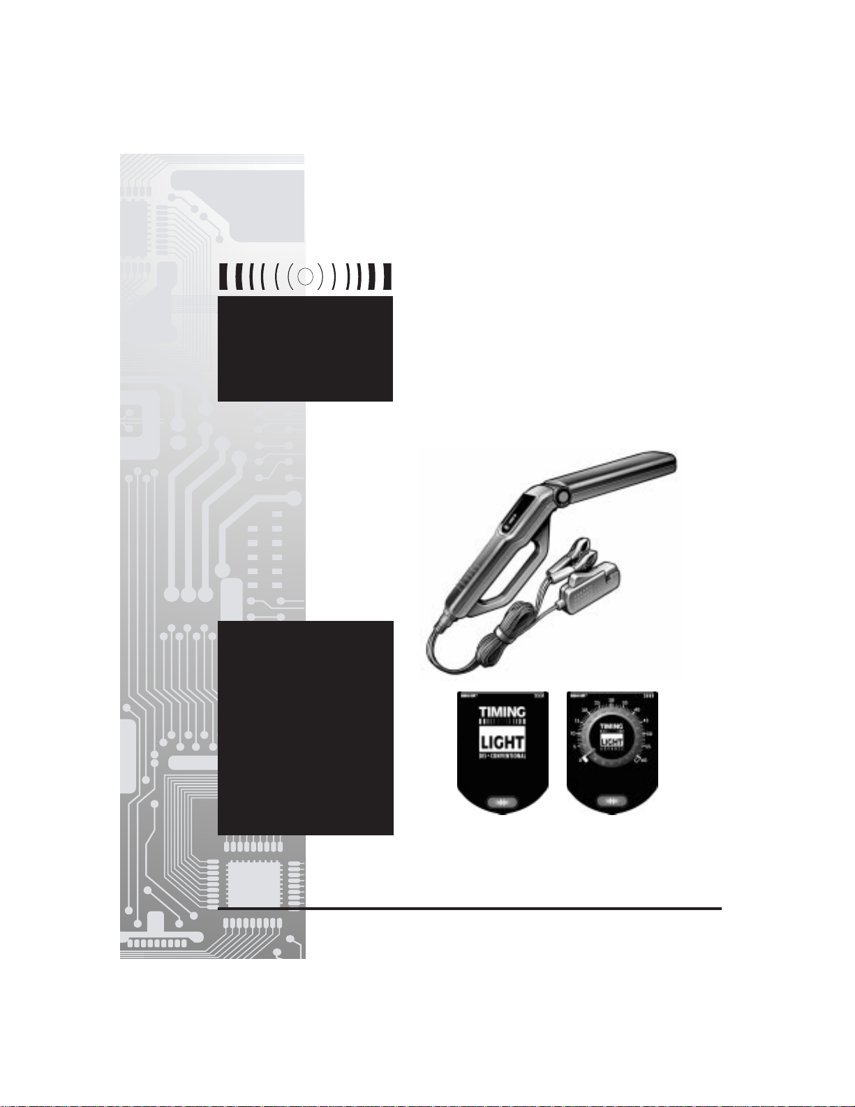
TIMING
L IGHT
OWNER’S MANUAL
• Works on:
- conventional,
- electronic,
- computer
controlled,
and
- DIS* ignition
systems.
* Model 3551 Only
Inductive Timing Light
Advance Timing Light
Page 2

TABLE OF CONTENTS
Paragraph Page No.
SAFETY GUIDELINES......................................................................................................................1
VEHICLE SERVICE MANUALS........................................................................................................2
GENERAL INFORMATION ...............................................................................................................3
ENGINE TIMING AND TUNE-UPS ........................................................................................3
ABOUT THE TIMING LIGHT..................................................................................................3
USING YOUR TIMING LIGHT ...........................................................................................................4
BEFORE YOU BEGIN............................................................................................................4
ENGINE PREPARATION BEFORE TIMING..........................................................................5
TIMING LIGHT CONNECTION ..............................................................................................5
INITIAL (BASE) TIMING CHECK ...........................................................................................6
TIMING ADJUSTMENT..........................................................................................................6
ADVANCE TIMING CONTROL CHECKS..............................................................................6
TROUBLESHOOTING.......................................................................................................................8
CARE AND MAINTENANCE.............................................................................................................9
CLEANING THE INDUCTIVE PICKUP ..................................................................................9
REPLACING THE INDUCTIVE PICKUP LEADS...................................................................9
WARRANTY AND SERVICE.............................................................................................................9
LIMITED ONE YEAR WARRANTY ........................................................................................9
SERVICE PROCEDURES......................................................................................................9
i
Page 3

SAFETY GUIDELINES
SAFETY EQUIPMENT
Fire Extinguisher
Keep a fire extinguisher suitable for
gasoline/chemical/electrical fires on hand
whenever working on a vehicle.
Fireproof Container
Store rags and flammable liquids only in
fireproof containers. Allow soaked rags to dry
thoroughly in open air before discarding.
Safety Goggles
Wear safety goggles when working on a vehicle
to protect your eyes from battery acid, gasoline,
and airborne dust and dirt from moving engine
parts.
LOOSE CLOTHING AND LONG HAIR
(MOVING PARTS)
Be very careful not to get your hands, hair or
clothes near any moving parts such as fan
blades, belts and pulleys or throttle and
transmission linkages. DO NOT wear loose
clothing or jewelry when working on a vehicle.
VENTILATION
ALWAYS operate vehicle in a well-ventilated
area. If vehicle is in an enclosed area, exhaust
should be routed directly to the outside using a
leakproof exhaust hose.
SETTING THE BRAKE
Make sure that your car is in Park or Neutral,
and that the parking brake is firmly set.
HOT SURFACES
Avoid contact with hot surfaces such as
exhaust manifolds, pipes, mufflers, radiator and
hoses. Never remove the radiator cap while the
engine is hot. Escaping coolant under pressure
can cause serious burns.
SMOKING AND OPEN FLAMES
Never smoke while working on your car.
Gasoline vapor is highly flammable, and the
gas formed in a charging battery is explosive.
BATTERY
Do not lay tools or equipment on the battery.
Accidentally grounding the battery's positive (+)
terminal can shock or burn you and damage
wiring, the battery or your tools and testers. Be
careful of contact with battery acid. It can burn
holes in your clothing and burn your skin or
eyes.
When operating any test instrument from an
external battery, connect a jumper wire
between the negative terminal of the external
battery and ground on the vehicle under test.
When working in a garage or other enclosed
area, the external battery should be located at
least 18 inches above the floor to minimize the
possibility of igniting gasoline vapors.
HIGH VOLTAGE
High voltage is present in the ignition coil,
distributor cap, ignition wires and spark plugs.
When handling ignition wires while the engine
is running, use insulated pliers to avoid a
shock.
JACK
The jack supplied with the vehicle should be
used only for changing wheels. Never crawl
under car or run engine while vehicle is on a
jack.
1
Page 4

VEHICLE SERVICE MANUALS
Contact your local car dealership, auto parts store, bookstore or public library for availability of
service manuals for your vehicle. The following companies publish valuable repair manuals. Write to
them for availability and prices. Be sure to include the make, model and year of your vehicle.
FACTORY SOURCES
Ford/GM/Chrysler/Honda/Isuzu/Hyundai/
Subaru Service Manuals
Helm Inc.
14310 Hamilton Ave.
Highland Park, Michigan 48203
Telephone (800) 782-4356
NON-FACTORY SOURCES
Haynes Publications
861 Lawrence Dr.
Newbury Park, California 91320
Telephone CA (800) 442-9637
TN (800) 242-4637
Mitchell International
14145 Danielson St.
Poway, California 92064
Telephone (888) 724-6742
IMPORTANT!
Motor Publications
5600 Crooks Rd., Suite 200
Troy, Michigan 48098
Telephone (800) 426-6867
Timing procedures vary from vehicle to vehicle. ALWAYS refer to the Vehicle Emission Label
or service manual for your vehicle to obtain the proper timing procedures, specifications, and
location of timing marks. OBSERVE ALL SAFETY PRECAUTIONS WHENEVER WORKING
ON A VEHICLE.
2
Page 5

GENERAL INFORMATION
ENGINE TIMING AND TUNE-UPS
Proper ignition timing is critical in order to
achieve peak engine performance and to
ensure maximum fuel economy. An ignition
system timing check is critical during any tuneup procedure. Your timing light provides a
simple and efficient means of checking your
vehicle's timing. The advance timing light
provides the additional ability to check the
operation of your vehicle's mechanical or
vacuum advance timing controls.
You may also need tools and equipment to
check engine rpm, breaker point dwell (for
conventional ignition systems), or to apply
vacuum to the vacuum advance diaphragm on
the distributor during advance checks. Your
supplier offers a wide range of tools and
equipment necessary to perform these tasks.
With reference to today's "self-tuning" vehicles,
the meaning of the term "tune-up" has changed
significantly. A tune-up consists essentially of
checking engine operation with Original
Equipment Manufacturer's specifications.
Adjustments are made and parts are replaced
ONLY if engine performance is not within
specifications.
ABOUT THE TIMING LIGHT
Your timing light is designed for use on all 12volt negative ground vehicles equipped with
conventional breaker point, and electronic
ignition systems or with DIS (distributorless
ignition systems). (DIS - Model 3551 ONLY)
NOTE
Some DIS systems are not adjustable.
Consult your vehicle's service manual for
procedures and specifications before attempting to time vehicles with DIS systems.
For 6-Volt Electrical Systems
■ Requires a separate 12-volt automotive
battery.
Your timing light may be used on vehicles
with 6-volt electrical systems by using the
following connection procedure:
1. Connect the RED battery clip to the
positive (+) terminal of the 12-volt
battery.
2. Connect the BLACK battery clip to
the negative (-) terminal of the 12-volt
battery.
3. Using a length of 18AWG jumper
wire, ground the negative (-) terminal
of the 12-volt battery to a known-good
ground on the vehicle under test.
4. Perform remaining connection and
test procedures as specified in the
appropriate sections of this manual.
Timing Light Controls
General controls for the Timing Light are shown
in Figure 1.
Fig. 1 Timing Light Controls - General
3
40
45
35
50
30
55
25
60
TIMING
E
C
20
N
A
V
LIGHT
D
A
2
1
15
10
5
0
3
4
Page 6

1. Xenon Bulb — Used to illuminate timing
marks for checking timing.
2. Swiveling Head — Contains the xenon
bulb. Rotates over approximately 90° to
allow for easy illumination of timing marks in
hard to reach locations.
3. Control Panel — Contains the controls
necessary to operate the Timing Light.
Specific controls vary between models.
Refer to the appropriate paragraph for a
description of control panel functions.
4. Inductive Pickup Leads — Detachable
leads assembly connects timing light to
battery and ignition system:
■ Red Battery Clip — Connects to
battery positive (+) terminal.
■ Black Battery Clip — Connects to
battery negative (-) terminal or bare
metal chassis ground.
■ Inductive Pickup Clip — Clamps
around No. 1 spark plug cable.
Operating controls for the Model 3551 Timing
Light are shown in Figure 2.
1. On/Off Switch — Press to turn timing
light on. Press again to turn timing light
off.
Operating controls for the Model 3555 Timing
Light are shown in Figure 3.
1. On/Off Switch — Press to turn timing
light on. Press again to turn timing light
off.
2. Advance Control Knob — Selects timing
light advance setting from 0° to 60°.
Fig. 2 Model 3551 Controls
TIMING
LIGHT
DIS • CONVENTIONAL
1
USING YOUR TIMING LIGHT
BEFORE YOU BEGIN
Make a thorough check before starting any test
procedure and fix any known mechanical
problems before performing any test. Loose or
damaged hoses, wiring, or electrical connectors
are often responsible for poor engine performance.
Refer to your vehicle’s service manual for
proper connection of vacuum hoses, electrical
wiring, and wiring harness connectors. Check
the following areas:
Fig. 3 Model 3555 Controls
30
25
TIMING
LIGHT
A D V A N C E
35
40
45
50
55
60
1
20
15
10
5
0
■ All fluid levels
■ Spark plugs and spark plug wires
■ Air cleaner
■ Vacuum hoses
■ Belts
■ Electrical wiring
■ Electrical connectors
2
4
Page 7

ENGINE PREPARATION BEFORE
TIMING
Always prepare the engine for timing before
performing a timing check. Refer to the Vehicle
Emission Control Label or service manual for
timing procedures and specifications for your
vehicle. The Vehicle Emission Control Label is
located under the hood in the engine
compartment. The label is typically located on
the underside of the hood, on a fender well or
valve cover, or near the hood latch.
As a minimum, make the following preparations
before timing:
1. Locate the timing mark and reference
pointer. The timing mark and pointer are
usually located on the crankshaft pulley or
vibration damper (on the front of the
engine) or on the flywheel (between the
engine and transmission). Refer to Figure 4.
Make sure the timing mark and pointer are
clean and clearly visible. Chalk the marks
if necessary.
2. Make sure all spark plugs are in good
condition and properly gapped.
3. Start and run the engine until it reaches its
normal operating temperature. TURN THE
ENGINE OFF BEFORE CONNECTING
TIMING LIGHT.
Fig. 4 Typical Timing Marks
14 BTDC
10
6
0 TDC
6 ATDC
0
10 20 30
If applicable, check and adjust dwell to
manufacturer's specifications.
TIMING LIGHT CONNECTION
To ensure personal safety and reliable
operation of the Timing Light, use the following
procedure to connect the Timing Light:
WARNING!
Always keep hands, timing light, lead
wires and clips away from moving engine
parts and hot surfaces. DO NOT SMOKE.
1. Turn the ignition off. DO NOT CONNECT
THE TIMING LIGHT WITH THE ENGINE
RUNNING OR WITH THE IGNITION ON.
2. Clamp the inductive pickup clip around the
No. 1 spark plug wire. See Figure 5.
DO NOT ALLOW THE INDUCTIVE
PICKUP CLIP TO CONTACT THE
EXHAUST MANIFOLD OR OTHER
ENGINE PARTS. These parts become
EXTREMELY hot while the engine is
running, and will damage the inductive
pickup clip.
Fig. 5 Inductive Pickup Clip Connection
INDUCTIVE
PICKUP
#1 SPARK
PLUG WIRE
ENGINE
20
16
12
8
4
0
0 4 8 12 16
BTDC ATDC
T
10 10
BTDC
3. Connect the battery clips to the vehicle's
battery:
■ Connect the RED battery clip to
positive (+) battery terminal.
T1020
■ Connect the BLACK battery clip to
negative (-) battery terminal.
4. Connect the inductive pickup leads to the
bottom of the timing light handle.
5
Page 8

INITIAL (BASE) TIMING CHECK
NOTE
Some ignition systems require that certain
components be disconnected, jumped or
grounded BEFORE ignition timing can be
checked or adjusted to specifications. If
these procedures are not followed, the
checked or adjusted timing will not be
correct. You MUST consult your vehicle's
service manual for the proper procedures
and specifications.
1. MAKE SURE the timing light is properly
connected as described in TIMING LIGHT
CONNECTION.
2. MAKE SURE the engine has been
properly prepared for the timing check as
described in ENGINE PREPARATION
BEFORE TIMING.
3. Start and run the engine until it reaches its
normal operating temperature.
4. Adjust the engine's idle speed, if
necessary, to conform to manufacturer's
specifications:
5. If using the Model 3555 Advance Timing
Light, MAKE SURE the Advance Control
Knob is rotated fully counterclockwise to
"0".
6. Adjust the Timing Light barrel, as needed,
to adequately light the timing marks.
7. Press the On/Off switch. The Timing Light
will begin flashing. Note the position of the
rotating timing mark in relation to the
reference pointer. See Figure 6.
Fig. 6. Reading Timing Marks
ROTATING
TIMING MARKS
REFERENCE
POINTERS
■ Compare the readings obtained in
step 7 with the manufacturer's
specifications for timing. If the
readings are within the specified
tolerance (typically ±2°), ignition
timing is correct.
■ If the readings are not within the
manufacturer's specifications, parts
replacement or timing adjustment
MAY BE necessary.
8. Press the On/Off switch. The Timing Light
will stop flashing.
9. Turn the ignition off and disconnect the
Timing Light from the engine. BE SURE to
reconnect any vacuum hoses, etc., which
were disconnected during the timing
check.
NOTE
If the Timing Light fails to operate or
operates erratically, refer to TROUBLESHOOTING to determine the most likely
cause of the problem.
TIMING ADJUSTMENT
Refer to your vehicle's service manual for the
proper procedures to adjust engine timing. DO
NOT ATTEMPT TO ADJUST ENGINE TIMING
WITHOUT THE MANUFACTURER'S
PROCEDURES OR SPECIFICATIONS.
ADVANCE TIMING CONTROL
CHECKS
The following tests apply to Advance
Timing Light Model 3555 ONLY
Advance and retard timing controls ensure that
ignition occurs at the proper time during the
compression stroke. These controls include:
■ mechanical advance
■ vacuum advance
■ vacuum retard
■ electronic advance
■ electronic retard
■ electronic advance /retard
6
Page 9

Depending on make and model, a vehicle may
be equipped with a single timing control device,
or two or more devices may be used in
combination.
NOTE
Advance timing test procedures vary widely
from vehicle to vehicle. The following
paragraphs provide general test procedures
for checking mechanical/ centrifugal advance
and vacuum advance. ALWAYS make sure
initial timing and dwell are correct before
checking advance timing. ALWAYS refer to
the service manual for the vehicle under test
to obtain the proper timing procedures and
specifications. OBSERVE ALL SAFETY
PRECAUTIONS.
Checking Mechanical/Centrifugal Timing
Advance
1. Rotate the Advance Control Knob
counterclockwise to the "0" degree
position.
2. While performing an INITIAL (BASE)
TIMING CHECK as previously described,
slowly increase engine speed to the
manufacturer's specified rpm for
mechanical/centrifugal advance, and
observe the rotating timing mark for
change. The timing mark should appear to
move smoothly, in the opposite direction
of engine rotation, away from the
reference pointer.
NOTE
If timing mark movement is rough or erratic,
the mechanical advance system may be
defective. Service and repair the mechanical
advance system in accordance with the
manufacturer's instructions before continuing.
3. Rotate the Advance Control Knob
clockwise until the rotating timing mark
and the reference pointer realign at the
base or initial timing mark as previously
recorded. Read the degrees of mechanical or centrifugal advance on the
Advance Control Knob's calibrated dial.
See Figure 7.
Fig. 7. Advance Control Knob Operation
30
25
LIGHT
A D V A N C E
35
TIMING
40
45
50
55
60
20
15
10
5
0
4. Note the degrees advance indicated by
the Advance Control Knob's calibrated
dial, and compare this value with the
manufacturer's specification for mechanical or centrifugal timing advance for the
rpm specified.
■ If the position of the rotating timing
mark does not change during the
mechanical/centrifugal advance
check, the mechanical weights
associated with your vehicle's
mechanical advance mechanism (if
equipped) may be rusted or binding.
5. Repeat the test, as needed, for all engine
speeds specified by the manufacturer's
instructions.
Checking Vacuum Timing Advance
NOTE
A vacuum pump equipped with a vacuum
gauge is needed to check vacuum advance.
1. With the engine off, disconnect the
vacuum hose from the distributor's
vacuum advance port. Plug the vacuum
hose securely.
2. Connect the vacuum pump to the
distributor's vacuum port. Do not apply
vacuum at this time.
3. Start the engine and perform INITIAL
(BASE) TIMING CHECK as previously
described. Record the degree(s) of initial
(base) timing.
7
Page 10

4. Using the vacuum pump, apply the
manufacturer's specified amount of
vacuum to the distributor's vacuum port.
5. Aim the timing light at the timing marks
and rotate the Advance Control Knob
clockwise until the timing marks are
realigned to the initial (base) timing mark
as recorded in step 3.
6. The difference between the reading
obtained in step 3 (initial (base) timing)
and the value obtained in step 5 is the
vehicle's vacuum advance. Compare this
value with the manufacturer's specifications
for vacuum advance.
7. Repeat the test, as needed, for each
amount of vacuum specified by the
manufacturer's instructions.
TROUBLESHOOTING
8. Turn off the ignition and disconnect the
timing light and vacuum pump from the
engine. Unplug and reconnect the vacuum
hose to the distributor's vacuum port.
Checking Vacuum/Electronic Retard and
Electronic Advance
The procedures for checking vacuum/electronic
retard and electronic advance vary between
vehicles and manufacturers. Refer to your
vehicle's service manual for specifications and
procedures.
A vacuum pump equipped with a vacuum
gauge is required to check vacuum retard.
If the timing light fails to operate or operates
erratically, make the following checks:
1. Make sure the battery clips are firmly
connected to the battery terminals.
2. Make sure the battery clip polarity is
correct (red battery clip is connected to
the positive (+) battery terminal, black
battery clip is connected to the negative
(–) battery terminal).
3. Make sure the upper and lower ferrite
cores of the inductive pickup clip are
clean. If necessary, clean the inductive
pickup clip as described in MAINTENANCE.
4. Make sure the inductive pickup clip is
properly connected to the No. 1 spark plug
cable.
5. Make sure the No. 1 spark plug is working
properly:
■ Connect the inductive pickup clip to
another spark plug cable, and press
the On/Off switch.
■ If the timing light flashes, service the
No. 1 spark plug before continuing.
NOTE
Low spark plug voltage or a faulty spark plug
wire may cause the Timing Light to operate
erratically. Try moving the inductive pickup
clip to a new location on the plug wire to
improve operation.
Some ignition systems and/or specialty spark
plug wires (solid core wires, racing wires, offroad wires) radiate above normal ElectroMagnetic Interference (EMI) and Radio
Frequency Interference (RFI) which can
cause improper operation of testing
equipment. Contact the manufacturers of
these parts for instructions on how to use an
inductive pickup with their systems.
8
Page 11

CARE AND MAINTENANCE
CLEANING THE INDUCTIVE
PICKUP CLIP
Dirt or grease on the inside surfaces of the
inductive pickup clip can result in erratic
flashing or poor operation of the timing light.
Periodically clean the contact surfaces inside
the inductive pickup clip by wiping with a soft
cloth. See Figure 8.
Fig. 8. Cleaning the Inductive Pickup Clip
REPLACING THE INDUCTIVE
PICKUP LEADS
The timing light is equipped with detachable
leads which can be disconnected from the
timing light for easy storage after use. If the test
leads or clips become damaged, a replacement
set can be obtained from your dealer or directly
from the service center.
WARRANTY AND SERVICE
LIMITED ONE YEAR WARRANTY
The Manufacturer warrants to the original
purchaser that this unit is free of defects in
materials and workmanship under normal use
and maintenance for a period of one (1) year
from the date of original purchase. If the unit
fails within the one (1) year period, it will be
repaired or replaced, at the Manufacturer's
option, at no charge, when returned prepaid to
the Service Center with Proof of Purchase. The
sales receipt may be used for this purpose. All
replacement parts, whether new or remanufactured, assume as their warranty period
only the remaining time of this warranty. This
warranty does not apply to damage caused by
improper use, accident, abuse, improper
voltage, service, fire, flood, lightning, or other
acts of God, or if the product was altered or
repaired by anyone other than the
Manufacturer's Service. The Manufacturer,
under no circumstances shall be liable for any
consequential damages for breach of any
written warranty of this unit. This warranty gives
you specific legal rights, and you may also
CLEAN
CONTACT
SURFACES
have rights which vary from state to state. This
manual is copyrighted with all rights reserved.
No portion of this document may be copied or
reproduced by any means without the express
written permission of the Manufacturer. THIS
WARRANTY IS NOT TRANSFERABLE. For
service, send via U.P.S. (if possible) prepaid to
Manufacturer. Allow 3-4 weeks for
service/repair.
SERVICE PROCEDURES
If you have any questions, please contact your
local store, distributor or the Service Center.
USA & Canada:
(800) 544-4124 (9:00-4:00, Monday-Friday
PST)
All others:
(714) 241-6802 (9:00-4:00, Monday-Friday
PST)
FAX:
(714) 432-7910 (24 hr.)
9
Page 12

www.TimingLight.com
TI
L
OW
•
#3551
#3555
®
Innova Electronics Corporation
17287 Mt. Herrmann Street
Fountain Valley, CA 92708
Impreso en Taiwan
Instruction MRP #93-0122 Rev. E
PRODUCT DESIGN & COPYRIGHT
© 2000
 Loading...