

Page 1

#3173
IMPORT COMPUTER
CODE READER
(FRONT COVER)
Page 2

Table of Contents
Chapter Title Page No.
YOU CAN DO IT! . . . . . . . . . . . . . . . . . . . . . . . . . . . . . . ii
1 GENERAL INFORMATION
SAFETY PRECAUTIONS . . . . . . . . . . . . . . . . . . . . . . . 1
GENERAL INFORMATION . . . . . . . . . . . . . . . . . . . . . 2
VEHICLES COVERED . . . . . . . . . . . . . . . . . . . . . . . . . 3
BEFORE YOU BEGIN . . . . . . . . . . . . . . . . . . . . . . . . . 4
VEHICLE SERVICE MANUALS . . . . . . . . . . . . . . . . . 5
PRELIMINARY VEHICLE DIAGNOSIS
WORKSHEET . . . . . . . . . . . . . . . . . . . . . . . . . . . . . . . . . 6
2 ABOUT IMPORT VEHICLE DIAGNOSTIC SYSTEMS
AUTOMOTIVE COMPUTER CONTROL SYSTEMS . . 9
ON-BOARD VEHICLE DIAGNOSTICS - (OBD I) . . . . 10
DIAGNOSTIC TROUBLE CODES . . . . . . . . . . . . . . . . 10
3 HONDA/ACURA
OVERVIEW OF HONDA/ACURA DIAGNOSTIC
SYSTEMS . . . . . . . . . . . . . . . . . . . . . . . . . . . . . . . . . . . . 13
CODE RETRIEVAL PROCEDURE . . . . . . . . . . . . . . . 14
ERASING CODES . . . . . . . . . . . . . . . . . . . . . . . . . . . . . 20
HONDA/ACURA FAULT CODE DEFINITIONS . . . . . 21
4 NISSAN/INFINITI
OVERVIEW OF NISSAN/INFINITI DIAGNOSTIC
SYSTEMS . . . . . . . . . . . . . . . . . . . . . . . . . . . . . . . . . . . . 23
CODE RETRIEVAL PROCEDURE . . . . . . . . . . . . . . . 24
ERASING CODES . . . . . . . . . . . . . . . . . . . . . . . . . . . . . 32
NISSAN/INFINITI FAULT CODE DEFINITIONS . . . 34
5 TOYOTA/LEXUS
OVERVIEW OF TOYOTA/LEXUS DIAGNOSTIC
SYSTEMS . . . . . . . . . . . . . . . . . . . . . . . . . . . . . . . . . . . . 37
CODE RETRIEVAL PROCEDURE . . . . . . . . . . . . . . . 38
ERASING CODES . . . . . . . . . . . . . . . . . . . . . . . . . . . . . 43
TOYOTA/LEXUS FAULT CODE DEFINITIONS . . . . 45
6 GLOSSARY
INTRODUCTION . . . . . . . . . . . . . . . . . . . . . . . . . . . . . 49
GLOSSARY OF TERMS AND ABBREVIATIONS . . . 49
7 WARRANTY AND SERVICE
LIMITED ONE YEAR WARRANTY . . . . . . . . . . . . . . . 51
TECHNICAL ASSISTANCE AND WARRANTY
SERVICE . . . . . . . . . . . . . . . . . . . . . . . . . . . . . . . . . . . . 51
i
Page 3
You Can Do It!
ii
1
Look up the Code Retrieval information for
your vehicle
•
Follow the step-by-step instructions.
2
Read Diagnostic Trouble
Codes
•
The codes are displayed by
either the “Check Engine” light
or at the vehicles computer.
3
Locate Problem Areas
•
Look up fault code descriptions
in the Fault Code Definition
list.
1
ri
lt
6
or
M
or
s
EV
iri
W
it
ui
CHECK ENGINE
Possible Cause
11)
Open or shorted signal circuit,
high O2 signal
Open signal in trans. Control unit
ECM
ght side
s / no malfunctions
cylinder misfire Wiring, fuel or ignition system,
No. 5 cylinder misfire Wiring, fuel or ignition system,
65 No. 4 cylinder misfire Wiring, fuel or ignition system,
ECM
ECM
ECM
ECM
66 No. 3 cylinder misfire Wiring, fuel or ignition system,
67 No. 2 cylinder misfire Wiring, fuel or ignition system,
68 No. 1 cylinder misfire Wiring, fuel or ignition system,
71 Random misfire Wiring, fuel or ignition system,
72 TWC function RH bank Catalytic converter, wiring, ECM
73 TWC function LH bank Catalytic converter, wiring, ECM
bank
76 Fuel injection system function RH Wiring, injector, oxygen sensor
77 Rear HO2S circuit Wiring, injector, oxygen sens
82 CKP sensor Wiring, CKP sensor, EC
84 A/T diagnosis communication line Wiring, ECM
85 CMP actuator - circuit malfunction Wiring, CMP sens
ECM
ECM
bank
86 Fuel injection system function LH Wiring, oxygen
circuit
87 Canister control solenoid valve Wiring,
91 Front HO2S heater circuit RH bank W
CKP sensor
T sensor
or circuit
4 TCC solenoid valve
HO2S heater circu
circ
Page 4

General Information
SAFETY PRECAUTIONS
1 Chapter 1
SAFETY PRECAUTIONS
To avoid personal injury, instrument damage and/or
damage to equipment under test; do not operate the
Import Code Reader before reading this manual.
This manual describes common test procedures used by
experienced service personnel and technicians. Many test
procedures require precautions to avoid accidents that can
result in personal injury, and/or vehicle or equipment damage.
Always read your vehicle’s service manual and follow it’s safety
precautions before any test or service procedure is performed.
a. When an engine is running, it produces carbon monoxide
(a toxic and poisonous gas). To prevent serious injury or
death from carbon monoxide poisoning, operate a vehicle
ONLY in a well-ventilated area.
b. To protect your eyes from propelled objects as well as hot
or caustic liquids, always wear approved safety eye
protection.
c. When an engine is running, several objects rotate at a
very high rate of speed (electric cooling fans, pulleys,
serpentine and fan drive belts, etc.). To avoid serious
injury, always be conscious of moving parts, and keep a
safe distance from all these items as well as other
potentially moving objects.
d. Engine parts become extremely hot when the engine is
running. To prevent severe burns, avoid contact with hot
engine parts.
e. Before starting an engine for troubleshooting, make sure
the parking brake is engaged. Put the transmission in
“park” (for automatic transmission) or “neutral” (for
manual transmission). Block the drive wheels with a
suitable blocking device.
f. Connecting or disconnecting test equipment when the
ignition is “on” can cause a spark. This spark is
potentially damaging to the test equipment and to the
vehicle’s electronic components. Always turn the ignition
“off” before connecting or disconnecting any test
equipment.
g. To prevent damage to the on-board computer when taking
vehicle electrical measurements, always use a digital
multimeter with at least 10 Megohms of impedance.
Page 5

General Information
GENERAL INFORMATION
Chapter 1 2
h. The vehicle’s battery produces highly flammable hydrogen
gas. To prevent an explosion, keep all sparks, high
temperature items or open flames away from the battery.
i. Do not wear loose clothing or jewelry when working on an
engine. Loose clothing can get caught on the fan, pulleys,
belts, etc. Jewelry is highly conductive, and can cause a
severe burn if it makes contact between a power source
and ground.
GENERAL INFORMATION
This Code Reader and manual are designed for use both by
consumers with little or no experience in retrieving codes, or
by experienced technicians. If you are having problems with
your vehicle and only want to know if any Diagnostic Trouble
Codes are present in the vehicle’s computer system, go directly
to Chapter 3 (for Honda/Acura), Chapter 4 (for Nissan/Infiniti)
or Chapter 5 (for Toyota/Lexus), and follow the simple
directions to retrieve the codes. The codes retrieved, and their
definitions, will give you valuable information and a starting
point from which to proceed to the next step.
Once the codes have been retrieved, you can choose to:
•
Take your vehicle to an Automotive Service Center
for repair: Take your vehicle, a copy of the completed
Preliminary Vehicle Diagnosis Worksheet (see page 6) and
diagnostic trouble codes retrieved to your technician for
evaluation. This will demonstrate to your technician that
you are an informed motorist and will also assist him in
pinpointing the location of the problem.
•
Attempt to fix the problem yourself: If you choose to fix
the problem yourself, read and follow all of the recommendations and procedures stated in the factory service
manual for your application.
Page 6
General Information
VEHICLES COVERED
3 Chapter 1
VEHICLES COVERED
HONDA
Model Years Engine Model Years Engine
Accord 84-95 1.8, 2.0, Civic/CRX 87-95 1.5, 1.6
2.2, 2.7
Del Sol 93-95 1.5, 1.6 Odyssey 95 2.2, 2.3
Prelude 85-95 1.8, 2.0, 2.1
2.2, 2.3
ACURA
Model Years Engine Model Years Engine
Integra 86-95 1.6, 1.7, 1.8 Legend 86-95 2.5, 2.7, 3.2
NSX 91-95 3.0, 3.2 Vigor 92-94 2.5
NISSAN
Model Years Engine Model Years Engine
Altima 93-95 2.4 Axxess 90 2.4
Maxima 86-95 3.0 NX 91-94 1.6, 2.0
Pathfinder 87-95 2.4, 3.0 Hardbody 87-95 2.4, 3.0
Pickup
Pulsar 87-90 1.6, 1.8 Quest 93-95 3.0
Sentra 87-95 1.6, 2.0 Stanza 86-92 2.0, 2.4
Van 87-90 2.4 200SX 84-95 1.6, 1.8,
2.0, 3.0
240SX 89-95 2.4 300ZX 86-95 3.0
INFINITI
Model Years Engine Model Years Engine
G20 91-95 2.0 J30 93-95 3.0
M30 90-92 3.0 Q45 90-95 4.5
TOYOTA
Model Years Engine Model Years Engine
4 Runner 84-95 2.4, 3.0 Camry 84-93 2.0 (exc.
Diesel), 2.2,
2.5, 3.0
Page 7
General Information
BEFORE YOU BEGIN
Chapter 1 4
BEFORE YOU BEGIN
•
Fix any known mechanical problems before performing
any test.
Complete a thorough vehicle inspection before starting any
diagnostic procedure. Loose or damaged hoses, wiring, or
electrical connectors are often responsible for poor engine
performance, and in some cases these items may cause a
“false” fault code. Check the following areas:
•
All fluid levels
•
Belts
•
Vacuum Hoses
•
Wiring and Connectors
Please read your vehicle’s service manual and perform all
required preliminary checks BEFORE retrieving fault codes.
TOYOTA (cont)
Model Years Engine Model Years Engine
Celica 86-95 1.6, 1.8, Corolla 86-95 1.6, 1.8
2.0, 2.2
Cressida 83-89 2.8 w/Super Cressida 86-92 2.8, 3.0
Monitor
Display
Land 88-94 4.0, 4.5 MR2 85-95 1.6, 2.0,
Cruiser 2.2
Paseo 92-95 1.5 Pickup 83-94 2.4 (exc.
Diesel), 3.0
Previa 91-95 2.4 (exc. SC) Supra 84-95 2.8, 3.0
T100 93-94 3.0 Tercel 89-94 1.5
Van 84-89 2.0,2.2
LEXUS
Model Years Engine Model Years Engine
ES250 90-91 2.5 ES300 92-93 3.0
GS300 93-95 3.0 LS400 90-94 4.0
SC300 92-95 3.0 SC400 92-95 4.0
Page 8

General Information
VEHICLE SERVICE MANUALS
5 Chapter 1
VEHICLE SERVICE MANUALS
It is recommended that you consult the manufacturer’s service
manual for your vehicle before any test or repair procedures
are performed.
Contact your local car dealership, auto parts store or bookstore
for availability of these manuals. The following companies
publish valuable repair manuals and information:
■ ALLDATA, LLC
9412 Big Horn Blvd.
Elk Grove, California 95758
Phone: 1-916-684-5200
www.alldata.com
■ Haynes Publications
861 Lawrence Drive
Newbury Park, California 91320
Phone: 800-442-9637
www.haynes.com
■ Mitchell International
14145 Danielson Street
Poway, California 92064
Phone: 888-724-6742
www.mitchell.com
■ Motor Publications
5600 Crooks Road, Suite 200
Troy, Michigan 48098
Phone: 800-426-6867
www.motor.com
FACTORY SOURCES
Visit your local Acura, Honda, Infiniti, Lexus, Nissan and
Toyota dealerships to purchase a factory service manual, or
visit:
■ Helm Inc.
14310 Hamilton Avenue
Highland Park, Michigan 48203
Phone: 800-782-4356
www.helminc.com
Page 9
General Information
PRELIMINARY VEHICLE DIAGNOSIS WORKSHEET
Chapter 1 6
PRELIMINARY VEHICLE DIAGNOSIS WORKSHEET
The purpose of this form is to help you gather preliminary information
on your vehicle before you retrieve codes. By having a complete
account of your vehicle's current problem(s), you will be able to
systematically pinpoint the problem(s) by comparing your answers to
the fault codes you retrieve. You can also provide this information to
your mechanic to assist in diagnosis and help avoid costly and
unnecessary repairs. It is important for you to complete this form to help
you and/or your mechanic have a clear understanding of your vehicle's
problems.
NAME:
DATE:
VIN*:
YEAR:
MAKE:
MODEL:
ENGINE SIZE:
VEHICLE MILEAGE:
*VIN: Vehicle Identification Number, found at the base of the
windshield on a metallic plate, or at the driver door latch area (consult
your vehicle owner's manual for location).
TRANSMISSION:
❑
Automatic
❑ Manual
Please check all applicable items in each category.
DESCRIBE THE PROBLEM:
Page 10
General Information
PRELIMINARY VEHICLE DIAGNOSIS WORKSHEET
7 Chapter 1
WHEN DID YOU FIRST NOTICE THE PROBLEM:
❑ Just Started
❑ Started Last Week
❑ Started Last Month
❑ Other:
LIST ANY REPAIRS DONE IN THE PAST SIX MONTHS:
PROBLEMS STARTING
ENGINE QUITS OR STALLS
IDLING CONDITIONS
RUNNING CONDITIONS
❑ No symptoms
❑ Will not crank
❑ Cranks, but will not start
❑ Starts, but takes a long time
❑ No symptoms
❑ Right after starting
❑ When shifting into gear
❑ During steady-speed driving
❑ Right after vehicle comes to a stop
❑ While idling
❑ During acceleration
❑ When parking
❑ No symptoms
❑ Is too slow at all times
❑ Is too fast
❑ Is sometimes too fast or too slow
❑ Is rough or uneven
❑ Fluctuates up and down
❑ No symptoms
❑ Runs rough
❑ Lacks power
❑ Bucks and jerks
❑ Poor fuel economy
❑ Hesitates or stumbles on
accelerations
❑ Backfires
❑ Misfires or cuts out
❑ Engine knocks, pings or rattles
❑ Surges
❑ Dieseling or run-on
Page 11

General Information
PRELIMINARY VEHICLE DIAGNOSIS WORKSHEET
Chapter 1 8
AUTOMATIC TRANSMISSION PROBLEMS (if applicable)
PROBLEM OCCURS
❑ Morning ❑ Afternoon ❑ Anytime
ENGINE TEMPERATURE WHEN PROBLEM OCCURS
❑ Cold ❑ Warm ❑ Hot
DRIVING CONDITIONS WHEN PROBLEM OCCURS
DRIVING HABITS
GASOLINE USED
WEATHER CONDITIONS WHEN PROBLEM OCCURS
CHECK ENGINE LIGHT / DASH WARNING LIGHT
❑
Sometimes ON ❑ Always ON ❑ Never ON
PECULIAR SMELLS
STRANGE NOISES
❑ Short - less than 2 miles
❑ 2 - 10 miles
❑ Long - more than 10 miles
❑ Stop and go
❑ While turning
❑ While braking
❑ At gear engagement
❑ With A/C operating
❑ With headlights on
❑ During acceleration
❑ Mostly driving downhill
❑ Mostly driving uphill
❑ Mostly driving level
❑ Mostly driving curvy roads
❑ Mostly driving rough roads
❑ Mostly city driving
❑ Highway
❑ Park vehicle inside
❑ Park vehicle outside
❑ Drive less than 10 miles per day
❑ Drive 10 to 50 miles per day
❑ Drive more than 50 miles per day
❑ 87 Octane
❑ 89 Octane
❑ 91 Octane
❑ More than 91 Octane
❑ 32 - 55° F (0 - 13° C)
❑ Below freezing (32° F / 0° C)
❑ Above 55° F (13° C)
❑ "Hot"
❑ Sulfur ("rotten egg")
❑ Burning rubber
❑ Gasoline
❑ Burning oil
❑ Electrical
❑ Rattle
❑ Knock
❑ Squeak
❑ Other
❑ No symptoms
❑ Shifts too early or too late
❑ Changes gear incorrectly
❑ Vehicle does not move when in
gear
❑ Jerks or bucks
Page 12

About Import Vehicle Diagnostic Systems
AUTOMOTIVE COMPUTER CONTROL SYSTEMS
9 Chapter 2
AUTOMOTIVE COMPUTER CONTROL SYSTEMS
The main purpose of the vehicle’s Computer Control System is
to provide maximum engine performance with the least
amount of air pollution and the best fuel efficiency possible.
The Computer Control System consists of the on-board
computer, and several related control devices (sensors,
switches, and actuators). Most on-board computers are located
inside the vehicle behind the dashboard, under the passenger’s
or driver’s seat, or behind the passenger side kick panel. Some
manufacturers may still position it in the engine compartment.
The sensors, switches, and actuators are devices such as
oxygen sensors, coolant temperature sensors, throttle position
sensors, fuel injectors, etc., that are located throughout the
engine, and are connected by electrical wiring to the on-board
computer.
The on-board computer is the heart of the Computer Control
System. The computer software contains several preprogrammed reference values that represent the ideal air/fuel
mixture, spark timing, transmission gear selection, etc., for
any driving condition. These values are programmed at the
factory and are specific to each vehicle model.
The on-board computer receives information (inputs) from
sensors and switches located throughout the engine. These
devices monitor critical engine conditions (coolant
temperature, engine speed, engine load, throttle position,
air/fuel ratio, etc.). The computer compares the actual values
received from these sensors with the reference values that are
programmed in it’s memory. The computer commands the
necessary corrections through operating output actuators as
needed so that the incoming sensor values match the preprogrammed reference values for that particular driving
condition.
Since vehicle operating conditions are constantly changing, the
computer continuously makes adjustments or corrections
(especially to the air/fuel mixture and spark timing) to keep all
the engine systems operating within the pre-programmed
reference values.
Page 13

About Import Vehicle Diagnostic Systems
ON-BOARD VEHICLE DIAGNOSTICS (OBD I)
Chapter 2 10
NOTE:
The computer does not make the adjustments or
corrections directly. It commands other devices such as the fuel
injectors, idle air control, EGR valve or Ignition Module to
perform these functions. These devices are called Actuators
because they initiate an action in response to the commands of
the computer.
ON-BOARD VEHICLE DIAGNOSTICS (OBD I)
•
Beginning in 1988, California’s Air Resources Board
(CARB), and later, the Federal Government's
Environmental Protection Agency (EPA), required
vehicle manufacturers to include a self diagnostic program
capable of identifying an emissions-related fault via the
vehicles On-Board Computers (some manufacturers used
OBD before it was required). The first generation of
Onboard Diagnostics came to be known as OBD I.
•
OBD I is a set of self-testing or self-diagnosing instructions
that are programmed into the vehicle’s on-board computer.
•
The program is specifically designed to detect failures in
the sensors, actuators, switches and wiring of the various
vehicle emissions-related systems (fuel injection system,
ignition system, EGR system, catalytic converter, etc.). If
the computer detects a failure in any one of these
components or systems, it alerts the driver by
illuminating the “Check Engine” light on the dash.
•
The computer also assigns a numeric code (OBD I systems
utilized a 2 or 3 digit code) for each specific problem that it
detects, and stores these codes in it’s memory for later
retrieval. The codes can be retrieved from the computer’s
memory with the use of a device called a “Code Reader” or
a “Scan Tool”.
NOTE:
With the exception of some 1994 and 1995 vehicles,
most vehicles from about 1982 to 1995 are equipped with
OBD I systems.
DIAGNOSTIC TROUBLE CODES
Diagnostic Trouble Codes, or Fault Codes, can be used to
identify engine systems or components that are malfunctioning.
The computer records codes for the following two types of
engine problems:
Page 14

About Import Vehicle Diagnostic Systems
DIAGNOSTIC TROUBLE CODES
11 Chapter 2
•
“Hard” Codes. “Hard” codes are stored for problems
which are happening now. “Hard” codes cause the “Check
Engine” light to turn on. The light remains on as long as
the “hard” code is present.
•
“Intermittent” Codes. “Intermittent” codes are stored
for problems, which happened in the past but, are not
currently present or detected by the vehicle’s computer.
Intermittent problems may cause the “Check Engine”
light to flicker by briefly turning on and turning off when
the problem goes away. “Intermittent” codes stay in the
computer’s memory even when the problem is no longer
present. These intermittent problems may be caused by
faulty wiring, vehicle operating conditions, etc.
NOTE:
Not all vehicles store “Intermittent” codes.
Page 15

About Import Vehicle Diagnostic Systems
Chapter 2 12
Page 16
Honda/Acura
OVERVIEW OF HONDA/ACURA DIAGNOTIC SYSTEMS
13 Chapter 3
OVERVIEW OF HONDA/ACURA DIAGNOSTIC SYSTEMS
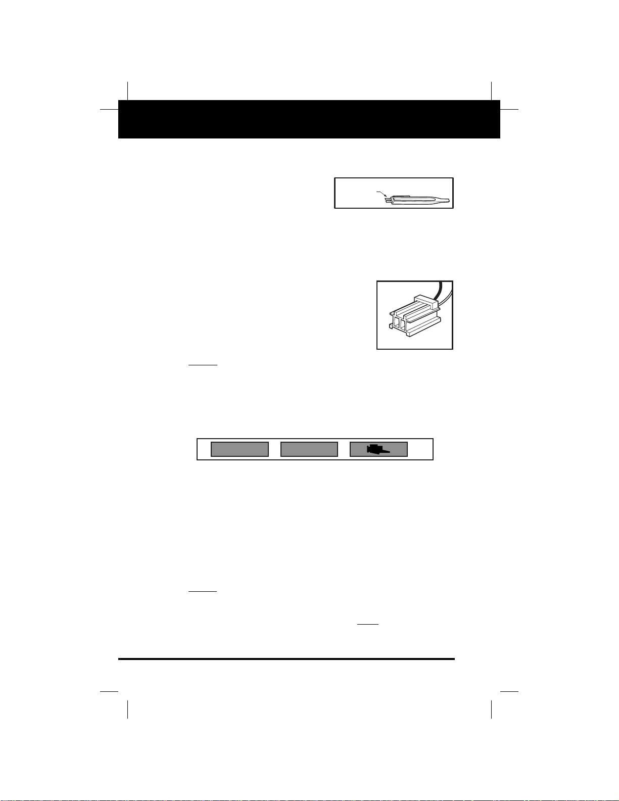
•
Retrieving codes from
Honda/Acura vehicles
requires the use of the two
terminal connector of code
retrieval tool as shown in Figure H1.
•
Honda/Acura vehicles use a variety of diagnostic systems
which use either the “Check Engine” light or LEDs (Light
Emitting Diodes) on the ECM (Engine Control Module) to
display diagnostic trouble codes.
•
To retrieve codes you will need to
access your vehicle’s computer test
connector or ECM.
•
Honda/Acura vehicles use a rectangular two-socket plastic connector,
usually light blue in color (H2).
NOTE:
Some Honda/Acura models do not require a tool to
retrieve codes. The “Tool Req?” column in the “Code Retrieval
Procedures Tables” on pages 14 through 17 will let you know if
a tool is required. If no tool is required, just follow the
procedures as indicated to retrieve codes.
“Check Engine” Light
•
The “Check Engine” light does more than alert you to a
potential problem. It also transmits the fault codes in the
computer’s memory through a series of blinks and pauses
when the vehicle is in diagnostic mode.
•
Your “Check Engine” light is located on your vehicle’s
instrument cluster, and may be labeled “PGM-FI”, “PGMCARB”, “CHECK”, or with a picture of an engine (Figure
H3).
NOTE:
If your “Check Engine” light does not come on when you
turn on the ignition, please refer to your vehicle’s service
manual. You may have a problem with the vehicle that is
preventing it from illuminating. You must fix this problem
before you can retrieve fault codes from the vehicle’s computer.
H1
H2
H3
HONDA
CONNECTOR
CHECK
CHECK ENGINE
Page 17
Honda/Acura
CODE RETRIEVAL PROCEDURE
Chapter 3 14
CODE RETRIEVAL PROCEDURE
•
Always observe safety precautions whenever working on a
vehicle.
•
Fix any known mechanical problems before this test.
•
Warm up engine before this test.
•
Have a pencil and paper handy.
1. Locate your vehicle in the appropriate table (see below for
“Honda Code Retrieval Procedures”; see page 16 for
“Acura Code Retrieval Procedures”).
2. Follow the procedures applicable to your vehicle.
■ Refer to page 18 for “ECU/Test Connector Locations”,
(Figures H4 through H9).
■ Refer to page 19 for “Code Examples” (Figures H10
through H17).
3. Refer to pages 21 and 22 for “Honda/Acura Fault Code
Definitions”. Match the retrieved Diagnostic Trouble Codes
with those listed, read the associated definition(s), and
consult the vehicle’s service manual for further evaluation.
4. Refer to page 20 for the “Erasing Codes” procedure.
Consult the appropriate table for your vehicle (“Honda
Erasing Procedure” or “Acura Erasing Procedure”) and
follow the procedure listed.
Honda Code Retrieval Procedures
Tool
Model Years Eng. Req? Perform the following:
Accord 84-85 1.8 (F.I. N Procedure: Access ECU (located
only) under driver’s seat) (H4). Turn ignition
on and observe LEDs on ECU for
codes.
Codes: Codes are displayed using 4
LEDs labeled 8, 4, 2, 1 (H10).
Determine codes by adding LED values.
Examples: LED 8 and LED 1 on =
code 9 (8 + 1 = 9) (H11)
LED 4 on = code 4 (4 + 0 = 4)
(H12)
No LEDs = code 0
(H13)
When more than one code is present,
codes are separated by a 2 second pause.
Page 18

Honda/Acura
CODE RETRIEVAL PROCEDURE
15 Chapter 3
Honda Code Retrieval Procedures (Cont)
Tool
Model Years Eng. Req? Perform the following:
Accord 86-89 2.0 (F.I. N Procedure: Access ECU (located under
only) front driver’s seat) (H4) by moving seat
all the way back. Turn ignition on and
observe LED on ECU for codes.
Codes: Codes blinked out by LED are
separated by two second pause, then
repeated. For example: 2 blinks - two
second pause - 2 blinks = code 2 (H14)
Accord 90 2.2 N Procedure: Access ECU (located on
Prelude 88-91 2.0, 2.1 passenger side floor board) (H6) by
pulling back the carpet. Turn ignition
on and observe LED on ECU for codes.
Codes: Codes 1 ~ 10 are displayed
using a series of short blinks (H15),
codes 11 & up use a combination of
long and short blinks (H16). The number of long blinks equals the first digit
and the number of short blinks equals
the second (H17).
Accord 91-95 2.2 (incl. Y Procedure: Access service check con-
V-TEC), nector (located under dashboard on
2.7 (incl. passenger side) (H7). Plug Code Reader
V-TEC) into service check connector and turn
Civic 92-95 1.5, 1.6 ignition on and observe “Check Engine”
Del Sol 94-95 1.5, 1.6 light for codes.
Odyssey 95 2.2, 2.3
Codes: Codes blink out one after the
other. “Check Engine” light will stop
blinking after all codes have been displayed. Trouble codes 1 - 10 are displayed using a series of short blinks
(H15); codes 11 & up use a combination of long and short blinks (H16).
The number of long blinks equals the
first digit and the number of short
blinks indicates the second (H17).
Civic/ 87-91 1.5, 1.6 N Procedure: Access ECU (located on
CRX passenger side floor board) (H6) by
pulling back the carpet. Turn ignition
on and observe LED on ECU for codes.
Codes: Codes blinked out by LED are
separated by two second pause, then
repeated. For example: 2 blinks - two
second pause - 2 blinks = code 2 (H14).
Page 19

Honda/Acura
CODE RETRIEVAL PROCEDURE
Chapter 3 16
Honda Code Retrieval Procedures (Cont)
Acura Code Retrieval Procedures
Tool
Model Years Eng. Req? Perform the following:
Prelude 85-87 1.8, 2.0 N Procedure: Access ECU (located be-
hind driver’s seat within door pillar assembly) (H8). Turn ignition on and
observe LED on ECU for codes.
Codes: Codes blinked out by LED are
separated by two second pause, then
repeated. For example: 2 blinks - two
second pause - 2 blinks = code 2 (H14)
Prelude 92-95 2.2, 2.3 Y Procedure: Access service check con-
nector (located behind center console on
driver’s side) (H9). Plug Code Reader
into service check connector and turn
ignition on. Observe “Check Engine”
light for codes.
Codes: Codes 1 - 10 are displayed
using a series of short blinks (H15),
codes 11 & up use a combination of
long and short blinks (H16). The number of long blinks equals the first digit
and the number of short blinks equals
the second (H17).
Tool
Model Years Eng. Req? Perform the following:
Integra 86-91 1.6, 1.8 N Procedure:
• All except 90, 91 models: Access
ECU (located under front passenger
seat) (H5) by moving seat all the
way back.
• 90, 91 models only: Access ECU
(located on passenger side floor board)
(H6) by pulling back the carpet.
• Turn ignition on and observe LED
on ECU for codes.
Codes: Codes blink out one after the
other. Trouble codes 1 - 10 are displayed using a series of short blinks
(H15), codes 11 and up use a combination of long and short blinks (H16).
The number of long blinks equals the
first digit and the number of short
equals the second (H17).
Page 20

Honda/Acura
CODE RETRIEVAL PROCEDURE
17 Chapter 3
Acura Code Retrieval Procedures (Cont)
Tool
Model Years Eng. Req? Perform the following:
Integra 92-95 1.7, 1.8 Y Procedure: Access service check conIntegra 94-95 1.8 nector (located under dashboard on pasV-TEC senger side) (H7). Plug Code Reader
Legend 91-95 2.5, 2.7, 3.2 into service check connector and turn
NSX 91-95 3.0, 3.2 ignition on. Observe “Check Engine”
Vigor 91-95 2.5 light for codes.
Codes: Codes blink out one after the
other. Trouble codes 1 - 10 are displayed using a series of short blinks
(H15), codes 11 and up use a combination of long and short blinks (H16).
The number of long blinks equals the
first digit and the number of short
equals the second (H17).
Legend 86-90 2.5, 2.7 N Procedure:
• 1986 models only: Access ECU
(located under front passenger seat
(H5) by moving seat all the way
back.
• 1987~89 models only: Access ECU
(located on passenger side floor
board) (H6) by pulling back carpet.
• Turn ignition on and observe LED
on ECU for codes.
Codes: Codes blink out in single
flashes followed by a two second pause
(For example, 2 blinks, then two second pause equals code 2 (H14). LED
will stop flashing after all codes have
been displayed.
Page 21

Honda/Acura
CODE RETRIEVAL PROCEDURE
Chapter 3 18
ECU/Test Connector Locations
The physical locations of the ECU or test connector for
Honda/Acura vehicles are shown in Figures H4 through H9.
Refer to the code retrieval instructions in Table H1 (Honda) or
Table H2 (Acura) to determine the correct location for your
vehicle.
H4
H5
H6
H7
H8
H9
Page 22

Honda/Acura
CODE RETRIEVAL PROCEDURE
19 Chapter 3
Code Examples
Examples of Honda/Acura fault codes are shown in Figures
H10 through H17. Refer to the code retrieval instructions in
Table H1 (Honda) or Table H2 (Acura) to determine the code
display for your vehicle.
H10
H12
H11
H13
H14
H15
H16
H17
8421
8421
LED 4
ON
BLINKBLINK
LONG BLINK
= Code 4
SHORT
BLINK BLINKBLINKBLINKBLINK
BLINK BLINK
BLINK
SHORT BLINK
SHORT
BLINKBLINK
LED 8
ON
PAUSE
2 SECONDS
PAUSE
3 - 4 SECONDS
8421
LED 1
ON
8421
ALL LEDs OFF
= CODE 2
= CODE 10
= Code 9
= Code 0
0.6 SEC.
LONG BLINK
LONG BLINK LONG BLINK
0.3 SEC.
SHORT
PAUSE
0.9 SECONDS
BLINKBLINK
SHORT
PAUSE
0.9 SECONDS
BLINK
LONG
PAUSE
2 SECONDS
LONG
PAUSE
2 SECONDS
= CODE 12 & 21
Page 23

Honda/Acura
ERASING CODES
Chapter 3 20
ERASING CODES
•
Always observe safety precautions whenever working on a
vehicle.
•
Remove Code Reader from vehicle’s test connector before
erasing codes.
•
Erase codes only when all repairs have been completed.
Refer to “Honda Erasing Procedures” or “Acura Erasing
Procedures” for specific instructions for your year, make
and model.
•
After erasing codes, verify that repairs were successfully
completed. Start the engine and warm to normal
operating temperature. After normal operating
temperature is reached, turn off the ignition and repeat
the code retrieval procedure for your vehicle. If no codes
are retrieved, the repair(s) was successful.
NOTE:
Removing fuses or battery cables may clear the memory
on the radio, clock, etc., or may enable the “Theftlock” feature
on the radio.
Honda Erasing Procedures
Acura Erasing Procedures
Model Years Procedure
Accord 84-85 Remove fuse No. 10 for 10 seconds
87-89 Remove fuse No. 11 for 10 seconds
90-93 Remove fuse No. 24 for 10 seconds
Civic / 94 Remove “Radio” fuse for 10 seconds
CRX
87-91 Remove fuse No. 30 for 10 seconds
Del Sol 92-95 Remove fuse No. 32 for 10 seconds
Odyssey 93-95 Remove “Radio” fuse for 10 seconds
Prelude 90 Remove “Radio” fuse for 10 seconds
89-91 Remove fuse No. 35 for 10 seconds
92-95 Remove fuse No. 43 for 10 seconds
Model Years Procedure
Integra 86-91 Remove “Hazard” fuse for 10 seconds
92-95 Remove “Back Up” fuse for 10 seconds
Legend 90 Remove “Alternator Sense” fuse for 10 seconds
91-95 Remove fuse No. 15 for 10 seconds
NSX 91-95 Remove “Clock” fuse for 10 seconds
Vigor 92-94 Remove “Back Up” fuse for 10 seconds
Page 24

Honda/Acura
FAULT CODE DEFINITIONS (0 - 20)
21 Chapter 3
HONDA/ACURA FAULT CODE DEFINITIONS
IMPORTANT:
Retrieving and utilizing Diagnostic Trouble
Codes (DTCs) for troubleshooting vehicle operation problems is
only one part of an overall diagnostic strategy. Never replace a
part based solely on the DTC definition. Always consult the
vehicle’s service manual for more detailed testing instructions.
Each DTC has a set of testing procedures, instructions and flow
charts that must be followed to confirm the exact location of the
problem. This type of information is found in the vehicle’s
service manual.
Code Description Possible Cause
0 ECU / ECU signal No signal to ECU
1 Oxygen sensor circuit Oxygen sensor or circuit, ECU
2 Oxygen sensor circuit Oxygen sensor or circuit, ECU
3 MAP sensor circuit Map sensor circuit
4 CKP sensor / engine speed (RPM) Crank angle sensor or circuit, ECU
sensor
5 MAP sensor circuit MAP sensor or circuit, mechanical
problem
6 ECT sensor circuit ECT sensor or circuit, automatic
transaxle control unit
7 TPS / Angle Sensor TPS sensor or circuit, automatic
transaxle control unit
8 CKP sensor / engine speed (RPM) Crank angle sensor or circuit, ECU
sensor
9 CMP sensor CMP sensor or circuit
10 IAT sensor IAT sensor or circuit
11 Idle Mixture Adjuster Sensor Idle mixture adjuster sensor or
circuit
12 EGR system fault No EGR action, faulty EGR valve
13 BARO sensor circuit BARO sensor or circuit
14 Idle Air Control valve circuit / ECU Open or shorted out ignition sig-
nal circuit / No signal to ECU
15 Ignition Output signal Open or shorted ignition output
signal circuit
16 Fuel Injector Circuit Open or shorted fuel injector
circuit
17 VSS circuit VSS sensor or circuit
18 Ignition Timing Adjuster Open or shorted signal circuit
19 A/T Lock-up control solenoid Open or shorted signal circuit,
Lock-up control solenoid lock-up solenoid
20 Electrical Load Detector / Sensor Electrical load detector or circuit
Page 25

Honda/Acura
Fault Code Definitions (21 - 59)
Chapter 3 22
Code Description Possible Cause
21 Spool Solenoid Valve Open or shorted signal circuit,
spool solenoid valve
22 Valve Timing Electronic Oil Open or shorted signal circuit,
pressure switch valve timing oil pressure switch
23 Knock sensor circuit Knock sensor or circuit
30 AT / ECU communication signal A AT control unit, ECU
31 AT / ECU communication signal B AT control unit, ECU
35 Traction control / ECU / signal Traction control module, ECU
36 Traction control / ECU / signal Traction control module, ECU
41 Oxygen sensor heater - left side Oxygen sensor / heater or circuit
42 Oxygen sensor heater - right side Oxygen sensor / heater or circuit
43 Fuel Supply system - left side Oxygen sensor or circuit, fuel
system
44 Fuel Supply system - right side Oxygen sensor or circuit, fuel
system
45 Fuel metering - left side Injector control circuit, incorrect
fuel metering
46 Fuel metering - right side Injector control circuit, incorrect
fuel metering
48 Heated oxygen sensor Oxygen sensor or circuit
53 Right Knock Sensor Right knock sensor or circuit
54 CKP sensor 2 CKP sensor 2 or circuit
59 CMP sensor 2 CMP sensor 2 or circuit
Page 26

Nissan/Infiniti
OVERVIEW OF NISSAN/INFINITI DIAGNOSTIC SYSTEMS
23 Chapter 4
OVERVIEW OF NISSAN/INFINITI DIAGNOSTIC SYSTEMS
•
Retrieving codes from
Nissan/Infiniti vehicles
requires the use of the flat
end of the code retrieval
tool shown in Figure N1.
•
Nissan/Infiniti vehicles use a variety of computer systems
which are equipped with either a single-LED (Light
Emitting Diode) or a dual-LED display.
•
To retrieve codes, you need to first locate the LED display on
the vehicle’s computer. The LED(s) are mounted inside the
computer, but may be seen by looking through an opening in
the top of or on the side of the computer housing. In some
cases you may have to remove the computer from its mount.
NOTE:
Refer to the vehicle’s service manual when removing the
computer from it’s mount, as it is easily damaged.
All Nissan/Infiniti vehicles
covered in this manual are
equipped with a screw-type
diagnostic mode selector on
the vehicle’s computer. The
diagnostic mode selector is
accessed through a cutout in
the computer housing. Two
marks show the operating
limits of the diagnostic mode
selector. The Code Reader is
used to adjust the position of
the diagnostic mode selector
(N2).
NOTE:
Some Nissan/Infiniti models do not require a tool to
retrieve codes. The “Tool Req?” column in the “Code Retrieval
Procedures Tables” on pages 24 through 29 will let you know if
a tool is required. If no tool is required, just follow the
procedures as indicated to retrieve codes.
N1
N2
NISSAN
TOOL
Page 27

Nissan/Infiniti
CODE RETRIEVAL PROCEDURE
Chapter 4 24
CODE RETRIEVAL PROCEDURE
•
Always observe safety precautions whenever working on a
vehicle.
•
Fix any known mechanical problems before this test.
•
Warm up engine before this test.
•
Have a pencil and paper handy.
1. Locate your vehicle in the appropriate table (see below for
“Nissan Code Retrieval Procedures”; see page 29 for
“Infiniti Code Retrieval Procedures”).
2. Follow the procedures applicable to your vehicle.
■ Refer to page 30 for “ECU Locations”, (Figures N3
through N7).
■ Refer to page 31 for “Code Examples” (Figures N8
through N11).
3. Refer to pages 34-36 for “Nissan/Infiniti Fault Code
Definitions”. Match the retrieved Diagnostic Trouble Codes
with those listed, read the associated definition(s), and
consult the vehicle’s service manual for further evaluation.
4. Refer to page 32 for the “Erasing Codes” procedure.
Consult the appropriate table for your vehicle (“Nissan
Erasing Procedure” or “Infiniti Erasing Procedure”) and
follow the procedure listed.
Nissan Code Retrieval Procedures
Tool
Model Years Eng. Req? Perform the following:
Altima 93-95 2.4 Y Procedure: Access ECU (located beMaxima 92-94 3.0 (DOHC) hind center console) (N3). Turn ignition
Sentra 91-95 2.0 on. Using Nissan tool, turn diagnostic
Stanza 90-92 2.4 mode selector fully clockwise; wait two
200SX 95 1.6, 2.0 seconds, then turn selector fully coun-
terclockwise. Observe red LED on
ECU for codes.
Codes: Codes are displayed using a
combination of long and short blinks.
Codes are determined by the number
and duration of blinks. A long blink indicates the first digit (ten); a short
blink indicates the second digit (ones)
(N8). Example: long blink-pause short
blink short blink = code 12 (N9). If
Page 28

Nissan/Infiniti
CODE RETRIEVAL PROCEDURE
25 Chapter 4
Nissan Code Retrieval Procedures (Cont)
Tool
Model Years Eng. Req? Perform the following:
Altima 93-95 2.4 Y more than one code is stored, the ECU
Maxima 92-94 3.0 (DOHC) will blink the lowest number code first,
Sentra 91-95 2.0 pause for two seconds, then display the
Stanza 90-92 2.4 next highest number code. This con200SX 95 1.6, 2.0 tinues until all stored codes have been
(cont) displayed; the cycle then repeats.
Stanza 86 2.0 Y Procedure: Access ECU (from driver’s
200SX 84-86 1.8, 2.0 side kick panel) (N6) (except Stanza
Wagon, which is located under driver’s
seat). Make sure diagnostic mode selector is turned fully counterclockwise.
Turn ignition on. Using Nissan tool,
turn selector fully clockwise. Observe
both red and green LEDs on ECU for
codes.
Codes: Codes are displayed by blinking
of both Red and Green LEDs (N10). The
Red LED blinks first, followed by the
Green LED. The Red LED indicates the
first digit (tens); the Green LED indicates the second digit (ones). Example:
one Red flash and two Green flashes =
code 12 (N11).
Pulsar 88-90 1.6, 1.8 Y Procedure:
Sentra 88-90 1.6 • All except 200 SX: Access ECU (loStanza 87-90 2.0, 2.4 cated under passenger seat) (N5)
200SX 87-88 2.0, 3.0 (except Stanza Wagon, which is lo-
cated under driver’s seat).
• 200 SX only: Access ECU (located
behind driver side kick panel) (N6).
• Turn ignition on. Using Nissan tool,
turn diagnostic mode selector fully
clockwise and observe LEDs on ECU.
When LEDs have flashed three times,
turn selector fully counterclockwise.
Observe both red and green LEDs
on ECU for codes.
Codes: Codes are displayed by blinking
of both Red and Green LEDs (N10). The
Red LED blinks first, followed by the
Green LED. The Red LED indicates the
first digit (tens); the Green LED indicates the second digit (ones). Example:
one Red flash and two Green flashes =
code 12 (N11).
Page 29

Nissan/Infiniti
CODE RETRIEVAL PROCEDURE
Chapter 4 26
Nissan Code Retrieval Procedures (Cont)
Tool
Model Years Eng. Req? Perform the following:
Maxima 86-94 3.0 (SOHC) Y Procedure:
• All except 87, 88 Maxima: Access
ECU (located under passenger seat)
(N5).
• 87, 88 Maxima only: Access ECU
(located behind center console) (N3).
• Turn ignition on. Using Nissan tool,
turn diagnostic mode selector fully
clockwise, wait at least two seconds,
then turn selector fully counterclockwise. Observe both red and green
LEDs on ECU for codes.
Codes: Codes are displayed by blinking
of both Red and Green LEDs (N10). The
Red LED blinks first, followed by the
green LED. The Red LED indicates the
first digit (tens); the Green LED indicates the second digit (ones). Example:
one Red flash and two Green flashes =
code 12 (N11).
NX 91-93 1.6, 2.0 Y Procedure: Access ECU (located be240SX 91-95 2.4 hind center console) (N3) (except 300ZX,
300ZX 90-95 3.0 (incl. which is located in passenger side foot-
Turbo) well under carpet (N5)). Turn ignition
on. Using Nissan tool, turn diagnostic
mode selector fully clockwise; wait two
seconds, then turn selector fully counterclockwise. Observe red LED on ECU
for codes.
Codes: Codes are displayed using a
combination of long and short blinks.
Codes are determined by the number
and duration of LED blinks. A long
blink indicates the first digit (tens); a
short pause indicates the second digit
(ones) (N8). Example: long blink-pauseshort blink short blink = code 12 (N9).
If more than one code is stored, the
ECU will blink the lowest number code
lowest number code first, pause for two
seconds, then display the next highest
number code. This continues until all
stored codes have been displayed; the
cycle then repeats.
Page 30

Nissan/Infiniti
CODE RETRIEVAL PROCEDURE
27 Chapter 4
Nissan Code Retrieval Procedures (Cont)
Tool
Model Years Eng. Req? Perform the following:
Van 87-88, 2.4 Y Procedure: Access ECU (located under
90 passenger seat) (N5). Using Nissan tool,
Pathfin- 87-95 2.4, 3.0 turn diagnostic mode selector fully
der clockwise and observe LEDs on ECU.
Hard- 87-95 2.4, 3.0 When LEDs have blinked three times,
body turn selector fully counterclockwise.
Pickup Observe both red and green LEDs on
ECU for codes.
Codes: Codes are displayed by blinking
of both Red and Green LEDs (N10). The
Red LED blinks first, followed by the
Green LED. The Red LED indicates the
first digit (tens); the Green LED indicates the second digit (ones). Example:
one Red flash and two Green flashes =
code 12 (N11).
240SX 89-90 2.4 Y Procedure: Access ECU (from passen-
ger side front kick panel) (N4), and position it so LEDs can be observed. Using
Nissan tool, turn diagnostic mode selector fully clockwise and observe LEDs on
ECU. When LEDs have blinked three
times, turn selector fully counterclockwise. Observe both red and green LEDs
on ECU for codes.
Codes: Codes are displayed by blinking
of both Red and Green LEDs (N10). The
Red LED blinks first, followed by the
Green LED. The Red LED indicates
the first digit (tens); the Green LED indicates the second digit (ones).
Example: one Red flash and two Green
flashes = code 12 (N11).
300ZX 86 3.0 (incl. Y Procedure: Access ECU (from passen-
Turbo) ger side front kick panel) (N4). Make
sure diagnostic mode selector is turned
fully counterclockwise. Turn ignition on.
Using Nissan tool, turn selector fully
clockwise. Observe both red and green
LEDs on ECU for codes.
Codes: Codes are displayed by blinking
of both Red and Green LEDs (N10). The
Red LED blinks first, followed by the
Green LED. The Red LED indicates the
first digit (tens); the Green LED indicates
Page 31

Nissan/Infiniti
CODE RETRIEVAL PROCEDURE
Chapter 4 28
Nissan Code Retrieval Procedures (Cont)
Tool
Model Years Eng. Req? Perform the following:
300ZX 86 3.0 Y the second digit (ones). Example: one
(cont) Red flash and two Green flashes = code
12 (N11).
300ZX 87-89 3.0 (incl. Y Procedure: Access ECU (from passen-
Turbo) ger side front kick panel) (N4). Turn ig-
nition on. Using Nissan tool, turn diagnostic mode selector fully clockwise and
observe LEDs on ECU. When LEDs
have blinked three times, turn selector
fully counterclockwise. Observe both
red and green LEDs on ECU for codes.
Codes: Codes are displayed by blinking
of both Red and Green LEDs (N10). The
Red LED blinks first, followed by the
Green LED. The Red LED indicates the
first digit (tens); the Green LED indicates the second digit (ones). Example:
one Red flash and two Green flashes =
code 12 (N11).
Axxess 90 2.4 Y Procedure: Access ECU (located be-
hind center console) (N3). Turn ignition
on. Using Nissan tool, turn diagnostic
mode selector fully clockwise and observe LEDs on ECU. When LEDs have
blinked three times, turn selector fully
counterclockwise. Observe both red
and green LEDs on ECU for codes.
Codes: Codes are displayed by blinking
of both Red and Green LEDs (N10). The
Red LED blinks first, followed by the
Green LED. The Red LED indicates the
first digit (tens); the Green LED indicates the second digit (ones). Example:
one Red flash and two Green flashes =
code 12 (N11).
Page 32

Nissan/Infiniti
CODE RETRIEVAL PROCEDURE
29 Chapter 4
Infiniti Code Retrieval Procedures
Tool
Model Years Eng. Req? Perform the following:
G20 91-95 2.0 Y Procedure: Access ECU (from pas-
senger side kick panel) (N4). Turn ignition on. Using Nissan tool, turn diagnostic mode selector fully clockwise;
wait for two seconds, then turn selector
fully counterclockwise. Observe LED on
ECU (or vehicle’s “Check Engine” light)
for codes.
Codes: Codes are displayed using both
long and short blinks (N8). The long
blinks represent the first digit, the
short blinks represent the second digit
(N9). Codes are displayed in numeric
order, beginning with the lowest number code and ending with the highest
number code.
J30 93-95 3.0 Y Procedure: Access ECU (from pasM30 90-92 3.0 senger side kick panel) (N4) and posiQ45 90-95 4.5 tion it to observe LED. Turn ignition
on. Using Nissan tool, turn diagnostic
mode selector fully clockwise, wait for
two seconds, then turn selector fully
counterclockwise. Observe LED on ECU
(or vehicle’s “Check Engine” light) for
codes.
Codes: Codes are displayed using both
long and short blinks (N8). The long
blinks represent the first digit, the
short blinks represent the second digit
(N9). Codes are displayed in numeric
order, beginning with the lowest number code and ending with the highest
number code.
Page 33

Nissan/Infiniti
CODE RETRIEVAL PROCEDURE
Chapter 4 30
ECU Locations
The physical locations of the ECU for Nissan/Infiniti vehicles
are shown in Figures N3 through N7. Refer to the code
retrieval instructions in Table N1 (Nissan) or Table N2 (Infiniti)
to determine the correct location for your vehicle.
N3
N4
N5 N6
N7
ECU may need to be
accessed from driver or
passenger side, depending
on model.
Page 34

Nissan/Infiniti
CODE RETRIEVAL PROCEDURE
31 Chapter 4
Code Examples
Examples of Nissan/Infiniti fault codes are shown in Figures
N8 through N11. Refer to the code retrieval instructions in
Table N1 (Nissan) or Table N2 (Infiniti) to determine the code
display for your vehicle.
N8
N9
N10
N11
GREEN
LED
SHORT BLINK
0.3 SEC.
SHORT
PAUSE
0.9 SECONDS
PAUSEPAUSE
RED
BLINK
LONG BLINK
0.6 SEC.
LONG BLINK
LONG BLINK LONG BLINK
RED
LED
RED
BLINK
RED
BLINK
GREEN
BLINK
PAUSE
BLINKBLINK
SHORT
PAUSE
0.9 SECONDS
GREEN
BLINK
GREEN
BLINK
BLINK
LONG
PAUSE
2 SECONDS
2 SECONDS
PAUSE
PAUSE
LONG
PAUSE
= CODE 12 & 21
= CODE 12 & 21
Page 35

Nissan/Infiniti
ERASING CODES
Chapter 4 32
ERASING CODES
•
Always observe safety precautions whenever working on a
vehicle.
•
Erase codes only when all repairs have been completed.
Refer to “Nissan Erasing Procedures” or “Infiniti Erasing
Procedures” for specific instructions for your year, make
and model.
•
After erasing codes, verify that repairs were successfully
completed. Start the engine and warm to normal
operating temperature. After normal operating
temperature is reached, turn off the ignition and repeat
the code retrieval procedure for your vehicle. If no codes
are retrieved, the repair(s) was successful.
Nissan Erasing Procedures
Model Years Procedure
Altima 93-95 After codes have been retrieved turn selector fully clockwise
and wait for two seconds. ECU code memory is now erased.
Axxess 90 After codes have been retrieved turn selector fully clockwise.
After the LED’s have blinked four times turn the selector
fully counterclockwise. ECU code memory is now erased.
Maxima 87-92 After codes have been retrieved turn selector fully clockwise
and wait for two seconds. ECU code memory is now erased.
93-94 After codes have been retrieved turn selector fully clockwise.
After the LED’s have blinked four times turn the selector
fully counterclockwise. ECU code memory is now erased.
NX 91-93 After codes have been retrieved turn selector fully clockwise
and wait for two seconds. ECU code memory is now erased.
Path- 87-95 After codes have been retrieved turn selector fully clockwise.
finder After the LED’s have blinked four times turn the selector
fully counterclockwise. ECU code memory is now erased.
Hard- 87-95 After codes have been retrieved turn selector fully clockwise.
body After the LED’s have blinked four times turn the selector
Pickup fully counterclockwise. ECU code memory is now erased.
Pulsar 88-90 After codes have been retrieved turn selector fully clockwise.
After the LED’s have blinked four times turn the selector
fully counterclockwise. ECU code memory is now erased.
Sentra 88-90 After codes have been retrieved turn selector fully clockwise.
After the LED’s have blinked four times turn the selector
fully counterclockwise. ECU code memory is now erased.
91-95 After codes have been retrieved turn selector fully clockwise
and wait for two seconds. ECU code memory is now erased.
Page 36

Nissan/Infiniti
ERASING CODES
33 Chapter 4
Nissan Erasing Procedures (Cont)
Infiniti Erasing Procedures
Model Years Procedure
Stanza 86 After codes have been retrieved turn selector fully clockwise
and wait for two seconds. ECU code memory is now erased.
87-89 After codes have been retrieved turn selector fully clockwise.
After the LED’s have blinked four times turn the selector
fully counterclockwise. ECU code memory is now erased.
91-92 After codes have been retrieved turn selector fully clockwise
and wait for two seconds. ECU code memory is now erased.
Van 87-90 After codes have been retrieved turn selector fully clockwise.
After the LED’s have blinked four times turn the selector
fully counterclockwise. ECU code memory is now erased.
200SX 84-86 After codes have been retrieved turn selector fully clockwise
and wait for two seconds. ECU code memory is now erased.
87-88 After codes have been retrieved turn selector fully clockwise.
After the LED’s have blinked four times turn the selector
fully counterclockwise. ECU code memory is now erased.
90 After codes have been retrieved turn selector fully clockwise
and wait for two seconds. ECU code memory is now erased.
240SX 89-90 After codes have been retrieved turn selector fully clockwise.
After the LED’s have blinked four times turn the selector
fully counterclockwise. ECU code memory is now erased.
91-95 After codes have been retrieved turn selector fully clockwise
and wait for two seconds. ECU code memory is now erased.
300ZX 86 After codes have been retrieved turn selector fully clockwise
and wait for two seconds. ECU code memory is now erased.
87-89 After codes have been retrieved turn selector fully clockwise.
After the LED’s have blinked four times turn the selector
fully counterclockwise. ECU code memory is now erased.
90-95 After codes have been retrieved turn selector fully clockwise
and wait for two seconds. ECU code memory is now erased.
Model Years Procedure
All All After you have finished retrieving codes turn the selector
back fully clockwise to erase the ECU code memory.
Page 37

Nissan/Infiniti
FAULT CODE DEFINITIONS (11 - 51)
Chapter 4 34
NISSAN/INFINITI FAULT CODE DEFINITIONS
IMPORTANT:
Retrieving and utilizing Diagnostic Trouble
Codes (DTCs) for troubleshooting vehicle operation problems is
only one part of an overall diagnostic strategy. Never replace a
part based solely on the DTC definition. Always consult the
vehicle’s service manual for more detailed testing instructions.
Each DTC has a set of testing procedures, instructions and flow
charts that must be followed to confirm the exact location of the
problem. This type of information is found in the vehicle’s
service manual.
Code Description Possible Cause
11 CKP sensor circuit CKP sensor or circuit
12 MAF sensor circuit MAF sensor or circuit, MAF signal
too high
13 ECT sensor circuit ECT sensor or circuit
14 VSS circuit VSS or circuit
16 Traction Control System Open or shorted signal circuit
21 No ignition reference pulse Loss of primary signal
22 Fuel Pump / Idle speed control valve Open or shorted signal circuit
23 Idle switch / throttle valve switch Open or shorted signal circuit /
defective idle speed valve
24 Idle switch / Trans. switch / Open or shorted signal circuit
Neutral/Park switch
25 Idle Speed control Open or shorted AAC circuit
31 ECU circuit Abnormal input signals
32 EGR sensor circuit No EGR operation
33 HO2S fault Open or shorted signal circuit,
high HO2S signal
34 Knock Sensor circuit Knock sensor or circuit
35 EGR temperature sensor EGR temperature sensor or circuit
36 EGR valve / system EGR / EVAP valve or circuit
37 Closed loop control HO2S, intake/fuel system
41 Air temperature sensor Air temperature sensor or circuit
42 Fuel temperature sensor Fuel temperature sensor or circuit
43 TPS circuit TPS or circuit
44 No faults / no malfunctions
45 Injector leak Leak at injector
46 Secondary TPS circuit Secondary TPS or circuit
51 Injector circuit Defective injector
Page 38

Nissan/Infiniti
FAULT CODE DEFINITIONS (53 - 111)
35 Chapter 4
Code Description Possible Cause
53 Oxygen sensor - right side Open or shorted signal circuit,
high O2 signal
54 A/T signal Open signal in trans. Control unit
55 No faults / no malfunctions
63 No. 6 cylinder misfire Wiring, fuel or ignition system,
ECM
64 No. 5 cylinder misfire Wiring, fuel or ignition system,
ECM
65 No. 4 cylinder misfire Wiring, fuel or ignition system,
ECM
66 No. 3 cylinder misfire Wiring, fuel or ignition system,
ECM
67 No. 2 cylinder misfire Wiring, fuel or ignition system,
ECM
68 No. 1 cylinder misfire Wiring, fuel or ignition system,
ECM
71 Random misfire Wiring, fuel or ignition system,
ECM
72 TWC function RH bank Catalytic converter, wiring, ECM
73 TWC function LH bank Catalytic converter, wiring, ECM
76 Fuel injection system function RH Wiring, injector, oxygen sensor
bank
77 Rear HO2S circuit Wiring, injector, oxygen sensor
82 CKP sensor Wiring, CKP sensor, ECM
84 A/T diagnosis communication line Wiring, ECM
85 CMP actuator - circuit malfunction Wiring, CMP sensor, ECM
86 Fuel injection system function LH Wiring, oxygen sensor, MAF, ECM
bank
87 Canister control solenoid valve Wiring, EVAP valve, ECM
circuit
91 Front HO2S heater circuit RH bank Wiring, HO2S, ECM
94 TCC solenoid valve Wiring, clutch solenoid, ECM
95 CKP sensor Wiring, CKP sensor, ECM
98 ECT sensor Wiring, ECT sensor, ECM
101 Front HO2S heater circuit LH bank Wiring HO2S, ECM
101 CMP sensor circuit CMP sensor or circuit
102 MAF sensor circuit MAF sensor or circuit
103 ECT sensor circuit ECT sensor or circuit
104 VSS circuit malfunction VSS or circuit
111 EVAP canister purge control system EVAP valve
Page 39

Nissan/Infiniti
FAULT CODE DEFINITIONS (113 - 115)
Chapter 4 36
Code Description Possible Cause
113 EVAP canister purge control system EVAP valve
114 Fuel trim - right side - fuel too rich Oxygen sensor or circuit, fuel
pressure
115 Fuel trim - right side - fuel too rich Oxygen sensor or circuit, fuel
pressure
Page 40

Toyota/Lexus
OVERVIEW OF TOYOTA/LEXUS DIAGNOSTIC SYSTEMS
37 Chapter 5
OVERVIEW OF TOYOTA/LEXUS DIAGNOSTIC SYSTEMS
•
Retrieving codes from Toyota/Lexus
vehicles requires connecting either the
round or square end of code retrieval
tool (Figure T1) to vehicle’s test
connector.
•
To retrieve codes, you will need to access
your vehicle’s computer test connector.
Round Connector (T2): Used on older model
cars and vans. Yellow or green in color,
located under the hood.
•
Front corner (right or left)
•
Fender well (right or left)
•
Fire wall (right or left)
It may have a protective cap or may be plugged into a
protective cap mounted on the side wall. Use round head of
Code Reader on vehicles with this type of connector.
Square Connector (T3): Used on newer
model cars and vans. Black or grey in color
located under the hood near either:
•
Front corner (right or left)
•
Fender well (right or left)
•
Fire wall (right or left)
It has a cover labeled “DIAGNOSTIC”, “DIAGNOSIS”, or
“CHECK CONN”. Use square head of Code Reader on vehicles
with this type of connector.
NOTE:
Some Toyota/Lexus models do not require a tool to
retrieve codes. The “Tool Req?” column in the “Code Retrieval
Procedures Tables” on pages 38 through 41 will let you know if
a tool is required. If no tool is required, just follow the
procedures as indicated to retrieve codes.
“Check Engine” Light
•
Transmits the fault codes in the computer’s memory to
you.
T1
T3
T2
Page 41

Toyota/Lexus
CODE RETRIEVAL PROCEDURE
Chapter 5 38
CODE RETRIEVAL PROCEDURE
•
Always observe safety precautions whenever working on a
vehicle.
•
Fix any known mechanical problems before this test.
•
Warm up engine before this test.
•
Have a pencil and paper handy.
1. Locate your vehicle in the appropriate table (see below for
“Toyota Code Retrieval Procedures”; see page 40 for
“Lexus Code Retrieval Procedures”).
2. Follow the procedures applicable to your vehicle.
■ Refer to page 41 for “Diagnostic Connector Locatons”,
(Figures T6 and T7).
■ Refer to page 42 for “Code Examples” (Figures T8
through T10).
3. Refer to pages 45-47 for “Toyota/Lexus Fault Code
Definitions”. Match the retrieved Diagnostic Trouble Codes
with those listed, read the associated definition(s), and
consult the vehicle’s service manual for further evaluation.
4. Refer to page 43 for the “Erasing Codes” procedure.
Consult the appropriate table for your vehicle (“Toyota
Erasing Procedures” or “Lexus Erasing Procedures”) and
follow the procedure listed.
Toyota Code Retrieval Procedures
Tool
Model Years Eng. Req? Perform the following:
Corolla 85-86 1.6 Y Procedure: Locate round diagnostic
Pickup 85-86 2.4 connector (under hood) (T6). Plug Code
Supra 84-86 2.8 Reader into diagnostic connector. Turn
4 Runner 84-86 2.4 ignition on. Observe “Check Engine”
Van 84-89 2.0, 2.2 light for codes.
Codes: If there are no codes stored in
memory, the “Check Engine” light will
blink once every three seconds. If codes
are stored, the light will blink a number
of times equal to the code number every
three seconds. Example: Three blinks =
code 3 (T8). If more than one code is
stored, the lowest number code is displayed first, followed by a three second
pause, then the next highest number
code. Codes will continue to cycle (repeat) as long as the ignition is on and
the Code Reader is connected.
Page 42

Toyota/Lexus
CODE RETRIEVAL PROCEDURE
39 Chapter 5
Toyota Code Retrieval Procedures (Cont)
Tool
Model Years Eng. Req? Perform the following:
Camry 85-93 2.0, 2.2, 2.5 Y Procedure: Locate rectangular diag-
Celica 86-95 1.6, 1.8, nostic connector (under hood) (T7). Plug
2.0, 2.2 Code Reader into diagnostic connector.
Corolla 89-95 1.6, 1.8 Turn ignition on. Observe “Check
Engine” light for codes.
Codes: Codes are displayed using a
series of blinks and pauses. Example:
blink-pause-blink, blink, blink = code 13
(T9). If more than one code is stored,
the lowest number code is displayed
first, followed by a 2.5 second pause,
then the next highest number code.
When all codes have been displayed,
there is a 4.5 second pause, then the
codes are repeated. Codes will continue
to cycle as long as the ignition is on
and the Code Reader is connected.
Cressida 83-89 All w/ N Procedure: Locate “Super Monitor Dis-
Supra 87-88 “Super play” on dashboard (T5). Push and hold
Monitor the SELECT and INPUT M keys simulDisplay” taneously for four seconds. DIAG will
appear on the screen. Push and hold
SET key for four seconds. View codes on
LCD display.
Codes: The screen will show OK of no
codes are present (T10). If codes are
present they will appear on the screen
screen (T10). If more than one code is
present, they will be separated by a
three second pause.
Cressida 87-92 2.8, 3.0 Y Procedure: Locate rectangular diagLand 88-94 4.0, 4.5 nostic connector (under hood) (T7). Plug
Cruiser Code Reader into diagnostic connector.
Paseo 92-95 1.5 Turn ignition on. Observe “Check
Pickup 87-95 2.4, 3.0 Engine” light for codes.
(Fl only)
Codes: If there are no codes stored in
Previa 91-95 2.4 (exc. SC)
memory, the “Check Engine” light will
Supra 87-95 3.0
blink about two times per second. If
T100 93-94 3.0
codes are stored, codes are displayed
Tercel 89-94 1.5 using a series of blinks and pauses.
4 Runner 87-95 2.4, 3.0 Example: blink-pause-blink blink
blink = code 13 (T9). If more than one
code is stored, codes are separated by
a 2.5 second pause. When all codes have
been displayed, there is a 4.5 second
pause, then the codes are repeated.
Page 43

Toyota/Lexus
CODE RETRIEVAL PROCEDURE
Chapter 5 40
Toyota Code Retrieval Procedures (Cont)
Lexus Code Retrieval Procedures
Tool
Model Years Eng. Req? Perform the following:
Cressida 87-92 2.8, 3.0 Y Codes will continue to cycle as long as
Land 88-94 4.0, 4.5 the ignition is on and the Code Reader
Cruiser is connected.
Paseo 92-95 1.5
Pickup 87-95 2.4, 3.0
(Fl only)
Previa 91-95 2.4 (exc. SC)
Supra 87-95 3.0
T100 93-94 3.0
Tercel 89-94 1.5
4 Runner 87-95 2.4, 3.0
(cont)
MR2 85-89 1.6 Y Procedure: Locate rectangular diag-
91-95 2.0, 2.2 nostic connector (under hood) (T7). Plug
Code Reader into diagnostic connector.
Turn ignition on. Observe “Check
Engine” light for codes.
Codes: If there are no codes stored in
memory, the “Check Engine” light will
blink once every six seconds on 85-88
models, and about two times per second
on 89-95 models. If codes are stored,
codes are displayed using a series of
blinks and pauses. Example: blinkpause-blink blink blink = code 13 (T9).
If more than one code is stored, codes
are separated by a 2.5 second pause.
When all codes have been displayed,
there is a 4.5 second pause, then the
codes are repeated. Codes will continue
to cycle as long as the ignition is on and
the Code Reader is connected.
Tool
Model Years Eng. Req? Perform the following:
ES350 90-91 2.5 Y Procedure: Locate rectangular diagES300 92-93 3.0 nostic connector (under hood) (T7). Plug
GS300 93-95 3.0 Code Reader into diagnostic connector.
LS400 90-94 4.0 Turn ignition on. Observe “Check
SC300 92-95 3.0 Engine” light for codes.
SC400 92-95 4.0
Page 44

Toyota/Lexus
CODE RETRIEVAL PROCEDURE
41 Chapter 5
Lexus Code Retrieval Procedures (Cont)
Diagnostic Connector Locations
The physical locations of diagnostic connectors for Toyota /
Lexus vehicles are shown in Figures T5 through T7. Refer to
the code retrieval instructions in Table T1 (Toyota) or Table T2
(Lexus) to determine the correct location for your vehicle.
Tool
Model Years Eng. Req? Perform the following:
ES350 90-91 2.5 Y Codes: Codes are displayed using a
ES300 92-93 3.0 series of blinks and pauses. Example:
GS300 93-95 3.0 blink pause blink, blink, blink = code 13
LS400 90-94 4.0 (T9). If more than one code is stored,
SC300 92-95 3.0 codes are separated by a 2.5 second
SC400 92-95 4.0 pause. When all codes have been dis(cont) played, there is a 4.5 second pause, then
the codes are repeated. Codes will continue to cycle as long as the ignition is
on and the Code Reader is connected.
T5
T6
T7
HM
SELECT INPUT SET
SUPER MONITOR
Page 45

Toyota/Lexus
CODE RETRIEVAL PROCEDURE
Chapter 5 42
Code Examples
Examples of Toyota/Lexus fault codes are shown in Figures
T8 through T10. Refer to the code retrieval instructions in
Table T1 (Toyota) or Table T2 (Lexus) to determine the code
display for your vehicle.
T8
T9
T10
BLINKBLINK
BLINK
SHORT
PAUSE
BLINK
BLINK
BLINK
BLINK
SELECT INPUT SET
HM
SUPER MONITOR
PAUSE
3 - 4 SECONDS
PAUSE
3 - 4 SECONDS
or
= CODE 3
= CODE 13
SELECT INPUT SET
HM
SUPER MONITOR
Page 46

Toyota/Lexus
ERASING CODES
43 Chapter 5
ERASING CODES
•
Always observe safety precautions whenever working on a
vehicle.
•
Remove Code Reader from vehicle’s test connector before
erasing codes.
•
Erase codes only when all repairs have been completed.
Refer to “Toyota Erasing Procedures” or “Lexus Erasing
Procedures” for specific instructions for your year, make
and model.
•
After erasing codes, verify that repairs were successfully
completed. Start the engine and warm to normal
operating temperature. After normal operating
temperature is reached, turn off the ignition and repeat
the code retrieval procedure for your vehicle. If no codes
are retrieved, the repair(s) was successful.
NOTE:
Removing fuses or battery cables may clear the memory
on the radio, clock, etc., or may enable the “Theftlock” feature
on the radio.
Toyota Erasing Procedures
Model Years Procedure
4 Runner 85-94 With ignition off, remove 15A “EFI’ fuse for 30 seconds.
Camry 85 With ignition off, remove negative battery cable for 30
conds.
86 With ignition off, remove 15A “ECU-B” fuse for 30 seconds.
87-93 With ignition off, remove 15A “EFI” fuse for 30 seconds.
Celica 86-95 With ignition off, remove 15A “EFI” fuse for 30 seconds.
Corolla 87-91 With ignition off, remove 15A “Stop” fuse for 30 seconds.
92-95 With ignition off, remove 15A “EFI” fuse for 30 seconds.
Cressida 83-89 With Super Monitor Display: With ignition off, remove
15A “EFI” fuse for 30 seconds.
87-88 With ignition off, remove 15A “EFI” fuse for 30 seconds.
89-92 With ignition off, remove 20A “EFI” fuse for 30 seconds.
MR2 85-87 With ignition off, remove 7.5A “AM2” fuse for 30 seconds.
88-95 With ignition off, remove 15A “EFI” fuse for 30 seconds.
Land 88-94 With ignition off, remove 15A “EFI” fuse for 30 seconds.
Cruiser
Paseo 92-95 With ignition off, remove 15A “EFI” fuse for 30 seconds.
Page 47

Toyota/Lexus
ERASING CODES
Chapter 5 44
Toyota Erasing Procedures (Cont)
Lexus Erasing Produres
Model Years Procedure
Pickup 85-88 With ignition off, remove 15A “EFI” fuse for 30 seconds.
89 With ignition off, remove 15A “Haz-Horn” fuse for 30
seconds.
90-94 With ignition off, remove 15A “EFI” fuse for 30 seconds.
Previa 91-95 With ignition off, remove 15A “EFI” fuse for 30 seconds.
Supra 87-88 With Super Monitor Display: With ignition off, remove
15A “EFI” fuse for 30 seconds.
85-86 With ignition off, remove 15A “Stop” fuse for 30 seconds.
87-92 With ignition off, remove 15A “EFI” fuse for 30 seconds.
94-95 With ignition off, remove 30A “EFI” fuse for 30 seconds.
T100 93 With ignition off, remove 15A “EFI” fuse for 30 seconds.
Tercel 89-90 With ignition off, remove 20A “Stop” fuse for 30 seconds.
91-94 With ignition off, remove 15A “EFI” fuse for 30 seconds.
Van 84-89 With ignition off, remove 15A “EFI” fuse for 30 seconds.
Model Years Procedure
ES250 90-91 With ignition off, remove the 20A “EFI” fuse for 10 seconds.
ES300 92-93 With ignition off, remove the 15A “EFI” fuse for 10 seconds.
GS300 93-95 With ignition off, remove the 20A “EFI” fuse for 10 seconds.
LS400 90-94 With ignition off, remove the 20A “EFI” fuse for 10 seconds.
SC300 92-93 With ignition off, remove the 30A “EFI” fuse for 10 seconds.
94-95 With ignition off, remove the 20A “EFI” fuse for 10 seconds.
SC400 92-95 With ignition off, remove the 30A “EFI” fuse for 10 seconds.
Page 48

Toyota/Lexus
FAULT CODE DEFINITIONS (1 - 16)
45 Chapter 5
TOYOTA/LEXUS FAULT CODE DEFINITIONS
IMPORTANT:
Retrieving and utilizing Diagnostic Trouble
Codes (DTCs) for troubleshooting vehicle operation problems is
only one part of an overall diagnostic strategy. Never replace a
part based solely on the DTC definition. Always consult the
vehicle’s service manual for more detailed testing instructions.
Each DTC has a set of testing procedures, instructions and flow
charts that must be followed to confirm the exact location of the
problem. This type of information is found in the vehicle’s
service manual.
Code Description Possible Cause
1 System Normal
2 VAF sensor circuit VAF circuit, ECU
3 No ignition signal Ignition or circuit, coil, ECU
4 ECT sensor circuit ECT sensor or circuit, ECU
5 O2S circuit O2S sensor or circuit, ECU
6 Engine Speed (RPM) sensor circuit Ignitor or circuit, distributor, ECU
7 TPS circuit TPS or circuit, ECU
8 IAT sensor circuit IAT sensor or circuit, ECU
9 VSS circuit VSS sensor or circuit, ECU
10 Starter signal circuit VSS sensor or circuit, main relay
or circuit, ignition circuit, starter
circuit, ECU
11 ECU Power Supply Ignition or circuit, coil, ECU
11 A/C switch ON during code retrieval A/C switch, ECU
11 Closed throttle position switch Throttle position switch or circuit,
OFF during code retrieval ECU
11 Park / Neutral position switch in Park / Neutral switch, start
D during code retrieval switch, ECU
12 Engine Speed (RPM) sensor Distributor or circuit, ignitor or
circuit circuit, starter or circuit, ECU
(non-turbo models); crankshaft
or position sensor / circuit, starter
or circuit, ECU (turbo models)
13 Engine Speed (RPM) sensor above Distributor or circuit, ignitor or
1000 RPM circuit, starter or circuit, ECU
(non-turbo models); crankshaft or
position sensor / circuit, starter or
circuit, ECU (turbo models)
14 Ignition reference no signal Ignition coil, ignitor or circuit, ECU
14 Turbocharger pressure Turbocharger, airflow meter, ECU
16 Transmission control signal Transaxle ECU or circuit, ECU
Page 49

Toyota/Lexus
FAULT CODE DEFINITIONS (21 - 51)
Chapter 5 46
Code Description Possible Cause
21 HO2S front circuit HO2S sensor / heater or circuit,
ECU
22 ECT sensor circuit ECT sensor or circuit, ECU
23 IAT sensor circuit IAT sensor or circuit, ECU
24 IAT sensor circuit IAT sensor or circuit, ECU
25 Mixture control continuously lean Loose ground, injector or circuit,
oxygen sensor or circuit, fuel pres-
sure, ignition system coolant tem-
perature sensor, air intake system,
airflow meter, air leak, ignition
system, electronic air bleed control
valve, MAP sensor, vacuum sensor,
ECU
26 Mixture control continuously rich Loose ground, injector or circuit,
oxygen sensor or circuit, fuel pres-
sure, ignition system coolant tem-
perature sensor, air intake system,
airflow meter, air leak, ignition
system, electronic air bleed control
valve, MAP sensor, vacuum sensor,
ECU
27 HO2S rear circuit Oxygen sensor or circuit, ECU
28 HO2S right hand front circuit HO2S sensor / heater or circuit,
ECU
31 VAF sensor circuit VAF circuit, ECU
32 VAF sensor circuit VAF circuit, ECU
34 Turbocharger wastegate pressure Turbocharger pressure sensor or
too high circuit, turbocharger, MAP sensor,
airflow meter, wastegate VSV or
circuit, ECU
35 Turbocharger wastegate pressure Turbocharger pressure sensor or
sensor circuit / BARO circuit, MAP sensor or circuit, ECU
41 TPS circuit TPS sensor or circuit, ECU
42 VSS circuit VSS sensor or circuit, slipping
torque converter, ECU
43 Starter signal circuit Starter signal circuit, main relay,
starter relay, ignition switch or
circuit, ECU
47 Sub-Throttle position sensor signal Sub-TPS sensor or circuit, ECU
51 A/C switch ON during code Throttle position switch or circuit,
retrieval ECU
51 Closed throttle position switch Throttle position switch or circuit,
OFF during code retrieval ECU
Page 50

Toyota/Lexus
FAULT CODE DEFINITIONS (51 - 85)
47 Chapter 5
Code Description Possible Cause
51 Park / Neutral position switch not Park / Neutral switch, start switch,
in P or N during code retrieval ECU
52 Knock Sensor circuit Knock sensor or circuit, ECU
53 Knock control malfunction Knock sensor or circuit, ECU
54 Turbocharger intercooler control - Intercooler, coolant level sensor or
coolant too low circuit, intercooler water pump or
circuit, intercooler ECU, ECU
54 Turbocharger intercooler control - Intercooler, coolant level sensor or
coolant pump motor circuit, intercooler water pump or
circuit, intercooler ECU, ECU
55 Knock sensor right hand circuit Knock sensor or circuit, ECU
71 EGR system malfunction EGR system, EGR temperature
sensor or circuit, EGR BVSV or
VSV or circuit, ECU
72 Fuel cut-off solenoid signal Fuel cut-off solenoid or circuit, ECU
78 Fuel pump control signal Fuel pump or circuit, ECU power
source or ECU
81 Transmission Control Module ECT1
Communication
83 Transmission Control Module ESA1
Communication
84 Transmission Control Module ESA2
Communication
85 Transmission Control Module ESA3
Communication
Page 51

Toyota/Lexus
Chapter 5 48
Page 52

Glossary
49 Chapter 6
INTRODUCTION
This Glossary contains definitions for abbreviations and terms
you may find in this manual or in your vehicle service manual.
GLOSSARY OF TERMS AND ABBREVIATIONS
A/C – Air Conditioning
A/T – Automatic Transmission
AAC – Auxiliary Air Control
BARO – Barometric Pressure
CKP – Crankshaft Position
CMP – Camshaft Position
CTP – Closed Throttle Position
DOHC – Dual Overhead Cam
ECT – Engine Coolant Temperature
ECM / ECU – Engine Control Module / Unit (vehicle’s computer)
EFI – Electronic Fuel Injection
EGR – Exhaust Gas Recirculation
EVAP – Evaporative Emissions Control
F.I. – Fuel Injection
HO2S – Heated Oxygen Sensor
IAT – Intake Air Temperature
L/H – Left Hand
LED – Light Emitting Diode
M/T – Manual Transmission
MAF – Mass Air Flow
MAP – Manifold Absolute Pressure
O2S – Oxygen Sensor
OBD I – On Board Diagnostics First Generation
R/H – Right Hand
SOHC – Single Overhead Cam
TCM – Transmission Control Module
TPS – Throttle Position Sensor
VAF – Vane Air Flow
VSS – Vehicle Speed Sensor
Page 53

Glossary
Chapter 6 50
Page 54

Warranty and Service
51 Chapter 7
LIMITED ONE YEAR WARRANTY
The Manufacturer warrants to the original purchaser that this
unit is free of defects in materials and workmanship for a
period of one (1) year from the date of original purchase. If the
unit fails within the one (1) year period, it will be repaired or
replaced, at the Manufacturer's option, at no charge, when
returned prepaid to the Technical Service Center with Proof of
Purchase. The sales receipt may be used for this purpose.
Installation labor is not covered under this warranty.
All replacement parts, whether new or re-manufactured,
assume as their warranty period for only the remaining time
of this warranty. This warranty does not apply to damage
caused by improper use, accident, abuse, or if the product was
altered or repaired by anyone other than the Manufacturer's
Technical Service Center. Consequential and incidental
damages are not recoverable under this warranty. Some states
do not allow the exclusion or limitation of incidental or
consequential damages, so the above limitation or exclusion
may not apply to you.
This warranty gives you specific legal rights, and you may also
have other rights, which vary from state to state. No portion of
this warranty may be copied or duplicated without the
expressed written permission from the Manufacturer.
TECHNICAL ASSISTANCE AND WARRANTY SERVICE
Products requiring service should be returned as follows:
1. Call the Technical Service Center to obtain a Return
Reference Number:
2. Package the product carefully to prevent shipping damage
3. Include your name, return address, and a day contact
phone
4. Enclose a copy of the dated sales receipt
5. Describe the problem
6. Ship prepaid to: Technical Service Center, 17291 Mt.
Herrmann Street, Fountain Valley, CA 92708 U.S.A.
For Technical Assistance/Warranty Service, contact us at:
Phone: USA & Canada 1-800-544-4124, Others
714-241-6805; Fax: 714-432-7910; Web: www.iEquus.com;
Email: service@iEquus.com
Page 55

Warranty and Service
Chapter 7 52
Page 56

#3173
IMPORT COMPUTER
CODE READER
(BACK COVER)
 Loading...