

Page 1
September 2011 Ed.2.0
EQUITEL – Technical Manual N968
User manual
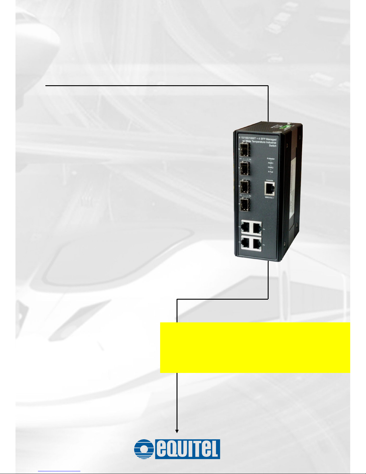
Managed industrial switch
N968
Page 2

September 2011 Ed.2.0
EQUITEL – Technical Manual N968
About this manual …
This document is the technical reference of the model N968, an 4
10/100/1000TX + 4 100/1000T/SFP modules combo -Managed Industrial Switch-
.
© Equipos De Telecomunicación Optoelectrónicos, S.A.
Zaragoza, Spain, Sep. 2011
Ed. 2.0
Equipos de Telecomunicación Optoelectrónicos, S.A.
Polígono de Malpica, c/ F oeste, G. Quejido, nave 74
50057 Zaragoza SPAIN
Tel. +34 976 570 353
Fax +34 976 571 383
E-mail: [email protected]
www.equitel.es
The information included in this manual cannot be copied or reproduced in any way without the previous written
authorisation of Equipos de Telecomunicación Optoelectrónicos, S.A.
Page 3

September 2011 Ed.2.0
EQUITEL – Technical Manual N968
Content
Overview............................................................1
Introduction .............................................................. 1
Features................................................................... 3
Technical Specifications........................................... 4
Packing List.............................................................. 7
Safety Precaution..................................................... 7
Hardware Description.........................................8
Physical Dimensions................................................ 8
LED Indicators.......................................................... 9
Installation........................................................10
RJ-45 Cabling ........................................................ 10
SFP Cabling........................................................... 13
Grounding the Industrial Switch ............................. 16
Wiring the Power Inputs......................................... 17
Wiring the P-Fail Alarm Contacts........................... 19
DIN-Rail Mounting.................................................. 20
Page 4

September 2011 Ed.2.0
EQUITEL – Technical Manual N968
Wall Mounting ........................................................ 22
Installation Steps.................................................... 23
Configuration....................................................24
RS-232 Console..................................................... 24
Pin Assignments ............................................................. 24
Login in the Console Interface.........................................25
SSH........................................................................ 27
Configuring PuTTY..........................................................27
Web-Based Management ......................................32
SSL.................................................................................33
System Information......................................................... 35
IP Configuration .............................................................. 36
DHCP Server..................................................................39
TFTP...............................................................................43
System Event Log........................................................... 46
Fault Relay Alarm............................................................ 52
SNTP Configuration........................................................ 53
IP Security.......................................................................57
User Authentication......................................................... 59
Port Statistics..................................................................60
Page 5

September 2011 Ed.2.0
EQUITEL – Technical Manual N968
Port Control.....................................................................62
Port Trunk.......................................................................64
Port Mirroring..................................................................73
Rate Limiting...................................................................74
DMI.................................................................................75
VLAN Configuration ........................................................ 77
Rapid Spanning Tree...................................................... 87
SNMP Configuration ....................................................... 92
QoS Configuration...........................................................98
X-Ring2.........................................................................101
LLDP Configuration.......................................................104
802.1X/Radius...............................................................105
MAC Address Table...................................................... 109
IGMP/MLD Snooping.................................................... 113
Static Filtering............................................................... 114
Factory Default.............................................................. 115
Save Configuration........................................................116
System Reboot.............................................................. 117
Troubleshooting .............................................118
Appendix A—Command Sets ........................119
Page 6

September 2011 Ed.2.0
EQUITEL – Technical Manual N968
Command Level................................................... 119
System Commands Set................................................. 120
Port Commands Set...................................................... 123
Trunk Commands Set................................................... 126
DMI Commands Set...................................................... 127
VLAN Commands Set................................................... 128
Spanning Tree Commands Set.....................................131
QOS Commands Set .................................................... 133
IGMP Commands Set................................................... 134
MLD Commands Set.....................................................135
Multicast Static Filtering Table Commands Set.............136
MAC / Filter Table Commands Set................................ 136
SNMP Commands Set.................................................. 137
Port Mirroring Commands Set.......................................140
802.1x Commands Set..................................................141
TFTP Commands Set....................................................143
SystemLog, SMTP and Event Commands Set.............. 143
SNTP Commands Set...................................................145
X-ring2 Commands Set.................................................147
Fault Relay Alarm Commands Set................................147
LLDP Commands Set....................................................148
Page 7

September 2011 Ed.2.0
EQUITEL – Technical Manual N968
IPv6 Commands Set..................................................... 148
Page 8

September 2011 Ed.2.0
EQUITEL – Technical Manual N968
1
Overview
Introduction
To create the reliability in your network, the Managed Industrial Switch
comes equipped with a proprietary redundant network protocol—X-Ring
II, which provides users with an easy way to establish a redundant
Ethernet network with ultra high-speed recovery time less than 10ms.
The Managed Industrial Switch comes equipped with 4 gigabit SFP
sockets which can be used for the application of wideband uploading
and especially long distance transmission to fit the field request
flexibility.
Heavy Duty
Designed with metal housing, the Managed Industrial Switch provides
the rugged construction which complies with IP30 standards.
Dual Power Inputs
The redundant power input design for the Managed Industrial Switch
gives a backup power solution. With both the power inputs supplied, If
either one fails the other one will be activated to keep the system
operating continually. If one of the power inputs fails, the P-Fail LED
indicator lights up and send an alarm through the relay output for
notification purposes.
Flexible Mounting
The Managed Industrial Switch can be mounted on the wall or a
standard DIN rail, so it is suitable for any space-constrained
environment.
Page 9

September 2011 Ed.2.0
EQUITEL – Technical Manual N968
2
Wide Operating Temperature
The operating temperature of the Managed Industrial Switch is between
-40 and 75oC. With such a wide range, you can deploy the Managed
Industrial Switch in some of the harshest industrial environments.
Easy Troubleshooting
LED indicators make troubleshooting quick and easy. Users can identify
status of the switch by observing the LED indicators with the definition
table.
Page 10

September 2011 Ed.2.0
EQUITEL – Technical Manual N968
3
Features
16Gbps back-plane (switching fabric)
4 x 100/1000Base-FX dual mode SFP
Wide-range redundant power
IPv6
X-Ring II path redundant supported
TFTP firmware update and system configuration restoration/backup
Page 11

September 2011 Ed.2.0
EQUITEL – Technical Manual N968
4
Technical Specifications
Communications
Standard
IEEE 802.3, 802.3u, 802.3x, 802.3ad, 802.3ab, 802.3z
IEEE 802.1ab, 802.1d, 802.1p, 802.1Q, 802.1w, 802.1x
LAN
10/100/1000BaseT, 100/1000BaseFX
Transmission Speed
Up to 1000 Mbps
Packet Buffer
1Mbits
MAC Address Table
8K-entry
Interface
Ethernet
4 x RJ-45 (10/100/1000T)
4 x SFP/mini-GBIC (100/1000FX)
Console
1 x RJ-45 (RS-232)
Power & Relay Alarm
1 x 6-plug terminal block
Receptacle
LED Indicators
System: Power1, Power2, P-Fail, R-Master
10/100/1000BaseT: Link/Active, Speed
SFP: Link/Activity
Management
Configuration
Web browser, serial console, SNMP v1/v2c/v3,
Telnet, TFTP, IPv6, SNTP
SNMP MIB
RFC 1215 Trap, RFC1213 MIBII, RFC 1157 SNMP MIB,
RFC 1493 Bridge MIB, RFC 2674 VLAN MIB,
RFC1643 , RFC 1757, RSTP MIB, LLDP MIB, Private
MIB
VLAN
IEEE 802.1Q tagged, GVRP
Redundancy
802.1w/d RSTP/STP
X-Ring II (Recovery time < 10ms)
Security
SSL, SSH, DHCP Server with Port-IP binding,
IP access security, user authentication,
Page 12

September 2011 Ed.2.0
EQUITEL – Technical Manual N968
5
802.1X port access control
Traffic Control
Port trunking with LACP, rate limit and storm control,
IGMP Snooping/Query for multicast group, multicast
filtering, IEEE 802.3x flow control, IEEE 802.1p QoS
Diagnostics
Port mirroring, real-time traffic statistics, MAC
address table, system event log, E-mail alert,
SNMP trap, RMON, LLDP, DMI for SFP
Power
Power Consumption
11.2 watts @VDC(max.)
Power Input
12 ~ 48 VDC; 18 ~ 30 V
AC
Mechanism
Dimensions (WxHxD)
59.6 x 152 x 105 mm
Enclosure
IP30 protection, aluminum shell
Installation
Wall/DIN-rail mounting
Environment
Operating Temperature
-40 ~ 75oC (-40 ~ 167oF)
Operating Humidity
5% ~ 95% (non-condensing)
Storage Temperature
-40 ~ 85oC (-40 ~ 185oF)
Storage Humidity
5% ~ 95% (non-condensing)
Certifications
Safety
UL508 (suitable for use in Class I, Division 2, Groups
A, B, C, and D locations)
EMC
CE, FCC Class A
CE EN61000-6-2
CE EN61000-6-4
CE EN61000-4-2 (ESD)
CE EN61000-4-3 (RS)
CE EN61000-4-4 (EFT)
CE EN61000-4-5 (Surge)
Page 13

September 2011 Ed.2.0
EQUITEL – Technical Manual N968
6
CE EN61000-4-6 (CS)
CE EN61000-4-8 (Magnetic Field)
CE EN61000-4-11 (Voltage Dip)
Free Fall
IEC60068-2-32
Shock
IEC60068-2-27
Vibration
IEC60068-2-6
Page 14

September 2011 Ed.2.0
EQUITEL – Technical Manual N968
7
Packing List
1 x Managed Industrial Switch
1 x RJ-45 to D-sub 9 female console cable
1 x User Manual (CD-ROM)
1 x Wall-mount kit
Compare the contents of the industrial switch with the standard checklist
above. If any item is damaged or missing, please contact the local dealer
for service.
Safety Precaution
Attention
If DC voltage is supplied by an external circuit, please use a
protection device on the power supply input.
Page 15
September 2011 Ed.2.0
EQUITEL – Technical Manual N968
8
Hardware Description
This section is intended to introduce the industrial switch’s hardware specification, port,
cabling and wiring information.
Physical Dimensions
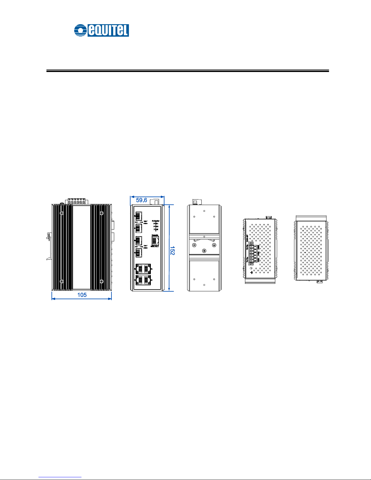
The figure below illustrates the dimensions 59.6mm x 152mm x 105mm (W x H x D) for
the Managed Industrial Switch.
Mechanical Dimensions
Page 16
September 2011 Ed.2.0
EQUITEL – Technical Manual N968
9
LED Indicators
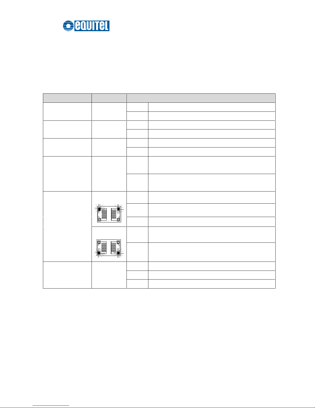
LED indicators located on the front panel display the power status and network status
of the Managed Industrial Switch. Please refer to the following table for further details.
LED
Color
Description
R-Master
Green
On
The switch is the master device of the X-ring group
Off
Non-master device
PWR1
Green
On
Power input 1 is active
Off
Power input 1 is inactive
PWR2
Green
On
Power input 2 is active
Off
Power input 2 is inactive
P-Fail
(depends on the
Fault Relay Alarm
configuration)
Red
On
Power or Ethernet port linking failure occurs
Off
No failure occurs
P1 ~ P4
(10/100/1000T)
Green
On
Connected to network
Blinks
Data is transmitting or receiving
Off
Not connected to network
Green
On
1000M
Off
Disconnected or 10/100M
P5 ~ P8
(100/1000 SFP)
Green
On
Connected to network
Blinks
Data is transmitting or receiving
Off
Not connected to network
Definition of LED indicators
Page 17
September 2011 Ed.2.0
EQUITEL – Technical Manual N968
10
Installation
RJ-45 Cabling
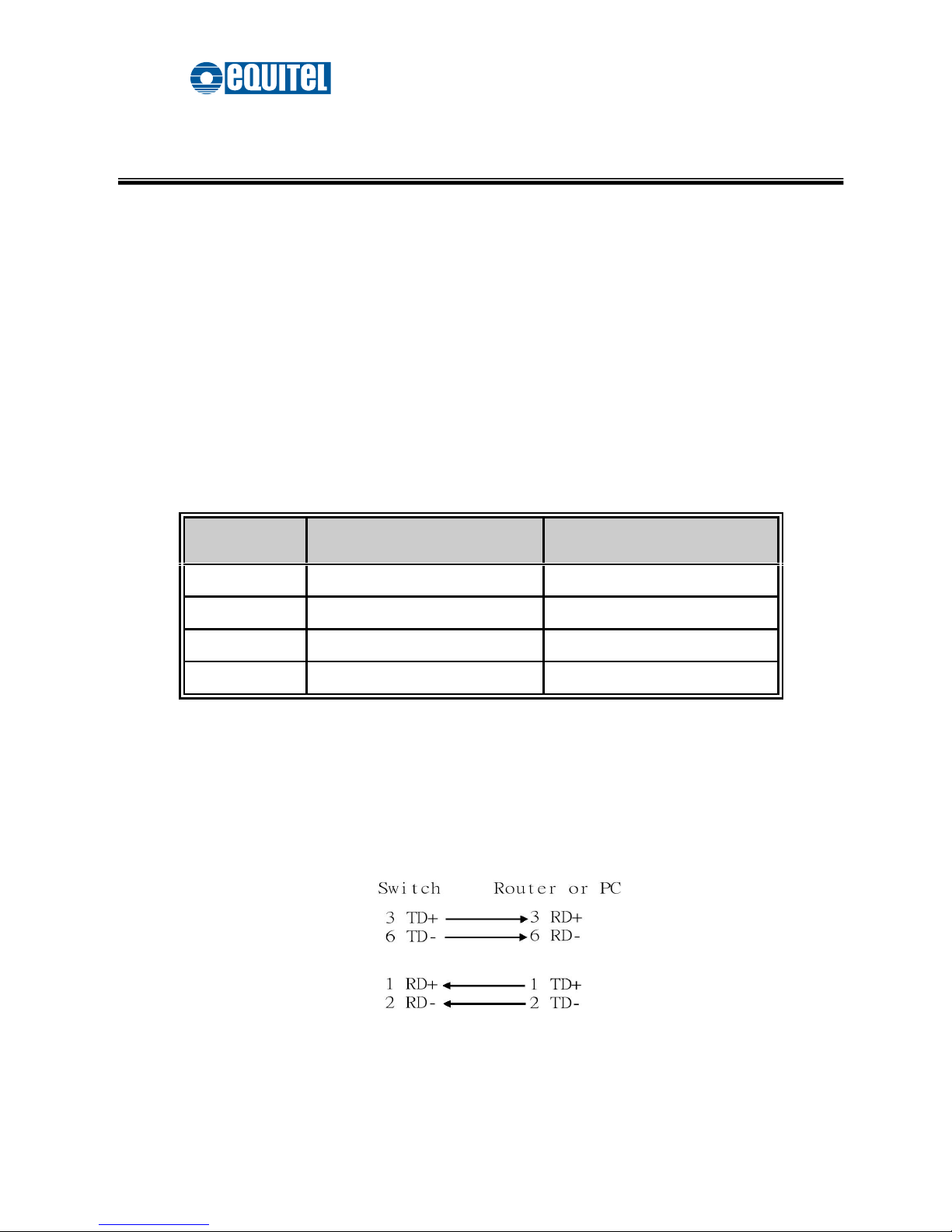
Use four twisted-pair, Category 5e or above cabling for RJ-45 port connection. The cable
between the switch and the link partner (switch, hub, workstation, etc.) must be less than
100 meters (328 ft.) long. The RJ-45 copper ports will auto-sense for 10Base-T,
100Base-TX, or 1000Base-T connections. Auto MDI/MDIX means that the switch can
connect to another switch or workstation without changing straight through or crossover
cabling.
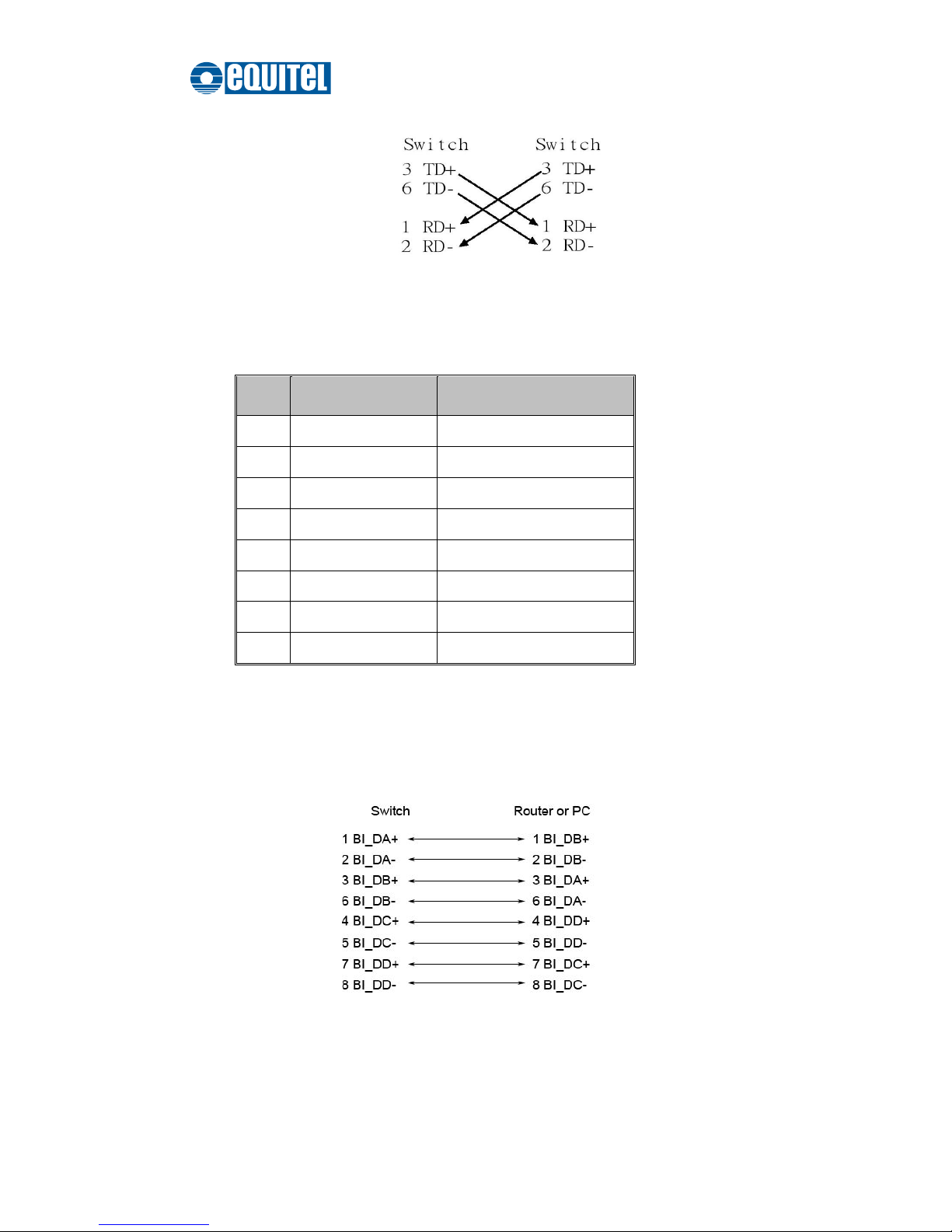
10/100Base-TX Pinouts
Pin Number
MDI-X Signal Name
MDI Signal Name
1
Receive Data plus (RD+)
Transmit Data plus (TD+)
2
Receive Data minus (RD-)
Transmit Data minus (TD-)
3
Transmit Data plus (TD+)
Receive Data plus (RD+)
6
Transmit Data minus (TD-)
Receive Data minus (RD-)
[Note]
“+” and “-” signs represent the polarity of the wires that make up each wire pair.
10/100Base-TX Cable Schema
Straight Through Cable Schematic
Page 18
September 2011 Ed.2.0
EQUITEL – Technical Manual N968
11
Cross Over Cable Schematic
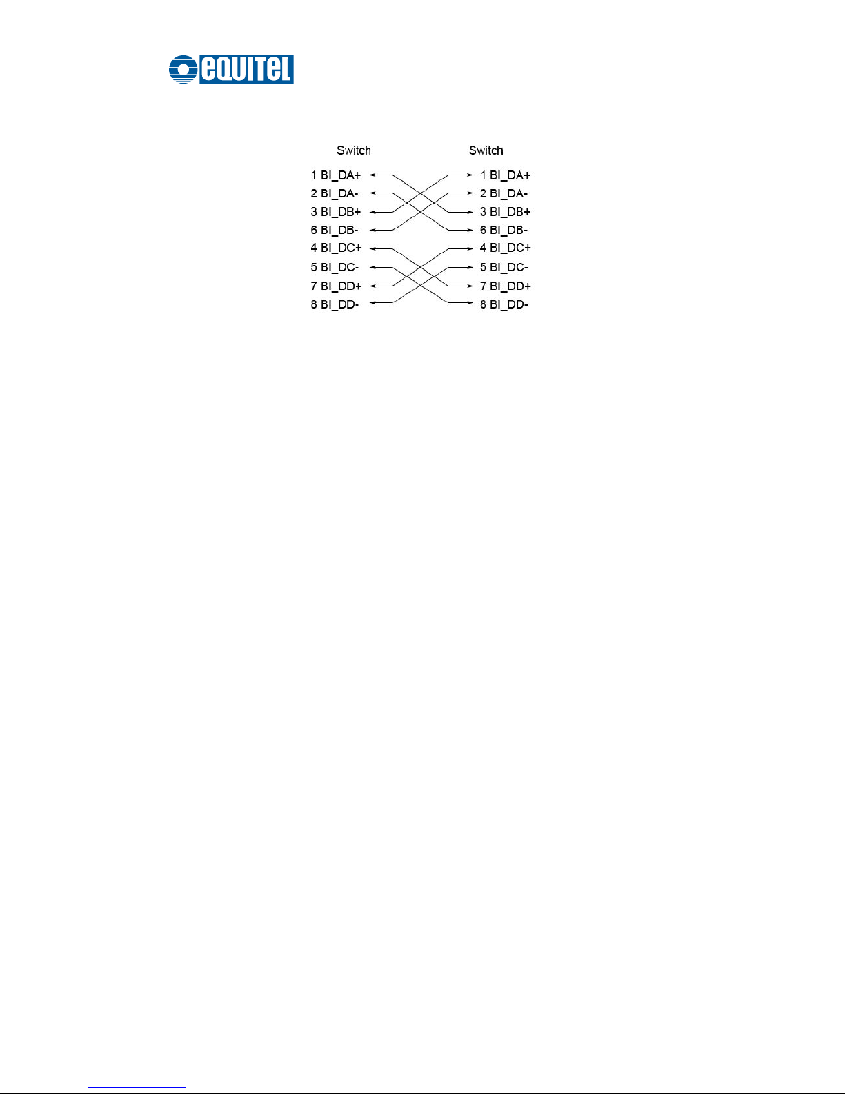
10/100/1000Base-T Pinouts
The table below describes the gigabit Ethernet RJ-45 pinouts.
Pin
Signal name
Description
1
BI_DA+
Bi-directional pair A+
2
BI_DA-
Bi-directional pair A-
3
BI_DB+
Bi-directional pair B+
4
BI_DC+
Bi-directional pair C+
5
BI_DC-
Bi-directional pair C-
6
BI_DB-
Bi-directional pair B-
7
BI_DD+
Bi-directional pair D+
8
BI_DD-
Bi-directional pair D-
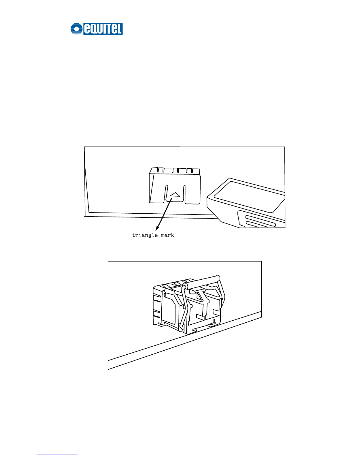
10/100/1000Base-T Cable Schema
The following two figures illustrate the 10/100/1000Base-T cable schema.
Straight Through Cable Schema
Page 19
September 2011 Ed.2.0
EQUITEL – Technical Manual N968
12
Crossover Cable Schema
Page 20
September 2011 Ed.2.0
EQUITEL – Technical Manual N968
13
SFP Cabling
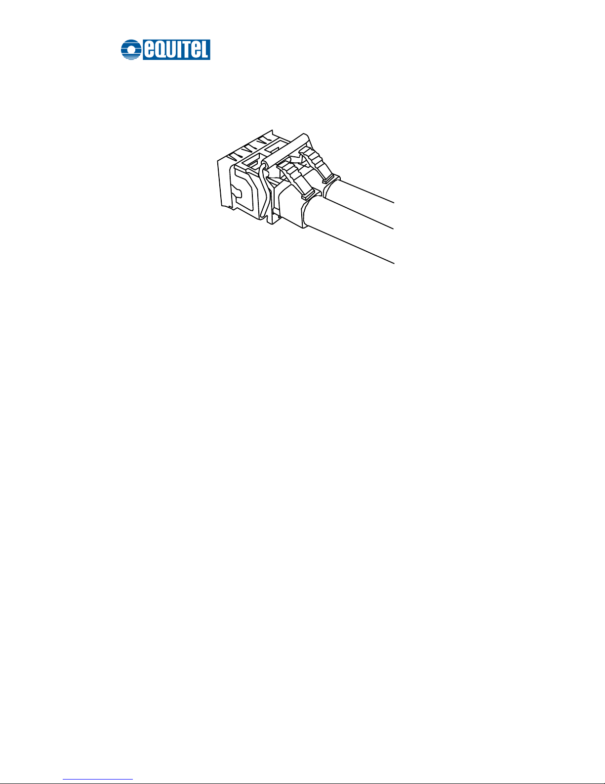
SFP Connection
To connect the transceiver and the LC cable, please follow the steps shown below:
First, insert the transceiver into the SFP slot. Notice that the triangle mark indicates the
bottom of the slot.
Insert transceiver into the SFP slot
Transceiver Inserted
Page 21
September 2011 Ed.2.0
EQUITEL – Technical Manual N968
14
Second, insert LC connector of the fiber cable into the transceiver.
LC connector to the transceiver
Page 22
September 2011 Ed.2.0
EQUITEL – Technical Manual N968
15
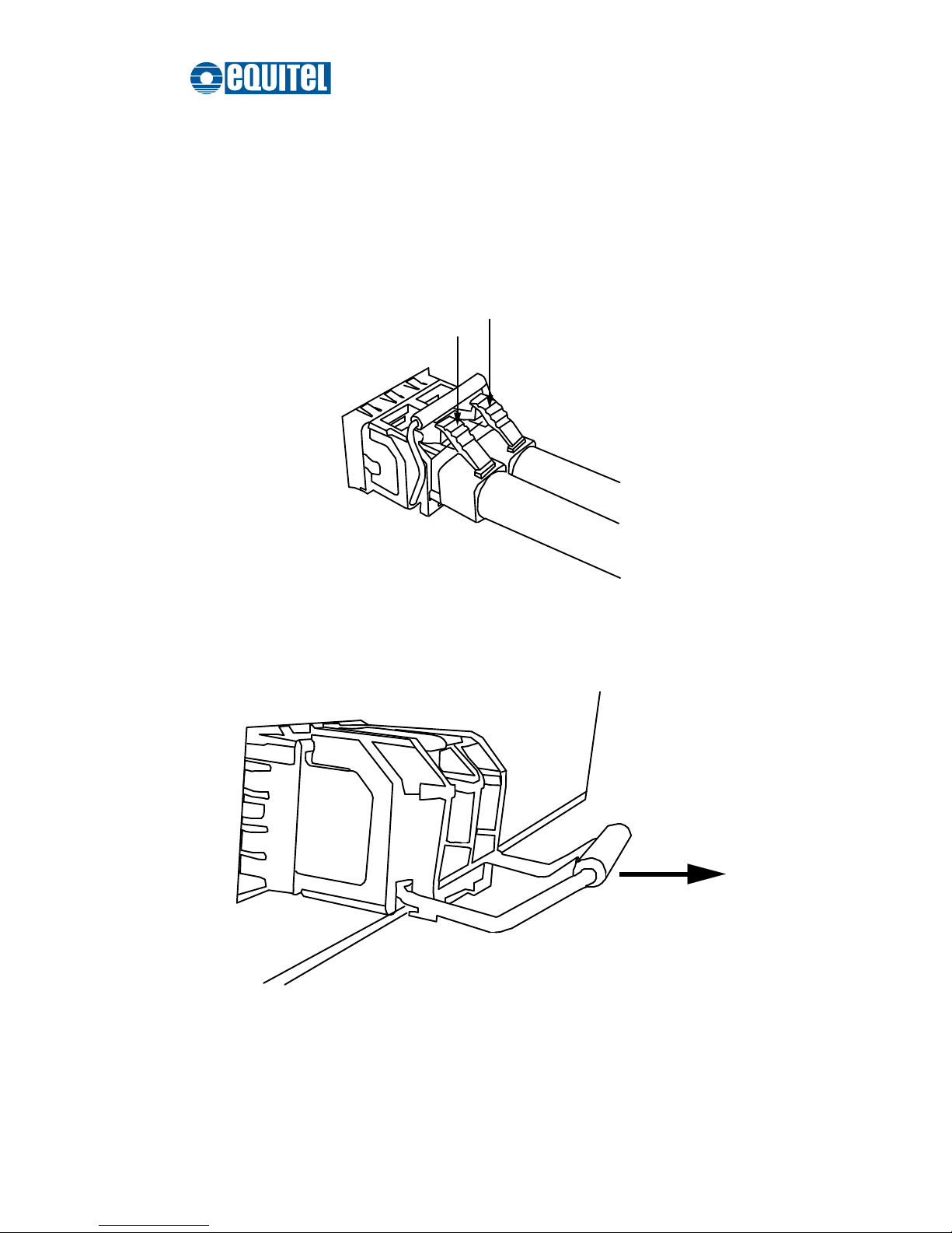
SFP Disconnection
To remove the LC connector from the transceiver, please follow the steps below:
First, press down the latches and pull the LC connector out of the transceiver.
Press down the latches to remove the LC connector
Second, push down the metal loop and pull out the transceiver by the handle.
Pull the transceiver out of the slot
Page 23
September 2011 Ed.2.0
EQUITEL – Technical Manual N968
16
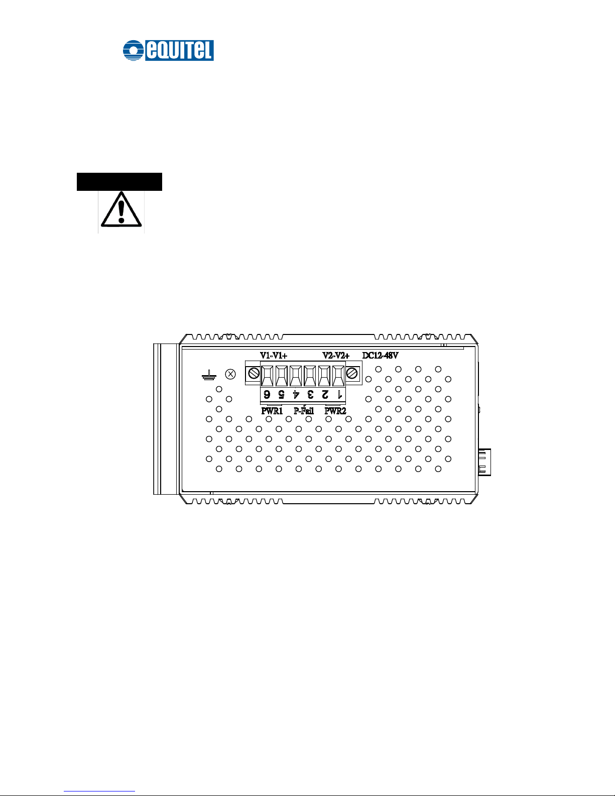
Grounding the Industrial Switch
Follow the instructions below to attach the industrial switch to ground.
When installing the industrial switch, the ground connection must
always be made first and disconnected last.
1. On the top of the industrial switch, locate and remove the dome screw which has a
ground symbol beside it.
2. Attach the ground wire to the screw hole with the dome screw.
ATTENTION
Page 24
September 2011 Ed.2.0
EQUITEL – Technical Manual N968
17
Wiring the Power Inputs
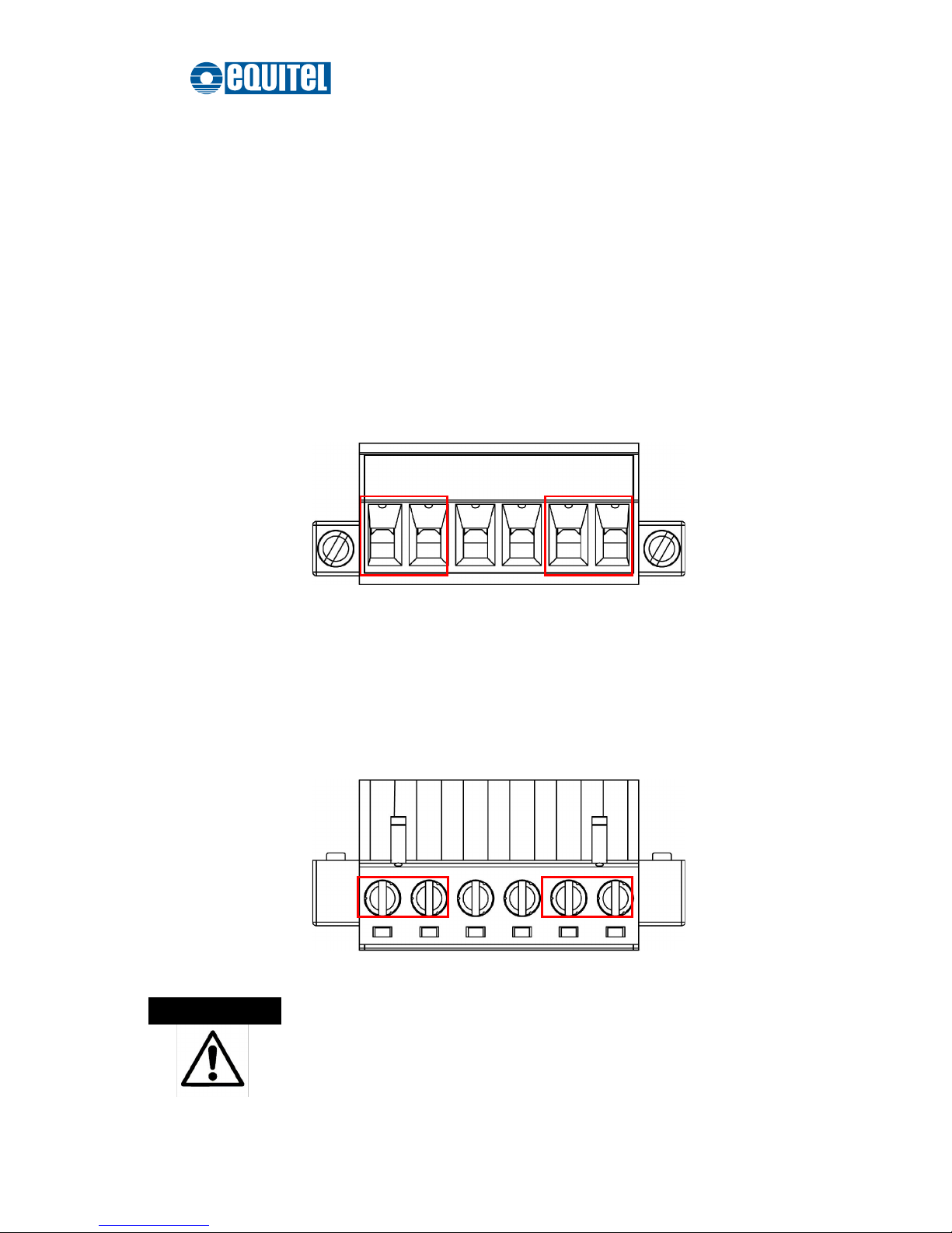
Please follow the steps below to wire power lines from the terminal block to the compliant
external DC power source.
1. Before wiring, make sure the power source is disconnected.
2. Using the wire-stripping tool, strip a short piece of insulation from the output wires of
the DC power source.
3. Identify the positive and negative feed positions for the terminal block connection.
See the symbols printed on the panel indicating the polarities and DC input power
range in voltage.
Plugs for Power 1 & Power 2
4. Insert the exposed wires into the terminal block plugs. Only wires with insulation
should extend from the terminal block plugs. Note that the polarities between the
wires and the terminal block plugs must be positive to positive and negative to
negative.
5. Use a slotted screwdriver to tighten the captive screws.
Captive Screws for Fixing Wires
Use Copper Conductors Only, 60/75C, tightening to 5 lb-in
The wire gauge for the terminal block should be in the range
between 12~ 24 AWG.
ATTENTION
Page 25

September 2011 Ed.2.0
EQUITEL – Technical Manual N968
18
Page 26
September 2011 Ed.2.0
EQUITEL – Technical Manual N968
19
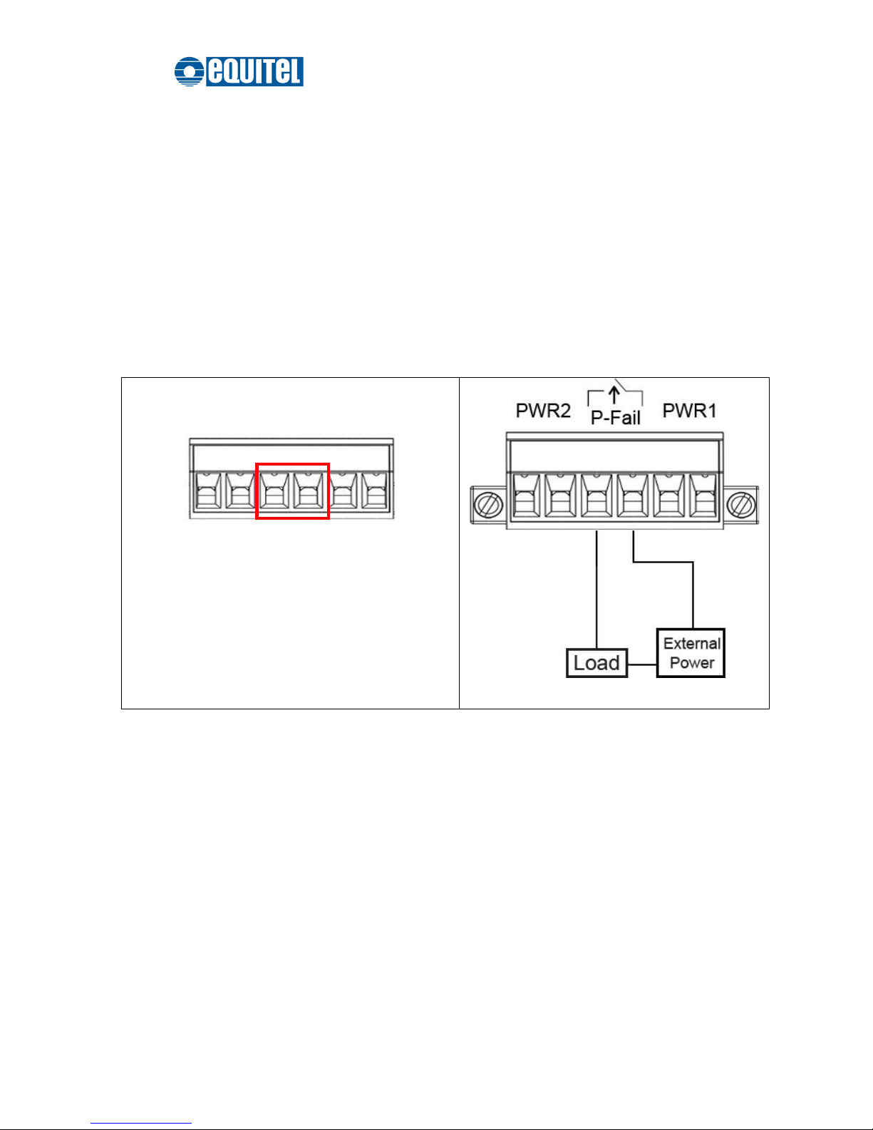
Wiring the P-Fail Alarm Contacts
The “P-Fail” alarm relay is provided to signal critical error conditions that may occur on
the switch. The contacts are energized upon powering up of the switch and remain
energized until a critical error occurs including power failure and Ethernet port
disconnection. Take the wiring illustration below as an example that illustrates the proper
relay connection forming a normally closed circuit, and the connection is to be broken
when an error occurs.
Terminal Block Plugs for Fault Alarm Contacts
Fault Alarm Wiring Example
24Vdc, 1A
Resistance
Page 27
September 2011 Ed.2.0
EQUITEL – Technical Manual N968
20
DIN-Rail Mounting
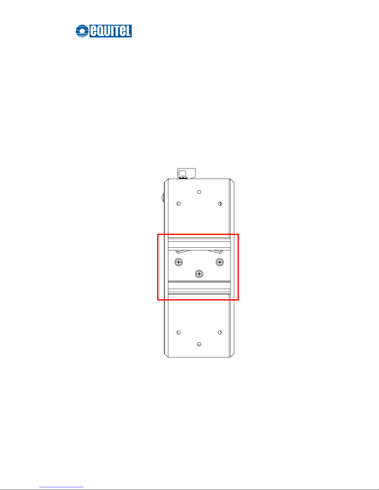
Assembling the DIN-Rail Clip
The DIN-rail clip is screwed on the industrial switch when out of factory. If not, please
refer to the following steps to secure the DIN-rail clip on the switch.
1. Use the included screws to secure the DIN-rail clip on the industrial switch.
2. To remove the DIN-rail clip, reverse step 1.
Rear Side of the Switch
DIN-Rail Clip
Page 28

September 2011 Ed.2.0
EQUITEL – Technical Manual N968
21
Hanging the Industrial Switch
Follow the steps below to hang the industrial switch on the DIN rail.
1. First, position the rear side of the switch directly in front of the DIN rail. Make sure
the top of the clip hooks over the top of the DIN rail.
2. Push the unit downward.
3. Check the DIN-Rail clip is tightly fixed on the DIN rail.
4. To remove the industrial switch from the track, reverse the steps above.
Page 29

September 2011 Ed.2.0
EQUITEL – Technical Manual N968
22
Wall Mounting
To hang the Ethernet switch on the wall, please follow the steps below.
1. Remove the DIN-rail clip.
2. Prepare the two wall-mount plates and six screws included.
3. Align the screw holes bewteen the wall-mount plates and the unit as the figure illustrated.
4. Secure the plates to the unit with the accompanying screws.
Page 30

September 2011 Ed.2.0
EQUITEL – Technical Manual N968
23
Installation Steps
1. Unpack the Industrial switch.
2. To hang the Industrial switch on the wall, please refer to the Wall Mounting section.
3. Ground the industrial switch.
4. To power on the Industrial switch, please refer to the Wiring the Power Inputs
section for further information on how to wire the power. And then the power LED on
the Industrial switch will light up. Please refer to the LED Indicators section for
indication of LED lights.
5. Prepare the appropriate cables for Ethernet connection.
6. The Ethernet port LED on the Industrial switch will light up when the cable is
connected with the network device. Please refer to the LED Indicators section for
LED light indication.
7. When all connections are set and LED lights all show in normal, the installation is
complete.
Note
This equipment is intended for use in a Pollution Degree 2
industrial environment.
Page 31
September 2011 Ed.2.0
EQUITEL – Technical Manual N968
24
Configuration
The industrial switch can be configured via RS-232 Console, SSH (Secure Shell) or a
web browser.
RS-232 Console
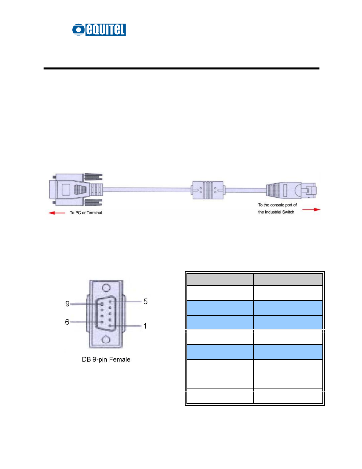
Attach the supplied cable, which one end is D-sub 9 and the other end is RJ-45, to
connect the the industrial switch and your host PC or terminal. The connected PC or
terminal must support the terminal emulation program.
Pin Assignments
D-sub 9 Connector
RJ-45 Connector
NC
1 Orange/White
2
2 Orange
3
3 Green/White
NC
4 Blue
5
5 Blue/White
NC
6 Green
NC
7 Brown/White
NC
8 Brown
Page 32
September 2011 Ed.2.0
EQUITEL – Technical Manual N968
25
Login in the Console Interface
After the connection between Switch and PC is ready, turn on the PC and run a terminal
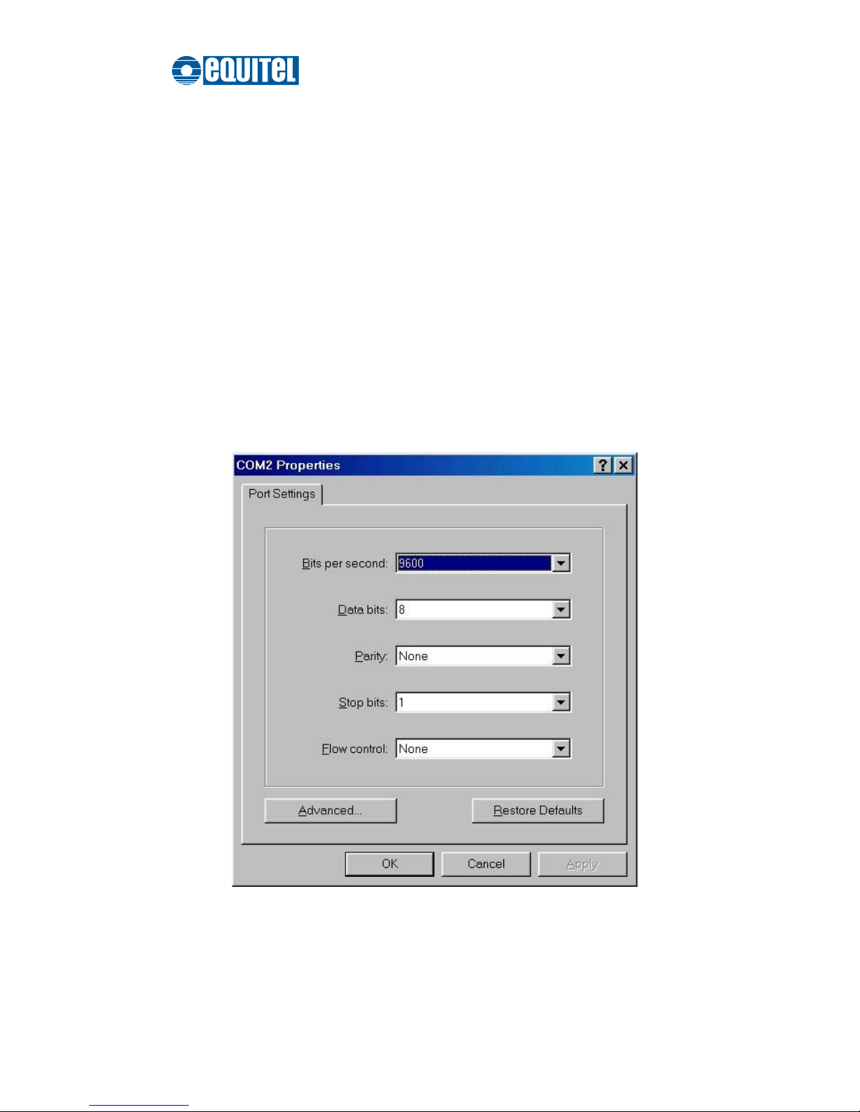
emulation program like Hyper Terminal and configure its communication parameters
to match the following default characteristics of the console port:
Baud Rate: 9600 bps
Data Bits: 8
Parity: none
Stop Bit: 1
Flow control: None
The settings of communication parameters
Page 33
September 2011 Ed.2.0
EQUITEL – Technical Manual N968
26
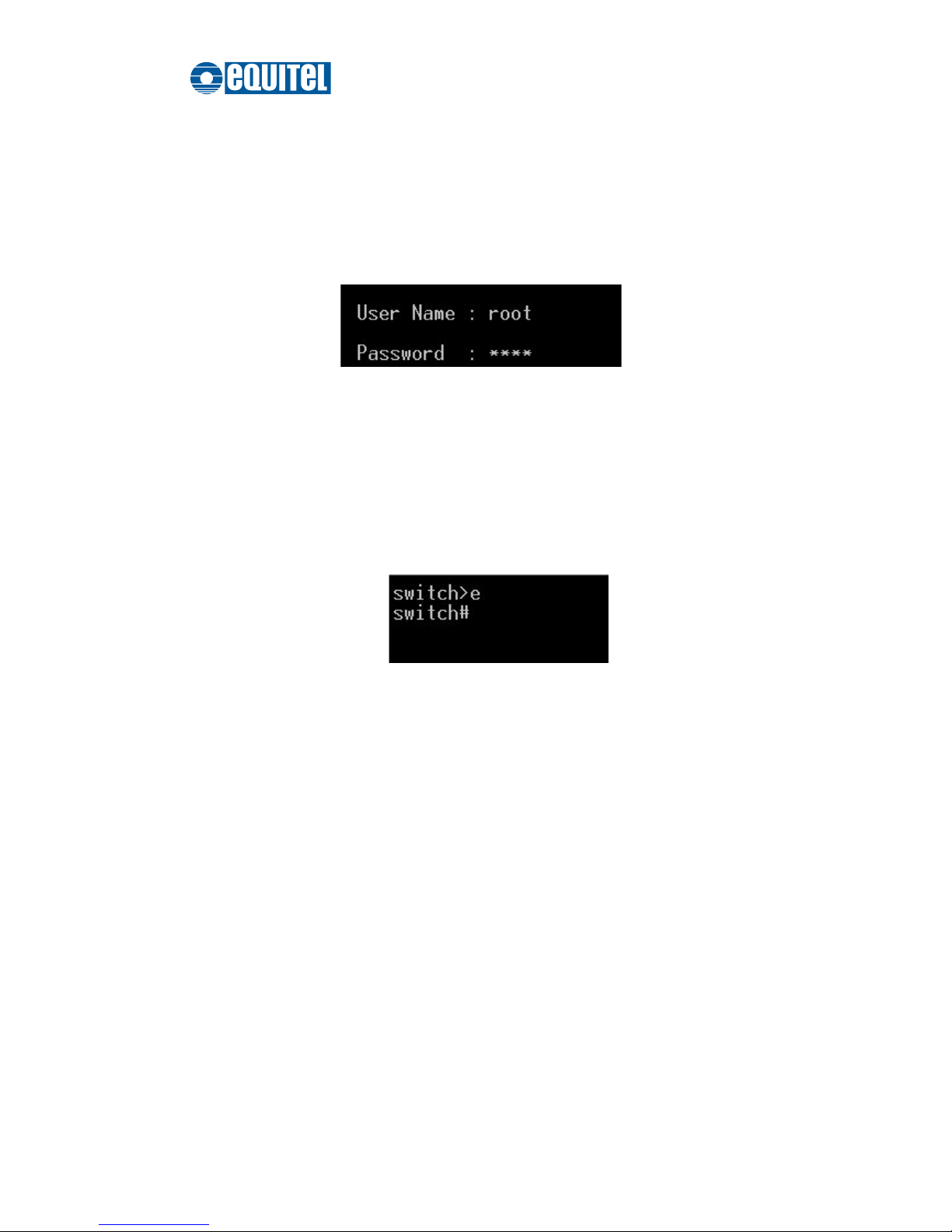
Having finished the parameter settings, click ‘OK’. When the blank screen shows up,
press Enter to have the login prompt appear. Key in ‘root’ (default value) for both User
Name and Password (press Enter to switch between); and then press Enter to have the
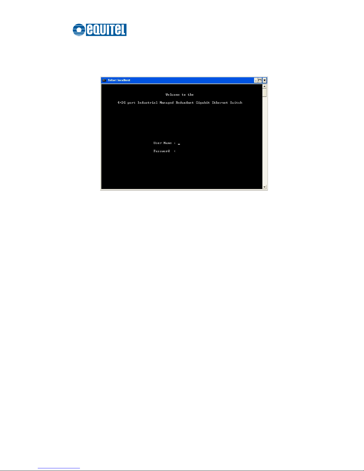
Main Menu of console management show up. Please see the figure below.
Console login interface
The system supports the console management—CLI command. After you log in on to the
system, you will see a command prompt. To enter CLI management interface, type in
“enable” command.
CLI command interface
For further details about the CLI commands, please refer to Appendix A Command
Sets.
Page 34
September 2011 Ed.2.0
EQUITEL – Technical Manual N968
27
SSH
The Ethernet switch also supports SSH (Secure SHell) which allows the user to log in
from a remote computer over the network.
The next section is intended to guide users on how to use an SSH client—PuTTY to
make a connection to the Ethernet switch.
Configuring PuTTY
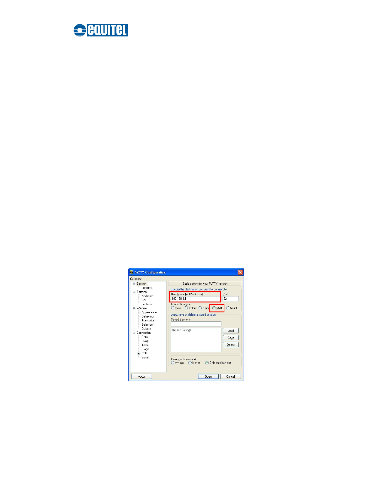
Launch PuTTy, and you will see a dialog box which allows you to control everything
PuTTY can do. You don’t usually need to change most of the configuration options. To
start the simplest kind of session, please follow the steps below.
1. In the ‘Host Name (or IP address)’ field, enter the Internet host name or IP address of
the server you want to connect to.
2. Now select a login session protocol to use, from the ‘Connection type’ radio buttons.
For a login session, you should always select SSH.
Basic Options for PuTTY
Page 35
September 2011 Ed.2.0
EQUITEL – Technical Manual N968
28
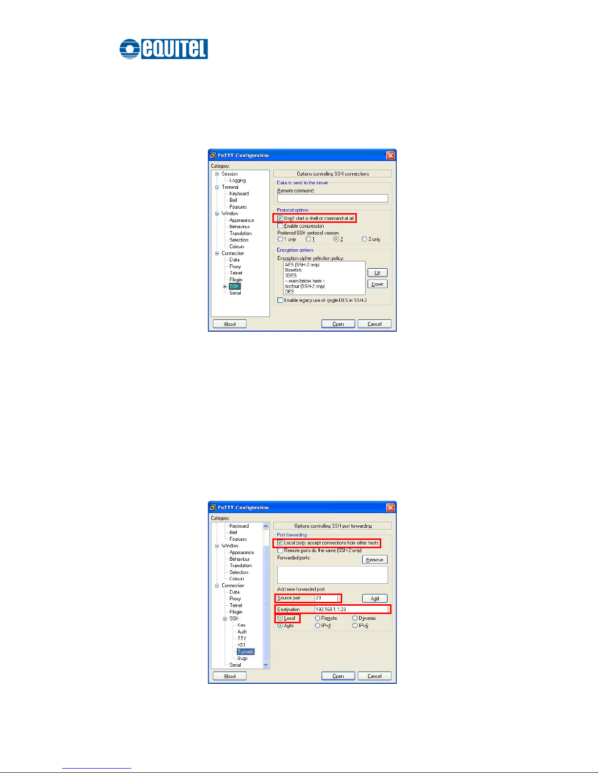
3. Click the Connection SSH node of the tree-menu to configure options for
controlling SSH connections.
4. Tick the check box labeled ‘Don’t start a shell or command at all’.
Options Controlling SSH Connections
5. Click the Connection SSHTunnel node of the tree-menu to configure options for
controlling SSH port forwarding.
6. Tick the check box labeled ‘Local ports accept connection from other hosts’ that
allows you to set up local-to-remote port forwardings (including dynamic port
forwardings) in such a way that machines other than your client PC can connect to the
forwarded port.
7. Add a new forwarded port to connect to the SSH server and set the type to ‘’Local.
Page 36
September 2011 Ed.2.0
EQUITEL – Technical Manual N968
29
Options Controlling SSH Port Forwarding
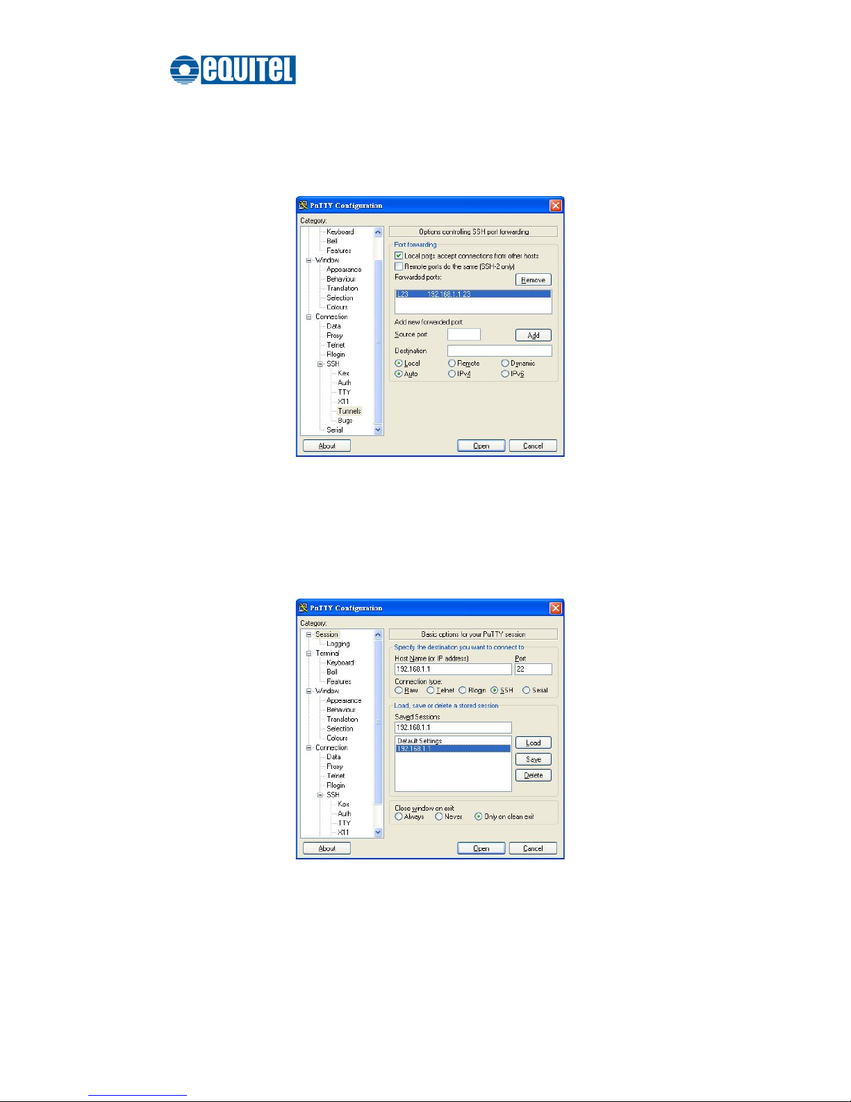
8. After filling in, click the Add button. And you will see an entry added to the list box.
Entry of Port Forwarding Added
9. You can also save your preferred PuTTY options for quick connection the next time.
Just go back to the Session node, and click the Save button with a session name filled.
When you see the saved session in the list box, the session is saved.
Saving Sessions
Page 37
September 2011 Ed.2.0
EQUITEL – Technical Manual N968
30
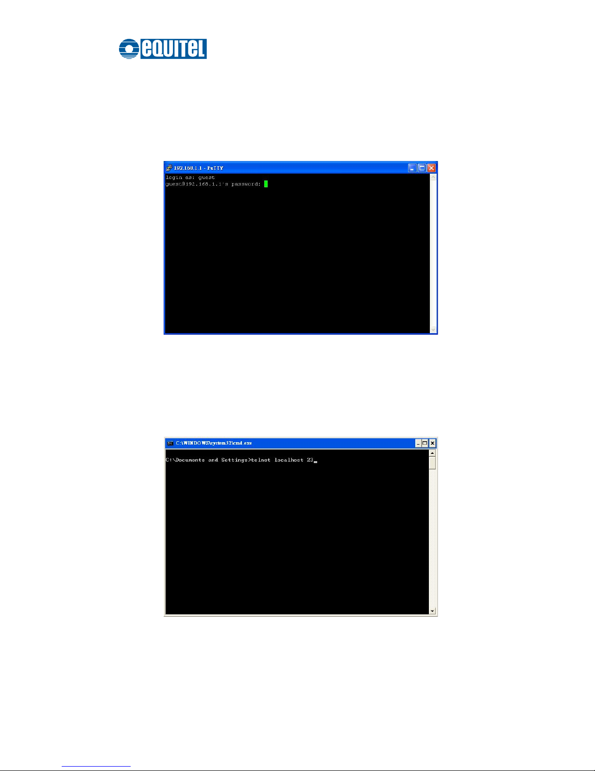
10. To connect to the SSH server, select the session name and click the Open button.
And then you will see a window shows up with prompt message ‘login as:’. Type
‘guest’ for both user name and password.
Logging-in interface
11. Run the ‘cmd’ command to start the command prompt interface. Type ‘telnet
localhost 23’ and press Enter.
Command Prompt interface
Page 38
September 2011 Ed.2.0
EQUITEL – Technical Manual N968
31
12. When finished, a telnet session is successfully made using the SSH protocol.
Console via SSH
Page 39

September 2011 Ed.2.0
EQUITEL – Technical Manual N968
32
Web-Based Management
This industrial switch provides a convenient configuring way via web browser. You can
follow the steps below to access the equipment.
Your host PC should be in the same VLAN setting with the industrial
switch, or the management will not be configured.
Connect the industrial switch to the Ethernet then your host PC could be configured via
Ethernet. Or you can directly connect it to your host PC with a straight-through or cross
over Ethernet cable.
Before to use web management, install the industrial switch on the network and make
sure that any one of the PCs on the network can connect with the industrial switch
through the web browser. The industrial switch default value of IP, subnet mask,
username and password are as below.
IP Address: 192.168.16.1
Subnet Mask: 255.255.255.0
Default Gateway: 192.168.16.254
User Name: root
Password: root
[NOTE]
Don’t set “0” for the first segment of the subnet mask and default gateway
(000.xxx.xxx.xxx).
Refresh the web screen if the web could not be displayed while you change
the setting.
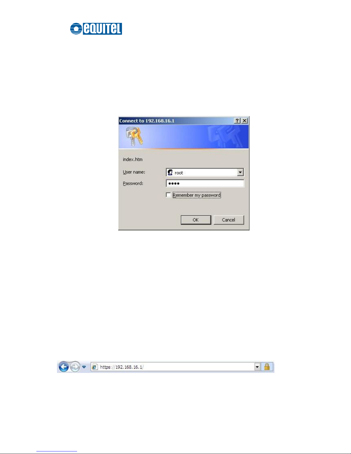
1. Launch the Internet Explorer on the PC.
2. Type the IP address of the switch in the URL field, and then Press “Enter”.
Note
Page 40
September 2011 Ed.2.0
EQUITEL – Technical Manual N968
33
3. With the login dialog box showing up, type the user name and password in the
respective fields. The default user name and password are the same as ‘root’.
4. Press Enter or click the OK button, and then the home screen of the Web-based
management appears. You can change user name/password in the User
Authentication section.
Login dialog box
SSL
The Ethernet switch also provides an option for you to connect with your browser via
HTTP over SSL, called HTTPS. The SSL (Secure Socket Layer) protocol allows users to
make a secured session between the browser (client) and the Ethernet switch (server).
You can then type the prefix “https://“ followed by the IP address of the Ethernet switch in
the URL of the browser. Beside the URL a padlock icon shows up indicating that client is
successfully connecting to server via HTTPS.
Page 41

September 2011 Ed.2.0
EQUITEL – Technical Manual N968
34
In the main page, you can find the tree menu structure of the Ethernet switch in the left
side. Click the “+” symbol to unroll the hiding hyperlink, and click any one of the
hyperlinks to open its function page.
Page 42
September 2011 Ed.2.0
EQUITEL – Technical Manual N968
35
System Information
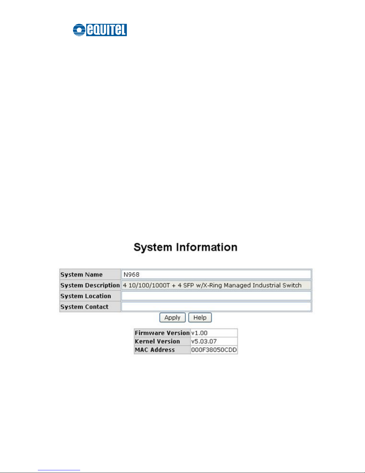
Here you can view the system information and assign the system name and location to
make this switch more easily identified on your network.
System Name: Assign the name of the switch. The maximum length is 64 bytes.
System Description: A read-only field displaying the description of the switch.
System Location: Assign the switch physical location. The maximum length is 64
bytes.
System Contact: Enter the name of contact person or department.
Firmware Version: Displays the switch’s firmware version.
Kernel Version: Displays the kernel software version.
MAC Address: Displays the unique hardware address assigned by manufacturer
(default).
Click Apply to have the configuration take effect.
System Information interface
Page 43

September 2011 Ed.2.0
EQUITEL – Technical Manual N968
36
IP Configuration
Due to the foreseeable address exhaustion of IPv4, the IP configuration of the Ethernet
switch is designed to provide an interface for users to configure the switch running both
IPv4 and IPv6 architecture.
IPv4
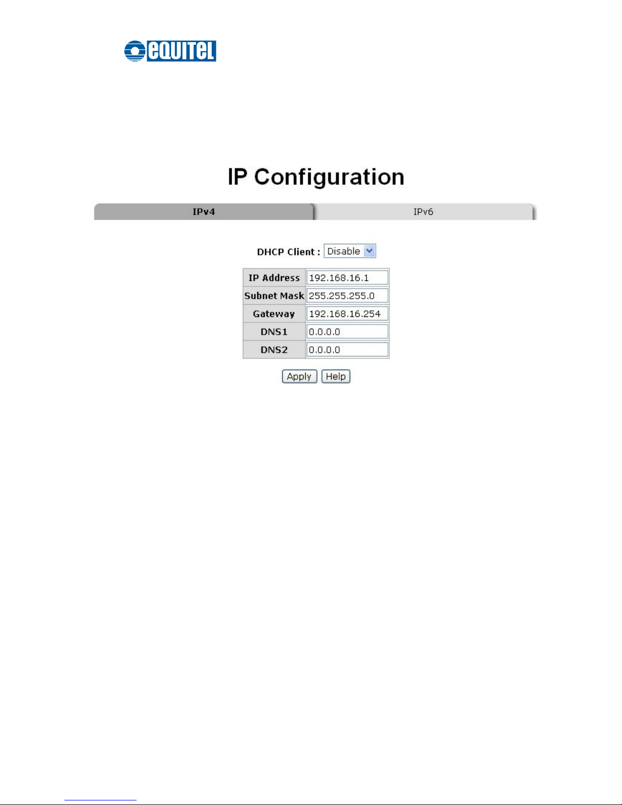
The IPv4 tab allows users to configure the switch to receive an IP address from DHCP
server or manually fill in
IP Address,Subnet Mask,Gateway
, IP addresses of the
primary and the secondary DNS servers.
DHCP Client: Enable or disable the DHCP client function. When the DHCP Client
function is enabled, the industrial switch will be assigned an IP address from the
network DHCP server. The default IP address will be replaced by the assigned IP
address on DHCP server. After users click Apply, a popup dialog shows up. It is to
inform the user that when the DHCP client is enabled, the current IP will lose and the
user should find the new IP on the DHCP server
IP Address: Assign the IP address for the industrial switch. With the DHCP
Client function enabled, the switch is configured as a DHCP client and users doesn’t
need to assign the IP address that is assigned by the DHCP server. The default IP is
192.168.16.1 or the user has to assign an IP address manually when DHCP Client is
disabled.
Subnet Mask: Assign the subnet mask to the IP address. If the DHCP Client
function is disabled, the user has to assign the subnet mask manually.
Gateway: Assign the network gateway for the switch. If the DHCP Client function is
disabled, the user has to assign the gateway manually. The default gateway is
192.168.16.254.
DNS1: The abbreviation of Domain Name Server—an Internet service that translates
domain names into IP addresses. The domain name is in alphabetic order, which is
easy to be remembered. The Internet is based on IP address. Therefore, every time
you use a domain name, a DNS service must translate the name into the
corresponding IP address. For example, the domain name www.net.com might
Page 44
September 2011 Ed.2.0
EQUITEL – Technical Manual N968
37
translate to 192.168.16.1.
DNS2: The backup for DNS1. When DNS1 cannot function, DNS2 will then replace
DNS1.
When finished, click Apply to have the configuration take effect.
IP configuration—IPv4
Page 45
September 2011 Ed.2.0
EQUITEL – Technical Manual N968
38
IPv6
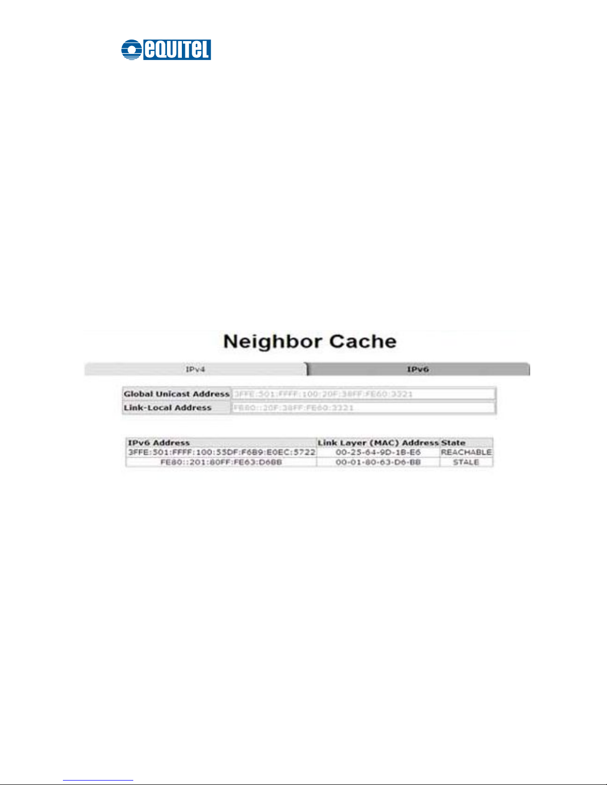
The IPv6 tab mainly features two fields displaying the Ethernet switch’s
Global Unicast
Address
and
Link-Local Address
.
Global Unicast Address
: A display-only field. When this Ethernet switch is connected to
a network segment where one or more routers connected, the Ethernet switch will be
assigned an address known as Global Unicast Address by the router(s). Being assigned
the Global Unicast Address, the Ethernet switch can then have access to different
network segments.
Link-Local Address
: A display-only field. Link-Local Address is for use during
auto-configuration and when no any router presents. Being assigned the Link-Local
Address, the Ethernet switch can have access to all hosts on the same local segment to
where it belongs.
IP configuration—IPv6
Page 46

September 2011 Ed.2.0
EQUITEL – Technical Manual N968
39
DHCP Server
DHCP is the abbreviation of Dynamic Host Configuration Protocol that is a protocol for
assigning dynamic IP addresses to devices on a network. With dynamic addressing, a
device can have a different IP address every time it connects to the network. In some
systems, the device's IP address can even change while it is still connected. DHCP
also supports a mix of static and dynamic IP addresses. Dynamic addressing simplifies
network administration because the software keeps track of IP addresses rather than
requires an administrator to manage the task. This means that a new computer can be
easily added to a network without the hassle of manually assigning it a unique IP
address.
The system provides the DHCP server function. With the DHCP server function
enabled, the switch system is able to be configured as a DHCP server.
Page 47
September 2011 Ed.2.0
EQUITEL – Technical Manual N968
40
System Configuration
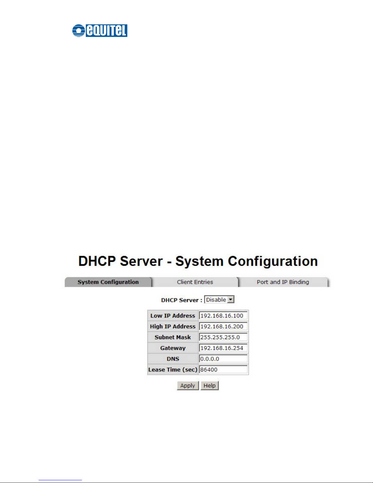
DHCP Server: This pull-down menu allows you to configure the switch to be the
DHCP server on your local network.
Low IP Address: Type in an IP address as the beginning of a range of the
dynamic IP address. As the figure shown below, for example, 192.168.16.100 is
the relatively low IP address of the range.
High IP Address: Type in an IP address as the beginning of a range of the
dynamic IP address. As the figure shown below, for example, 192.168.16.200 is
the relatively high IP address of the range.
Subnet Mask: Type in the subnet mask of the IP configuration.
Gateway: Type in the IP address of the gateway in your network.
DNS: Type in the IP address of Domain Name Server in your network.
Lease Time (sec): The length of time the dynamic IP addresses assigned to
clients.
Click Apply to have the configuration take effect.
DHCP Server—System Configuration interface
Page 48
September 2011 Ed.2.0
EQUITEL – Technical Manual N968
41
Client Entries
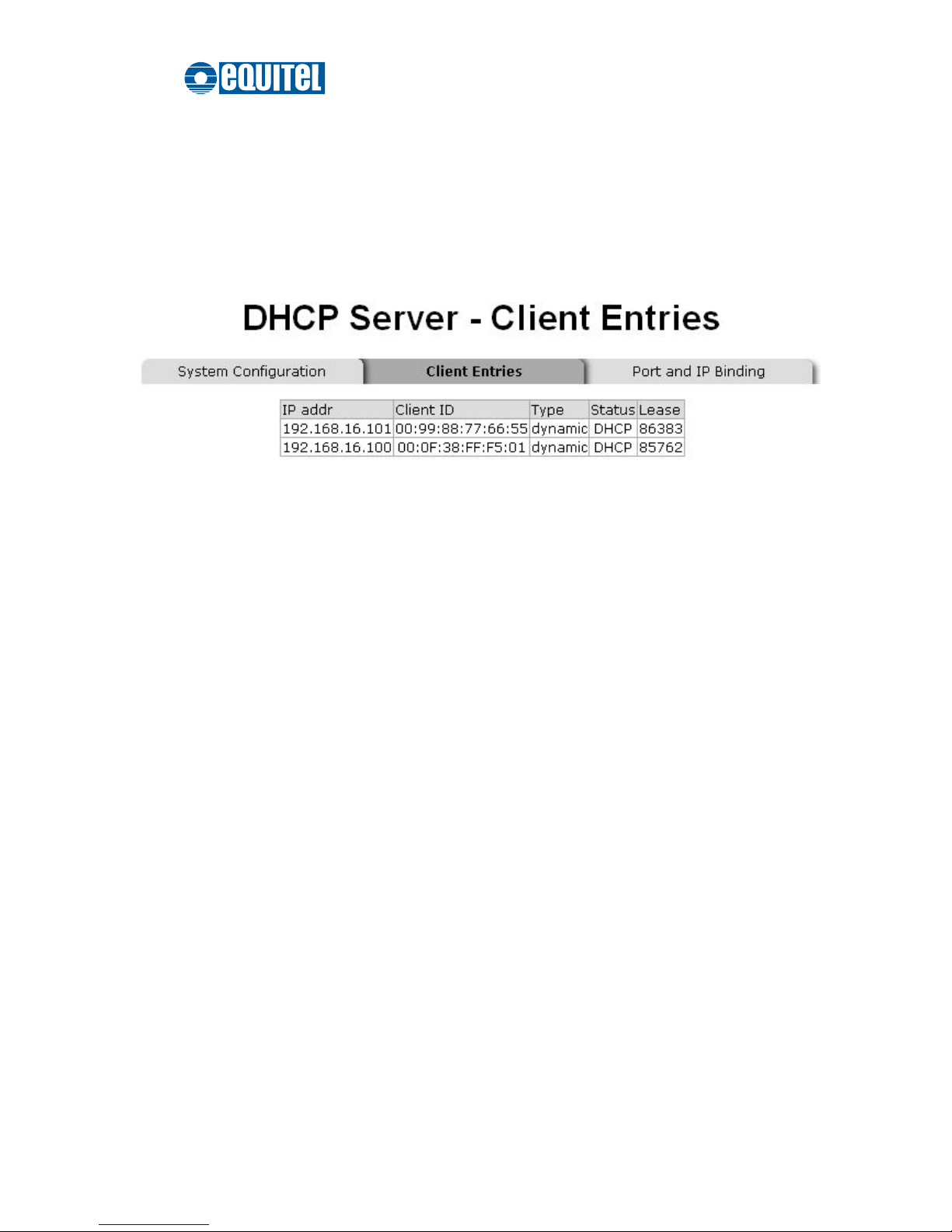
When the DHCP Server function is enabled, the system will collect the DHCP client
information including the assigned IP address, the MAC address of the client device,
the IP assigning type, states and lease time.
DHCP Client Entries interface
Page 49
September 2011 Ed.2.0
EQUITEL – Technical Manual N968
42
Port and IP Bindings
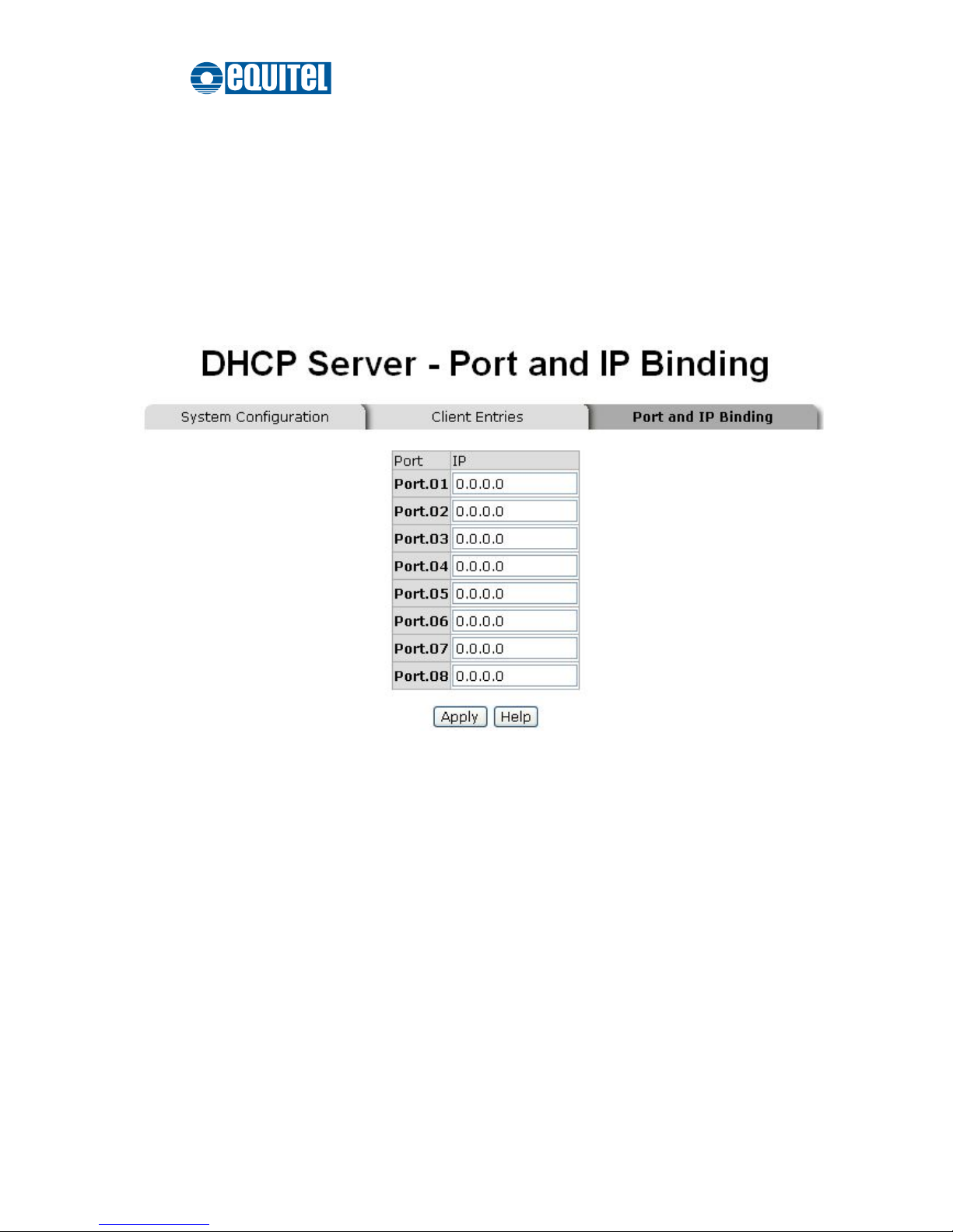
As the figure shown below, the switch will assign the IP address to the connected client
according to the Port-IP binding table. The user is allowed to fill each port with one
particular IP address. When the device is connecting to the port and asks for IP assigning,
the system will assign the IP address bound with the port to the device.
Port and IP Bindings interface
Page 50
September 2011 Ed.2.0
EQUITEL – Technical Manual N968
43
TFTP
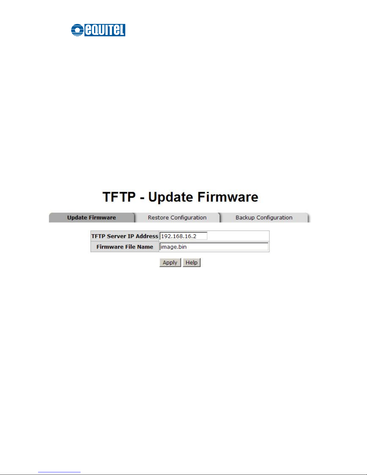
It provides the functions allowing the user to update the switch firmware via the Trivial
File Transfer Protocol (TFTP) server. Before updating, make sure the TFTP server is
ready and the firmware image is located on the TFTP server.
Update Firmware
TFTP Server IP Address: Type in the IP address of the TFTP server.
Firmware File Name: Type in the name of the firmware image file to be updated.
When finished, click Apply to start updating.
Update Firmware interface
Page 51
September 2011 Ed.2.0
EQUITEL – Technical Manual N968
44
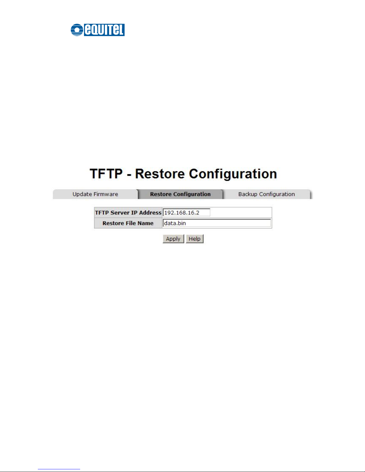
Restore Configuration
You can restore a previous backup configuration from the TFTP server to recover the
settings. Before doing that, you must locate the image file on the TFTP server first for
the switch to download back the flash image.
TFTP Server IP Address: Type in the IP address of the TFTP server.
Restore File Name: Type in the correct file name for restoring.
When finished, click Apply to start configuration restoration.
Restore Configuration interface
Page 52
September 2011 Ed.2.0
EQUITEL – Technical Manual N968
45
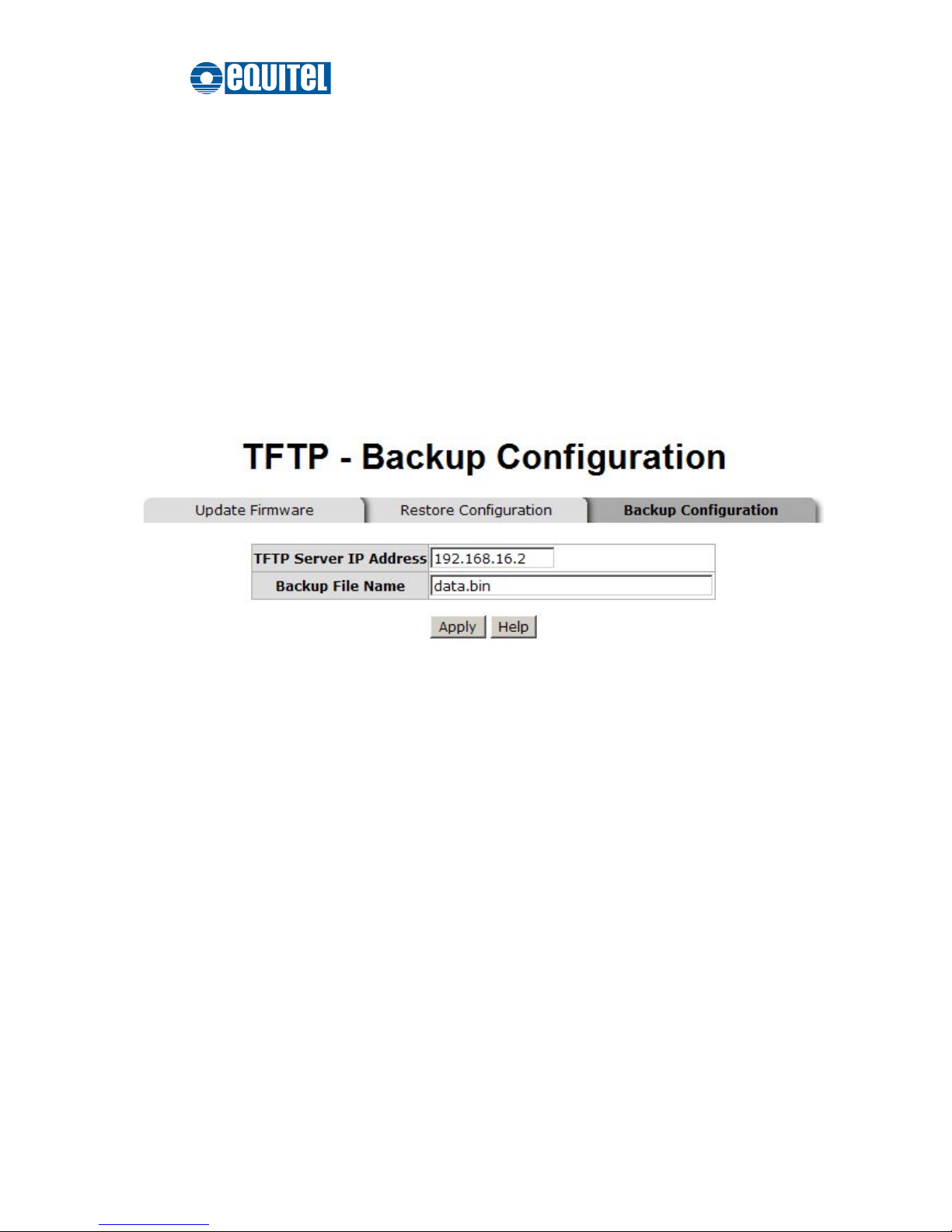
Backup Configuration
You can back up the current configuration from flash ROM to the TFTP server for the
purpose of recovering the configuration later. It helps you avoid wasting time on
configuring the settings by backing up the entire configuration.
TFTP Server IP Address: Type in the IP address of the TFTP server.
Backup File Name: Type in the file name.
When finished, click Apply to start backing up.
Backup Configuration interface
Page 53

September 2011 Ed.2.0
EQUITEL – Technical Manual N968
46
System Event Log
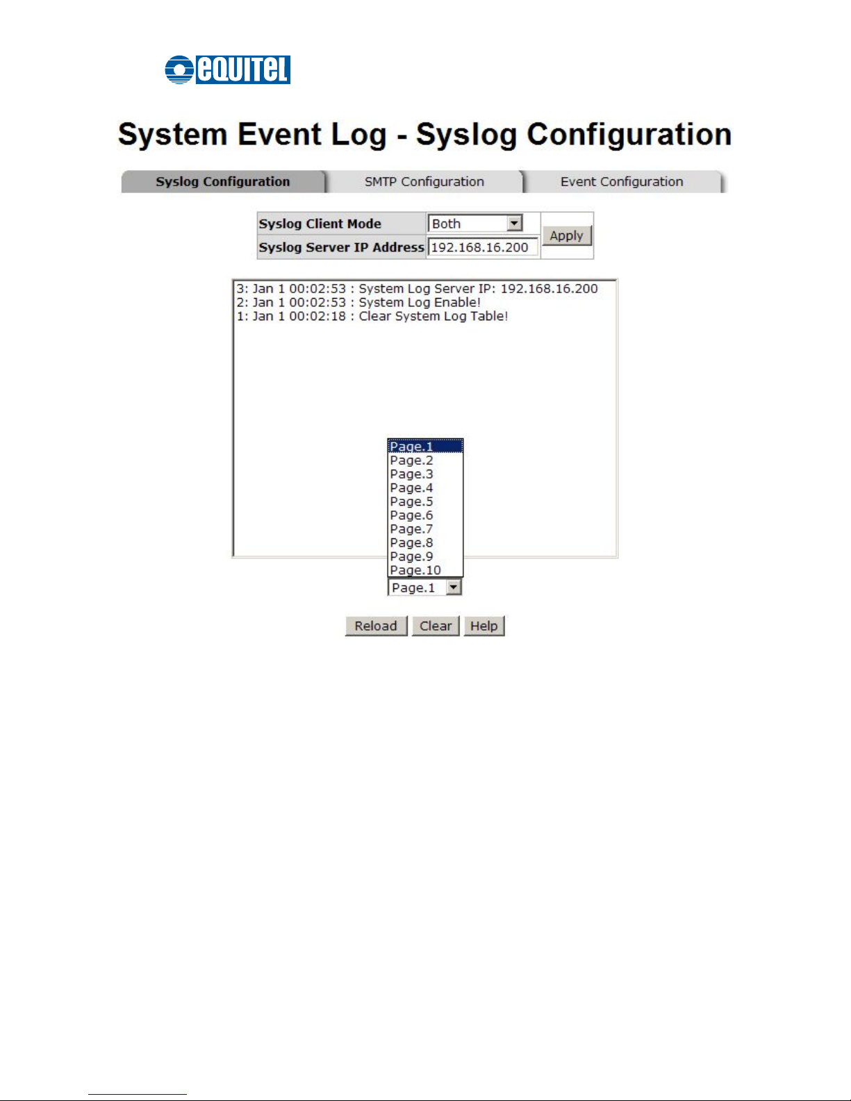
This page allows the user to decide whether to send the system event log, and select the
mode which the system event log will be sent to client only, server only, or both client and
server. What kind of event log will be issued to the client/server depends on the selection
on the Event Configuration tab.
System Event Log—Syslog Configuration
Syslog Client Mode: Select the system log mode—Client Only, Server Only, or
Both. ‘Client Only’ means the system event log will only be sent to this interface of the
switch, but on the other hand ‘Server Only’ means the system log will only be sent to
the remote system log server with its IP assigned. If the mode is set in ‘Both’, the
system event log will be sent to the remote server and this interface.
Syslog Server IP Address: When the ‘Syslog Mode’ item is set as Server Only/Both,
the user is required to assign the system log server IP address to which the log will be
sent.
Click Reload to refresh the event log displaying area.
Click Clear to clear the displaying area.
Make sure the selected mode and IP address, if needed, is correct and click Apply to
have the setting take effect.
Page 54
September 2011 Ed.2.0
EQUITEL – Technical Manual N968
47
Syslog Configuration interface
Page 55

September 2011 Ed.2.0
EQUITEL – Technical Manual N968
48
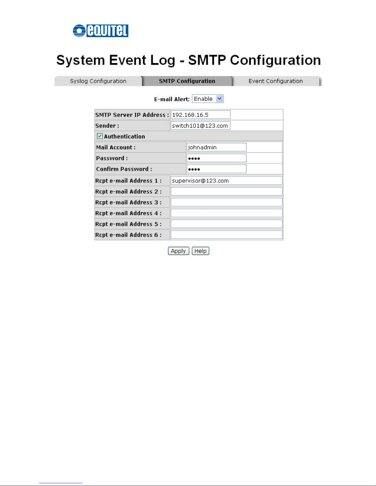
System Event Log—SMTP Configuration
Simple Mail Transfer Protocol (SMTP) is the standard for email transmissions across
the network. You can configure the SMTP server IP address, sender mail account,
password, and the recipient email account to which the e-mail alert will send. Besides,
this page provides the authentication mechanism including authentication steps
through which the client effectively logs in to the SMTP server during the process of
sending e-mail alert.
Email Alert: With this function enabled, the user is allowed to configure the detail
settings for sending the e-mail alert to the SMTP server when the events occur.
SMTP Server IP Address: Assign the mail server IP address (when Email Alert
is enabled, this field will then be available).
Sender: Type in an alias of the switch in complete email address format, e.g.
[email protected], to identify where the e-mail alert comes from.
Authentication: Tick the checkbox to have the mail account, password and
confirm password fields show up. Configure the email account and password for
authentication procedures when this switch logs in to the SMTP server.
Mail Account: Set up the email account, e.g. johnadmin, to receive the email alert.
It must be an existing email account on the mail server.
Password: Type in the password to the email account.
Confirm Password: Reconfirm the password.
Rcpt e-mail Address 1 ~ 6: You can also specify up to 6 e-mail accounts to
receive the email alert.
Click Apply to have the configuration take effect.
Page 56
September 2011 Ed.2.0
EQUITEL – Technical Manual N968
49
SMTP Configuration interface
Page 57

September 2011 Ed.2.0
EQUITEL – Technical Manual N968
50
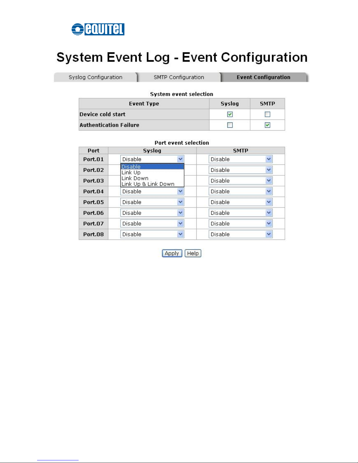
System Event Log—Event Configuration
The checkboxes and pull-down menus are not available unless the
Syslog Client Mode
on the Syslog Configuration tab and the
E-mail Alert
on the SMTP Configuration tab are
enabled first.
This tab mainly controls whether an event notification is to be sent to the
Syslog/SMTP
server. The part of
System Event Selection
controls the event notification including
Device Cold Start and Authentication Failure. With the
Syslog/SMTP
checkbox ticked,
the event log/email alert will be sent to the system log server/SMTP server respectively.
As for the part of
Port Event Selection
, port events (link up, link down, and both) can be
sent to the system log server/SMTP server by setting the trigger condition for each port
respectively.
System event selection: There are two event types—Device Cold Start and
Authentication Failure.
Device Cold Start: Tick the Syslog/SMTP checkboxes respectively to have the
system issue the event log/email alert to the system log/SMTP server when the
device executes the cold start action.
Authentication Failure: When the SNMP authentication fails, the system will
issue the event log/email alert to the system log/SMTP server respectively.
Port event selection: Each drop-down menu has four options—Disable, Link UP,
Link Down, and Link UP & Link Down. Disable means no event will be sent to the
system log/SMTP server.
Link UP: The system will issue a log message only when the link-up event of
the port occurs.
Link Down: The system will issue a log message only when the link-down event
of port occurs.
Link UP & Link Down: The system will issue a log message at the time when
port connection is link-up and link-down.
Page 58
September 2011 Ed.2.0
EQUITEL – Technical Manual N968
51
Event Configuration interface
Page 59
September 2011 Ed.2.0
EQUITEL – Technical Manual N968
52
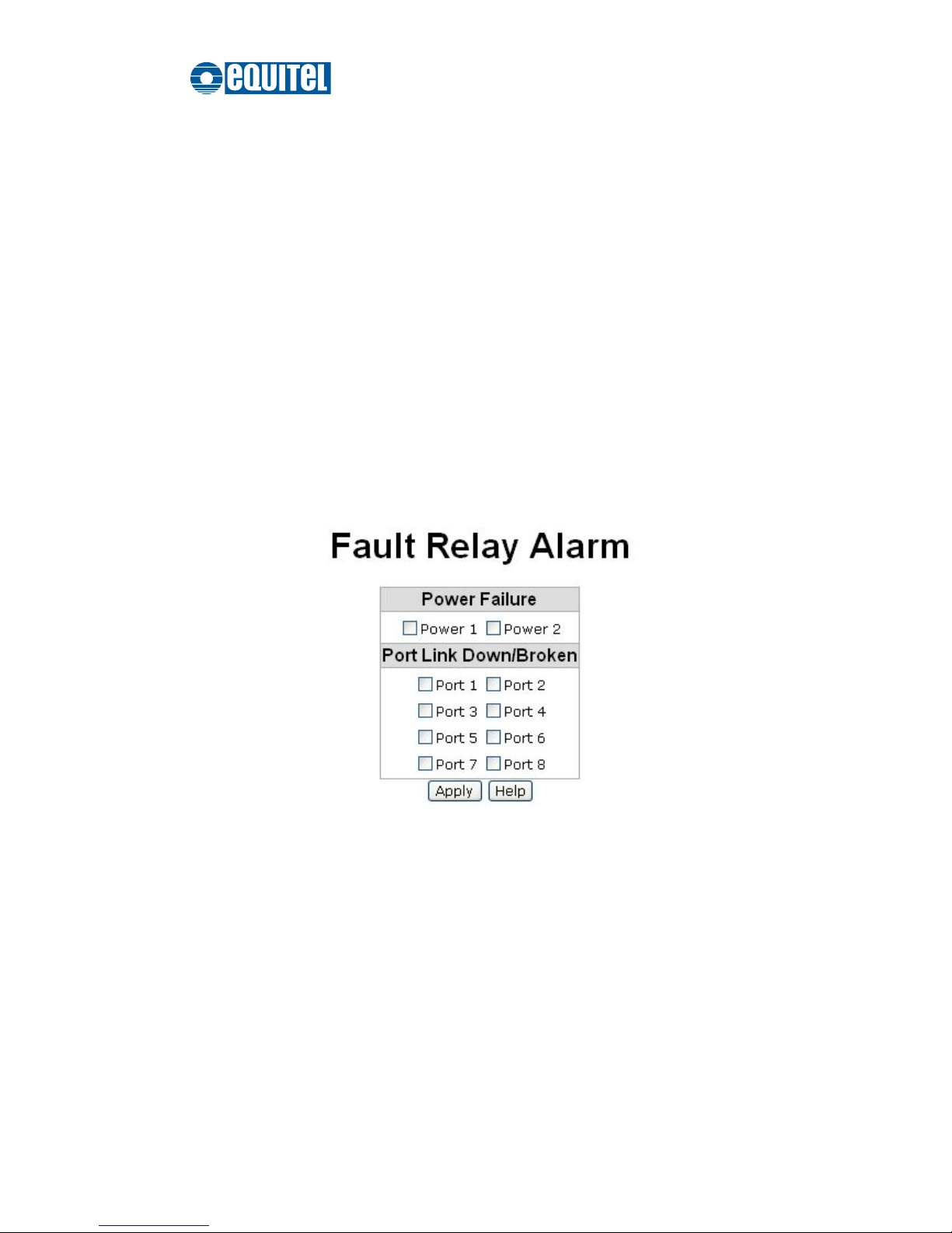
Fault Relay Alarm
The Fault Relay Alarm function provides the Power Failure and Port Link Down/Broken
detection. Tick the checkbox to enable the relay alarming function. Please refer to the
segment of ‘
Wiring the Fault Alarm Contacts
’ for the external warning device
installation.
Power Failure: With the checkbox ticked the relay device inside the industrial switch
changes its state and the FAULT LED indicator is on if a power failure occurs.
Port Link Down/Broken: With the checkbox ticked the relay device inside the
industrial switch changes its state and the FAULT LED indicator is on if the
corresponding port’s states become link down or broken.
Fault Relay Alarm interface
Page 60

September 2011 Ed.2.0
EQUITEL – Technical Manual N968
53
SNTP Configuration
SNTP (Simple Network Time Protocol) is a simplified version of NTP which is an Internet
protocol used to synchronize the clocks of computers with some time reference. Because
time usually just advances, the time on different node stations might be different. With the
communicating programs running on those devices, it would cause time to jump forward
and back, a non-desirable effect. Therefore, the switch provides comprehensive
mechanisms to access national time and frequency dissemination services, organize the
time-synchronization subnet and the local clock in each participating subnet peer.
Daylight Saving Time (DST) is the convention of advancing clocks so that afternoons
have more daylight and mornings have less. Typically clocks are adjusted forward one
hour near the start of spring and are adjusted backward in autumn.
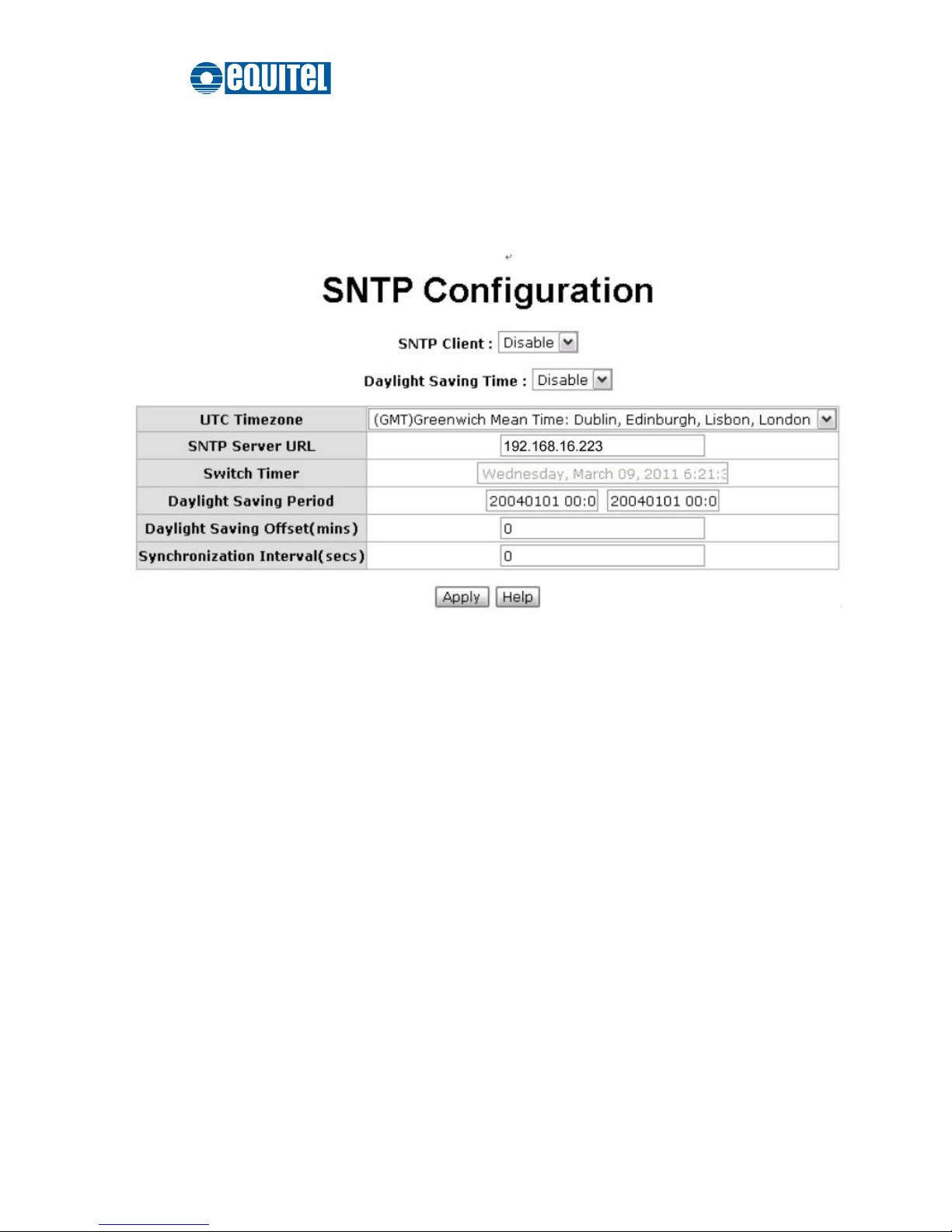
SNTP Client: Enable/disable the SNTP function to get the time from the SNTP
server.
Daylight Saving Time: This function is used to enable/disable Daylight Saving
Period and Daylight Saving Offset fields.
UTC Timezone: Set the location time zone for the switch. The following table lists
different location time zones for your reference.
Local Time Zone
Conversion from UTC
Time at 12:00 UTC
November Time Zone
- 1 hour
11 am
Oscar Time Zone
-2 hours
10 am
ADT - Atlantic Daylight
-3 hours
9 am
AST - Atlantic Standard
EDT - Eastern Daylight
-4 hours
8 am
EST - Eastern Standard
CDT - Central Daylight
-5 hours
7 am
Page 61

September 2011 Ed.2.0
EQUITEL – Technical Manual N968
54
CST - Central Standard
MDT - Mountain Daylight
-6 hours
6 am
MST - Mountain
Standard
PDT - Pacific Daylight
-7 hours
5 am
PST - Pacific Standard
ADT - Alaskan Daylight
-8 hours
4 am
ALA - Alaskan Standard
-9 hours
3 am
HAW - Hawaiian
Standard
-10 hours
2 am
Nome, Alaska
-11 hours
1 am
CET - Central European
FWT - French Winter
MET - Middle European
MEWT - Middle
European Winter
SWT - Swedish Winter
+1 hour
1 pm
EET - Eastern European,
USSR Zone 1
+2 hours
2 pm
BT - Baghdad, USSR
Zone 2
+3 hours
3 pm
ZP4 - USSR Zone 3
+4 hours
4 pm
ZP5 - USSR Zone 4
+5 hours
5 pm
ZP6 - USSR Zone 5
+6 hours
6 pm
WAST - West Australian
Standard
+7 hours
7 pm
CCT - China Coast,
+8 hours
8 pm
Page 62

September 2011 Ed.2.0
EQUITEL – Technical Manual N968
55
USSR Zone 7
JST - Japan Standard,
USSR Zone 8
+9 hours
9 pm
EAST - East Australian
Standard GST
Guam Standard, USSR
Zone 9
+10 hours
10 pm
IDLE - International Date
Line
NZST - New Zealand
Standard
NZT - New Zealand
+12 hours
Midnight
SNTP Sever URL: Specify the SNTP server IP address. You can assign a local
network time server IP address or an internet time server IP address.
Switch Timer: When the switch has successfully connected to the SNTP server
whose IP address was assigned in the field of SNTP Server URL, the current
coordinated time is displayed here.
Daylight Saving Period: Set up the start and end date/time of the daylight saving
period. Please key in the value in the format of ‘YYYYMMDD’ and ‘HH:MM’ (leave a
space between ‘YYYYMMDD’ and ‘HH:MM’).
YYYYMMDD: an eight-digit year/month/day specification.
HH:MM: a five-digit (including a colon mark) hour/minute specification.
For example, key in ‘20070701 02:00’ and ‘20071104 02:00’ in the two fields
respectively to represent that DST begins at 2:00 a.m. on March 11, 2007 and ends
at 2:00 a.m. on November 4, 2007.
Daylight Saving Offset (mins): For non-US and European countries, specify the
amount of time for day light savings. Please key in the valid figure in the range of
minute between 0 and 720, which means you can set the offset up to 12 hours.
Synchronization Interval (secs): The Synchronization Interval is used for sending
synchronizing packets periodically. Users can assign the time ranging from 64 to
1024 seconds. The “0” value displaying by default means that you disable the
Page 63
September 2011 Ed.2.0
EQUITEL – Technical Manual N968
56
auto-synchronized feature in the SNTP client mode. You can enable the feature by
filling the interval range from 64~1024 seconds.
Click Apply to have the configuration take effect.
SNTP Configuration interface
Page 64

September 2011 Ed.2.0
EQUITEL – Technical Manual N968
57
IP Security
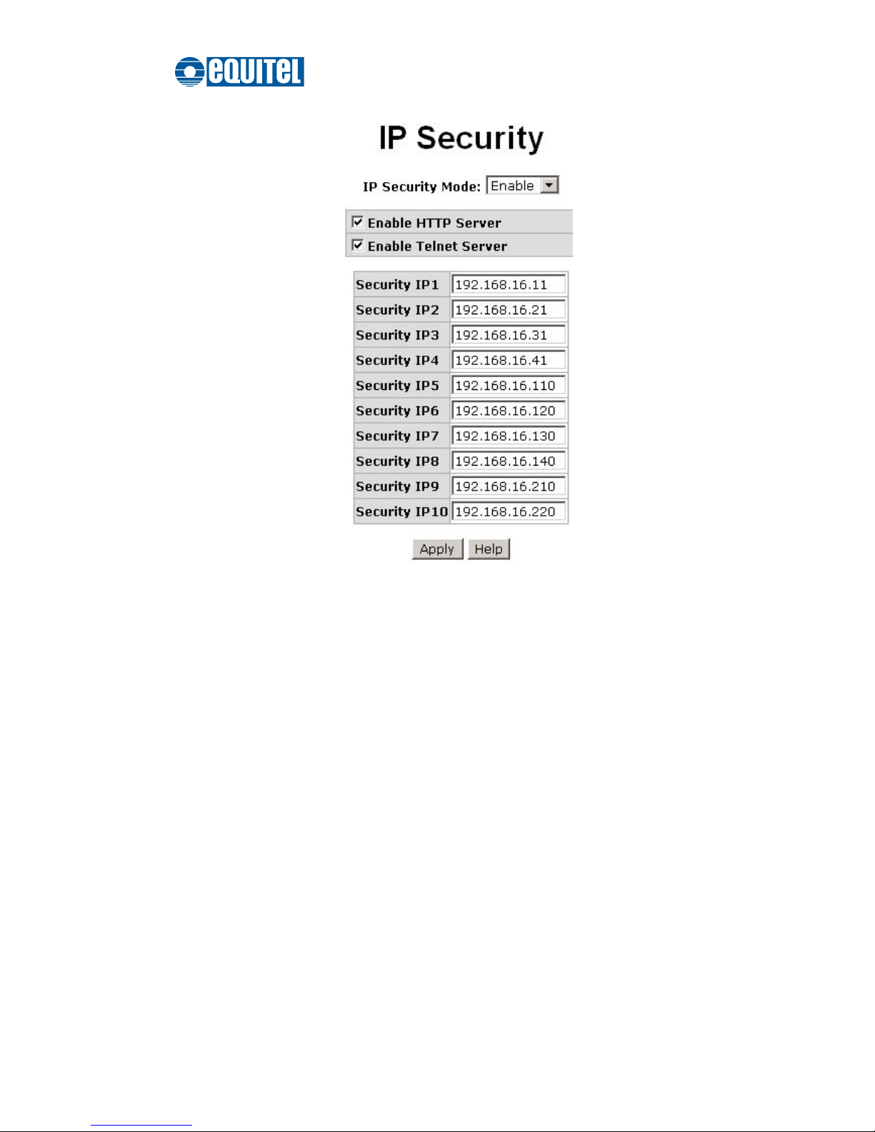
IP security function allows the user to assign up to 10 specific IP addresses that have
permission to manage the switch through the http and telnet services for securing switch
management. The purpose of giving permission to limited IP addresses is to allow only
the authorized personnel/device to do the management task on the switch.
IP Security Mode: With this selection item set in the Enable mode, the Enable
HTTP Server, Enable Telnet Server checkboxes and the ten security IP fields will
then be available. If not, those items will appear in grey.
Enable HTTP Server: With this checkbox ticked, Ethernet devices whose IP
addresses match any one of the ten IP addresses in the Security IP table will be
given permission to access this switch via the HTTP service.
Enable Telnet Server: With this checkbox ticked, Ethernet devices whose IP
addresses match any one of the ten IP addresses in the Security IP table will be
given permission to access this switch via the telnet service.
Security IP 1 ~ 10: The system allows the user to assign up to 10 specific IP
addresses for access security. Only when IP Security Mode is enabled can these
10 IP addresses access and manage the switch through the HTTP/Telnet services.
And then, click Apply to have the configuration take effect.
[NOTE]
Remember to execute the “Save Configuration” action, otherwise the new
configuration will lose when the switch powers off.
Page 65
September 2011 Ed.2.0
EQUITEL – Technical Manual N968
58
IP Security interface
Page 66
September 2011 Ed.2.0
EQUITEL – Technical Manual N968
59
User Authentication
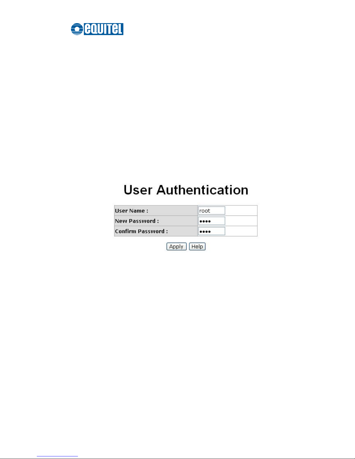
Here you can change login user name and password for management security purposes.
Admin User
User Name: The user account is root by default. Type in the User Name field with a
new name as you wish.
New Password: The password to the user account is root by default. Type in the
New Password field with a new password as you wish.
Confirm password: Type in the new password again for confirmation.
When finished, click Apply to have the configuration take effect.
User Authentication interface
Page 67

September 2011 Ed.2.0
EQUITEL – Technical Manual N968
60
Port Statistics
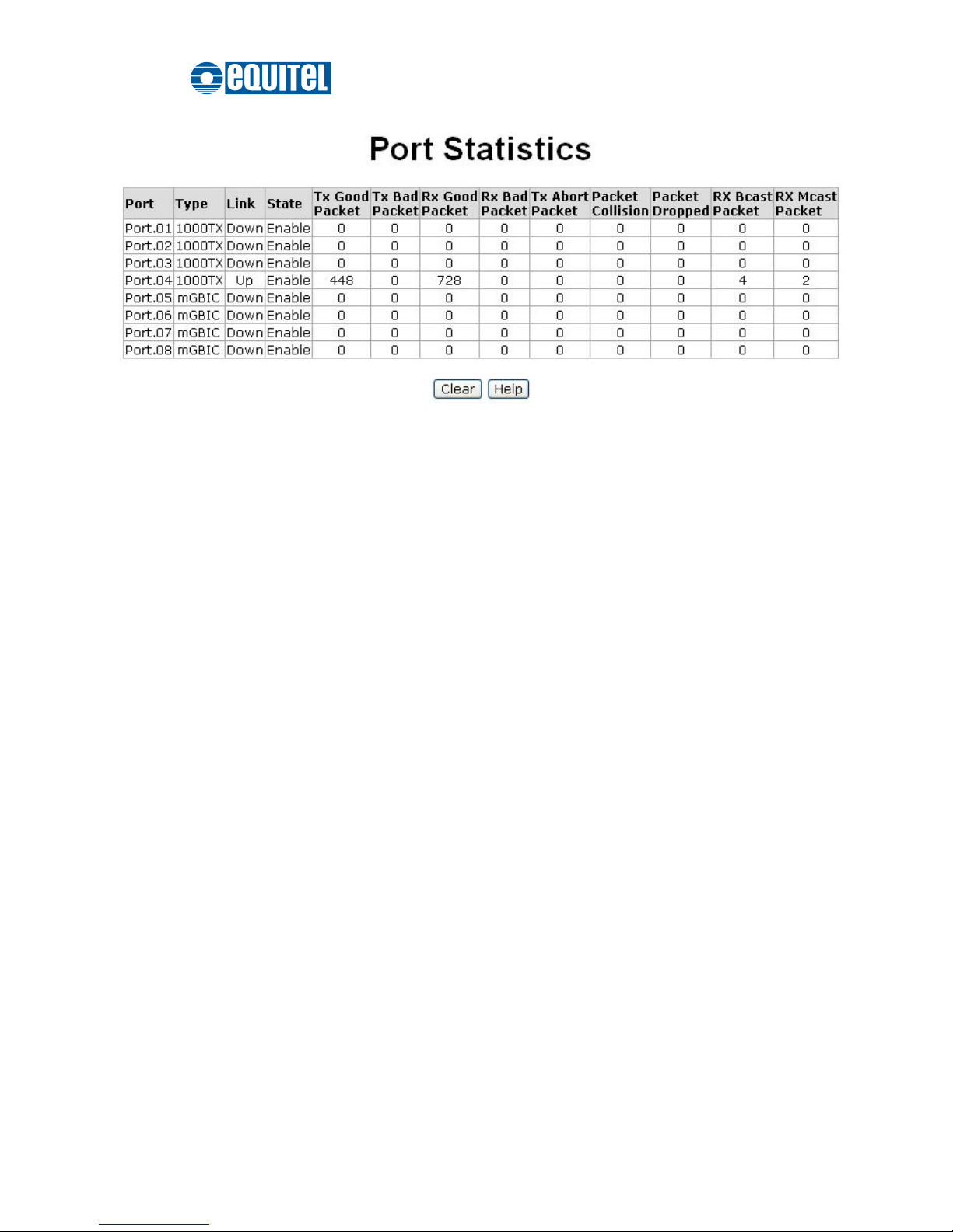
The following chart provides the current statistics information which displays the real-time
packet transfer states for each port. The user might use the information to plan and
implement the network, or check and find the problem when the collision or heavy traffic
occurs.
Port: Port number indexed.
Type: Displays the network media type of the port.
Link: The states of linking—‘Up’ or ‘Down’.
State: Displays port states set by the Port Control interface. When the state is
disabled, the port will not transmit or receive any packet.
Tx Good Packet: The counts of transmitting good packets via this port.
Tx Bad Packet: The counts of transmitting bad packets (including undersize [less
than 64 bytes], oversize, CRC Align errors, fragments and jabbers packets) via this
port.
Rx Good Packet: The counts of receiving good packets via this port.
Rx Bad Packet: The counts of receiving good packets (including undersize [less
than 64 bytes], oversize, CRC error, fragments and jabbers) via this port.
Tx Abort Packet: The counts of aborted packets while transmitting.
Packet Collision: The counts of packet collision.
Packet Dropped: The counts of dropped packets.
Rx Bcast Packet: The counts of broadcast packets.
Rx Mcast Packet: The counts of multicast packets.
Click the Clear button to clean all counts.
Page 68
September 2011 Ed.2.0
EQUITEL – Technical Manual N968
61
Port Statistics interface
Page 69

September 2011 Ed.2.0
EQUITEL – Technical Manual N968
62
Port Control
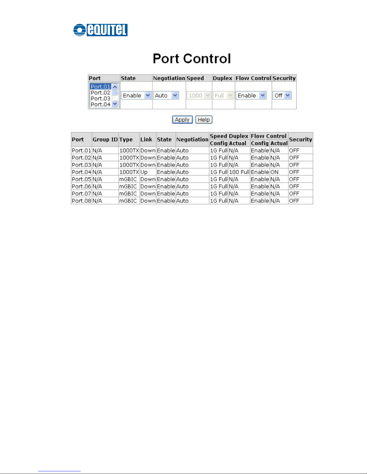
In Port Control you can configure the parameters of the connection for each port.
Port: Scroll up/down the scroll bar and click on the port number to choose a
particular port to be configured.
State: Enable/disable the port. If the port state is set on ‘Disable’, the port will not be
able to receive or transmit any packet.
Negotiation: Options include Auto and Force. With this parameter set on Auto, the
speed and duplex fields display in grey, which means the port are negotiated
automatically. When you set it on Force, you have to set the speed and duplex mode
manually by clicking the pull-down menus of the Speed and Duplex fields.
Speed: It is available for selecting when the Negotiation field is set on Force. When
the Negotiation field is set on Auto, this field becomes a read-only field displaying in
grey.
Duplex: It is available for selecting when the Negotiation field is set on Force. When
the Negotiation field is set on Auto, this field becomes a read-only field displaying in
grey.
Flow Control: Whether the receiving node sends feedback to the sending node is
determined by this item. With this item enabled, if the input data rate of the receiving
device exceeds, the receiving device will send a PAUSE frame which halts the
transmission of the sender for a specified period of time. With this item disabled, the
receiving device will drop the packets it is unable to process.
Security: When the Security selection is set as ‘On’, any access from the device
which connects to this port will be blocked unless the MAC address of the device is
included in the static MAC address table.
Click Apply to have the configuration take effect.
Page 70
September 2011 Ed.2.0
EQUITEL – Technical Manual N968
63
Port Control interface
Page 71

September 2011 Ed.2.0
EQUITEL – Technical Manual N968
64
Port Trunk
Port trunking is the combination of several ports or network cables to expand the
connection speed beyond the limits of any one single port or network cable. Link
Aggregation Control Protocol (LACP), which is a protocol running on layer 2, provides
a standardized means in accordance with IEEE 802.3ad to bundle several physical
ports together to form a single logical channel. All the ports within the logical channel
or so-called logical aggregator work at the same connection speed and LACP
operation requires full-duplex mode.
Aggregator Setting
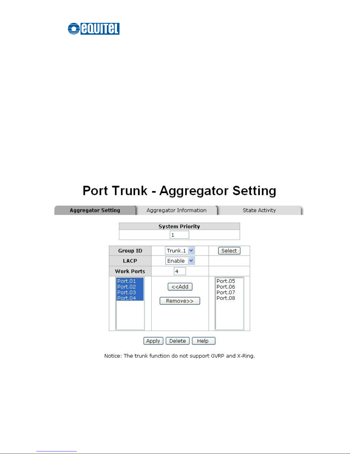
Please read the instrutions below to make an LACP or non-LACP trunk group.
System Priority: A value which is used to identify the controlling switch of an
LACP link system. The switch with the lower value has the higher system priority
and is selected as the controlling end, which controls port priorities, of the LACP
link system.
Group ID:
There are four trunk groups to be selected. Assign the group ID to the
particular trunk group.
LACP: Click the pull-down menu to enable/disable LACP for the trunk group. With
LACP enabled, a port which joins an LACP trunk group has to make an
agreement with its member ports first. Please notice that a trunk group, including
member ports split between two switches, has to enable the LACP function of the
two switches. When disabled, the trunk group is a static trunk group. The
advantage of having the LACP disabled is that a port joins the trunk group without
any handshaking with its member ports; but member ports won’t know that they
should be aggregated together to form a logic trunk group.
Work Ports: This field allows the user to type in the total number of active ports
up to four.With a LACP trunk group employed, for example you assign four ports
to be the members of a trunk group whose Work Ports field is set as two the
excessive ports will be standby/redundant ports and can be aggregated instead of
working ports that fail. As for the static trunk group (non-LACP), the number of
Page 72
September 2011 Ed.2.0
EQUITEL – Technical Manual N968
65
work ports must equal the total number of the group member ports.
The system allows a maximum of four ports to be aggregated in a trunk group.
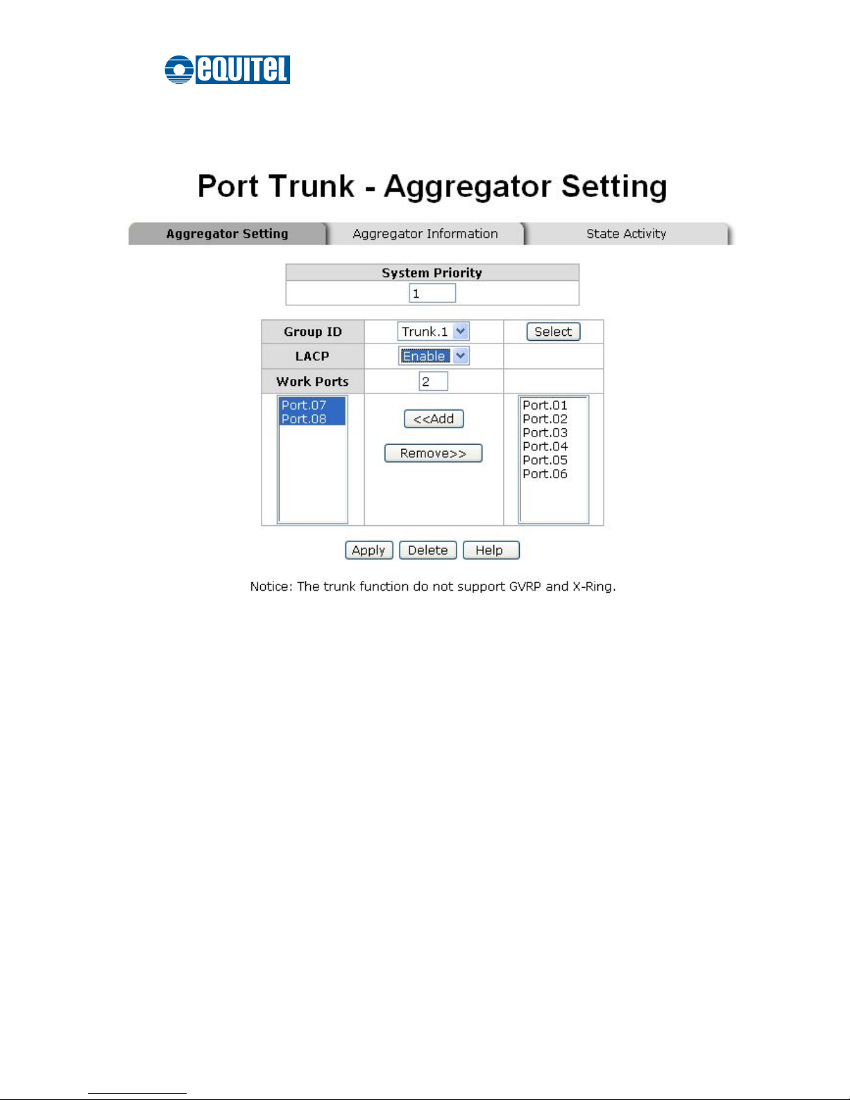
Having configured the parameters above, highlight the ports in the right list box to
join the trunk group. Click the Add button and the ports highlighted in the right list
box will be shifted to the left list box. To remove unwanted ports, select the ports in
the left list box and click the Remove button.
When LACP enabled, you can configure LACP Active/Passive states for each
member port on the State Activity tab.
When finished, click Apply to take the configuration take effect.
To remove a trunk group, select the Group ID by clicking the pull-down menu
labeled as ‘Group ID’ and click then click the Delete button.
Port Trunk—Aggregator Setting interface (four ports are added to the left field with LACP enabled)
Page 73
September 2011 Ed.2.0
EQUITEL – Technical Manual N968
66
Aggregator Information
LACP Disabled
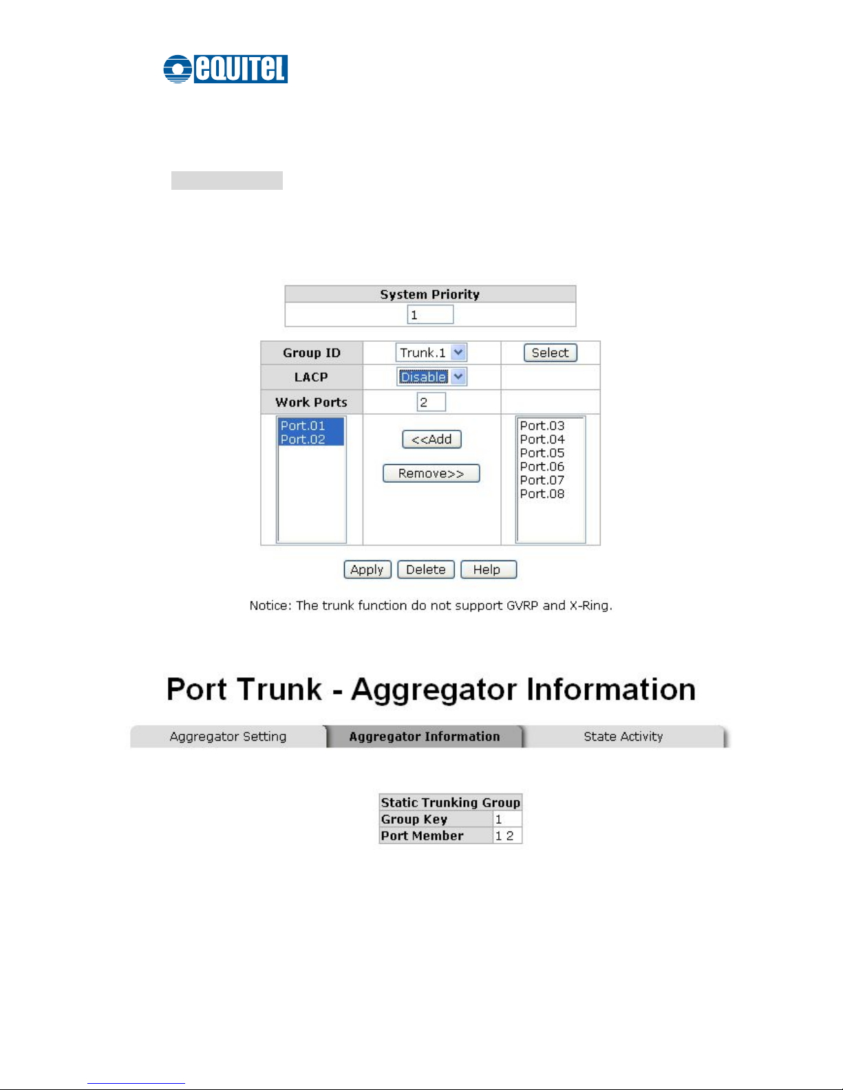
Having configured the aggregator setting with LACP disabled, you can check the static
trunk group information on the Aggregator Information tab.
Assigning 2 ports to a trunk group with LACP disabled
Static Trunking Group Information tab
Group Key: This is a read-only field that displays the trunk group ID.
Port Member: This is a read-only field that displays the members of the static
trunk group.
Page 74
September 2011 Ed.2.0
EQUITEL – Technical Manual N968
67
LACP Enabled
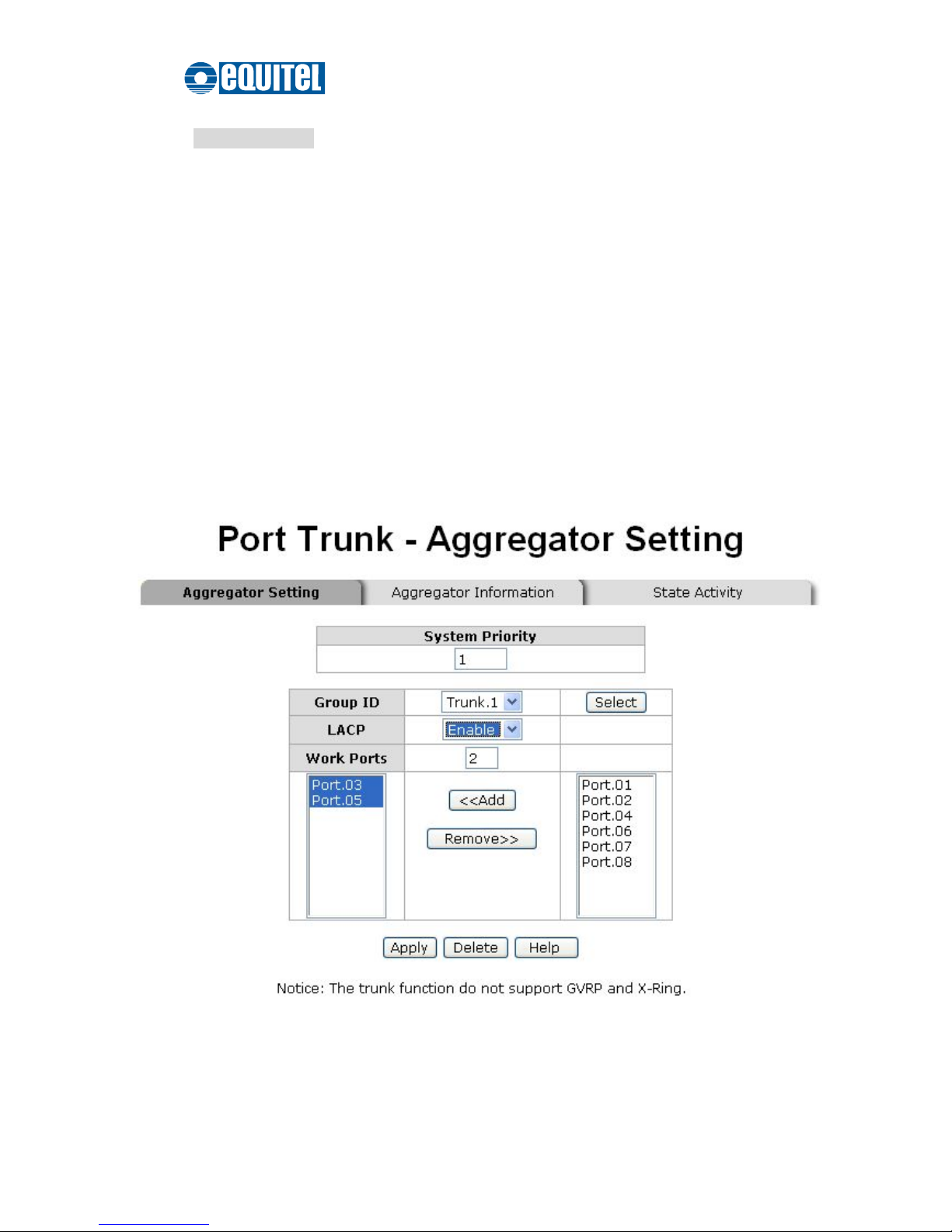
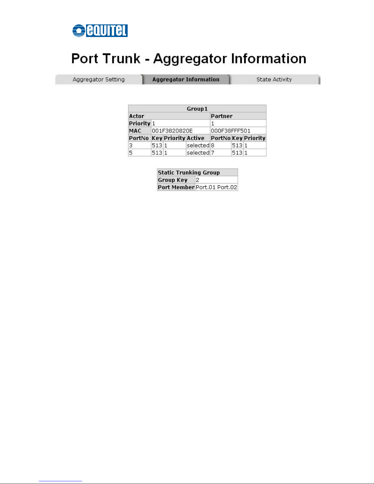
Having configured the aggregator setting with LACP enabled, you can check the
trunking group information between two switches on the Aggregator Information tab.
Configuration for Switch 1
1. Set System Priority of the trunk group. The field displays with ‘1’ by default.
2. Select a trunk group ID by clicking the pull-down menu.
3. Enable LACP.
4. Include the member ports by highlighting the ports in the right list box and then
click the Add button. Note the number in the Work Ports field changes
automatically depending on how many ports you have selected.
Switch 1 configuration interface
Page 75
September 2011 Ed.2.0
EQUITEL – Technical Manual N968
68
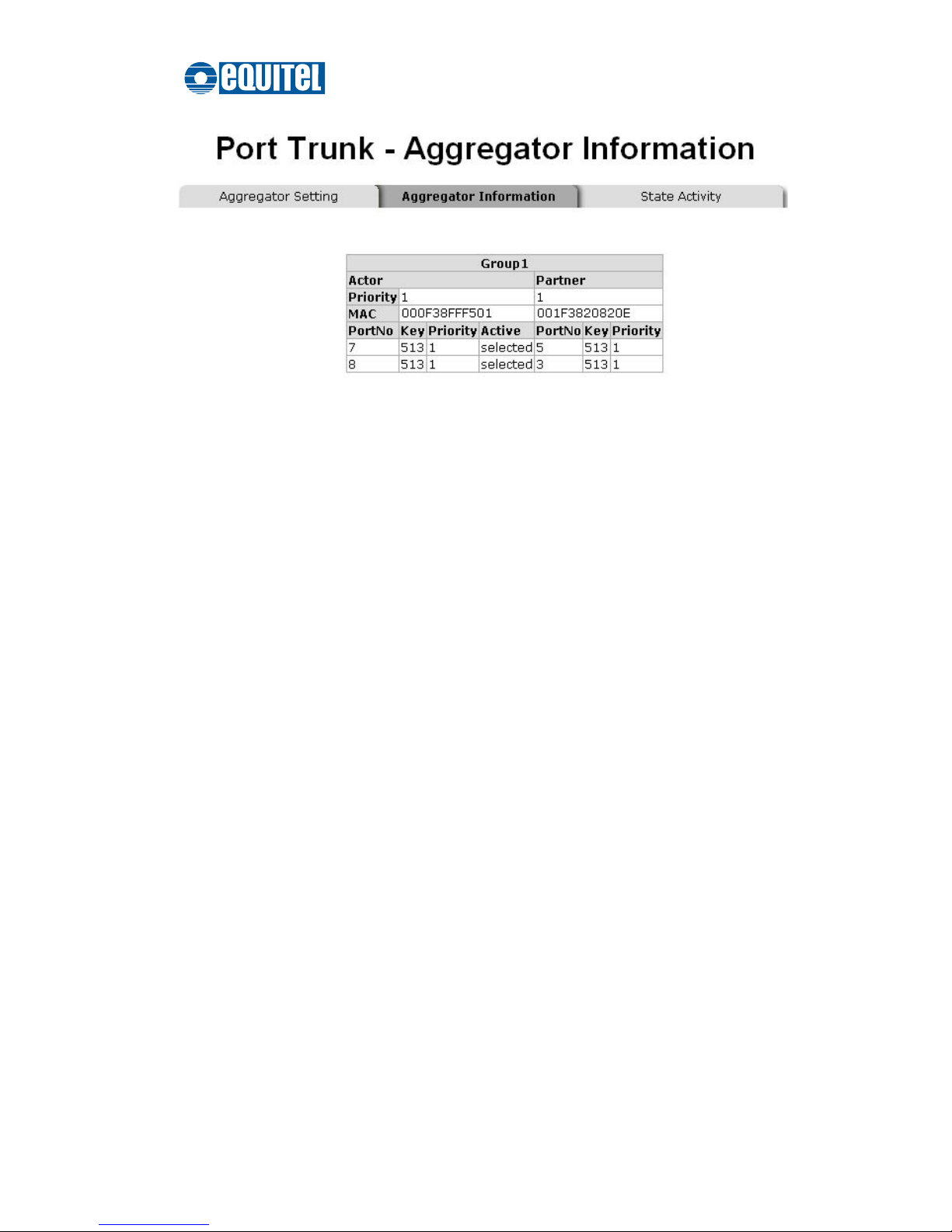
Aggregation Information of Switch 1
5. Click on the Aggregator Information tab to check the trunked group information
as the illustration shown above after the two switches configured.
Page 76
September 2011 Ed.2.0
EQUITEL – Technical Manual N968
69
Configuration for Switch 2
Switch 2 configuration interface
1. Set System Priority of the trunk group. The field displays with ‘1’ by default.
2. Select a trunk group ID by clicking the pull-down menu.
3. Enable LACP.
4. Include the member ports by highlighting the ports in the right list box and then
click the Add button. Note the number in the Work Ports field changes
automatically depending on how many ports you have selected.
Page 77
September 2011 Ed.2.0
EQUITEL – Technical Manual N968
70
Aggregation Information of Switch 2
5. Click on the Aggregator Information tab to check the trunked group information
as the illustration shown above after the two switches configured.
Page 78
September 2011 Ed.2.0
EQUITEL – Technical Manual N968
71
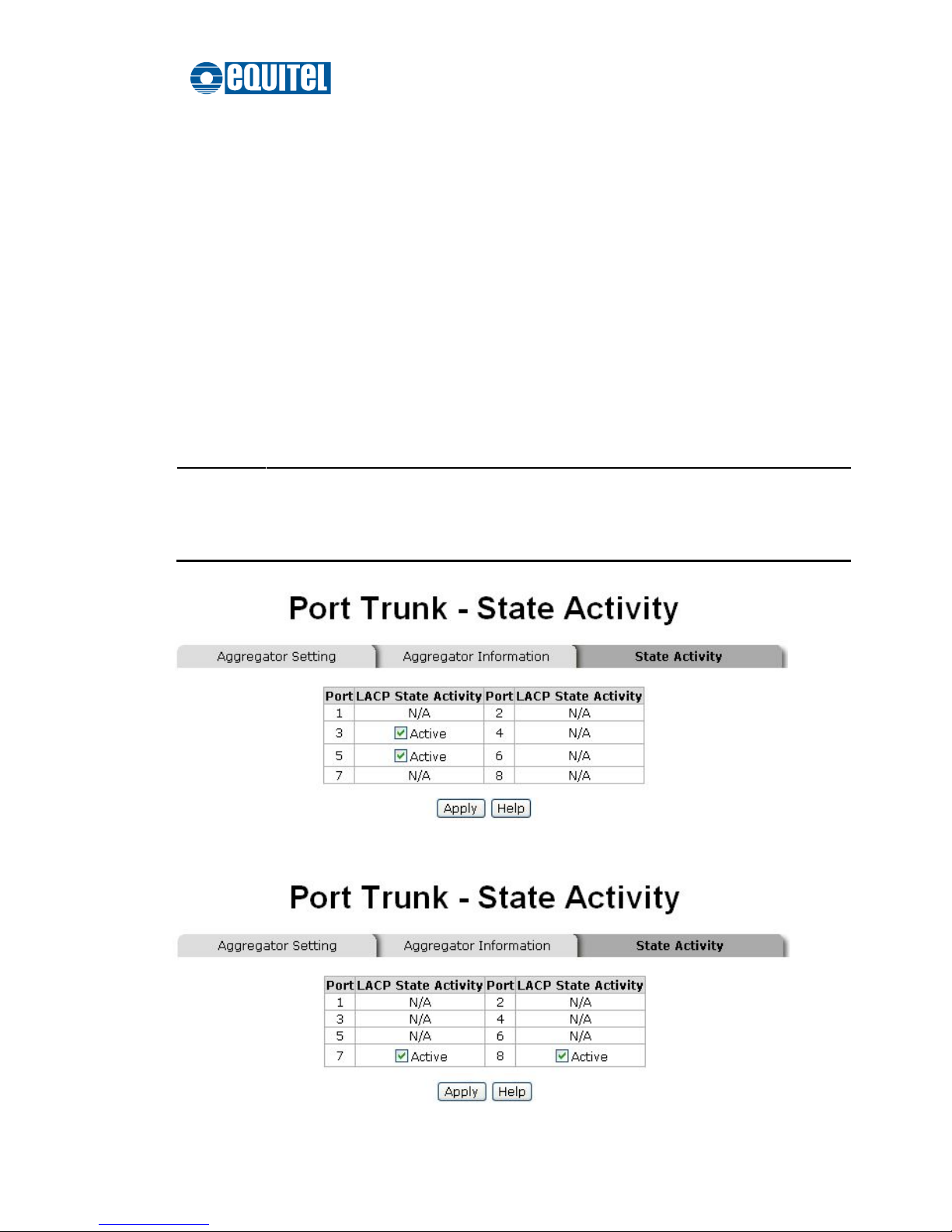
State Activity
Having configured the LACP aggregator on the
Aggregator Setting
tab, you may want
to change the state activity for the members of the LACP trunk group. You can tick/untick
the checkbox beside the state label. If you remove the tick mark of the corresponding port
and click the Apply button, the port state activity will change to
Passive
.
Active: The port automatically sends LACP protocol packets.
Passive: The port does not actively send LACP protocol packets. It responds only if
it receives LACP protocol packets from the opposite device.
[NOTE]
A link having two passive LACP nodes will not perform dynamic LACP
trunk because both ports are waiting for an LACP protocol packet from the
opposite device.
State Activity of Switch 1
Page 79

September 2011 Ed.2.0
EQUITEL – Technical Manual N968
72
State Activity of Switch 2
Page 80
September 2011 Ed.2.0
EQUITEL – Technical Manual N968
73
Port Mirroring
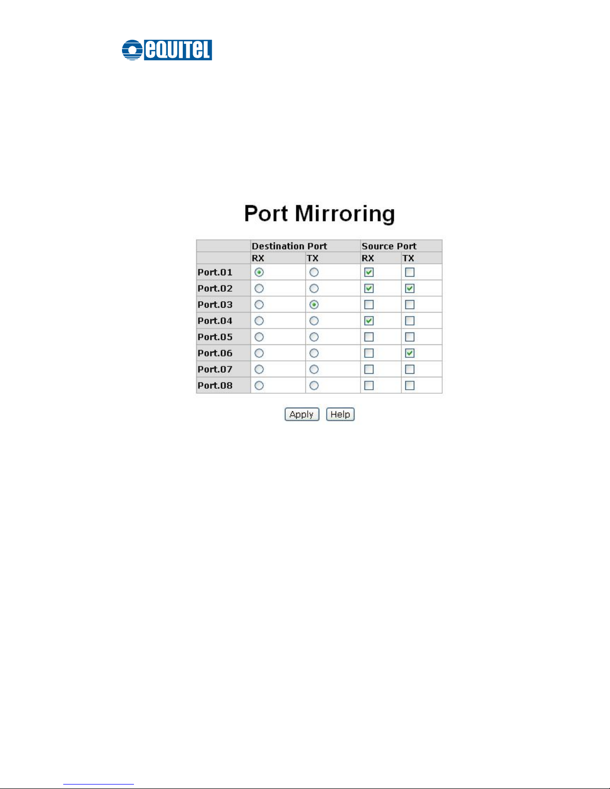
Port Mirroring is a method for monitoring of network traffic on switched networks. Traffic
through ports can be monitored by one specific port, which means traffic going in or out
the monitored (source) ports will be duplicated into the mirroring (destination) port.
Port Mirroring interface
Destination Port: Select one port to be the destination (mirroring) port for
monitoring both RX and TX traffic coming from the source port. Or, select two ports
for monitoring RX traffic and TX traffic respectively. Users can forward the traffic
captured by the mirroring port to the packet analyzer like Netxray for further
analyses.
Source Port: Tick the checkbox to monitor the corresponding port. All monitored
port traffic will be copied to the mirroring (destination) port. Users can select multiple
source ports by ticking the RX or TX checkboxes.
When finished, click the Apply button.
Page 81
September 2011 Ed.2.0
EQUITEL – Technical Manual N968
74
Rate Limiting
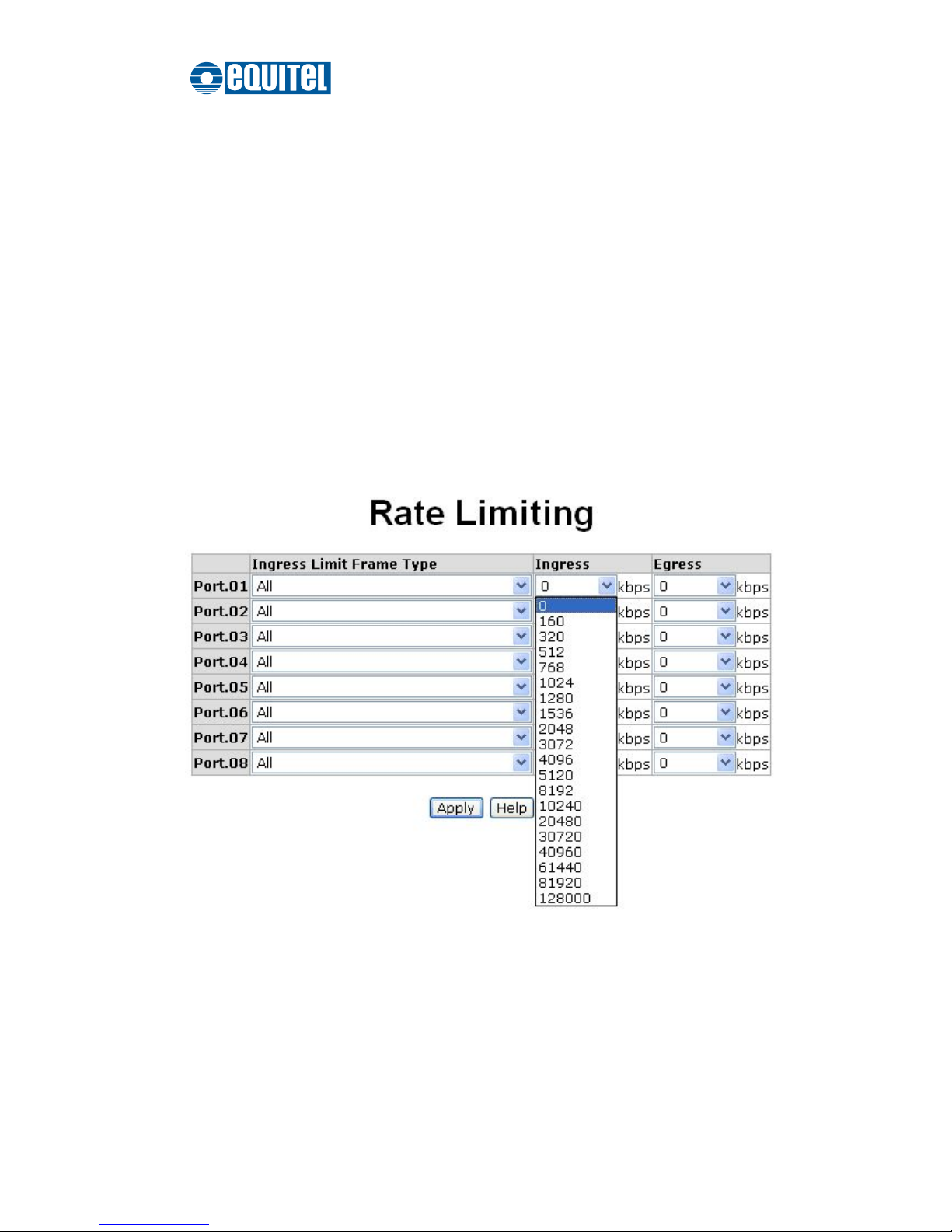
You can respectively configure the ingress limitation type and ingress/egress rate for
each port.
Ingress Limit Frame Type: Select the limit type for ingress frames. Four options are
available as follows:
All
Broadcast/Multicast/Flooded Unicast
Broadcast/Multicast
Broadcast only
The egress rate will limit all types of frame.
Rate Limiting interface
Click the Ingress/Egress pull-down menus to select the bandwidth limit.
When finished, click Apply to have the configuration take effect.
Page 82
September 2011 Ed.2.0
EQUITEL – Technical Manual N968
75
DMI
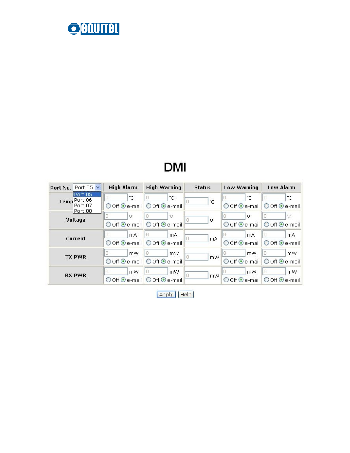
The DMI (Diagnostic Monitoring Interface) is developed for monitoring temperature,
voltage, current, transmitting power and receiving power for SFP (Mini-GBIC) ports. If
the real detected values, such as temperature, voltage, current etc., of the respective
ports reach the threshold of the connected transceiver, the system will shut down the
device or send e-mail to notify the related staff. The recipients can be specified via the
SMTP configuration. Please refer to the System Event Log—SMTP Configuration
section.
DMI interface
Port No.: Click the pull-down menu to select a particular SFP port to display its
information and define reaction options.
Temperature: The fields showing values measured in degrees Celsius. Click the
radio button labeled as ‘Off’ to shut down the device or the other one labeled as
‘e-mail’ to send e-mail for notifications when the port temperature reaches the
threshold.
Voltage: The fields showing values measured in voltages. Click the radio button
labeled as ‘Off’ to shut down the device or the other one labeled as ‘e-mail’ to
Page 83

September 2011 Ed.2.0
EQUITEL – Technical Manual N968
76
send e-mail for notifications when the port voltage reaches the threshold.
Current: The fields showing values measured in milliamperes. Click the radio
button labeled as ‘Off’ to shut down the device or the other one labeled as ‘e-mail’
to send e-mail for notifications when the port current reaches the threshold.
TX PWR: The fields showing values measured in milliwatts. Click the radio button
labeled as ‘Off’ to shut down the device or the other one labeled as ‘e-mail’ to
send e-mail for notifications when the port transmitting power reaches the
threshold.
RX PWR: The fields showing values measured in milliwatts. Click the radio button
labeled as ‘Off’ to shut down the device or the other one labeled as ‘e-mail’ to
send e-mail for notifications when the port receiving power reaches the threshold.
Page 84
September 2011 Ed.2.0
EQUITEL – Technical Manual N968
77
VLAN Configuration
A Virtual LAN (VLAN) is a logical network grouping that limits the broadcast domain,
which allows you to isolate network traffic. Therefore only the members of the same
VLAN will receive traffic from the ones among the same VLAN. Basically, creating a
VLAN on a switch is logically equivalent of reconnecting a group of network devices to
another Layer 2 switch; however, all the network devices are still plugged into the
same switch physically.
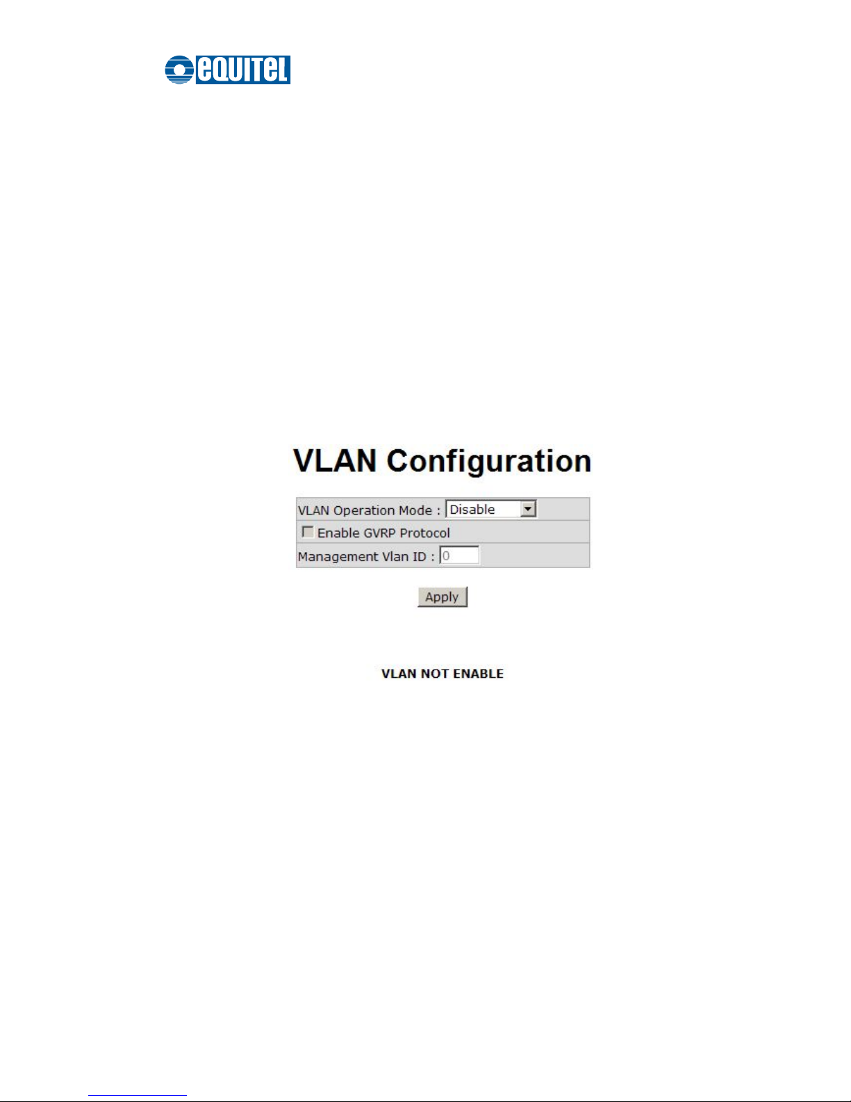
This switch supports Port-based and 802.1Q (tagged-based) VLAN. Please read the
following instructions to configure the appropriate type of VLAN for your need.
VLAN Configuration interface
Page 85
September 2011 Ed.2.0
EQUITEL – Technical Manual N968
78
Port-based VLAN
A port-based VLAN normally consists of its members—ports, which means the VLAN
is created by grouping the selected ports. This method provides the convenience for
users to configure a simple VLAN easily without complicated steps. Packets can go
among only members of the same VLAN group. Note all unselected ports are treated
as belonging to another single VLAN that is, technically, a single broadcast domain. If
the port-based VLAN is enabled, the VLAN-tagging will be ignored. Port-based VLAN
allows the user to create separate VLANs to limit the unnecessary packet flooding;
however, for the purpose of sharing resource, a single port called a common port can
belongs to different VLANs, which all the member devices (ports) in different VLANs
have the permission to access the common port while they still cannot communicate
with each other in different VLANs.
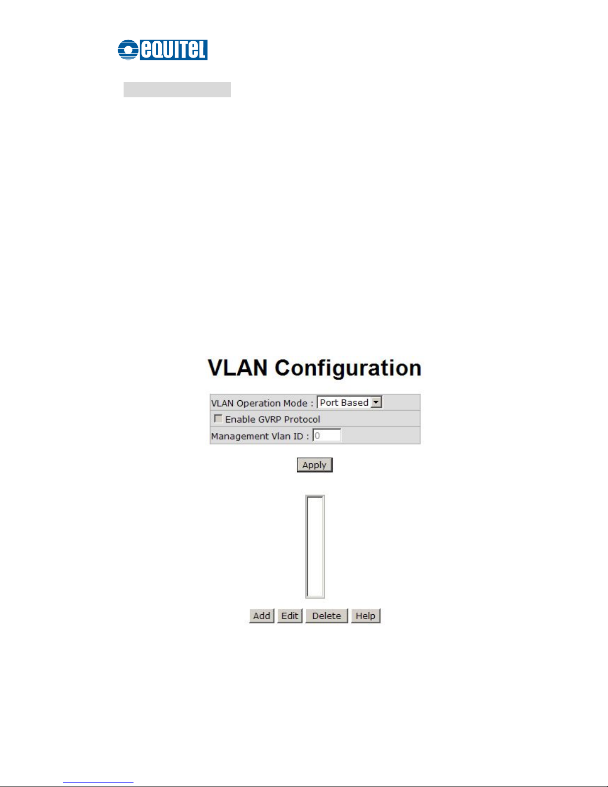
VLAN – Port Based interface
Click the pull-down menu to select
Port Based
and then click the Apply button to
set the VLAN operation mode on
Port Based
.
Page 86
September 2011 Ed.2.0
EQUITEL – Technical Manual N968
79
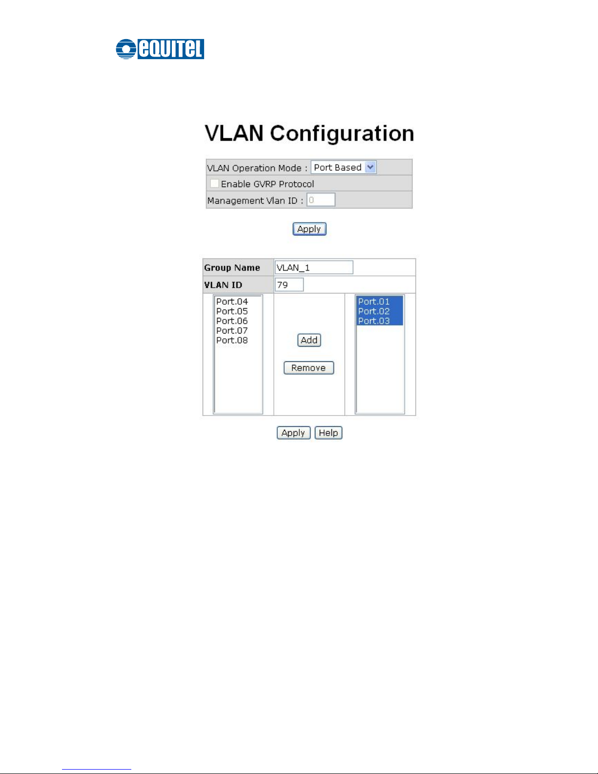
With the VLAN operation mode selected, click Add to create a new VLAN group.
Add a Port Based VLAN
Enter the group name and VLAN ID. Select the port number available in the left list
box, and click the Add button to move the highlighted ports to the right list box. Or
you can select any of the ports listed in the right field and click Remove to remove
port(s) from the VLAN.
When finished, click Apply to have the VLAN configuration take effect.
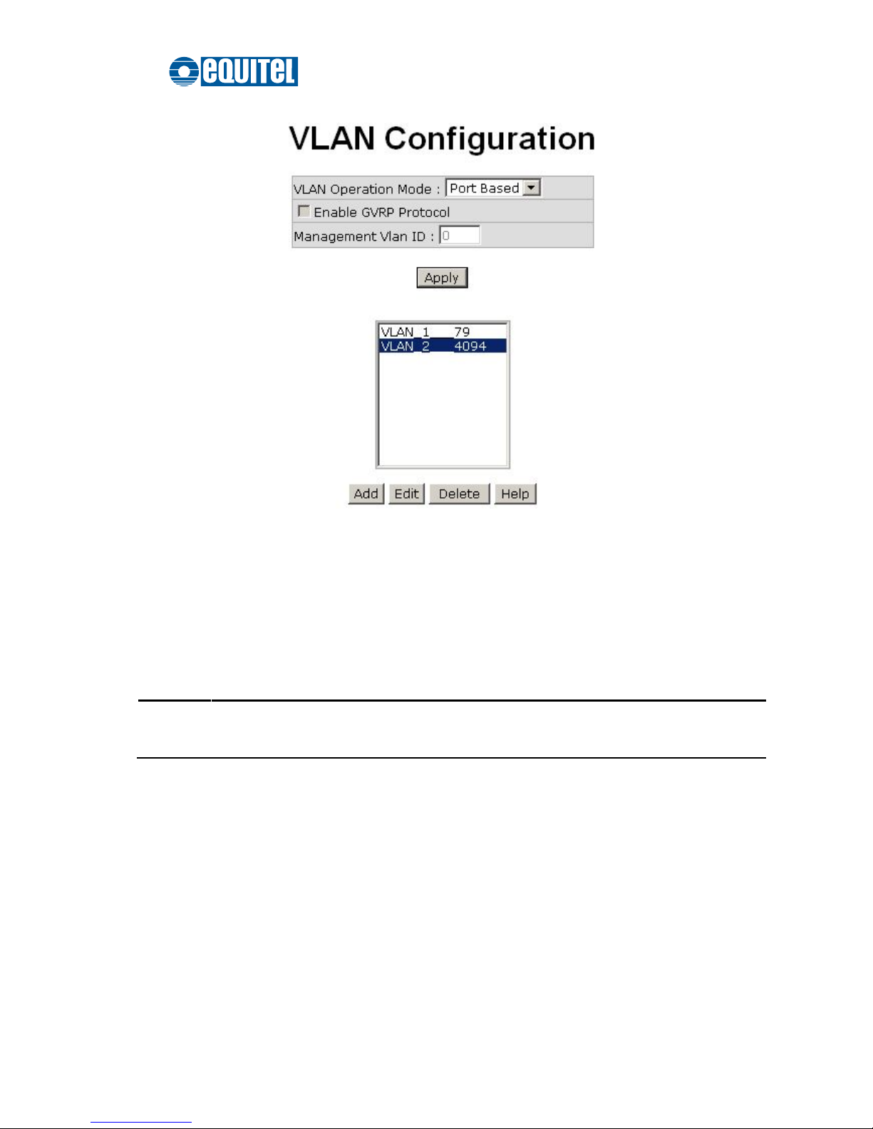
And then you will see the VLAN list shows up.
Page 87
September 2011 Ed.2.0
EQUITEL – Technical Manual N968
80
Edit/Delete Port Based VLAN
With the VLAN list box showing up, select VLAN(s) and click the Delete button to
get rid of the VLAN(s).
Highlight a VLAN and click the Edit button to change group name, VLAN ID, or to
add/remove the members of the existing VLAN group.
[NOTE]
Remember to execute the “Save Configuration” action, otherwise the new
configuration will lose when the switch powers off.
Page 88

September 2011 Ed.2.0
EQUITEL – Technical Manual N968
81
802.1Q VLAN
When the VLAN operation mode is set on 802.1Q, all ports on the switch belong to the
default VLAN of VID 1, which means they logically are regarded as members of the
same broadcast domain. The valid VLAN ID is in the range of number between 1 and
4094. The amount of VLAN groups is up to 256 including the default VLAN that cannot
be deleted.
GVRP (GARP VLAN Registration Protocol) is a protocol that facilitates control of
VLANs within a larger network. GVRP conforms to the IEEE 802.1Q specification,
which defines a method of tagging frames with VLAN configuration data. This allows
network devices to dynamically exchange VLAN configuration information with other
devices. For example, with GVRP enabled, the switches are able to automatically
exchange the information of their VLAN database. Therefore, the user needn’t
manually configure the link type. The packets belonging to the same VLAN can
communicate across switches.
Each member port of 802.1Q is on either an Access Link (VLAN-tagged) or a Trunk
Link (no VLAN-tagged). All frames on an Access Link carry no VLAN identification.
Conversely, all frames on a Trunk Link are VLAN-tagged. Besides, there is the third
mode—Hybrid. A Hybrid Link can carry both VLAN-tagged frames and untagged
frames. A single port is supposed to belong to a particular VLAN group, except it is on
a Trunk/Hybrid Link.
The technique of 802.1Q tagging inserts a 4-byte tag, including VLAN ID of the
destination port—PVID, in the frame. With the combination of Access/Trunk/Hybrid
Links, the communication across switches also can make the packet sent through
tagged and untagged ports.
Page 89

September 2011 Ed.2.0
EQUITEL – Technical Manual N968
82
802.1Q Configuration
Please follow the instructions below to configure the 802.1Q VLAN.
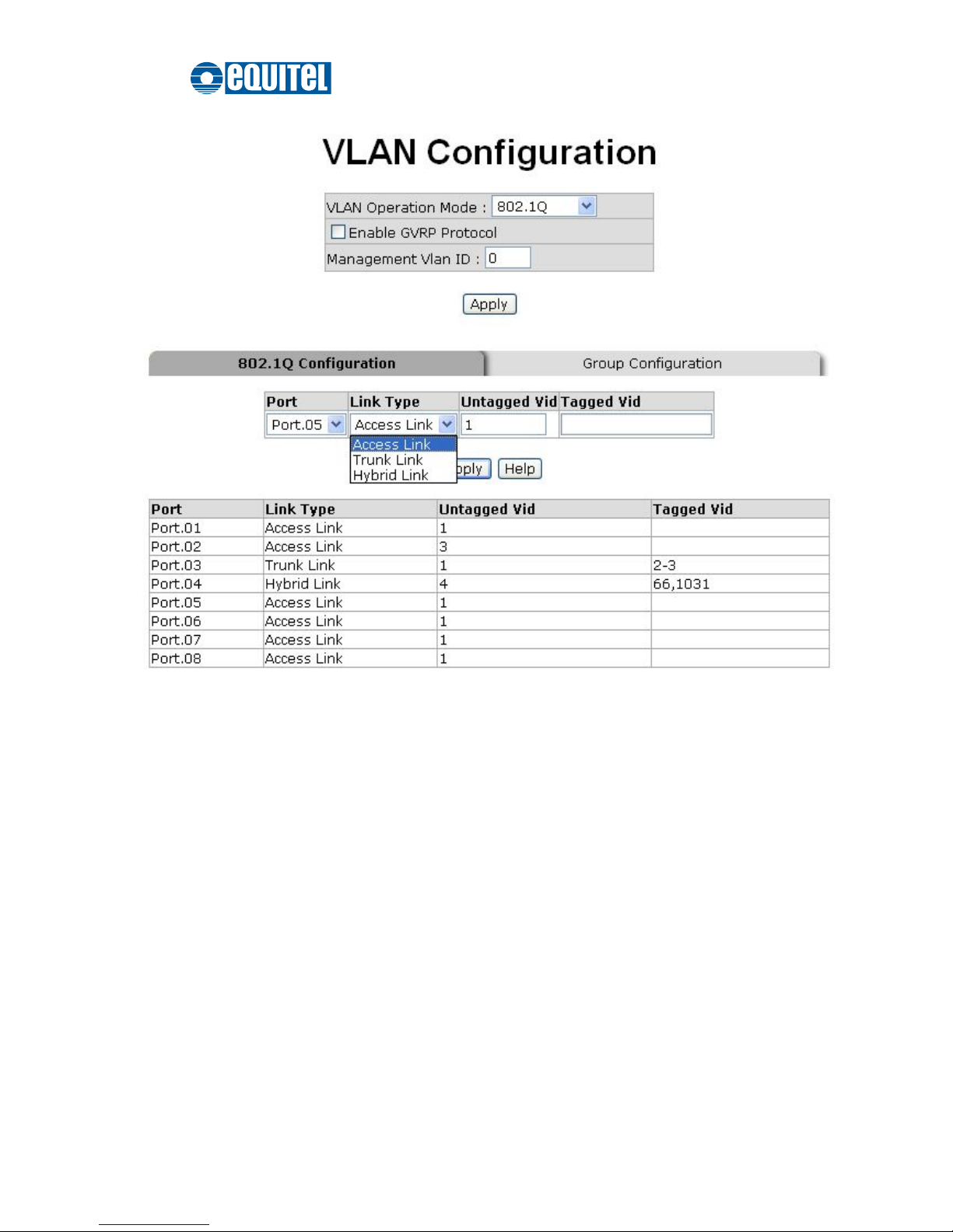
Click the pull-down menu to select
802.1Q
and click Apply to configure the VLAN
Operation Mode on
802.1Q
.
Enable GVRP Protocol: Tick this checkbox to enable GVRP protocol. This
checkbox is available while the VLAN Operation Mode is set on 802.1Q.
Management VLAN ID: Only the VLAN members, whose Untagged VID (PVID)
equals to the value specified in this field, have permission to access the switch. The
default value is ‘0’ that means this limit is not enabled (all members in different
VLANs can access this switch).
After you have configured the three parameters, click the Apply button right beneath
this area to finish creating an 802.1Q VLAN.
Page 90
September 2011 Ed.2.0
EQUITEL – Technical Manual N968
83
802.1Q VLAN interface
On the 802.1Q Configuration tab, click the Port pull-down menu to select a port you
want to configure within the VLAN.
Link Type: Three options are available. Click the pull-down menu to select the link
type.
Access Link: A segment which provides the link path for one or more stations
to the VLAN-aware device like switches. An Access Port (untagged port)
connecting to the access link has an untagged VID (also called PVID). After an
untagged frame gets into the access port, the switch inserts a four-byte tag in
the frame. The contents of the last 12-bit of the tag is the untagged VID. When
this frame is sent out through any of the access ports of the same PVID, the
switch will remove the tag from the frame to recover it to what it was. Those
ports of the same untagged VID are regarded as the same VLAN group
members.
Page 91

September 2011 Ed.2.0
EQUITEL – Technical Manual N968
84
[NOTE]
Because the access port doesn’t have an understanding of tagged frame, the
field of Tagged VID is not available.
Trunk Link: A segment which provides the link path for one or more
VLAN-aware devices. A Trunk Port connecting to the trunk link has an
understanding of tagged frame, which is used for communications across
VLANs. Which frames of the specified VIDs will be forwarded depends on the
values filled in the Tagged VID field. Please insert a comma between two VIDs.
[NOTE]
1. A trunk port doesn’t insert tags into an untagged frame, and therefore the
untagged VID field is not available.
2. It’s not necessary to type ‘1’ in the tagged VID field. The trunk port will
forward the frames of VLAN 1.
3. The trunk port has to be connected to a trunk/hybrid port of the other switch.
Both the tagged VID of the two ports have to be the same.
Hybrid Link: A segment which consists of Access and Trunk links. The hybrid
port has both the features of the access and trunk ports. A hybrid port has a
PVID belonging to a particular VLAN, and also forwards the specified
tagged-frames for the purpose of VLAN communications between switches.
[NOTE]
1. It’s not necessary to type ‘1’ in the tagged VID field. The hybrid port will
forward the frames of VLAN 1.
2. The trunk port has to be connected to a trunk/hybrid port of the other switch.
Both the tagged VID of the two ports have to be the same.
Untagged Vid: This field is available when the Link Type pull-down menu is set on
Access Link or Hybrid Link. Assign a number in the range between 1 and 4094.
Tagged Vid:
This field is available when the Link Type pull-down menu is set on
Trunk Link or Hybrid Link. Assign a number in the range between 1 and 4094.
Click the Apply button on the tab to have the port configuration take effect.
Page 92
September 2011 Ed.2.0
EQUITEL – Technical Manual N968
85
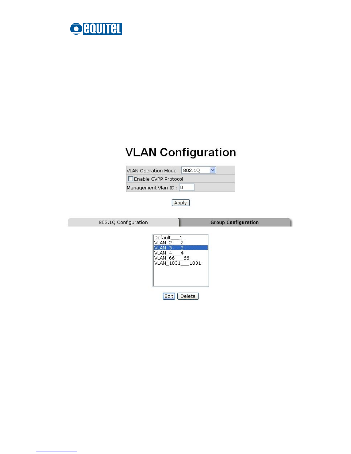
And then you can see the link type, untagged VID, and tagged VID information of
each port shown in the table on the screen.
Group Configuration
Edit the existing VLAN Groups.
Click the Group Configuration tab.
Select a VLAN group in the list box and click the Edit button.
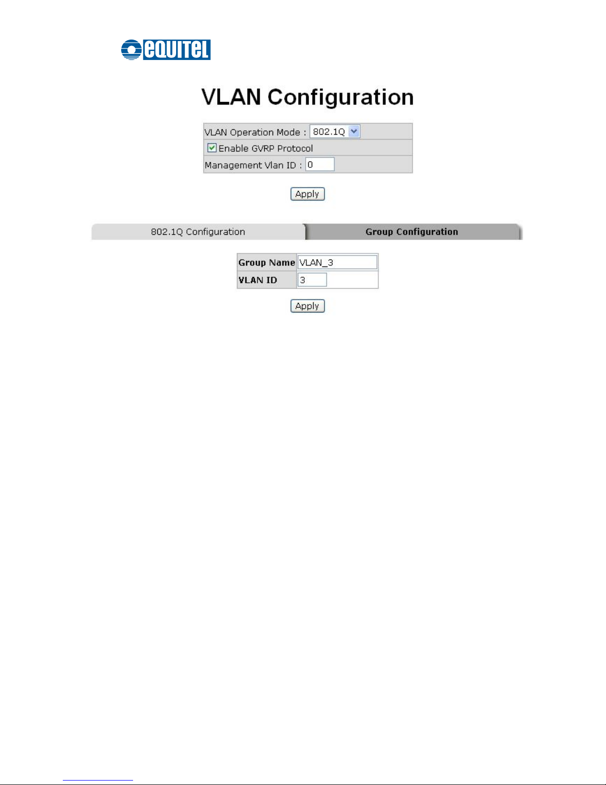
Group Configuration interface
After clicking the Edit button, you can change group name and VLAN ID of the
selected VLAN group.
Page 93
September 2011 Ed.2.0
EQUITEL – Technical Manual N968
86
Group Configuration interface
When finished, click Apply to have the modification take effect.
Page 94

September 2011 Ed.2.0
EQUITEL – Technical Manual N968
87
Rapid Spanning Tree
The Rapid Spanning Tree Protocol (RSTP) is an evolution of the Spanning Tree Protocol
providing for faster spanning tree convergence after a topology change. The system also
supports STP and will auto-detect the connected device running STP or RSTP.
RSTP System Configuration
This tab allows users to configure parameters for RSTP and displays the spanning tree
information of the root bridge.
RSTP mode: Click the pull-down menu to enable the RSTP function.
Priority (0-61440): The switch with the lowest numerical value has the highest
priority and will be selected as the root device. If the value is changed, users must
reboot the switch. Note the value specified in this field must be a multiple of 4096
according to the protocol rule.
Max Age (6-40): Enter the time in seconds between 6 and 40 for which the switch
waits to attempt to save its configuration.
Hello Time (1-10): Enter the time in seconds between 1 and 10 that controls the
switch to send out the BPDU packet to check current states of RSTP.
Forward Delay Time (4-30): Enter the time in seconds between 4 and 30 that a port
spends changing from its learning and listening state to the forwarding state.
When finished, click the Apply button to have the configuration take effect.
[NOTE]
Follow the rule below to configure Max Age, Hello Time, and Forward Delay
Time parameters.
2 x (Forward Delay Time value –1) > = Max Age value >= 2 x (Hello Time
value +1)
Root Bridge Information
The column fields give the current bridge information for the switch.
Page 95

September 2011 Ed.2.0
EQUITEL – Technical Manual N968
88
Bridge ID: This field displays the bridge ID by showing the MAC address of this
switch.
Root Priority: This field displays the numerical value indicating bridge priority of the
switch. Generally, the switch with the lowest numerical value in the network is set as
the root bridge.
Root Port: This field indicates which port is connecting to the root bridge. When the
switch is set as the root bridge, the word ‘Root’ shows here.
Root Path Cost: This field displays the path cost between the switch’s root port and
the designated port of the root bridge. Path cost is a value to each port typically
based on rules described as part of 802.1d. For the root bridge this is zero. For all
other bridges, it is the sum of the port path costs on the least cost path to the root
bridge.
Max Age: Displays the configured aging time of the switch.
Hellow Time: Displays the configured Hellow Time.
Forward Delay: Displays the configured forward delay time.
Page 96
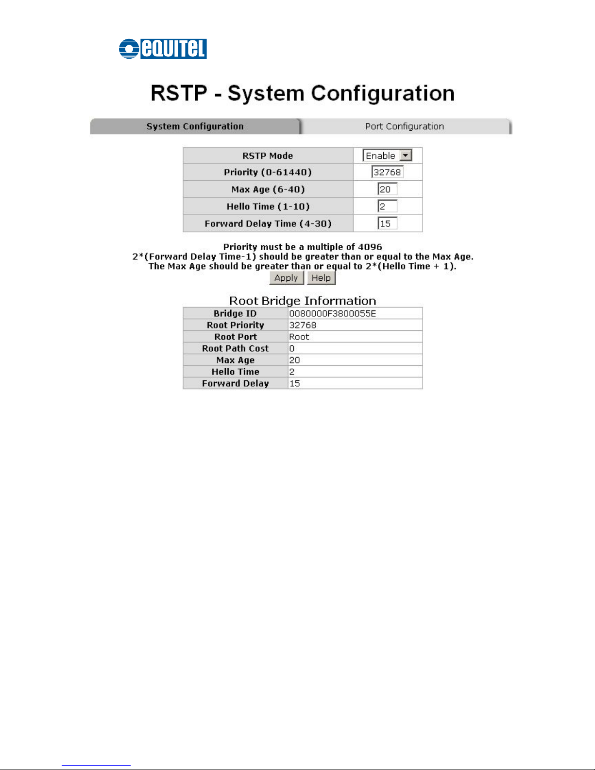
September 2011 Ed.2.0
EQUITEL – Technical Manual N968
89
RSTP System Configuration interface
Page 97

September 2011 Ed.2.0
EQUITEL – Technical Manual N968
90
Port Configuration
This tab offers the interface for RSTP port configuration where you can assign
parameters to each port. The rapid spanning tree protocol will have the port with the
higher priority in forwarding state and block other ports to make certain that there is no
loop in the LAN.
Scroll the list box to select a port for configuration.
Path Cost: The path cost can be managed. Enter a number in the range of 1 to
200,000,000.
Priority: Port Poriority. Give the value to decide which port should be blocked by
setting its priority. Enter a number between 0 and 240. The entered value must be a
multiple of 16.
Admin P2P: The rapid state transitions possible within RSTP are dependent upon
whether the port concerned can only be connected to exactly another bridge (i.e. it is
served by a point-to-point LAN segment), or can be connected to two or more
bridges (i.e. it is served by a shared medium LAN segment). This function allows the
P2P states of the link to be manipulated administratively. True means the port is
regarded as a point-to-point link. False means the port is regarded as a shared link.
Auto means the link type is determined by the auto-negotiation between the two
peers.
Admin Edge: The port directly connected to an end station is known as an edge port
that won’t create bridging loop in the network. To configure the port as an edge port,
set the port to “True” state.
Admin Non Stp: Configure whether the port includes the STP mathematic
calculation. True means not to include the STP mathematic calculation. False
means the STP mathematic calculation is included.
When finished, click Apply to have the configure take effect.
Page 98
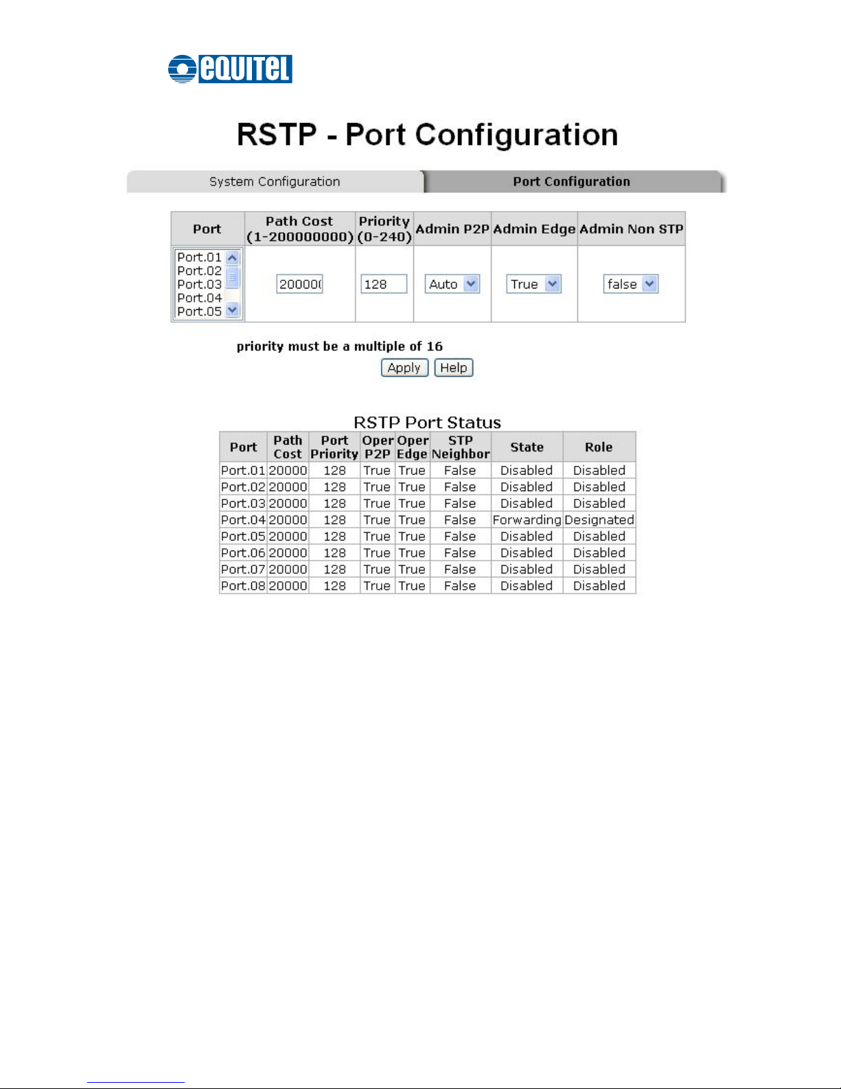
September 2011 Ed.2.0
EQUITEL – Technical Manual N968
91
RSTP Port Configuration interface
Page 99

September 2011 Ed.2.0
EQUITEL – Technical Manual N968
92
SNMP Configuration
Simple Network Management Protocol (SNMP) is the protocol developed to manage
nodes (servers, workstations, routers, switches and hubs etc.) on an IP network. SNMP
enables network administrators to manage network performance, find and solve network
problems, and plan for network growth. Network management systems (NMS) learn of
problems by receiving traps or change notices from network devices implementing
SNMP.
System Configuration
This tab allows users to define new community strings and remove the unwanted
community strings for authentication purposes. With adding a new community string, you
should also specify the type of access permission and the agent mode.
String: Enter the community string in the field as a password for authentication.
RO: Read only. With this radio button selected, the community string is given
the read-only permission for the MIB objects.
RW: Read/write. With this radio button selected, the community string is given
the read/write permission for the MIB objects.
Click Add to finish adding a new community string.
To remove a specific community string, select the community string shows in the
list box and click Remove. The strings of Public_RO and Private_RW are default
strings. You can remove them but after resetting the switch to default, the two
strings show up again.
Agent Mode:
Click one of the radio buttons to select the SNMP version that the
community string will use. And then click Change to ensure the selected SNMP
version mode is changed.
Page 100
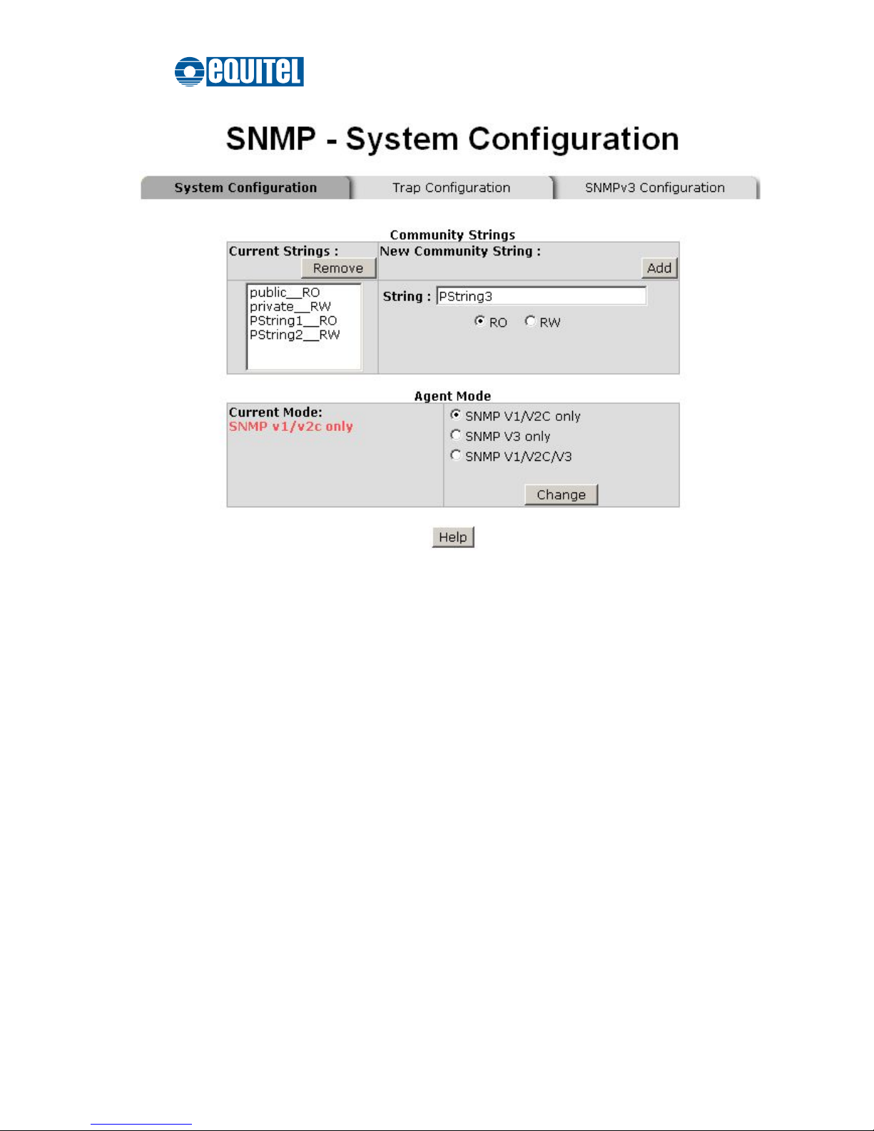
September 2011 Ed.2.0
EQUITEL – Technical Manual N968
93
SNMP System Configuration interface
 Loading...