

Page 1
Operation Manual
For
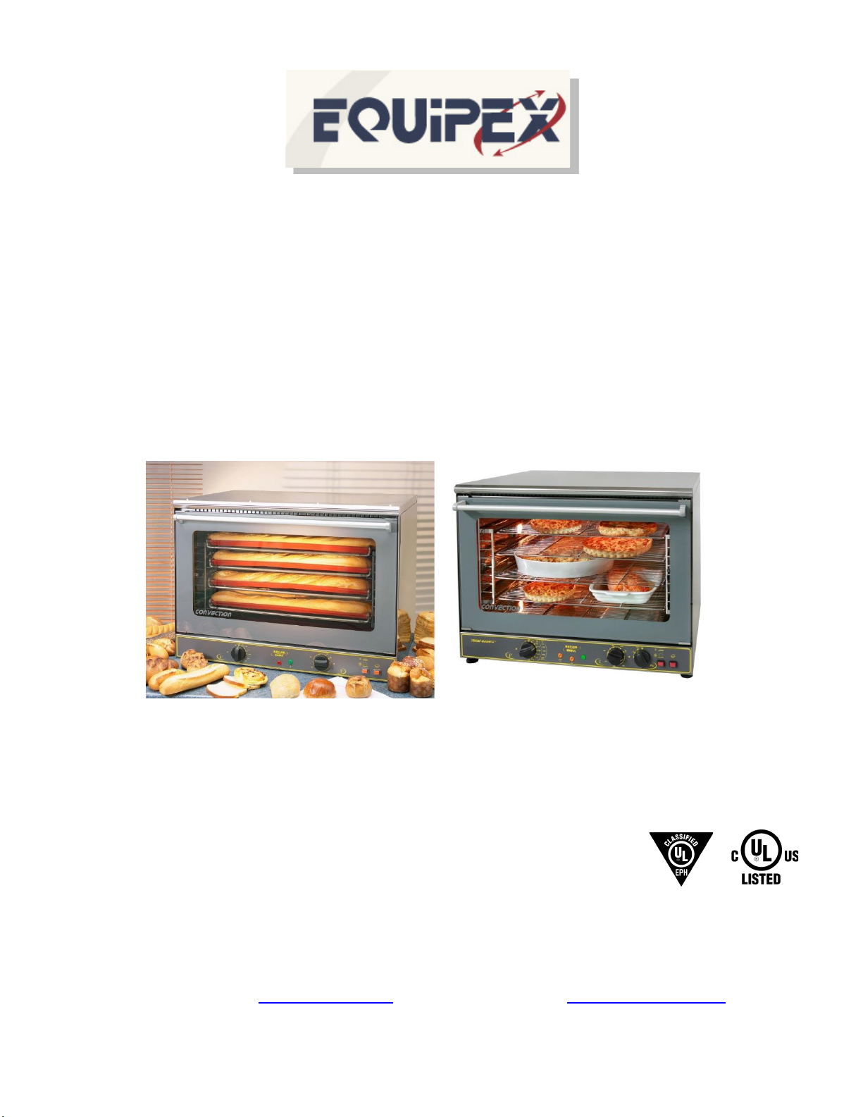
Full Size Convection Oven
FC-100, FC-103, FC-100 G, FC-103 G
100 Niantic Avenue – Suite 104 Providence, Rhode Island 02907 U.S.A.
Tel: (401) 273-3300 Fax: (401) 273-3328
Website: www.equipex.com e-mail: [email protected]
5/13/20
Page 2

IMPORTANT SAFEGUARDS
When using electrical appliances, basic safety precautions should always be followed, including the
following:
1. Read all the instructions before use.
2. Do not touch hot surfaces; use handles or knobs.
3. To avoid electric shock, do not immerse the power cord, or any part of the unit, in any liquid.
4. Close supervision is necessary when any appliance is used, especially around children.
5. Unplug appliance from the electrical outlet when not in use, and before cleaning. Allow appliance to
cool before installing or removing any parts or accessories, and before cleaning.
6. Do not operate any appliance with a damaged cord or plug, or if appliance should sustain damage, or
malfunction in any way. In this event, return appliance to the nearest authorized service facility for
examination, repair or adjustment.
7. The use of accessories and/or attachments not recommended by the appliance manufacturer may
cause injury or damage to the appliance, and may void your warranty.
8. Do not use outdoors.
9. Do not allow the power cord to hang over the edge of a table or counter, or to be exposed to hot
surfaces, as damage may occur.
10. Do not place appliance on or near a burner, or in a heated oven.
11. To disconnect an appliance, first turn all controls to the ‘off’ position then unplug the power cord from
the wall outlet.
12. Do not use appliance other than for its intended use.
13. The warmer must be plugged into a dedicated circuit of the proper ratings.
14. SAVE THESE INSTRUCTIONS FOR LATER USE!
Page 3

INTRODUCTION
The Roller Grill by Equipex Full Size Convection Ovens — Models FC-100, FC-103,
FC100 G and FC103 G, are uniquely designed to offer quality baking and cooking, with
the “G” series also adding broiling and finishing. These ovens are constructed of food
service quality stainless steel and are equipped with a rear mounted reversing blower
motor and convection heating element. The ovens have a momentary switch for the
manually controlled steam feature and another switch to select full or half fan speed. The
ovens are thermostatically controlled up to 570°F and include a 120-minute timer.
Indicator lights show when the oven is on and when the element(s) is(are) heating, in
addition to two interior lights which operate when the oven is turned on. All models
are equipped with four (4) wire shelves and will accommodate up to four full size
sheet pans (pans not included). Oven air is constantly refreshed, helping to ensure
flavors and tastes are not transferred in the oven between products, allowing several
different dishes to be cooked at the same time. The unit is protected from voltage
spikes and surges by three external fuses located under the rear cover.
The “G” models ha ve all the same features at the standard models, in addi tion to four
(4) top mounted infrared elements that operate at over 1800F when activated. The
“G” model s have a mode switc h to sel ect this feature. When the “G” mode is
activated, the top infrared elements are energized, while the fan continues to circulate
hot air to the lower shelves. In this way, foods on the lower shelves continue
baking/cooking, while the other foods are finished or broiled on the upper shelf.
Specifications:
Model Electrical NEMA Plug
FC-100 208/240V, 1PH, 6KW, 25/29 Amps 6-50P
FC-103 208/240V, 3PH, 6KW, 15/18 Amps Cord only
FC-100 G 208/240V, 1PH, 6KW (Convection) 6-50P
4.8KW (Broiling), 25/29 Amps
FC-103 G 208/240V, 1PH, 6KW (Convection) Cord only
4.8KW (Broiling), 15/18 Amps
INSTALLATION
Initial Set-up
Before operating your Equipex Convection Oven, remove all plastic film covering the unit. Failure
to do so may result in melted plastic damaging external parts, which is not covered under warranty.
Clean the unit with warm soapy water using a clean cloth or sponge. The racks and rack holders may
be removed and washed in a pot sink or dishwasher. DO NOT place the unit in a damp area or near
steam sources. Make sure the exterior back cover is not blocked, especially the steam vent. Maintain
four inches clearance at the rear, and at least two inches at each side and top of the oven. Do not
place anything on the oven top. It is mandatory to install the four-inch legs supplied with the oven
Page 4

before operating. If you wish to use the steam feature, connect the cold-water supply using a ¾ inch
NPT connector (not supplied), to the inlet at the rear back left corner of the oven, under the rear
enclosure. Turn on the water supply and check for leaks. Connect the oven to the proper dedicated
circuit. Congratulations, your oven is now ready for use!
OPERATION
Preheating
To preheat the convection oven, select the temperature by rotating the thermostat knob clockwise to
the desired temperature setting and then turn the timer knob to the right to at least 20 minutes, or turn
it left to the “constant” on position, designated by the hand symbol. For “G” models, turn the mode
switch to the convection setting, designated by the circle around a fan symbol. A green light will turn
on indicating power, and an orange light will turn on until the heat reaches the set point and then turn
off. It will take 20 minutes to reach saturation temperature with the steel retaining heat during opening
and closing the oven door.
Convection Cooking
This mode uses the rear heating element. For convection cooking or baking, once the oven is
preheated to the desired temperature, turn the timer knob to the right to the desired time setting, or to
the left to the continuous setting indicated by the hand symbol. You can choose to run the convection
motor at full or half speed, by pressing the button below the indicator which shows the switch pressed
in for low speed, and left out for high speed. Low speed is typically used for cooking more delicate
products. During operation the motor will spin in one direction, free spin for 30 seconds to slow down
and then spin for two more minutes in the opposite direction, repeatedly. This ensures the convection
air flow over and around the product is even and consistent, avoiding hot or cold spots possible with
a single direction fan. If using the timer, when the time has expired the timer bell will ding, and the
oven motor and heating element(s) will turn off. The internal timer board will continue to chirp for
several seconds after the oven shuts off as an additional notification of the time expiring. The
continuous setting will allow the oven to run until it is manually turned off. If the oven door is opened
during operation, the motor will shut off to preserve the heat in the oven chamber.
Steam Feature
This feature is typically used at the beginning of the baking cycle to create a perfect crust on products
such as bread. Pressing the momentary switch located beneath the rain cloud symbol will release a
burst of water onto the turbine fan, only after the internal temperature has reached or surpassed 200°F
and the fan is spinning. If the button is pressed when either of these conditions have not been met,
the oven will remember the request and then initiate the function. Moisture not absorbed by the
products will vent through the steam outlet located at the rear of the oven.
Broiling and Finishing
For the “G” models, four quartz tubes are mounted in the top of the oven. This mode is selected by
turning the mode switch to the second position indicated by a fan with triangles over it and setting the
temperature and timer as above. If broiling, preheat the oven first; if finishing, no preheat is necessary.
Page 5
Defrosting
The “G” models offer a fan only position, indicated by the fan alone symbol. This mode can be used
to run the motor, independent of heat, for the purpose of defrosting products more quickly using the
convection airflow.
CLEANING
WARNING: Disconnect (unplug) electrical power supply before cleaning
Allow the oven to cool before cleaning. Use a clean cloth dampened slightly with a soap and water
mixture to clean the housing and glass, and all interior parts. The racks and rack guides may be
removed for cleaning in a pot sink or dishwasher. Clean the oven thoroughly at the end of each day.
Failure to do so may cause hard to remove food or grease build up.
The oven door may be removed for cleaning using the following procedure.
OVEN DOOR REMOVAL
Your oven is equipped with a double glass door which is easily removable for cleaning. For cleaning, remove
the door following the steps below:
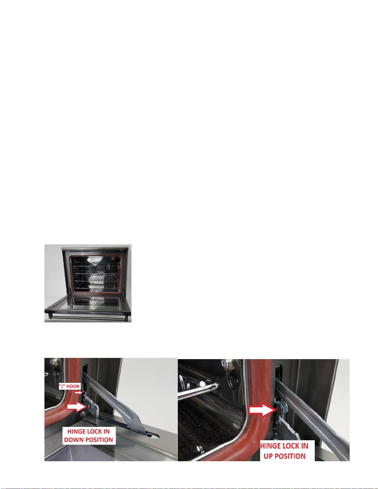
1. Open the door completely
2. Apply gentle downward pressure on the top of the door while moving each hinge lock to “UP” position, engaging
the “J” hook of the long arm (one lock per hinge)
Page 6
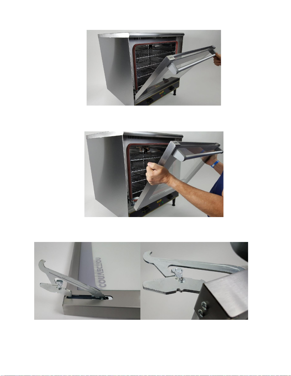
3. Tilt the door up at a 45-60-degree angle (hinge lever arm will be released)
4. Pull the door out of the hinge slot
*NOTE: What hinge looks like in the open position
Upon removal, the door can be washed or cleaned, both on the inside and on the outside.
Page 7
OVEN DOOR INSTALLATION
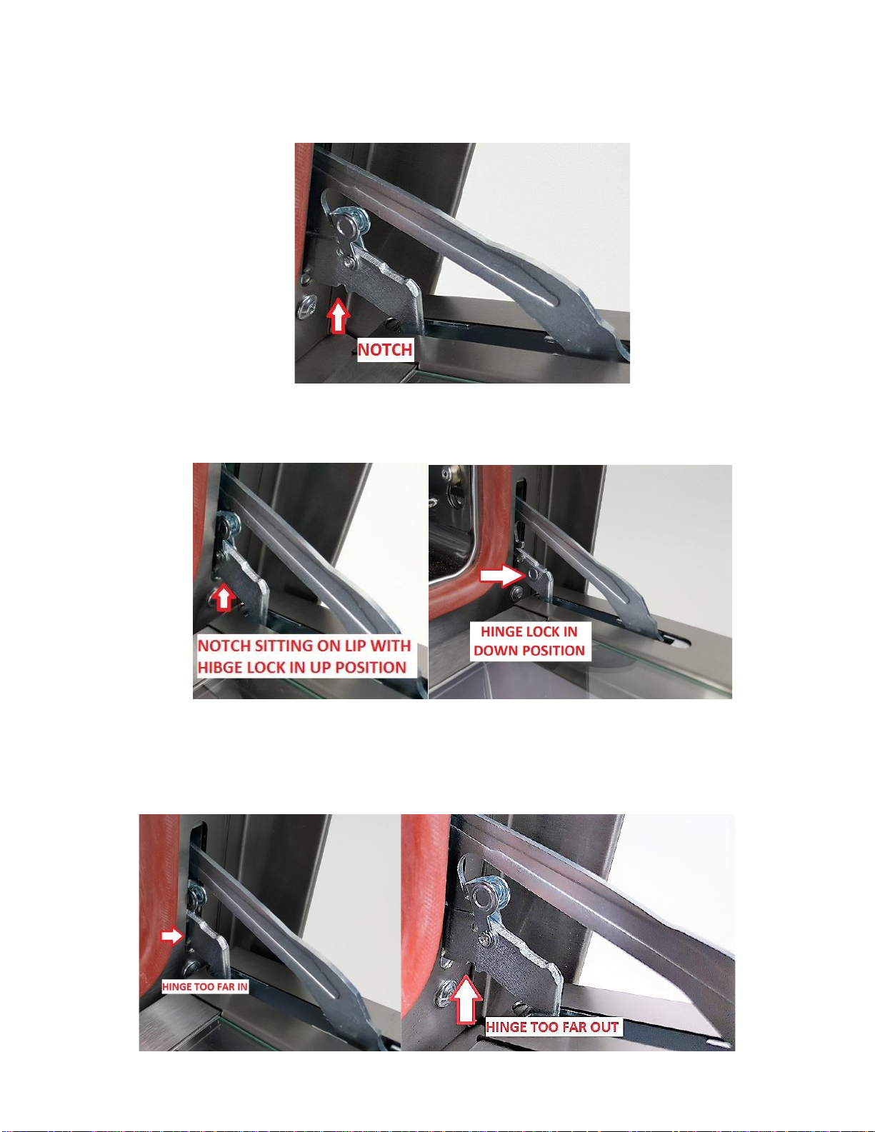
1. Ensure that the notch on the bottom of the hinge fits onto the lip in the opening of the oven frame
2. Move the hinge lock to the “down” position to restore proper hinge operation
3. Do NOT leave the Hinge lock in the “UP” position at the end of installation
NOTE: Incorrect hinge installation positions
Page 8
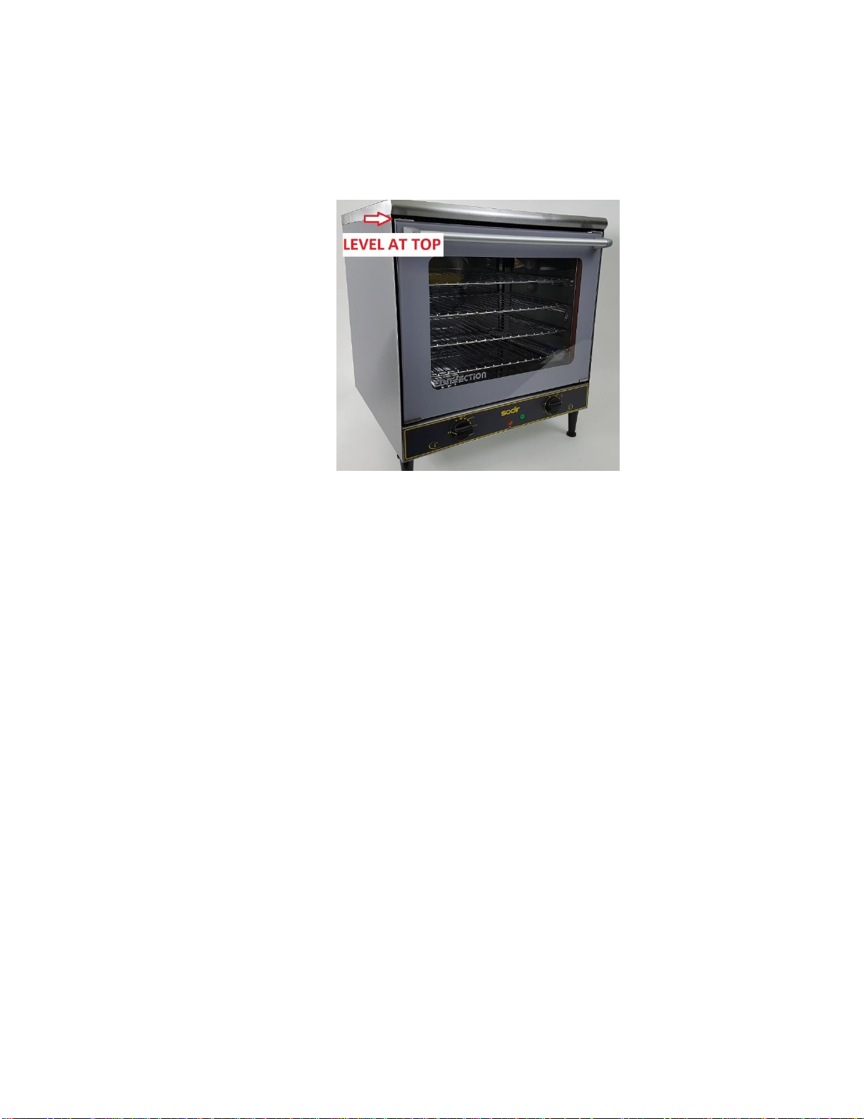
OVEN DOOR INSTALLATION COMPLETE
NOTE: Door should be level at the top edge to verify it has been installed properly
DO NOT spray the unit with any cleaning liquid before unplugging it
DO NOT allow water to drip into the housing or around the electrical components
DO NOT immerse in water for cleaning
DO NOT attempt to clean oven until cool
You should inspect all parts on a regular basis to ensure that all is in proper working order. If a part is damaged,
have the unit repaired by an authorized service agency prior to returning the unit to operation. If you have trouble
locating a service agency in your area, please consult our website at www.equipex.com or call us at 1-800-6497885 and ask for customer service.
Page 9
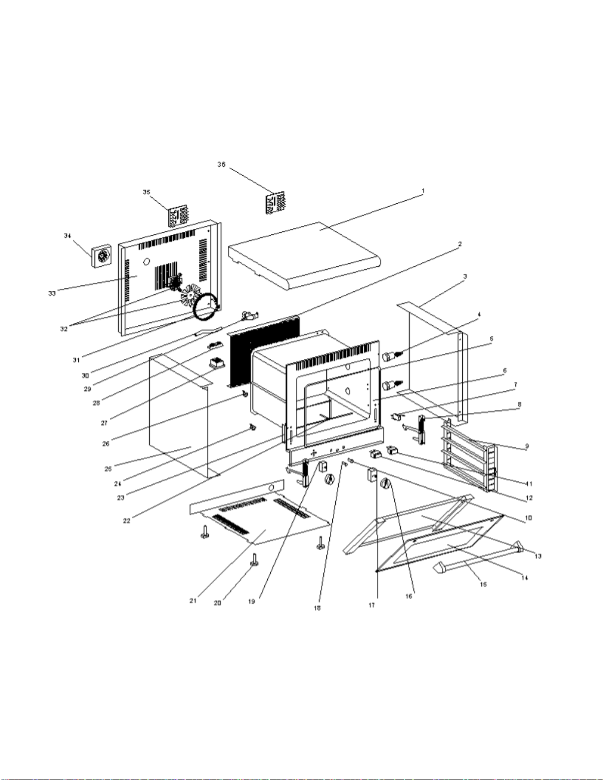
FC-100/103
Page 10
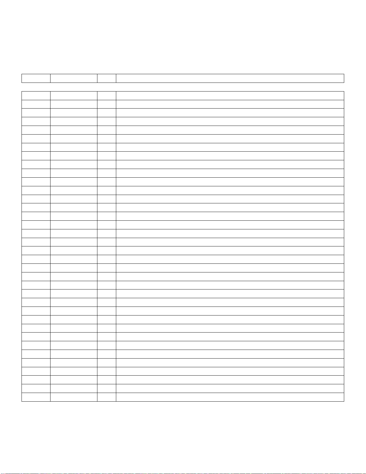
Parts List
Dwg #
Part #
Qty
Description
1
91049
1
Top Cover
2
91034
1
Ventilation Cover
3
91002D
1
Right Outside Cover
4
A18022
2
Light with Holder
5
H03006
1
Door Seal
6
91035SE
1
Oven Chamber
7
A07036
1
Door Switch
8
B09005
2
Door Hinge
9
91019ECHE
2
Shelf Holder
10
A08009
1
Green Power Light
11
A07015
1
Steam Momentary Switch
12
A07014
1
Motor Speed Switch
13
H01022
1
Inside Glass
14
H01021
1
Outside Glass
15
A15013
1
Handle
16
A14078
2
Knob
17
A02034
1
Timer
18
A08003
1
Orange Thermostat Light
19
A06042
1
Thermostat
20
A13006
4
Foot
21
91008
1
Bottom Cover
22
B04039/1
1
Steam Tube
23
B09007
2
Hinge Support
25
91002G
1
Left Side
26
A06048
1
Steam Thermostat
27
A05008
1
Contactor (Relay)
28
A16014
1
Six Position Domino (Terminal Block)
29
B10006
1
Electro gate (Water Valve)
30
H03020
1
Pipe
31
D02151
1
Convection Heating Element (Rear)
32
A03010
1
Motor
A03012
1
Motor Turbine (Fan)
33
91038
1
Back Cover
34
A03018
1
Cooling Fan
35
A03024
1
Electronic Control Board
36
A18023
1
Timer Tone Board
Page 11
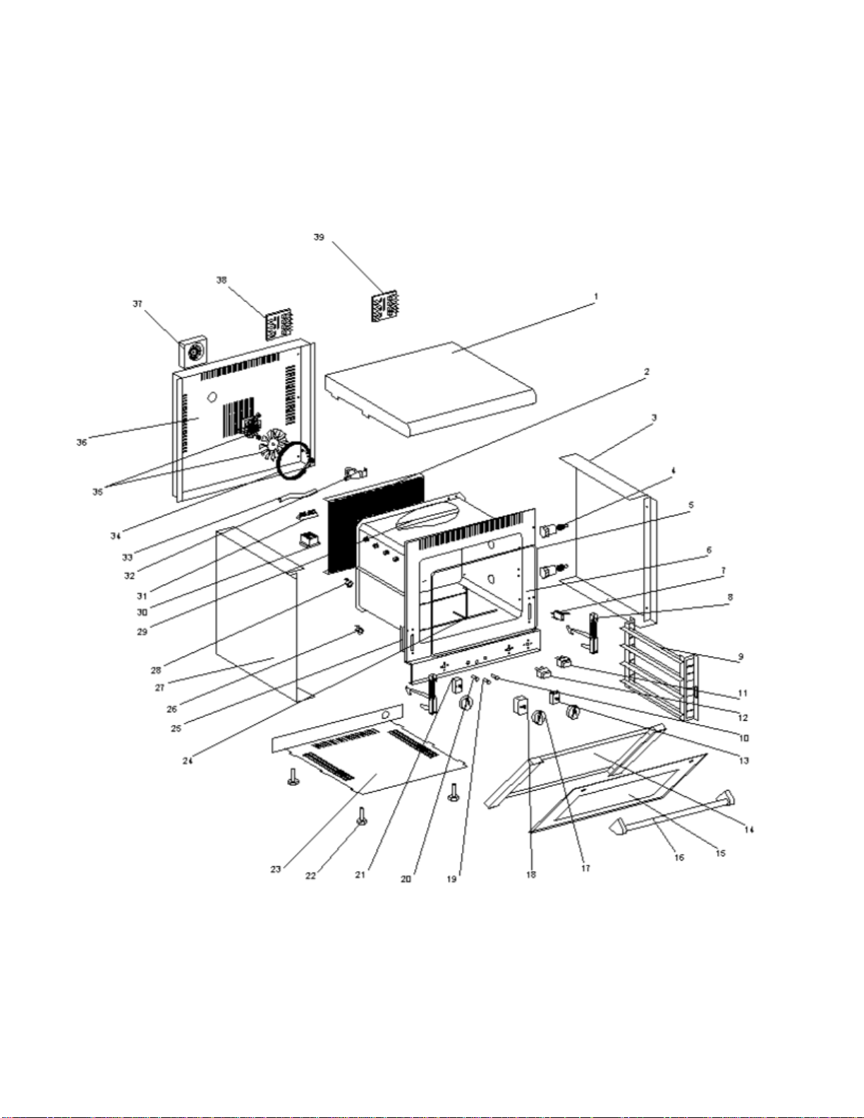
FC-100G/103G
Page 12
Parts List
Dwg #
Part #
Qty
Description
1
91049
1
Top Cover
2
91034
1
Ventilation Cover
3
91002D
1
Right Outside Cover
4
A18022
2
Light with Holder
5
H03006
1
Door Seal
6
91035SE
1
Oven Chamber
7
A07036
1
Door Switch
8
B09005
2
Door Hinge
9
91019ECHE
2
Shelf Holder
10
A08009
1
Green Power Light
11
A07015
1
Steam Momentary Switch
12
A07014
1
Motor Speed Switch
13
A01024
1
Commutator (Mode Switch)
14
H01022
1
Inside Glass
15
H01021
1
Outside Glass
16
A15013
1
Handle
17
A14078
3
Knob
18
A02034
1
Timer
19/20
A08003
2
Orange Thermostat Light
21
A06042
1
Thermostat
22
A13006
4
Foot
23
91008
1
Bottom Cover
25
B04039/1
1
Steam Tube
26
B09007
2
Hinge Support
27
91002G
1
Left Side
28
A06048
1
Steam Thermostat
29
D04025
4
Quartz Tube Heating Elements
30
A05008
2
Contactor (Relay)
31
A16014
1
Six Position Domino (Terminal Block)
32
B10006
1
Electro gate (Water Valve)
H03020
1
Pipe
33
D02151
1
Convection Heating Element (Rear)
34
A03010
1
Motor
35
A03012
1
Motor Turbine (Fan)
36
91038
1
Back Cover
37
A03018
1
Cooling Fan
38
A03024
1
Electronic Control Board
39
A18023
1
Timer Tone Board
Page 13

LIMITED WARRANTY
Your new EQUIPEX product is warranted to the original purchaser for a period of one year from the date of
purchase.
This limited warranty is against defects from original factory imperfections in material and/or workmanship and
includes labor for replacement of defective parts, provided repairs are performed by an authorized service agency. Our
obligation under this warranty is limited to repairing or replacing any part or parts thereof. The CUSTOMER must inform
the Service Agency of warranty coverage and provide a copy of the dated sales or delivery receipt BEFORE
WARRANTY REPAIRS BEGIN. Replacement parts and accessories are warranted for ninety (90) days from the date of
purchase when purchased separately and will be verified by dated sales receipt or packing slip for that item. All parts or
accessories replaced under warranty must be returned to the Service Agency.
This warranty applies only to equipment under normal use and service in the U.S.A. and Canada. It does not apply to
any item which has been repaired or altered in any way so as, in the judgment of EQUIPEX, to affect its reliability.
THE FOLLOWING ARE NOT COVERED UNDER WARRANTY:
1. Damage caused by abuse, misuse or dropping or other similar incidental damage caused by, or as a result of,
customer failure to follow assembly, operation, cleaning, user maintenance or storage instructions.
2. Labor to replace inoperative parts such as bulbs, plugs or racks due to normal wear and tear or abuse.
3. Materials or labor to repair scratched, stained, chipped, pitted, dented or discolored surfaces, attachments or
accessories.
4. Transportation charges to or from a service agency for repair of your machine. If you should have questions
relating to this issue, please call Equipex at 1-800-649-7885.
5. Labor charges to install or test attachments or accessories, which are replaced for any reason.
6. SHIPPING DAMAGES. Visible and hidden damages are the responsibility of the freight carrier. The
consignee must file the claim promptly against the carrier. KEEP ALL ORIGINAL CONTAINERS AND
PACKAGING MATERIAL FOR CARRIER INSPECTION.
7. Products placed or stored in the equipment are not subject to this warranty and no responsibility is assumed
thereof.
THIS WARRANTY IS GIVEN EXPRESSLY AND IN LIEU OF ALL OTHER WARRANTIES, EXPRESSED OR IMPLIED, FOR
MERCHANTABILITY AND FOR FITNESS TOWARD A PARTICULAR PURPOSE AND CONSTITUTES THE ONLY WARRANTY
MADE BY EQUIPEX, LLC. IT NEITHER ASSUMES, NOR AUTHORIZES ANY PERSON TO ASSUME FOR US, ANY OTHER
LIABILITY IN CONNECTION WITH THE SALE OF THE SUBJECT EQUIPMENT.
For service, please call EQUIPEX at 1-800-649-7885, menu option #3
100 Niantic Avenue – Suite 104 Providence, Rhode Island 02907 U.S.A.
Tel: (401) 273-3300 Fax: (401) 273-3328
Website: www.equipex.com e-mail: [email protected]
 Loading...