

Page 1
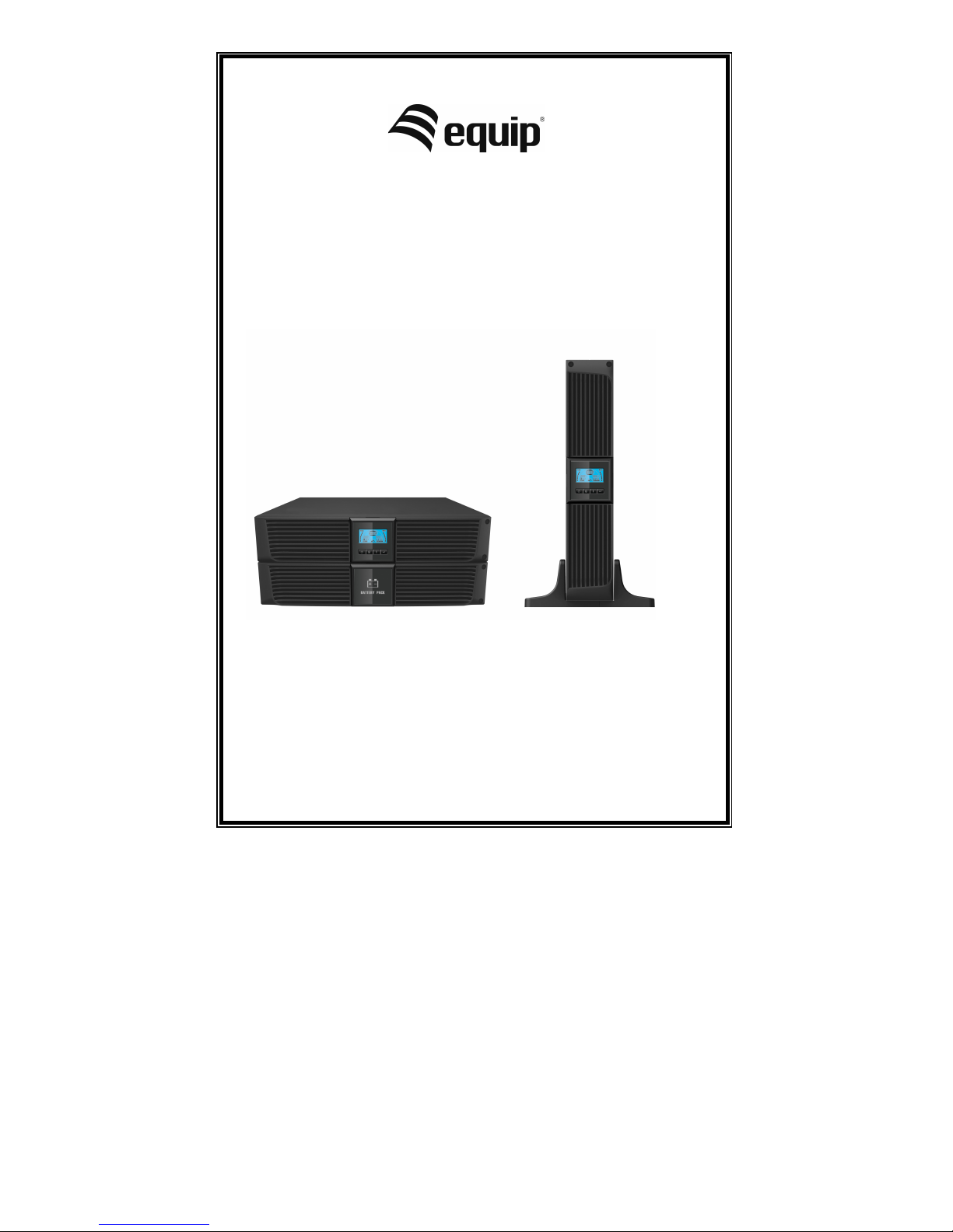
USER MANUAL
Line Interactive UPS
1000VA/1500VA/2000VA/3000VA
Uninterruptible Power Supply System
Copyright © Digital Data Communications GmbH, Germany. All Rights Reserved.
Page 2

IMPORTANT SAFETY
INSTRUCTIONS
SAVE THESE INSTRUCTIONS
This manual contains important instructions for
1000VA/1500VA/2000VA/3000VA series that should be
followed during installation and maintenance of the UPS
and batteries. Please read all safety and operating
instructions before operating the UPS. Adhere to all
warnings on the unit and in this manual. And follow all
operating and user instructions.
Page 3

CONTENTS
1. Introduction ············································································· 1
2. Safety Warning ········································································· 2
2.1 Description of Commonly Used Symbols ···································· 3
3. Installation ··············································································· 4
3.1 Inspection of Unit ·································································· 4
3.2 Unpacking the Cabinet ··························································· 4
3.3 UPS Setup ··········································································· 4
3.4 EBM Installation (Optional) ······················································ 8
3.5 UPS Initial Startup ······························································· 14
4. Operation ··············································································· 15
4.1 Display Panel ····································································· 15
4.2 Operating Mode ·································································· 19
4.3 Configuring Load Segment ···················································· 19
4.4 Configuring UPS for EBM Numbers ········································ 20
4.5 Configuring Green Function ··················································· 21
5. Communication Port ······························································· 22
5.1 RS-232 and USB Communication Ports ··································· 22
5.2 Emergency Power Off (EPO) ················································· 22
5.3 Network Management Card (Optional) ····································· 23
6. UPS Maintenance ···································································· 24
6.1 UPS and Battery Care ·························································· 24
6.2 Storing the UPS and Batteries ··············································· 24
6.3 Time to Replace Batteries ····················································· 24
6.4 Replacing UPS Internal Batteries ············································ 25
6.5 Testing New Batteries ·························································· 27
6.6 Recycling the Used Battery: ·················································· 27
7. Specification ·········································································· 28
7.1 Specification ······································································· 28
7.2 Rear Panels ······································································· 30
8. Trouble Shooting ···································································· 33
8.1 Audible Alarm Trouble Shooting ············································· 33
8.2 General Trouble Shooting ····················································· 33
9. Software Installation ······························································· 34
Page 4

1
1. Introduction
This line-interactive series is compact and pure sine wave UPS and it is
designed for essential applications and environment, such as desktops,
servers, workstations, and other networking equipments. These models are
available in the output ratings of 1000VA, 1500VA, 2000VA and 3000VA.
The series protects your sensitive electronic equipments against power
problems including power sags, spike, brownouts, line noise and blackouts.
The series is convertible to rack and tower forms. It can be placed either in
Rack 2U or Tower form. The front panel of the UPS includes LCD display
and four control buttons that allow users to monitor, configure and control
the units. On LCD, it also includes a LCD graphical bar, two status
indications and four alarm indications. A control button from the front panel
allows users to silence off the AC fail alarm and initiate the UPS self test
sequence as well. The UPS case for 1000VA ~ 3000VA is made of metal.
This series is powered from the AC mains and supply AC outputs via
receptacles on the rear panel. Communication and control of UPS is
available through serial or USB ports located on the rear panel. The serial
port will support communications directly with a server.
Features:
! Microprocessor control guarantees high reliability
! High frequency design
! Built-in boost and buck AVR
! Easy battery replacement design
! Selectable input and output range
! Cold start capability
! Built-in Dry contact/RS-232/USB communication port
! SNMP allows for web-based remote or monitoring management
! Enable to extend runtime with scalable external battery
module(EBM)
! Overload, short-circuit, and overheat protection
! Rack/Tower 2 in 1 Design
! 19 inches rack mount available for all models
Page 5

2
2. Safety Warning
DANGER:
This UPS contains high voltages. All repairs and service should be
performed by authorized service personnel only. There are no user
serviceable parts inside the UPS.
WARNING:
! This UPS contains its own energy source (batteries).The UPS output
may carry live voltage even when the UPS is not connected to an AC
supply.
! To reduce the risk of fire or electric shock, install this UPS in a
temperature and humidity controlled, indoor environment, free of
conductive contaminants.(Ambient :0-40°C)
! To reduce the risk of fire, connect to a circuit breaker provided with 20
amperes maximum branch circuit over-current protection.
! To comply with international standards and wiring regulations,
the sum of the leakage currents of the UPS and the connected loads
must not exceed 3.5mA.
! The socket outlet that supplies the UPS shall be installed near the
UPS and shall be easily accessible.
! Protective earthling connections shall be such that disconnection of a
protective earth should be made at one point that is the furthest away
from the UPS, maintaining the dedicated line in order to secure
equipotential connection.
! The UPS and EBMs connected in series should be installed closely
such that the operators can not touch the interconnecting wire which
is basic insulated from primary circuit.
CAUTION:
! Batteries can present a risk of electrical shock or burnt from high
short-circuit current. Observe proper precautions. Servicing should be
performed by qualified service personnel knowledgeable of batteries
Page 6
3
and required precautions. Keep unauthorized personnel away from
batteries.
! Proper disposal of batteries is required. Refer to your local codes for
disposal requirements.
! Never dispose of batteries in a fire. Batteries may explode when
exposed to flame.
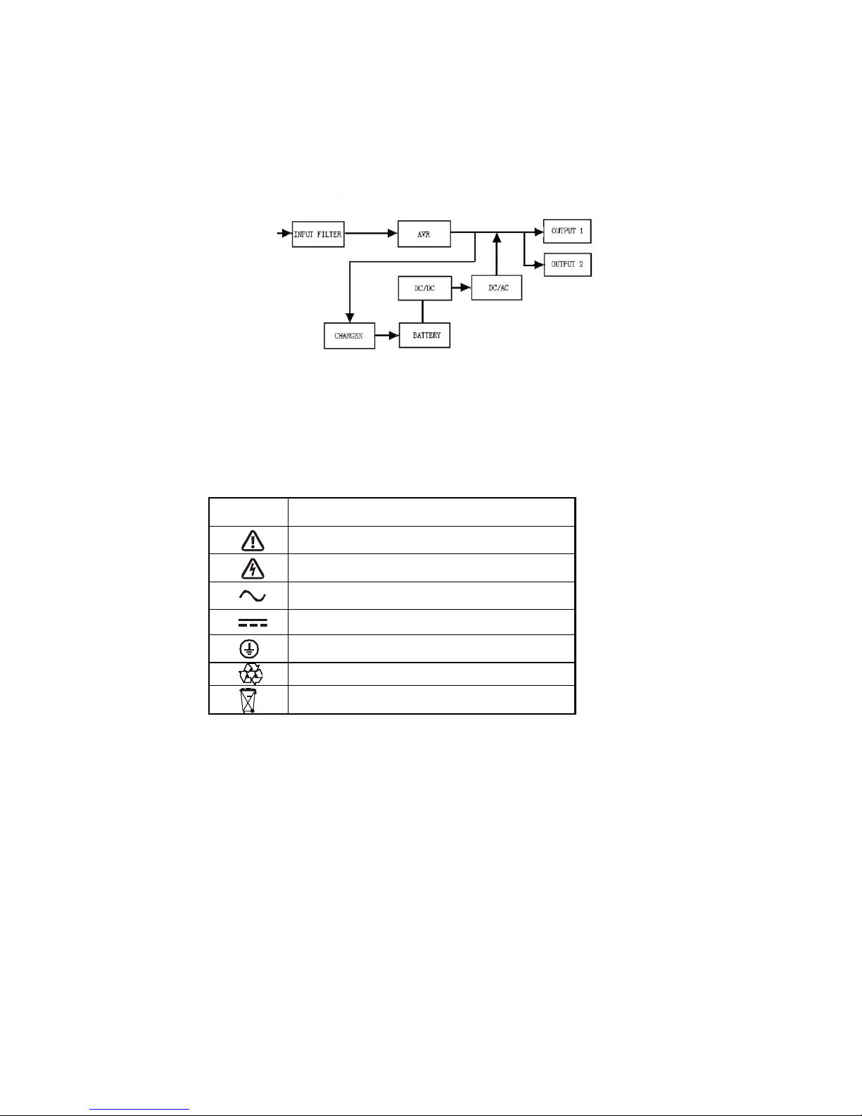
Following figure shows the basic internal circuit configuration of the UPS
2.1 Description of Commonly Used Symbols
Some or all of the following Notations may be used in this manual and may
appear in your application process. Therefore, all users should be familiar with
them and understand their explanations.
Table1. Description of Commonly Used Symbols
Symbol
Description
Alert you to pay special attention
Caution of high voltage
Alternating current source (AC)
Direct current source(DC)
Protective ground
Recycle
Keep UPS in a clear area
Page 7

4
3. Installation
3.1 Inspection of Unit
Inspect the UPS upon receiving. If the UPS is apparently damaged during
the shipment, please keep the box and packing material in original form for
the carrier and notify the carrier and dealer immediately.
3.2 Unpacking the Cabinet
To unpack the system:
1. Open the outer carton and remove the accessories packaged with the
cabinet.
2. Carefully lift the cabinet out of the outer carton and set it on a flat, stable
surface.
3. Discard or recycle the packaging in a responsible manner, or store it for
future use.
3.3 UPS Setup
All model series are designed for tower and rack purpose. They can be
installed into a 19 inches equipment rack. Please follow the instruction for
Tower Setup and Rack-Mount Setup.
" Tower setup
This series of UPS can be placed horizontally and vertically. As a tower
configuration, it is provided with the optional UPS stands to stabilize the
UPS when the UPS is positioned in vertical. The UPS stand must be
attached to the bottom of the tower.
Page 8
5
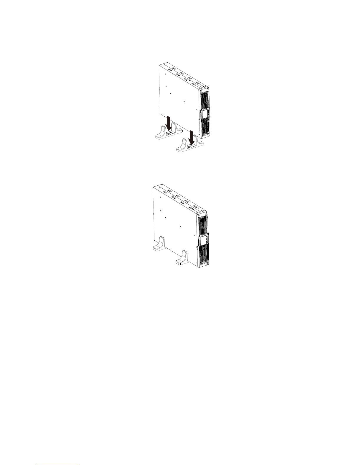
Use the following procedure to install UPS in UPS stands.
1. Slide down the UPS vertically and put two UPS stands at the end of the
tower.
2. Place down the UPS into two stands carefully.
Page 9
6
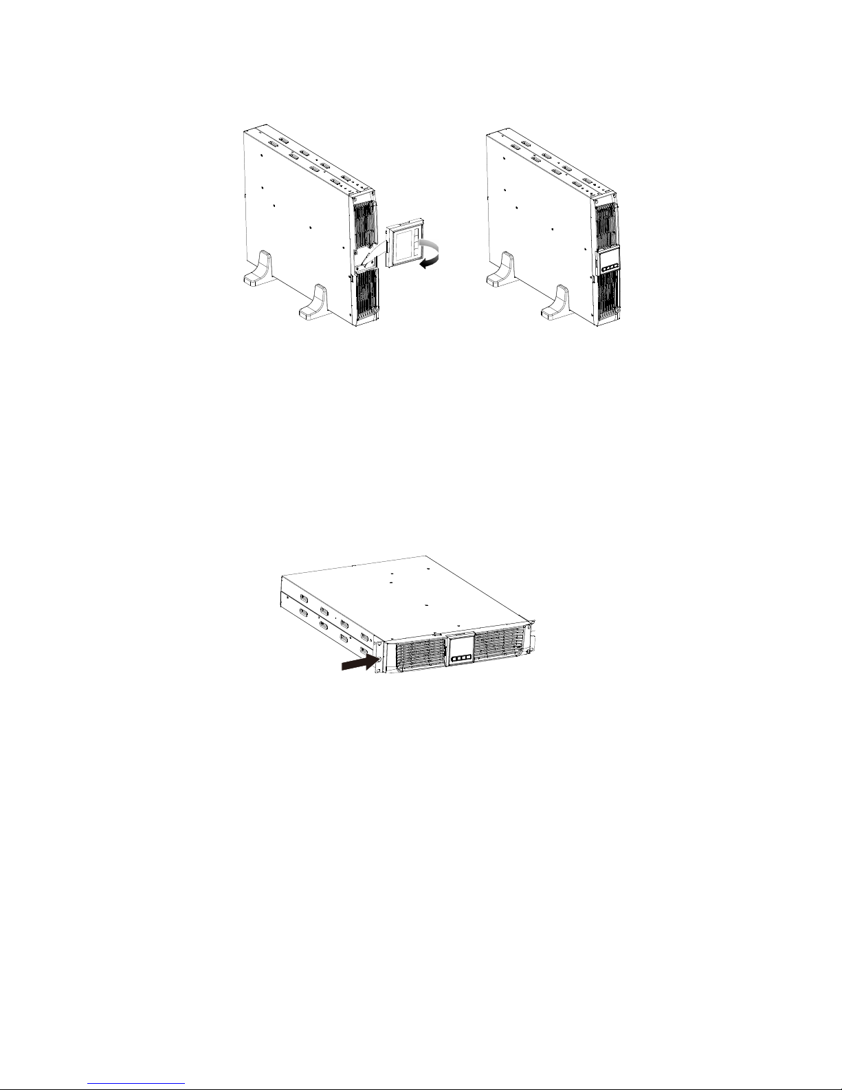
3. Pull out the LCD box and rotate it in a clockwise direction to 90 degree
and then push it back in the front panel.
" Rack-mount setup
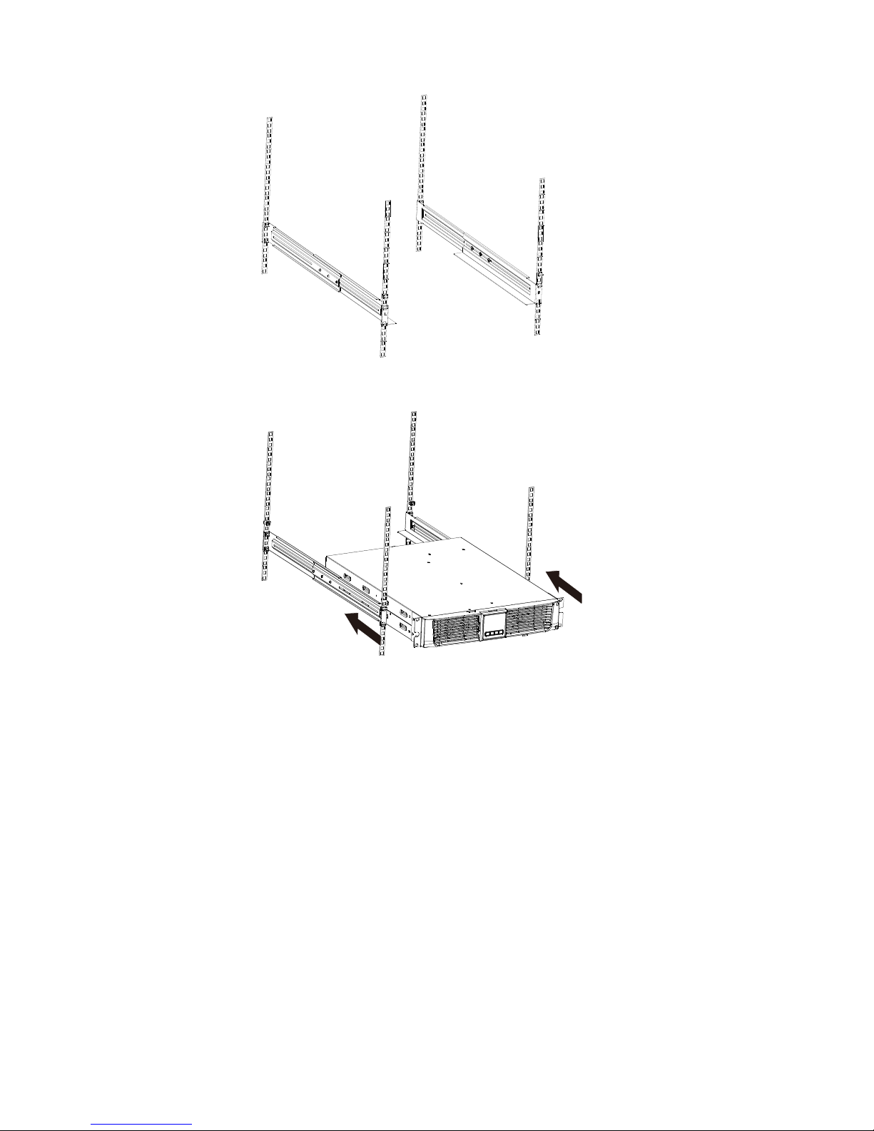
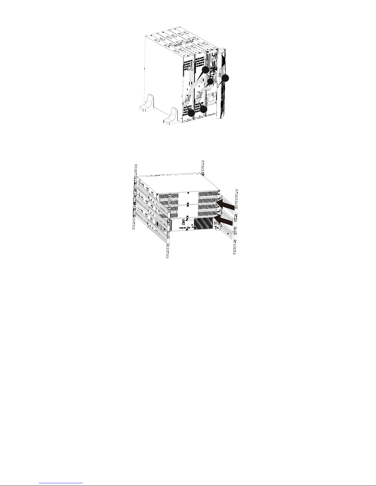
The series can be installed in 19 inches racks. Both the UPS and external
battery enclosure need 2U of valuable rack space.
Use the following procedure to install UPS in a rack.
1. Align the mounting ears with screw holes on the side of the UPS, and
tighten the screw.
Page 10
7
2. Assemble the rack rails with the rack-mounting.
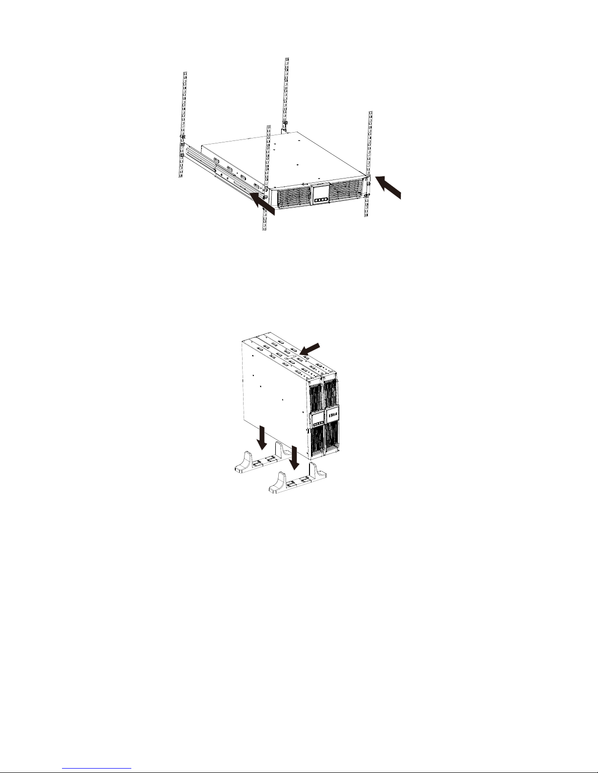
3. Slide in the UPS into the rack rail and lock it in the rack enclosure.
Page 11
8
4. Tighten the screw, and the load can then be connected
3.4 EBM Installation (Optional)
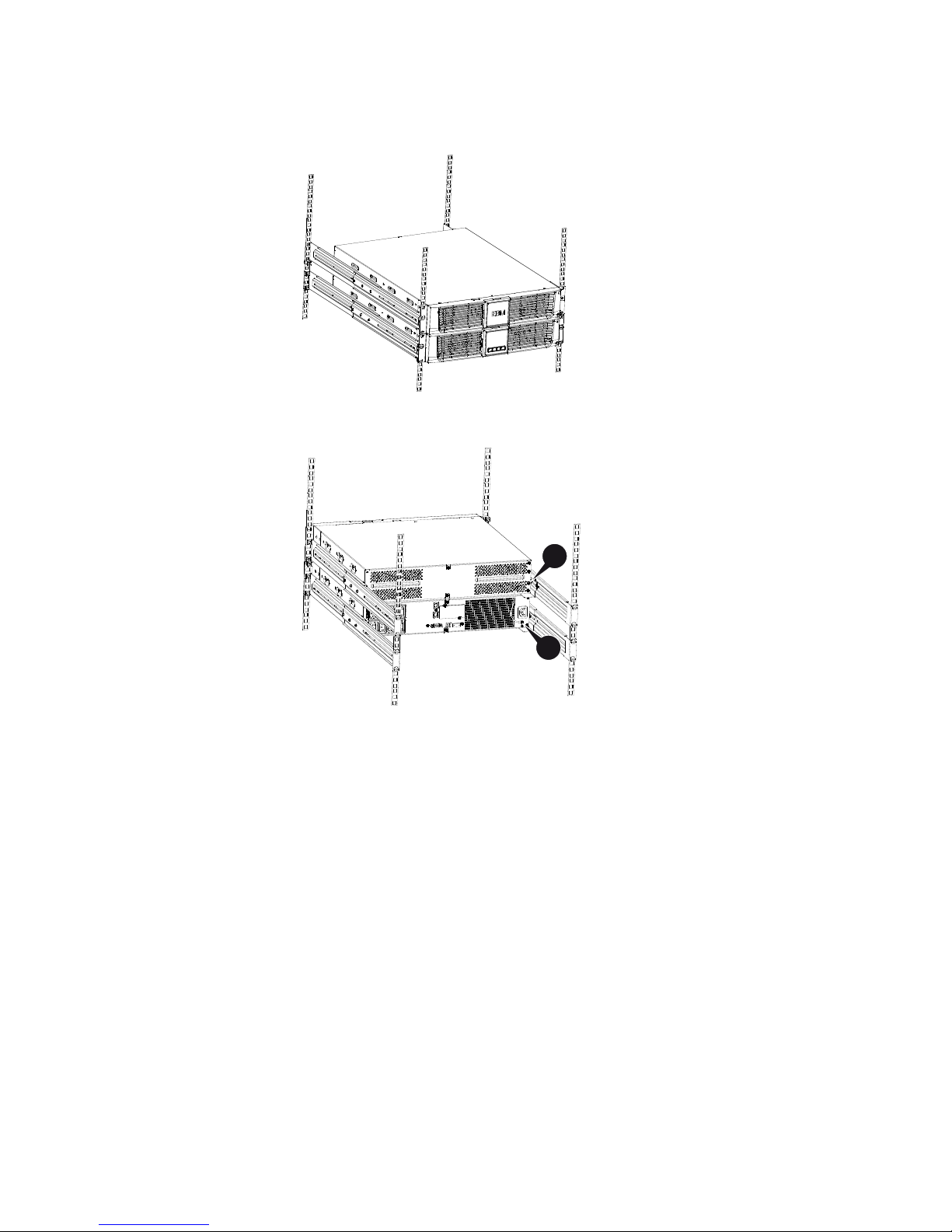
" Connecting the EBM in Tower form:
1. Slide down the UPS and EBM vertically and place two UPS stands with
the extend part at the end of the tower.
2. Tighten the screw on the metal sheet for stabilization
Page 12

9
3. Connect the Earth line from UPS (port A ) to EBM (port B)
4. Take off the front panel, and connect the battery terminal (A) from UPS
to EBM terminal (B) shown as below. Users need to remove the small
gate(C) on side of the front panel to allow the outlet wire of the EBM to
pass through the gate and then reassemble front panel.
B
A
C
B
A
Page 13
10
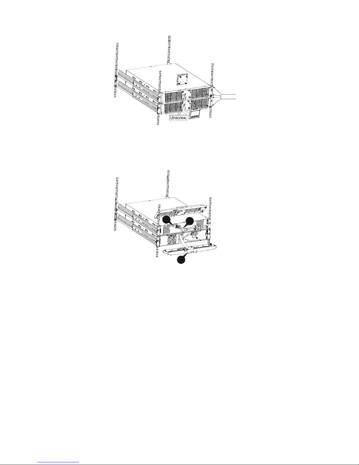
" Connecting the EBM in a rack form
1. Using the same method as assembling UPS in a rack form, assemble
EBM into the rack-mounting on the top or bottom of the UPS.
2. Connect the earth line from UPS (port A ) to EBM (port B )
A
B
Page 14
11
3. Take off the LCD box, and unscrew the internal screws.
4. Take off the front panel, and connect the battery terminal (A) from UPS
to EBM terminal (B) shown as below. Users need to remove the small
gate(C) on side of the front panel to allow the outlet wire of the EBM to
pass through the gate and then reassemble front panel.
5. After installing the UPS into rack, the load can then be connected to
UPS. Please make sure the load equipment is turned off before plugging
all loads into the output receptacle.
Unscrew
B
A
C
Page 15
12
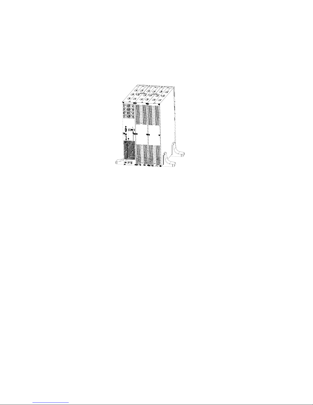
" Connecting the Multiple EBMs
1000VA/1500VA/2000VA and 3000VA UPS include external battery port
that allows users to connect multiple EBM in order to provide additional
backup time. Follow the procedure to install multiple EBM as below.
Connecting multiple EBMs in Tower form
1. Connect Earth line between UPS and the first EBM, and then connect Earth
Line between the first EBM and the second EBM.
2. Take off the front panel, and connect the battery terminal (A) from UPS to
EBM terminal (B) shown as below. And then connect the battery terminal
(D) from the first EBM to the battery terminal (E) from the second EBM.
Users need to remove the small gate(C) on side of the front panel to
allow the outlet wire of the EBM to pass through the gate and then
reassemble front panel.
Page 16
13
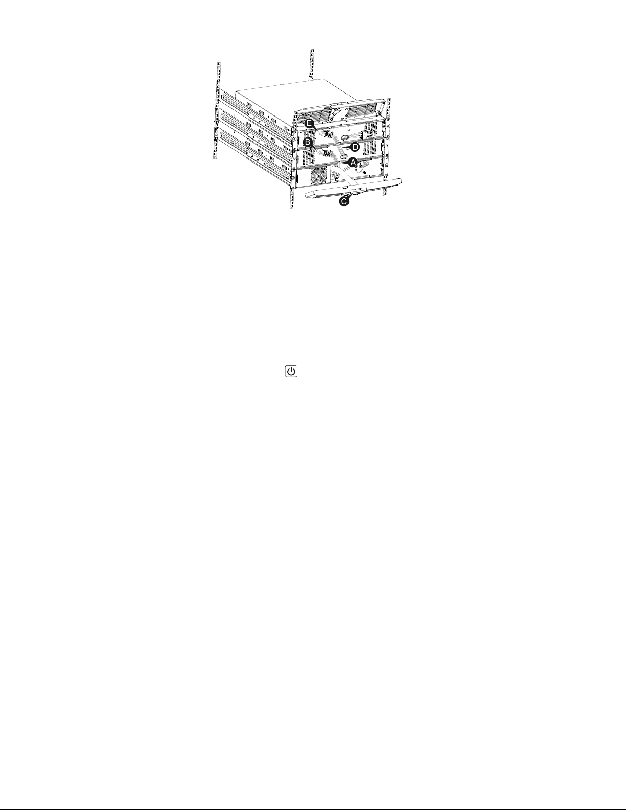
Connecting the Multiple EBMs in rack form
1. Connect Earth line between UPS and the first EBM, and then connect
Earth Line between the first EBM and the second EBM.
2. Take off the front panel, and connect the battery terminal (A) from UPS
to EBM terminal (B) shown as below. And then connect the battery
terminal (D) from the first EBM to the battery terminal (E) from the
second EBM. Users need to remove the small gate(C) on side of the
front panel to allow the outlet wire of the EBM to pass through the gate
and then reassemble front panel.
B
C
A
D
E
Page 17
14
Note: Three or more EBMs can be connected to the UPS in the same way
as shown above.
3.5 UPS Initial Startup
To start up the UPS:
1. Verify that the internal batteries are connected. If optional EBMs are
installed, verify that the EBMs are connected to the UPS.
2. Plug the equipment to be protected onto the UPS, but do not turn on the
protected equipment.
3. Plug in the UPS input power cord. The UPS front panel display
illuminates and UPS status display shows “STbY”
4. Press and hold the button more than 3 seconds. The UPS status
display changes to “NORM”
6. Check the UPS display for active alarms or notices. Resolve any active
alarms before continuing. See “Troubleshooting”
8. If optional EBMs are installed, see “Configuring UPS for EBM numbers”
on page 21 to set the number of installed EBMs.
9. To change any other factory-set defaults, see “Operation”
Note: At initial startup, the UPS sets system frequency according to input
line frequency.
Page 18
15
4. Operation
4.1 Display Panel
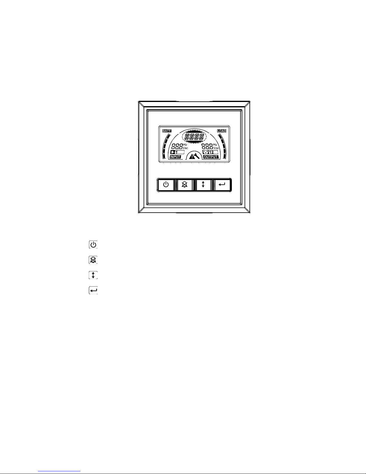
The UPS has a four-button graphical LCD with dual color backlight.
Standard back-light is used to light up the display with black text and a blue
background. When the UPS has a critical alarm, the backlight changes the
background to red. See Figure below:
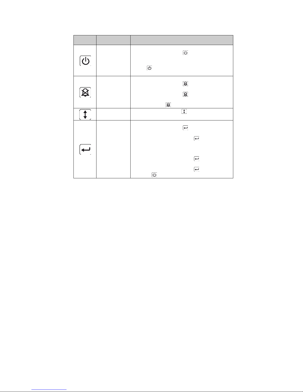
" Control Buttons functions:
There are four buttons on the control panel.
ON/OFF
UPS Test /Alarm Silence
Select
Enter
Page 19
16
The following table describes the functions of the LCD control buttons.
Table2. Description of control button
Control
Button
Switch
Function
ON/OFF
--To turn on/off the UPS
Press and hold the button more than 3 seconds.
--To release the UPS from faulty mode
Cut off input power and then press and hold the
button more than 2 seconds to shut down the
UPS.
UPS Test
Alarm Silence
--To perform basic function test
Press and hold the button for 3 seconds.
--To perform Battery life test
Press and hold the button for 10 seconds.
-- To disable alarm buzzer
Press the button for one second.
Select
Press the Select button to select the settings
value one by one
Enter
-- Enter settings mode
Press and hold the button more than 3 seconds.
-- Enter settings item
Press and hold the Enter button more than one
second, the UPS allows users to configure the
settings, and the settings string will flash.
-- Confirm settings
Press and hold the Enter button for one second.
-- Exit Settings mode
Press and hold the Enter button for 3 seconds
or button for 0.5 second.
Note: Ensure the battery is fully charged during line mode when
conducting functional tests.
Note: A list of events shown as below is not able to disable alarm buzzer:
Low Battery, Fan Failed, Fan Fault Time Out, and Overheat.
Note: User can disable the alarm buzzer when it’s sounding, but an alarm
will still sound when a new alarm event is encountered.
Page 20
17
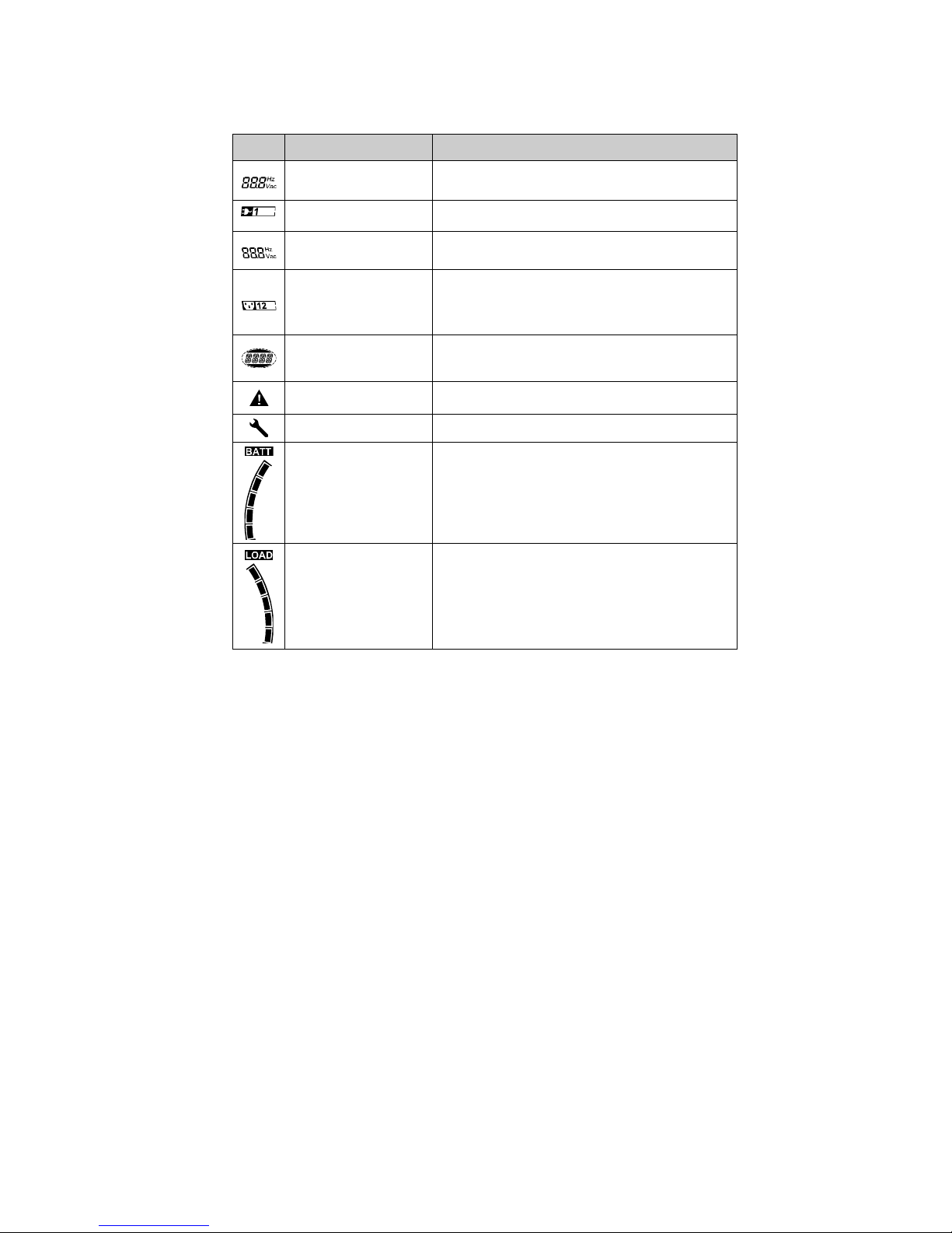
" LCD display functions:
The following table describes the functions of the LCD display.
Table3. Description of LCD display function
No.
Description
Function
Input frequency and
voltage
Indicate the value of input frequency and voltage
Input plug indicator
Light on when the input power is at no loss.
Output frequency and
voltage
Indicate the value of output frequency and
voltage
Output plug indicator
The UPS has two groups of outlets. The
output plug indicator will light on if there is
output power respectively.
UPS status/user
setting display String
Strings Indicate the UPS status( see Table 4)
Strings Indicate user setting options( see Table
5)
Warning indication
Light on when the UPS is failure or alarm.
Settings
Light on when the UPS under settings mode.
Battery volume level
display
Indicate the amount of battery volume
remaining. Each battery volume level bar
indicates a 20% of total battery volume
Load capacity level
display
Indicate the percentage of UPS load capacity
which is being used by the protected
equipment. Each LCD level bar indicates a
20% of the total UPS output capacity.
Page 21

18
" UPS Status Display String Description:
The following table shows the description of the LCD display string:
Table4. UPS Status Display String
LCD Display String
Description
STbY
UPS work at Standby mode
IPVL
Input voltage is too low
IPVH
Input voltage is too high
IPFL
Input frequency is too low
IPFH
Input frequency is too high
NORM
UPS work at Line mode
AVR
UPS work at AVR mode
bATT
UPS work at Battery mode
TEST
UPS work at battery life/function test mode
OPVH
Battery mode, the output is too high
OPVL
The output is too low
OPST
Output short
OVLD
Overload
bATH
Battery voltage is too high
bATL
Battery voltage is too low
OVTP
Internal temperature is too high
FNLK
Fan is locked
bTWK
Batteries are weak
" User Setting String Description:
The following table shows the options that can be changed by user.
Table5. User Setting String
OPV
Output voltage mode select
[220]= 220V
[230]= 230V
[240]= 240V
AVR
Input type select
[000]= Normal range mode
[001]= Wide range mode
[002]= Generator mode
EbM
External battery module
(EBM)
0~9 is the number of external battery
module
TEST
Auto self-test
[000]=Disable
[001]=Enable
AR
Automatic restart
[000]=Disable
[001]=Enable
Page 22

19
GF
Green function
[000]=Disable
[001]=Enable
bZ
Buzzer control
[000]=Disable
[001]=Enable
LS1
Load segment 1
[000]=Turn off [001]=Turn
on
LS2
Load segment 2
[000]=Turn off [001]=Turn
on
4.2 Operating Mode
" Normal range mode: Under Input mode the UPS accepts AC input
voltage range for +/-20%.
" Generator mode: Under generator mode, the low frequency transfer
point can go as low as 40Hz and as high as 80Hz before being
transferred to battery mode.
" Wide range mode: Under Input settings mode, the UPS accepts AC input
voltage range for -30% ~ +20%.
" Battery mode
When the UPS is operating during a power outage, the alarm beeps once
every four seconds and the LCD display string shows “bATT” to indicate the
UPS work at battery mode.
If battery volume becomes low while in Battery mode, the alarm beeps once
every second and the LCD display string shows “bATL”.
" Standby mode
When the UPS is turned off and remains plugged into a power outlet, the
UPS is on Standby mode. The LCD display string shows “STbY” to indicate
that power is not available to your equipment. The battery recharges when
necessary.
4.3 Configuring Load Segment
Load segment are sets of receptacles that can be controlled through the
display. Each UPS has two configurable load segments. See “Rear Panels”
on page 30 for load segment for each UPS model.
Page 23

20
Note: This configuring can be operated when UPS is power on.
1K model has only one load segment, cannot configure.
To configure the load segment through the display:
1. Enter settings mode: Press and hold the Enter button more than 3
seconds. Then UPS will transfer to setting mode.
2. Select settings items: Press the Select button to select the setting
items show as Table 5.
3. Enter settings item: When the LCD display “LS1” or “LS2”, press the
enter button more than one second to enter the setting item and the
settings string will flash.
4. Select setting value: Press the Select button to select the settings
value. Select the value [001] or [000] to set the desired load segment
ON or OFF.
5. Confirm settings: Press and hold the Enter button for one second,
ups will return to current setting item.
6. Exit Settings mode: Press and hold the Enter button for 3 seconds
or button for 0.5 second to exit setting mode.
4.4 Configuring UPS for EBM Numbers
To ensure the LCD displays the correct battery volume, configure the UPS
for the correct number of EBMs:
Note: 1K model has no EBM, cannot configure
1. Enter settings mode: Press more than 3 seconds to enter setting
mode.
2. Select settings items: Press to select setting items as “EbM”.
3. Enter settings item: Press more than one second to enter the
setting item.
4. Select setting value: Press the Select button to select the number
of EBM according to your UPS configuration.
5. Confirm settings: Press and hold the Enter button one second, ups
will return to current setting item.
Page 24

21
6. Exit Settings mode: Press and hold the Enter button for 3 seconds
or button for 0.5 second to exit setting mode.
4.5 Configuring Green Function
Green Function is that when an insignificant amount of load is detected,
the UPS will shut down output automatically on battery mode.
The green function is disabled on default mode and user can configure
Green Function through the display:
1. Enter settings mode: Press more than 3 seconds to enter setting
mode.
2. Select settings items: Press to select setting items as “GF”.
3. Enter settings item: Press more than one second to enter the
setting item.
4. Select setting value: Press the Select button to select “001”.
5. Confirm settings: Press and hold the Enter button for one second,
ups will return to current setting item.
6. Exit Settings mode: Press and hold the Enter button for 3 seconds
or button for 0.5 second to exit setting mode.
Page 25
22
5. Communication Port
5.1 RS-232 and USB Communication Ports
To establish communication between the UPS and a computer, connect
your computer to one of the UPS communication ports using an
appropriate communication cable.
When the communication cable is installed, power management software
can exchange data with the UPS. The software polls the UPS for detailed
information on the status of the power environment. If a power emergency
occurs, the software initiates the saving of all data and an orderly shutdown
of the equipment.
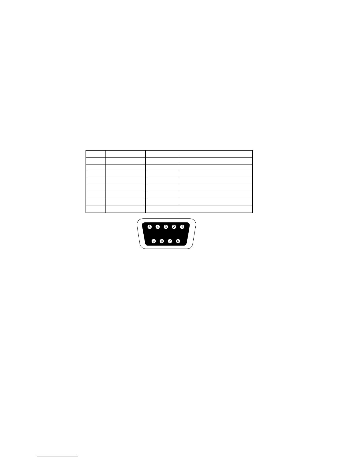
The cable pins for the RS-232 communication port are identified as below,
and the pin functions are described in Table 6.
Table6. DB9 Female (RS232 +dry contact)
PIN #
Description
I/O
Function Explanation
1
BATLOW
Output
Battery low
2
RXD
input
RXD 3 TXD
Output
TXD 4 DTR
Input
N/A 5 Common
--
Common (tied to chassis)
6
DTR
Input
N/A 7 RING
Output
Ring 8 LNFAIL1
Output
Line fail
RS232 Communication Port The connector shall be a DB-9 Female connector. ( a filtered connector may be required to meet EMI requirements)
5.2 Emergency Power Off (EPO)
EPO is used to shut down the load from a distance. This feature can be
used for shutting down the load on Emergency.
Page 26
23
Warning:
This circuit must be separated from hazardous voltage circuits by
reinforced insulation.
Caution:
The EPO must not be connected to any utility connected circuits.
Reinforced insulation to the utility is required. The EPO Switch must have
a minimum rating of 24Vdc and 20mA and be a dedicated latching-type
switch not tied into any other circuit. The EPO signal must remain active
for at least 20ms for proper operation
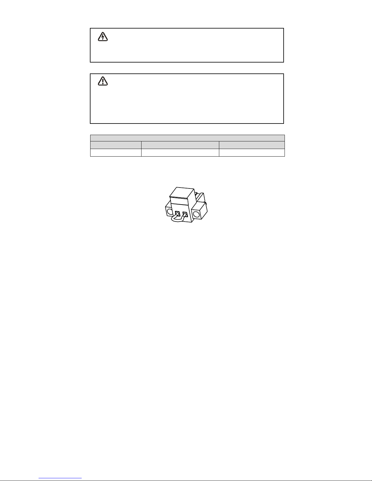
EPO Connections
Wire Function
Terminal Wire Size Rating
Suggested Wire Size
EPO
4-0.32mm2(12-22AWG)
0.82mm2(18AWG)
Note: Leave the EPO connector installed in the EPO port on the UPS even if
the EPO function is not need.
EPO Connector
5.3 Network Management Card (Optional)
Network Management Card allows the UPS to communicate in a variety of
networking environments and with different types of devices. The series
UPS has one available communication slot for Webpower or other optional
card to achieve remote management of the UPS through internet/ intranet.
Please contact your local dealer for further information.
Page 27

24
6. UPS Maintenance
6.1 UPS and Battery Care
For the best preventive maintenance, keep the area around the UPS clean
and dust-free. If the atmosphere is very dusty, clean the outside of the
system with a vacuum cleaner. For long battery life, keep the UPS at an
ambient temperature of 25°C (77°F)
6.2 Storing the UPS and Batteries
When the UPS is intended to store for a long period, recharge the battery
every 6 months by connecting the UPS to utility power. The batteries
charge to 90% capacity in approximately 4 hours. However, it is
recommended that the batteries charge for 48 hours after long-term
storage.
6.3 Time to Replace Batteries
When LCD backlight turns to red, the screen displays “bTWK” and there is
a continuous sounding, the battery may need to be replaced. Please check
the battery connection or contact your local dealer to order new battery.
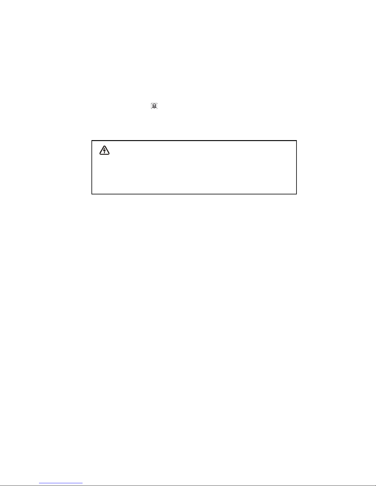
WARNING:
Turn off the UPS and disconnect the utility power cord from the wall outlet.
Servicing should be performed by qualified service personnel
knowledgeable of batteries and required precautions. Keep unauthorized
personnel away from batteries
Batteries can present a risk of electrical shock or burn from high short
circuit current. The following precautions should be observed:
1. Remove watches, rings, or other metal objects.
2. Use tools with insulated handles.
3. Do not lay tools or metal parts on top of batteries.
4. Wear rubber gloves and boots.
5. Disconnect the charging source prior to connecting or disconnecting
battery terminal.
When replacing batteries, replace with the same type and number of
batteries or battery packs. Contact your service representative to order new
batteries.
Page 28
25
Do not dispose of battery in a fire. Batteries may explode when exposed to
flame.
Proper disposal of batteries is required. Refer to your local codes for
disposal requirements.
Do not open or mutilate the battery. Released toxic electrolyte is harmful to
skin and eyes.
Note: If you are not qualified service personnel to replace the battery, do
not attempt to open the battery cabin. Please call local dealer or distributor
immediately.
6.4 Replacing UPS Internal Batteries
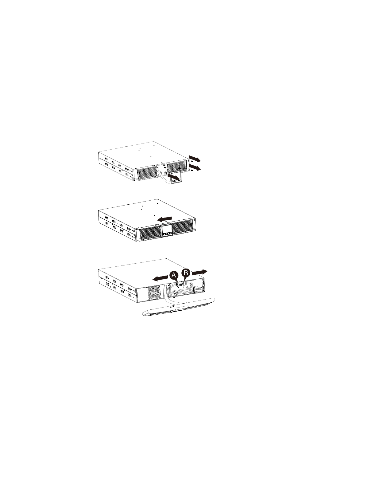
Follow the steps and Charts as below to replace batteries:
1. Take off the LCD box, and remove the screws.
2. Slide and Pull the front panel leftward and then take it off.
3. Disconnect the cable from the UPS and battery pack.
Page 29
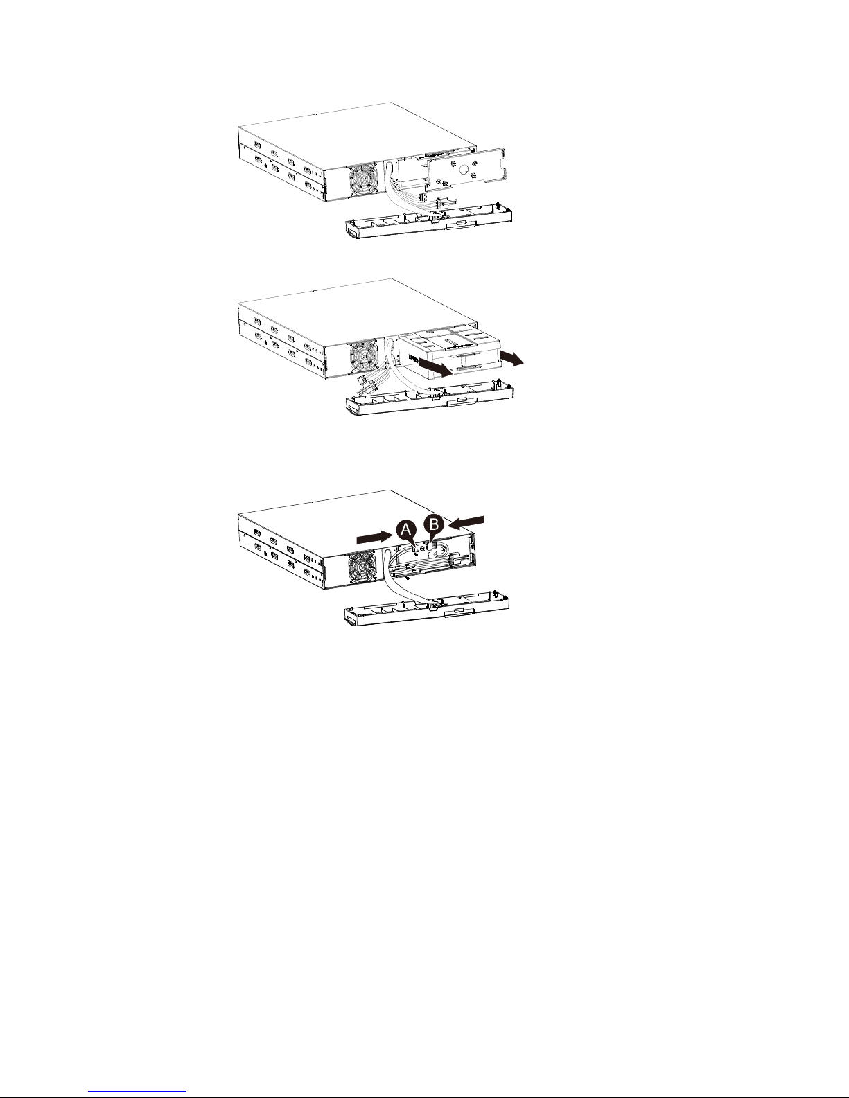
26
4. Remove the right inner battery bracket.
5. Pull the battery pack out onto flat area.
6. Install new battery pack into UPS.
7. Screw up the battery bracket and reconnect the battery cable A and B
8. Re-install the front panel back to UPS.
Page 30
27
6.5 Testing New Batteries
For a battery test, please check:
" The batteries must be fully charged.
" The UPS must be in Normal mode with no active alarms.
" Don’t take on/off the load.
To test batteries:
1. Connect the UPS to utility power for at least 48 hours to charge the
batteries.
2. Press and hold the button 10 seconds to start the battery test. The
status display string shows “TEST”
6.6 Recycling the Used Battery:
Warning:
" Never dispose the batteries in a fire. It may explode.
" Do not open or mutilate the batteries. Released electrolyte is harmful
to the skins and eyes. It may be toxic. A battery can present a risk of
electrical shock and high short circuit current.
To recycle properly the used battery, please do not discard the UPS,
battery pack and batteries into the trash bin. Please follow your local laws
and regulations; you may contact your local recycling waste management
center for further information to dispose properly of the used UPS, battery
pack, and batteries.
Page 31

28
7. Specification
7.1 Specification
Table7. Electrical Specification
Model
1000
1500
2000
2000S
3000
3000S
Capacity
Watt
900W
1350W
1800W
2700W
Input
Input voltage range
0-300VAC
Frequency range
50/60Hz ±5Hz for Normal Mode
40-80Hz for Generator Mode
Output
Voltage
220/230/240VAC
Voltage Regulation
(Batt. Mode)
±5%
Frequency
50Hz or 60Hz
Waveform
Pure sinewave
Overload rating
Line Mode
≥110% ±10%,Fault after 3 Minutes.
≥150% ±10%,Fault after 200ms
Battery Mode
≥ 110 % ±10%,Fault after 30 Seconds
≥ 120 % ±10 %, Fault after 100ms
Internal battery
(Standard model)
Battery Type
2*12V/9AH
3*12V/9AH
4*12V/9AH
6*12V/9AH
Backup Time
(at full load)
3′
3′
3′
3′
Recharge Time
8 hours to
90% after
discharged
4 hours to
90% after
discharged
4 hours to
90% after
discharged
4 hours to
90% after
discharged
External battery
module(EBM)
Battery Type
N/A
12V/7AH
Interface
RS-232
Yes
USB
Yes
Dry-Contact
N/A
Optional
SNMP
N/A
Optional
EPO
N/A
Optional
Page 32
29
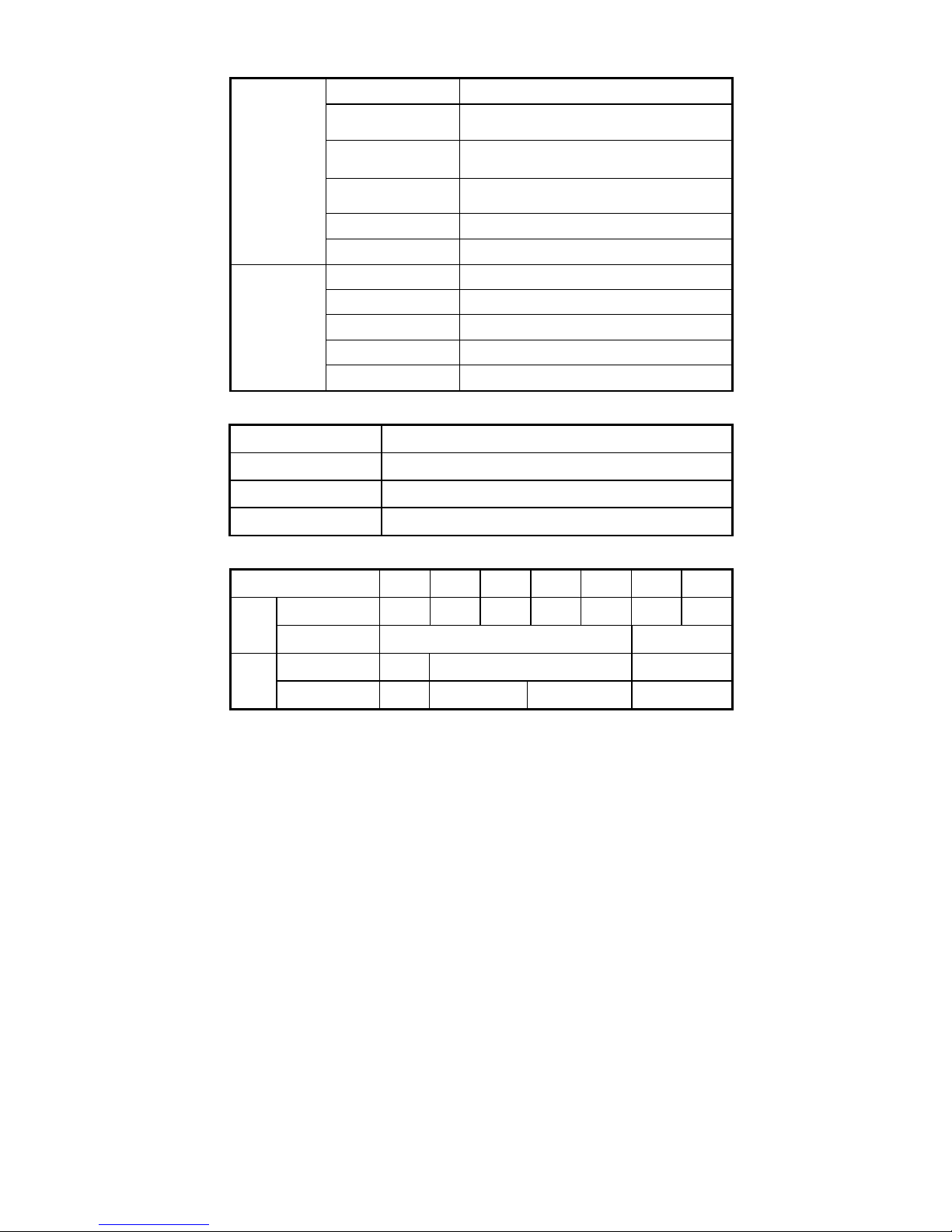
Table8. Indicators and Audible alarm
Indicator
AC Mode
NORM---normal mode
Backup Mode
Show “bATT” and sounding every 4 seconds
Load/Battery Level
LCD showing
UPS Fault
LCD show red screen and “ **** ”
Overload
LCD show red screen and “ OVLD ”
Low Battery
LCD show red screen and “ bATL ”
Audible alarm
Backup Mode
Sounding every 4seconds
Low Battery
Sounding every second
UPS Fault
Continuously Sounding
Overload
Sounding every second
Battery Replacement
Sounding every second
Table9. Operating Environment
Temperature
0 to 40°C
Humidity
20%-80% relative humidity (non-condensing)
Altitude
<1500m
Storage Temperature
-15° to 45° C
Table10. Dimensions and weights
Model
1000
1500
1500S
2000
2000S
3000
3000S
UPS
Case
Net weight (kg)
13.0
17.8
10.0
21.0
10.7
30.4
15.7
Dimension (mm)
(W x H x D)
438X86.5x436
438X86.5x608
EBM
Case
Dimension (mm)
(W x H x D)
N/A
438X86.5x436
438X86.5x608
Net weight (kg)
N/A
20.5
27.5
33.3
Page 33
30
7.2 Rear Panels
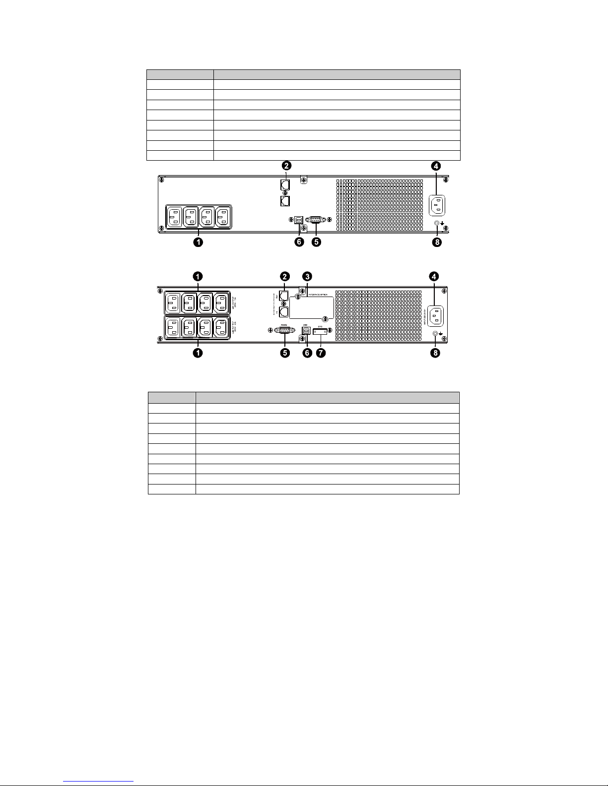
The UPS rear panel description table and pictures are shown as below:
LS1 OUT PUT
250V~ 10 A
IN O UT
NETW ORK /TEL EPH ONE PR OTEC TION
RS232
USB
INPUT 2 20-240V ~
1000VA Standard model rear panel
1500VA Standard /Super charger model rear panel
No.
Function(1000VA&1500VA)
1
AC Output
2
Modem/Network Surge Protection
3
SNMP Port
4
AC Input
5
RS232 / Dry-Contact Communication Port
6
USB Port
7
EPO
8
Earth Line Port
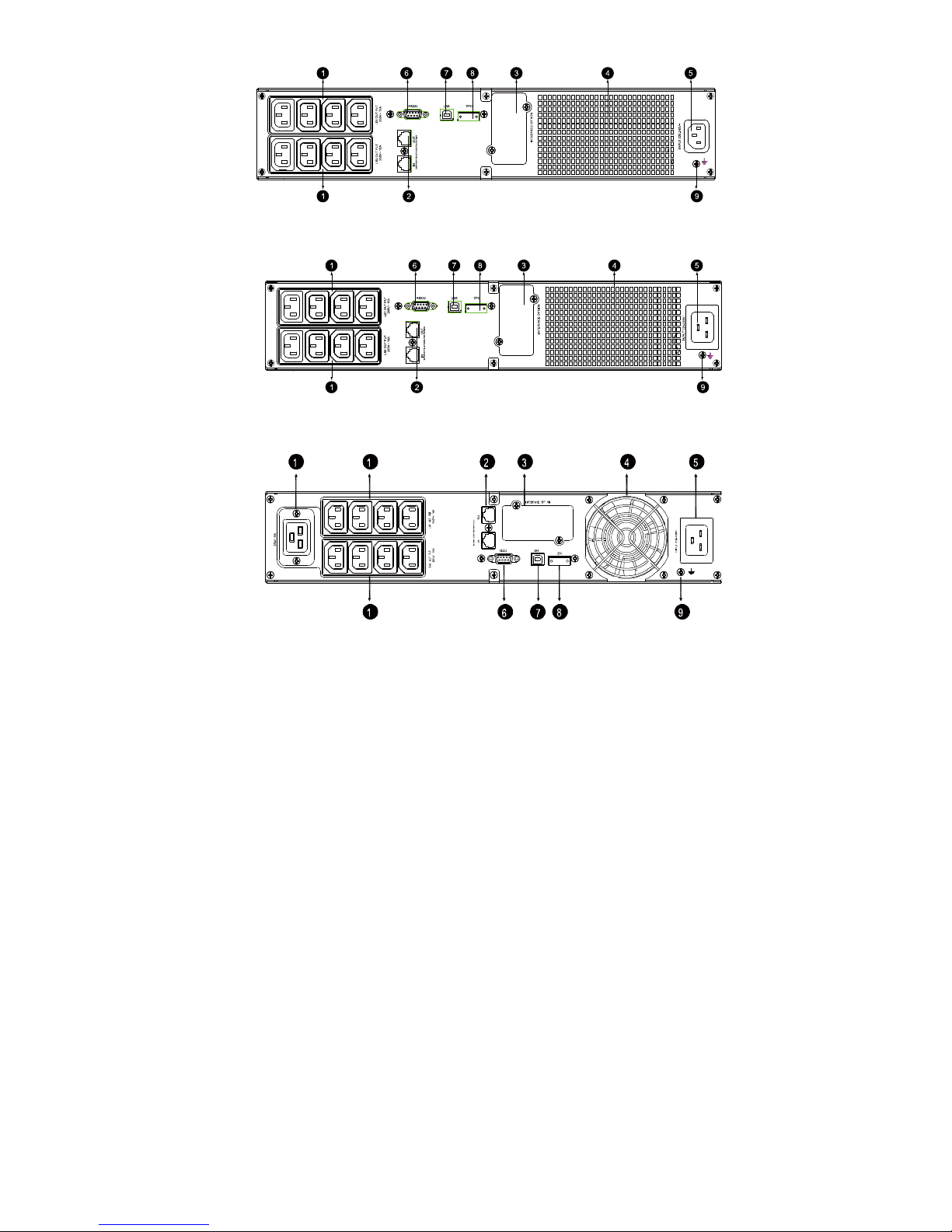
No.
Function(2K/3KVA Standard & Supper charger model)
1
AC Output
2
Modem/Network Surge Protection
3
SNMP Port
4
Fan
5
AC Input
6
RS232 / Dry-Contact Communication Port
7
USB Port
8
EPO
9
Earth Line Port
Page 34
31
2000VA Standard model rear panel
2000VA Super charger model rear panel
3000VA Standard & Supper charger model rear panel
Page 35
32
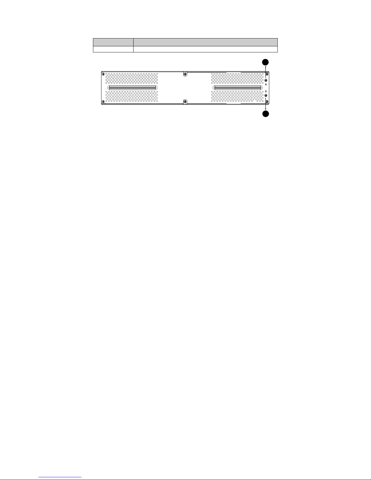
The EBM rear panel description table and picture are shown as below:
1
1
36V, 48V &72V EBM rear panel
No.
Function(36V, 48V &72V EBM)
1
Earth Line Port
Page 36

33
8. Trouble Shooting
8.1 Audible Alarm Trouble Shooting
Indication
Cause
Solution
Sounding every 4
seconds
The UPS is on battery
mode
Check the input voltage
Sounding every Second
and “bATL” on screen
The battery voltage is
low
Save your work and turn off your
equipment
Sounding every second
and “OVLD” on screen
Output overload
Check load level indicator and
remove some load
Continuously sounding
and red display
The UPS fails
Please contact your local dealer
8.2 General Trouble Shooting
Problem
Cause
Solution
The UPS can't be
turned on when power
switch is pressed
Internal fuse may be
broken
Please contact your local dealer
UPS is on and no
power to load
Output Jumpers is not
connected correctly
Check output Jumpers
No power on output
receptacle
Check if the LS1 and LS2 are set
up from "001 to 000".
Backup time is short
Battery is empty
Re-charge the battery at least 24
hours
Battery aging
Replace Battery
Continuously sounding
and display turn to
red
The UPS fails
Please contact your local dealer
Buttons does not work
The setting mode is not
a right path
please see right configuring
method
Button is Broken
Please contact your local dealer
Page 37
34
9. Software Installation
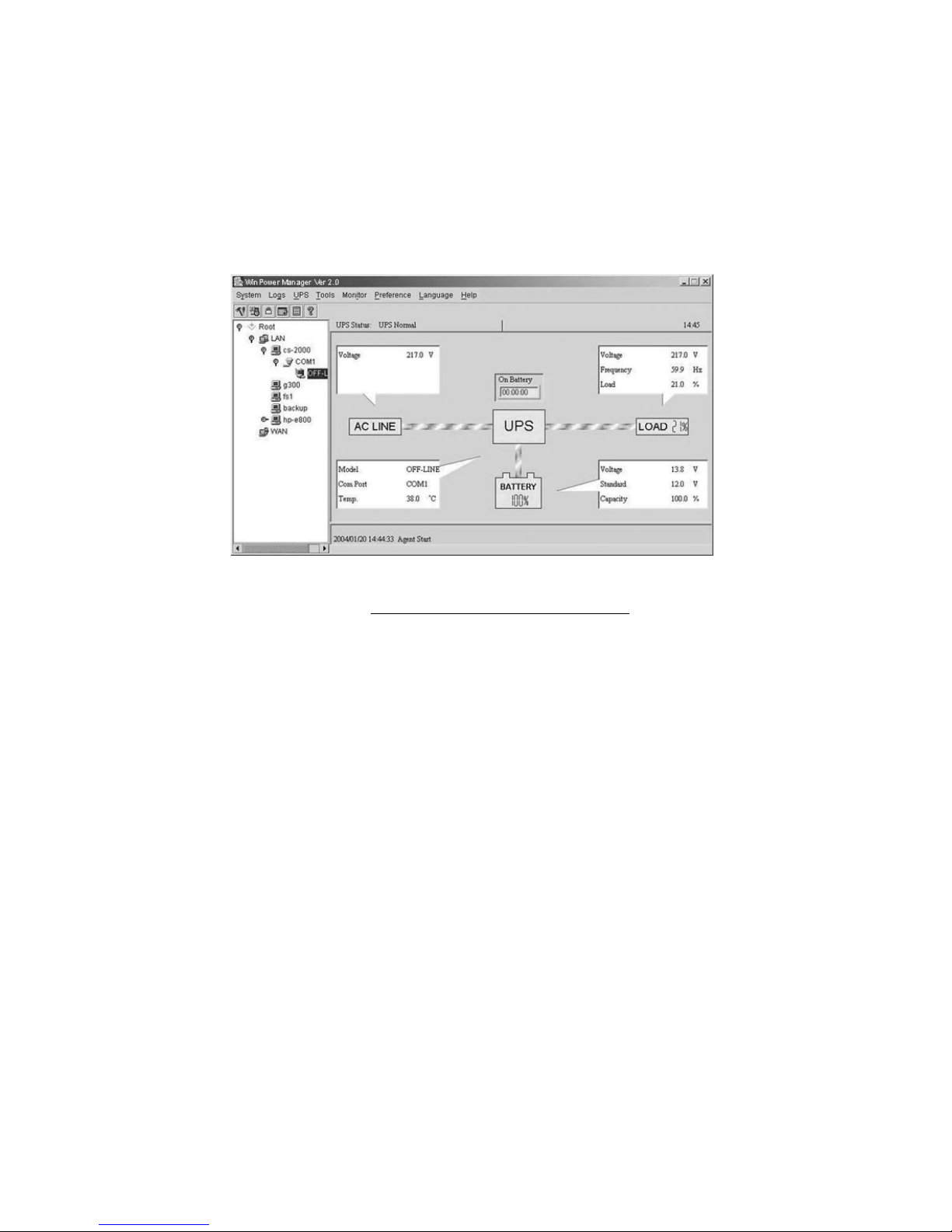
Winpower is UPS monitoring software, featuring user-friendly interface to
monitor and control your UPS. This unique software provides complete
power protection for computer system while power failure. With the
software users can monitor any UPS status on the same LAN. Furthermore,
a UPS can provide security protection for more than one computer on the
same LAN at the same time, such as shutting down system in security,
saving application data and shutting down the UPS when power fails.
Installation procedure:
1. Go to the website: http://www.ups-software-download.com/
2. Choose the operation system you need and follow the instruction
described on the website to download the software.
3. When downloading all required files from the internet, enter the serial No:
511C1-01220-0100-478DF2A to install the software.
When your computer restarts, the Winpower software will appear as a
green plug icon located in the system tray, near the clock.
Page 38

35
614-00766-01
 Loading...