

Page 1
Manual
www.equip-info.net
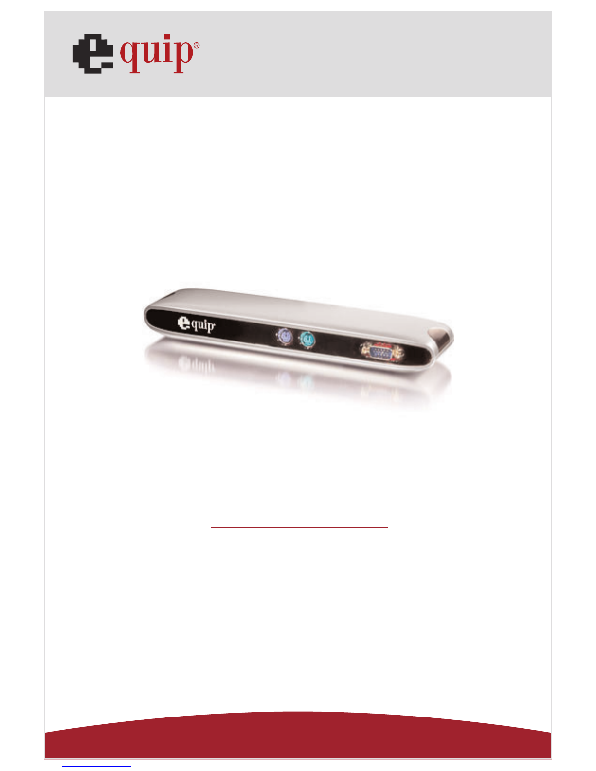
USB 2.0 VGA LAN DOCK
english
Page 2

Manual_Page 2
www.equip-info.net
Contents
1.0 INTRODUCTION
________________________________________________________________________________
3
2.0 FEATURES AND SPECIFICATIONS
____________________________________________________
3
3.0 SYSTEM REQUIREMENTS
_____________________________________________________
___________
3
4.0 PACKAGE CONTENTS
____________________________________________________________________
4
5.0 CONNECTORS
________________________________________________________________________________
4
6.0 AVAILABLE FUNCTIONS
____________________________________________________________________
5
7.0 LED INDICATOR
________________________________________________________________________________
5
8.0 INSTALLING USB 2.0 VGA LAN DOCK
____________________________________________
6
9.0 DRIVER INSTALLATION
_____________
_______________________________________________________
6
9.1 Win98/98SE Driver Installation
____________________________________________________________
6
9.2 WinME Driver Installation
________________________________________________________________
15
9.3 Win2000 Driver Installation
____________________________________________________________
18
9.4 WinXP Driver Installation
________________________________________________________________
21
9.5 WinVista Driver Installation
____________________________________________________________
23
10.0 THINGS YOU NEED TO KNOW
________________________________________________________
27
11.0 SET UP THE PRINTER DEVICE
________________________________________________________
29
11.1 For Windows 98/SE/ME
________________________________________________________________
29
11.2 For Windows 2000/XP/Vista
____________________________________________________________
31
12.0 SET UP THE HYPERTERMINAL WITH USB TO SERIAL PORT
________
32
13.0 UNINSTALLING USB 2.0 VGA LAN DOCK
________________________________________
33
13.1 REMOVE THE DEVICE
____________________________________________________________________
33
14.0 UNINSTALL THE DRIVER
________________________________________________________________
33
14.1 For Windows 98/SE/ME
________________________________________________________________
34
14.2 For Windows 2000/XP
____________________________________________________________________
35
14.3 For Windows Vista
________________________________________________________________________
35
15.0 TROUBLE SHOOTING
____________________________________________________________________
37
16.0 APPLICATION NOTE
________________________________________________________________________
38
Page 3

Manual_Page 3
www.equip-info.net
1. Instruction
Thank you for ordering the USB 2.0 VGA LAN DOCK. The USB 2.0 VGA LAN DOCK is an
intelligent expansion module, which connects to a PC or notebook via Universal Serial Bus
(USB) port and VGA output port, providing one high-speed RS-232 serial port, one printer
port, one PS/2 keyboard & mouse, 3 downstream USB 2.0 ports and one Ethernet access
and one extending VGA display output port. The USB 2.0 VGA LAN DOCK features easy
connectivity for traditional serial devices, keyboard, mouse and other USB devices and
provides up to 480Mbps USB 2.0 High Speed capability. Also add one extra USB Ethernet
adapter and extra VGA display to your PC or notebook in seconds.
2.0 Features and Specifications
• One high-speed serial port, one printer port, one PS/2 keyboard & mouse, three USB
2.0 High Speed downstream ports, one USB Ethernet adapter and one VGA port to your
PC or notebook.
• Improve the inconvenience of configuring old PC solutions like card extension solutions,
which require adjusting IRQ or jumper settings and the incompatibility of various
brands of docking solutions or bus repeaters.
• Avoid the hassle of removing your PC case, or rebooting the operating system during
installation.
• Built-in 10/100Mbps Fast-Ethernet and IEEE802.3x flow control function for 100BASETX and 10BASE-T.
• Complies with USB specifications 2.0 (and under), with IEEE802.3u 100BASE-TX and
with IEEE802.3 10BASE-T standards.
• Complies an extra VGA output, can easily connect a larger monitor to your notebook
and give you a comfortable working environment.
• Supports bus power or external power.
• Supports Windows 98/98SE/ME/2000/XP/Vista
3.0 System Requirements
1. A PC with Pentium series, equivalent, or above.
2. A minimum of 16M bytes of RAM.
3. One available USB type A downstream port (UHCI, OHCI, or EHCI).
4. Windows 98 or later.
Page 4

Manual_Page 4
www.equip-info.net
4.0 Package Contents
The product you purchased should contain the equipment and accessories shown as follows:
1. USB 2.0 VGA LAN DOCK.
2. One 6” VGA/USB combo Y cable.
3. One 2A-5V switching power adapter.
4. One CD with driver and user’s manual.
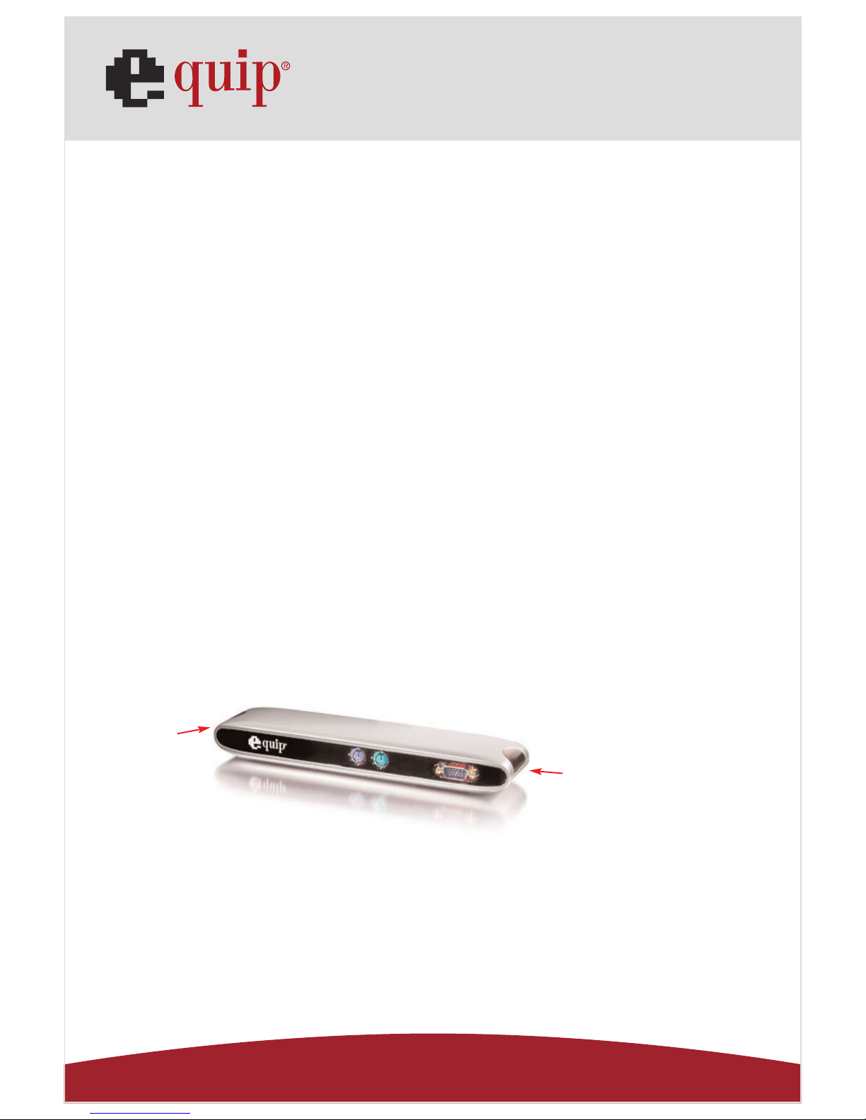
5.0 Connectors (Ref. Fig.1.1 , Fig.1.2)
1. One DB-9 RS-232 serial interface connector supports baud rates from 4800 to 115.2K.
2. One DB-25 parallel connector supports IEEE-1284 bi-directional printer port.
3. Two mini-din PS/2 ports for keyboard, mouse.
4. Three USB receptacles type A downstream ports.
5. One male and one female DB-15 VGA connectors.
6. One RJ45 10/100T base Ethernet connector.
7. One power connector
Fig. 1.1
PS/2 Keyboard PS/2 Mouse VGA in
Fig. 1.2
USB 2.0 Downstream Printer Port Serial Port RJ45 Ethernet
VGA out
Power Connector
Page 5
Manual_Page 5
www.equip-info.net
6.0 Available functions.
The available functions of USB 2.0 VGA LAN DOCK depend on the status of power supplied:
• Bus powered
1. Connect the USB/VGA combo Y cable to your PC to provide bus power.
2. When you provide bus power only, the PS/2 mouse & keyboard, RS232, printer and
USB Ethernet adapter will be enabled. However, the USB2.0 Downstream Ports can
also work under low power mode. So used of external power adaptor is recommended. (For the use of all functions)
• Externally powered
1. Connect the power adapter to provide external power.
2. When you provide external power, the USB Downstream Ports can support all USB
devices, and you can use all the functions of USB 2.0 VGA LAN DOCK.
7.0 LED Indicator (Ref. Fig.2)
• Power Indicator
The Power Indicator will turn RED as either bus power or external power is supplied,
even both of them supplied.
• LAN Indicator
1. Link/Act (RED): This LED turns on if the 10/100Mbps (100BASE-TX)
Ethernet is connected.
2.Transmission (RED): Blinking to indicate that the data is being received or transmitted
through the RJ-45 port.
LAN Indicator
Power Indicator
Fig. 2
Page 6
Manual_Page 6
www.equip-info.net
8.0 Installing USB 2.0 VGA LAN DOCK
1. This installation guide is written in accordance with different operation systems,
including Windows 98/98SE/ME, Windows 2000/XP/Vista.
2. Power on your computer and make sure that the USB & VGA ports are enabled and
working properly.
3. Put CD into CD-ROM drive of PC or Notebook.
4. Connect the power adapter into USB 2.0 VGA LAN DOCK. (For full functions)
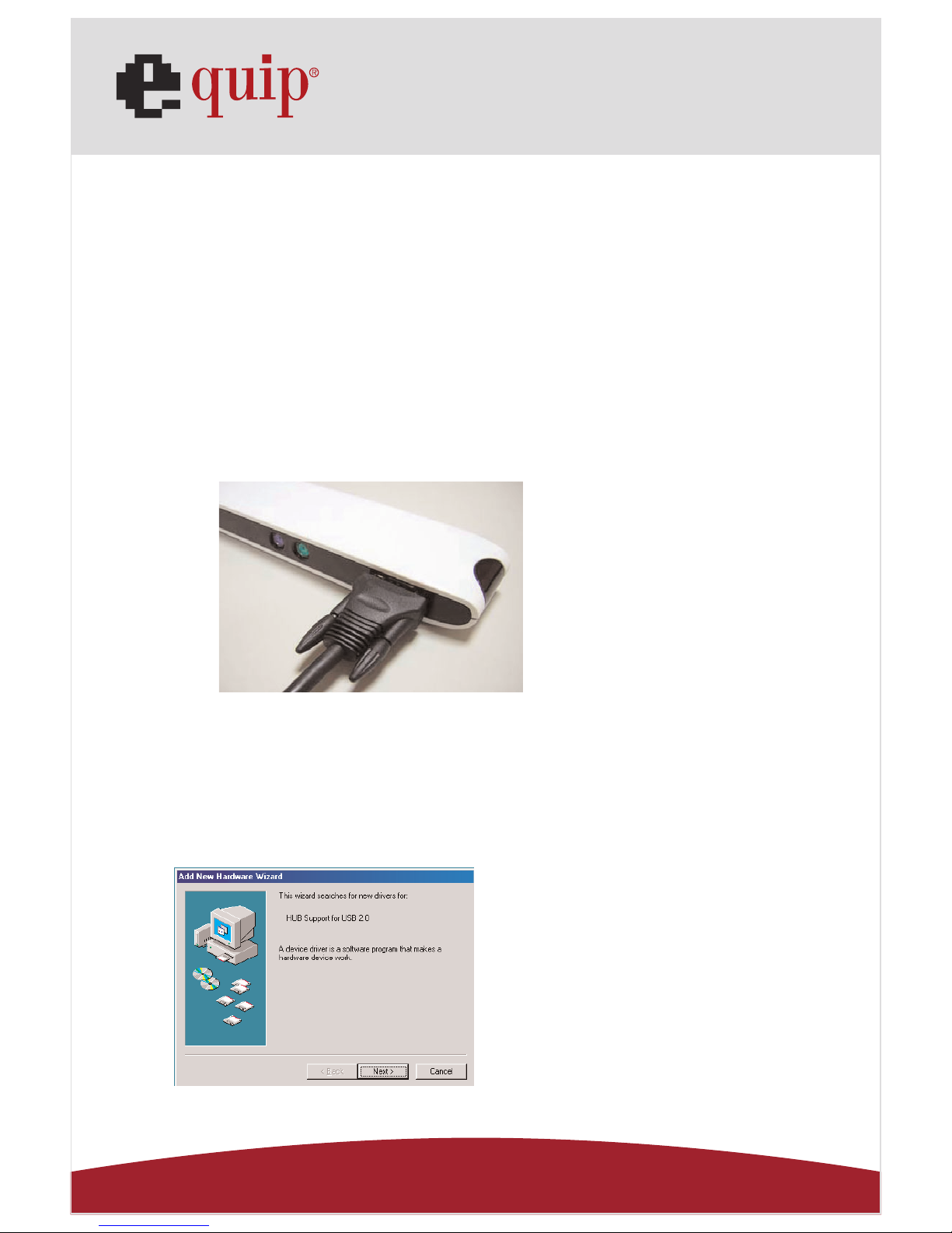
5. Connect USB 2.0 VGA LAN DOCK to the USB and VGA port on your computer with the
VGA/USB combo Y cable provided. ( as Fig.3)
6. Windows will start detecting USB devices. Please follow the related section to install
your USB 2.0 VGA LAN DOCK.
Fig. 3
9.0 Driver Installation
9.1 Win98/98SE Driver Installation
The driver installation is divided into A to F six-steps. Please install USB 2.0 VGA LAN
DOCK under Win98/SE step by step by the following instructions:
A. USB Hub Installation
Fig. Win98-A1
A1. Please insert the “Windows
98” CD into your CD-ROM drive
and press “Next” to continue.
(Ref. Fig. Win98-A1)
Page 7

Manual_Page 7
www.equip-info.net
Fig. Win98-A2
Fig. Win98-A3
Fig. Win98-A4
Fig. Win98-A5
A2. Tick “Search for the best
driver for your device” and press
“Next” to continue.
(Ref. Fig. Win98-A2)
A3. Tick “CD-ROM drive” and
press “Next” to start the searching process.
(Ref. Fig. Win98-A3)
A4. Press “Next” to start the
installation process.
(Ref Fig. Win98-A4)
A5. Press “Finish” to complete the
installation of USB HUB.
(Ref Fig. Win98-A5)
Page 8
Manual_Page 8
www.equip-info.net
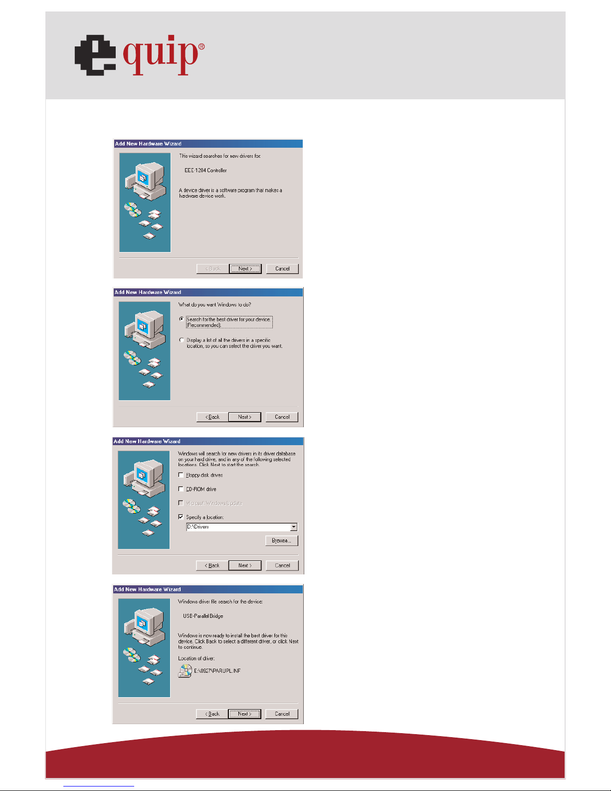
B. IEEE-1284 Controller Installation
Fig. Win98-B1
Fig. Win98-B2
Fig. Win98-B3
Fig. Win98-B4
B1. Please insert the “USB 2.0
VGA LAN DOCK” CD into your CDROM drive and press “Next” to
continue.
(Ref. Fig. Win98-B1)
B2. Tick “Search for the best
driver for your device” and press
“Next” to continue.
(Ref. Fig. Win98-B2).
B4. Press “Next” to start the
installation process.
(Ref. Fig. Win98-B4)
B3. Tick “Specify a location” and
click “Browse” to select the location of the driver folder in the
“USB 2.0 VGA LAN DOCK” CD.
Press “Next” to start the searching process.
(Ref. Fig. Win98-B3).
Page 9
Manual_Page 9
www.equip-info.net
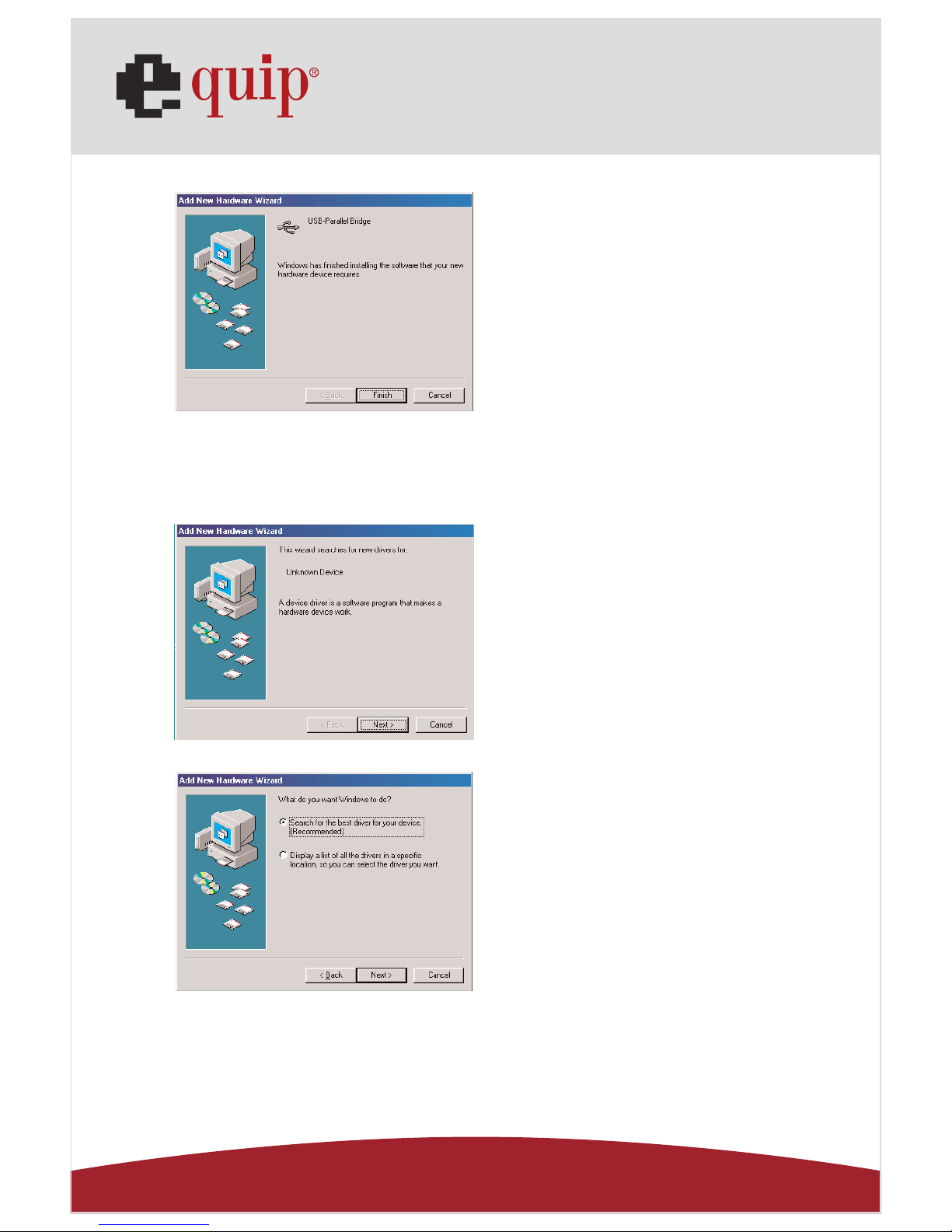
Fig. Win98-B5
C. USB to Serial Port Installation
Fig. Win98-C1
Fig. Win98-C2
B5. Press “Finish” to complete the
installation of USB-to-Parallel
Port.
(Ref. Fig. Win98-B5)
C1. Please insert the “USB 2.0
VGA LAN DOCK” CD into your CDROM drive and press “Next” to
continue.
(Ref. Fig. Win98-C1)
C2. Tick “Search for the best
driver for your device” and press
“Next” to continue.
(Ref. Fig. Win98-C2)
Page 10
Manual_Page 10
www.equip-info.net
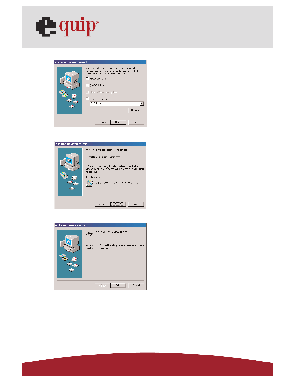
Fig. Win98-C3
Fig. Win98-C4
Fig. Win98-C5
C3. Tick “Specify a location” and
click “Browse” to select the location of the driver folder in the
“USB 2.0 VGA LAN DOCK” CD.
Click “Next” to start the searching
process.
(Ref. Fig. Win98-C3)
C4. Press “Next” to start the
installation process.
(Ref. Fig. Win98-C4)
C5. Press “Finish” to complete the
installation of USB-to-Serial Port.
(Ref. Fig. Win98-C5)
Page 11
Manual_Page 11
www.equip-info.net
D. USB Composite Device Installation
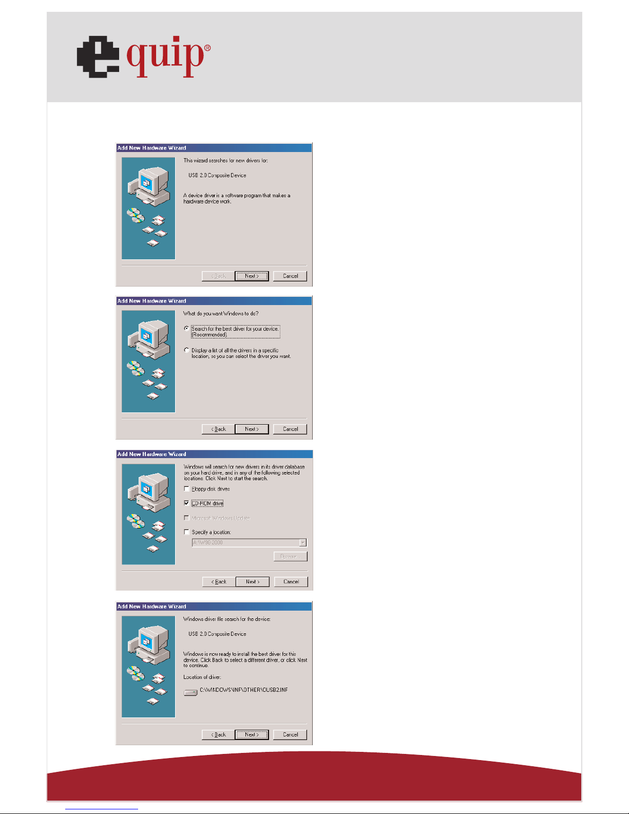
Fig. Win98-D1
Fig. Win98-D2
Fig. Win98-D3
Fig. Win98-D4
D1. Please insert the “Windows
98” CD into your CD-ROM drive
and press “Next” to continue
(Ref. Fig. Win98-D1)
D2. Tick “Search for the best
driver for your device” and press
“Next” to continue.
(Ref. Fig. Win98-D2)
D3. Tick “CD-ROM drive” and
press “Next” to start the searching process.
(Ref. Fig. Win98-D3)
D4. Press “Next” to start the
installation process.
(Ref. Fig. Win98-D4)
Page 12
Manual_Page 12
www.equip-info.net
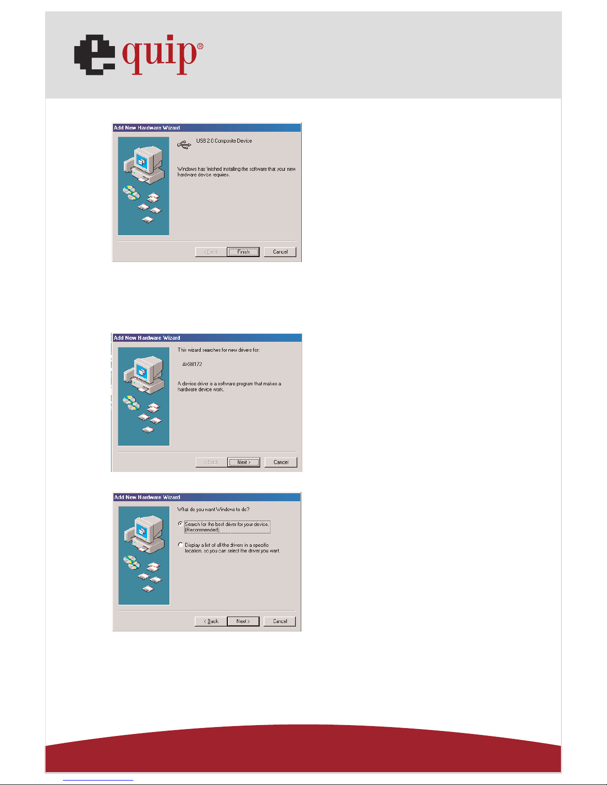
Fig. Win98-D5
E. Ethernet Port Installation
Fig. Win98-E1
Fig. Win98-E2
D5. Press “Finish” to complete the
installation of Composite Device.
(Ref. Fig. Win98-D5)
E1. Please insert the “USB 2.0
VGA LAN DOCK” CD into your CDROM drive and press “Next” to
continue.
(Ref. Fig. Win98-E1)
E2. Tick “Search for the best
driver for your device” and press
“Next” to continue.
(Ref. Fig. Win98-E2)
Page 13
Manual_Page 13
www.equip-info.net
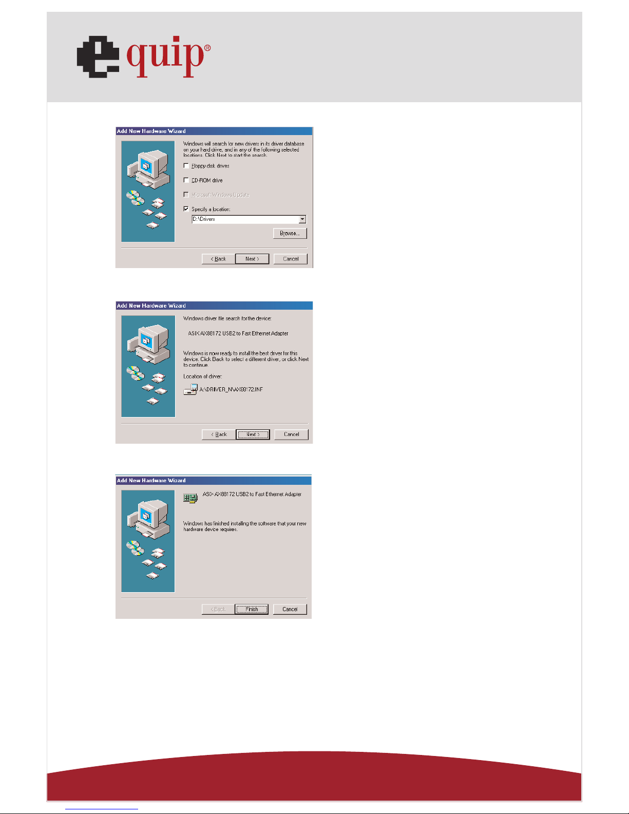
Fig. Win98-E3
Fig. Win98-E4
Fig. Win98-E5
E3. Tick “Specify a location” and
click “Browse” to select the location of the driver folder in the
“USB 2.0 VGA LAN DOCK” CD.
Press “Next” to start the searching process.
(Ref. Fig. Win98-E3)
E4. Press “Next” to start the
installation process. (Windows
might ask you to insert the
“Windows 98” CD during the
installation process).
(Ref. Fig. Win98-E4)
E5. Press “Finish” to complete the
installation of USB Ethernet adapter. (Restart Windows might
necessary).
(Ref Fig. Win98-E5)
Page 14
Manual_Page 14
www.equip-info.net
F. USB HID Device for PS/2 keyboard & mouse Installation
(This step might repeat once due to two different devices,
mouse and keyboard)
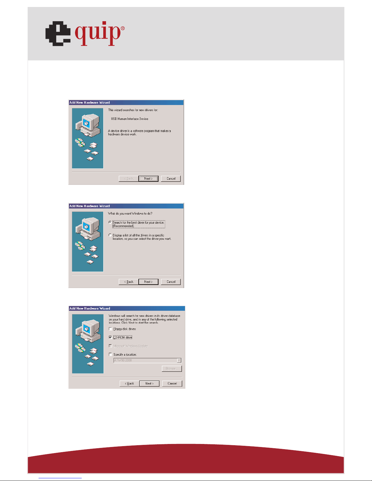
Fig. Win98-F1
Fig. Win98-F2
Fig. Win98-F3
F1. Please insert the “Windows
98” CD into your CD-ROM drive
and press “Next” to continue.
(Ref. Fig. Win98-F1)
F2. Tick “Search for the best driver
for your device” and press “Next”
to continue.
(Ref. Fig. Win98-F2)
F3. Tick “CD-ROM drive” and
press “Next” to start the searching process.
(Ref. Fig. Win98-F3)
Page 15
Manual_Page 15
www.equip-info.net
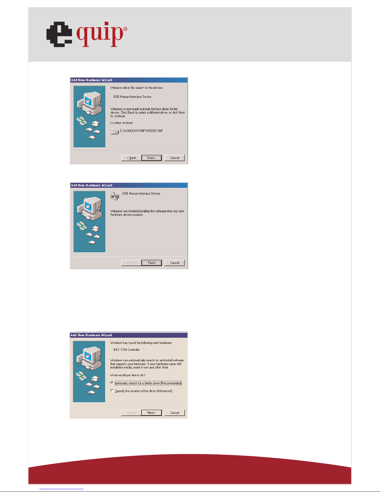
Fig. Win98-F4
Fig. Win98-F5
9.2 WinME Driver Installation
The driver installation for WinME is divided into A to C three-steps.
Please install USB 2.0 VGA LAN DOCK under WinME step by step by the
following instructions:
A. USB-to-Parallel Port Installation
Fig. WinME-A1
F4. Press “Next” to start the
installation process.
(Ref. Fig. Win98-F4)
F5. Press “Finish” to complete the
installation of HID.
(Ref. Fig. Win98-F5)
A1 Please insert the “USB 2.0
VGA LAN DOCK” CD into your CDROM drive. Tick “Automatic
search for a better driver” and
press “Next” to continue.
(Ref. Fig. WinME-A1)
Page 16
Manual_Page 16
www.equip-info.net
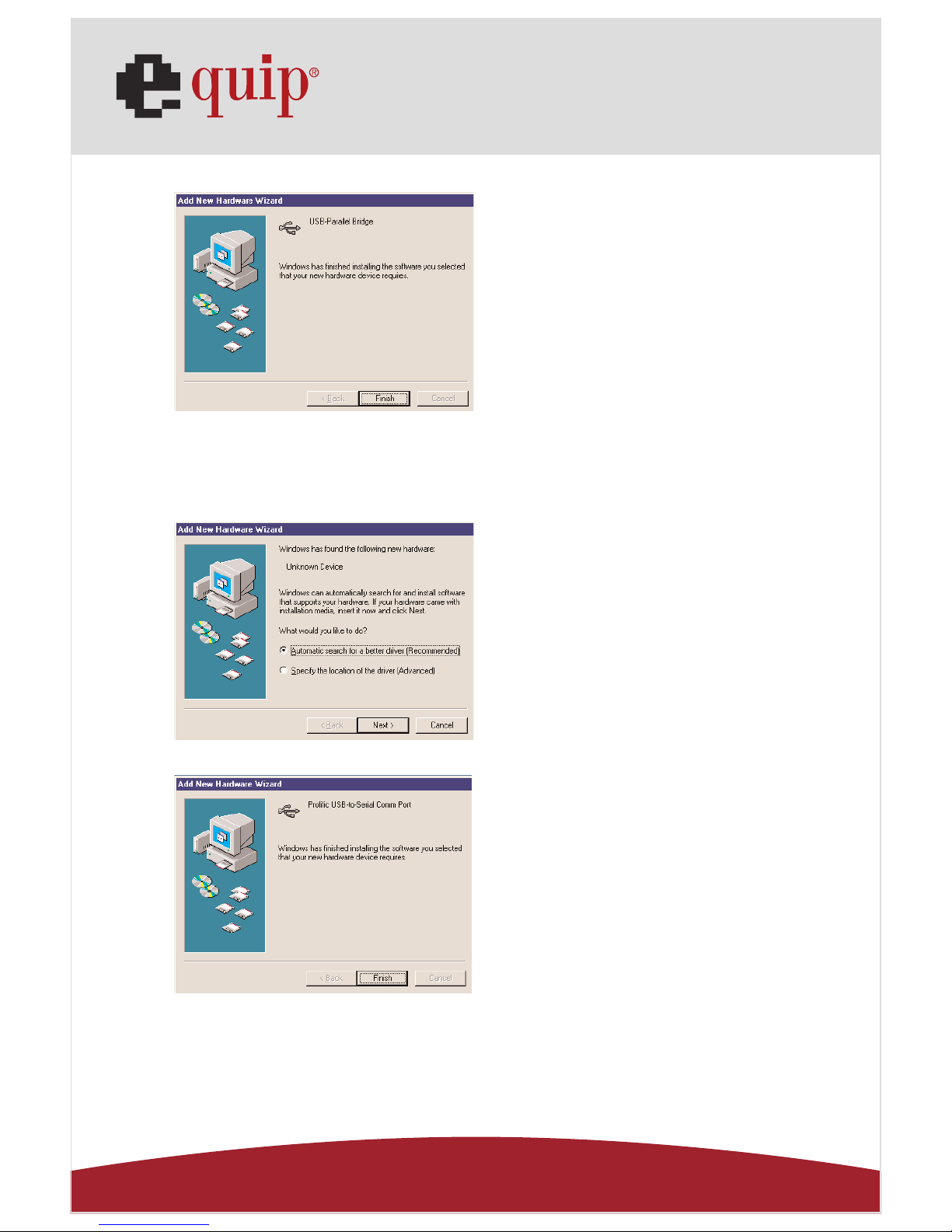
Fig. WinME-A2
B. USB-to-Serial Port Installation
Fig. WinME-B1
Fig. WinME-B2
A2. Press “Finish” to complete the
installation USB-to-Parallel Port.
(Ref. Fig. WinME-A2)
B1. Tick “Automatic search for a
better driver” and press “Next” to
continue.
(Ref. Fig. WinME-B1)
B2. Press “Finish” to complete the
installation of USB-to-Serial Port.
(Ref. Fig. WinME-B2)
Page 17
Manual_Page 17
www.equip-info.net
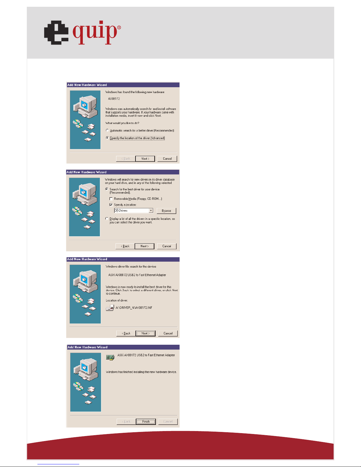
C. USB Ethernet adapter Installation
Fig. WinME-C1
Fig. WinME-C2
Fig. WinME-C3
Fig. WinME-C4
C1. Tick “Specify the location for a
better driver” and press “Next” to
continue.
(Ref. Fig. WinME-C1)
C3. Press “Next” to start the
installation process.
(Ref. Fig. WinME-C3)
C4. Press “Finish” to complete
the installation of USB Ethernet
adapter.
(Ref. Fig. WinME-C4)
C2. Tick “Search for the best driver for your
device” and then choose “Specify a location”. Click “Browse” to select the location
of the driver folder in the “USB 2.0 VGA
LAN DOCK” CD. Press “Next” to continue.
(Ref. Fig. WinME-C2)
Page 18
Manual_Page 18
www.equip-info.net
9.3 Win2000 Driver Installation
The driver installation for Win2000 is divided into A, B two-steps.
Please install USB 2.0 VGA LAN DOCK under Win2000 step by step by the
following instructions:
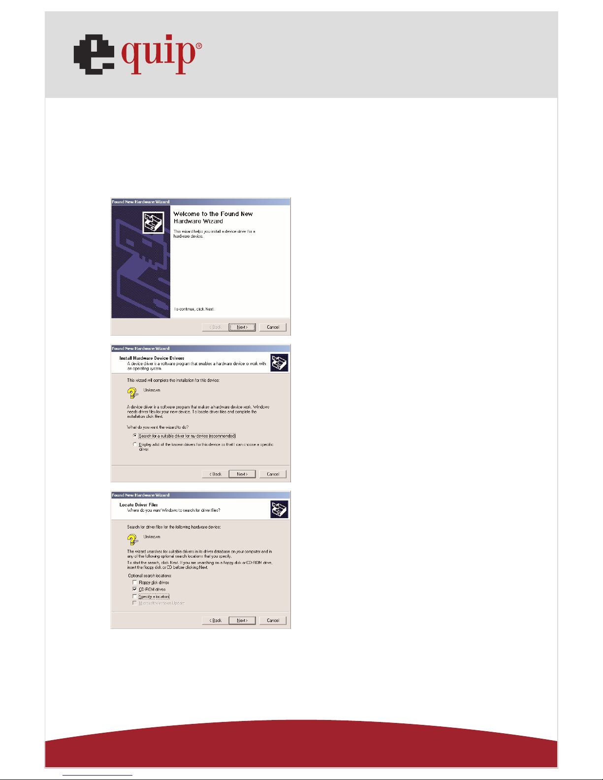
A. USB-to-Serial Port Installation
Fig. Win2k-A1
Fig. Win2k-A2
Fig. Win2k-A3
A1. Please insert the “USB 2.0
VGA LAN DOCK” CD into your CDROM drive and press “Next” to
continue.
(Ref Fig. Win2k-A1)
A2. Tick “Search for a suitable
driver for my device” and press
“Next” to continue.
(Ref Fig. Win2k-A2)
A3. Please insert “USB 2.0 VGA
LAN DOCK” CD into your CD-ROM
drive and press “Next” to start the
searching process.
(Ref Fig. Win2k-A3)
Page 19
Manual_Page 19
www.equip-info.net
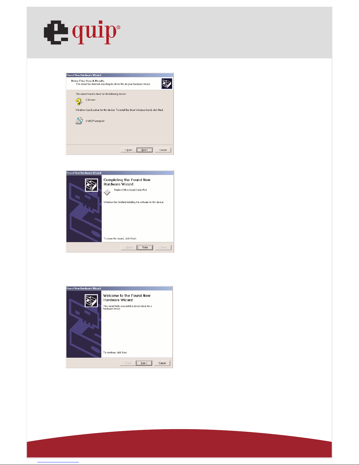
Fig. Win2k-A4
Fig. Win2k-A5
B. USB Ethernet adapter Installation
Fig. Win2k-B1
A4. Press “Next” to start the
installation process.
(Ref Fig. Win2k-A4)
A5. Press “Finish” to complete the
installation of USB-to-Serial Port.
(Ref Fig. Win2k-A5)
B1. Press “ Next” to continue.
(Ref Fig. Win2k-B1)
Page 20
Manual_Page 20
www.equip-info.net
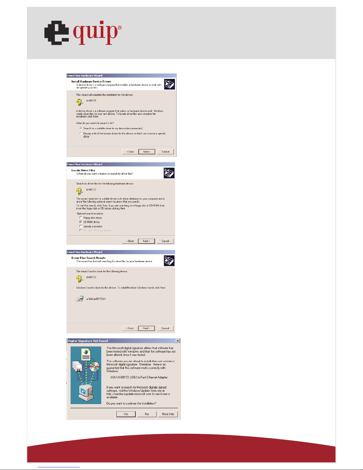
Fig. Win2k-B2
Fig. Win2k-B3
Fig. Win2k-B4
Fig. Win2k-B5
B2. Tick “Search for a suitable
driver for my device” and press
“Next” to continue.
(Ref Fig. Win2k-B2)
B3. Tick “CD-ROM drives” and
press “Next” to start the searching process.
(Ref Fig. Win2k-B3)
B4. Press “Next” to start the
installation process.
(Ref Fig. Win2k-B4)
B5. You will receive a message
stating that the software you are
installing has not passed
Windows Logo testing. But this
driver is fully compatible with
Windows 2000, so just press
“Yes” to continue.
(Ref. Fig. Win2k-B5)
Page 21
Manual_Page 21
www.equip-info.net
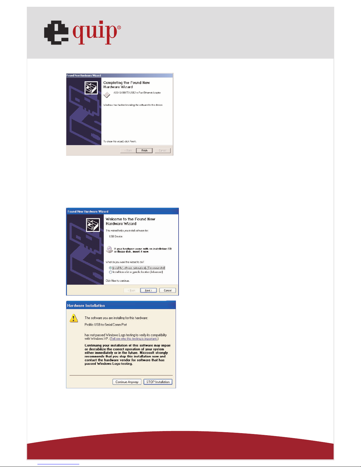
Fig. Win2k-B6
9.4 WinXP Driver Installation
Please install USB 2.0 VGA LAN DOCK under Win2000 step by step by the
following instructions:
A. Serial Port Installation
Fig. WinXP-A1
Fig. WinXP-A2
B6. Press “Finish” to complete
the installation of USB Ethernet
adapter.
(Ref. Win2k-B6)
A1. Please insert the “USB 2.0
VGA LAN DOCK” CD into your CDROM drive. Tick “Install the software automatically” and press
“Next” to continue
(Ref Fig. WinXP-A1)
A2. You will receive a message
stating that the software you are
installing has not passed Windows
Logo testing. But this driver is fully
compatible with Windows XP, so
just press “Continue Anyway” to
continue.
(Ref. Fig. WinXP-A2)
Page 22
Manual_Page 22
www.equip-info.net
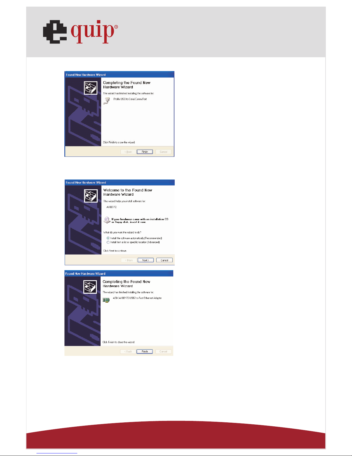
Fig. WinXP-A3
B. USB Ethernet adapter Installation
Fig. WinXP-B1
Fig. WinXP-B2
A3. Press “Finish” to complete the
installation of USB-to-Serial Port.
(Ref Fig. WinXP-A3)
B1. Tick “Install the software
automatically” and press “Next”
to continue
(Ref Fig. WinXP-B1)
B2. Press “Finish” to complete
the installation of USB Ethernet
adapter.
(Ref Fig. WinXP-B2)
Page 23
Manual_Page 23
www.equip-info.net
9.5 WinVista Driver Installation
Please install USB 2.0 LAN DOCK under Windows Vista by followings:
To install the USB to serial port driver of the USB 2.0 DOCK, please make sure
the driver diskette/CD is inserted:
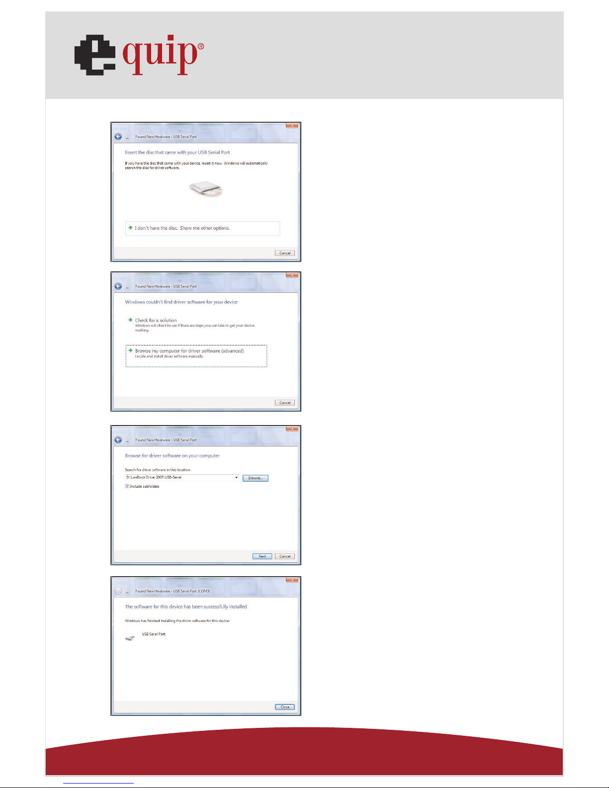
A. Serial Port Installation:
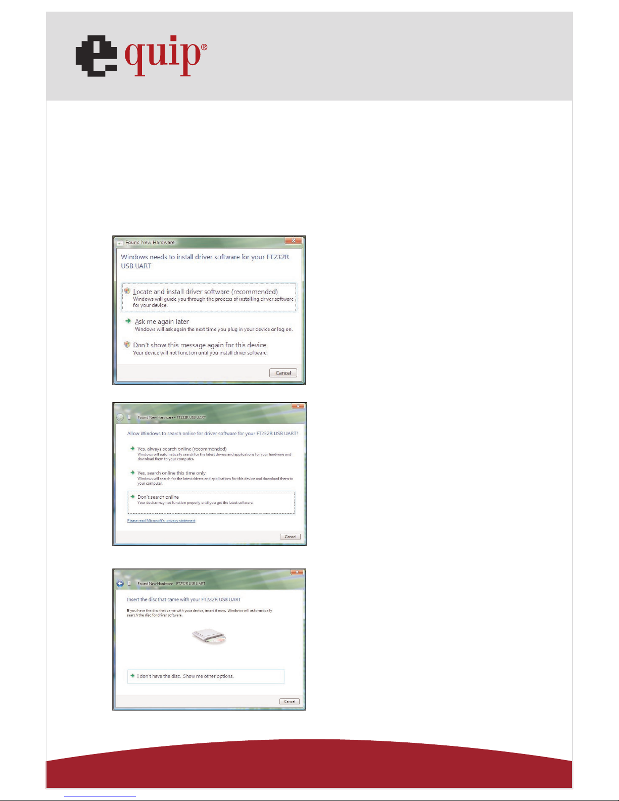
Fig. Vista-A1
Fig. Vista-A2
Fig. Vista-A3
A1. Please insert the“USB 2.0
LAN DOCK”CD into your CD-ROM
drive. Click “Locate and install
driver software (recommended)”
to continue.
(Ref. to Fig. Vista-A1)
A2. Click “Don’t search online”
to continue.
(Ref. to Fig. Vista-A2)
A3. If you driver source is not in
CD-ROM, please click “I don’t
have the disc. Show me other
options” to continue.
(Ref. to Fig. Vista-A3)
Page 24
Manual_Page 24
www.equip-info.net
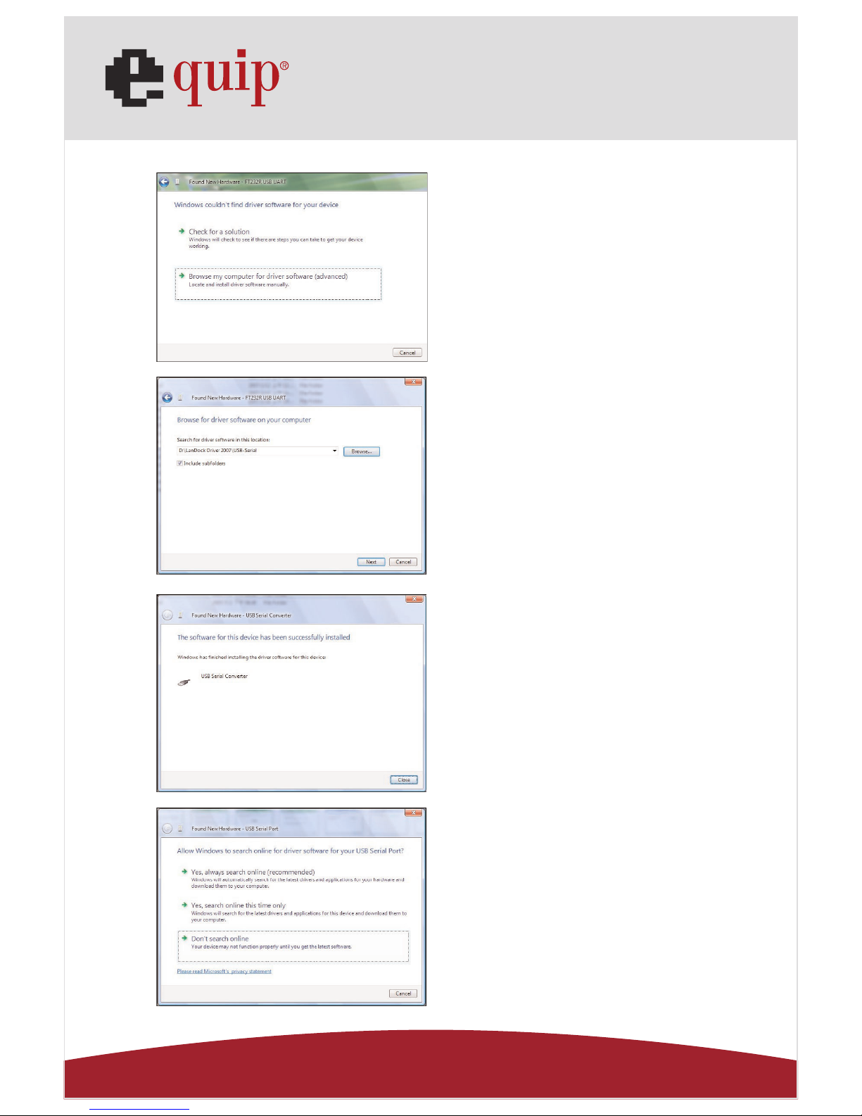
Fig. Vista-A4
Fig. Vista-A5
Fig. Vista-A6
Fig. Vista-A7
A4. Click “Browse my computer
for driver software (advanced)”
to continue.
(Ref. to Fig. Vista-A4)
A5. Browse the driver location,
and click ”Next” to continue.
(Ref. to Fig. Vista-A5)
A6. Click “Close” to finish the
“USB Serial Converter”
installation.
(Ref. to Fig. Vista-A6)
A7. When “USB Serial Port”
found, click “Don’t search online”
to continue.
(Ref. to Fig. Vista-A7)
Page 25
Manual_Page 25
www.equip-info.net
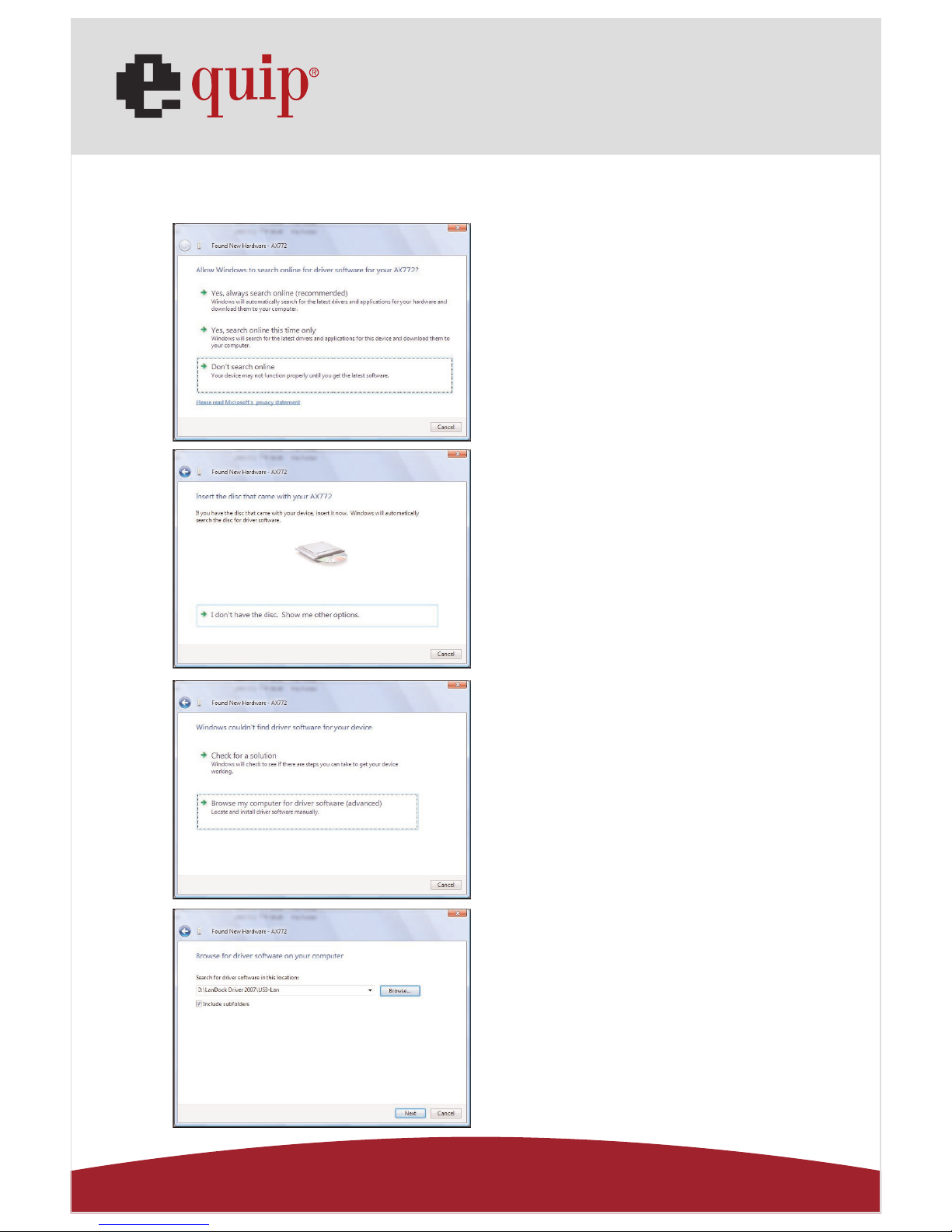
Fig. Vista-A8
Fig. Vista-A9
Fig. Vista-A10
Fig. Vista-A11
A8. If you driver source is not in
CD-ROM, please click “I don’t
have the disc. Show me other
options” to continue.
(Ref. to Fig. Vista-A8)
A9. Click “Browse my computer
for driver software (advanced)” to
continue.
(Ref. to Fig. Vista-A9)
A10. Browse the driver location,
and click ”Next” to continue.
(Ref. to Fig. Vista-A10)
A11. Click “Close” to finish
the “USB Serial Converter”
installation.
(Ref. to Fig. Vista-A11)
Page 26
Manual_Page 26
www.equip-info.net
B. USB Ethernet adapter Installation
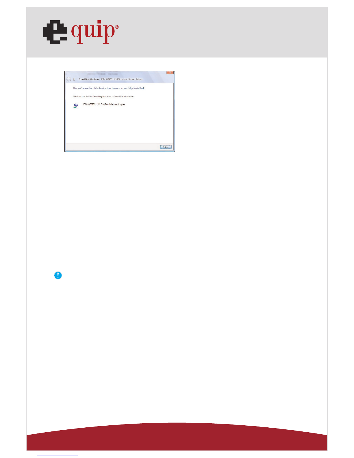
Fig. Vista-B1
Fig. Vista-B2
Fig. Vista-B3
Fig. Vista-B4
B1. When USB Ethernet adapter
“AX772” found, click “Don’t
search online” to continue.
(Ref. to Fig. Vista-B1)
B2. If you driver source is not in
CD-ROM, please click “I don’t
have the disc. Show me other
options” to continue.
(Ref. to Fig. Vista-B2)
B3. Browse the driver location,
and click ”Next” to continue.
(Ref. to Fig. Vista-B3)
B4. Browse the driver location,
and click ”Next” to continue.
(Ref. to Fig. Vista-B4)
Page 27
Manual_Page 27
www.equip-info.net
Fig. Vista-B5
10.0 Things you need to know
• Before connecting the printer to the parallel port of USB 2.0 VGA LAN DOCK, the printer driver must be installed on your computer in advance, otherwise it might print
unknown format of characters.
• Please refer to "Setting Up the Printer Device" section to connect your printer to the
USB 2.0 VGA LAN DOCK.
• For modem users, please install the modem driver manually before connecting the
modem to the converter, otherwise it might operate unexpectedly.
• Please refer to "Setting Up the HyperTerminal with USB to serial port" section as an
example of routing your COM port setting.
For the laptop computer users :
You have to follow your user’s reference guide for your computer which provided by your
computer manufacture, and set up the VGA output to your extra VGA port properly. The
USB 2.0 VGA LAN DOCK does not provide the feature of second display card, but just
repeat your VGA display from your computer and let you set up the working environment
fast without lost time.
B5. Press “Finish” to complete the
installation of the USB Ethernet
adapter.
(Ref. to Fig. Vista-B5)
Page 28
Manual_Page 28
www.equip-info.net
Congratulations!
You have finished installing USB 2.0 VGA LAN DOCK.
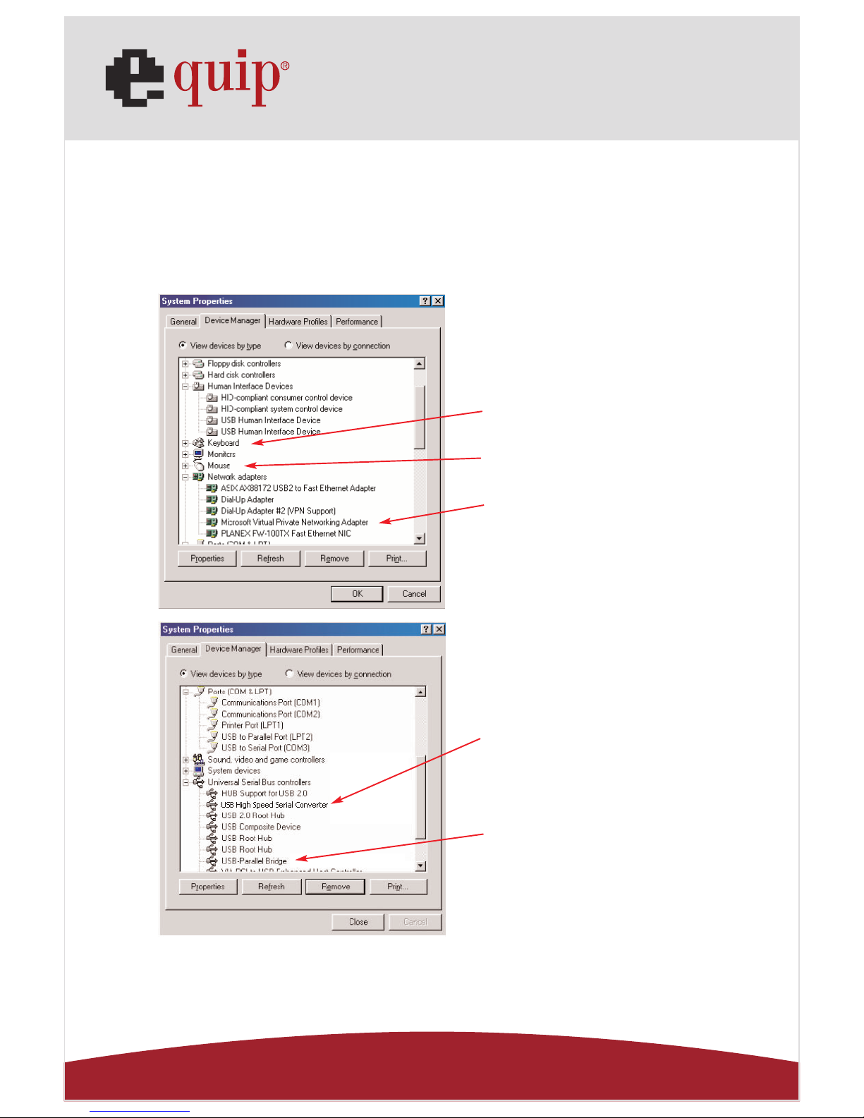
Please click on Start, Settings, Control Panel, double-click System, and Device Manager.
Please double check “Human Interface Devices”, “Keyboard”, “Mouse”, “Network adapters”, “Ports”, and “Universal serial bus controller” on the dialog box and see if they are
working properly. (Ref. Fig.4, 5)
Fig. 4
Fig. 5
USB to Serial
USB to Parallel
Keyboard
Mouse
Ethernet
Page 29
Manual_Page 29
www.equip-info.net
11.0 Set Up the Printer Device
Follow the steps below to connect your printer to the USB 2.0 VGA LAN DOCK
with your PC:
11.1 For Windows 98/98SE/ME:
1. Connect the USB 2.0 VGA LAN DOCK to your printer with the parallel cable and then
turn on the printer.
2. Connect the USB 2.0 VGA LAN DOCK to the USB port on your computer with the
USB2.0 transfer cable provided.
3. Please go to Start, Settings, Control Panel, double click System, and Device Manager.
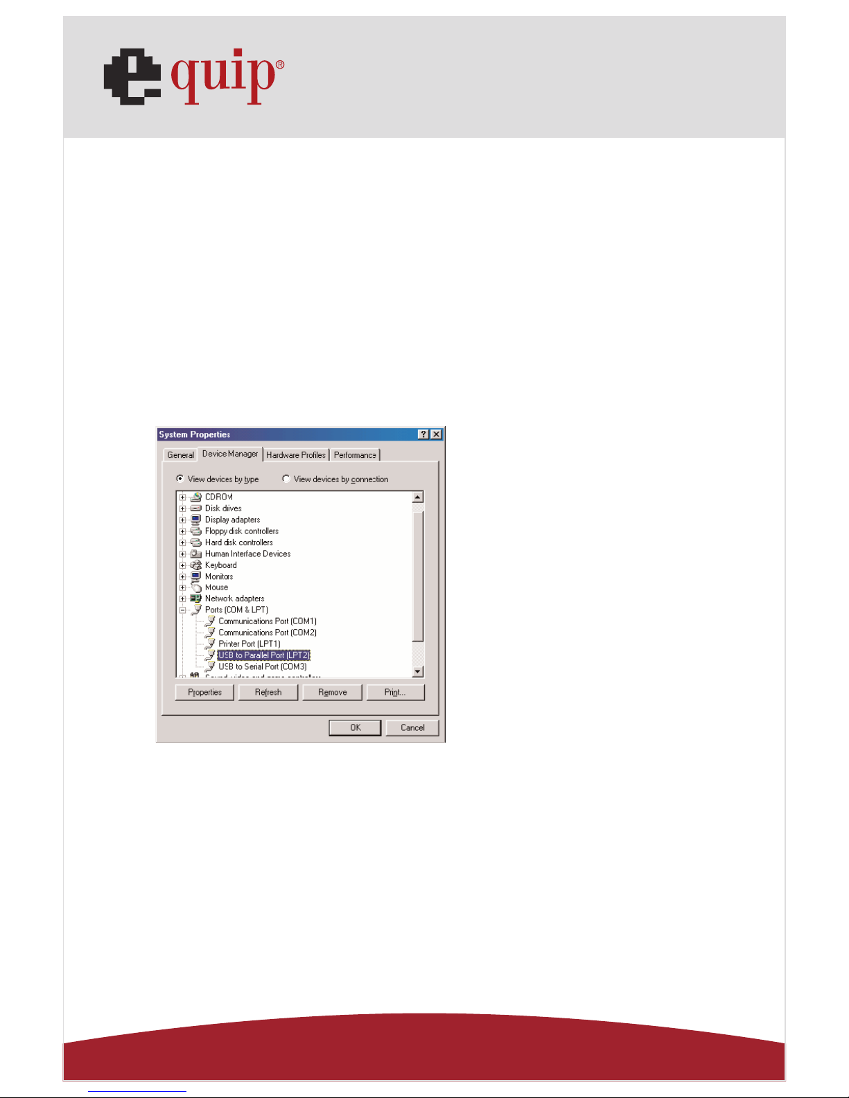
Check Ports on the dialog box and see which printer ports the “USB-to-Parallel Port” is
located. The following example is located as LPT2. (Ref. Fig.6)
Fig. 6
4. If you have installed a printer device before, go to Start, Settings, and Printers. Rightclick the default-installed printer and choose Properties. The Properties dialog box of
the installed printer will appear on your screen.
Page 30
Manual_Page 30
www.equip-info.net
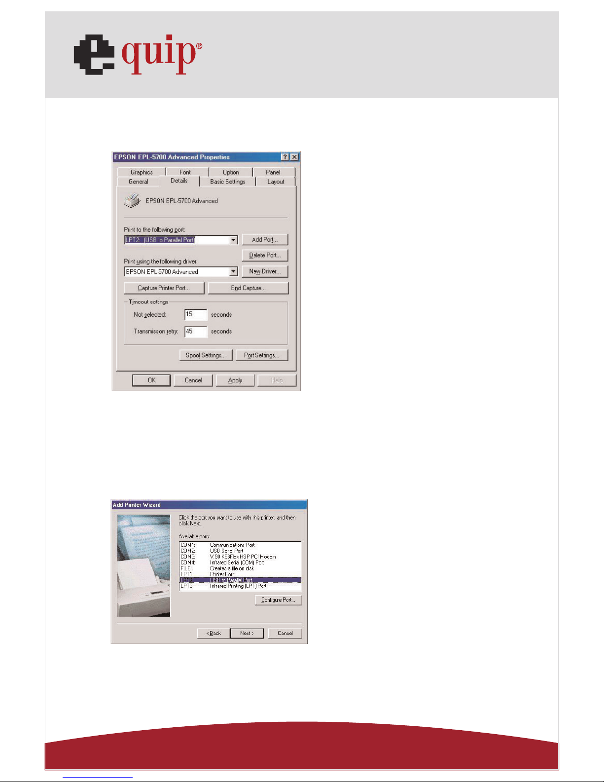
5. Click Details folder tab and change the printer port to LPT2:
USB-to- Parallel Port. (Ref. Fig.7)
Fig. 7
6. If you do not have a printer installed yet, go to Start, Settings, Printers, and choose Add
Printer. The Add Printer Wizard will start and assist you to install a new printer device.
Select the printer manufacturer and model name from the list provided by the wizard or
use the printer driver diskette came with your printer.
7. Windows will ask you which port the printer will be used, choose LPT2: USB to Parallel
Port. (Ref. Fig.8)
Fig. 8
Follow the instructions to complete the installation. Run Print Test Page to see if the printer is working without any problem.
Page 31
Manual_Page 31
www.equip-info.net
11.2 For Windows 2000/XP/Vista:
1. Connect the USB 2.0 VGA LAN DOCK to your printer with the parallel cable and then
turn on the printer.
2. Connect the USB 2.0 VGA LAN DOCK to the USB port on your computer with the USB
2.0 transfer cable provided.
3. If you have installed a printer device before, go to Start, Settings, and Printers. Rightclick the default-installed printer and choose Properties. The Properties dialog box of
the installed printer will appear on your screen.
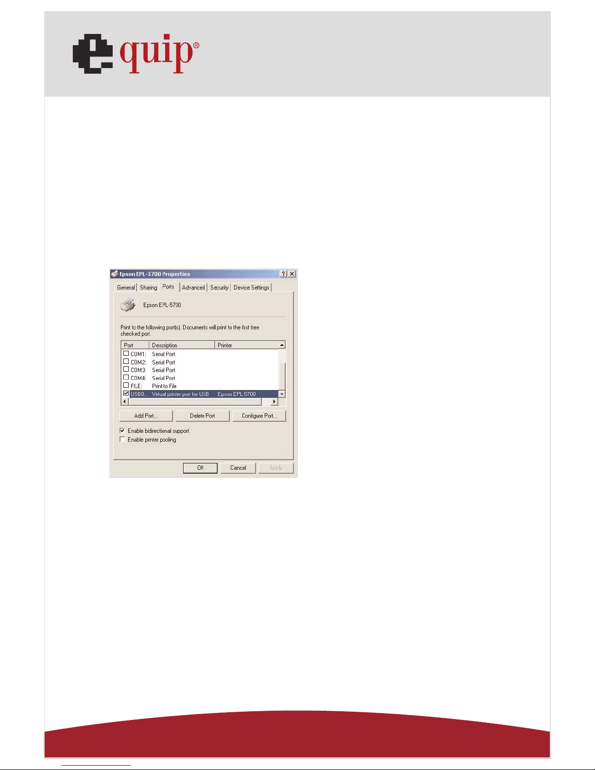
4. Click Ports folder tab and change the printer port to USB001: (Virtual printer port for
USB). (Ref. Fig.9)
Fig. 9
5. If you do not have a printer installed yet, click on Start, Settings, Printers and choose
Add Printer. The Add Printer Wizard will start and assist you to install a new printer
device. Select the printer manufacturer and model name from the list provided by the
wizard or use the printer driver diskette came with your printer.
Page 32
Manual_Page 32
www.equip-info.net
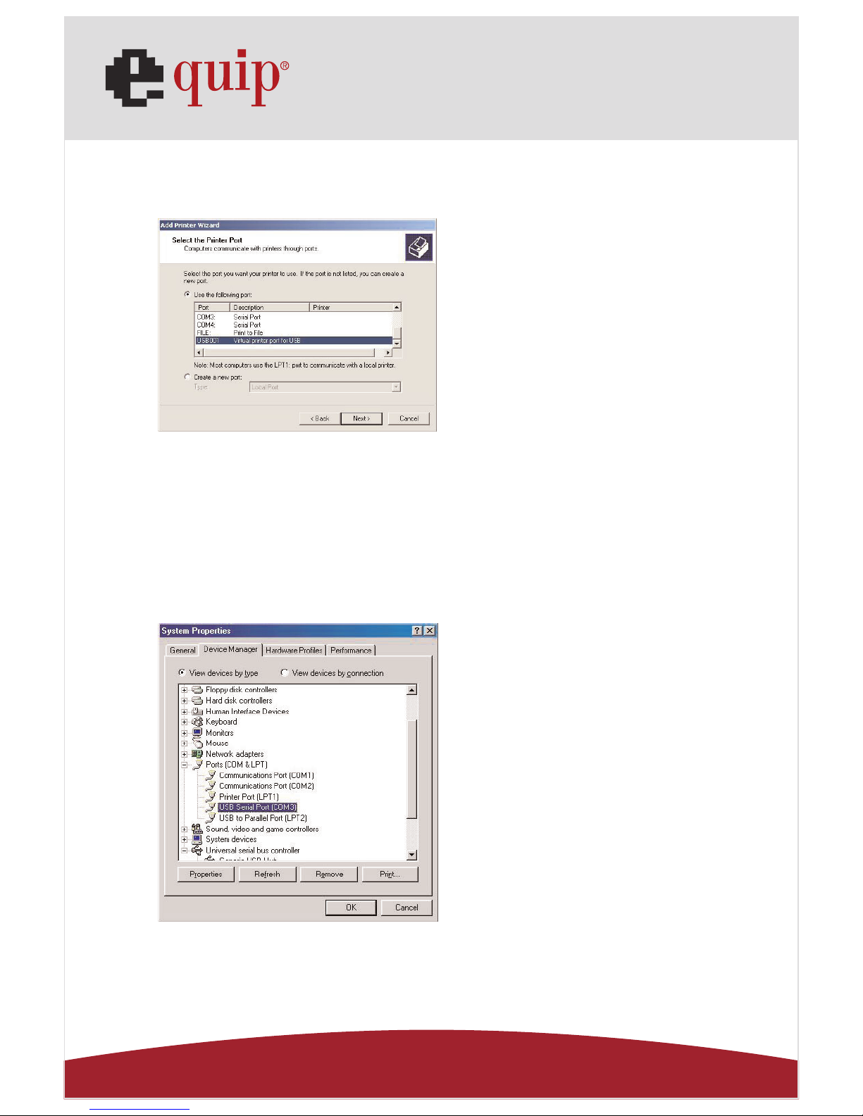
6. Windows will ask you which port the printer will be used, choose USB001: (Virtual
printer port to USB). (Ref. Fig.10)
Fig. 10
12.0 Set up the HyperTerminal with USB to serial port
1. Make sure that HyperTerminal is installed in your system. If not, please go to Start,
Settings, and Control Panel. Double click Add/Remove Programs, choose Windows
Setup page, Communications, click Details button and enable HyperTerminal to install
the program to your Windows system.
2. Go to Start, Settings, Control Panel, double click System, and click on Device Manager.
Check which COM port is located by USB to serial port. (Ref. Fig.11)
Fig. 11
Page 33
Manual_Page 33
www.equip-info.net
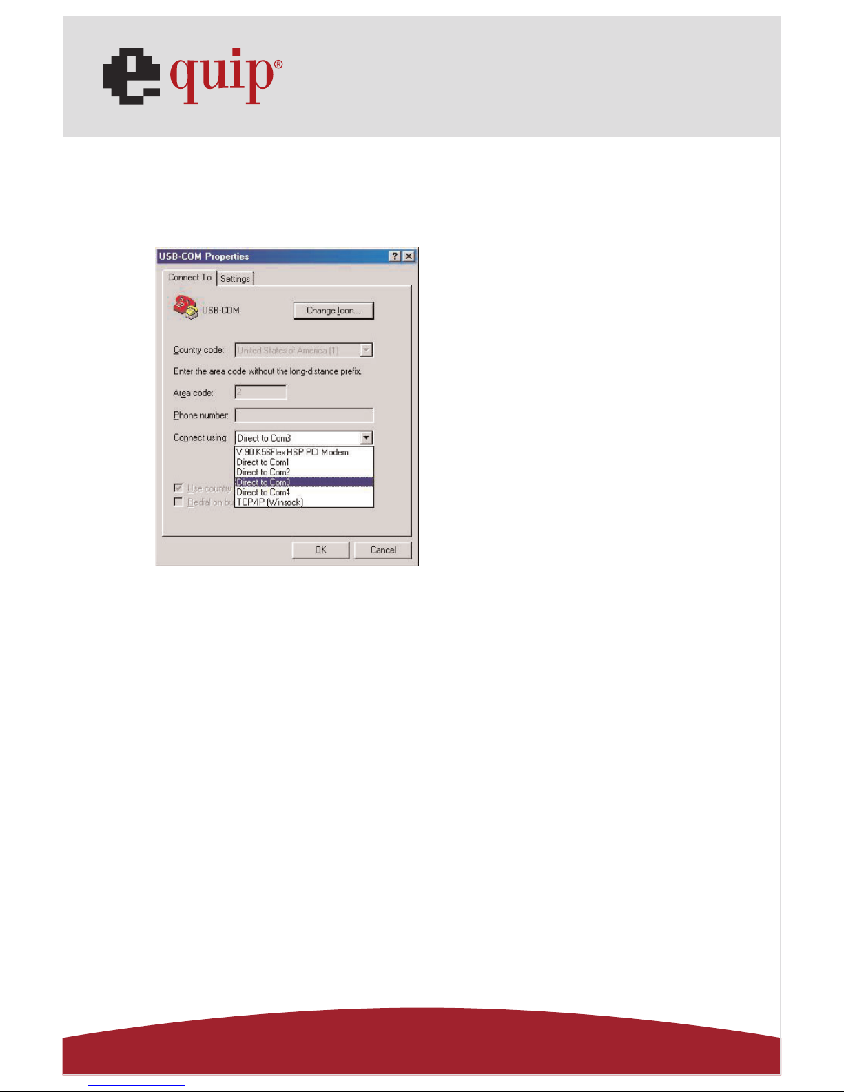
3. If you have setup HyperTerminal before, please go to Start, Programs, Accessories,
Communications, HyperTerminal. Click File and choose Properties. The Properties dialog
page will appear on your screen. If it is your first time to setup HyperTerminal, you will
see the following page during the setup procedure. (Ref. Fig.12)
Fig. 12
4. Click the Connect using item to indicate the proper COM port, which appeared in step
1. Follow the instructions to complete the setup.
13.0 Uninstalling USB 2.0 VGA LAN DOCK
If you want to remove USB 2.0 VGA LAN DOCK and its driver, you can uninstall it by the
following steps:
13.1 Remove the device
1. Please Unplug the USB cable.
14.0 Uninstall the driver
1. For the Window 2000/XP/Vista users: since the system has build in the USB Printer
Class driver already, so you do not need to remove the printer driver.
2. For the Window 98/SE/ME users: you have to follow the instruction to remove the
Serial, Printer and LAN driver.
Page 34
Manual_Page 34
www.equip-info.net
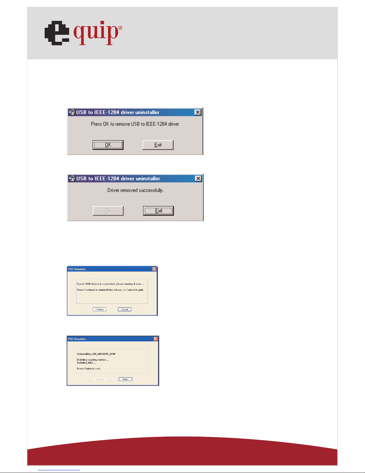
14.1 For Windows 98/SE/ME ( Remove Printer, LAN, Serial Drivers ):
1. Run Uninst.exe from the driver folder in USB 2.0 VGA LAN DOCK CD.
2. Please Press OK to remove Printer Converter. (Ref. Fig.13)
Fig. 13
3. Printer Converter had been removed. Please press Exit to continue. (Ref. Fig.14)
Fig. 14
4. Run remove_98me.exe from the driver folder in USB 2.0 VGA LAN DOCK CD to remove
the LAN driver, this program will not show any message on the screen.
5. Run FTDIUNIN.exe from the driver folder in USB 2.0 VGA LAN DOCK CD. (Ref. Fig.15)
Fig. 15
6. Please Press OK to remove Serial Converter. (Ref. Fig.16)
Fig. 16
7. Reboot your Windows system to complete.
Page 35
Manual_Page 35
www.equip-info.net
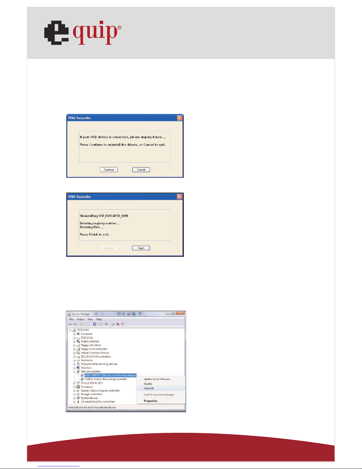
14.2 For Windows 2000/XP ( Remove LAN, Serial Driver ):
1. Run remove_xp2k.exe from the driver folder in USB 2.0 VGA LAN DOCK CD to remove
the LAN driver, this program will not show any message on the screen.
2. Run FTDIUNIN.exe from the driver folder in USB 2.0 VGA LAN DOCK CD. (Ref. Fig.17)
Fig. 17
3. Please Press “Continue” to remove Serial Converter. (Ref. Fig.18)
Fig. 18
4. Reboot your Windows system to complete.
14.3 For Windows Vista ( Remove LAN, Serial Driver ):
Fig.19
1. In device manager, right click “ASIX
AX88772 USB 2.0 to Fast Ethernet
Adapter” of “Network adapter” by
using mouse, select Uninstall to
remove the LAN driver.
(Ref. Fing. 19)
Page 36
Manual_Page 36
www.equip-info.net
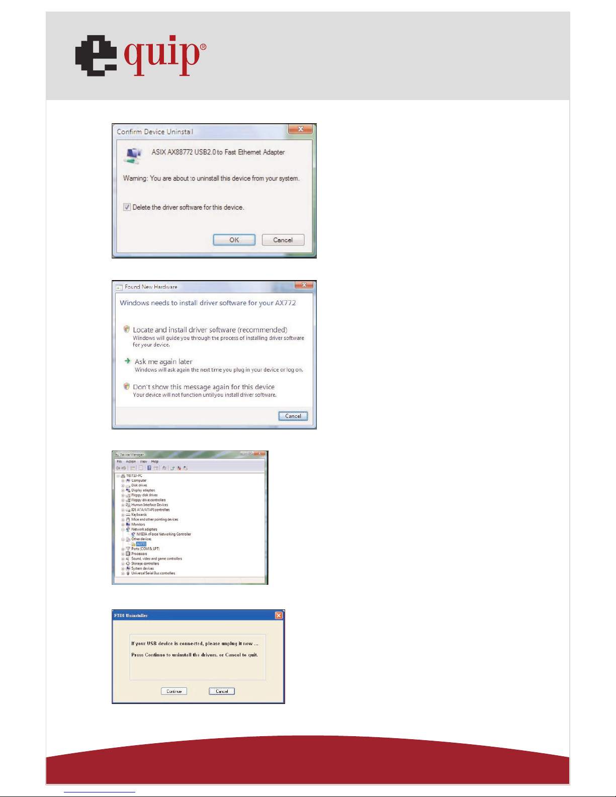
Fig.20
Fig.21
Fig.22
Fig.23
2. Enable “Delete the driver software
for the device”, and click “OK” to
continue.
(Ref. Fig.20)
3. Selct “Don’t show this message
again for this device” to continue.
(Ref. Fig.21)
4. The LAN driver is removed
successfully.
(Ref. Fig.22)
5. Run FTDIUNIN.exe from the driver
folder in USB 2.0 VGA LAN
DOCK CD. (Ref. Fig.23)
Page 37
Manual_Page 37
www.equip-info.net
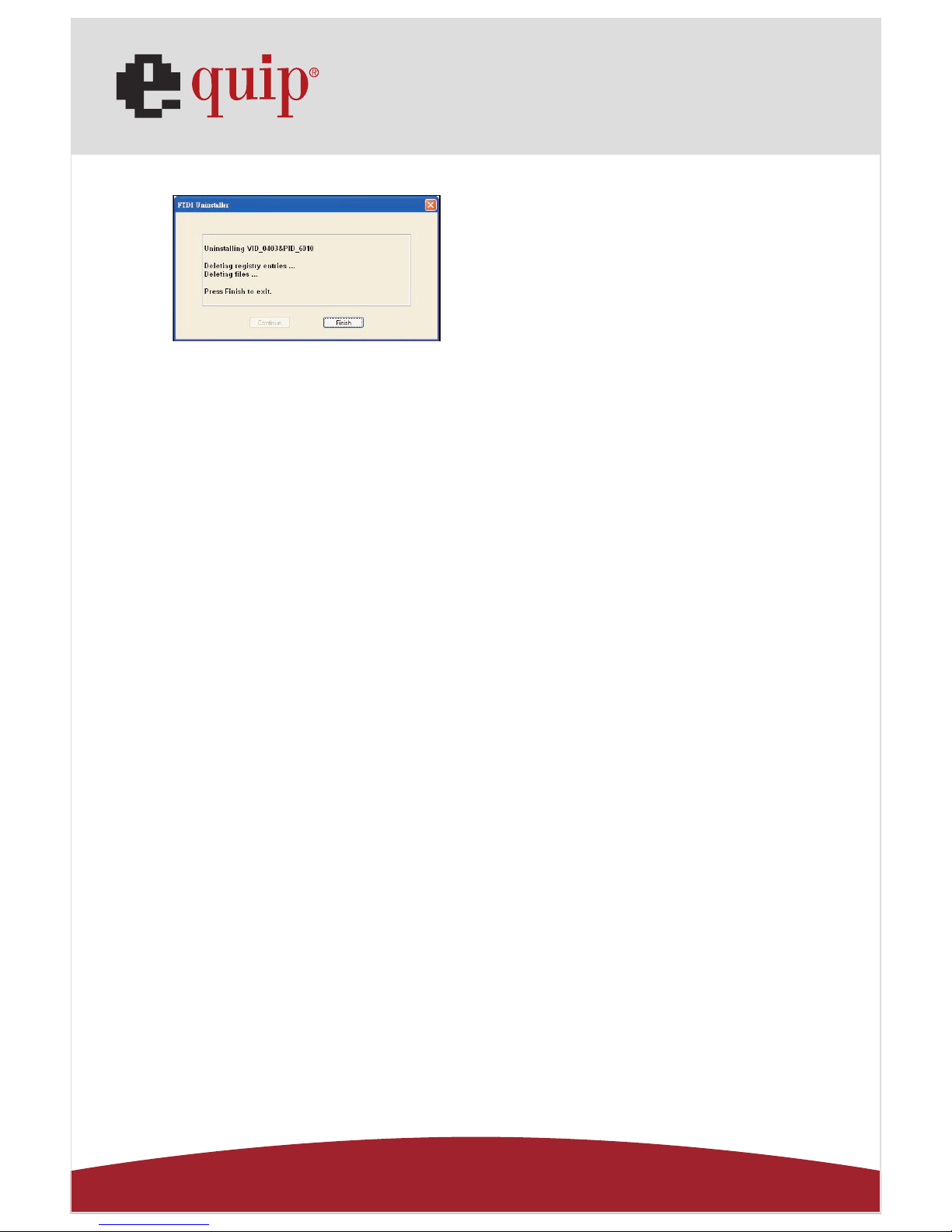
Fig.24
7. Reboot your Windows system to complete.
15.0 TROUBLE SHOOTING
Q: Installed the driver for USB 2.0 VGA LAN Dock under Windows XP ope-
ration system, there is no Pinter Port available in the device manager ,
but the other Ports ( Serial ,Mouse, Keyboard and USB) are OK .
A: The driver for USB to Printer converter on Windows 2000 and XP is not
required. Microsoft supports USB Printer class in both OS. The related
driver will be loaded Automatically by Microsoft when you plug in the
USB to Printer device. It will be created a message “printer support
device” in the device manager and also a “ virtual printer port for USB
“ in the port selection of printer setting. You may just check this item
and it will work on both system.
This is different for Windows 98 and ME. There won’t be any LPT port
generated by system as like in 98/ME . Please also refer to the user’s
manual
“Set up the Printer Device “ >> for Windows 2000 and XP .
6. Please Press “Continue” to remove
Serial Converter.
(Ref. Fig.24)
Page 38

Manual_Page 38
www.equip-info.net
16.0 APPLICATION NOTE
1. USB 2.0 VGA LAN DOCK normally derives its own power from PC Host. When only the
Host power is supplied, the Power LED will turn RED, and the serial, parallel, keyboard,
mouse, Ethernet and 3 downstream ports can operate without the external power
adapter.
2. Please note that if the external power adaptor is not be used and heavy power consumption USB device is connected, the 3 downstream ports may not function normally.
Therefore the used of external power adaptor is highly recommend. You may use the
external power by connecting an external 5 voltage, 2A DC power that is UL, CE, Tmark or locally approved. For Polarity, see the following:
3. Unknown Device:
If the installation process is completed and some of the devices still don't work, please
click on Start, Settings, Control Panel, double-click System, and Device Manager. Check
“Human Interface Devices”, “Keyboard”, “Mouse”, “Network adapters”, “Ports”, and
“Universal serial bus controller” on the dialog box and see if “Unknown device” appears on the screen. You need to right-click the “Unknown device” and choose Remove to
remove it. Then choose Refresh to re-detect the device. (You might need to install the
device driver once again so please follow the same installation procedures as section
9.0). After trying the above procedures and your device still cannot work, please contact the technical support at your local distributor.
Disclaimer
Information in this document is subject to change without notice. The manufacturer does
not make any representations or warranties (implied or otherwise) regarding the accuracy
and completeness of this document and shall in no event be liable for any loss of profit or
any other commercial damage, including but not limited to special, incidental, consequential, or other damages.
No part of this document may be reproduced or transmitted in any form by any means,
electronic or mechanical, including photocopying, recording or information recording and
retrieval systems without the express written permission of the manufacturer.
All brand names and product names used in this document are trademarks, or registered
trademarks of their respective holders.
Page 39

Manual_Page 39
www.equip-info.net
FCC Statement
This device generates and uses radio frequency and may cause interference to radio and
television reception if not installed and used properly. This has been tested and found to
comply with the limits of a Class B computing device in accordance with the specifications in Part 15 of the FCC Rules. These specifications are designed to provide reasonable
protection against such interference in a residential installation. However, there is no
guarantee that interference will not occur in a particular installation. If this device does
cause harmful interference to radio or television reception, which can be determined by
plugging the device in and out, the user can try to correct the interference by one or more
of the following measures:
• Reorient or relocate the receiving antenna.
• Increase the separation between the device and receiver.
• Connect the computer into an outlet on a circuit different from that to which the receiver is connected.
• Consult the dealer or an experienced radio/TV technician for help.
 Loading...