

Equinox Systems SSM-8I, SSM-12I, SSM-24I, SSM-12E, SSM-24E Hardware Installation & Reference Manual
...Page 1
e
Hardware
Installation &
Reference
Manual
Megaport SS
Serial I/O Board
Series
PN 560092/B
March 1996
Page 2

ii Equinox Megaport SS Board Series Hardware Manual
○○○○○○○○○○○○○○○○○○○○○○○○○○○○○○○○○○○○○○○○○○○○○○○○○○○○○
Notice
© 1995, 1996 Equinox Systems Inc. All rights reserved. Reproduction without permission prohibited.
Equinox, Megaport, Megaplex, and SuperSerial are registered trademarks of Equinox Systems Inc. All other brands and product names
are trademarks of their respective holders.
Equinox makes no representations or warranties with respect to the
contents hereof and specifically disclaims any implied warranties of
merchantability or fitness for any particular purpose. Information is
subject to change without notice and does not represent a commitment
on the part of Equinox Systems Inc.
The equipment has been tested and found to comply with the limits for
Class A digital devices, pursuant to Part 15 of the FCC rules. These
limits are designed to provide reasonable protection against harmful
interference when the equipment is operated in a commercial environment. This equipment generates, uses, and can radiate radio frequency
energy and, if not installed and used in accordance with the instruction
manual, may cause harmful interference to radio communications.
Operation of this equipment in a residential area is likely to cause
harmful interference in which case the user will be required to correct
the interference at his own expense.
NOTE: The manufacturer is not responsible for any radio or TV
interference caused by unauthorized modifications to this equipment.
Such modifications could void the user’s authority to operate the
equipment.
Megaport SS, Serial I/O Board Series, Hardware Manual
560092/B (March 1996)
Equinox Systems Inc.
One Equinox W a y
Sunrise, Florida 33351-6709
(954) 746-9000
Fax: (954) 746-9101
BBS: (954) 746-0282
e-mail: [email protected]
FCC Notice
Page 3

Table of Contents iii
Manual Organization
This manual is comprised of three chapters and one appendix.
Chapter 1. Overview
This chapter describes the Equinox family of Megaport SS
Boards.
Chapter 2. Installation
Chapter 2 describes the Megaport SS Board installation.
Chapter 3. Port to Device Cabling
The Megaport SS Boards support a wide variety of
terminals, printers and modems. Chapter 3 describes
the SSM cabling options.
Appendix A. Support Procedures
Appendix A describes the steps you would follow to
receive technical support and to report problems with
this documentation.
Index
Page 4

Contents
1. Overview
Megaport SS Boards........................................................1-1
Software Driver ................................................................1-2
Adaptor Cable ..................................................................1-3
2. Installation
Assigning the ISA I/O Base Address ................................2-1
Address Log.....................................................................2-3
Board Installation .............................................................2-3
EISA System Setup..........................................................2-4
Micro Channel System Setup...........................................2-5
Installing the Round Cable ...............................................2-6
Equinox Wiring Accessories .............................................2-6
3. Port to Device Cabling
Port Signal Names ...........................................................3-2
Conversion to RS-232 Signal Names...............................3-2
Telco Connector Pinouts ..................................................3-3
Wiring to Terminal Devices...............................................3-5
DB-25 Wiring....................................................................3-7
Modular Wiring.................................................................3-8
A. Support Procedures
Technical Support Procedures ........................................ A-1
Document Support Procedures....................................... A-2
Index
Page 5

e
Hardware
Installation &
Reference
Manual
Megaport SS
Serial I/O Board
Series
PN 560092/B
March 1996
Page 6

Page 7

One Equinox Wa y
Sunrise, Florida 33351
Tel. 954-746-9000 FAX 954-746-9101
BBS 954-746-0282
e-mail: [email protected]
FTP site ftp.equinox.com
e
Page 8

viii Equinox Megaport SS Board Series Hardware Manual
Page 9
Overview 1-1
1
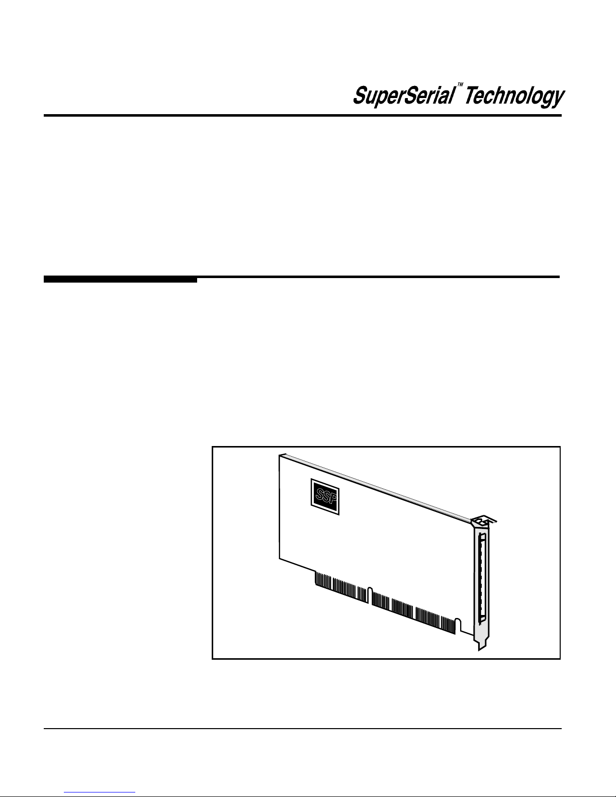
Figure 1-1. Megaport SS Board
Overview
Equinox Megaport SS Boards are intelligent, high-speed (up to
115K bps) multiport boards providing high performance serial I/
O solutions for ISA, EISA and Micro Channel bus systems. All
port interfaces are standard RS-232 with modem control and
voltage surge protection.
The Megaport SS Board (shown in Figure 1-1) occupies a slot in
the host computer and provide the intelligent functions to "offload" the CPU serial communications processing tasks. Boards
are available for ISA, EISA and Micro Channel bus systems and
are compatible with operating systems using UNIX and LAN
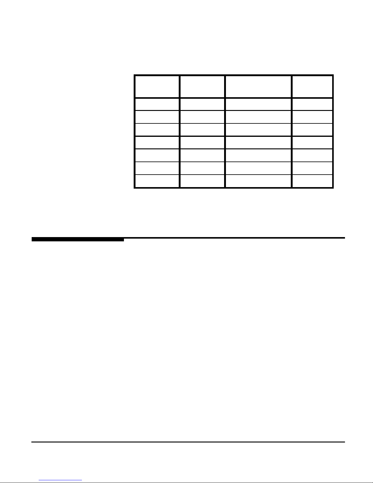
applications. Table 1-1 lists the various models and characteristics of the Megaport SST Boards available from Equinox.
SSP
Megaport SS
Boards
Page 10
1-2 Equinox Megaport SS Board Series Hardware Manual
Table 1-1. Megaport SS Boards
PART
NUMBER
MODEL BUS Type Ports
950267 SSM-8I ISA 8
950242 SSM-12I ISA 12
950241 SSM-24I ISA 24
950244 SSM-12E EISA 12
950243 SSM-24E EISA 24
950246 SSM-12M Micro Channel 12
950245 SSM-24M Micro Channel 24
Software Driver
All Megaport SS Boards include a software driver diskette and
installation manual. EISA and Micro Channel machines must
run their setup utility whenever a board is added or removed
from the computer. See your system documentation on how to
run these utilities. Equinox EISA .
cfg and Micro Channel .adf
files can be found in the root directory of the Equinox SST DOS
Diagnostic and Configuration Software for UNIX based systems
diskette.
Page 11
Overview 1-3
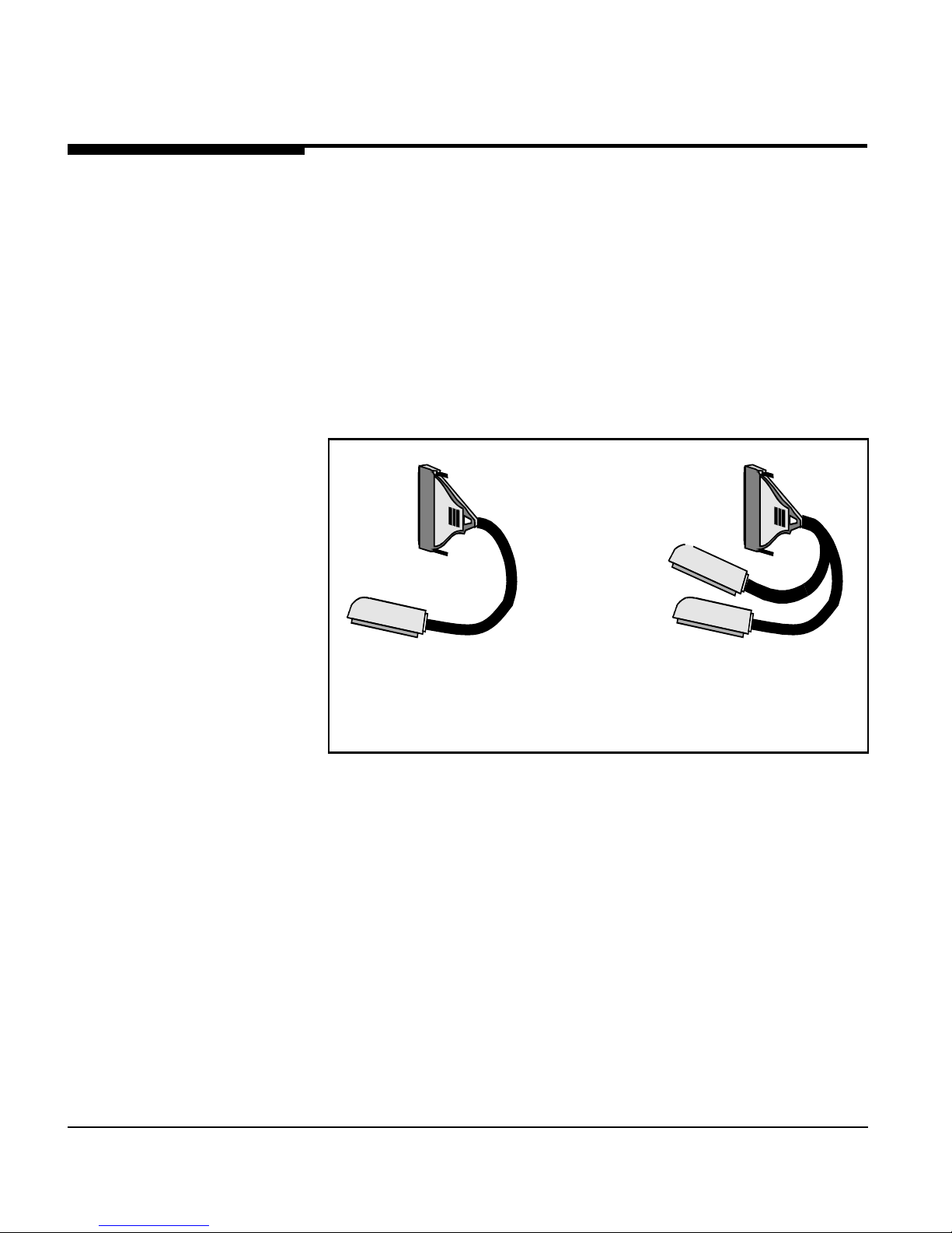
Figure 1-2. Cable used with SSM-12 and SSM-24 Megaport Boards
Cable used with
SSM-12
Megaport Board
Cable used with
SSM-24
Megaport Board
The Megaport SSM-8 board has eight 6-wire RJ-11 connectors
on the back of the board.
Included with each Megaport 12/24 SS Board is an adapter
cable. The adaptor cable is connected to the board and
terminates with one or two 50-pin telco connector (illustrated in
Figure 1-2). These connectors are attached to any one of a
variety of splitters and distribution panels for device connection.
The cable used with Model SSM-12 Megaport boards terminates
with one telco connector providing port connections for up to 12
devices. The cable used with Model SSM-24 Megaport Boards
terminates with two telco connectors and provides port
connections for up to 24 devices.
Adapter Cable
Page 12
1-4 Equinox Megaport SS Board Series Hardware Manual
Differences in
Megaport SS vs
Megaport CS
See Table 2-2 above for differences between Megaport SS and
Megaport CS serial I/O adapter cards. Note that the Equinox
Megaport SS product line supports device drivers that the
Megaport CS product line does not. Contact Equinox sales or
your Equinox reseller for more details.
Table 2-2. Megaport SS to Megaport CS Comparison
Feature Megaport SS Megaport 8/12/24 CS
Maximum Speed 115.2 kbps 38.4 kbps
Voltage Surge Protection Yes No
OS/2 Driver Support No Yes
AIX Driver Support No Yes
Solaris Driver Support No Yes
QNX Driver Support No Yes
UNIX ISA Auto Install Yes No
ISA Memory Requirements 16 K bytes 8 K + 8 K / Board
ISA I/O Address Configuration DIP Switch Header Strap
Control Signal Borrowing No Yes
DOS Diagnostics Yes No
Warranty 5 Years 3 Years
Page 13
Installation 2-1
2
Installation
The system requirements for ISA, EISA and Micro Channel Platforms
are discussed in this chapter.
Megaport SS Boards appear to the system host processor as memory.
That is, they are memory mapped devices. Each board is automatically
mapped into system memory at the time of device driver installation.
The device driver soft-configures all boards each time the system is
initialized (booted).
Assigning the ISA I/O
Base Address
This section discusses the I/O address requirements for the Megaport
SS Board installed in an ISA system. (EISA and Micro Channel system
memory requirements are discussed later in this chapter.)
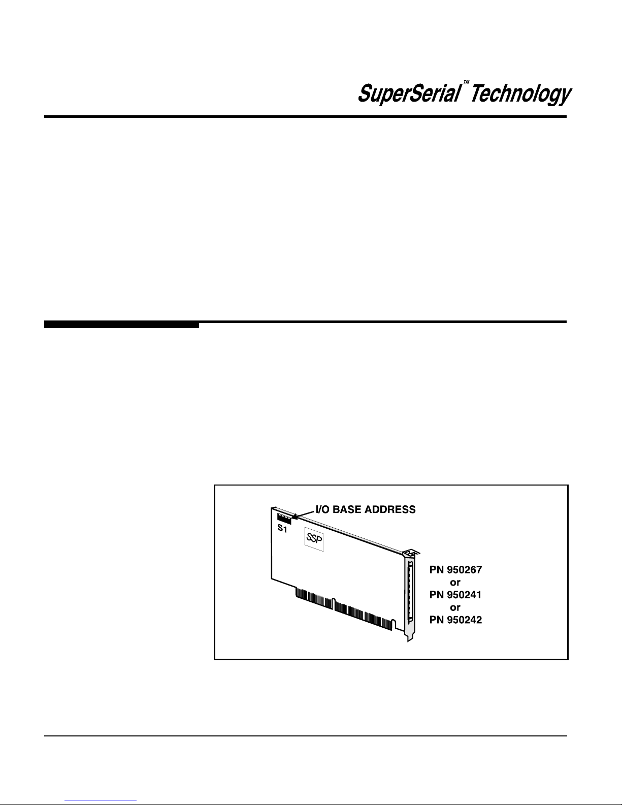
The ISA Megaport SS Board (shown in Figure 2-1) must be assigned a
unique I/O base address. If multiple ISA boards are installed in the
same system, a different address must be assigned to each board. This
procedure should be performed before the board is physically installed.
Figure 2-1. DIP switch location on ISA Megaport SS Board
Page 14
2-2 Equinox Megaport SS Board Series Hardware Manual
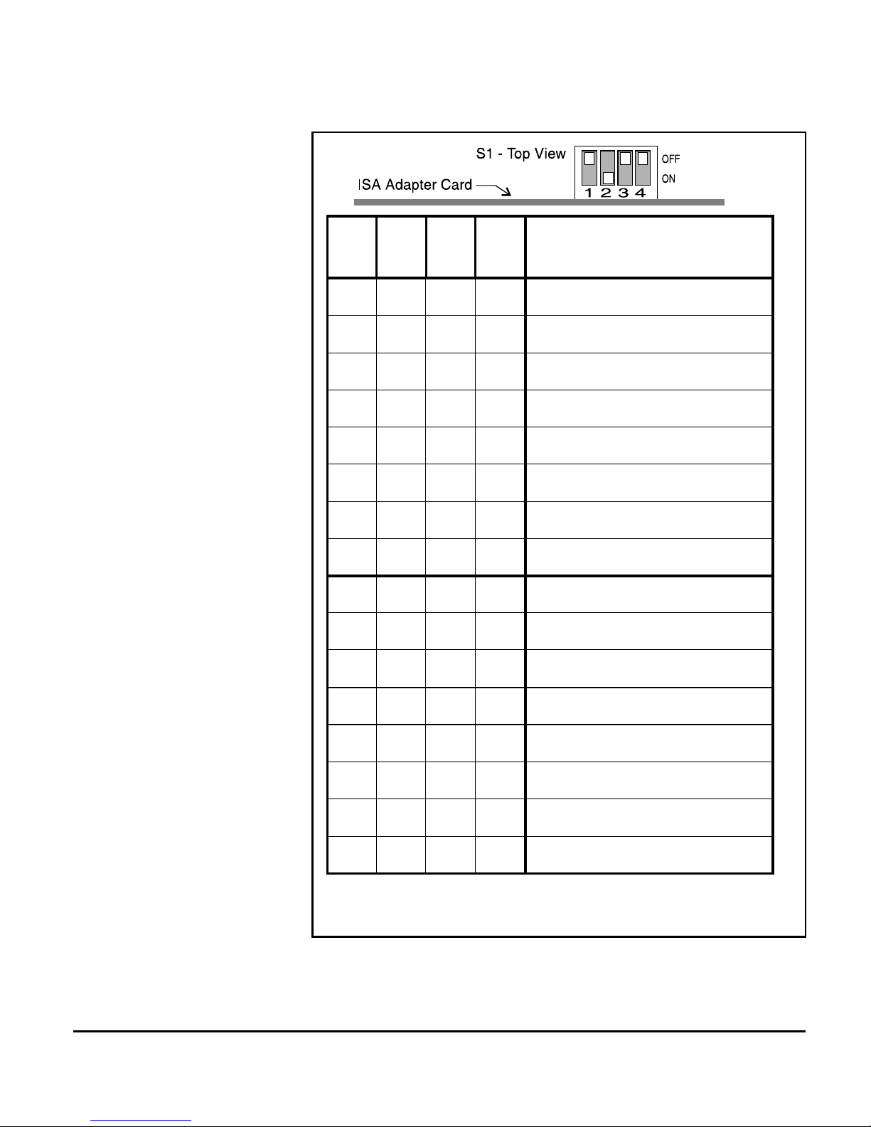
SWITCH S1 IS SHOWN SET FOR I/O BASE ADDRESS 240H
Figure 2-2. ISA I/O Base Address Selections
1 2 3 4 BASE ADDRESS
OFF OFF OFF OFF 200
ON OFF OFF OFF 220
OFF ON OFF OFF 240
ON ON OFF OFF 260
OFF OFF ON OFF 280
ON OFF ON OFF 2A0
OFF ON ON OFF 2C0
ON ON ON OFF 2E0
OFF OFF OFF ON 300
ON OFF OFF ON 320
OFF ON OFF ON 340
ON ON OFF ON 360
OFF OFF ON ON 380
ON OFF ON ON 3A0
OFF ON ON ON 3C0
ON ON ON ON 3E0
Page 15
Installation 2-3
Select a unique I/O base address from the list in Figure 2-2 for the ISA
host controller board. Assign the I/O base address by setting S1 (DIP
switch shown in Figure 2-1) to the selected address.
If you select an address that is invalid, simply shutdown your system
and select another address. It is not necessary to reinstall the software
driver after changing the I/O addresses.
Use the following procedure to install your Megaport SS Board.
Alternatively, you may follow the installation instructions presented in
your host system documentation.
1. Set the host computer system power switch to OFF and
disconnect the power cord.
2. Locate a free expansion slot.
3. Insert and secure the board firmly into the expansion slot.
4. Replace the power cord and turn the host computer
system ON.
You may need to refer to the I/O base address assigned to the board(s)
when installing the driver. Write the selected address for each board
installed in your system in the following table.
I/O Base Address Log
1._________ 2._________ 3._________ 4._________
5._________ 6._________ 7._________ 8._________
Address Log
Board Installation
Page 16

2-4 Equinox Megaport SS Board Series Hardware Manual
System resources for EISA boards are allocated by a menu-driven
program provided by your computer system vendor. Usually there is a
bootable floppy disk called the Configuration Diskette which must be
run whenever a board is added or removed from the system. Each third
party board vendor (such as Equinox) supplies a database of configuration information containing a list of system resources which the board
requires. The configuration (.cfg) files are located in the root directory
of the DOS Diagnostics and Configuration Software For UNIX
Systems diskette. When configuring the system you are asked to put
this diskette into the floppy drive so that the database information can
be copied onto the system disk for later use. Follow the procedures in
your system documentation for the use of this utility. (If you are also
installing an ISA board see the beginning of this chapter for details on
ISA I/O requirements.)
You need not be overly concerned with selecting valid address blocks
because the EISA configuration program is designed to make sure there
are no conflicts over system resources.
EISA Configuration
Diskette
EISA System Setup The EISA Configuration Utility that came with your computer reserves
system resources for each board (subsystem) that is installed. This
resource information is stored in the EISA system CMOS. When your
system boots, the Equinox software driver will read the assigned board
information directly from the CMOS configuration. Following is a
general discussion on using this system utility, you should consult your
host documentation for specific procedures for your system.
Page 17

Installation 2-5
The Micro Channel Setup Utility that came with your computer
reserves system resources for each board (subsystem) that is installed.
This resource information is stored in the Micro Channel system
CMOS. When your system boots, the Equinox software driver will
read the assigned board information directly from the Micro Channel
CMOS configuration. Following is a general discussion on using this
system utility, you should consult your host documentation for specific
procedures for your system.
System resources for Micro Channel adapters are resolved by a menudriven program provided by your computer system vendor. Usually
there is a bootable floppy disk called the Reference Diskette which
must be run whenever a board is added or removed from the system.
Each third party board vendor (such as Equinox) supplies an Option
Diskette containing a database of required system resources. The first
time you turn on the machine with the board installed, an error code
appears and 2 beeps sound after the RAM is counted. This error
message indicates a configuration change was performed and the
machine must be reconfigured to recognize the SSM board(s).
Micro Channel machines require an Adapter Description File (.adf) to
automatically configure each board (adapter) installed. The system
identifies the adaptor by requesting a Programmable Option Select
(POS) ID from adapters installed in the computer. The POS ID for the
boards is 638A. The corresponding adf files (@638A.adf ) for the
SSM Boards containing the configuration information are located in the
root directory of the DOS Diagnostics and Configuration Software For
UNIX Systems diskette. When configuring the system you are asked to
put this Option Diskette into the floppy drive so that the database can
be copied onto the system Diskette for later use. Follow the procedures
in your system documentation for the use of this utility.
Micro Channel
System Setup
Micro Channel
Reference Diskette
Page 18

2-6 Equinox Megaport SS Board Series Hardware Manual
3. Tighten the screws to hold the cable securely to the board.
Equinox wiring accessories convert the 50-pin telco terminating
connector(s) to DB-25 or RJ-11 modular jacks for distribution of ports
to external devices such as terminals, modems and printers. Telco
pinouts and wiring diagrams for the Megaport SS Board accessories are
found in Chapter 3, Cabling Devices To Ports.
Equinox 25-pair extension cables may be used to extend the distance
from the cable attached to the Megaport SS Board to the cabling
accessories. These cables plug into distribution panels, punch blocks,
fan-out cables and modular splitters. Extension cables in various
lengths are available from Equinox.
Installing the Adaptor
Cable
Equinox Wiring
Accessories
Connect the adaptor cable to the Megaport SS Board connector as
follows:
1. Locate the 100-pin female connector on the Megaport SS
Board.
2. Notice that the 100-pin cable connector is keyed such that it
can only attach to the board in one orientation. With the cable
properly oriented, insert the 100-pin male cable connector into
the female Megaport SS Board connector and press firmly.
Page 19
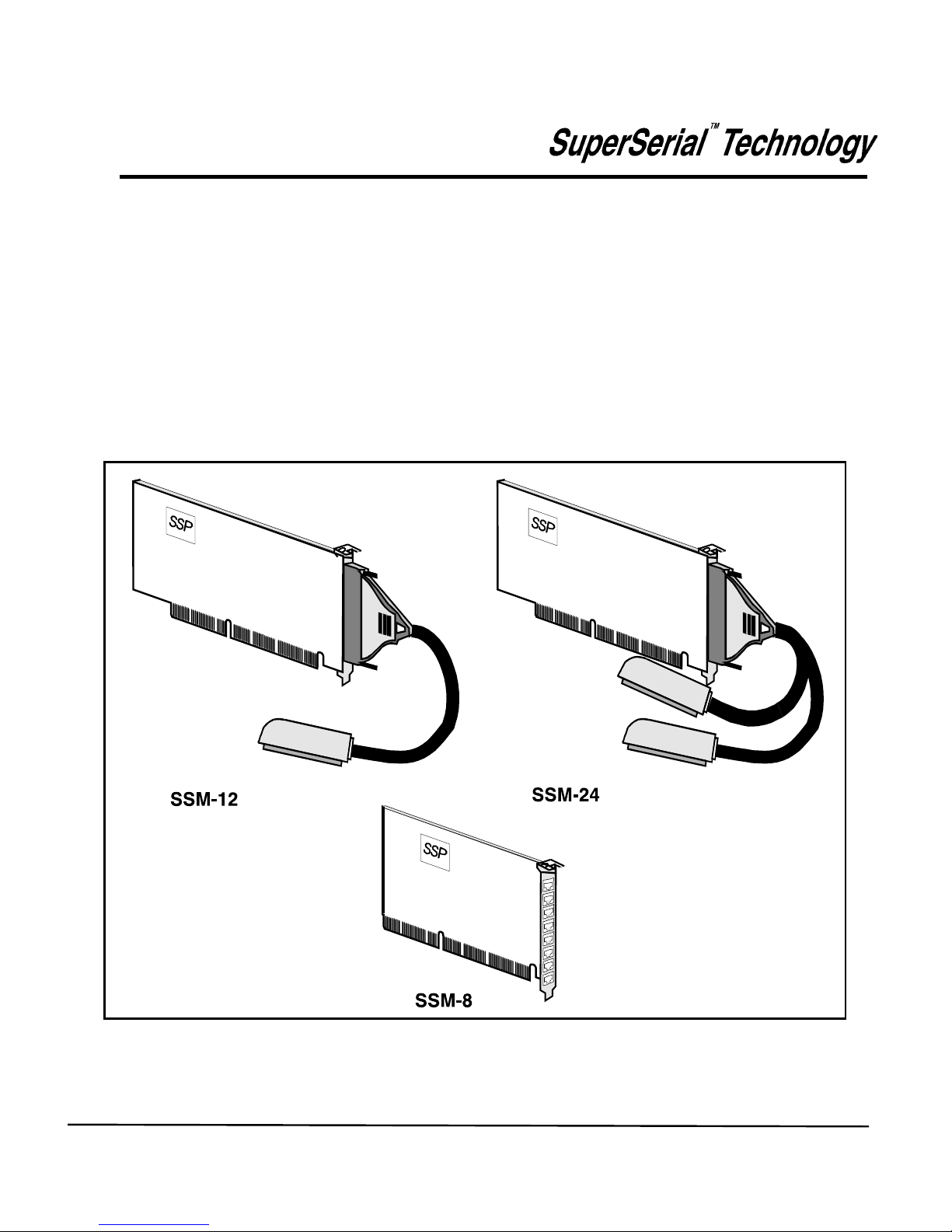
Port to Device Cabling 3-1
3
This chapter describes the options available for cabling devices to ports
connected to Megaport SS Boards (see Figure 3-1). These ports
provide a standard RS-232 interface with modem control signals.
Port to
Device Cabling
Figure 3-1. SSM-8, SSM-12 and SSM-24 Megaport SS Boards
Page 20

3-2 Equinox Megaport SS Board Series Hardware Manual
Port Signal Names
Conversion to RS-232
Signal Names
To assist in wiring the SSM- Megaport board, Equinox sells a
complete set of cabling accessories. See an Equinox Ordering Guide
for more information.
The names of signals on the telco connectors of the Megaport ports
indicate the direction of the signals. They are either inbound (received by the Megaport board) or outbound (transmitted from the
Megaport board).
The following names are used for data signals:
DATA IN indicates data received by the Megaport SS board
from the attached device (inbound).
DATA OUT indicates data transmitted from the Megaport SS
board to the attached device (outbound).
The following names are used for modem control signals:
CNTL IN indicates the control signal received by the
Megaport SS board (inbound).
CNTL OUT indicates the control signal transmitted from the
Megaport SS board (outbound).
Data Signals
EIA Control Signals
The conversion to RS-232 from the Megaport telco pinouts and signal
names (DATA IN, DATA OUT, CNTL IN and CNTL OUT) is accomplished by using Equinox modular adaptors and/or RS-232 distribution
panels. The information below should assist in selecting the correct
modular adaptor for the particular application.
Page 21
Port to Device Cabling 3-3
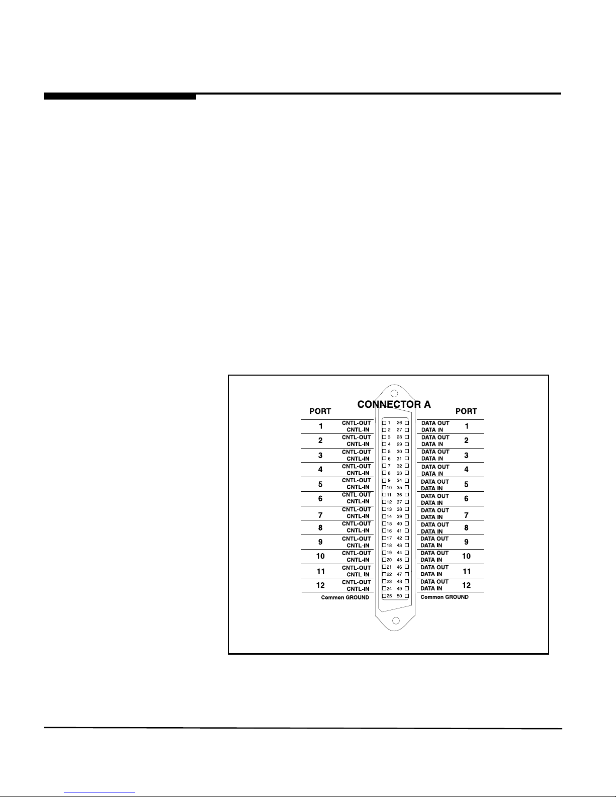
Figure 3-2. SSM-12 Megaport Board telco connector pinouts
SSM-8 Megaport
Board Pinouts
Telco Connector
Pinouts
This part of Chapter 3 lists the cable pinouts of the ports. The physical
ports are mapped by the device driver into UNIX/XENIX tty device
names.
Port one is the upper most port on the back of the SSM-8. See Figure
3-9 for RS232 pinout information.
Figure 3-2 shows the wiring of the telco connector on the SSM-12
Megaport Board. A single cable provides all the signals required for
supporting 12 ports.
SSM-12 Megaport
Board Telco Connector
Pinouts
Page 22
3-4 Equinox Megaport SS Board Series Hardware Manual
SSM-24 Megaport
Board Telco Connector
Pinouts
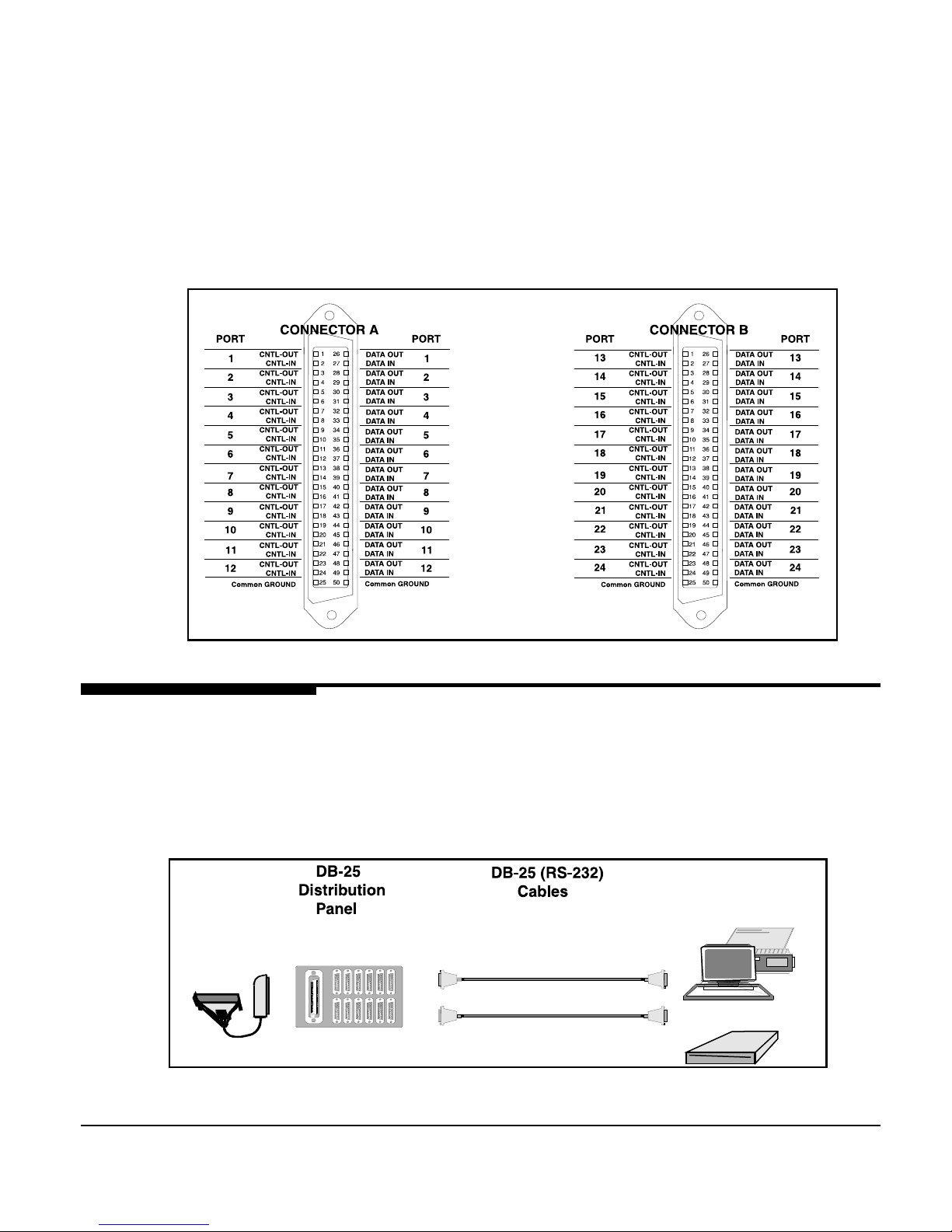
The wiring of the telco connectors on the SSM-24 Megaport Board is
shown in Figure 3-3. Connector A provides ports 1-12 and is identical
to the SSM-12 connector. Connector B provides ports 13-24.
Va rious accessories may be used to connect devices to Megaport SS
ports. The two primary wiring methods are: DB-25 wiring and
modular wiring.
Figure 3-4. DB-25 cable wiring
DB-25 distribution panels are used to convert 50-pin connectors to
DB-25 RS-232 connectors (see Figure 3-4).
DB-25 Wiring
Wiring to Terminal
Devices
Figure 3-3. SSM- 24 Megaport Board telco connector pinouts
Page 23
Port to Device Cabling 3-5
Modular Wiring
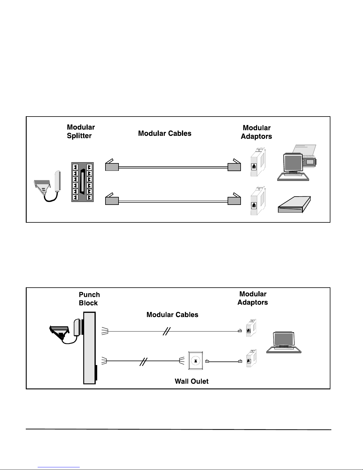
Modular splitters are used with modular adaptors and modular cables
to connect devices to the board (see Figure 3-5).
Modular adaptors and cables are used for attaching devices to the
selected cabling option (see Figures 3-5 and 3-6).
Figure 3-5. Modular cable wiring
Punch blocks may also be used with modular wall outlets and other
modular accessories (see Figure 3-6).
Figure 3-6. Punch block modular cable wiring
Page 24
3-6 Equinox Megaport SS Board Series Hardware Manual
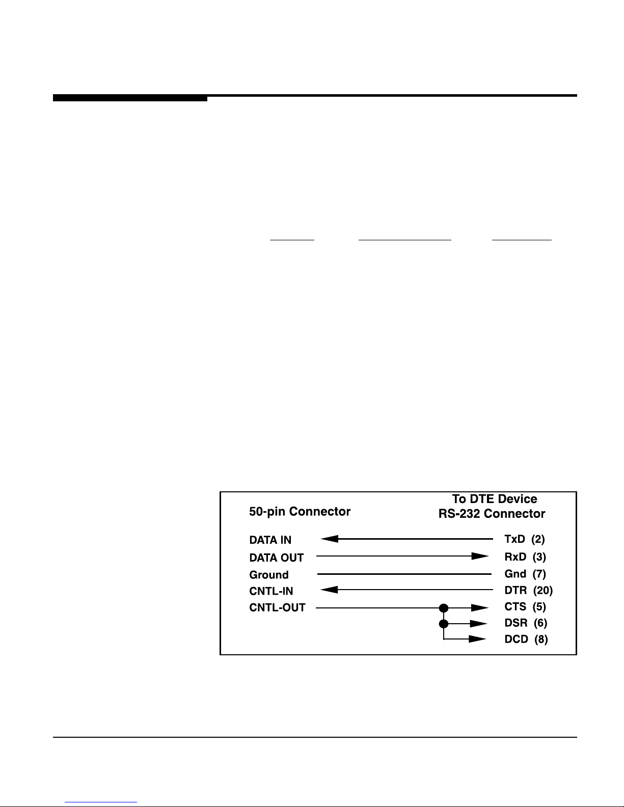
Figure 3-7. Internal wiring for DCE distribution panels
DB-25 Wiring
DB-25 Distribution
Panels
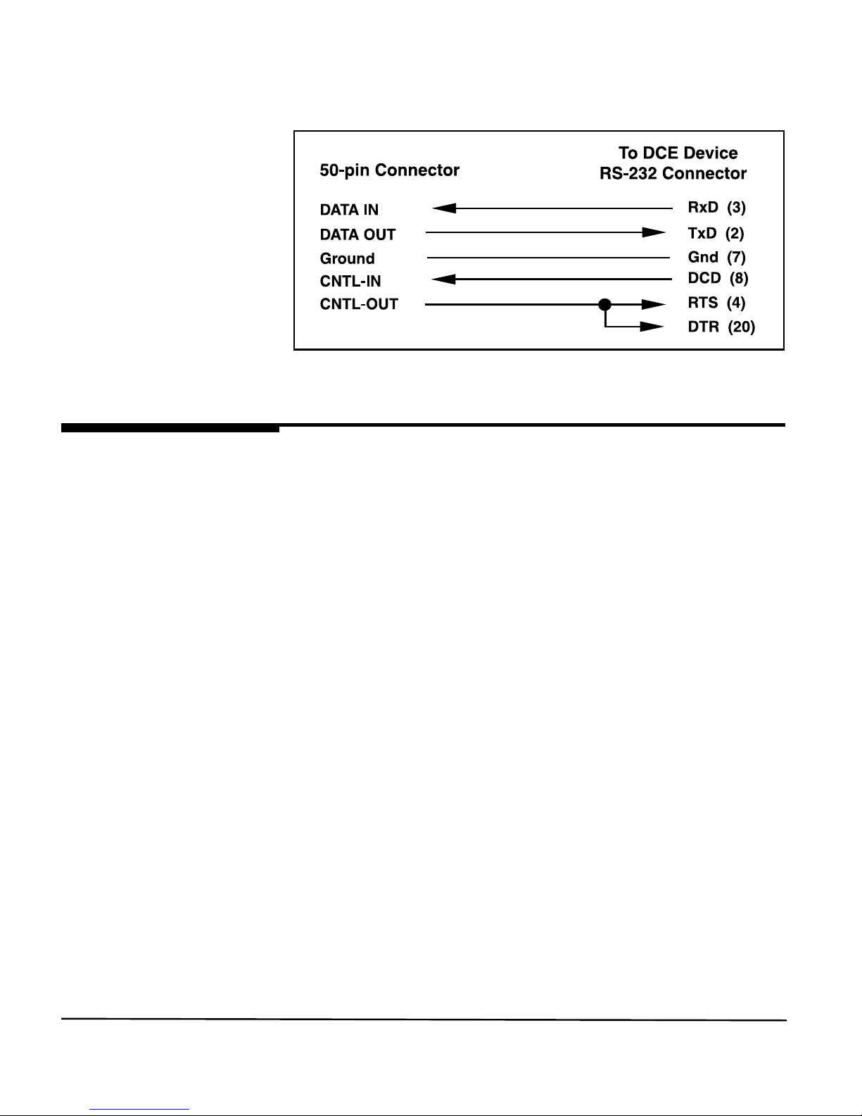
Distribution panels convert 50-pin connectors to twelve DB-25 RS232 connectors (see Figure 3-4). One distribution panel or fan-out
cable is required for 12 devices. Two are required for 24 ports.
The following distribution panels are available from Equinox:
Part No. DB-25 Connector Connect To
990117 12 DCE female terminals and
DTE devices
990121 12 DTE male modems
990122 12 DTE female male DCE
devices
Figures 3-7 and 3-8 illustrate the internal wiring for both DCE and
DTE distribution panels, respectively.
Distribution Panel
Internal Wiring
Page 25
Port to Device Cabling 3-7
Figure 3-8. Internal wiring for DTE distribution panels
Modular Wiring
Modular Splitter Modular splitters are used with modular adaptors and modular cable.
Modular splitters convert the 50-pin connector to a set of 12 modular
jacks. Figure 3-5 illustrates devices connected to the Megaport using
the modular splitter.
● The modular splitter (Equinox part number 210016) converts the
signals on the 50-pin connector to 12 RJ-11 modular jacks. (Two
modular splitters are required to connect 24-devices.) This splitter
should be used to connect to ports only.
● Either 4 or 6-wire modular cable may be used to attach devices to
the splitter. The outer two wires which support control signals are
omitted when using 4-wire cables. Standard modular cables used
for telephones are always reversing (e.g. pin 1 is connected to pin
4, etc.) and are typically 4-wire. If a user supplied modular cable
is used, make sure the cable is reversing (see paragraph heading
Modular Cables).
● Modular adaptors convert modular jacks at the end of modular
cables to DB-25 RS-232 connectors. One adaptor for each device
to be connected is required.
Page 26
3-8 Equinox Megaport SS Board Series Hardware Manual
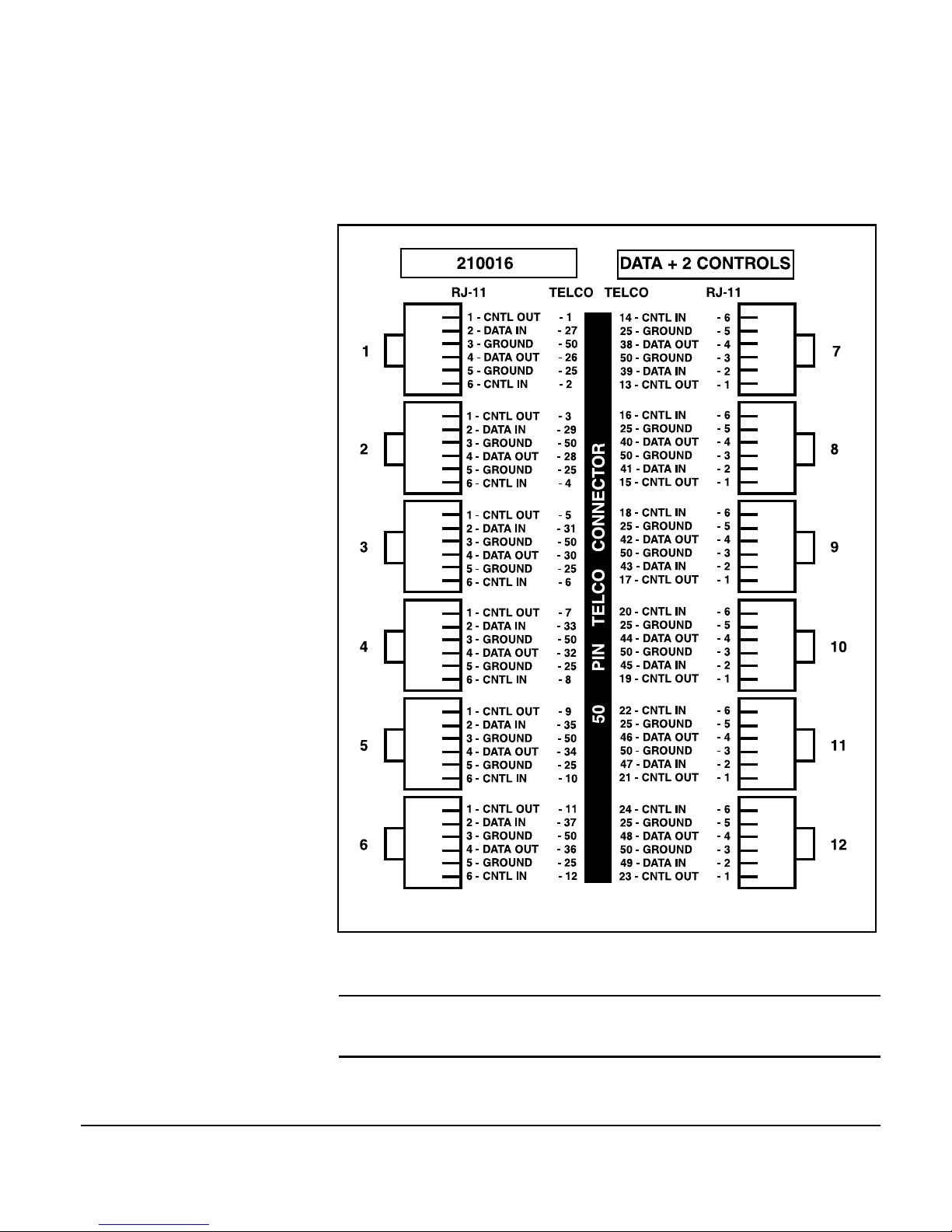
The modular splitter is wired as shown in Figure 3-9. Signal names
shown refer to those present on the telco connector.
Figure 3-9. Modular splitter wiring
SSM-8 ports are wired the same as shown above for ports 1 through 8.
☞
Page 27
Port to Device Cabling 3-9
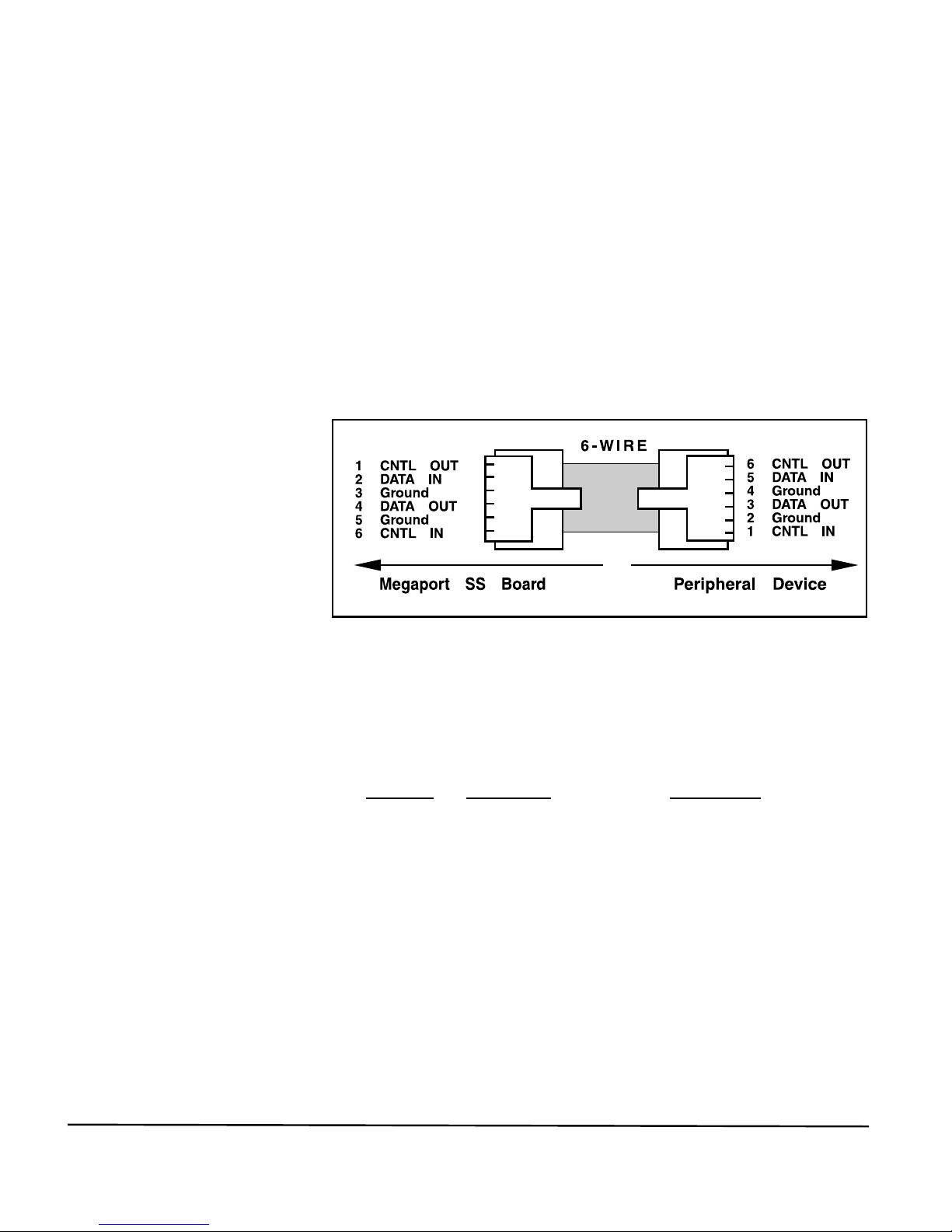
Figure 3-10. Modular cable signals
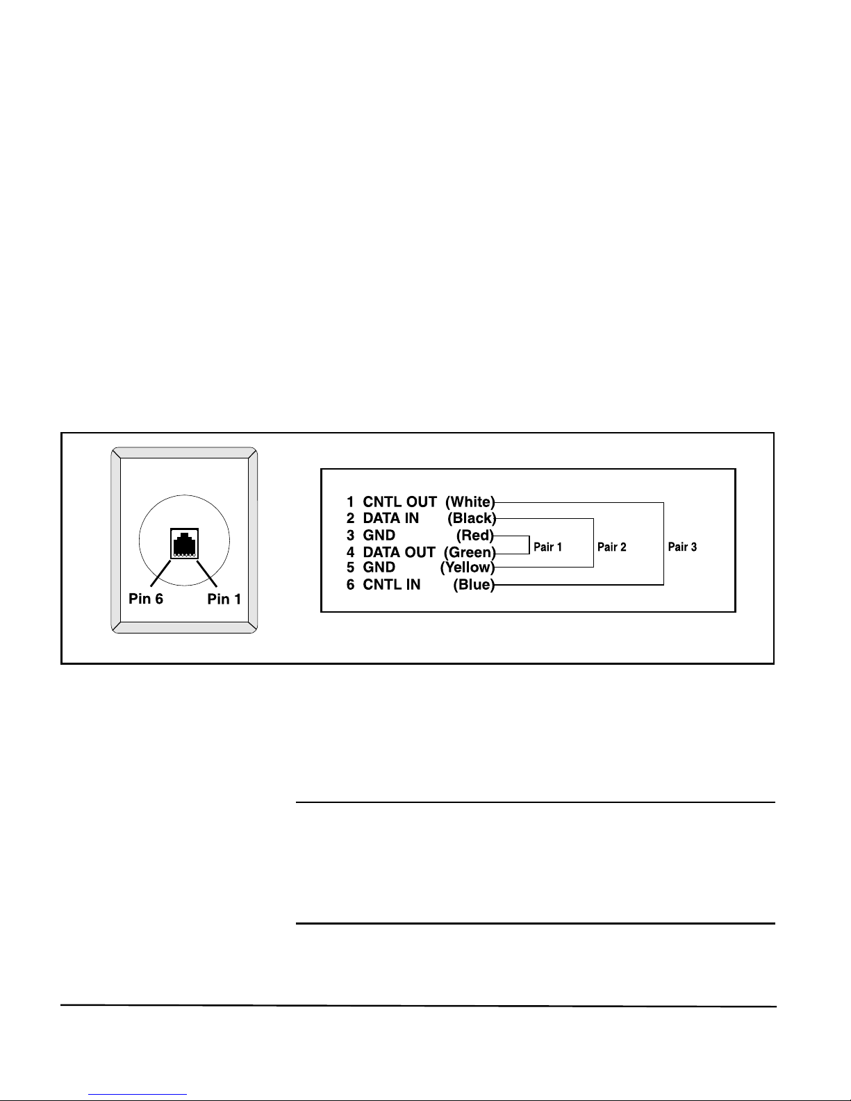
Modular Cables
RJ-11 modular cable is the flat cable used for wiring telephones inside
of buildings. The cable is terminated at each end with a RJ-11
modular plug (connector). This plug is inserted into the modular jack
of an appropriate wiring module. Standard modular cables, available
from Equinox or wiring distributors, are reversing. That is, the pins
are reversed on each end so that pin 1 on one end is connected to pin 6
on the opposite end (pin 2 is connected to pin 5, etc). Figure 3-10
illustrates the signals passed through modular cables when connected
to a port using the Equinox part number 210016 modular splitter.
Modular Adaptors
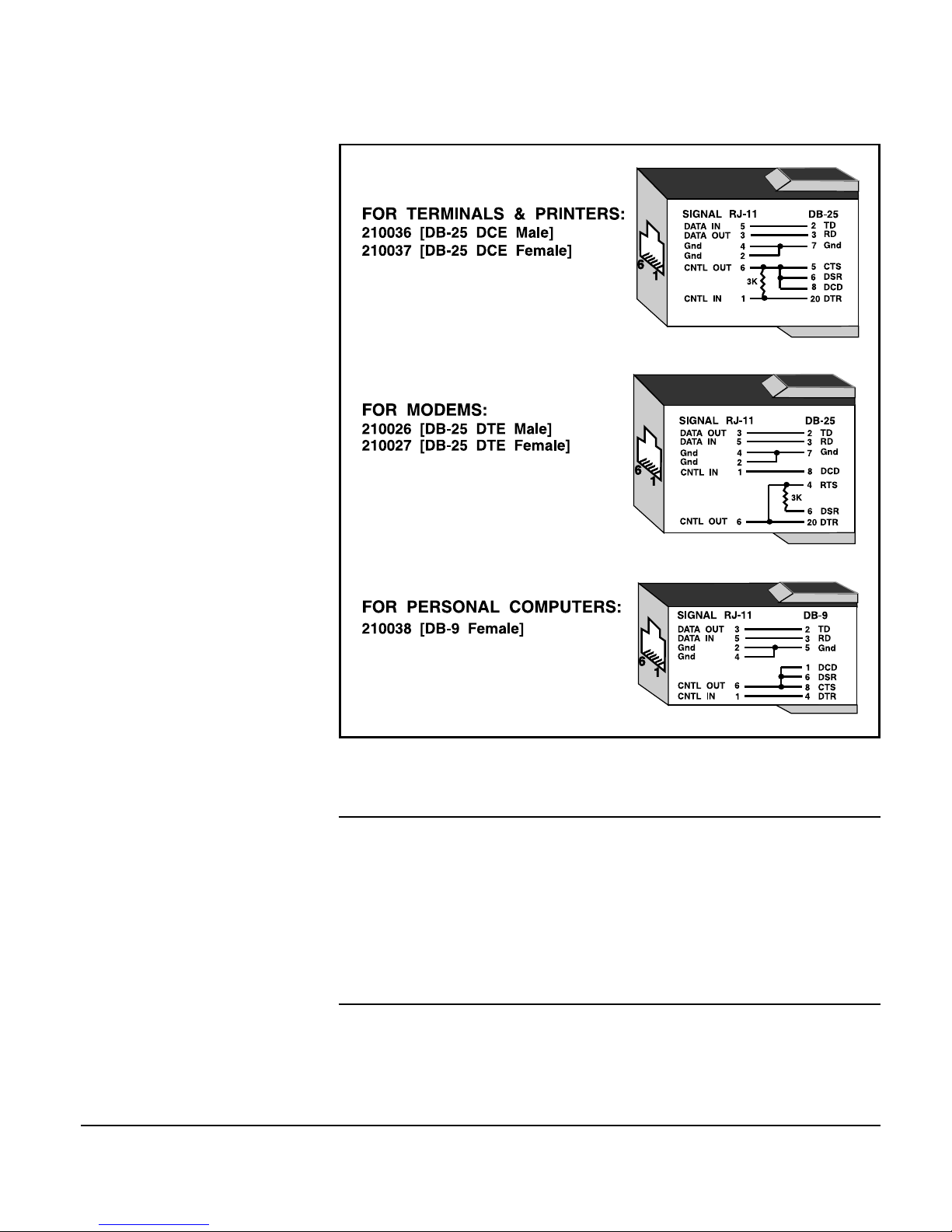
Modular adaptors (see Figure 3-11) convert modular jacks to DB-25
or DB-9 connectors. The following list describes the modular adaptors
available from Equinox. This list may be used to determine the
correct modular wiring accessories required for system installation.
Part No. Connector Connect To
210036 DB-25 DCE male terminals or ports
(female DTE )
210037 DB-25 DCE female terminals, ports, etc.
210026 DB-25 DTE male modems or multiplexer
channels (female DCE )
210027 DB-25 DTE female Male DCE devices
(nonstandard devices)
210038 DB-9 female PC serial port
Page 28
3-10 Equinox Megaport SS Board Series Hardware Manual
Figure 3-11. Modular adaptors
When making modular adaptors, the 3K resistor shown in Figure 3-11
may be eliminated for use with most terminals. The resistor is used to
loop control signals back to the attached device when 4-wire cable is
used and pin 6 is not connected. When using 6-wire cable and there is
a voltage on pin 6, the resistor has no effect and the voltage on pin 6 is
passed through to the attached device.
☞
Page 29
Port to Device Cabling 3-11
Punch Blocks
Figure 3-12. Modular wall outlet wiring
should be wired as shown in Figure 3-12.
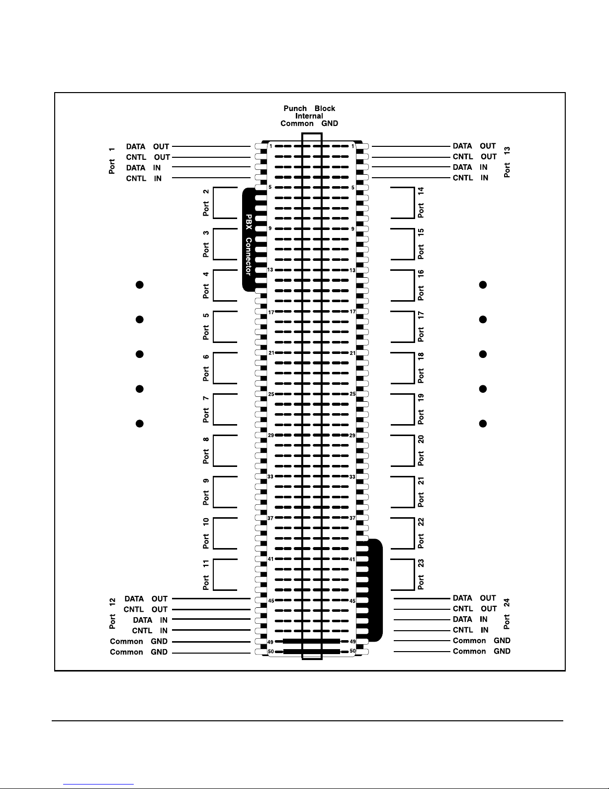
Figure 3-13 shows the pinouts for the Equinox part number 210044
punch block when connected to a Megaport SS board.
The punch block has two 50-pin PBX connectors and connects 24
ports. Also, the punch block has an internal common ground wired to
the center two rows of pins. Any of these pins may be used for
connecting terminal ground to the port.
☞
Punch blocks provide a quick and inexpensive solution to wiring
around buildings. They may be concealed in wiring closets and
individual wires run to each location where a terminal or port is to be
connected. Punch blocks may be used with modular wall outlets and
wiring accessories.
Figure 3-6 illustrates connecting the Megaport SS board to punch
blocks using modular adaptors and modular wall outlets. Wall outlets
Page 30
3-12 Equinox Megaport SS Board Series Hardware Manual
Figure 3-13. Punch block (PN 210044) wiring
PBX Connector
Page 31

Support Procedures A-1
A
Support Procedures
Technical Support
Procedures
Equinox systems has made every effort to ensure that your Megaport
SuperSerial Technology Board is of top quality in all respects. If you
have a problem, please follow these steps:
1. Read the appropriate hardware and software manuals and any
release notes which describe the procedure you are trying to
perform.
2. Check the Equinox Bulletin Board. To access the board, call
(954) 746-0282 with any speed modem using N-8-1 as the
communications parameters.
3. Contact the distributor from whom you purchased the board.
Equinox authorized distributors are fully trained on
SuperSerial Port products and are authorized to handle
technical support, service, returns and warranty claims.
4. If you still need assistance after calling your distributor or other
point of purchase, call Equinox Technical Support at
(954) 746-9000. You can also send problem reports, bug reports
and questions to our fax number: (954) 746-9101 or e-mail
address: [email protected]. Please have the following
information available when you place your call:
Board Type:
Serial Number:
Date of Purchase:
Place of Purchase:
Operating System:
Operating System V ersion:
Device Driver Version:
Computer Make & Model:
Other Boards in Machine:
Description of Problem:
Page 32

A-2 Equinox Megaport SS Board Series Hardware Manual
Manual
Operating System/
Version
Driver Version
Problem
Solution
Documentation
Support Procedures
At Equinox we are always striving to make our product manuals
accurate and easy to read. If you have an improvement to suggest or
find an error in this manual please let us know.
Megaport SS Board Series, Hardware Manual, (560092/B)
What could be added or changed to make the manual better?
Y our Name: Title:
Company: Phone:
Send to: Equinox Systems Inc.
A TTN: Customer Service
One Equinox Way
Sunrise, Florida 33351-6709
Phone: 954-746-9000 Fax: 954-746-9101
Page 33

Equinox Megaport SS Board Series, Hardware Manual Index-1
Symbols
.adf .....................................................................2-5
@638A.ADF...................................................... 2-5
210027 ...............................................................3-9
210036 ...............................................................3-9
210037 ...............................................................3-9
210044 .............................................................3-11
638A .................................................................. 2-5
66-type punch blocks .......................................3-11
990117 ............................................................... 3-6
990121 ...............................................................3-6
990122 ...............................................................3-6
A
Adapter Description File ................................... 2-5
Adaptors
modular .............................3-5, 3-9, 3-10, 3-1 1
making your own ..................................... 3-10
C
Cables
extension ........................................................2-6
modular ................................................. 3-7, 3-9
reversing ........................................................3-9
CNTL IN ........................................................... 3-2
CNTL OUT ....................................................... 3-2
configuration (.cfg) files .................................... 2-4
Control signals ...................................................3-2
CPU ...................................................................1-1
CS modular splitter ................................... 3-7, 3-9
wiring .............................................................3-8
Index
D
DATA IN............................................................ 3-2
DATA OUT........................................................3-2
DB-25 ................................................................ 2-6
DB-25 distribution panels.................................. 3-6
DB-25 wiring
CS ports .........................................................3-4
Distribution panel wiring ...................................3-6
Distribution panels............................................. 3-4
DB-25 ............................................................ 3-6
Driver Diskette .................................................. 1-2
E
EISA ..................................................................1-1
EISA Configuration Diskette............................. 2-4
e-mail ................................................................A-1
Equinox Bulletin Board .................................... A-1
Equinox Technical Support...............................A-1
Extension cables ................................................2-6
I
ISA..................................................................... 1-1
ISA Multiport Board..........................................2-1
L
LAN ...................................................................1-1
M
Megaport 8CS.................................................... 3-1
Megaport 12CS.................................................. 3-1
Megaport SS Boards.......................................... 3-1
Page 34

Index-2 Equinox Megaport SS Board Series, Hardware Manual
memory mapped devices ...................................2-1
Micro Channel ................................................... 1-1
Modem control signals ......................................3-1
Modular adaptors.................. 3-2, 3-5, 3-10, 3-11
making your own .........................................3-10
Modular cables ................................. 3-5, 3-7, 3-9
Modular splitters
CS ..................................................................3-7
Modular wall outlets ............................... 3-5, 3-11
Multiport Boards ............................................... 1-1
O
Off-Load ............................................................ 1-1
Option Diskette.................................................. 2-5
Ordering Guide ..................................................3-2
P
Pinouts
CS modular splitter ........................................3-8
distribution panel ........................................... 3-6
punch block..................................................3-12
POS ID...............................................................2 - 5
Programmable Option Select .............................2-5
Punch blocks.................................................... 3-1 1
wiring ...........................................................3-12
R
Reversing cables ................................................ 3-9
RJ-11..................................................................2-6
RS-232 ...............................................................3-1
conversion to......................................... 3-2, 3-4
S
Software Driver Diskette ................................... 1-2
Splitters
modular
CS .............................................................. 3-7
SSM-12.............................................................. 3-1
SSM-24.............................................................. 3-1
SSM-8................................................................3-1
SST Multiport Boards........................................1-2
T
T echnical Support.............................................A-1
Telco connector ........................................ 2-6, 3-2
U
UNIX ................................................................. 1-1
W
Wall outlets ............................................. 3-5, 3-11
Wiring
CS modular splitter ........................................3-8
distribution panel ........................................... 3-6
punch block..................................................3-12
Wiring closets .................................................. 3-11
 Loading...