

Equinox Systems MEGAPORT 12CS, MEGAPORT 24CS, MEGAPORT 12FM, MEGAPORT 12LD, MEGAPORT 24LD Hardware Reference Manual
...Page 1

Hardware
Reference
Manual
MEGAPORT
Serial I/O Boards
including
MEGAPORT:
MEGAPORT 12CS
MEGAPORT 24CS
MEGAPORT 12FM
MEGAPORT 12LD
MEGAPORT 24LD
MEGAPORT 12LD+12CS
MEGAPORT/2:
MEGAPORT/2 12CS
MEGAPORT/2 24CS
MEGAPORT/2 12FM
MEGAPORT/2 12LD
MEGAPORT/2 24LD
MEGAPORT/2 12LD+12CS
MEGAPORT/RS:
MEGAPORT/RS 12CS
MEGAPORT/RS 24CS
MEGAPORT/RS 12LD
MEGAPORT/RS 24LD
MEGAPORT/RS 12LD+12CS
e
Page 2

ii MEGAPORT Hardware Reference Manual
Copyright Notice
© 1989, 1990, 1991, 1992, 1993 Equinox Systems Inc. All rights reserved.
Reproduction without permission prohibited
.
Trademarks
Equinox is a registered trademark of Equinox Systems, Inc. MEGAPORT is a
trademark of Equinox Systems, Inc. XENIX is a registered trademark of
Microsoft Corp. UNIX is a registered trademark of AT&T.
Disclaimer
Equinox makes no representations or warranties with respect to the contents
hereof and specifically disclaims any implied warranties of merchantability or
fitness for any particular purpose. Information is subject to change without
notice and does not represent a commitment on the part of Equinox Systems Inc.
FCC Notice
NOTE: The equipment has been tested and found to comply with the limits for
Class A digital devices, pursuant to Part 15 of the FCC rules. These limits are
designed to provide reasonable protection against harmful interference when the
equipment is operated in a commercial environment. This equipment generates, uses, and can radiate radio frequency energy and, if not installed and used
in accordance with the instruction manual, may cause harmful interference to
radio communications. Operation of this equipment in a residential area is
likely to cause harmful interference in which case the user will be required to
correct the interference at his own expense.
NOTE: This unit was tested with shielded cables on the peripheral devices.
Shielded cables must be used with the unit to insure compliance.
NOTE: The manufacturer is not responsible for any radio or TV interference
caused by unauthorized modifications to this equipment. Such modifications
could void the user’s authority to operate the equipment.
Document Reference Information
Document Title: MEGAPORT Hardware Reference Manual
Part Number: 560047/B
Date: March, 1993
Control: Equinox Systems Inc., One Equinox Way
Sunrise, FL 33351, 954-746-9000, Fax: 954-746-9101
Page 3
Table of Contents iii
Table of Contents
1 INTRODUCTION 1
Applicability 4
About This Manual 4
Equipment Checklist 5
Software Support 6
References 7
2 INSTALLING MEGAPORT BOARDS 9
The MEGAPORT Board 9
EISA Installations 10
Intermixing MEGAPLEX & MEGAPORT 10
Installing a Single MEGAPORT Board 11
Installing Multiple MEGAPORT Boards 13
PS/2-Type Hardware Configuration 15
RS/6000 Hardware Configuration 17
Installing the Round Cable 18
3 CONNECTING DEVICES TO CS & FM PORTS 19
CS Port Signals 20
Signal Names 20
Conversion to RS-232 Signal Names 20
Telco Connector Pinouts 21
FM Port Signals 24
Signal Names 24
Wiring to Terminal Devices 25
DB-25 Wiring 27
Modular Wiring 28
CS Port Full Modem Control Wiring 36
Special Considerations 38
Wiring Conventions 38
Non-Conventional Wiring 38
Page 4

iv MEGAPORT Hardware Reference Manual
4 CONNECTING DEVICES TO LD PORTS 39
LD Port Signals 41
Signal Names 41
Conversion to RS-232 Signal Names 41
Telco Connector Pinouts 42
Wiring to Terminal Devices 45
LD Cabling Issues 45
LD Cabling Schemes 46
DB-25 Wiring 48
Modular Wiring 49
APPENDIX A DOCUMENT CHANGE REQUEST 55
APPENDIX B TECHNICAL SUPPORT PROCEDURES 57
Index 59
Page 5
Table of Contents v
e
MEGAPORT
MEGAPORT/2
MEGAPORT/RS
Serial I/O Boards
PN 560047/B
Hardware
Reference
Manual
Page 6

Page 7

Introduction 1
CHAPTER 1
INTRODUCTION
The Equinox MEGAPORT, MEGAPORT/2 and MEGAPORT/RS
family of multi-user boards provides the highest performance serial
I/O solution for UNIX, XENIX and AIX applications in ISA, EISA
and Micro Channel bus systems.
Except for the computer bus interface and an additional step in the
hardware configuration process, MEGAPORT/2 and MEGAPORT/RS
products are identical to their MEGAPORT counterparts. In this
manual the term MEGAPORT refers to all nineteen products:
ISA and EISA Bus Products:
● MEGAPORT 8CS: an 8-port board with standard RS-232
interface and modem control signals on all ports. This
board is not addressed in this manual; refer to the
MEGAPORT 8CS Hardware Reference Manual, Equinox
part number 560044.
● MEGAPORT 12CS: a 12-port board with standard RS-232
interface and modem control signals on all ports.
● MEGAPORT 24CS: a 24-port board with standard RS-232
interface and modem control signals on all ports.
● MEGAPORT 12FM: a 12-port board with standard RS-232
interface and full modem control signals on all ports.
● MEGAPORT 12LD: a 12-port board with on-board line
drivers for long distance applications which do not require
modem control signals.
● MEGAPORT 24LD: a 24-port board with on-board line
drivers for long distance applications which do not require
modem control signals.
● MEGAPORT 12LD+12CS: a 24-port board. The first 12
ports use on-board line drivers for long distance
applications which do not require modem control signals.
The second twelve ports provide the standard RS-232
interface with modem control signals on all ports.
Page 8

2 MEGAPORT Hardware Reference Manual
Micro Channel Products for IBM PS/2 and NCR
3000 Systems:
● MEGAPORT/2 12CS: a 12-port board with standard RS-
232 interface and modem control signals on all ports.
● MEGAPORT/2 24CS: a 24-port board with standard RS-
232 interface and modem control signals on all ports.
● MEGAPORT/2 12FM: a 12-port board with standard RS-
232 interface and full modem control signals on all ports.
● MEGAPORT/2 12LD: a 12-port board with on-board line
drivers for long distance applications which do not require
modem control signals.
● MEGAPORT/2 24LD: a 24-port board with on-board line
drivers for long distance applications which do not require
modem control signals.
● MEGAPORT/2 12LD+12CS: a 24-port board. The first 12
ports use on-board line drivers for long distance
applications which do not require modem control signals.
The second twelve ports provide the standard RS-232
interface with modem control signals on all ports.
Micro Channel Products for IBM RISC System/6000:
● MEGAPORT/RS 12CS: a 12-port board with standard
RS-232 interface and modem control signals on all ports.
● MEGAPORT/RS 24CS: a 24-port board with standard
RS-232 interface and modem control signals on all ports.
● MEGAPORT/RS 12LD: a 12-port board with on-board
line drivers for long distance applications which do not
require modem control signals.
● MEGAPORT/RS 24LD: a 24-port board with on-board
line drivers for long distance applications which do not
require modem control signals.
● MEGAPORT/RS 12LD+12CS: a 24-port board. The first
12 ports use on-board line drivers for long distance
applications which do not require modem control signals.
The second twelve ports provide the standard RS-232
interface with modem control signals on all ports.
Page 9

Introduction 3
All of these boards differ only in the bus interface, the number of
ports provided on each and in the methods used to connect the
boards to terminals, printers and modems.
CS
MEGAPORT models with CS in their name provide the traditional RS-232 interface, including two modem control signals,
which may be used for either DTR/DCD modem supervision or
RTS/CTS hardware flow control. The MEGAPORT 12CS and
24CS models come with a cable terminating in a 50-pin telco
connector which can be attached to a variety of splitters and
distribution panels for device connection. The MEGAPORT
8CS provides this interface at 8 modular jacks located directly
on the board’s mounting bracket.
FM
MEGAPORT models designated FM provide RS-232 interface
signals with full modem control and may be used for modem,
terminal and/or printer hardware flow control. The
MEGAPORT 12FM models come with a 12-port RJ-45 (ten pin
connector jacks) splitter for device connection and a 100conductor cable for connecting the board to the splitter.
LD
MEGAPORT models with LD in their name include a custom
interface which is compatible with RS-232, RS-422 and RS-423
devices. These boards are designed for applications requiring
long cable runs, beyond the limits of the standard RS-232
interface and operate with standard RS-232 devices at 38.4
Kbps to distances of up to 1000 feet.
This distance may be further extended to 3000 feet using an
Equinox LDA-232 line driver at the terminal end. LD boards
do not provide modem control signals and are designed for use
with terminals, printers and other non-modem devices.
Page 10

4 MEGAPORT Hardware Reference Manual
Applicability
This manual is applicable to the following Equinox products:
● MEGAPORT 12CS
● MEGAPORT 24CS
● MEGAPORT 12FM
● MEGAPORT 12LD
● MEGAPORT 24LD
● MEGAPORT 12LD+12CS
● MEGAPORT/2
● MEGAPORT/2 24CS
● MEGAPORT/2 12FM
● MEGAPORT/2 12LD
● MEGAPORT/2 24LD
● MEGAPORT/2 12LD+12CS
● MEGAPORT/RS 12CS
● MEGAPORT/RS 24CS
● MEGAPORT/RS 12LD
● MEGAPORT/RS 24LD
● MEGAPORT/RS 12LD+12CS
About This Manual
This manual is a complete technical reference to the hardware
installation and operation of all members of the MEGAPORT family
of high-performance multi-user boards, with the exception of the
MEGAPORT 8CS. It should be used in conjunction with one of the
MEGAPORT device drivers discussed below.
There is a considerable similarity in the installation and operation of
all MEGAPORT products. Throughout this manual, the term
MEGAPORT is used and applies to all members of the family.
Specific product names, such as MEGAPORT 12CS and
MEGAPORT/2 24LD are used to refer to issues which are specific to
that board.
This manual is organized as follows:
Chapter 1 - Introduction
Introduces the members of the MEGAPORT family and lists
the hardware and software provided with each MEGAPORT
board.
Chapter 2 - Installing MEGAPORT Hardware
Covers the system installation of MEGAPORT, MEGAPORT/2
and MEGAPORT/RS boards.
Page 11

Introduction 5
Chapter 3 - Connecting Devices to CS and FM Ports
Chapter 3 describes the procedures used to connect devices to
MEGAPORT CS boards (12CS, 24CS and the second 12 ports
on the 12LD+12CS) and MEGAPORT 12FM boards. Included
are wiring diagrams for assistance in building adaptors and
cables.
Chapter 4 - Connecting Devices to LD Ports
This chapter describes the procedures used to connect devices
to MEGAPORT LD boards (12LD, 24LD and the first 12 ports
on the 12LD+12CS). Included are wiring diagrams for assistance in building adaptors and cables.
Equipment Checklist
A MEGAPORT package contains:
● MEGAPORT* Board
Installs in any 80286-, 80386- or 80486-based computer.
● 1" Interconnect cable (MEGAPORT only)
Used to connect multiple MEGAPORT boards together.
● EISA Jumper (MEGAPORT only)
For EISA bus computers.
● UNIX/XENIX Device Driver Kit
Provides the software and manual required for installing
MEGAPORT boards in systems running the UNIX System
V 3.2/386 operating system, the 286 or 386 SCO XENIX
operating system and compatible variants.
● UNIX STREAMS Device Driver Kit
Provides the software and manual required for installing
MEGAPORT boards in systems running the UNIX System
V Release 4 STREAMS operating system and compatible
variants.
● AIX-2 Device Driver Kit (MEGAPORT/2 only)
Provides the software and manual required for
installing MEGAPORT/2 boards in systems running IBM
AIX Version 2.
● AIX-3 Device Driver Kit (MEGAPORT/RS only)
Provides the software and manual required for installing
MEGAPORT/RS boards in systems running IBM AIX
Version 3.
Page 12

6 MEGAPORT Hardware Reference Manual
Different device driver kits with different part numbers are
provided with MEGAPORT, MEGAPORT/2 and
MEGAPORT/RS (slight differences in the installation process
necessitate this for ease of installation). With MEGAPORT/2
boards a PS/2 Option Diskette is also included.
*MEGAPORT 12FM and MEGAPORT/2 12FM products
include a 12-port RJ-45 Splitter and a 100-conductor
interconnecting cable.
Software Support
MEGAPORT products are supported under various operating systems by different software device drivers supplied by Equinox and
other vendors. At the time of this writing, the following device
driver kits (including diskettes and manuals) are available for
MEGAPORT:
● UNIX System V 3.2/386 operating system, SCO XENIX 286 or
386 operating system and compatible variants. Included with
MEGAPORT and MEGAPORT/2 boards. For MEGAPORT:
Equinox part number 650078 (both 5.25" and 3.5" diskettes).
For MEGAPORT/2: Equinox part number 650053 (3.5" diskettes).
● UNIX System V Release 4 STREAMS operating system and
compatible variants. Included with MEGAPORT and
MEGAPORT/2 boards. For MEGAPORT: Equinox part number
650074 (both 5.25" and 3.5" diskettes). For MEGAPORT/2:
Equinox part number 650089 (3.5" diskettes).
● IBM AIX Version 2.x operating system. Included with
MEGAPORT/2 boards. Equinox part number 650079 (3.5"
diskettes).
● IBM AIX Version 3.x operating system. Included with
MEGAPORT/RS boards. Equinox part number 650081 (3.5"
diskettes).
● QNX and THEOS operating systems. Available in North
America from Florida Datamation, 1-800-642-5938. Available
elsewhere from Equinox.
For other supported operating systems not listed, consult your
authorized Equinox sales representative.
Page 13

Introduction 7
References
In addition to this manual and the appropriate Software Reference
Manual as provided in a device driver kit, readers may be interested
in these publications:
For combined installation of MEGAPORT and MEGAPLEX:
MEGAPLEX Hardware Reference Manual, part number
560050.
For LD board installation:
Technical Note #1, MEGAPORT LD: Exploring Long Distance
Connections to Terminals & Printers. Part number 302024. A
copy is shipped with all LD boards.
Page 14

8 MEGAPORT Hardware Reference Manual
Page 15
Installing MEGAPORT Boards 9
Chapter 2
Installing MEGAPORT Boards
This chapter describes how to install MEGAPORT, MEGAPORT/2
and MEGAPORT/RS boards into a computer system. The following
topics are covered:
● The MEGAPORT Board
● EISA Installations
● Intermixing MEGAPLEX and MEGAPORT Boards
● Installing a Single MEGAPORT Board
● Installing Multiple MEGAPORT Boards
● PS/2 Type Hardware Configuration
● RS/6000 Hardware Configuration
● Installing the Round Cable
The MEGAPORT Board
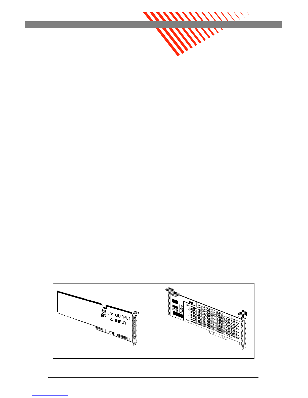
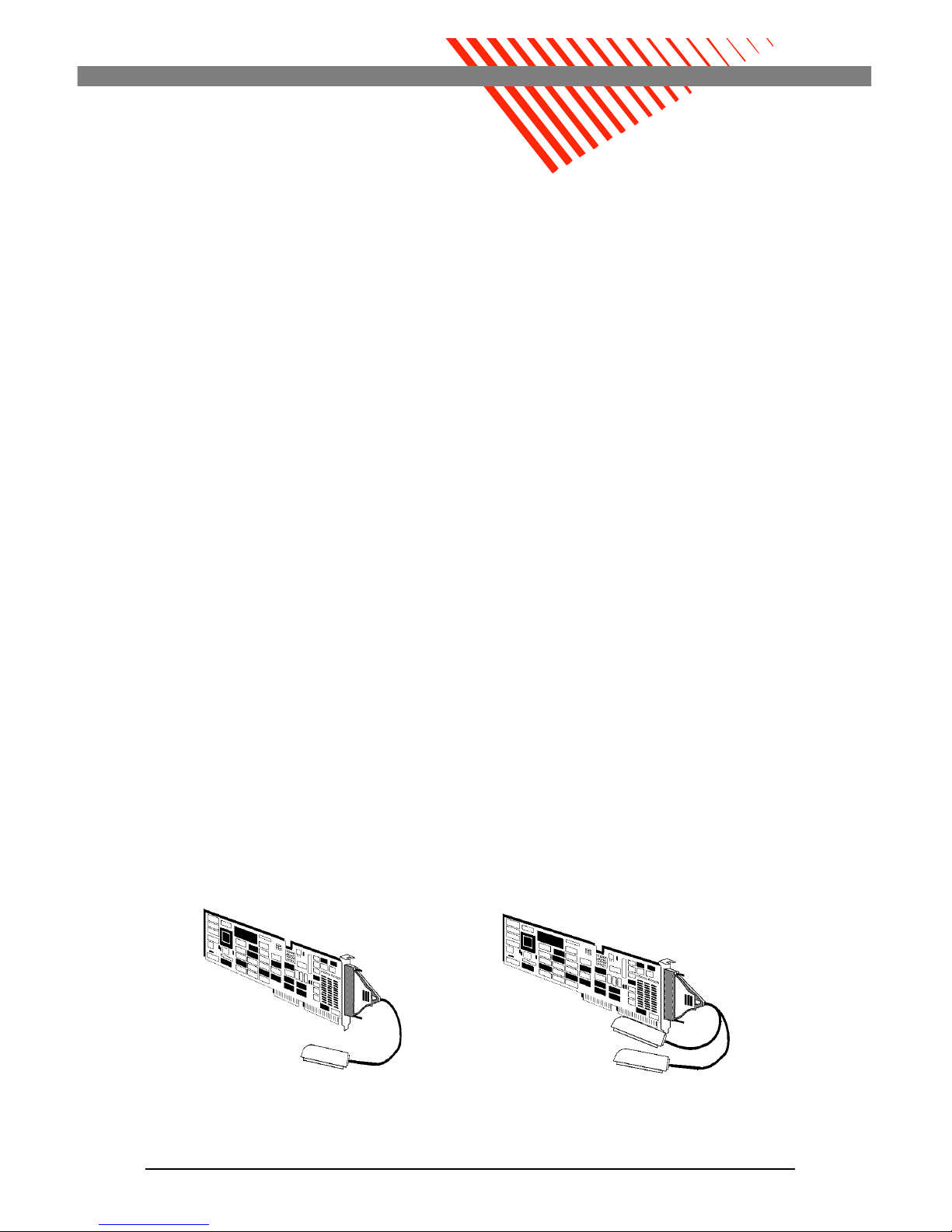
Figure 2-1 is an illustration of the MEGAPORT boards. No hardware
configuration is required on the board. However, make careful note of
the J2 and J3 connector locations. J2 is the input connector and J3 is
the output connector. These connectors are used when more than one
MEGAPORT board is installed. Interconnections between boards are
not required when installing multiple MEGAPORT/2 or
MEGAPORT/RS boards.
Figure 2-1. MEGAPORT, MEGAPORT/2 and MEGAPORT/RS boards
MEGAPORT/2 and
MEGAPORT/RS
MEGAPORT
Page 16
10 Equinox MEGAPORT Hardware Reference Manual
EISA Installations
When installing a MEGAPORT board in an EISA system, a jumper
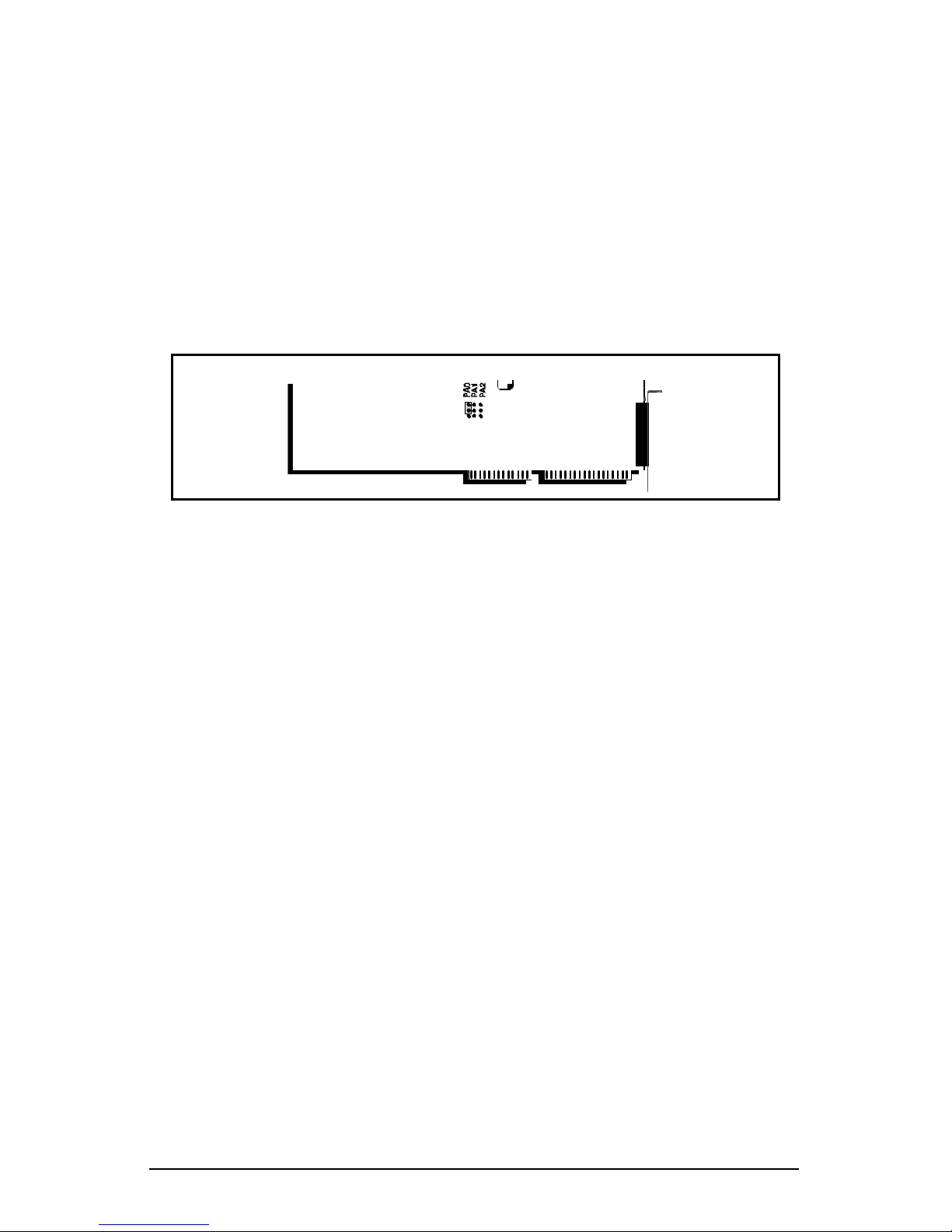
must be installed to permit the configuration scheme to work properly. This jumper causes the MEGAPORT board to occupy I/O addresses 0x340 and 0x341. These addresses should not be used by
another device.
Install the jumper across the left top-most two pins denoted by "PA0"
on the printed circuit board (see Figure 2-2). This figure shows only
PA0 installed to select addresses 0x340 and 0x341. Install the jumper
in the same location on all MEGAPORT boards.
Intermixing MEGAPLEX & MEGAPORT
MEGAPORT boards may be intermixed with other Equinox products
including the MEGAPORT 8CS and MEGAPLEX. MEGAPORT/2
boards may be intermixed with MEGAPLEX/2. MEGAPORT/RS
boards may be intermixed with MEGAPLEX/RS.
The MEGAPORT 8CS is in all respects equivalent to a 24CS board
except it has RJ-11 modular jacks on the mounting bracket. It
installs in a system the same as a MEGAPORT board except for
device wiring. Refer to the MEGAPORT 8CS Hardware Reference
Manual (part number 560044) for more information.
The MEGAPLEX serial I/O subsystem is functionally equivalent to
multiple MEGAPORT boards and may also be intermixed in a computer. There are some minor considerations in the physical installation. Refer to the MEGAPLEX Hardware Reference Manual (part
number 560050) for more information .
Figure 2-2. Installing the EISA configuration jumper
Page 17
Installing MEGAPORT Boards 11
Installing a Single MEGAPORT Board
The first MEGAPORT board installed should be placed in the first
available computer slot. On a desktop chassis IBM AT, this is the
first empty slot closest to the power supply. In a tower chassis, it is
the topmost slot. By installing the MEGAPORT board in the first
empty slot (closest to the power supply), the next MEGAPORT board
installed is close enough to connect up with the 1" interconnect cable.
MEGAPORT/2 and MEGAPORT/RS boards do not require the interconnect cable, so any slot may be used. The first board is referred to
as MEGAPORT Board #1.
The following steps describe how to install the MEGAPORT board in
a personal computer:
● Set the system unit power switch to OFF.
● Disconnect the power cord and all other cables from the
back of the system unit.
● Locate and remove the cover mounting screws and slide the
cover off the unit (or lift the cover up depending upon the
type of chassis).
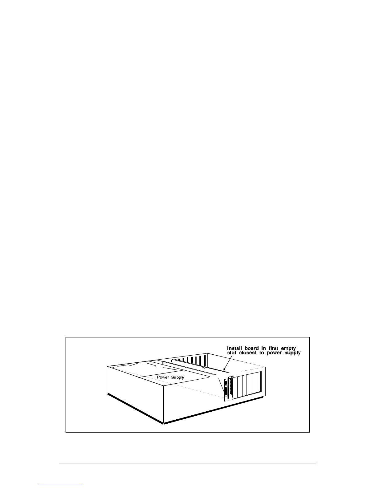
● Locate the first free expansion slot closest to the power
supply (see Figure 2-3). For MEGAPORT/2 and
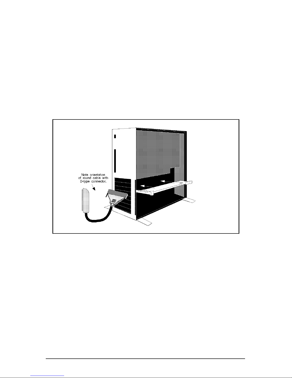
MEGAPORT/RS, use any slot (see Figure 2-4). Remove the
expansion slot cover by first removing the screw which
holds the cover in place and then lifting off the slot cover
completely.
● Insert the board firmly into the computer’s expansion slot.
Make sure the gold striped end of the board is seated
properly in the expansion slot groove and the bracket of the
board is in the groove which previously held the slot cover.
Figure 2-3. Installing MEGAPORT board in desktop chassis
Page 18
12 Equinox MEGAPORT Hardware Reference Manual
● After making sure that the top of the board’s bracket is
aligned with the hole on the top of the expansion slot,
replace the screw which previously held the expansion slot
cover. Tighten the screw so it holds the board firmly in
place.
● If more than one MEGAPORT board is to be installed, refer
to paragraph heading Installing Multiple MEGAPORT
Boards.
● Leave the cover of the computer off (or open) until it is
verified that the board is working. If a loose connection or a
bad slot is suspect, it may be necessary to change the
board's slot location.
Figure 2-4. Installing MEGAPORT in a tower chassis
Page 19

Installing MEGAPORT Boards 13
Installing Multiple MEGAPORT Boards
MEGAPORT boards may be installed and intermixed with other
Equinox products (such as, MEGAPORT 8CS and MEGAPLEX
boards) in a computer system. Likewise, MEGAPORT/2 boards may
be intermixed with MEGAPLEX/2 and MEGAPORT/RS boards may
be intermixed with MEGAPLEX/RS in their respective computer
system chassis.
For multiple MEGAPORT/2 and MEGAPORT/RS, simply install the
additional boards in empty slots in the computer. The interconnect
cable is not required for Micro Channel MEGAPORT products.
Keep the following in mind when installing additional MEGAPORT
boards:
● MEGAPORT board #1 is usually the board which is in-
stalled in the slot closest to the power supply. When facing
the front of the computer, subsequent MEGAPORT boards
are installed to the left of previously installed MEGAPORT
boards (next to the non-component side of the installed
board).
● Refer to Figure 2-1 to locate the J2 and J3 connectors.
● Be sure MEGAPORT board #1 is installed according to the
directions outlined in the previous paragraphs.
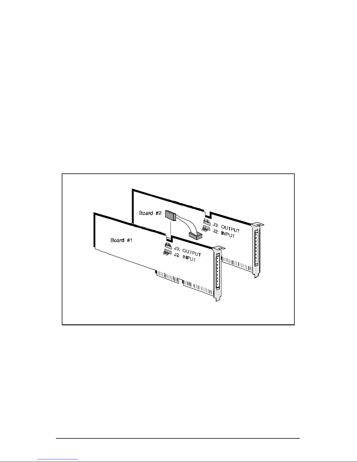
To install additional MEGAPORT boards, perform the following steps
(refer to Figure 2-5):
1. Locate the J2 connector on the board to be installed. This is
located just below the J3 connector. Plug the short interconnect cable into the J2 connector.
2. Locate the free expansion slot located to the left (facing the
front of a desktop chassis computer) or below (for tower
chassis) of the previously installed MEGAPORT board.
Remove the expansion slot cover by first removing the screw
which holds the cover in place. Then lift off the slot cover
completely.
3. Insert the board firmly in the computer’s expansion slot. Be
sure the gold striped end of the board is seated properly in
the slot’s groove and the bracket of the board is in the
groove which previously held the slot cover.
Page 20
14 Equinox MEGAPORT Hardware Reference Manual
4. After making sure that the top of the board’s bracket is
aligned with the hole on the top of the expansion slot,
replace the screw which previously held the expansion slot
cover. Tighten the screw firmly.
5. Connect the interconnect cable on the newly installed board
to the J3 connector on the previously installed board located
to right of the new board.
6. If more than one additional MEGAPORT board is being
installed, repeat steps 1 through 5 for each board.
Note: If the computer has trouble finding the second MEGAPORT
board, suspect a faulty connection with the MEGAPORT 1" interconnect cable. Remove the interconnect cable and reinstall it making
sure none of the pins are bent and all the pins are enclosed by the
interconnect cable.
Figure 2-5. Interconnecting multiple MEGAPORT boards
Page 21

Installing MEGAPORT Boards 15
PS/2-Type Hardware Configuration
MEGAPORT/2 only.
This section applies to the IBM PS/2, the NCR 3000 Series and other
similar Micro Channel Architecture computers. The process described
is essentially the same for each, although some terminology may vary.
After installing the MEGAPORT/2 board, the computer must be
configured. The first time the machine is turned on with the
MEGAPORT/2 installed, an error code of 165 appears on the screen
and 2 beeps are sounded after the RAM is counted. This error
message indicates that the configuration has been changed and the
machine must be reconfigured to recognize the MEGAPORT/2.
Micro Channel machines require an Adapter Description File (ADF)
to automatically configure each peripheral device (adapter) installed.
The system identifies the adaptor by requesting a Programmable
Option Select (POS) ID from adapters installed in the computer. The
POS ID for the MEGAPORT/2 is 6384. The corresponding ADF file
(@6384.ADF) for the MEGAPORT/2 containing the configuration
information for the board is provided on the MEGAPORT/2 Option
Diskette. This file must be copied to a backup of the Reference Diskette
supplied with the computer. The steps for coping the file to the
Reference Diskette backup disk are presented below:
Page 22

16 Equinox MEGAPORT Hardware Reference Manual
1. After the 165 error message, the machine appears to hang.
Place the Reference Diskette in drive A: and press F1. The
screen clears and the banner screen appears. Press Enter to
continue. The following message displays:
Use Automatic Configuration (Y/N)? N
2. Answer no to the automatic configuration question. The
main menu displays:
Main Menu
1. Learn about the computer.
2. Backup the Reference Diskette.
3. Set Configuration.
4. Set features.
5. Copy an option diskette.
6. Test the computer.
Because the MEGAPORT/2 installation modifies the Reference Diskette, a backup of the diskette should be made. A
blank 1.44 MB diskette that is not write protected is required. Select option #2 and follow the instructions. This
step may be skipped if a backup copy is currently being
used.
After completing the backup, store the original Reference
Diskette in a safe place. Continue using the backup.
3. Reboot the system using the backup reference diskette and
select option 5, Copy an option diskette, from the
main menu.
When asked, insert the new Option Diskette into drive A:
and the @6384.ADF file is copied into RAM. Then when
asked, insert the Reference Diskette into drive A and the
@6384.ADF file is appended to the Reference Diskette.
4. After copy is finished and the system returns to the main
menu, the configuration can be set. Select option 3, Set
configuration, from the main menu.
The set configuration menu appears. From this menu,
select option 5, Run automatic configuration.
Set Configuration
1. View configuration.
2. Change configuration.
3. Backup configuration.
4. Restore configuration.
5. Run automatic configuration
Page 23

Installing MEGAPORT Boards 17
5. After running the automatic configuration, the system
CMOS now contains the configuration of all the adapters
including the MEGAPORT/2. At this point, backup the new
configuration by selecting option 3, Backup configura-
tion, from the set configuration menu.
6. The new configuration is copied onto the Backup Reference
diskette. After the backup is complete, remove the Backup
Reference diskette and store it and the original Reference
Disk in a safe place. Exit the POS configuration utilities
and reboot the system from the hard disk. The system
should boot normally and not display the 165 error message.
The system is now ready to have the device driver installed
as described in the appropriate Software Reference Manual.
RS/6000 Hardware Configuration
MEGAPORT/RS only.
After installing MEGAPORT/RS board, the board must be configured
using the IBM SMIT facility. Refer to the AIX-3 Software Reference
Manual, Equinox part number 560049.
Page 24

18 Equinox MEGAPORT Hardware Reference Manual
Installing the Round Cable
Each MEGAPORT package includes a round cable which plugs into
the 100-pin female connector on the MEGAPORT board.
MEGAPORT 12-port boards use a single round cable providing one
standard telco 50-pin telco connector. MEGAPORT 24-port boards
use a double round cable providing two telco connectors.
Equinox wiring accessories convert the telco connectors to DB-25 or
RJ-11 modular jacks for distribution of ports to external devices such
as terminals, modems and printers. The pinouts of the telco
connector vary based on whether the board is a CS, FM or LD type.
Telco pinouts and wiring diagrams for the various CS and LD type
accessories are found in Chapters 3 and 4, Connecting Devices To CS
& FM Ports and Connecting Devices To LD Ports, respectively.
NOTE: The FM board connector pinouts are proprietary to
Equinox and are not furnished. However, the RS-232 signals
for the RJ-45 (10-pin) modular splitter (device connection)
pinouts are identified in Chapter 3.
Follow these steps to connect the cable to the MEGAPORT board:
● Locate the 100-pin female connector on the back of the
MEGAPORT board.
● Notice that the 100-pin cable connector is keyed such that it
can only attach to the board in one orientation. With the
cable properly oriented, insert the 100-pin male cable
connector into the female MEGAPORT board connector and
press firmly. Tighten the screws to hold the cable securely
to the board.
Equinox 25-pair extension cables may be used to extend the distance
from the cable attached to the MEGAPORT board to the cabling
accessories. These cables plug into distribution panels, punch blocks,
fan-out cables and modular splitters. Extension cables in various
lengths are available from Equinox.
Page 25
Connecting Devices to CS and FM Ports 19
Chapter 3
Connecting Devices To CS & FM Ports
This chapter applies equally to MEGAPORT, MEGAPORT/2 and
MEGAPORT/RS and explains the cabling options which may be used
to connect devices to:
● the MEGAPORT 12CS board;
● the MEGAPORT 24CS board;
● the MEGAPORT 12FM board; and
● the second group of twelve ports (i.e. ports numbered 13
through 24) on the MEGAPORT 12LD+12CS board. (The
second group of twelve ports on the MEGAPORT
12LD+12CS board are identical to the corresponding ports
on the 24CS board.)
These ports are all of the CS or FM type and provide a standard RS232 interface with modem or full modem control signals.
NOTE: The information in this chapter should not be used to
connect devices to MEGAPORT 12LD, MEGAPORT 24LD boards or
to connect devices to the first group of twelve ports on the
MEGAPORT 12LD+12CS boards. For information on connecting to
these ports please refer to Chapter 4, Connecting to LD Ports or to
Equinox Technical Note #1, MEGAPORT LD, part number 302024.
To assist in wiring the MEGAPORT board, Equinox sells a complete
set of cabling accessories. See an Equinox Ordering Guide for more
information.
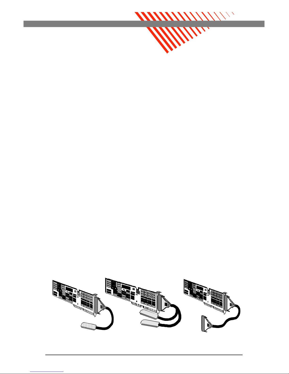
12CS 24CS (or 12LD+12CS) 12FM
Page 26

20 Equinox MEGAPORT Hardware Reference Manual
CS Port Signals
Signal Names
The names of signals on the telco connectors of the MEGAPORT
ports indicate the direction of the signals. They are either inbound
(received by MEGAPORT) or outbound (transmitted from MEGAPORT).
Data Signals
The following names are used for data signals:
DATA IN indicates data received by the MEGAPORT board
from the attached device (inbound).
DATA OUT indicates data transmitted from the MEGAPORT board to the attached device (outbound).
EIA Control Signals
The following names are used for modem control signals:
CNTL IN indicates the control signal received by the
MEGAPORT board (inbound).
CNTL OUT indicates the control signal transmitted from
the MEGAPORT board (outbound).
The conversion to RS-232 from the MEGAPORT telco pinouts and
signal names (DATA IN, DATA OUT, CNTL IN and CNTL OUT) is
accomplished by using Equinox modular adaptors and/or RS-232
distribution panels. The information below should assist in selecting
the correct modular adaptor for the particular application.
Conversion to RS-232 Signal Names
The conversion to RS-232 from the CS telco connector pinouts and
MEGAPORT signal names (DATA IN, DATA OUT, CNTL IN, and
CNTL OUT) is accomplished with one of the Equinox cabling
accessories.
These accessories and wiring techniques are discussed under the
paragraph heading Wiring to Terminal Devices.
Page 27
Connecting Devices to CS and FM Ports 21
Telco Connector Pinouts
This part of Chapter 3 lists the cable pinouts of the CS ports. The
physical ports are mapped by the device driver into UNIX/XENIX
tty device names.
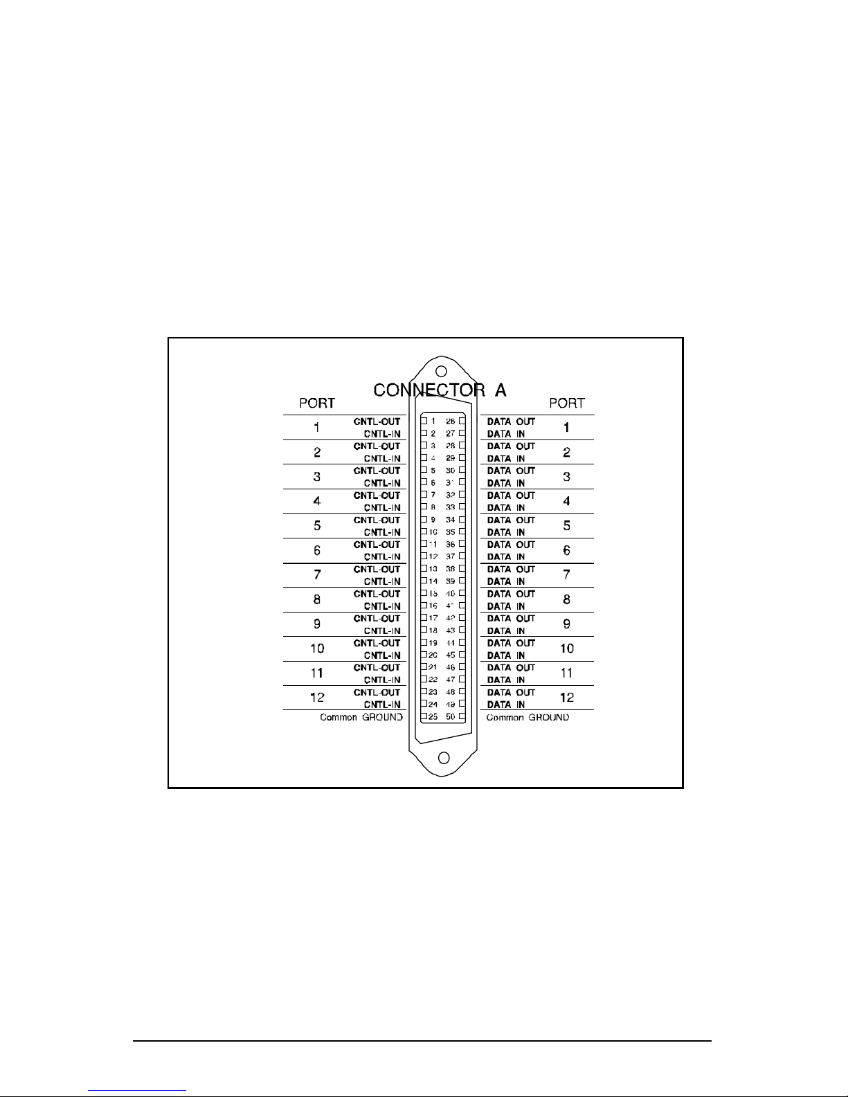
MEGAPORT 12CS Board Telco Connector Pinouts
Figure 3-1 shows the wiring of the telco connector on the MEGAPORT 12CS board. A single cable provides all the signals required
for supporting 12 ports.
Figure 3-1. MEGAPORT 12CS telco connector pinouts
Page 28
22 Equinox MEGAPORT Hardware Reference Manual
MEGAPORT 24CS Board Telco Connector Pinouts
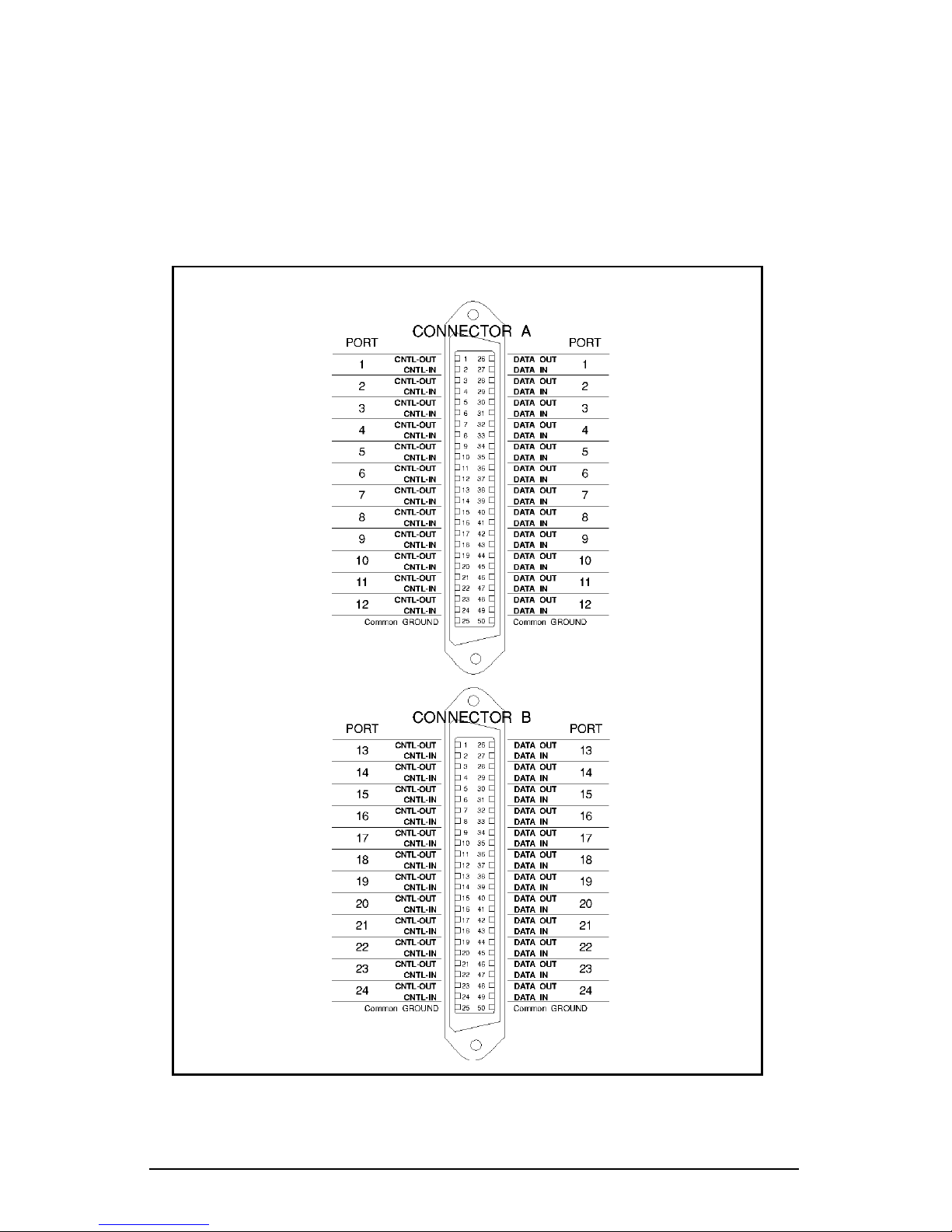
The wiring of the telco connectors on the MEGAPORT 24CS board is
shown in Figure 3-2. Connector A provides CS ports 1-12 and is
identical to the MEGAPORT 12CS connector. Connector B provides
CS ports 13-24.
Figure 3-2. MEGAPORT 24CS telco connector pinouts
Page 29
Connecting Devices to CS and FM Ports 23
MEGAPORT 12LD+12CS Board Telco Connector Pinouts
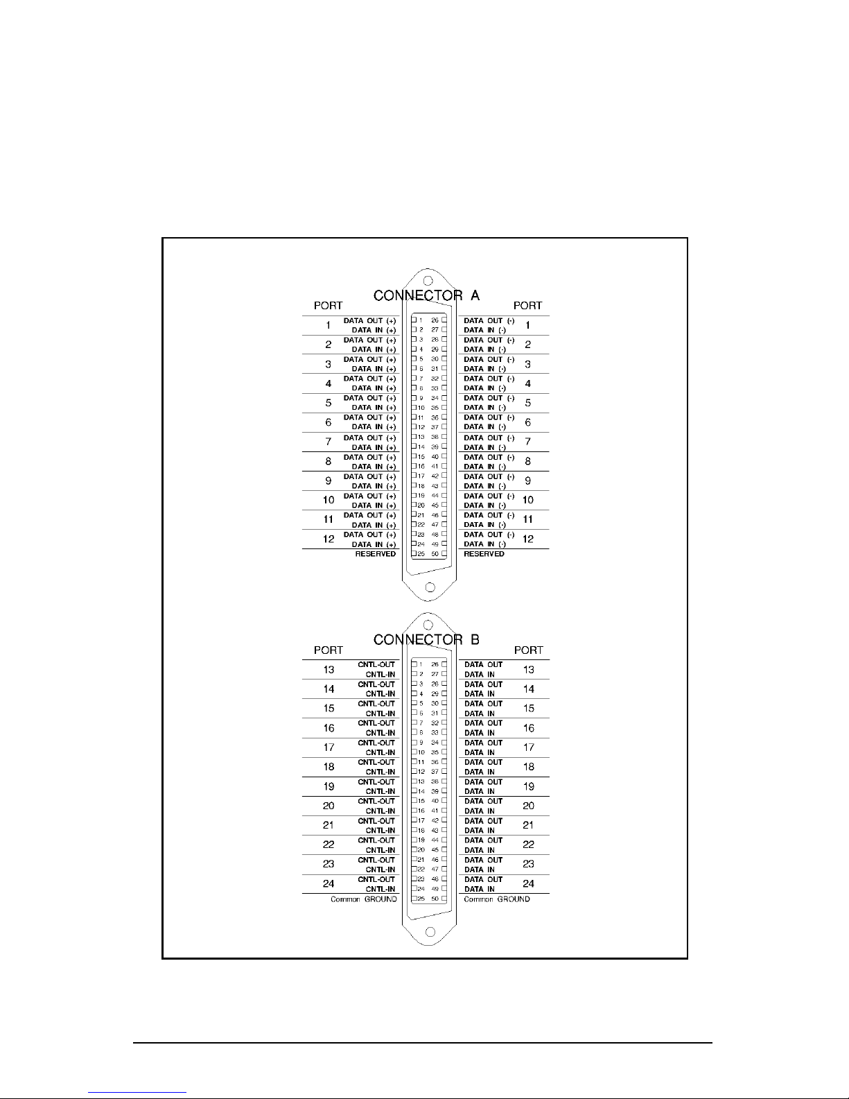
The wiring of the telco connectors of the MEGAPORT 12LD+12CS
board is shown on Figure 3-3. Connector A provides LD ports 1-12
and is identical to the MEGAPORT 12LD connector (see Chapter 4).
Connector B provides CS ports 13-24 and is identical to Connector B
on the MEGAPORT 24CS.
Figure 3-3. MEGAPORT 12LD+12CS telco connector pinouts
Page 30
24 Equinox MEGAPORT Hardware Reference Manual
FM Port Signals
Signal Names
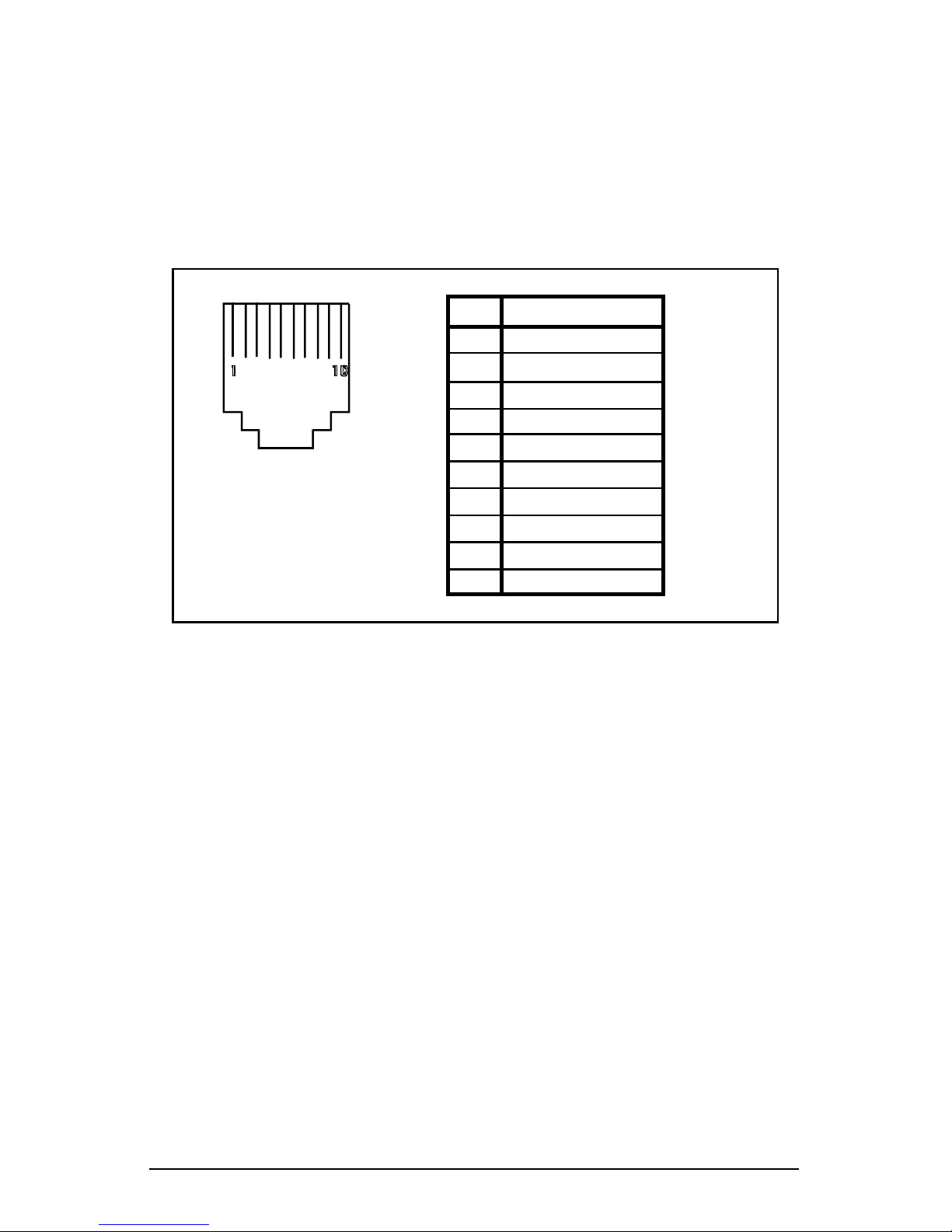
The FM port signals (RS-232 compatible) between the 12 FM Splitter
and the connected devices are identified in Figure 3-4.
All twelve RJ-45 jacks on the 12 FM Splitter are identical in pinout.
1
Pin
2
3
4
5
6
7
8
10
9
Signal
RJ-45
Figure 3-4. 12 FM Splitter RJ-45 jack pinouts.
Ground
Receive Data
Transmit Data
Ground
Carrier Detect
Clear To Send
Data Terminal Ready
Request To Send
Reserved
Data Set Ready
Page 31
Connecting Devices to CS and FM Ports 25
Wiring to Terminal Devices
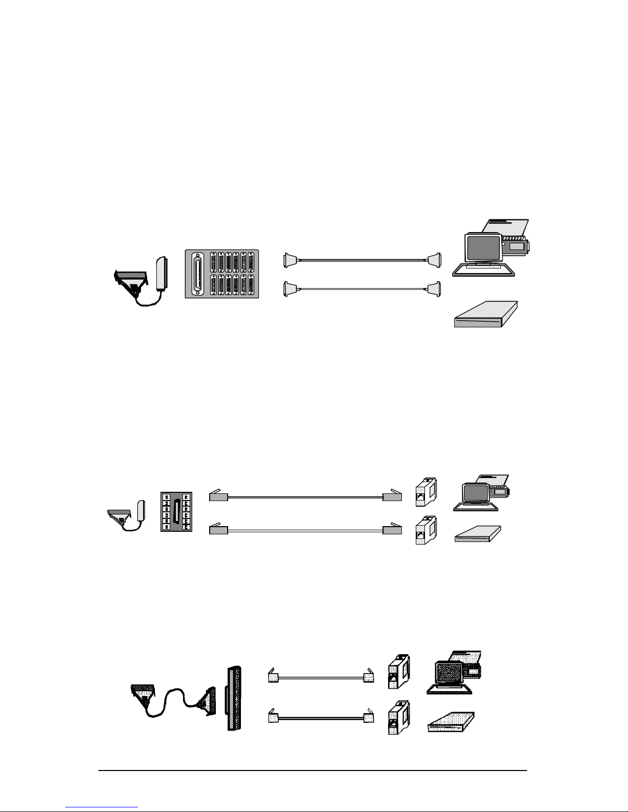
Various accessories may be used to connect devices to MEGAPORT
CS or FM ports, using the two primary wiring methods: DB-25 or
modular wiring. They include:
For DB-25 Wiring:
● DB-25 distribution panels are used to convert 50-pin
connectors to DB-25 RS-232 connectors.
For Modular Wiring:
● Modular splitters are used with modular adaptors and
modular cables to connect devices to the board.
● Modular adaptors and cables are used for attaching
devices to the selected cabling option.
● 12FM modular splitters are used with modular adaptors
and modular cables to connect devices to the MEGAPORT
12FM boards.
DB-25
Distribution Panel
DB-25 (RS-232)
Cables
Modular
Cable
12FM Modular
Splitter
Modular
Adaptors
Modular
Splitter
Modular
Cable
Modular
Adaptors
Page 32
26 Equinox MEGAPORT Hardware Reference Manual
● Punch blocks may also be used with modular wall outlets
and other modular accessories.
Page 33
Connecting Devices to CS and FM Ports 27
DB-25 Wiring
DB-25 Distribution Panels
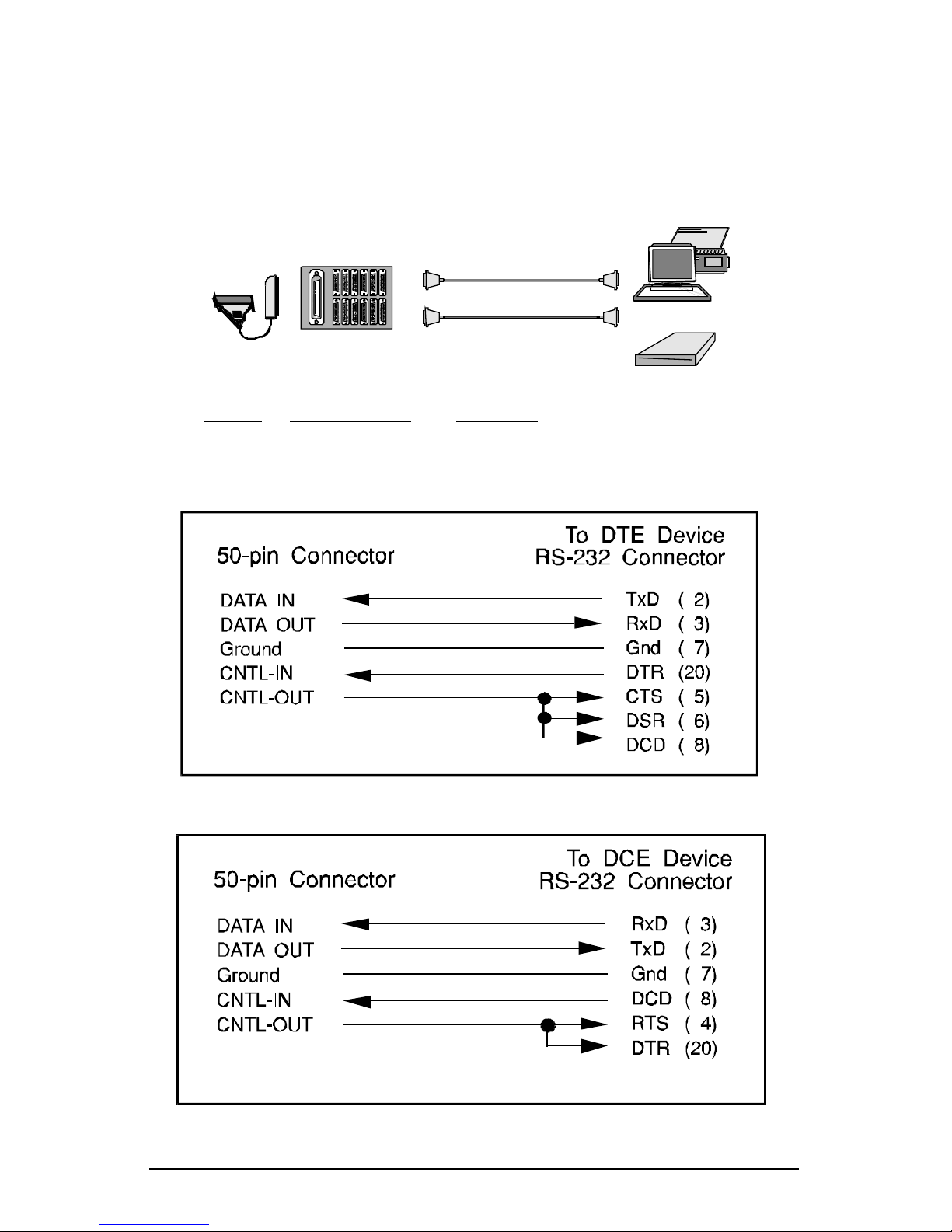
Distribution panels convert 50-pin connectors to twelve DB-25 RS232 connectors. One distribution panel or fan-out cable is required
for 12 devices. Two are required for 24 ports.
The following distribution panels are available from Equinox:
Part No. DB-25 Connector Connect To
990117 12 DCE female terminals and DTE devices
990121 12 DTE male modems
990122 12 DTE female male DCE devices
Figure 3-5. Internal wiring for DCE distribution panels
Figure 3-6. Internal wiring for DTE distribution panels
Page 34
28 Equinox MEGAPORT Hardware Reference Manual
Modular Wiring
CS Modular Splitter
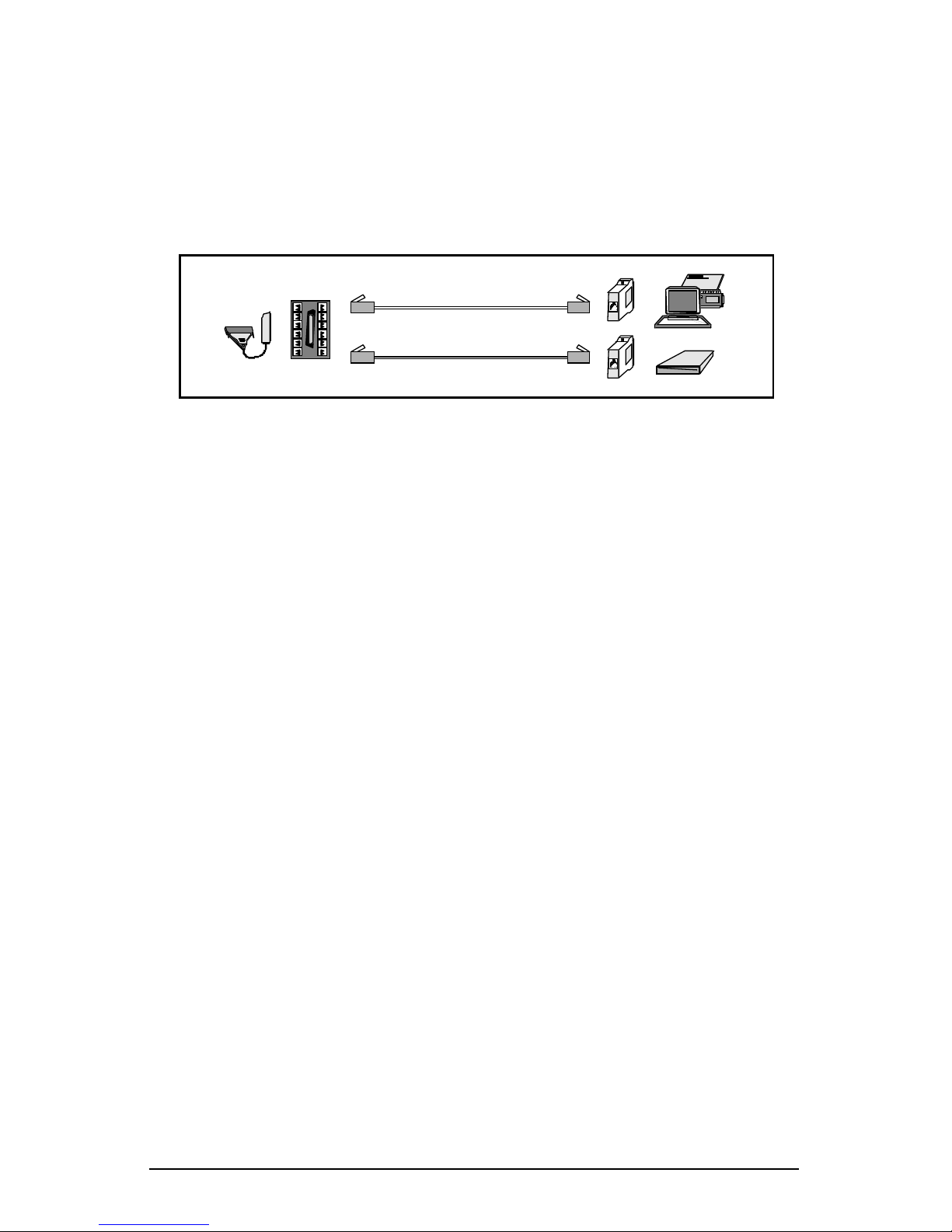
Modular splitters are used with modular adaptors and modular
cable. Modular splitters convert the 50-pin connector to a set of 12
modular jacks. Figure 3-7 illustrates devices connected to the
MEGAPORT using the modular splitter.
● The CS modular splitter (Equinox part number 210016)
converts the signals on the 50-pin connector to 12 RJ-11
modular jacks. (Two modular splitters are required to
connect 24 devices.) This splitter should be used to connect
to CS ports only. An LD version of the modular splitter
(Equinox part number 210117) is available for connecting
devices to LD ports.
● Either 4 or 6-wire modular cable may be used to attach
devices to the splitter. The outer two wires which support
control signals are omitted when using 4-wire cables.
Standard modular cables used for telephones are always
reversing (e.g. pin 1 is connected to pin 4, etc.) and are
typically 4-wire. If a user supplied modular cable is used,
make sure the cable is reversing (see paragraph heading
Modular Cables).
● Modular adaptors convert modular jacks at the end of
modular cables to DB-25 RS-232 connectors. One adaptor
for each device to be connected is required.
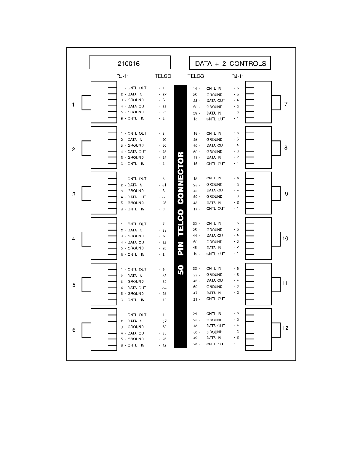
The CS modular splitter is wired as shown in Figure 3-8. Signal
names shown refer to those present on the CS telco connector.
Note that pins 49 and 50 of the 50-pin telco connector are connected
together and are used for signal ground.
Figure 3-7. CS Modular splitter
Page 35
Connecting Devices to CS and FM Ports 29
Figure 3-8. CS modular splitter wiring
Page 36
30 Equinox MEGAPORT Hardware Reference Manual
FM Modular Splitter
FM modular splitters are used with modular adaptors and modular
cables. This splitter converts the 100-pin MEGAPORT 12FM board
connector to a set of 12 RJ-45 modular jacks. Figure 3-9 illustrates
devices connected to the MEGAPORT using the FM modular splitter.
● The FM modular splitter (Equinox part number 990173)
converts the signals on the 100-pin connector to 12 RJ-45
modular jacks. This modular splitter is used to connect
the MEGAPORT board to ports requiring full modem
control.
● 10-wire modular cable must be used to attach devices to the
splitter.
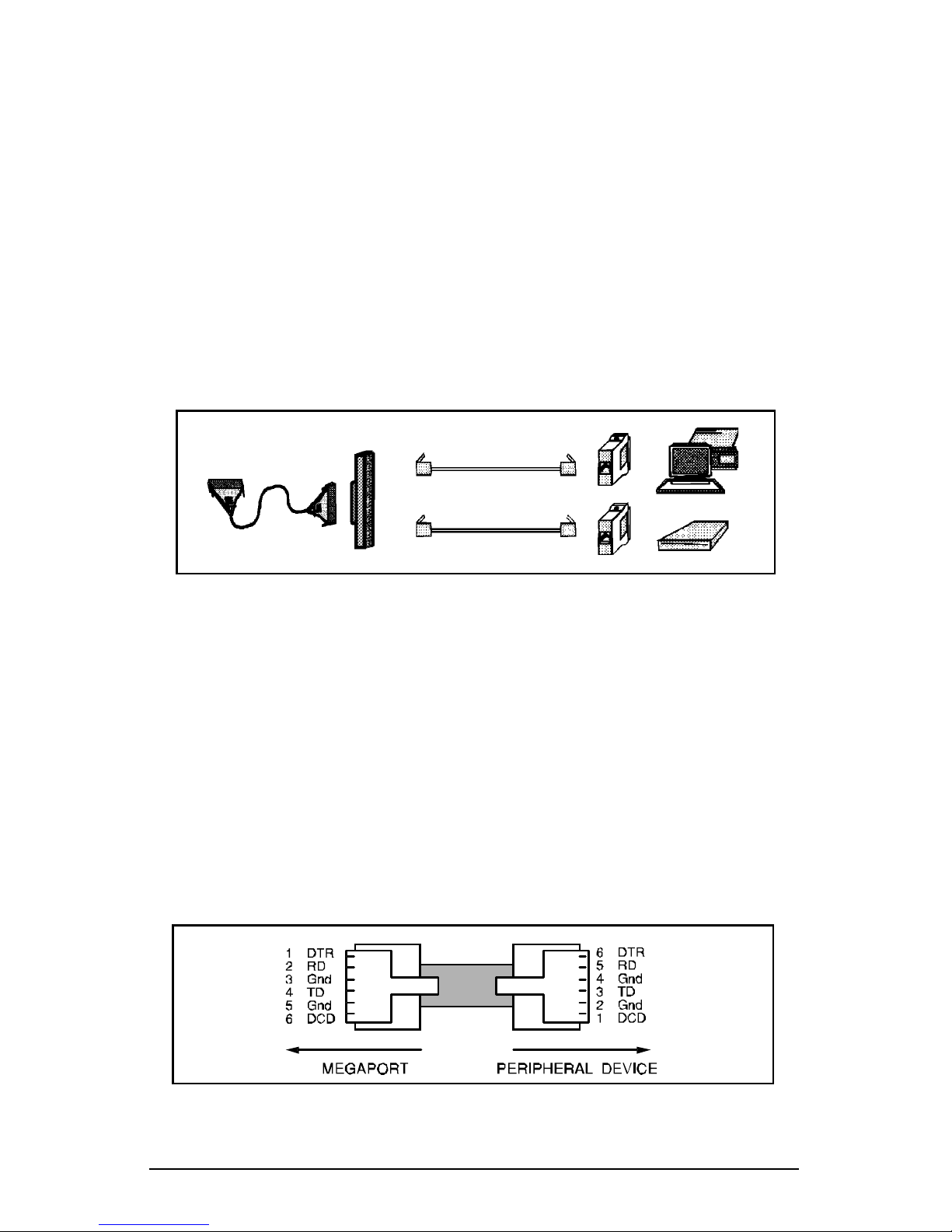
Figure 3-10. Modular cable signals
Modular Cables
RJ-11 modular cable is the flat cable used for wiring telephones
inside of buildings. The cable is terminated at each end with an RJ11 modular plug (connector) which is inserted into the modular jack
of an appropriate wiring module. Standard modular cables available
from Equinox or wiring distributors are reversing; that is the pins
are reversed on each end (so that pin 1 on one end is connected to
pin 6 on the opposite end, etc.). Figure 3-10 illustrates the signals
passed through modular cables when connected to a CS port using
the Equinox part number 210016 CS modular splitter.
Figure 3-9. FM Modular splitter
Page 37
Connecting Devices to CS and FM Ports 31
CS Modular Adaptors
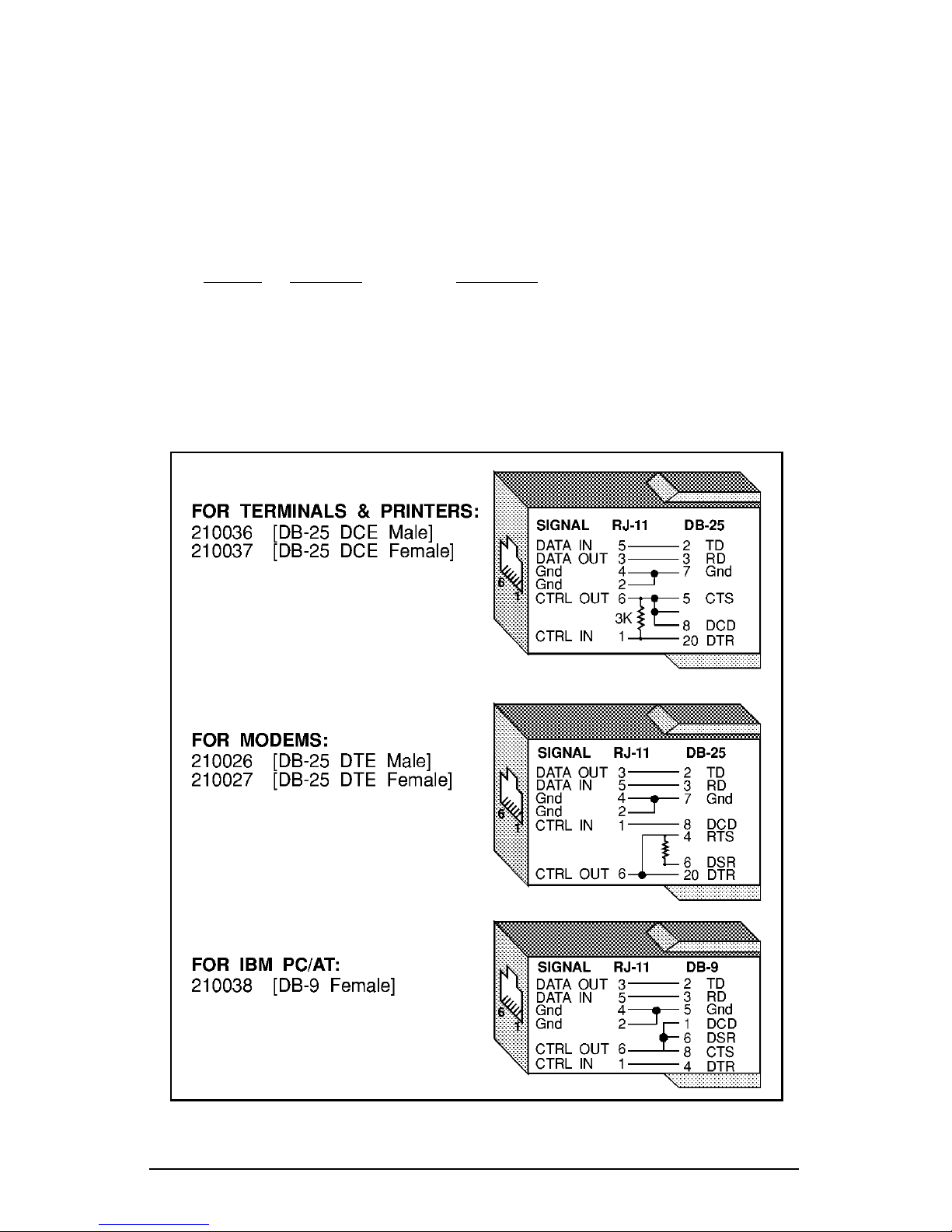
CS modular adaptors (see Figures 3-11) convert modular jacks to DB25 or DB-9 (RS-232) connectors. The following list describes the
modular adaptors available from Equinox. This list may be used to
determine the correct modular wiring accessories required for system
installation.
Part No. Connector Connect To
210036 DB-25 DCE male terminals or ports (female DTE )
210037 DB-25 DCE female terminals, ports, ISA PC, EISA PC (male DTE )
210026 DB-25 DTE male modems or multiplexer channels (female DCE )
210027 DB-25 DTE female Male DCE devices (non-standard devices)
210038 DB-9 female ISA PC serial port
Figure 3-11. CS Modular adaptors
Page 38

32 Equinox MEGAPORT Hardware Reference Manual
Note: When making modular adaptors, the 3K resistor shown
in Figure 3-10 may be eliminated for use with most terminals.
The resistor is used to loop control signals back to the attached
device when 4-wire cable is used and pin 6 is not connected.
When using 6-wire cable and there is a voltage on pin 6, the
resistor has no effect and the voltage on pin 6 is passed
through to the attached device.
FM Modular Adaptors
FM modular adaptors (see Figures 3-12) convert 10-pin RJ-45
modular jacks to DB-25 or DB-9 (RS-232) connectors. Some software
applications require the use of the Data Set Ready (DSR) signal. For
applications requiring DSR, use one of the following modular
adaptors or it's equivalent.
Part No. Connector Connect To
210068 DB-25 DTE male modems or multiplexer channels (female DCE )
210069 DB-25 DTE female Male DCE devices (non-standard devices)
210070 DB-25 DCE male terminals or ports (female DTE )
210071 DB-25 DCE female terminals, ports, personal computers (male DTE )
210072 DB-9 female personal computer serial port
Note: If the application does not require DSR, an 8-wire RJ-45
cable may be used.
Page 39

Connecting Devices to CS and FM Ports 33
RJ-45
10-Pin
RS-232
DB-25
RS-232
1
10
DSR
CTS
DCD
GND
TD
GND
RD
DTR
RTS
RI
DSR
CTS
DCD
TD
GND
RD
DTR
RTS
RI
1
2
3
4
5
6
7
8
9
10
6
5
8
2
7
3
20
4
22
RJ-45RS-232
DB-9
RS-232
1
8
TD
RD
GND
GND
DTR
CTS
RTS
DCD
RD
TD
GND
DSR
DCD
DTR
CTS
RTS
4
6
5
3
7
1
8
2
2
3
5
6
1
4
8
7
FOR MODEMS & MULTIPLEXERS:
210068 [DB-25 DTE Male]
210069 [DB-25 DTE Female]
FOR TERMINALS & PRINTERS:
210070 [DB-25 DCE Male]
210071 [DB-25 DCE Female]
FOR PERSONAL COMPUTERS:
210063 [DB-9 Female]
RJ-45
10-Pin
RS-232
DB-25
RS-232
1
10
DSR
CTS
DCD
GND
TD
GND
RD
DTR
RTS
RI
DTR
RTS
DCD
RD
GND
TD
DSR
CTS
RI
1
2
3
4
5
6
7
8
9
10
20
4
8
3
7
2
6
5
22
Figure 3-12. FM Modular Adaptors
Page 40
34 Equinox MEGAPORT Hardware Reference Manual
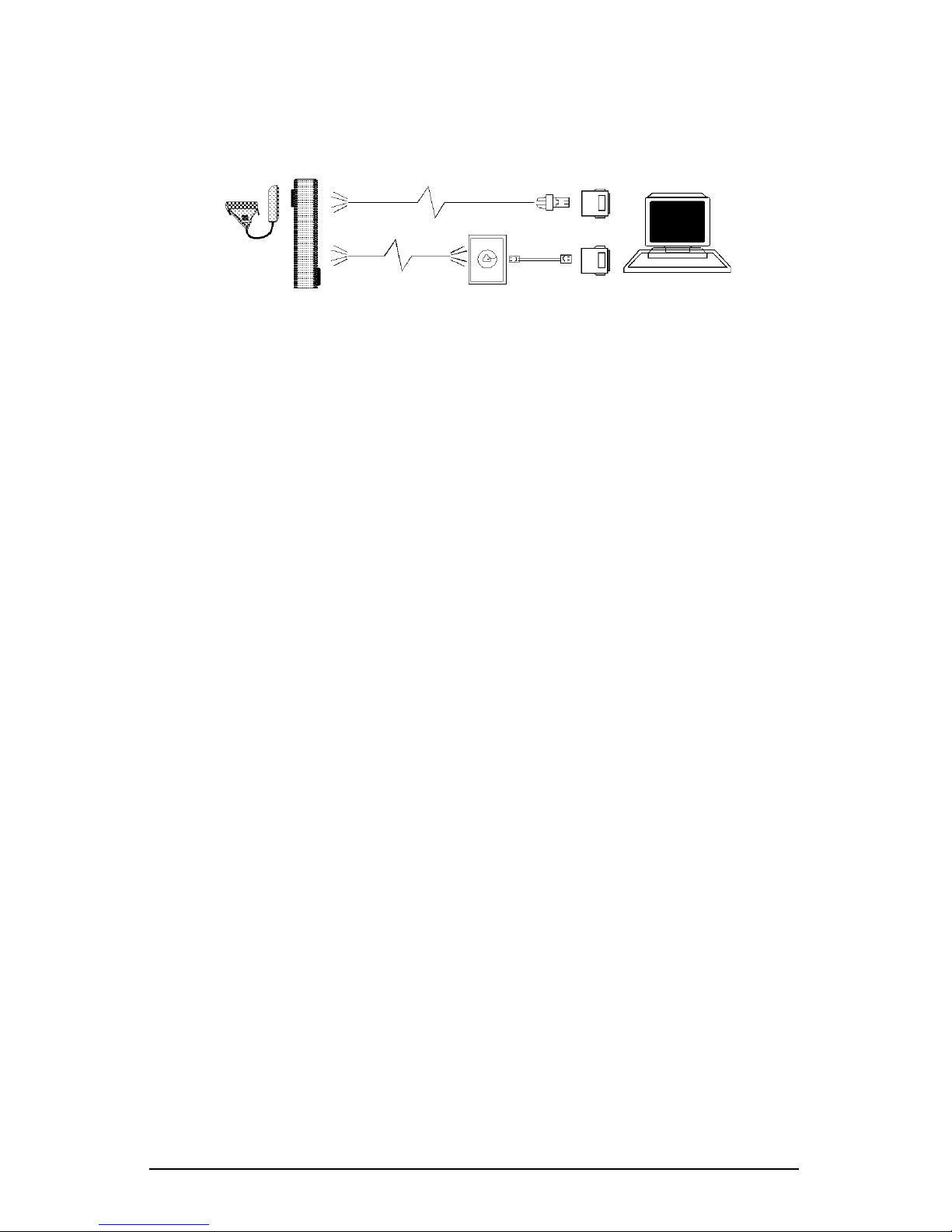
Punch Blocks
Punch blocks provide a quick and inexpensive solution to wiring
around buildings. They may be concealed in wiring closets and
individual wires run to each location where a terminal or port is to
be connected. Punch blocks may be used with modular wall outlets
and wiring accessories.
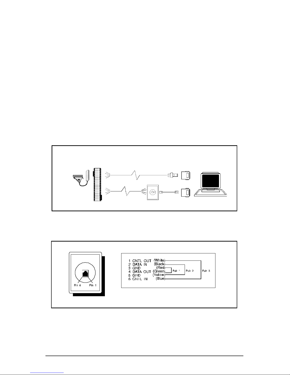
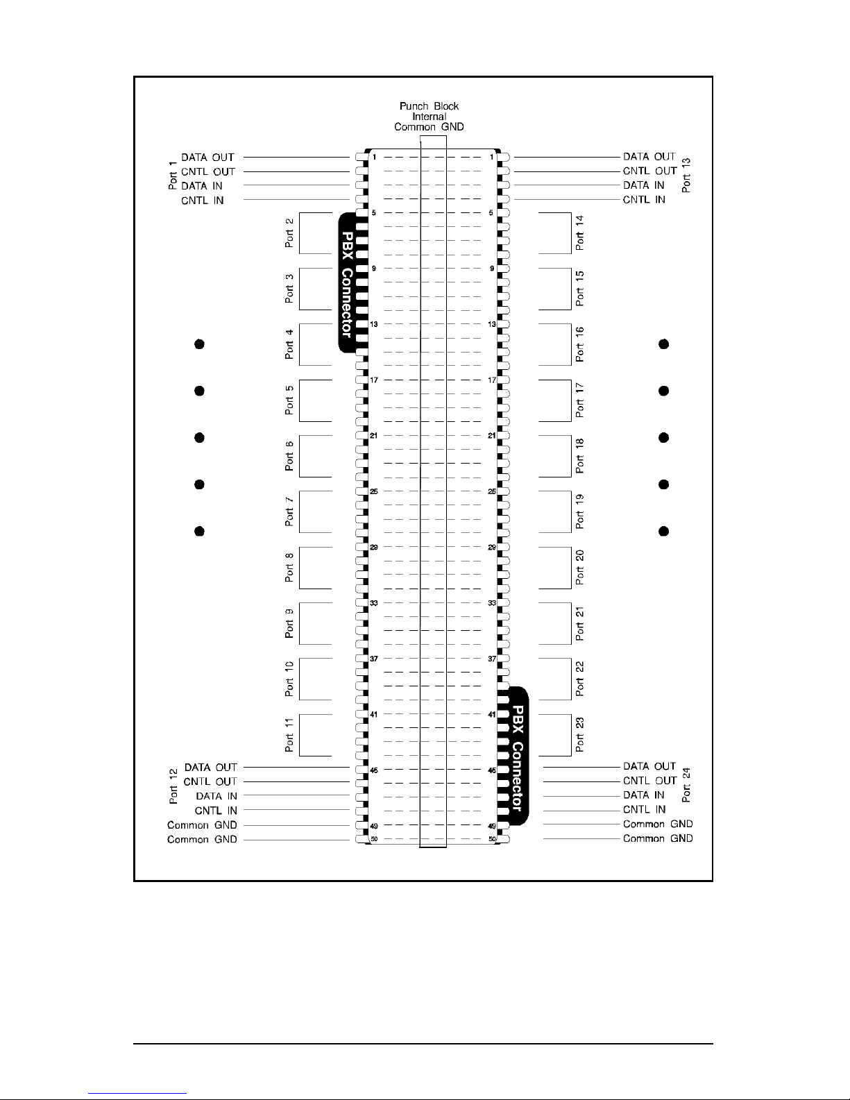
Figure 3-13 illustrates connecting the MEGAPORT board to punch
blocks using modular adaptors and modular wall outlets. Wall
outlets should be wired as shown in Figure 3-14. Figure 3-15 shows
the pinouts for the Equinox part number 210044 punch block when
connected to a MEGAPORT CS board.
Note that the punch block has two 50-pin PBX connectors and
connects 24 ports. Also note that internally the punch block has
common ground wired to the center two rows of pins. Any of these
pins may be used for connecting terminal ground to the port.
Figure 3-14. Modular wall outlet wiring: CS ports
Modular
Adaptors
Modular
Cables
Wall Outlets
Punch
Block
Figure 3-13. Punch block installations
Page 41
Connecting Devices to CS and FM Ports 35
Figure 3-15. Punch block (PN 210044) wiring: CS ports
Page 42
36 Equinox MEGAPORT Hardware Reference Manual
CS Port Full Modem Control Wiring
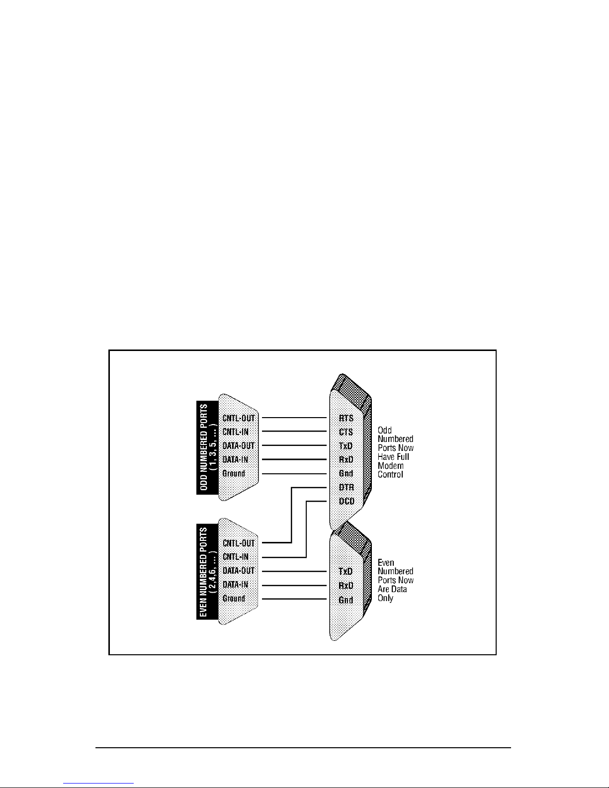
As discussed above, MEGAPORT CS ports regularly provide two
modem control signals per port (i.e. CNTL OUT and CNTL IN),
which may be used for either modem supervision (DTR/DCD) or
hardware flow control (RTS/CTS), under software control.
The combination of various software flags and some special signal
rerouting (the “borrowing” of two control signals from a neighboring
“donor” port) provides the additional two signals. Up to one half of
the CS ports on a board can thus be used for devices requiring full
modem control, leaving the remaining ports available for use with
terminals and printers.
Figure 3-16 shows the wiring needed to connect a donor port’s
control signals to a full modem control recipient port. Equinox offers
several full modem control wiring accessories which provide both
sets of signals. They are outlined below.
Figure 3-16. Full modem control signal rerouting
Page 43
Connecting Devices to CS and FM Ports 37
Modular Full Modem Control Adaptor
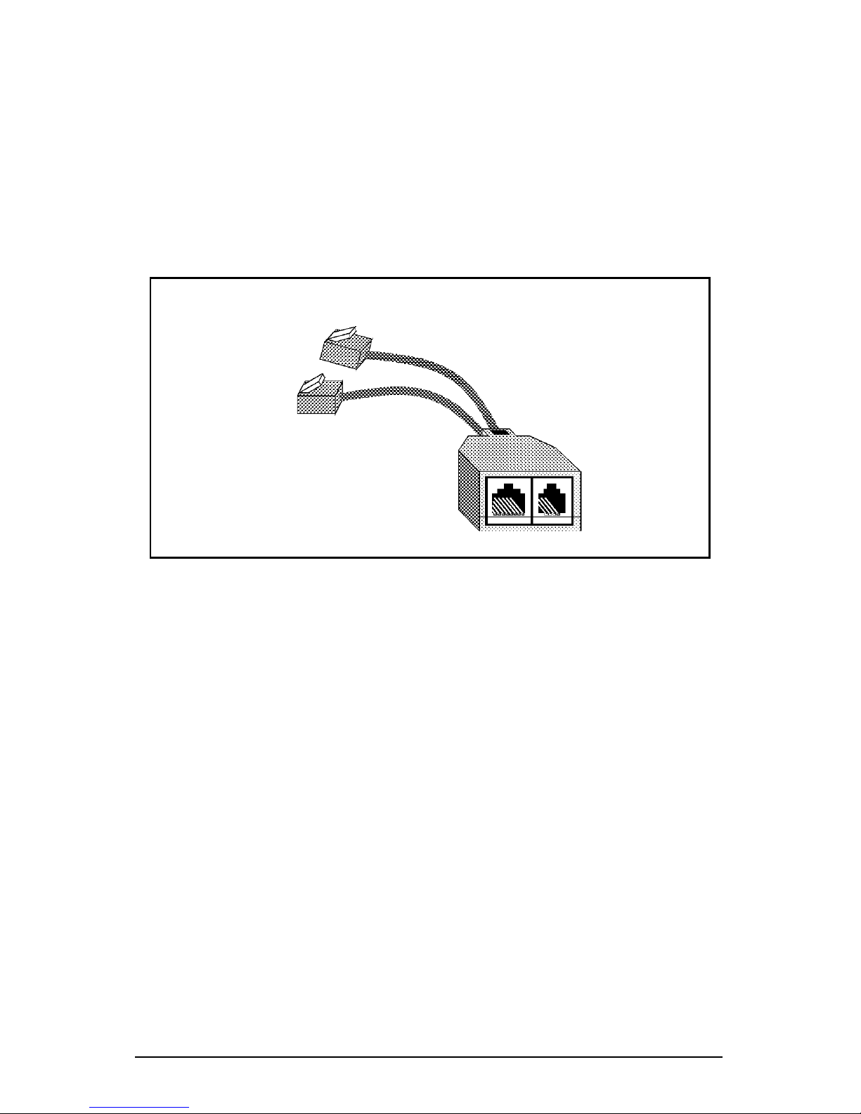
To implement full modem control in a modular environment, Equinox provides modular full modem control adaptors. These devices
consist of two short cables which are plugged into the appropriate
adjacent port jacks on an Equinox modular splitter. At the end of
the cables is a small housing with two jacks, one providing full
modem control and the other data only (see Figure 3-17). Refer to
the Equinox Ordering Guide for available adaptors and their part
numbers.
8-wire RJ-45
Full Modem Control
4-wire RJ-11
Data Only
To Modular
Splitter
To even
numbered ports
To odd
numbered ports
Figure 3-17. Modular full modem control adaptor (PN 690242)
Page 44

38 Equinox MEGAPORT Hardware Reference Manual
Special Considerations
When connecting devices to the MEGAPORT board ports, it is
important to understand the difference between DCE and DTE
devices. This is to ensure that data flows in the right direction. If
DCE and DTE are not wired correctly, communications between the
two devices may be blocked.
DCE - Data Communications Equipment such as modems.
DTE - Data Terminal Equipment such as terminals and
printers.
It is also important to understand the difference in terminology
between DB-25 and modular wired installations.
Wiring Conventions
In general, with conventional wiring, DTE devices can only be
connected to DCE devices. This ensures, for example, that the
output of the terminal is routed to the input of the modem. For
example, computer terminals (DTE devices) should be connected to
DCE ports, such as the 990117 DB-25 distribution panel and the
210036 modular adaptor.
This is performed (1) in DB-25 environments with conventional,
straight through cables, and, (2) in the modular environment with
single reversing modular cables and one modular adaptor.
Non-Conventional Wiring
In some situations, it may be necessary to do a non-conventional
interconnection. It is possible to connect DTE devices to other DTE
devices and DCE devices to other DCE devices. For example, if two
terminals or ports must be placed back-to-back without intervening
modems.
This is done in DB-25 environments with null modem cables.
Page 45
Connecting Devices to LD Ports 39
CHAPTER 4
CONNECTING DEVICES TO LD PORTS
This chapter applies equally to MEGAPORT, MEGAPORT/2 and
MEGAPORT/RS and explains the cabling options which may be used
to connect devices to:
● the MEGAPORT 12LD board,
● the MEGAPORT 24LD board,
● the first group of twelve ports (i.e. ports numbered 1
through 12) on the MEGAPORT 12LD+12CS board. (The
first group of twelve ports on the MEGAPORT 12LD+12CS
board are identical to the corresponding ports on the 12LD
and 24LD boards.)
These ports are all of the LD type and can be used at high speed with
standard RS-232, RS-422 and RS-423 devices for long distance cable
runs without any special devices at the terminal end. In addition, LD
ports have built in surge suppression for protecting the port from
damage due to voltage transients.
NOTE: The information in this chapter should not be used to
connect devices to MEGAPORT 12CS, MEGAPORT 24CS
boards or to connect devices to the second group of twelve ports
on the MEGAPORT 12LD+12CS boards. For information on
connecting to these ports please refer to Chapter 3, Connecting
to CS Ports.
12LD 24LD (or 12LD+12CS)
Page 46
40 Equinox MEGAPORT Hardware Reference Manual
To assist in the wiring of the MEGAPORT board, Equinox sells a
complete set of cabling accessories. See an Equinox Ordering Guide
for more information.
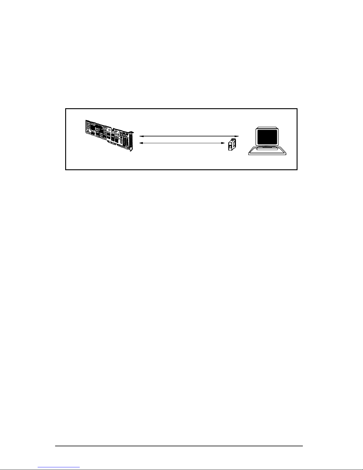
As shown in Figure 4-1, standard RS-232 devices may be connected to
LD ports and operate reliably at 38.4 Kbps over standard two-twistedpair cable at distances up to 1000 feet without requiring a line driver
on the terminal end.
If an Equinox LDA-232 terminal powered line driver is used at the
terminal end the distance is increased to 3000 feet. The LDA-232 also
provides surge suppression on the terminal end.
Even greater distances can be achieved at lower bit rates. At 19.2
Kbps both distances double and at 9600 bps they double again.
However, special care must be taken in connecting devices to LD
ports to obtain these distances.
Complete details about LD ports may be found in Equinox Technical
Note #1, Equinox part number 302024, a copy of which is enclosed
with all MEGAPORT LD boards.
1000 feet at 38.4 Kbps
without line driver
3000 feet at 38.4 Kbps
with LDA-232 at terminal end
Figure 4-1. LD Port application.
Page 47

Connecting Devices to LD Ports 41
LD Port Signals
Signal Names
The names of signals on the telco connectors of the MEGAPORT ports
indicate the direction of the signals. They are either inbound
(received by MEGAPORT) or outbound (transmitted from
MEGAPORT).
Data Signals
Each LD port uses two twisted-pairs. Data is transmitted from
the port on one pair and received on the other.
DATA IN(+) and DATA IN(-) indicates data received by the
MEGAPORT board from the attached device (inbound). DATA
IN(-) is normally connected to TxD (Transmit Data) for terminals and printers. DATA IN(+) is connected to ground on the
terminal or printer.
DATA OUT(+) and DATA OUT(-) indicates data transmitted by
the MEGAPORT board to the attached device (outbound).
DATA OUT(-) is normally connected to RxD (Receive Data) for
terminals and printers. DATA OUT(+) is connected to ground
on the terminal or printer.
EIA Control Signals
No EIA modem control signals are provided on LD ports.
Conversion to RS-232 Signal Names
The conversion to RS-232 from the LD telco connector pinouts and
MEGAPORT signal names, DATA IN(+), DATA IN(-), DATA OUT(+)
AND DATA OUT(-), is accomplished with one of the Equinox cabling
accessories. These accessories and wiring techniques are discussed in
Chapter 3 under the heading Wiring to Terminal Devices.
Page 48
42 Equinox MEGAPORT Hardware Reference Manual
Telco Connector Pinouts
The following paragraphs list the cable pinouts of the LD ports. The
physical ports are mapped by the device driver into the appropriate
device names.
MEGAPORT 12LD Board Telco Connector Pinouts
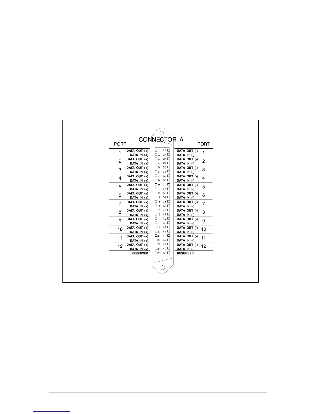
Figure 4-2 shows the wiring of the telco connector on the MEGAPORT
12LD board. A single cable provides all the signals required for
supporting 12 ports.
Figure 4-2. MEGAPORT 12LD telco connector pinouts.
Page 49
Connecting Devices to LD Ports 43
MEGAPORT 24LD Board Telco Connector Pinouts
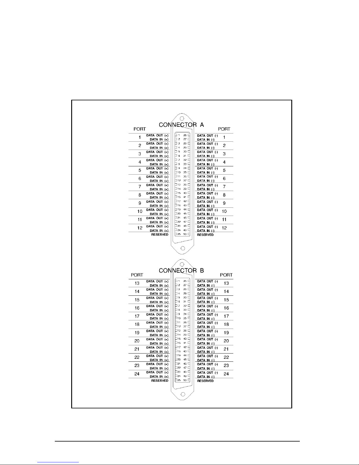
The wiring of the telco connectors on MEGAPORT 24LD board is
shown in Figure 4-3. Connector A provides LD ports 1-12 and is
identical to the MEGAPORT 12LD connector. Connector B provides
LD ports 13-24.
Figure 4-3. MEGAPORT 24LD telco connector pinouts.
Page 50
44 Equinox MEGAPORT Hardware Reference Manual
MEGAPORT 12LD+12CS Board Telco Connector Pinouts
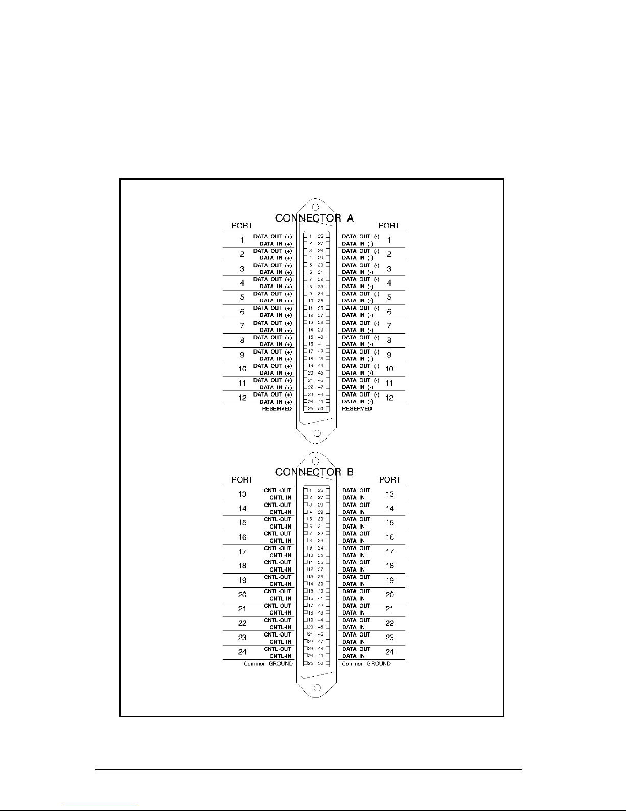
The wiring of the telco connectors on the MEGAPORT 12LD+12CS
board is shown in Figure 4-4. Connector A provides LD ports 1-12
and is identical to the MEGAPORT 12LD connector. Connector B
provides CS ports 13-24 and is identical to the Connector B of the
MEGAPORT 24CS connector (see Chapter 3).
Figure 4-4. MEGAPORT 12LD+12CS telco connector pinouts.
Page 51

Connecting Devices to LD Ports 45
Wiring to Terminal Devices
Complete details about LD ports may be found in Equinox Technical
Note #1, MEGAPORT LD: Exploring Long Distance Connections to
Terminals and Printers, Equinox part number 302024, a copy of
which is enclosed with all MEGAPORT LD boards. This publication
also addresses various other features of the LD products line.
LD Cabling Issues
The long distance capability of the LD interface is due to the high
noise rejection provided by twisted pair cable and the bipolar data
signals used by the LD interface. This interface requires the following rules be obeyed in cabling LD ports to devices.
1. It is extremely important that twisted-pair wiring be used
for connecting devices to the ports. To realize the maximum
distance at the highest speed, minimize or avoid the use of
modular flat telephone cable (which does not provide
twisted-pairs).
2. The two input signals: DATA IN(+) and DATA IN(-) must
reside in the same twisted pair. Also, the two output
signals: DATA OUT(+) and DATA OUT(-) must share their
own twisted pair.
Page 52

46 Equinox MEGAPORT Hardware Reference Manual
LD Cabling Schemes
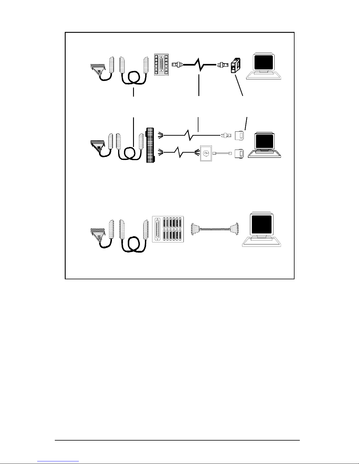
There are two recommended cabling schemes for connecting devices
to MEGAPORT LD ports. Both methods are illustrated in Figure 4-5.
The first scheme uses 25 pair telco extension cables for the long
distance portion of the cable run and then uses the Equinox 210117
LD modular splitter to connect a group of ports in close proximity to
each other to the MEGAPORT.
The second scheme uses a telephone punch block to interface the
MEGAPORT with the individual two-twisted-pair cables that are run
to modular wall outlets.
Both schemes have their advantages and disadvantages. The Equinox pinouts match standard telephone cabling practices. Thus, when
planning an installation in a new building, a telephone installer can
connect wall outlets to punch block and the MEGAPORT round cable
telco connector can be connected to the punch block directly, with no
special consideration on the part of the installer to its use for data
instead of voice. Alternatively, the modular splitter is useful when a
number of devices located some distance (i.e. in another building) are
required to be connected to the MEGAPORT.
CAUTION
Cabling Between Buildings
When connecting devices to LD ports located in another
building, the potential for lightning induced surges is
highly likely, especially if the wiring is unprotected.
This is usually caused by a shift in the ground potential
between the two buildings. The LD ports are protected
due to their on-board surge suppression. However, the
surge can be transmitted to the device connected to the
LD port, with a high probability of damage occurring.
To protect terminals and other devices connected to LD
ports, Equinox strongly recommends the use of the
Equinox LDA-232 on the terminal side. The surge
suppression on the LDA-232 should protect the terminal
equipment in this case, although in severe cases the
LDA-232 may be sacrificed in place of the terminal
equipment.
Page 53
Connecting Devices to LD Ports 47
50-pair PBX
extension cables
for long distance
Two-twisted-pair cable
OR Modular cable for
up to 50 feet
Modular
adaptor or
LDA-232
LD Modular Splitter (PN
210117)
Punch block
(PN 210044)
Wall outlet
50-pair PBX
extension cables
for long distance
DB-25
distribution
panel (PN
990117)
Specially
wired RS-232
Cable
Figure 4-5. MEGAPORT LD cabling methods.
Page 54
48 Equinox MEGAPORT Hardware Reference Manual
DB-25 Wiring
Although not highly recommended by Equinox, it is possible to
use DB-25 type connectors with LD ports. This is especially
useful where existing wiring is to be used.
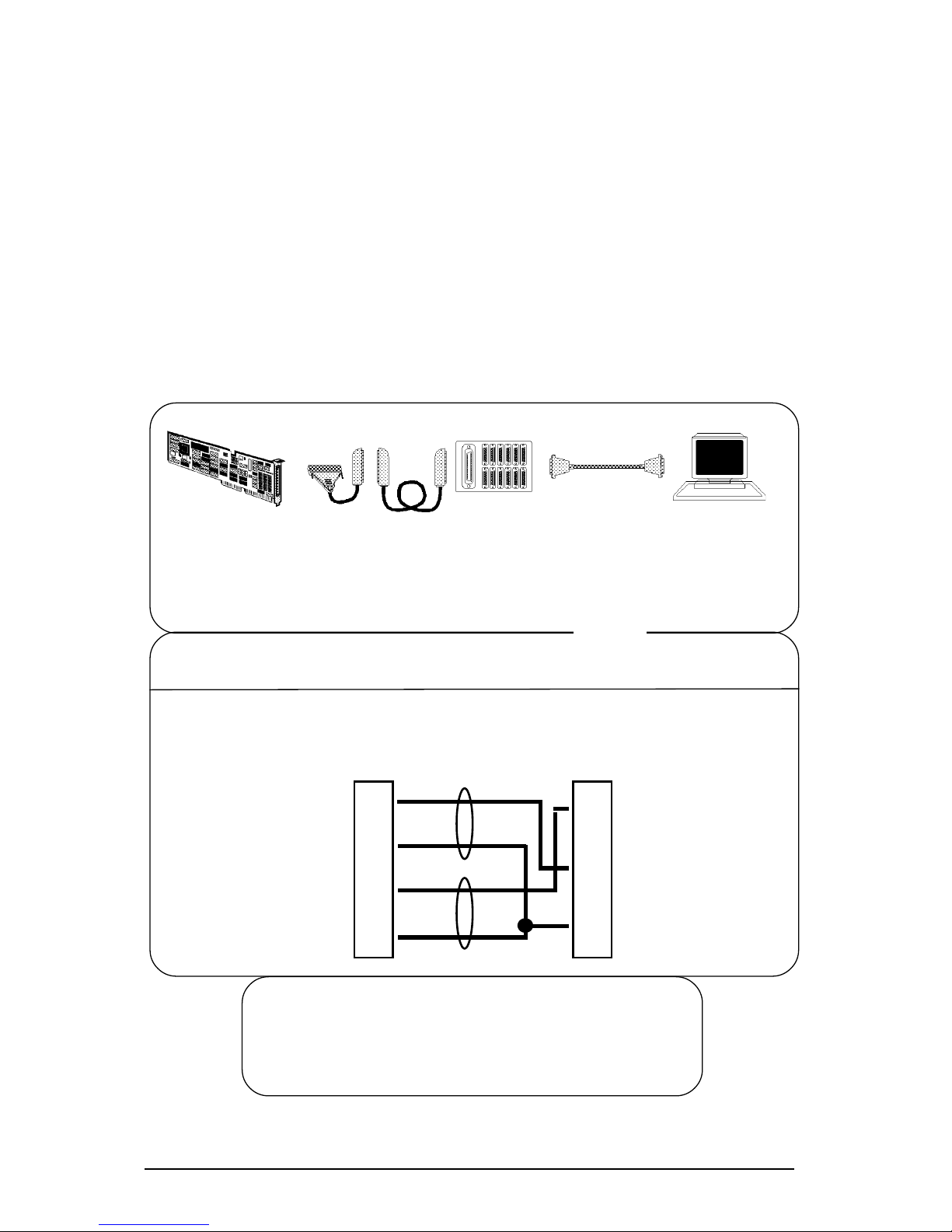
Figure 4-6 shows the cable connections for the distribution
panel between a MEGAPORT board and a terminal or printer.
The cable(s), provided with the LD board, must be used between
the DB-25 distribution panel (part number 990117) and the
MEGAPORT board. The specially wired cable to the terminal or
printer is not provided by Equinox. However, all necessary
RS-232 wiring information is detailed below under Special
Cable Pinouts.
Figure 4-6. MEGAPORT LD DB-25 wiring.
Terminal or
Printer
990117
Distribution Panel
End
DATA OUT(-) 3
DATA OUT(+) 8
DATA IN(-) 2
DATA IN(+) 20
2 TD
3 RD
7 Gnd
Pair 2
Pair 1
Terminal
or Printer
End
Note: In the cable, pairs 3/8 and 2/20 must be
twisted pairs. A 4-wire cable is required.
Connection of DATA OUT(+) and DATA IN(+)
must be done only at terminal or printer end.
➪➪
➪➪
➪
Special Cable Pinouts
Any LD Board
MEGAPORT Cable(s)
w/Telco Connector
Specially wired
RS-232 Cable
990117
Distribution
Panel
Page 55
Connecting Devices to LD Ports 49
Modular Wiring
LD Modular Splitter
Modular splitters are used with modular adaptors and modular cable.
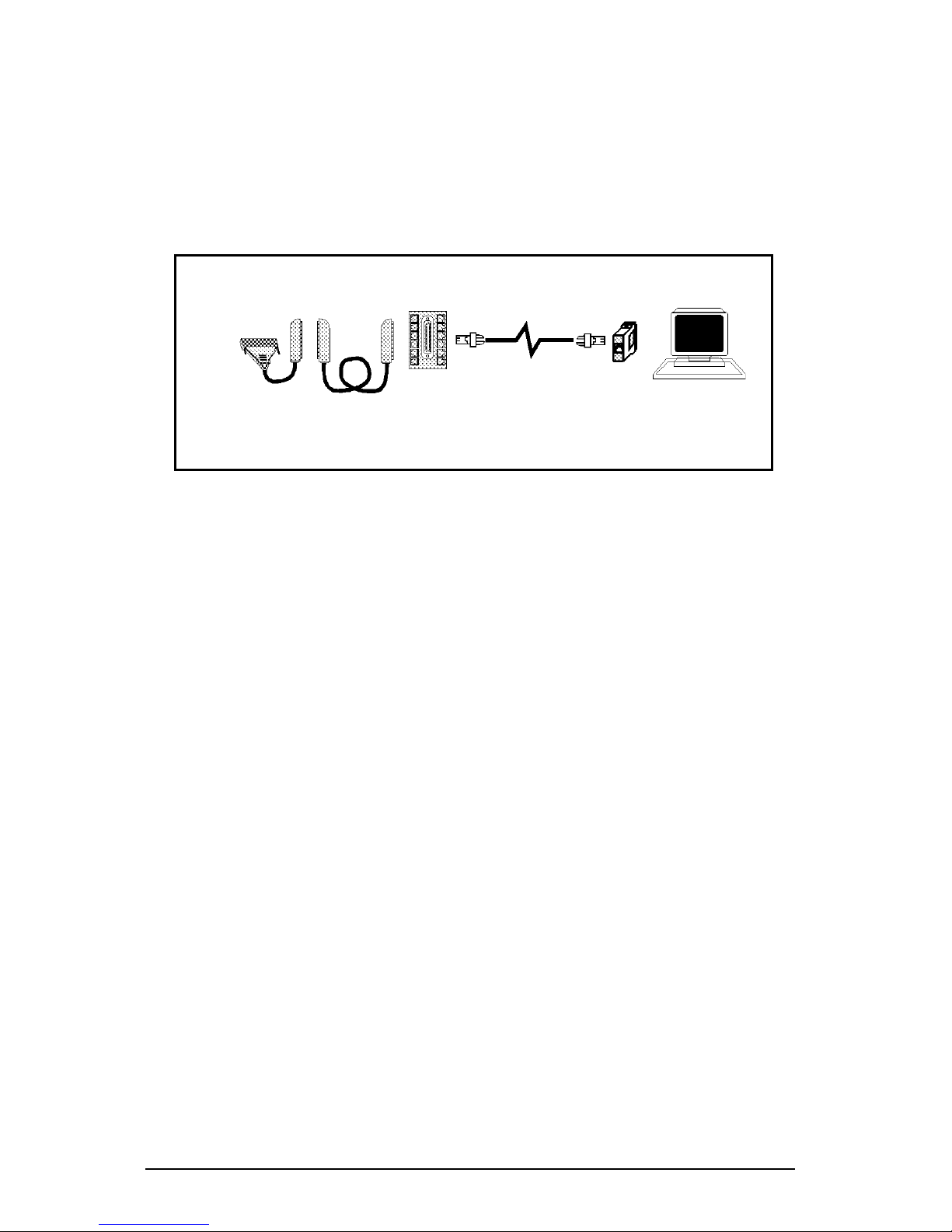
Modular splitters convert the 50-pin telco connector to a set of 12
modular jacks. Figure 4-7 illustrates devices connected to the
MEGAPORT board using the modular splitter.
LD Modular Splitter (PN
210117)
● The LD modular splitter (Equinox part number 210117)
converts the signals on the 50-pin connector to 12 RJ-11
modular jacks. This splitter must be used to connect to LD
ports. A CS version of the modular splitter (Equinox part
number 210016) is available for connecting devices to CS
ports. Two modular splitters are required to connect 24
devices to one MEGAPORT board. The modular splitter is
wired as shown in Figure 4-8.
● Only 4 wires are used, so either 4- or 6-wire modular cable
may be used to attach devices to the splitter. When user
supplied modular cable is used, make sure the cable is
reversing. Standard telephone cords are made this way and
can be used for this application.
● Modular adaptors convert modular plugs at the end of
modular cables to DB-25 RS-232 connectors. One adaptor is
required for each device to be connected. The adaptors for
MEGAPORT LD boards are the same as for CS boards.
Figure 4-7. LD modular splitter.
Modular
adaptor or
LDA-232
Two-twisted-pair cable
OR Modular cable for
up to 50 feet
50-pair PBX
extension cables
for long distance
Page 56

50 Equinox MEGAPORT Hardware Reference Manual
Figure 4-8. LD modular splitter wiring.
Page 57
Connecting Devices to LD Ports 51
Modular Cables
RJ-11 modular cable is the flat cable used for wiring telephones inside
of buildings. The cable is terminated at each end with an RJ-11
modular plug (connector) which is inserted into the modular jack of
an appropriate wiring module. Standard modular cables available
from Equinox or wiring distributors are reversing; that is the pins are
reversed on each end (so that pin 1 on one end is connected to pin 6 on
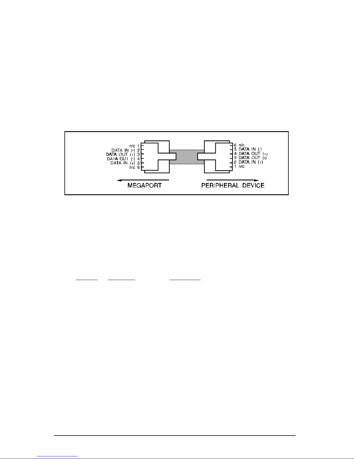
the opposite end, etc.). Figure 4-9 illustrates the signals passed
through modular cables when connected to a LD port using the
Equinox part number 210117 LD modular splitter.
Modular Adaptors
Modular adaptors convert modular jacks to DB-25 (RS-232) connectors. The following list describes the modular adaptors available from
Equinox. This list may be used to determine the correct modular
wiring required for system installation
Part No. Connector Connect To
210036 DB-25 DCE male terminals or ports (female DTE )
210037 DB-25 DCE female terminals, ports, IBM PC, XT, PS/2 (male DTE )
210026 DB-25 DTE male modems or multiplexer channels (female DCE)
210027 DB-25 DTE female Male DCE devices (non-standard devices)
210038 DB-9 female IBM PC AT serial port
Note: Although modems can be connected to LD boards, it is not
recommended because LD boards do not support control signals.
Figure 4-9. LD Modular cable signals.
Page 58
52 Equinox MEGAPORT Hardware Reference Manual
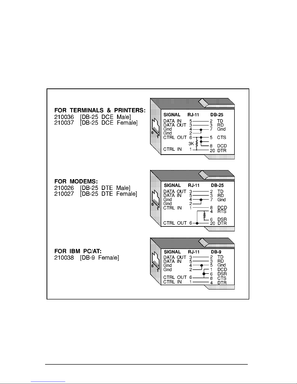
Modular adaptor wiring is shown in Figure 4-10. When making
modular adaptors, the 3K resistor shown may be eliminated for use
with most terminals. The resistor is used to loop control signals back
to the attached device when 4-wire cable is used and pin 6 is not
connected. When using 6-wire cable and there is voltage on pin 6 the
resistor has no effect and the voltage on pin 6 is passed through to
the attached device.
Figure 4-10. Modular adaptors
Page 59
Connecting Devices to LD Ports 53
Punch Blocks
Punch blocks provide a quick and inexpensive solution to wiring
around buildings. They may be concealed in wiring closets and
individual wires run to each location where a terminal or port is to be
connected. Punch blocks may be used with modular wall outlets and
wiring accessories.
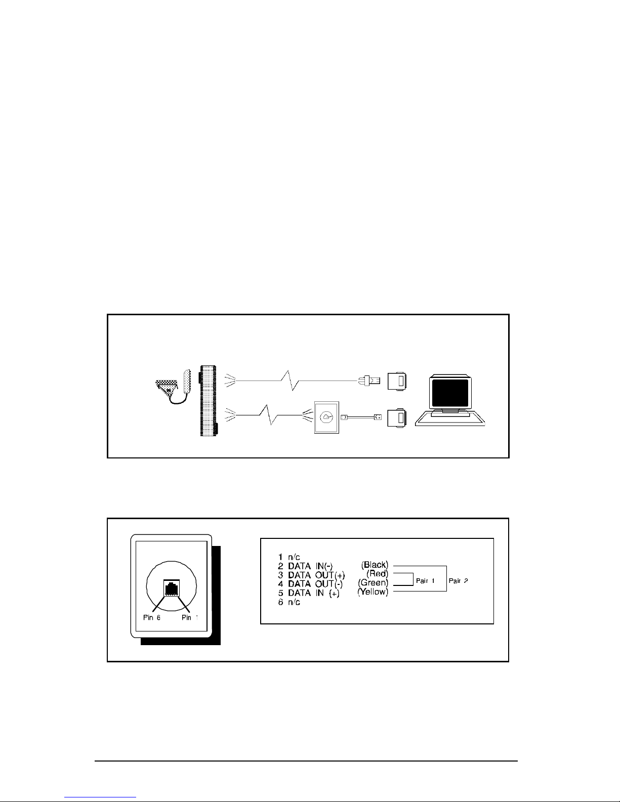
Figure 4-11 illustrates connecting the MEGAPORT board to punch
blocks using modular adaptors and modular wall outlets. Wall outlets
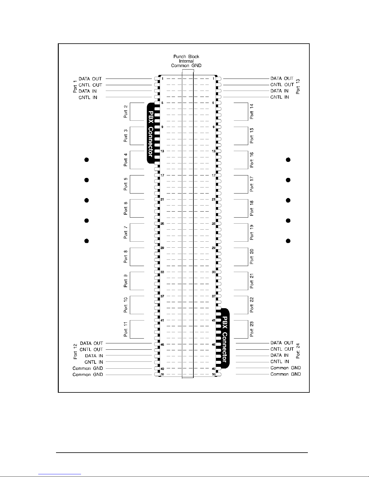
should be wired as shown in Figure 4-12 below. Figure 4-13 shows
the pinouts for the Equinox part number 210044 punch block when
connected to a MEGAPORT LD board.
Note that the punch block has two 50-pin PBX connectors and
connects 24 ports. Also note that internally the punch block has
common ground wired to the center two rows of pins. In LD
applications these pins are not used.
Figure 4-12. Modular wall outlet wiring: LD ports.
Two-twisted-pair
or modular
cables
Punch
Block
Modular
Adaptors
Wall Outlets
Figure 4-11. Punch block Installations.
Page 60
54 Equinox MEGAPORT Hardware Reference Manual
Figure 4-13. Punch block (PN 210044) wiring: LD ports.
Page 61

Document Change Request 55
APPENDIX A
DOCUMENT CHANGE REQUEST
At Equinox we are always striving to make our product manuals accurate
and easy to use. If you have an improvement to suggest or find an error
in this manual please let us know.
Manual: MEGAPORT Hardware Reference Manual (560047/B)
Operating System and Version: _________________________________
Driver Version: ______________________________________________
Problem:
Solution:
What could be added or changed to make the manual better?
Name: Title:
Company: Phone:
Send to: Equinox Systems Inc.
ATTN: Customer Service
One Equinox Way
Sunrise, FL 33351-6709
954-746-9000, Fax: 954-746-9101
Page 62

56 Equinox MEGAPORT Hardware Reference Manual
Page 63

Technical Support Procedures 57
APPENDIX B
TECHNICAL SUPPORT PROCEDURES
Equinox makes every effort to ensure that your MEGAPORT board is of
top quality in all respects. If you have a problem with your MEGAPORT
board we ask you to follow these steps before you call:
●
Read the appropriate hardware and software reference
manuals and any release notes which describe the procedure you are trying to perform.
●
Check the Equinox MEGAPORT Bulletin Board System. To
access the board, simply call (954) 746-0282 with any speed
modem and use N-8-1 or E-7-1 parameters. Just follow the
prompts to answer a few identifying questions.
●
Contact the distributor from whom you purchased the
board. Equinox authorized distributors are fully trained on
MEGAPORT and MEGAPLEX products and are authorized
to handle technical support, service, returns and warranty
claims.
●
If you still need assistance after calling your distributor or
other point of purchase, call Equinox Technical Support at
(954) 746-9000. You can also fax problem reports, bugs,
questions to us at (954) 746-9101. Please have the following information available when you call:
Board Type:
Serial Number:
Date of Purchase:
Place of Purchase:
Operating System:
Operating System Version:
Device Driver Version:
Computer Make & Model:
Other Boards in Machine:
Description of Problem:
Page 64

58 Equinox MEGAPORT Hardware Reference Manual
Page 65

Index 59
Index
Symbols
10-pin RJ-45 ...................................... 32
10-wire ............................................... 30
12 FM Splitter ................................... 2 4
12CS pinouts ..................................... 21
12LD pinouts ..................................... 42
12LD+12CS pinouts ................... 23, 44
210026 ......................................... 31, 32
210027 .................................. 31, 32, 5 1
210036 .................................. 31, 32, 5 1
210037 .................................. 31, 32, 5 1
210038 ................................................ 51
210044 ......................................... 34, 53
210068 ................................................ 32
210069 ................................................ 32
210070 ................................................ 32
210071 ................................................ 32
210072 ................................................ 32
210117 ......................................... 46, 51
24CS pinouts ..................................... 22
24LD pinouts ..................................... 43
650053 .................................................. 6
650074 .................................................. 6
650078 .................................................. 6
650079 .................................................. 6
650089 .................................................. 6
66-type punch blocks ........................ 3 4
990117 ......................................... 27, 48
990121 ................................................ 27
990122 ................................................ 27
A
Adapter Description File .................. 15
Adaptors
full modem control .................. 37
modular ......................................
25, 31, 33, 34, 49, 51, 53
making your own ................32
ADF .................................................... 15
B
Bulletin Board System...................... 57
Bus. See specific bus type
C
Cables
extension ...................18, 46, 47
modular ........28, 30, 45, 49, 51
reversing .......................... 30, 51
twisted pair .............................48
two-twisted-pair ...................... 47
Cabling accessories ........................... 4 1
Cabling between buildings ............... 4 6
CNTL IN ..................................... 20, 36
CNTL OUT ................................. 20, 3 6
Connecting to CS ports ............... 19–31
Connecting to LD ports............... 39–52
Control signal borrowing.................. 36
Control signals ........................... 20, 41
Conversion to RS-232 ....................... 4 1
CS 3, 19–31, 36
CS modular splitter ................... 28, 30
wiring...................................... 29
CS ports
connections....................... 19–31
D
Data Communications Equipment .. 38
DATA IN ....................... 20, 41, 45, 48
DATA OUT ................... 20, 41, 45, 4 8
Data Set Ready.................................. 32
Data signals ................................ 20, 4 1
Data Terminal Equipment ............... 3 8
DB-25 .......................................... 18, 3 2
DB-25 distribution panels ................ 27
Page 66

60 Equinox MEGAPORT Hardware Reference Manual
DB-25 wiring
CS ports ..................................2 5
LD ports ..................................4 8
DB-9 ................................................... 32
DCE .................................................... 38
Devices
connecting to CS ports ...... 19–31
connecting to LD ports ...... 39–52
Distribution panel wiring .................2 7
Distribution panels ...........................2 5
DB-25 .....................................27
Donor port.......................................... 36
Driver kit .............................................6
DSR ....................................................3 2
DTE ....................................................38
DTR/DCD ...................................... 3, 36
E
EISA
bus ......................................... 10
installation......................... 9, 10
jumper ....................................10
Equinox Bulletin Board System ...... 57
Extension cables.................. 18, 46, 47
F
Florida Datamation ............................ 6
Flow control
hardware................................. 36
FM ......................................... 3, 18, 1 9
FM Modular Adaptors ......................3 2
FM Port Signals ................................2 4
full modem ......................................... 19
full modem control ............................ 30
Full modem control adaptor
modular .................................. 37
Full modem control wiring............... 3 6
G
Ground potential shift ......................4 6
I
IBM PC AT serial port...................... 51
Installation
MEGAPORT/2.................. 15, 17
multiple boards .......................1 3
round cable............................. 18
Interconnect cable .............................1 3
Intermixng products ......................... 1 0
L
LD ..................................................... 39
LD boards ............................................7
LD cabling.......................................... 46
LD modular splitter ............ 46, 49, 51
LD modular splitter wiring .............. 50
LD port connections .................... 39–52
LDA-232................................. 3, 40, 47
Lightning ........................................... 4 6
Line driver .................................... 3, 4 0
Long distance ............................. 39, 45
M
Making your own modular adaptors 5 2
MEGAPLEX ...................................... 10
MEGAPORT ........................................4
MEGAPORT 12CS ............................1 9
MEGAPORT 12FM .............. 1, 3, 4, 5
MEGAPORT 12FM board................. 19
MEGAPORT 12LD+12CS................. 19
MEGAPORT 24CS ............................1 9
MEGAPORT 8CS .............................. 10
MEGAPORT/2 .. 4, 13, 15, 17, 19, 39
MEGAPORT/2 12FM ................ 2, 4, 6
MEGAPORT/RS . 1, 2, 13, 17, 19, 39
Modem control signals ................. 3, 19
Modem supervision ........................... 3 6
Modular adaptors..................................
20, 25, 31, 33, 34, 49, 51, 53
full modem control .................. 37
making your own ............. 32, 52
pinouts ...................................52
Modular cables 25, 28, 30, 45, 49, 51
Modular full modem control adaptor3 7
Modular splitter wiring
LD ...........................................50
Modular splitters........................ 25, 46
CS .................................... 28, 30
LD ...........................................49
Modular wall outlets.... 26, 34, 46, 53
Modular wiring.................................. 25
N
Noise rejection................................... 4 5
Non-conventional wiring .................. 3 8
Null modem cables............................ 3 8
O
Option Diskette ................................. 15
Ordering Guide .......................... 19, 4 0
Page 67

Index 61
P
PC AT serial port .............................. 51
Pinouts
12CS....................................... 21
12LD....................................... 42
12LD+12CS...................... 23, 44
24CS....................................... 22
24LD....................................... 43
CS modular splitter .................29
distribution panel....................27
LD modular splitter .................50
modular adaptor ..................... 52
punch block ............................35
LD....................................... 54
POS .................................................... 1 5
Programmable Option Select ........... 15
PS/2 ...................................... 15, 17, 51
Punch blocks.......... 26, 34, 46, 47, 53
pinouts ...................................54
wiring............................... 35, 54
Q
QNX ......................................................6
R
Recipient port .................................... 3 6
Reference Diskette............................ 15
Reversing cables......................... 30, 51
RJ-11 .................................... 18, 28, 30
RJ-45 .................................................... 3
RJ-45 jacks ........................................ 2 4
RJ-45 Splitter ...................................... 6
Round cable installation ................... 18
RS-232.................................... 3, 19, 3 9
conversion to..............20, 25, 41
RS-422........................................... 3, 39
RS-423........................................... 3, 39
RS/6000 ................................................ 2
RTS/CTS ....................................... 3, 36
S
Sacrifice ............................................. 4 6
SCO XENIX ......................................... 6
Serial port
PC AT...................................... 51
Signal names .............................. 20, 2 4
Signals
modem control ..........................3
Software support ................................. 6
Splitters
modular ........................... 25, 46
CS................................ 28, 30
LD....................................... 49
Surge suppression ...................... 39, 46
T
Technical Note #1 ...................... 40, 45
Technical notes.................................... 7
Technical Support ............................. 57
Telco connector........................... 18, 20
THEOS .................................................6
Twisted-pair cables 40, 45, 46, 47, 48
wiring...................................... 45
U
UNIX System V 3.2............................. 6
UNIX System V Release 4 STREAMS
....................................................... 6
V
Voltage transients ............................. 39
W
Wall outlets................... 26, 34, 46, 53
Wiring
CS modular splitter .................29
DB-2 5 .....................................25
distribution panel....................27
full modem control .................. 36
LD modular splitter .................50
modular ........................... 25, 49
non-conventional ....................38
punch block ............................35
Wiring closets ............................. 34, 53
X
XENIX.................................................. 6
Page 68

62 Equinox MEGAPORT Hardware Reference Manual
 Loading...