

Page 1
Page 2

i
Contents
Copyright Information...........................................................................................................1
Equinox Warranty Information .............................................................................................2
Electromagnetic Compatibility (EMC) Compliance.............................................................4
Technical Support .................................................................................................................5
Product Documentation........................................................................................................6
1.0 Programmer Overview / Specifications .......................................................................10
1.1 System Contents ........................................................................................................10
1.2 Hardware Overview (external layout)..........................................................................11
1.3 Hardware Overview (internal layout)...........................................................................12
1.4 Programmer Specifications Overview.........................................................................13
1.5 Device Support...........................................................................................................17
1.5.1 Devices supported by the programmer ..............................................................17
1.5.2 Programming Interface to Target Device............................................................18
1.6 DC Power Input Connector (CON1)............................................................................19
1.7 DC Power Cable Specification....................................................................................19
1.8 J5 – RS-232 Communications Port & Serial Cables...................................................20
1.8.1 Connecting the programmer to the PC COM port ..............................................20
1.8.2 Serial Cable Length............................................................................................20
1.8.3 Serial Cable Pin-outs..........................................................................................21
2.0 Hardware Installation.....................................................................................................22
2.1 Overview.....................................................................................................................22
2.2 ESD Precautions ........................................................................................................22
2.3 Removing the programmer cover ...............................................................................23
2.4 Powering the Programmer / Target System................................................................24
2.4.1 Select the required method of powering the Programmer / Target System........24
2.4.2 Powering the Target System at +5.0V from the programmer (external mains
power supply adaptor).................................................................................................26
2.4.3. Powering the Target System at +5.0V from the programmer (external bench
power supply)..............................................................................................................26
2.4.4 Powering the programmer from the Target System at 3.0 – 5.0V......................27
2.4.5 Programmer and Target System are Independently powered............................27
2.5 Selecting the correct ISP (In System Programming) Header......................................28
2.6 Connecting the programmer to the PC Serial (COM) Port..........................................29
2.6.1 9-way PC Serial Port Connection.......................................................................29
2.6.2 25-way PC Serial Port Connection.....................................................................29
2.6.3 USB Connection.................................................................................................29
2.7 Earthing requirements ................................................................................................30
2.7.1 Overview ............................................................................................................30
2.7.2 Laptop earthing issues.......................................................................................30
2.7.3 Desktop PC earthing issues...............................................................................30
2.7.4 Earthing recommendations ................................................................................31
2.8 Testing the programmer hardware..............................................................................32
2.9 Re-assembling the programmer .................................................................................33
2.10 Hardware - Fault Finding Guide................................................................................34
FS2003 ISP Programmer - User Guide V1.07 – 1st September 2007
Page 3

3.0 Programmer – Getting Started Guide...........................................................................36
3.1 Software Overview......................................................................................................36
3.2 Programmer Control Mechanisms ..............................................................................37
3.3 Software Installation....................................................................................................38
3.4 Programmer Operating Modes....................................................................................39
3.5 Development Mode (EDS)..........................................................................................41
3.5.1 Overview ............................................................................................................41
3.5.2 Creating a new EDS (Development Mode) Project.............................................41
3.5.3 Testing an existing Programming Project in a Project Collection in EDS
(Development Mode)...................................................................................................42
3.5.4 Overview of EDS – Development Mode.............................................................43
3.5.5 Buffer Window - Control Buttons ........................................................................45
3.5.6 Example of using EDS........................................................................................46
3.6 Standalone Keypad Mode...........................................................................................47
3.6.1 Overview ............................................................................................................47
3.6.2 Push Button Functions .......................................................................................49
3.6.3 Standalone Keypad Operation – step-by-step guide..........................................50
3.6.4 Standalone Keypad Operation – Flowchart........................................................53
3.6.5 Programmer Status LED’s..................................................................................54
3.7 ASCII Text Communications Mode.............................................................................55
3.7.1 Overview ............................................................................................................55
3.7.2 Programmers supported.....................................................................................55
3.7.3 Limitations of this protocol..................................................................................55
3.7.4 Further Information.............................................................................................56
3.8 Script Mode.................................................................................................................57
4.0 ISP Header Selection.....................................................................................................58
4.1 Overview.....................................................................................................................58
4.2 ISP Header Selection Chart (by header).....................................................................59
4.3 ISP Header Selection Chart (by Device).....................................................................61
4.4 J3 - Atmel 6-way ISP Header (SPI Interface)..............................................................62
4.5 J6(a) - Equinox 10-way Header (Generic SPI Interface).............................................64
4.6 J6(b) - Equinox 10-way Header (ATtiny11/12/15 HV Interface)..................................67
4.7 J6(c) - Equinox 10-way Header (UART Boot Loader).................................................69
4.8 J7 - Atmel 10-way Header (SPI Interface)...................................................................71
4.9 J8 - Atmel 10-way JTAG Header (JTAG Interface).....................................................73
4.10 ISP Cable considerations..........................................................................................75
FS2003 ISP Programmer - User Guide V1.07 – 1st September 2007 ii
Page 4

Copyright Information
Information in this document is subject to change without notice and does not represent a
commitment on the part of the manufacturer. The software described in this document is furnished
under license agreement or nondisclosure agreement and may be used or copied only in accordance
with the terms of the agreement.
It is against the law to copy the software on any medium except as specifically allowed in the license
or nondisclosure agreement.
The purchaser may make one copy of the software for backup purposes. No part of this manual may
be reproduced or transmitted in any form or by any means, electronic, mechanical, including
photocopying, recording, or information retrieval systems, for any purpose other than for the
purchaser’s personal use, without written permission.
© 2000 - 2007 Copyright Equinox Technologies UK Limited. All rights reserved.
AtmelTM and AVRTM are trademarks of the Atmel Corporation
Microsoft, MS-DOS, WindowsTM, Windows 95TM, Windows 98TM, Windows XPTM and Windows NT4TM
are registered trademarks of the Microsoft Corporation
IBM, PC and PS/2 are registered trademarks of International Business Machines Corporation
Intel, MCS 51, ASM-51 and PL/M-51 are registered trademarks of the Intel Corporation
Every effort was made to ensure accuracy in this manual and to give appropriate credit to persons,
companies and trademarks referenced herein.
Equinox guarantees that its products will be free from defects of material and workmanship under
normal use and service, and these products will perform to current specifications in accordance with,
and subject to, the Company’s standard warranty which is detailed in Equinox’s Purchase Order
Acknowledgment.
FS2003 ISP Programmer - User Guide V1.07 – 1st September 2007 1
Page 5

Equinox Warranty Information
This product is guaranteed by Equinox Technologies UK Limited for a period of 12 months (1 year)
after the date of purchase against defects due to faulty workmanship or materials. One guarantee
covers both parts and labour. Service under the guarantee is only provided upon presentation of
reasonable evidence that the date of the claim is within the guarantee period (e.g. completed
registration/guarantee card or a purchase receipt).
The guarantee is not valid if the defect is due to accidental damage, misuse or neglect and in the
case of alterations or repair carried out by unauthorised persons. A number of exceptions to the
warranty are listed in the ‘Exceptions to warranty’ section below. Service (during and after guarantee
period) is available in all countries where the product is distributed by Equinox Technologies UK
Limited.
Exceptions to warranty
¾ Over-voltage damage
This warranty does not cover damage to the programmer due to voltages beyond the specified
voltage limits being applied to the ‘DC Power Input’ (CON1) or any of the ISP Headers. The
user must ensure that sufficient care is taken to avoid over-voltage and static conditions on
any of the ‘ISP Header’ I/O pins.
¾ Over-current damage
This warranty does not cover damage to the programmer due to excessive current being
drawn from the programmer power supply. The user must ensure that there is sufficient overcurrent protection within the test fixture to protect against short circuit loads.
¾ Short-circuit damage
This warranty does not cover damage to the programmer due to short-circuit loads being
placed across programmer I/O lines.
¾ Damage to the Programmer Line Driver Circuitry
This warranty does not cover damage to the programmer ‘Line Driver Circuitry’ due to overvoltage, over-current or short-circuit of any of the programmer I/O lines. It is the responsibility
of the user to make sure that sufficient precautions are taken before plugging the ISP Cable
into a Target System.
Warning!
Any damage caused to the programmer by Electrostatic Discharge (ESD) through inadequate
earthing is not covered under the warranty of the product.
FS2003 ISP Programmer - User Guide V1.07 – 1st September 2007 2
Page 6

Disclaimer
Whilst every effort has been made to ensure that programming algorithms are correct at the time of
their release, it is always possible that programming problems may be encountered, especially when
new devices and their associated algorithms are initially released. It is Equinox’s Company Policy to
endeavour to rectify any programming issues as quickly as possible after a validated fault report is
received.
It is recommended that high-volume users always validate that a sample of a devices has been
programmed correctly, before programming a large batch. Equinox Technologies UK Ltd. can not be
held responsible for any third party claims which arise out of the use of this programmer including
‘consequential loss’ and ‘loss of profit’.
Equinox Technologies UK Ltd. cannot be held responsible for any programming problems which are
‘out of our control’. This type of problem is usually listed in the ‘Errata Sheet’ for the particular device
being programmed and is available from the silicon vendor.
Information contained in this manual is for guidance purposes only and is subject to change. E&OE.
FS2003 ISP Programmer - User Guide V1.07 – 1st September 2007 3
Page 7

Electromagnetic Compatibility (EMC)
Compliance
The ‘FS2003 Programmer’ is a CE Approved Product. It is designed for use in an ESD controlled
environment i.e. development or production. This means, therefore, that the user must ensure that
there is no possibility of damage from electrostatic discharge (ESD). Since the devices and equipment
to which this product is likely to be connected may well themselves be susceptible to ESD, this should
not pose any difficulty.
For example, if you are handling microcontrollers and EEPROMS etc. then you will already be used to
appropriate precautions, such as the use of anti-static mats, wrist straps and so on. You should treat
your ‘FS2003 Programmer’ with the same care as you would these types of devices. Always ensure
that you are not yourself carrying a static charge before handling the product. Wearing an earthed
anti-static wrist strap is recommended.
Equinox have taken great care in designing this product to be compliant with the European EMC
directive. When using the equipment be sure to follow the instructions provided. Although RF
emissions are within prescribed limits, care should be taken if you are using the product near to
sensitive apparatus. If you experience any difficulty please refer to Equinox Technical Support.
ESD Points to remember
• Work in a static-free environment.
• Wear an earthed wrist strap when handling either the programmer and/or
any programmable device.
Warning!
Any damage caused to the programmer by Electrostatic Discharge (ESD) through inadequate
earthing is not covered under the warranty of the product.
• Ensure that the PC, programmer and Target system are connected to the
same EARTH (0V) potential.
• Do NOT plug the ISP cable of the programmer into a Target System when
the Target power is ON.
FS2003 ISP Programmer - User Guide V1.07 – 1st September 2007 4
Page 8

5
Technical Support
It is often the case that users experience problems when installing or using a product for the first time.
If you have a technical support problem, please consult the following list for help:
¾ Manual
¾ On-line help
Press <F1> for help at any time when running EQTools or ISP-PRO.
The help system is context-sensitive. Simply press <F1> on any error message and the
possible causes of the error should be listed. This help system is updated on a regular
basis. Please see software update details for information on keeping up-to-date with
software revisions.
¾ Internet Web Site
The support page for all Equinox ISP Programmers can be found at:
http://www.equinox-tech.com/products/downloadsearch.asp
¾ E-mail
Please e-mail any technical support questions about this product to:
¾ Fax
Please fax any technical support questions about this product to: +44 (0) 1942 844181
Equinox will try our best to answer your questions about this product as quickly as
possible. However, we cannot promise an immediate reply. Please consult our web site for
new software updates as the problem that you are enquiring about may have already been
fixed in a new version.
FS2003 ISP Programmer - User Guide V1.07 – 1st September 2007
Page 9
6
Product Documentation
This manual provides an overview of the contents of the FS2003 Programming System plus
associated hardware and software. References may be made to other hardware and software
products which are not covered in detail in this manual. Please refer to the table below for a list of
sources of documentation and/or browse to http://www.equinox-tech.com
Software:
EQTools Script Builder – Manual
This software is used to create and upload ‘Programming Projects’ to
the programmer.
The following sources of documentation are available for this
software:
• Installation and Getting Started Guide (pdf manual)
• Help file
ASCII Text Communications Protocol – Application Note
This protocol can be used to control the programmer from an
external controller via RS-232.
The following sources of documentation are available for this
protocol:
• Application Note – AN110 for a full description.
ISP Pro – Manual
This software is used to control the programmer in a production
environment. It is not supplied as standard with this programmer.
The following sources of documentation are available for this
software:
• Installation and User Manual
• Help File
Upload Wizard - Standalone Project Upload Utility
This software utility is used to upload Programming Projects to any
Equinox programmer. These projects can then be used in
Standalone Mode, i.e. without a PC.
• Please follow the on-screen instructions within the Upload
Wizard utility itself.
FS2003 ISP Programmer - User Guide V1.07 – 1st September 2007
Page 10
7
Configit – Firmware Upgrade Utility
This utility is used to upgrade the firmware of the programmer. A
firmware update may be required to add support for new devices and
to correct any firmware issues.
Labview – Remote Application Control – Application Note
This upgrade allows a production facility to control a single
programmer from a ‘Labview for Windows’ application. The
Application note describes how to control the programmer using a
custom Labview (from National Instruments) application.
The following sources of documentation are available for this
software:
• Application Note - Remote Application Control of ISP-PRO
Remote Application Control – Application Note
Describes how to control the programmer using a custom Remote
Application written in e.g. Visual Basic, C++, C Builder, Delphi etc.
ConsoleEDS Pro – Application note
This software utility allows any Equinox programmer to be controlled
via simple Command Line instructions from a Command Window
within Windows.
The following sources of documentation are available for this
software:
• Application Note 111 – ConsoleEDS Manual
JTAG In-System (ISP) Upgrade – Application Note
This license upgrade enables the FS2003 Programmer to support
high-speed In-System Programming (ISP) of the Atmel ATmega
microcontroller family using the JTAG algorithm.
The following sources of documentation are available for this
software:
• Application Note.
Error Message Descriptions
This document lists all the possible error messages which can be
generated by the EQTools / ISP-PRO applications.
FS2003 ISP Programmer - User Guide V1.07 – 1st September 2007
Page 11

8
Downloading up-to-date documentation and software:
In line with our policy of continuous improvement, the software and associated documentation for this
product are updated on a regular basis. Please refer to the ‘Downloads Page’ for this product on our
website at http://www.equinox-tech.com/products/downloadsearch.asp for the most up-to-date
information for this product.
Browse to http://www.equinox-tech.com
o Click / select the <Downloads> tab Æ the ‘Downloads Search Page’ will appear.
o Type in the name of the programmer e.g. FS2003 into the ‘Product Name’ field
o Click the <Search> button
Æ a list of all the software and documentation available for this product are displayed.
o Click the <Info> button next to an individual item to see the details of the downloadable file
o Click the <Download> button to download the file
Please note:
You may be asked to register your programmer before downloading certain files. Equinox use the
registration information to send you up-to-date information about new software releases etc.
FS2003 ISP Programmer - User Guide V1.07 – 1st September 2007
Page 12

FS2003 ISP Programmer - User Guide V1.07 – 1st September 2007 9
Page 13
1.0 Programmer Overview / Specifications
1.1 System Contents
The FS2003 programmer comes compete with an external mains power supply, PC Driver Software
and cables. Please see the full contents list detailed below.
Hardware
• FS2003 ISP Programmer
• External Power Supply Adaptor (9V DC
regulated @ 300mA)
Cables
• DC Power Cable (jack to bare wires)
• 9-way Female to 9-way Male Serial Cable
• 25-way Female to 9-way Male Serial Adaptor
• 10 way ISP Cable
• 6 way ISP Cable
Miscellaneous
• 2 x Jumper Links
Software
(Supplied on an Equinox CD-ROM)
• EQTools
(Project Management Utility for Equinox
Production ISP Programmers)
Documentation
• FS2003 - User Guide
FS2003 ISP Programmer - User Guide V1.07 – 1st September 2007 10
Page 14
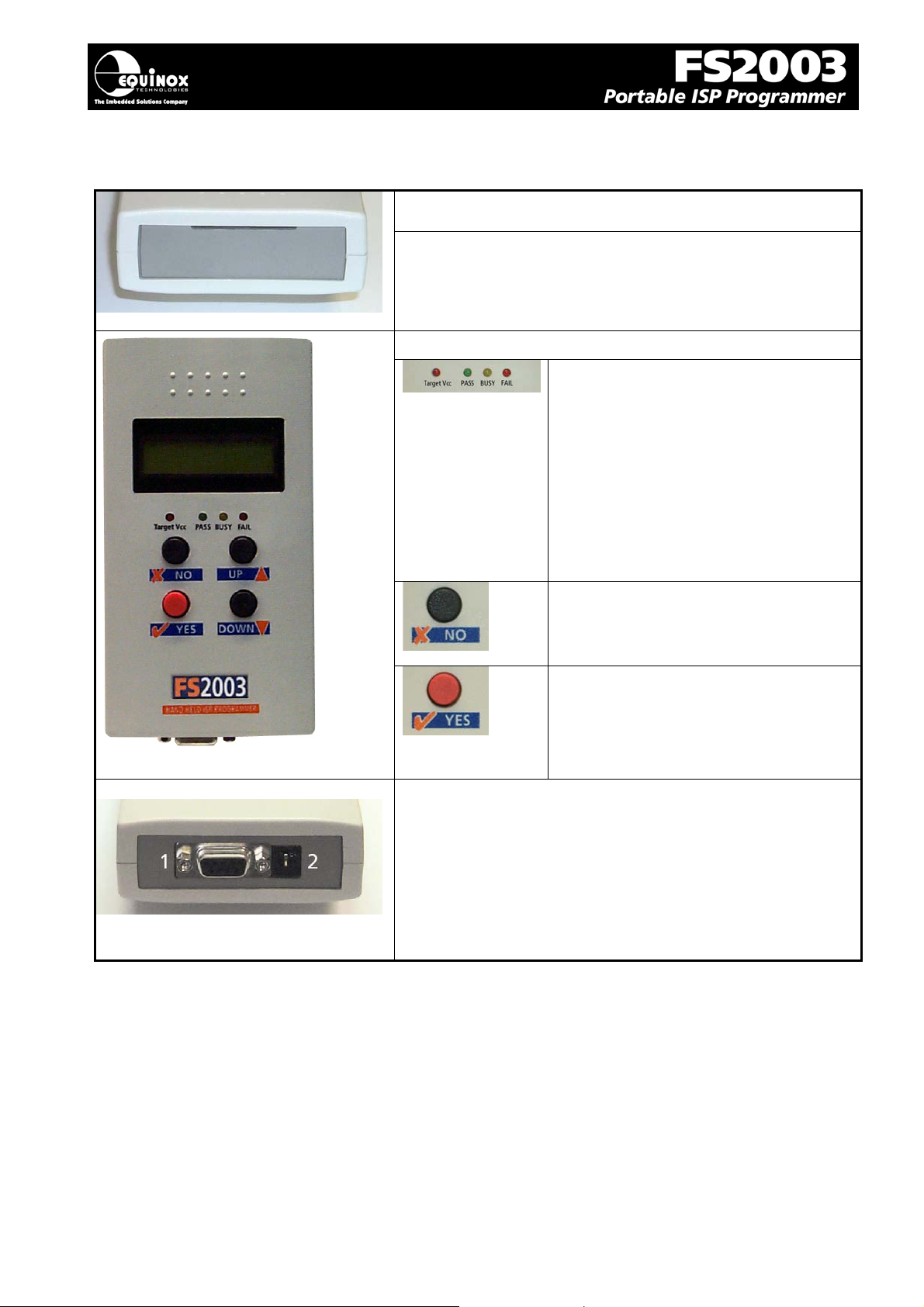
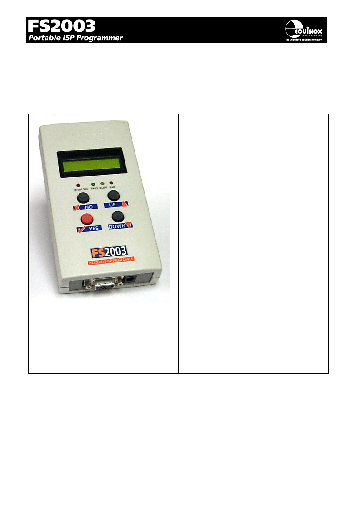
1.2 Hardware Overview (external layout)
Top Panel
ISP Cable Slot
ISP cable plugs into relevant ISP Header internally and
then exits the case through this slot.
Front Panel
<Target Vcc> LED
- Indicates when ‘Target Vcc’ is ON
- Does not indicate ‘Programmer
Power’ unless Jumper J9 is fitted.
Status LED’s:
<PASS> LED
<BUSY> LED
<FAIL> LED
<NO> Button
- Used to cancel a programming
Bottom Panel
1. RS-232 port (J5)
2. External DC Power Supply Input (CON1)
operation.
<YES> Button
- Used to start an ‘autoprogram’
operation.
FS2003 ISP Programmer - User Guide V1.07 – 1st September 2007 11
Page 15
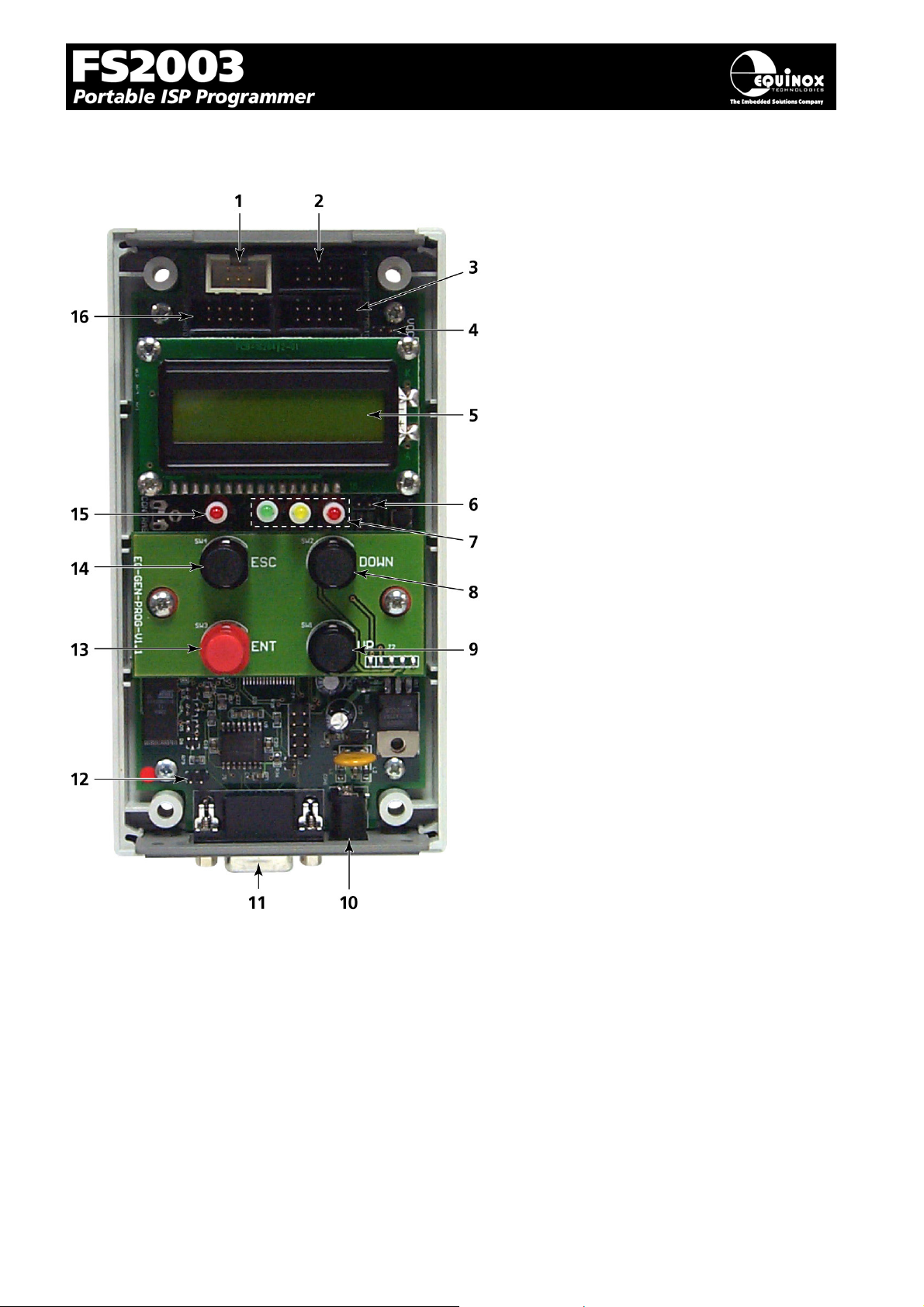
1.3 Hardware Overview (internal layout)
Hardware
1. Atmel 6-way ISP (SPI) Header (J3)
2. Equinox 10-way ISP (SPI / UART)
Header (J6)
3. Atmel 10-way ISP (SPI) Header
(J7)
4. Jumper (J9) – Vcc Link
5. Liquid Crystal Display (LCD)
6. Enable LCD Backlight Jumper
(J10)
7. Status LED’s
8. <Down> Key
9. <Up> Key
10. External DC Power Supply Input
(CON1)
11. RS-232 port (J5)
12. Firmware Update Jumper 2 (J11)
13. <YES> Key
14. <No> Key
15. Target Vcc Present – LED
16. Atmel 10-way JTAG Header
FS2003 ISP Programmer - User Guide V1.07 – 1st September 2007 12
Page 16
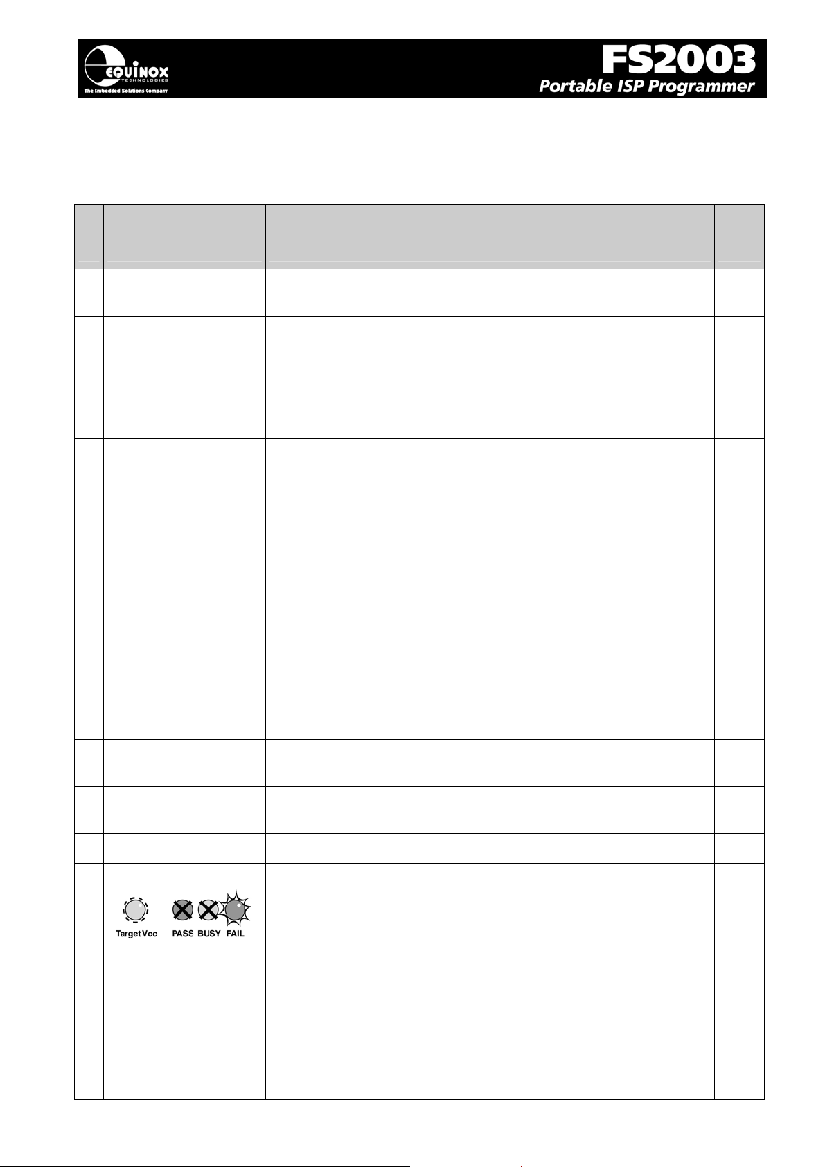
1.4 Programmer Specifications Overview
The table below details the hardware specifications for the programmer. Please refer to the stated
section for further information about any specific parameter.
#
Parameter
Description / comment
Refer
to
sect
1 Target Device
Support
2 Target Device
Programming
Interfaces
3 Operating modes
See Device Support List 1.5.1
The programmer supports the following programming interfaces:
• Atmel Low Voltage SPI
• Atmel High Voltage SPI (+12V Vpp)
• Atmel AVR JTAG (chargeable update)
• Atmel (formerly Temic) 8051 Boot loader ISP
• Philips (NXP) 8051 - Boot Loader ISP
The programmer supports the following operating modes:
As standard:
• Development Mode (PC controlled)
• Project Upload Mode using Upload Wizard (PC
controlled)
• Standalone Mode - Keypad + LCD operation
• Standalone Mode – Run Target
• ConsoleEDS EVAL – Command Line control
Optional chargeable upgrades:
• Standalone Mode - Remote Controlled via ‘ASCII Text
Communications’ RS-232 Serial Protocol
• PC controlled via ISP-PRO software (chargeable
upgrade)
• ConsoleEDS PRO – Command Line control
1.5.2
3.4
4 On-board FLASH
Memory Store
5 Project storage in
Memory Store
6 Keypad entry
7 Status LED’s
8 Programmer Display
9 Target Vcc
FS2003 ISP Programmer - User Guide V1.07 – 1st September 2007 13
32 Mbits (4 MBytes) FLASH Memory
64 x Independent Programming Projects
4 x Push Button - <YES>, <NO>, <UP>, <Down>
3 x Status LED’s located on the programmer:
<PASS>, <BUSY>, <FAIL>
These LED’s indicate the current status of the programmer.
2 x 16 character Back-lit LCD (backlight configurable)
• Target Vcc LED will illuminate when Target Vcc voltage is
Page 17
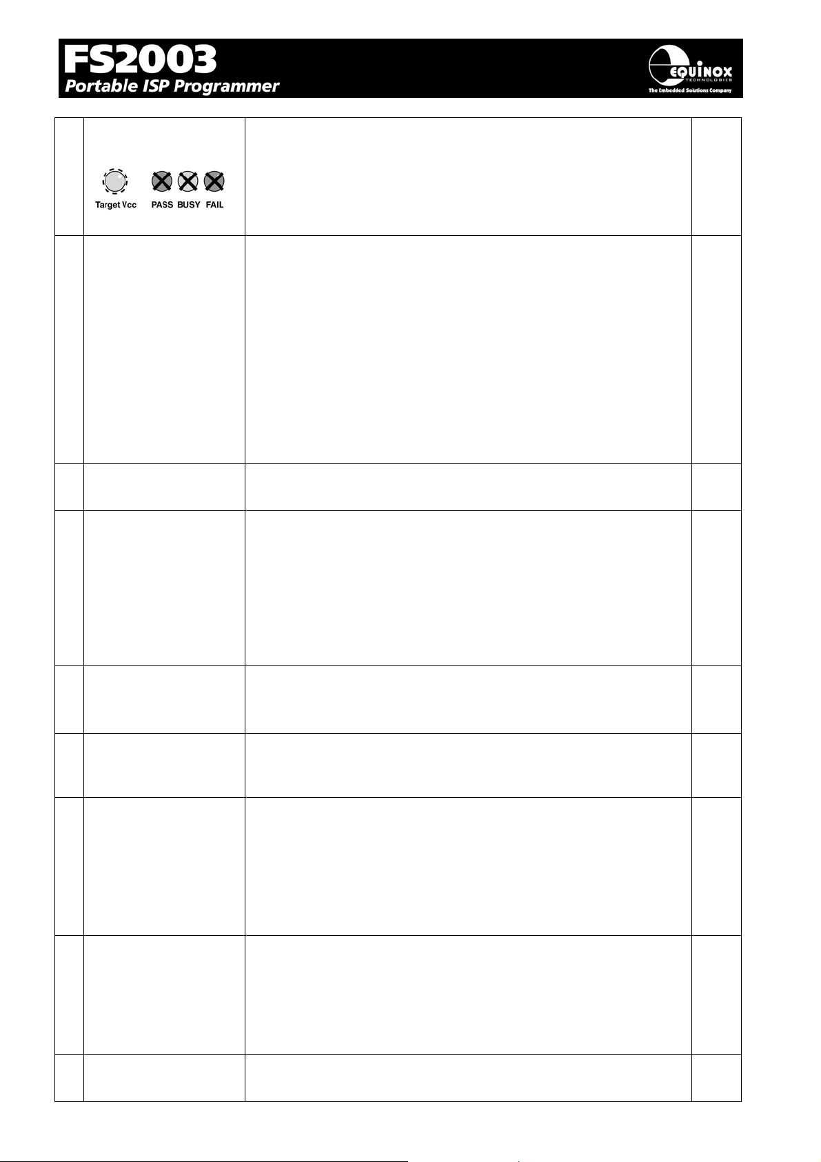
Voltage Detection
LED
10 PC Control Software
11 EQTools / ISP-PRO
PC requirements
12 Power Supply
Options
detected.
• Threshold detection voltage: approx 3.1V
The programmer can be controlled using:
As standard:
• EQTools
• Upload Wizard (integrated with EQTools)
• ConsoleEDS EVAL – Command Line control
Optional chargeable upgrades:
• ASCII Text Communications Mode
• ISP-PRO
• Standalone Upload Wizard
• ConsoleEDS PRO – Command Line control
PC running Windows 95 / 98 / 2000 / ME / NT4 / XP
There are 3 possible modes for powering the Programmer /
Target System:
• Programmer is powered from the Target System (3.0 –
5.0V)
• Programmer powers the Target System (+5.0V only)
• Programmer and Target System are independently
powered (Programmer at 9.0 -12V, Target System at 3.0
– 5.0V)
3.1
2.3
13 Voltage range
14 Vpp Voltage
Generator
15 DC Power Connector
(jack socket)
16 Target Voltage
measurement
17 Max. current through
programmer
• Device Programming voltage range: 3.0 – 5.0V
• Programmer Internal Vcc Voltage: 5.0V
• Possible Target System voltage range: 3.0 – 5.0V
On Board +12.0V Vpp Voltage Generator
(Applies +12.0V to RESET pin for Atmel ATtiny HV
programming)
DC Power Connector
• 2.5 mm Jack Socket – Centre Positive
• 9.0 – 12.0V DC regulated @ 500mA (worst case)
• Mates with Power Supply Adaptor supplied with
programmer
• DC Power Lead also supplied with programmer if a
customer power supply is to be used.
• The programmer can measure the Target Voltage in
either EDS or Standalone Mode.
• Measurement Voltage range: 3.0 – 5.0
Tolerance: +/-3%
This refers to the maximum current which the programmer can
supply from the internal Vcc rail
FS2003 ISP Programmer - User Guide V1.07 – 1st September 2007 14
Page 18
5
Max current = 300 mA.
18 Target SPI
Frequency
19 Target JTAG
Frequency
20 Target UART Speed
21 ISP Headers
The programmer supports three SPI speeds:
• SLOW SPI: 0 – 490.2 kHz (user selectable)
• MEDIUM SPI: 0 – 490.2 kHz (user selectable)
• FAST SPI: Disabled
( SPI speeds are estimations only due to uneven mark/space
ratio and non-continuous waveforms)
The programmer supports a user-defined JTAG frequency:
• SLOW: 0 – 833 kHz
• This is the Communications Speed (BAUD rate) from the
programmer to the Target Device when communicating
via a Boot Loader.
• The BAUD rate is configurable from 1,200 to 115 kBaud.
• This settings is completely independent from the BAUD
rate settings for the PC communicating with the
programmer.
The programmer support all the popular ISP Header as standard:
• Atmel 10-way (SPI)
• Atmel 6-way (SPI)
• Atmel 10-way (JTAG)
• Equinox 10-way (SPI+UART)
4.0
22 Frequency generator
output (SCK2)
23 Target Run
The FS2003 is capable of outputting a continuous square wave
at various frequencies on the programmer SCK2 pin.
The following pre-set frequencies can be selected via the
EQTools Programming Project:
1.8432 MHz, 921.6 kHz, 614.4 kHz, 460.9 kHz, 386.6 kHz, 307.6
kHz, 230.4 kHz,167.6 kHz, 102.4 kHz, 51.2 kHz
This clock frequency could be used for the following purposes:
• To toggle the STROBE pin on a Watchdog Timer IC to
stop the IC from timing out during the In-System
Programming operation.
• To provide a clock to an Atmel ATmega microcontroller to
resurrect a device which has an incorrectly configured
Internal Oscillator.
Please refer to the ‘EQTools – Getting Started Guide’ for full
details of setting up the SCK2 oscillator.
The programmer is capable of automatically running firmware
which has been programmed into a Target Device and waiting
until the MISO pin is asserted by the Target Device.
24 Pre-Programming
State Machine
The programmer has 5-state ‘Pre-programming State Machine’
which allows the I/O lines of the programmer to be sequenced in
order to place the Target Device into Serial Programming Mode.
25 PC Connection RS232 – Single Programmer Channel Control
1.8
• 9-way Female D Connector
FS2003 ISP Programmer - User Guide V1.07 – 1st September 2007 1
Page 19

• Connects to spare PC COM port
• All 9 connections must be made in serial cable.
• Baud rate: 38,400 (fixed)
26 Temperature range
27 Dimensions
28 Shipped Weight
0 to 50 deg. C
189H x 80L x 31D mm
0.75 kg
FS2003 ISP Programmer - User Guide V1.07 – 1st September 2007 16
Page 20
7
1.5 Device Support
1.5.1 Devices supported by the programmer
The programmer supports the following devices (at the time of this manual going to press):
# Silicon
vendor
Family Programming
algorithm
Device support
1 Atmel
2 Atmel
3 Atmel
4 Atmel
5 Atmel
6 Atmel
7 Atmel
AT89S LV SPI - AT89(L)S8252/53
- AT89(L)S51/52
(including ‘L’ versions)
- AT89S 2051 / 4051
- AT89S8253
AT90S (AVR) LV SPI - AT90(L)S1200(A) / 2313 / 2333 / 4433 / 2323
/ 2343 / 4414 / 8515 / 4434 / 8535
(including ‘L’ versions)
AT90CAN LV SPI AT90CAN128 / AT90CAN64 / AT90CAN32 S
AT90CAN JTAG (AVR) AT90CAN128 / AT90CAN64 / AT90CAN32 U
AT90USB LV SPI AT90USB1286/ AT90USB1287/
AT90USB162/ AT90USB646/ AT90USB647/
AT90USB82
AT90USB JTAG (AVR) AT90USB1286, AT90USB1287,
AT90USB646, AT90USB647
ATmega (AVR) LV SPI - ATmega 8 / 16 / 32 / 48 / 88 / 64 / 103 / 128 /
1280 / 1281 / 168 / 169(V) / 169PV / 323 / 325
/ 329 / 2560 / 2561 2561V / 8515 / 8535
(including ‘L’ versions)
S
S
S
U
S
8 Atmel
9 Atmel
10 Atmel
11 Atmel
(Temic)
12 NXP
(Philips)
13 Zensys
ATmega
(AVR)
ATtiny (AVR) LV SPI ATtiny 12 / 13 / 15L / 22 / 24*/ 25 / 26 / 45 / 85
ATtiny (AVR) HV SPI (+12V
T89C51Rx2 UART Boot
T89C51Rx2 UART Boot
ZW series LV SPI ZW0102 / ZW0201 / ZW0301 S
JTAG (AVR) ATmega 8515 / 8535 / 32 / 64 / 128 / 1280 /
1281 / 161 / 162 / 163 / 169 / 323 / 325 / 329 /
3290(V) 406 / 640(V) / 2560 / 2561
(including ‘L’ versions)
/ 2313
(including ‘L’ versions)
ATtiny 11 / 12 / 15L
VPP)
Loader
Loader
(including ‘L’ versions – Vcc must be +5V with
a +12V Vpp applied to the RESET pin)
HV ISP support for the ATtiny13, 25, 45 etc is
not currently available.
T89C51 RB2 / RC2 / RD2
T89C51 IB2 / IC2
T89C51CC01
(Support for the AT89Cxxxx devices is not
currently available)
P89C51 RB2 / RC2 / RD2
P89C 660 / 662 / 664 / 668
U
S
S
S
S
FS2003 ISP Programmer - User Guide V1.07 – 1st September 2007 1
Page 21
Key:
S – Device supported as standard
U – Chargeable license upgrade required
* – Support to be announced – please contact Equinox for a Support Date
For an up-to-date Device Support list, please refer to the ‘Device Support’ section for this programmer
on the Equinox Website.
Important note:
Please refer to the relevant Application Note for details of how to connect the programmer to the
Target Device on the Target System. The Application Notes can be found on the FS2003 Download Page on the Equinox website.
1.5.2 Programming Interface to Target Device
¾ The programmer supports the following programming interfaces to the Target Device:
# Programming
Interface
1 LV SPI
2 HV SPI (+12V
Vpp)
3 UART Boot
Loader
Family Description / Comment
AT89S
AT90S
AT90USB
AT90CAN
ATmega
ATtiny
Zensys
ATtiny
T89C51Rx2
P89X51Rx2
Atmel Low Voltage Serial Programming Mode
• Atmel 3-wire SPI interface (SCK, MOSI, MISO )
• Target Device RESET
• Works at target voltage (no Vpp required)
Atmel High Voltage Serial Programming Mode
• Atmel 4-wire SPI Interface (SCK, MOSI, MISO, MOSI2)
• +12V Vpp is applied to the RESET pin to enter High
Voltage Serial Programming Mode
• Requires different connections to Target Device
compared with LV SPI.
• Requires all pins of target device to be accessible by the
programmer.
Atmel / Philips UART Boot Loader Interface
• Uses RXD, TXD, PSEN, and Target Device RESET pin
• TTL Levels from programmer to Target System
4 JTAG
(Atmel AVR)
Please note:
A chargeable license upgrade is required to enable the ATmega JTAG ISP libraries.
ATmega
AT90USB
AT90CAN
Atmel ATmega AVR – JTAG ISP Interface
• Uses same connector as Atmel JTAG ICE
• A chargeable license upgrade is required to enable the
ATmega JTAG ISP libraries.
FS2003 ISP Programmer - User Guide V1.07 – 1st September 2007 18
Page 22
1.6 DC Power Input Connector (CON1)
It is possible to power the programmer from an external power supply by plugging the DC Power
Cable supplied with the programmer into CON1. This connector is a 2.5mm jack socket.
Fig. 1.6.1 CON1 – pin-out
Description Voltage
Centre pin +9.0V to +12.0V from external power supply
Outer 0V (Ground connection)
1.7 DC Power Cable Specification
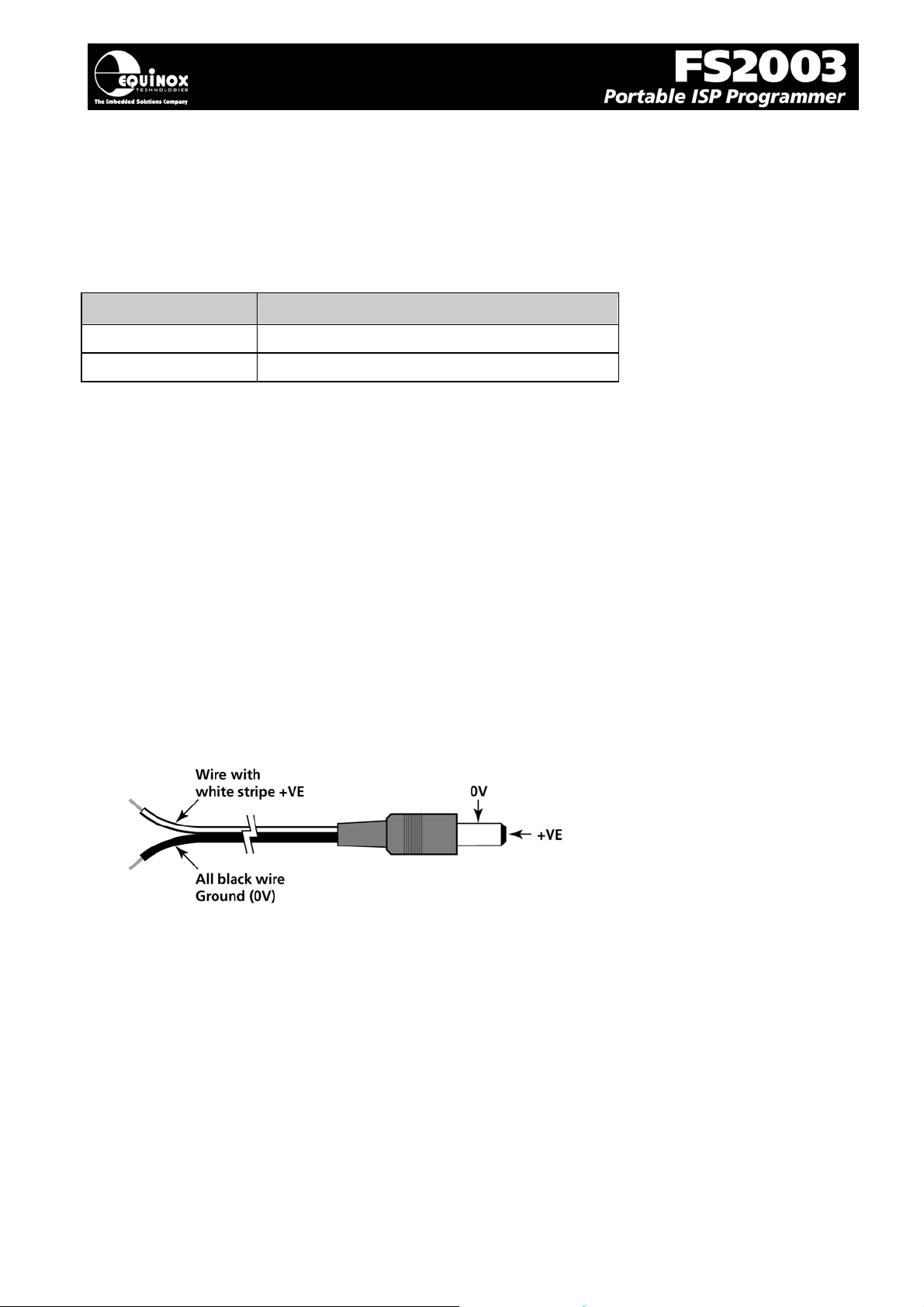
¾ The programmer is supplied with a DC power cable which plugs into CON1. The other end of
this cable is supplied with bare wire ends for connecting to an external power supply e.g.
bench PSU.
Cable Specification:
• One end features a female 2.5mm DC jack plug
• The other end of the cable is supplied with bare wire ends for connecting to an external power
supply e.g. bench PSU.
• The black lead with the white stripe is the +VE cable.
• The all black lead is the GROUND cable.
• The external voltage applied to CON1 must be between 9.0 and 12.0V!
FS2003 ISP Programmer - User Guide V1.07 – 1st September 2007 19
Page 23
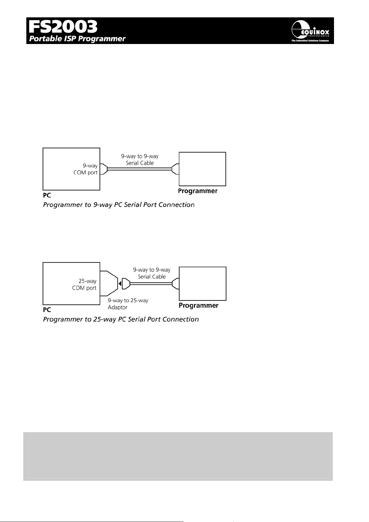
1.8 J5 – RS-232 Communications Port & Serial Cables
1.8.1 Connecting the programmer to the PC COM port
The programmer communicates with a PC via the RS-232 Communications Port (J5). A suitable 9way to 9-way serial cable is supplied with the programmer.
The programmer is supplied with the following PC Serial Cables / Adaptors:
1. 9-way D (female) to 9-way D (Male) Serial Cable
This cable should be connected between the 9-way D-connector on the programmer and a spare 9way RS-232 COM port on your PC.
2. 9-way D (female) to 25-way D (Female) adaptor
If your PC has a 25-way D connector, you will need to plug the 9-25 way adapter onto the end of the
9-9 way Serial Cable as shown in the diagram below.
1.8.2 Serial Cable Length
The serial cable supplied with the programmer is approximately 2m in length. If you wish to make your
own longer cable, please ensure that you connect all 9 pins at each end in a straight-through pin-topin fashion. See fig. 1.7.3 for the pin-out specifications. The programmer features an ESD protected
full RS-232 specification driver chipset and so should operate reliably when driving serial cables up to
10m in length. However, it is recommended to keep the serial cable as short as possible to enhance
EMI immunity and reduce EMI emissions.
Important note:
The programmer uses ALL of the NINE pins of the COM port for different purposes. It is therefore
imperative that the cable used to connect between the programmer and the PC COM port has all
NINE cables connected. Failure to do this will result in the programmer not operating correctly.
FS2003 ISP Programmer - User Guide V1.07 – 1st September 2007 20
Page 24
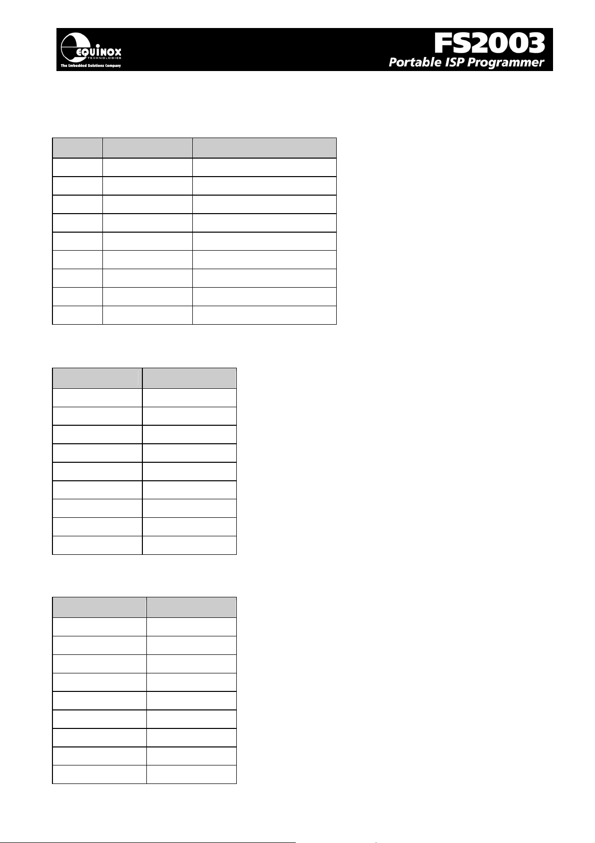
1.8.3 Serial Cable Pin-outs
Fig. 1.8.3.1 Pin-out of J5 - RS-232 Communications Port
Pin No. RS232 pin Description
1 DCD Not Connected
2 RXD Receive
3 TXD Transmit
4 DTR Not Connected
5 0 Volt 0V
6 DSR Not Connected
7 RTS Not Connected
8 CTS Not Connected
9 RING Not Connected
Fig. 1.8.3.2 Connections for 9-way to 9-way Serial Cable (Straight through cable)
9-way (Male) 9-way (Female)
1 1
2 2
3 3
4 4
5 5
6 6
7 7
8 8
9 9
Fig. 1.8.3.3 Connections for 9-way to 25-way Adaptor
25-way (Female) 9-way (Male)
8 1
3 2
2 3
20 4
7 5
6 6
4 7
5 8
22 9
FS2003 ISP Programmer - User Guide V1.07 – 1st September 2007 21
Page 25
2.0 Hardware Installation
2.1 Overview
This section details how to set up the programmer hardware including Power Supply, Earthing
Requirements, PC Serial Port Connection and ISP Header Selection.
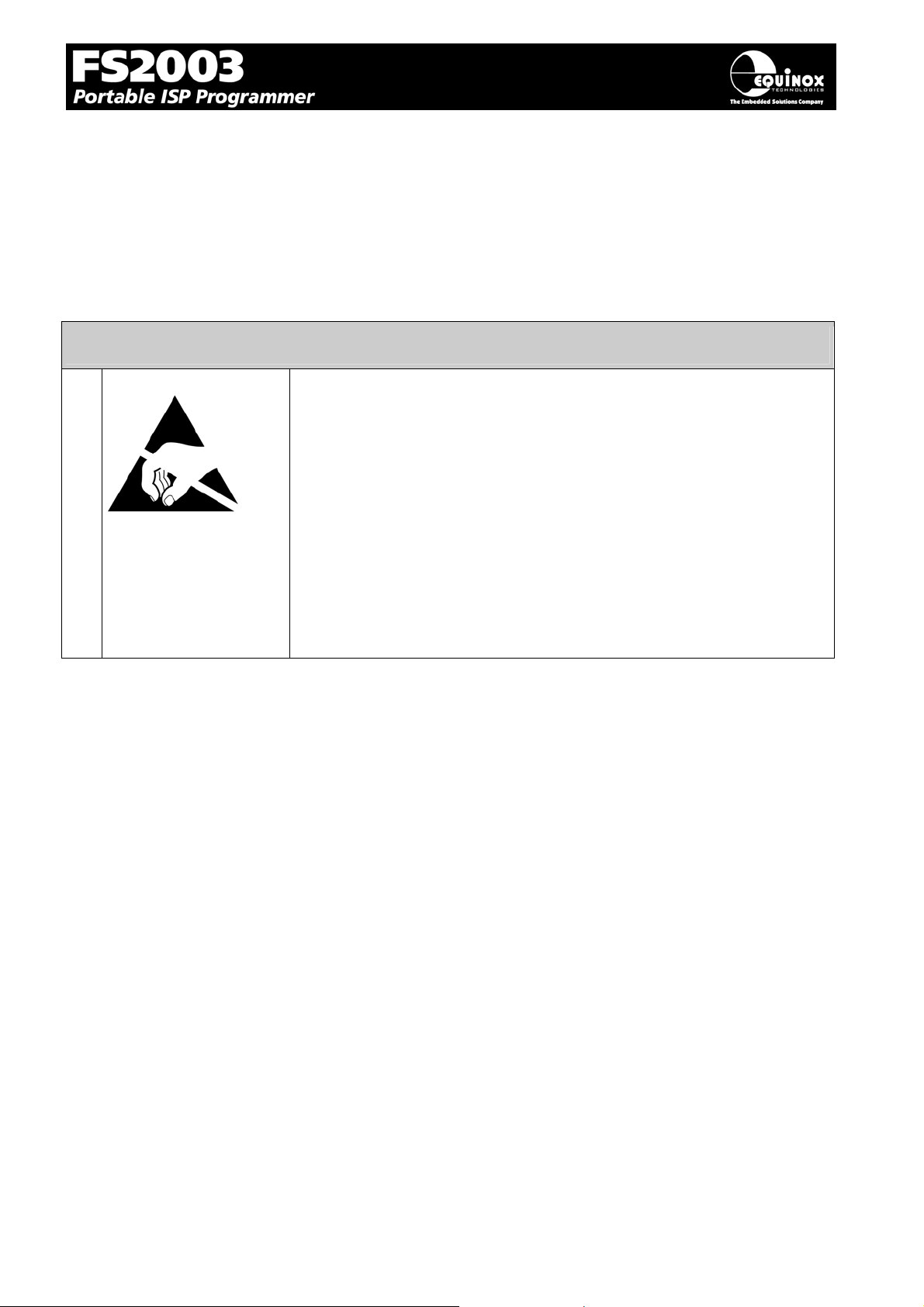
2.2 ESD Precautions
• Work in a static-free environment.
• Wear an earthed wrist strap when handling either the programmer
and/or any programmable device.
• Ensure that the PC, programmer and Target system are connected
to the same EARTH (0V) potential.
• Do NOT plug the ISP cable of the programmer into a Target
System when the Target power is ON.
• The programmer I/O lines are ESD protected, but it always good
practice to take proper ESD precautions. This can help to avoid
ESD damage to either the programmer or Target System.
FS2003 ISP Programmer - User Guide V1.07 – 1st September 2007 22
Page 26
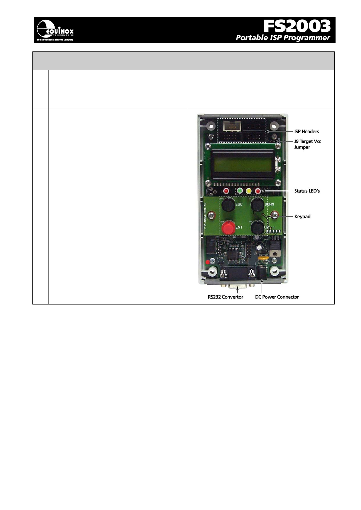
2.3 Removing the programmer cover
Remove programmer from all packaging and
a
place display-side down on a flat surface
Remove all four screws from the back of the
b
programmer (if fitted)
Remove programmer cover to reveal internal
c
electronics
The screws will be supplied in a separate small
plastic bag if this is a new programmer.
FS2003 ISP Programmer - User Guide V1.07 – 1st September 2007 23
Page 27
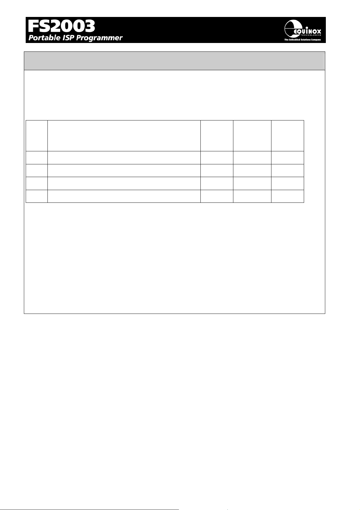
2.4 Powering the Programmer / Target System
2.4.1 Select the required method of powering the Programmer / Target
System
The programmer supports the following power supply methods:
Sect Power Supply method Jumper
J9
2.4.2
2.4.3
2.4.4
2.4.5
Powering the Target System at +5.0V from the programmer
(external mains power supply adaptor)
Powering the Target System at +5.0V from the programmer
(external bench power supply)
Powering the programmer from the Target System at 3.0 –
5.0V
Programmer and Target System are Independently powered
FITTED 5.0V from
FITTED 5.0V from
FITTED 3.0 – 5.0
NOT
FITTED
Refer to fig.2.3.1 for a diagram showing the power supply methods of the FS2003 programmer.
Please choose the relevant powering method from the table above and then refer to the relevant
section 3b, 3c, 3d, 3e below.
Key:
• Target Vcc – This is the voltage of the Target System
• CON1 Jack Socket – This is the DC Jack socket on the bottom of the programmer.
• Programmer Vcc – This is the +5.0V supply which powers all the internal electronics of the
programmer.
• Jumper J9 – This jumper connects the ‘Programmer Vcc (+5V)’ supply to the ‘Target Vcc’
supply. This jumper can be found next to the COM port inside the programmer.
Target
Vcc (V)
CON1
Jack
Socket
(V)
9.0V
programmer
9.0V
programmer
Do NOT
connect
3.0 – 5.0 9.0V
FS2003 ISP Programmer - User Guide V1.07 – 1st September 2007 24
Page 28
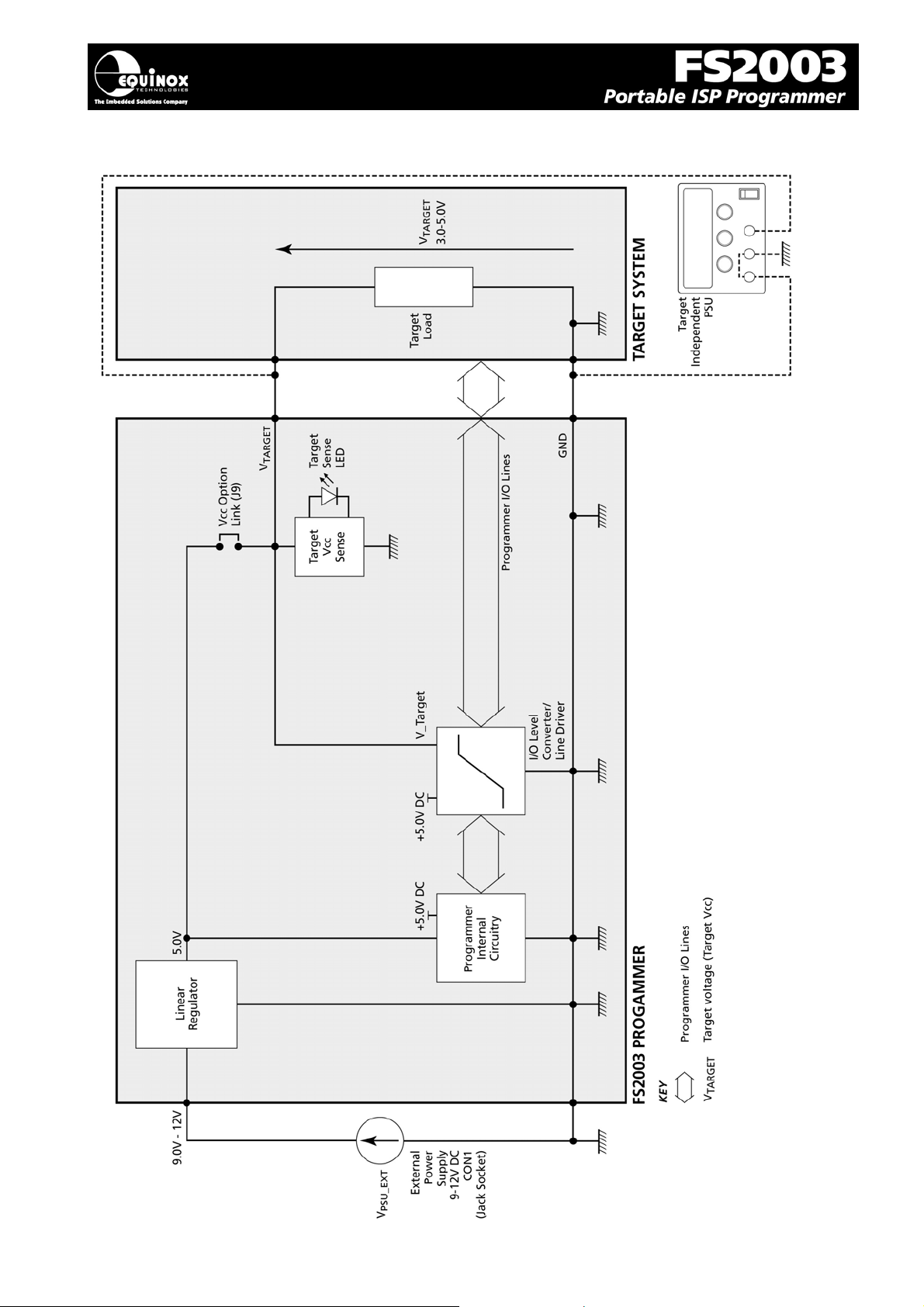
5
Fig. 2.4.1 FS2003 – Power Supply Overview Schematic
FS2003 ISP Programmer - User Guide V1.07 – 1st September 2007 2
Page 29
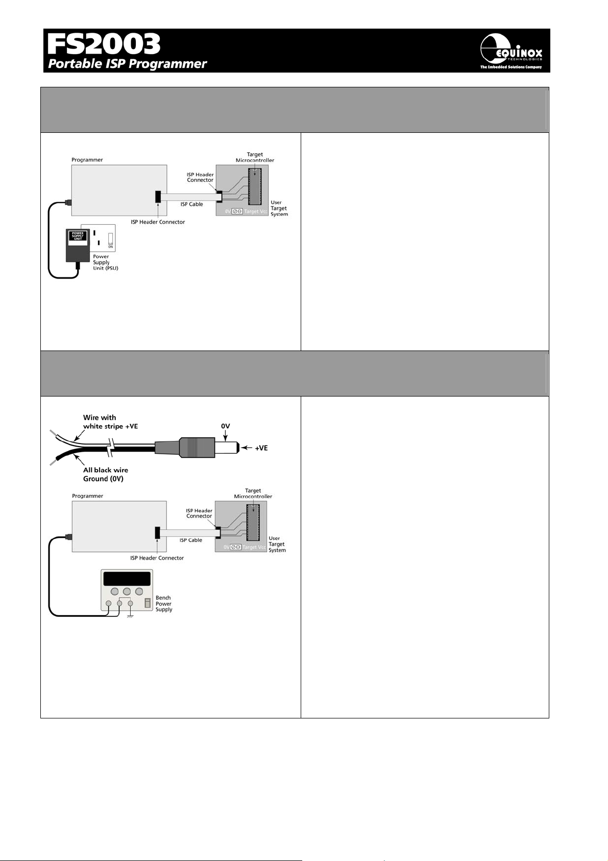
2.4.2 Powering the Target System at +5.0V from the programmer (external
mains power supply adaptor)
• Plug power supply jack into mating jack
socket CON 1 on the rear of the
programmer.
• External power supply must be 9.0 to
12.0V DC regulated (9.0V DC regulated
power supply is supplied with the
programmer).
• Fit the Jumper J9 which connects the
programmer +5.0V Vcc supply to the
Target Vcc on the ISP Header
connectors.
• Plug the mains adaptor into the mains
supply but do not switch the power on.
2.4.3. Powering the Target System at +5.0V from the programmer
(external bench power supply)
• The programmer is supplied with a DC
power cable with a jack plug on one end
and bare wires at the other end.
• Plug the jack plug into the mating jack
socket CON 1 on the programmer.
• Connect the bare wire ends to a suitable
external power supply e.g. bench power
supply.
• The wire with the WHITE STRIPE on it is
+VE and the all black wire is –VE
(GROUND).
• The external power supply must be 9.0
to 12.0V DC regulated
• Fit the Jumper J9 which connects the
programmer +5.0V Vcc supply to the
Target Vcc on the ISP Header
connectors.
• If you have a ‘Current Limit’ setting on
your Power Supply, set it to the minimum
value to start with and then increase it
until the programmer powers up without
tripping the Current Limit.
FS2003 ISP Programmer - User Guide V1.07 – 1st September 2007 26
Page 30
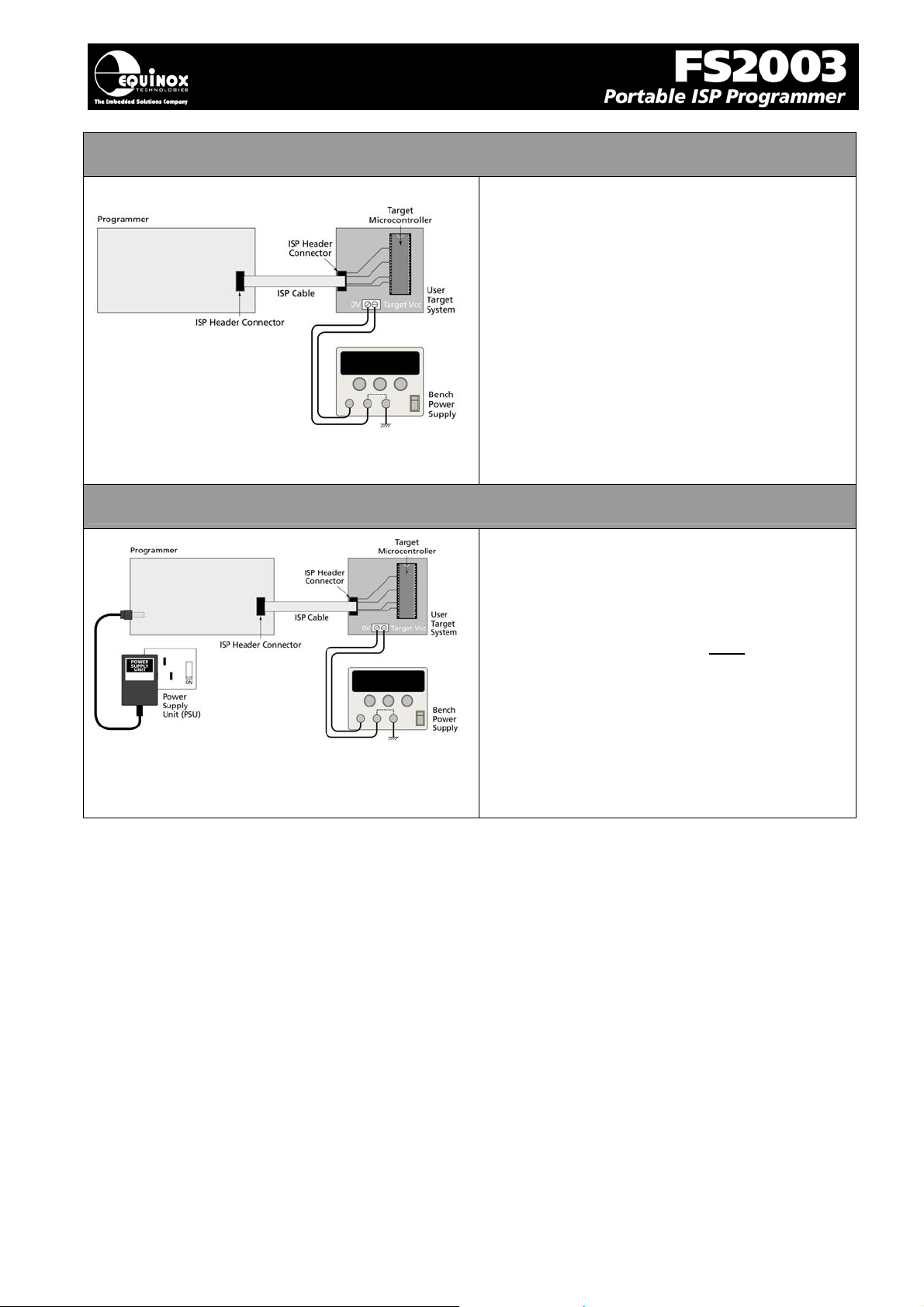
7
2.4.4 Powering the programmer from the Target System at 3.0 – 5.0V
• The Target System can supply power to
the programmer as long as the Target
Voltage is 3.0 – 5.0V.
• The Target System must be able to
supply the worst case programming
current to the programmer (approx
60mA).
• Fit the Jumper J9 which connects the
Target Vcc (3.0 – 5.0V) on the ISP
Header connectors to the Programmer
Vcc rail.
• The programmer will automatically boost
the Target Vcc supply up to +5.0V if it is
less than 5.0V.
2.4.5 Programmer and Target System are Independently powered
• The programmer is powered from +9.0 to
12.0V via the DC power input (CON1) on
the rear panel of the programmer.
• The Target System is powered from an
independent power supply.
• The Jumper J9 must NOT
This disconnects the Target Vcc from the
Programmer +5V Vcc.
• The ‘Target Vcc’ signal must still be
connected to the ‘Programmer Vcc’
signal on the ISP Header as this voltage
is used to power the ‘I/O Level
Convertor’.
be fitted.
FS2003 ISP Programmer - User Guide V1.07 – 1st September 2007 2
Page 31
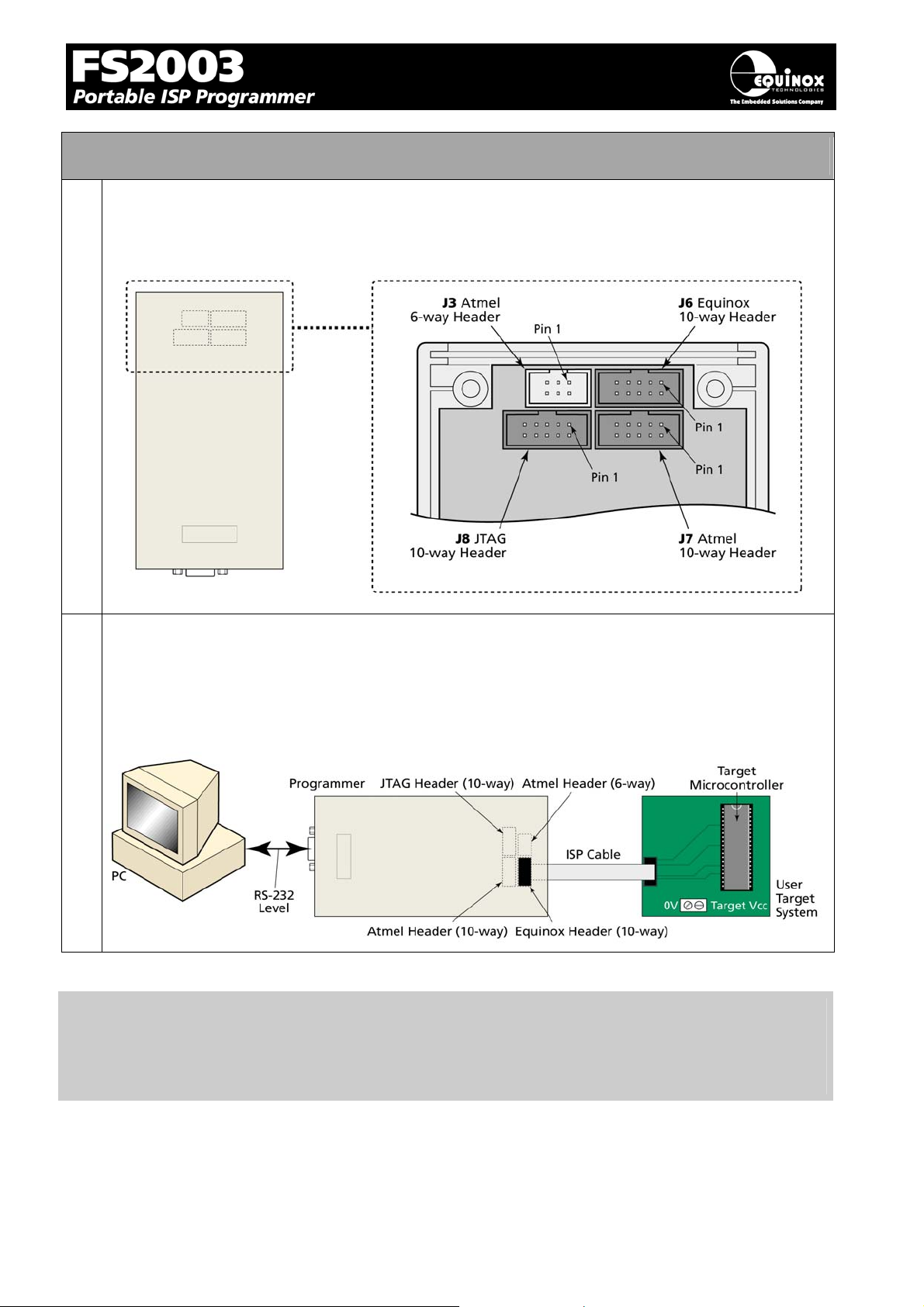
2.5 Selecting the correct ISP (In System Programming) Header
a Select the required ISP Header and then plug the ISP Cable into this Header.
Please refer to section 4 of this manual for full details of all the available headers.
b Connect the ISP cable to the ISP Header on your Target System
Make sure the programmer and Target System Power is switched OFF !
Make sure that the ISP Cable plug is inserted the correct way around into the ISP Header on
the Target System.
Important note:
Please refer to the relevant Application Note for details of how to connect the programmer to the
Target Device on the Target System. The Application Notes can be found on the FS2003 Download Page on the Equinox website.
FS2003 ISP Programmer - User Guide V1.07 – 1st September 2007 28
Page 32
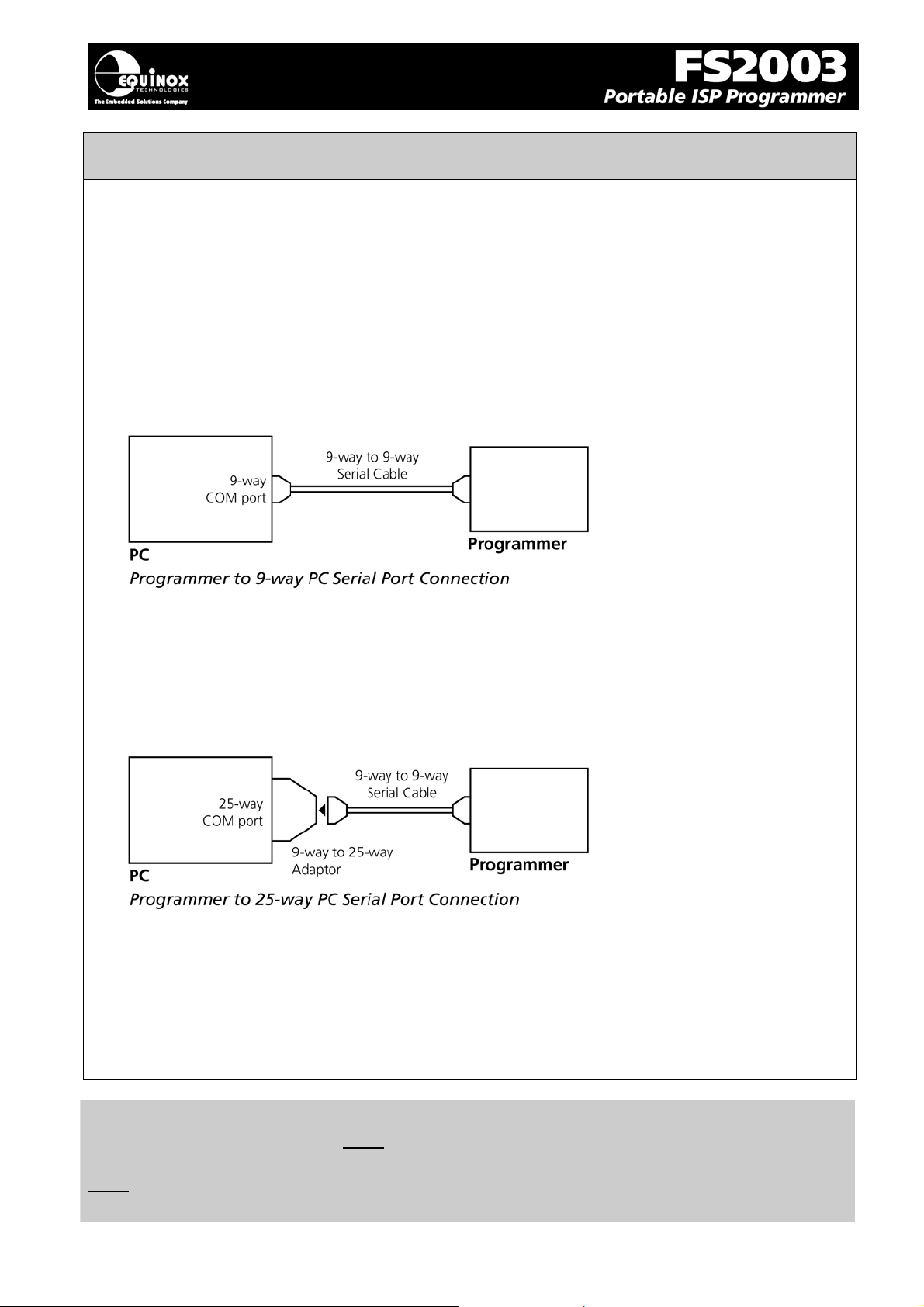
2.6 Connecting the programmer to the PC Serial (COM) Port
The programmer communicates with a PC via the RS-232 Communications Port (J5).
The programmer is supplied with the following PC Serial Cables / Adaptors:
• 9-way D (Female) to 9-way D (Male) Serial Cable
• 9-way to 25-way Serial Adaptor
2.6.1 9-way PC Serial Port Connection
The 9-way serial cable should be connected between the 9-way D-connector on the programmer and
a spare 9-way RS-232 COM port on your PC.
2.6.2 25-way PC Serial Port Connection
If your PC has a 25-way D connector, you will need to plug the 9-25 way adaptor onto the end of the
9-9 way Serial Cable as shown in the diagram below.
2.6.3 USB Connection
If your PC does not have a COM port, it will be necessary to use a ‘USB to RS232 Convertor Cable’.
You can purchase a suitable cable from most PC retailers. Equinox can also supply a suitable cable.
Important note:
The programmer uses ALL of the NINE pins of the COM port for different purposes. It is therefore
imperative that the cable used to connect between the programmer and the PC COM port has all
NINE cables connected. Failure to do this will result in the programmer not operating correctly.
FS2003 ISP Programmer - User Guide V1.07 – 1st September 2007 29
Page 33

2.7 Earthing requirements
2.7.1 Overview
When setting up the programmer to In-System Program (ISP) a device on a Target System, extreme
care must be taken to ensure that the 0V of the PC, programmer, Target System and any external
devices are at the same ‘earth potential’. If you are using the programmer with a laptop computer,
please read section 3.2.2 carefully.
ESD Points to remember
Failure to follow correct ESD procedures when using this product could lead to
damage to the programmer and/or the Target System.
• Wear an earthed wrist strap when handling either the programmer and/or
any programmable device.
• Ensure that the PC, programmer, Target System and any external devices
are all connected to the same GROUND potential.
2.7.2 Laptop earthing issues
The Problem:
Most laptops use an external double-insulated mains power supply which is not earthed to mains
earth. This means that the laptop earth is likely to be floating at some voltage other than 0V. If the
programmer is attached to the PC COM port with the PC powered ON and then the ISP lead is
plugged into an earthed Target System, then the PC GROUND will discharge through the COM port
GROUND, through the programmer into the Target System. This ESD may damage both the
programmer and the Target System !
The Solution
• Ensure that the laptop is powered OFF when connecting the ISP cable from the programmer
to an earthed Target system
• Use the programmer in Standalone Mode if possible (ie. not connected to a PC)
2.7.3 Desktop PC earthing issues
The Problem:
The chassis on desktop PC must be connected to mains earth to comply with Health and Safety
legislation. If the chassis is not earthed for some reason, the PC power supply GROUND will be
floating and it is then possible to discharge a high level of energy stored in the power supply mains
filter through the programmer into the Target System. This ESD may damage both the programmer
and the Target System !
The solution:
• Ensure that the PC chassis is properly earthed to mains earth.
• Connect an earthing bond wire from the PC chassis to the GROUND connection of either the
programmer or the Target system / Test Fixture.
FS2003 ISP Programmer - User Guide V1.07 – 1st September 2007 30
Page 34
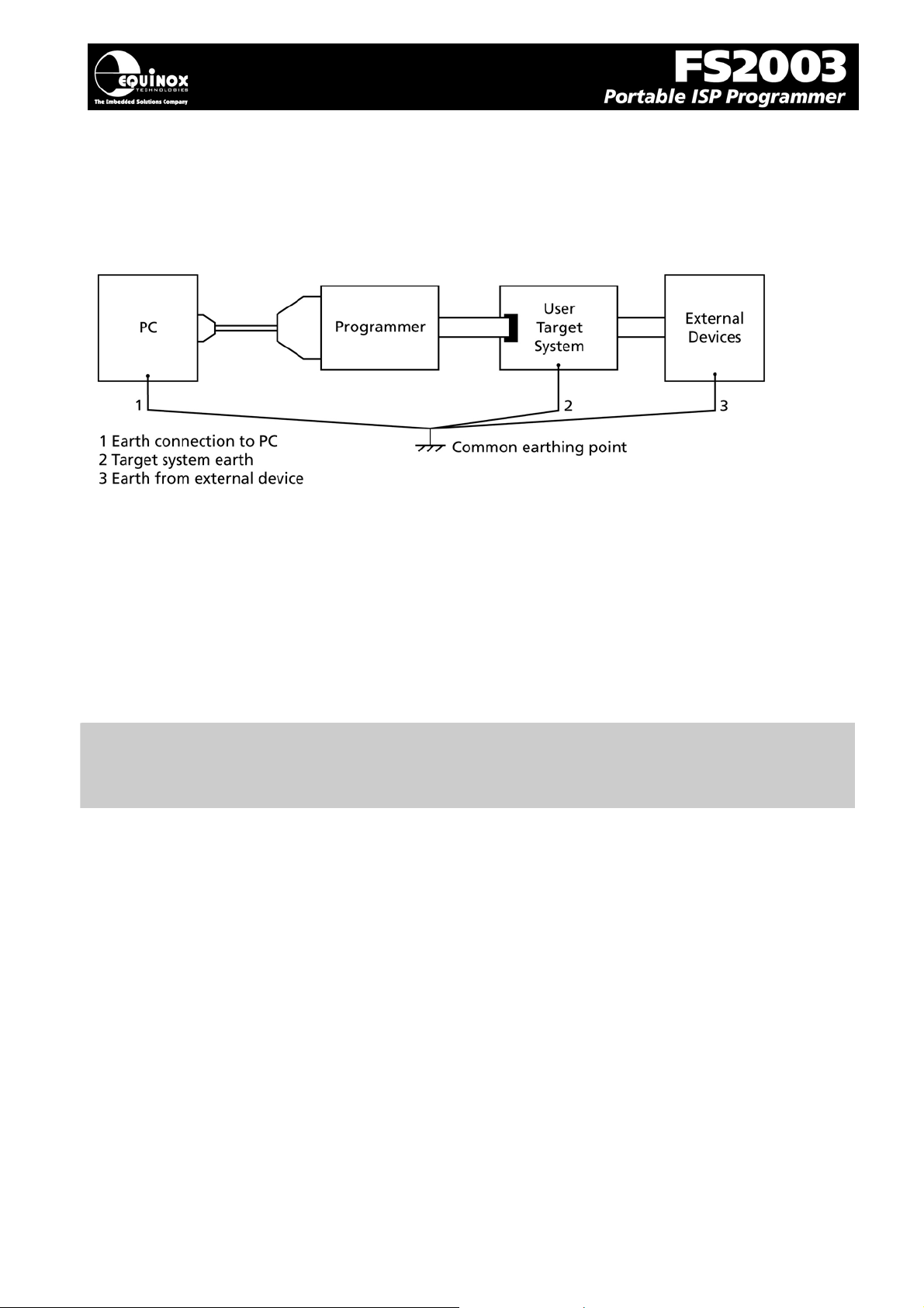
2.7.4 Earthing recommendations
To avoid catastrophic damage to PC, programmer or target system:
• Ensure that both your target system and PC are connected to a common earth point
• Make sure that all interconnections are made before applying power to PC and target system
• If you are using a laptop or PC which is not connected to mains earth, it is recommended that
you make a hard-wired connection from the COM port D-connector shell and the target system
to a common earth point
• Avoid plugging and unplugging ISP connector while either the PC or Target System is
powered up
• Please ensure that any devices connected to the user target system are also properly
grounded to the same common earth point
Warning!
Any damage caused to the programmer by Electrostatic Discharge (ESD) through inadequate
earthing is not covered under the warranty of the product.
FS2003 ISP Programmer - User Guide V1.07 – 1st September 2007 31
Page 35
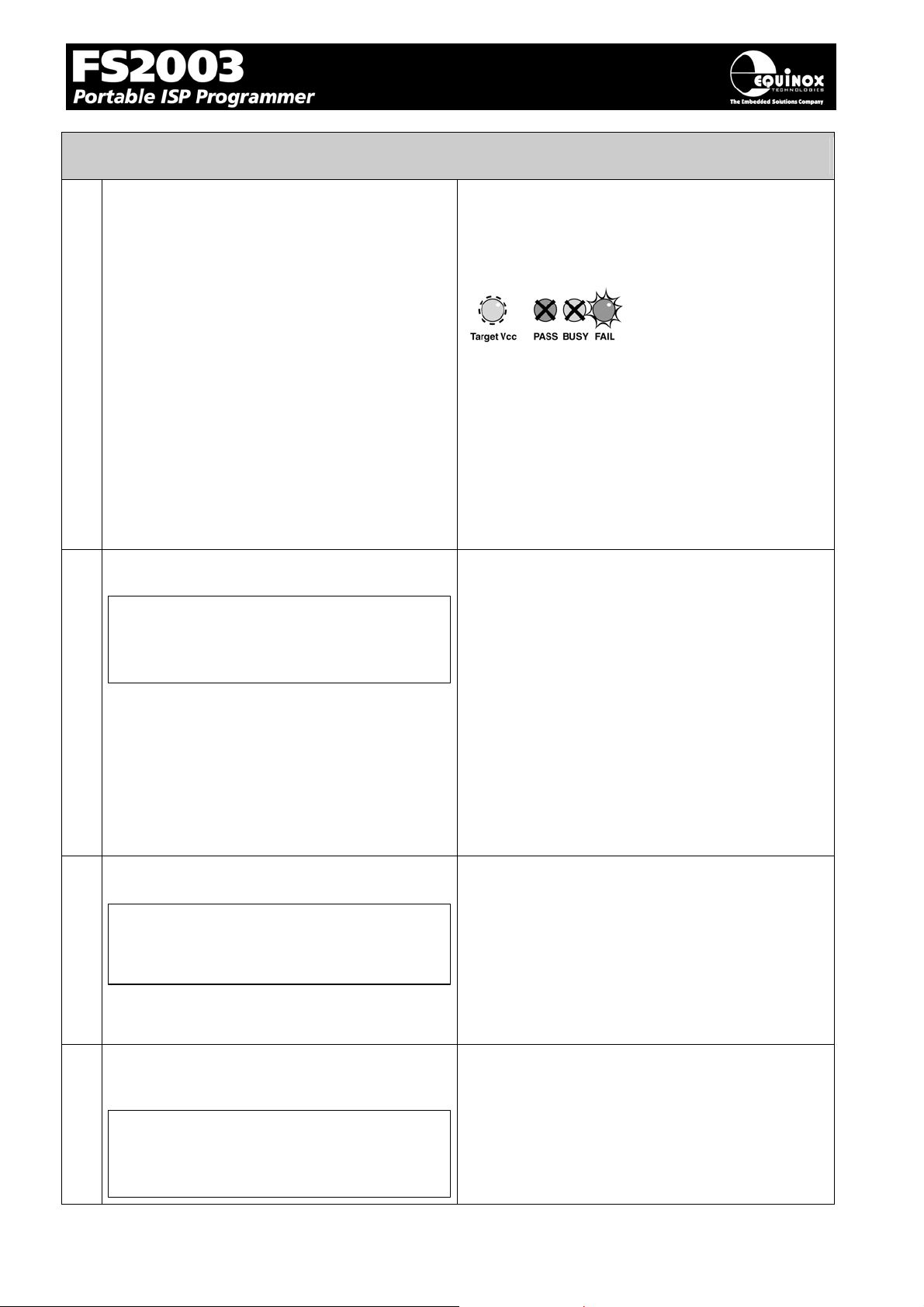
2.8 Testing the programmer hardware
a Apply power to the programmer
If you have a ‘Current Limit’ on your power
supply, turn it to approximately 20mA and
then gradually increase it until the
programmer ‘FAIL’ LED starts to FLASH.
b No Programming Projects Loaded
NO / INVALID
PROJECT LOADED!
Æ Programmer circuitry powers up to 5.0V.
Æ Target Vcc LED illuminates
The LED will illuminate if a target voltage
between 3.0 and 5.0V is detected.
Æ FAIL LED flashes to indicate that the
programmer has rebooted. *** The FAIL LED no
longer flashes with firmware version 2.46 or
greater)
Æ The programmer display now initialises to
show the programmer type, firmware version
etc. See 2.7(b), (c), (d).
• If the programmer has never been used
before or the on-board FLASH Memory
Store has been erased, then the
programmer will display the message:
‘No / Invalid Project Loaded’. This is
normal as the programmer ‘FLASH
Memory Store’ is empty so the
programmer cannot be used in
Standalone Mode.
• It is not possible to check the
programmer information until a valid
project is uploaded. Please upload a
valid project to the programmer using
EQTools and then try again.
c Check the programmer firmware version
EQUINOX-TECH UK
FS2003 Ver:2.41
d Check the programmer serial number,
build revision and build date
SN:619 1.01
DATE 19-1-2004
FS2003 ISP Programmer - User Guide V1.07 – 1st September 2007 32
• The programmer display now shows the
programmer type and the firmware
version.
e.g. 2.37.
• You can check that you have the very
latest firmware version by viewing the
‘Configit – Firmware Update Utility’ on
the Equinox website.
After 2 seconds the display will update to show
the following information:
• Serial Number (SN): eg. 619
• Hardware Build Version: eg. 1.01
• Build date: eg. 19 /1/2004
Page 36
2.9 Re-assembling the programmer
Re-fit lid to programmer
a
Re-fit the four screws in the back of the case
b
Ensure that the PC, programmer and Target
c
System power is switched OFF.
Please note:
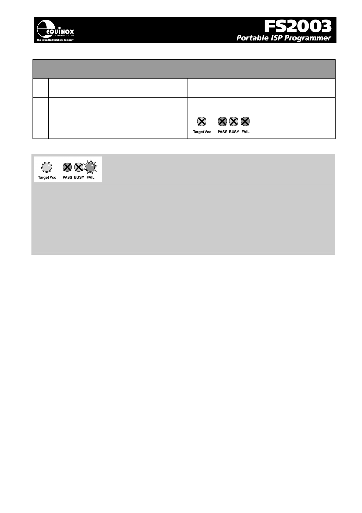
• The FAIL LED will flash when you initially power up the programmer if you are running
firmware 2.46 or below.
• If you are running firmware version 2.46 or greater the FAIL LED will no longer FLASH.
• To clear the FAIL LED condition, use the <Up> / <Down> keys to select a Programming
Project and then press the <Yes> key .
• If there are no Programming Projects Loaded into the Programmer – Flash Memory Store,
the FAIL LED will continue to FLASH until at least one Project is uploaded.
Hardware installation is now complete.
The ISP Cable should fit through the slot in the
end panel.
FS2003 ISP Programmer - User Guide V1.07 – 1st September 2007 33
Page 37
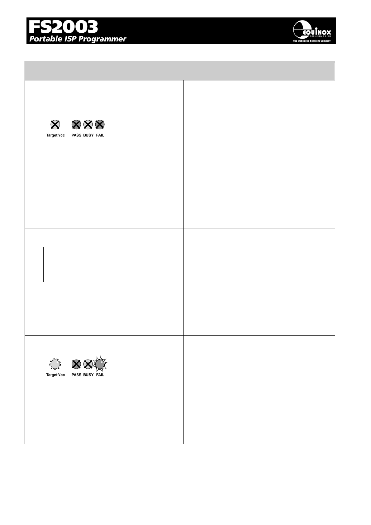
2.10 Hardware - Fault Finding Guide
i. Target Vcc LED does not illuminate when
power is applied to the Programmer /
Target System
ii. No Programming Projects Loaded
NO / INVALID
PROJECT LOADED!
• Switch power off immediately in case of
a short-circuit !
• Check that you have chosen the correct
ISP Header to connect to your Target
System.
• Check that the ISP Cable is inserted the
correct away around into the ISP Header
Socket on the Target System.
• If the Programmer is powering the Target
System, check that the ‘Vcc Jumper (J9)
is fitted.
• If Programmer and Target System are
independently powered, check that the
‘Vcc Jumper (J9) is removed. Also check
that the Vcc line from the Target System
is definitely still connected to the
Programmer Vcc pin on one of the ISP
Headers.
• If the programmer has never been used
before or the on-board FLASH Memory
Store has been erased, then the
programmer will display the message:
‘No / Invalid Project Loaded’. This is
normal as the programmer ‘FLASH
Memory Store’ is empty so the
programmer cannot be used in
Standalone Mode.
• Please upload a valid project to the
programmer using EQTools and then try
again.
iii. FAIL LED constantly flashing
• If you are running firmware 2.46 or below
then the FAIL LED will flash when you
initially power up the programmer.
• To clear the FAIL LED condition, use the
<Up> / <Down> keys to select a
Programming Project and then press the
<Yes> key .
• If there are no Programming Projects
Loaded into the Programmer – Flash
Memory Store, the FAIL LED will
continue to FLASH until at least one
Project is uploaded.
FS2003 ISP Programmer - User Guide V1.07 – 1st September 2007 34
Page 38

5
FS2003 ISP Programmer - User Guide V1.07 – 1st September 2007 3
Page 39
3.0 Programmer – Getting Started Guide
3.1 Software Overview
The FS2003 programmer is supplied with a comprehensive Integrated Development Environment
(IDE) called ‘EQTools Version 2.xx Software Suite’. This software supports creation and testing of
so-called Programming Projects which can then be uploaded to the programmer for use in
‘Standalone Mode’. EQTools contains many separate utilities most of which are enabled as standard
for this programmer. Certain options such as compiling and running of ‘Programming Scripts’ must be
purchased from Equinox as a ‘License upgrade.
The table below details the various EQTools components and whether they are enabled as standard.
Fig. 3.1 Software / Control Options for the FS2003 Programmer
EQTools - Project Builder YES
EQTools - Project Management Utility YES
EQTools - Project Upload/Download Utility YES
EQTools - Development Suite (EDS) YES
EQTools - Script Builder U
EQTools - Script Editor U
Development Mode (PC Controlled) YES
Standalone operation (Keypad – no PC) YES
ASCII Text Mode Control U
ConsoleEDS – Evaluation version YES
ConsoleEDS – PRO version U
ISP-PRO Software U
- Network Management Utility U
- Interface Database (Diagnostics Log) U
- Labview Control (PC) U
- Remote Application Control (PC) U
Key
YES – feature available as standard
U – a license upgrade must be purchased from Equinox to enable this feature.
FS2003 ISP Programmer - User Guide V1.07 – 1st September 2007 36
Page 40

7
3.2 Programmer Control Mechanisms
The programmer can be controlled from EQTools, from a Remote System and via the Equinox ISPPRO software. An overview of the various control mechanisms is given below.
Standalone Operation (Keypad)
This indicates that the programmer can be operated without being connected to a PC or other control
system. In this case an operator can control programming operations using a keypad on the
programmer e.g. Epsilon5, FS200A, FS2003, PPM3-MK2
ASCII Text Mode Control
This indicates that the programmer can be controlled using a simple 'ASCII Serial Communications
Protocol'. This is ideal for applications where a Remote System wishes to control the programmer
using a serial communications link e.g. RS-232.
ISP-PRO Software
This software suite is capable of controlling up to 16 x Equinox Production ISP programmers on an
RS-485 network at the same time. All programming operations are controlled via 'Programming
Scripts' and 'Programming Projects' which have been created using EQTools. The application
minimises user intervention during programming and logs all programming operations to an Interface
Database.
Labview Control (PC)
This allows an Equinox programmer to be controlled by a remote Labview Application. The Labview
application can launch 'Programming Scripts' and read/write unique data such as serial numbers and
calibration data.
Remote Application Control (PC)
This allows an Equinox programmer to be controlled by a Remote Application written in e.g. Visual
Basic, C++ etc. The Remote Application can launch 'Programming Scripts' and read/write unique data
such as serial numbers and calibration data.
ConsoleEDS
ConsoleEDS is a ‘console application’ running under Windows which allows the programmer to be
controlled by simple command line commands. This is an ideal control method for use with Batch
Files or any Remote Application.
FS2003 ISP Programmer - User Guide V1.07 – 1st September 2007 3
Page 41

3.3 Software Installation
The FS2003 programmer comes with the software suite called EQTools as standard. The latest
version of this software which was available at the time of shipping is supplied on CD-ROM with the
programmer. However, this software version is likely to have been superseded by a newer version.
Please check the Equinox website for the latest version of this software.
Locate the latest version of the EQTools software by browsing to:
http://www.equinox-tech.com
EQTools versions are quoted as e.g. EQTools V2.1.0 Build 640
The filename for this version would be ‘eqtools210_640.exe’
For further information, please locate the ‘EQTools – Getting Started Guide’ PDF document either
on the CD-ROM supplied with the programmer or from the Equinox Web Site. Refer to Section 3 of
the guide for detailed EQTools installation instructions.
and clicking on the ‘downloads’ tab.
FS2003 ISP Programmer - User Guide V1.07 – 1st September 2007 38
Page 42

3.4 Programmer Operating Modes
The FS2003 programmer can be controlled in various different ways as detailed in the table below:
# Programmer
Mode
Connect
to PC
COM
Port
Control Method
/ Software
Upgrade
License
Required
Functional description Refer
to
section
1 Development
Mode
2 Standalone
Mode
Yes EQTools - EDS Standard
Feature
No None Standard
Feature
In this mode, the programmer
is controlled by EQTools Equinox Development Suite
(EDS). EDS allows you to
read/write the target device
FLASH / EEPROM / FUSE /
LOCK bits interactively under
PC control without uploading
a ‘Programming Project’ to
the programmer.
In this mode, the programmer
is not connected to a PC and
can program a single
‘Programming Project’ into
the Target Device when the
<YES> key is pressed. (A
valid project must have been
previously uploaded to the
programmer using EQTools –
Upload Wizard.)
3.5
3.6
3 Script Mode Yes EQTools – Script
Debugger
or
ISP-PRO
4 ConsoleEDS Yes ConsoleEDS Upgrade
FS2003 ISP Programmer - User Guide V1.07 – 1st September 2007 39
Upgrade
Required
Required
In this mode, the programmer
is controlled from a
‘Programming Script’ running
within either the EQTools or
ISP-PRO applications on a
PC.
In this mode, the programmer
is controlled via the
ConsoleEDS utility which
allows control via simple
Command Line commands
and arguments.
3.8
See
App
Note
AN111
Page 43
5 ASCII Control
Mode
Yes ASCII Text
Communications
Upgrade
Required
In this mode, the programmer
is controlled via a simple
ASCII Protocol. A simple
Terminal Emulator is required
to test out this mode or the
ASCII commands can be
generated by an external
controller.
Key
S – feature available as standard
U – a license upgrade must be purchased from Equinox to enable this feature.
See
App
Note
AN110
FS2003 ISP Programmer - User Guide V1.07 – 1st September 2007 40
Page 44
3.5 Development Mode (EDS)
3.5.1 Overview
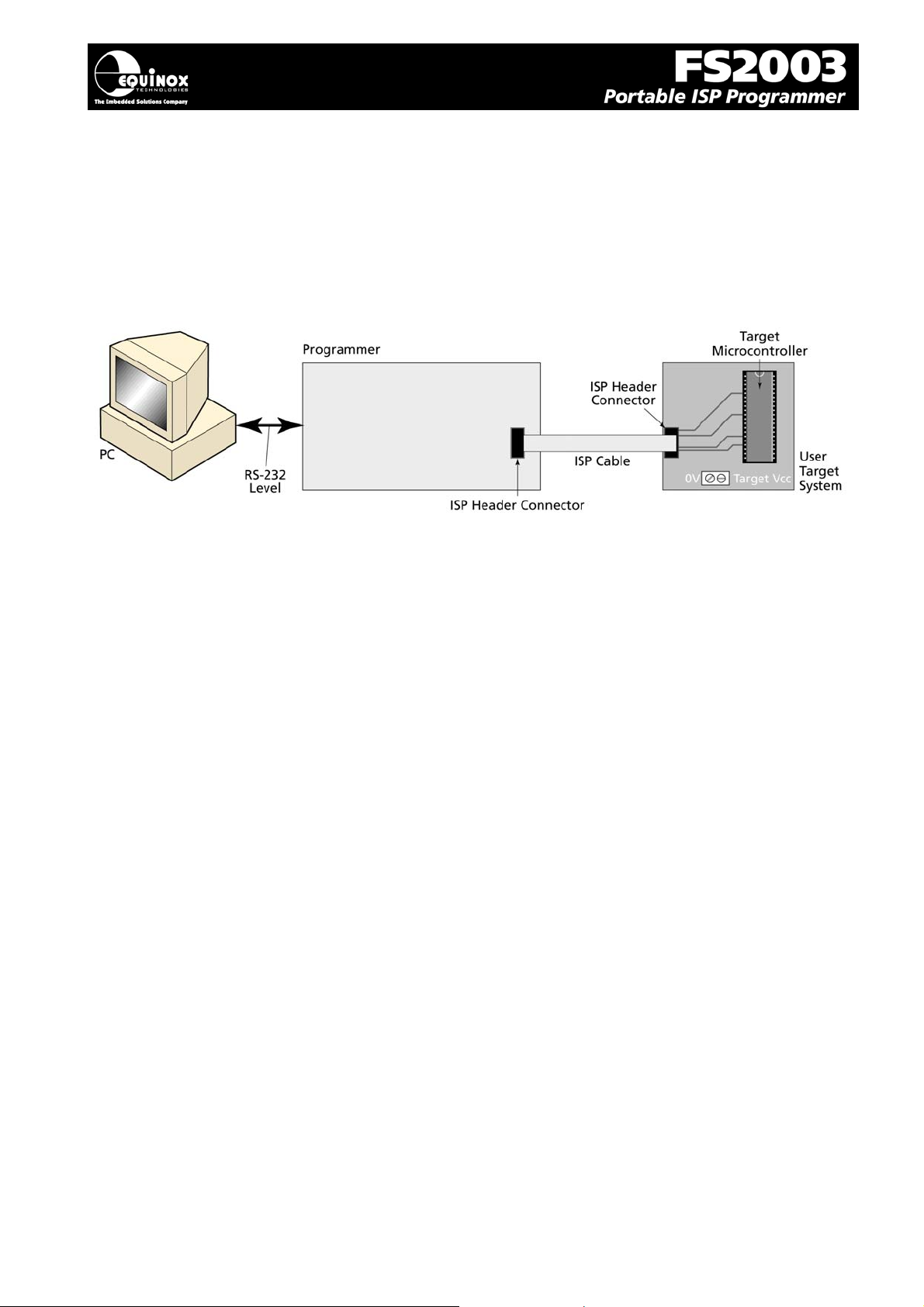
In ‘Development Mode’, the programmer is controlled from the EQTools – EDS (Equinox
Development Suite) running on a PC. The Development utility is called Equinox Development Suite or
EDS for short. In this mode it is NOT necessary to upload the ‘Programming Project’ to the
programmer as the EDS utility co-ordinates all programming operations.
In EDS Mode, you can perform the following actions under PC control:
• Write data directly to a Target Device from the PC e.g. a HEX file
• Read data from a Target Device to a file on the PC
• Write / Read the Configuration Fuses of a Target Device
• Write / Read the Security Fuses of a Target Device
• Read the Target Vcc Voltage
3.5.2 Creating a new EDS (Development Mode) Project
To test a Target Chip in EDS (Development Mode), follow the instructions detailed below:
• Launch EQTools
• From the Welcome Screen, select the ‘Create a new Equinox Development Project (EDS)’
option.
OR
• From the left-hand pane, select the <Development> tab and then select ‘New Development
Project’.
Æ The EDS Wizard will now launch
• Follow the EDS Wizard by filling in each tab and then clicking the <Next> button:
• Select Programmer – click <Get Info> button to detect your attached programmer
• Select Project Type – leave as the default ‘Standalone Keypad Operation’
• Select Device – This is your Target Chip.
• Select Target Oscillator – If unsure of settings leave all settings as the defaults and click
<Next>.
• Select Target Voltage
• Select FLASH Data File (optional – you can enter the file name at a later stage in EDS)
• Select EEPROM Data File (optional – you can enter the file name at a later stage in EDS)
FS2003 ISP Programmer - User Guide V1.07 – 1st September 2007 41
Page 45

• At the end of the EDS Wizard:
Click the <Test> button
Save the EDS file with an appropriate name eg. ATmega163.eds
Æ The EDS Window will now launch – see section 2.5.4
3.5.3 Testing an existing Programming Project in a Project Collection in
EDS (Development Mode)
If you have already created a Programming Project and want to test it in EDS (Development Mode),
please follow the steps below:
o From the left-hand pane, select <Project Manager>
o Select <Open Collection>
o Browse to and select a Project Collection (*.ppc) file
Æ Project Collection File launches in Project Manager view
o Select the Programming Project you wish to test in EDS
o Click the <Test Project in EDS> button at the bottom right of the Project Manager window
o Æ The EDS window now launches with all the settings of the select Programming Project –
see section 3.5.4
FS2003 ISP Programmer - User Guide V1.07 – 1st September 2007 42
Page 46
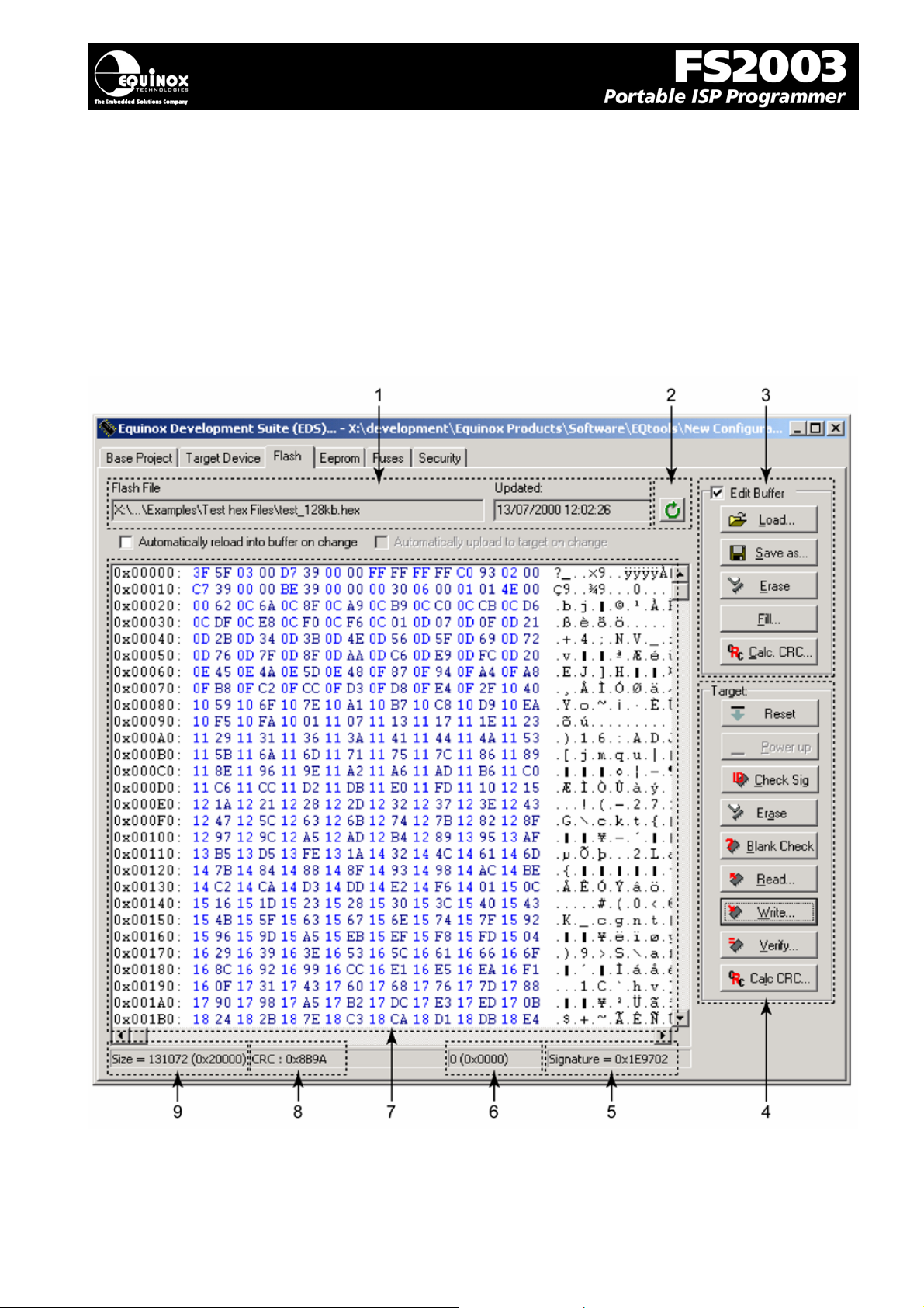
3.5.4 Overview of EDS – Development Mode
The EDS Utility consists of a series of tabs. Each tab controls a different area of functionality including
FLASH Area Programming, EEPROM Area programming, Configuration Fuse Programming and
Security Fuse programming. It is also possible to set up the SPI / JTAG / UART Target Speeds and
the Power Supply Settings from EDS.
Fig. 3.5.4.1 EDS – FLASH Tab Overview
FS2003 ISP Programmer - User Guide V1.07 – 1st September 2007 43
Page 47
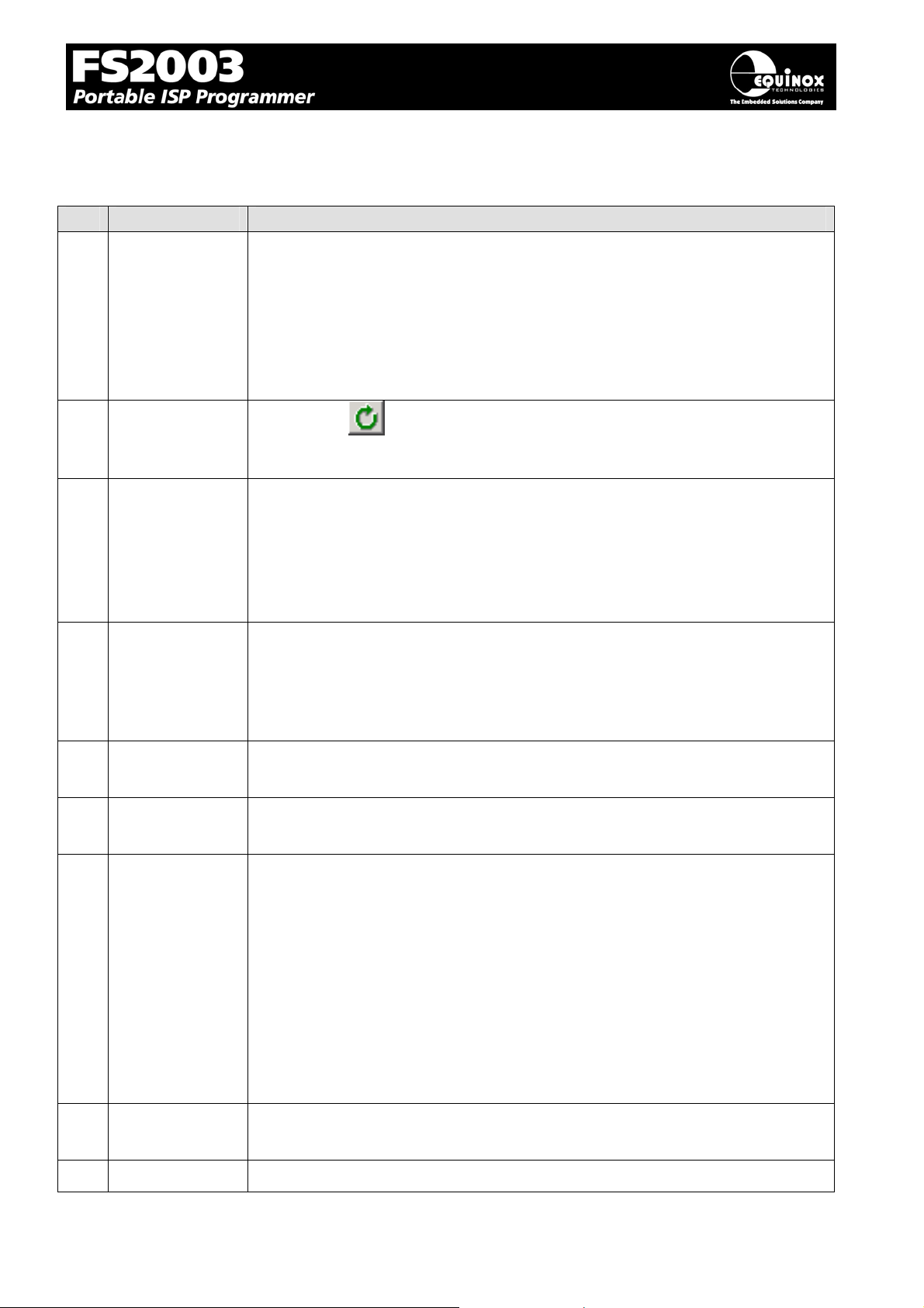
Fig.3.5.4.2 FLASH / EEPROM tab – functional description
#
1
File name and
properties
This specifies the ‘File Name / path’ and ‘Last updated’ date of the file to be
loaded into the Buffer Window.
• By default, this will point to the file specified in the associated
Programming Project (*.ppm).
• To load a different file, click the <Load> button and browse to the
required file.
2
Re-load file to
buffer
Clicking the
Buffer Window.
icon re-loads the specified Flash / EEPROM file into the
This will overwrite any information already in the Buffer Window.
3
Buffer Control
Buttons
This group of buttons control operations on the EDS – Buffer Window.
• To use these buttons or to manually edit the Buffer Window, it is
necessary to check the ‘Edit Buffer’ check box.
4
5
6
7
• This extra step helps to avoid accidental modification of data in the
buffer.
Target Control
Buttons
This group of buttons control operations on the actual Target Device.
• A programmer and suitable Target System must be connected
when using these buttons.
Signature of
This is the signature (Device ID) which is expected for the Target Device.
Target Device
Buffer
This is the address of the currently selected location in the Buffer Window.
Address
Buffer Window The Buffer Window displays a hexidecimal and alphanumeric
representation of the data which has either been loaded from file or read
back from a Target Device.
• The bytes are grouped into rows of 16 bytes with the start address
of each row displayed in the left-hand column.
• The Hexadecimal representation of the 16 bytes is displayed in the
middle column
8
9
• The ASCII representation of the 16 bytes is displayed in the righthand column.
CRC This is a CRC Checksum of the entire Buffer (i.e. from address 0x00000 to
the end address specified in the buffer.)
Size This is the physical address range in bytes of the entire Buffer.
FS2003 ISP Programmer - User Guide V1.07 – 1st September 2007 44
Page 48
5
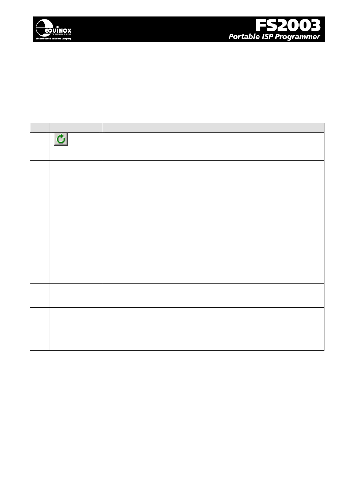
3.5.5 Buffer Window - Control Buttons
The Buffer Window within EDS is used as a virtual data store which allows data to be transferred from
file Æ Buffer Window Æ Target Device and vice-versa.
The ‘Buffer – Control Buttons’ support operations on the data in the Buffer Window, including loading
a file into Buffer or saving the contents of the Buffer to file. These buttons do NOT initiate any actual
programming operation of the Target Device.
# Button Description / Purpose
1
2
3
Re-load File
Edit Buffer
<Load> • This button allows you to manually browse to select a file to be load
• Re-loads the specified HEX / Binary file into the Buffer Window.
• Tick the box to enable manual editing of the Buffer Window.
• This will also allow the <Load>, <Erase> and <Fill> buttons to be
selected.
into the Buffer Window.
4
5
6
7
• The path will default to the path set up in the Programming Project
(if a file is specified).
<Save as> • This button allows you to save the contents of the Buffer Window to
a file.
It is possible to specify the following properties for the file:
• File type (HEX / Binary)
• File Start and End Address
<Erase> • This button erases the entire contents of the Buffer Window.
• All locations are set to the value 0xFF.
<Fill> • This button allows you to fill a specified area of the Buffer Window
with a specified value.
Calc CRC • This button calculates the CRC Checksum of the specified range of
the Buffer Window.
FS2003 ISP Programmer - User Guide V1.07 – 1st September 2007 4
Page 49

3.5.6 Example of using EDS
Here is an example of how to use EDS:
• Select the <FLASH> tab
• Click the <Load> button to load a file
• Click the <Check Sig> button to check the Device Signature of the Target Chip
• Click the <Write> button to write the data in the Buffer Window to the Target Device
• Click the <EEPROM> tab to select operations on the EEPROM area of the Target Chip/
• Click the <Fuses> tab to read / write the Target Chip ‘Configuration Fuses’
• Click the <Security> tab to read / write the Target Chip ‘Security Options’
For further instructions about how to use the EDS utility, please refer to the ‘EQTools – Getting
Started Guide’ which can be found on the CD-ROM supplied with the programmer
FS2003 ISP Programmer - User Guide V1.07 – 1st September 2007 46
Page 50
7
3.6 Standalone Keypad Mode
3.6.1 Overview
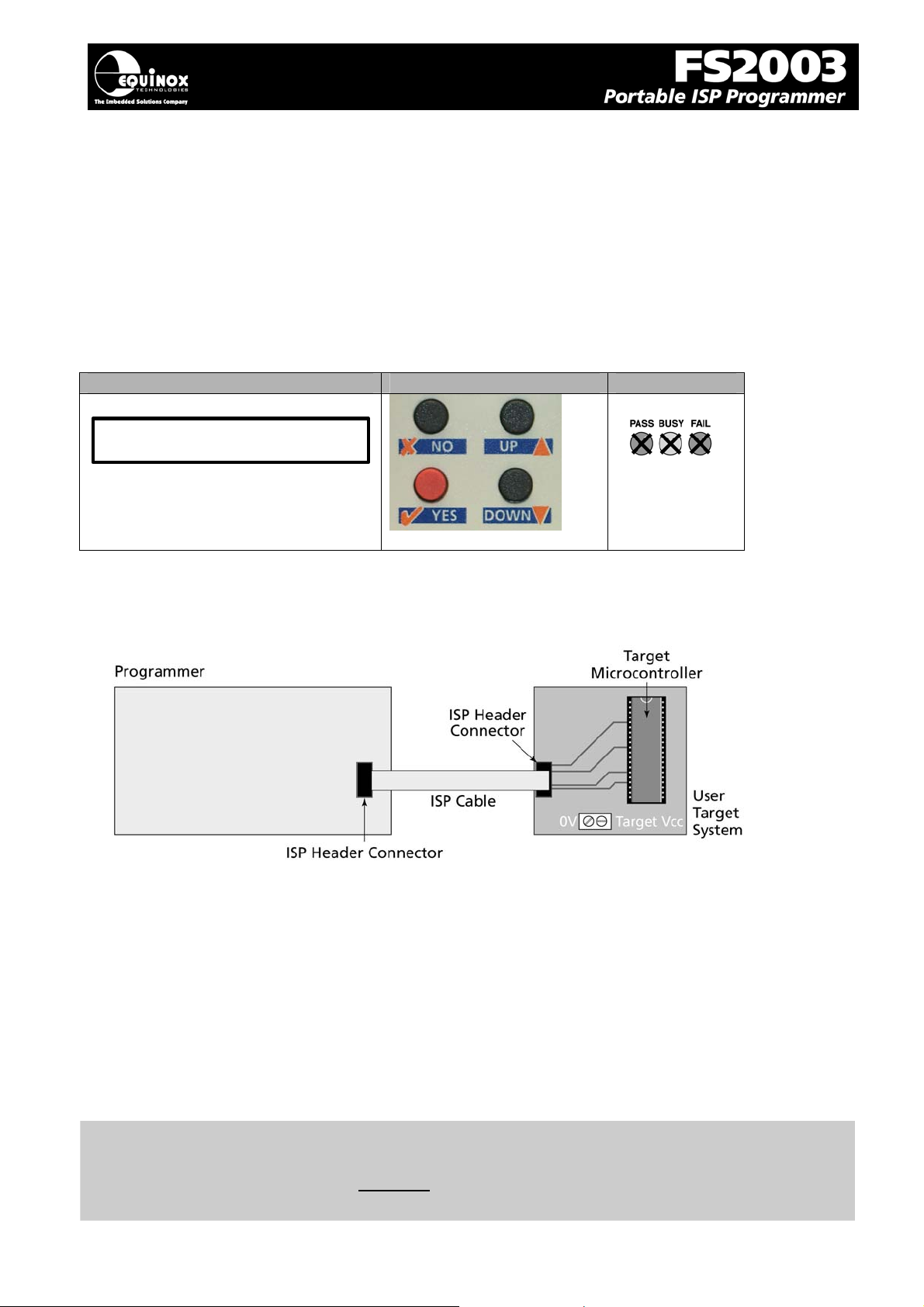
In ‘Standalone Mode’, the FS2003 is controlled via the push buttons on the front panel of the
programmer. The programmer LCD and the LED Status Indicators are used to display the current
status of the programmer. In Standalone Mode it is possible to select from 1 of 64 previously
uploaded Programming Projects and then to repeatedly execute this project to program a batch of
devices.
LCD Display Buttons Status LED’s
PRESS YES TO
PROGRAM TARGET
This mode is ideal for both field and production ISP requirements as the programming data is held
locally in FLASH memory on the programmer so a PC is not required.
Before using Standalone Mode you need to:
• Connect Programmer to PC COM port
• Upload a valid Project Collection to containing 1 – 64 Programming Projects to the
programmer. This will be retained in the Programmer ‘Flash Memory Store’ even once the
power is removed.
• It is a good idea to test these projects using EDS (Equinox Development Suite) before
uploading them to the programmer.
• Disconnect the programmer from the PC
Please note:
It is recommended that all Programming Projects are fully tested and debugged using the EDS
(Equinox Development Suite) utility BEFORE uploading them to the programmer. This can save a lot
of time as problems are much easier to debug within the EDS environment.
FS2003 ISP Programmer - User Guide V1.07 – 1st September 2007 4
Page 51
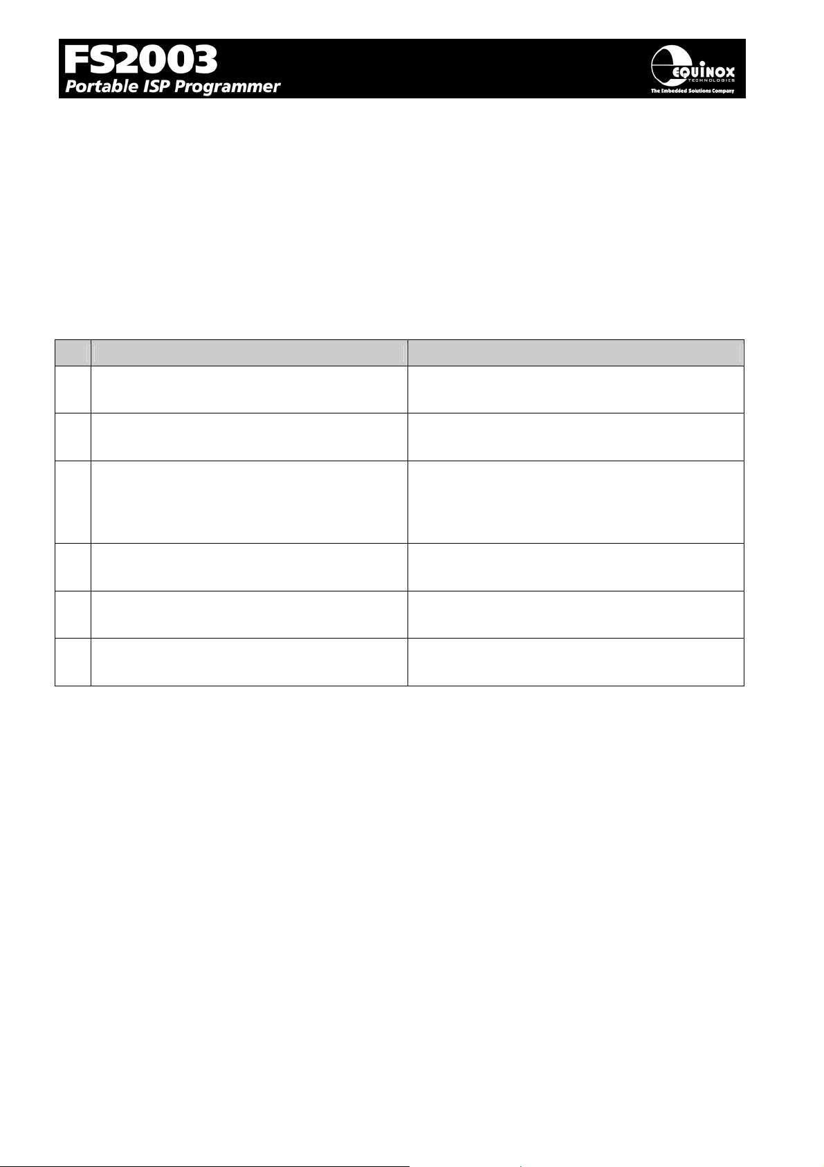
In Standalone Mode you can:
• Select from 1 of up to 64 Independent Programming Projects using the keypad and display
• Plug the Programmer ISP cable into a Target System
• Program the selected Programming Project into the Target Device
• Unplug the Programmer ISP Cable from the Target System
• Plug the Programmer ISP Cable into the next Target System
• Repeatedly program the same Programming Project once it is selected
To execute a Programming Project in Standalone Mode:
# Action Observation / comment
1 Connect the programmer to a spare PC COM
port
2 Apply power to the Programmer / Target
System
3 Upload your ‘Programmi ng Project(s)’ to the
programmer
4 Disconnect power from the Programmer /
Target System
5 Disconnect the serial lead from the
programmer
6 Follow the instructions to program the Target
Device in Standalone Mode
Æ Programmer Target Vcc LED illuminates
See EQTools Manual – Project Upload Wizard
for full instructions.
Æ Programmer is no longer controlled from PC
FS2003 ISP Programmer - User Guide V1.07 – 1st September 2007 48
Page 52
3.6.2 Push Button Functions
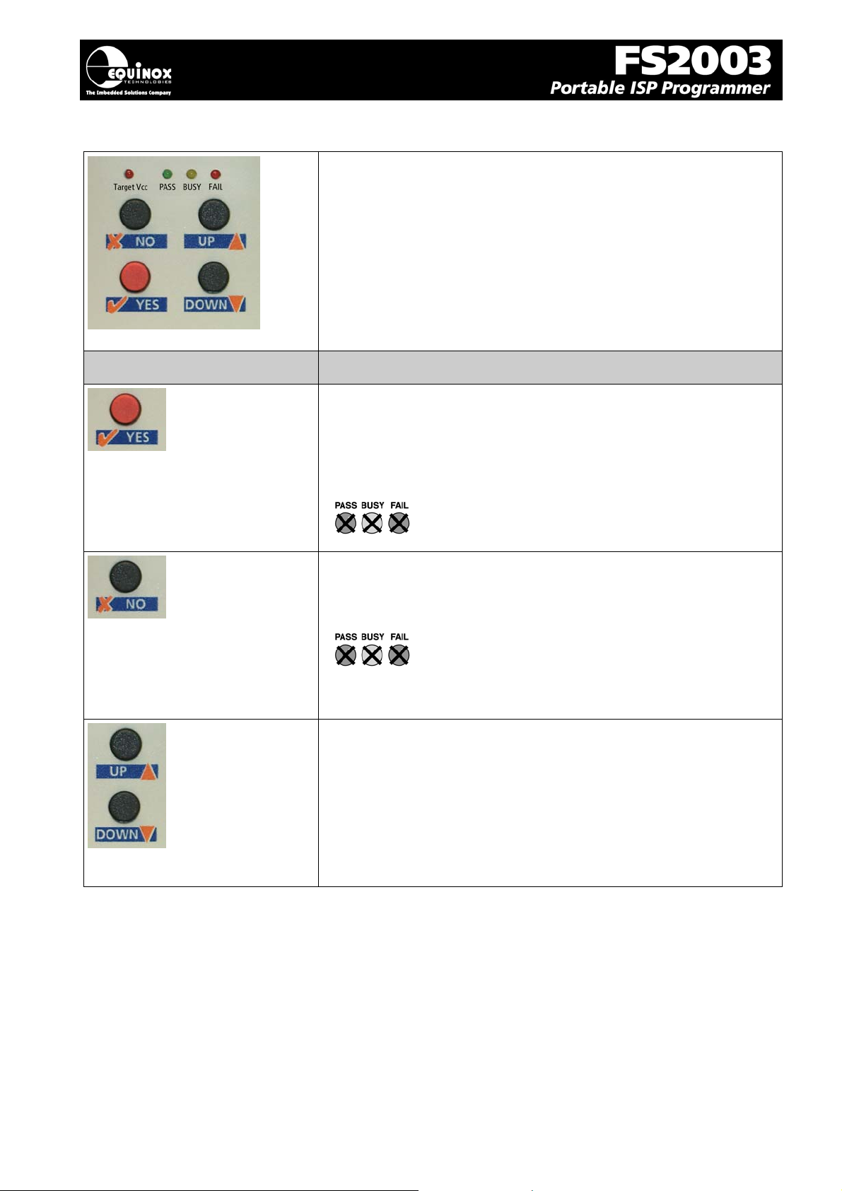
The FS2003 programmer features a four button keypad which is
used to control the programmer when it is operating in
‘Standalone Mode’.
The function of these buttons is described below.
Button Function of button
The <YES> button has the following functions:
i. To execute a programming project which has been pre-loaded
into the programmer ‘FLASH Memory Store’.
ii. To return to the ‘Standby’ state
The <No> button has the following functions:
i. To cancel a programming action
ii. To return to the ‘Standby’ state
• The <Up> and <Down> buttons are used to scroll up and
down through the list of available ‘Programming Projects’
stored in the programmer ‘FLASH Memory Store’.
• If there are not ‘Programming Projects’ currently in
memory, then pressing thee buttons will have no effect.
FS2003 ISP Programmer - User Guide V1.07 – 1st September 2007 49
Page 53
3.6.3 Standalone Keypad Operation – step-by-step guide
The instructions below detail how to operate the programmer in Standalone Mode using the
programmer keypad and LCD. A PC is not required while operating in Standalone Mode.
1. Ensure that you have already uploaded a valid ‘Project Collection’ to the programmer
• Use the EQTools – Upload Wizard to upload your ‘Project Collection’.
• Use the new Standalone Upload Wizard Utility to upload your ‘Project Collection’. (software
upgrade required)
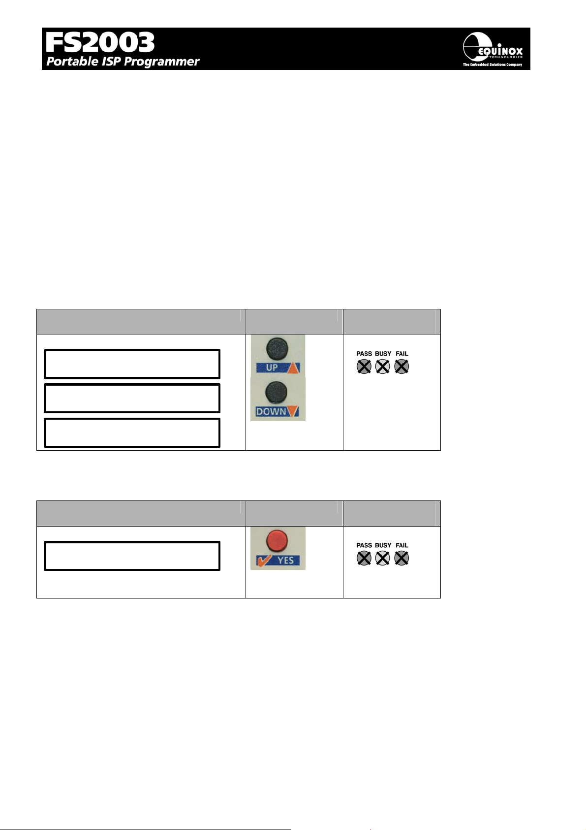
2. Select the ‘Programming Project’ which you wish to execute:
• Use the <UP> and <Down> keys to move up and down the list of projects currently resident in
the programmer ‘FLASH Memory Store’.
• If there is one ‘Programming Project’ resident in the programmer, then this project will be
displayed permanently on the LCD.
• If Project Version Control has been enabled for the project(s), then the project version
information will be displayed on the bottom line of the LCD.
LCD Display Buttons Status LED
Display
Select Project
Project1
Select Project
Project2
Select Project
Project3
3. Press the RED <YES> button to select the Programming Project
LCD Display Buttons Status LED
Display
Select Project
Project1
FS2003 ISP Programmer - User Guide V1.07 – 1st September 2007 50
Page 54
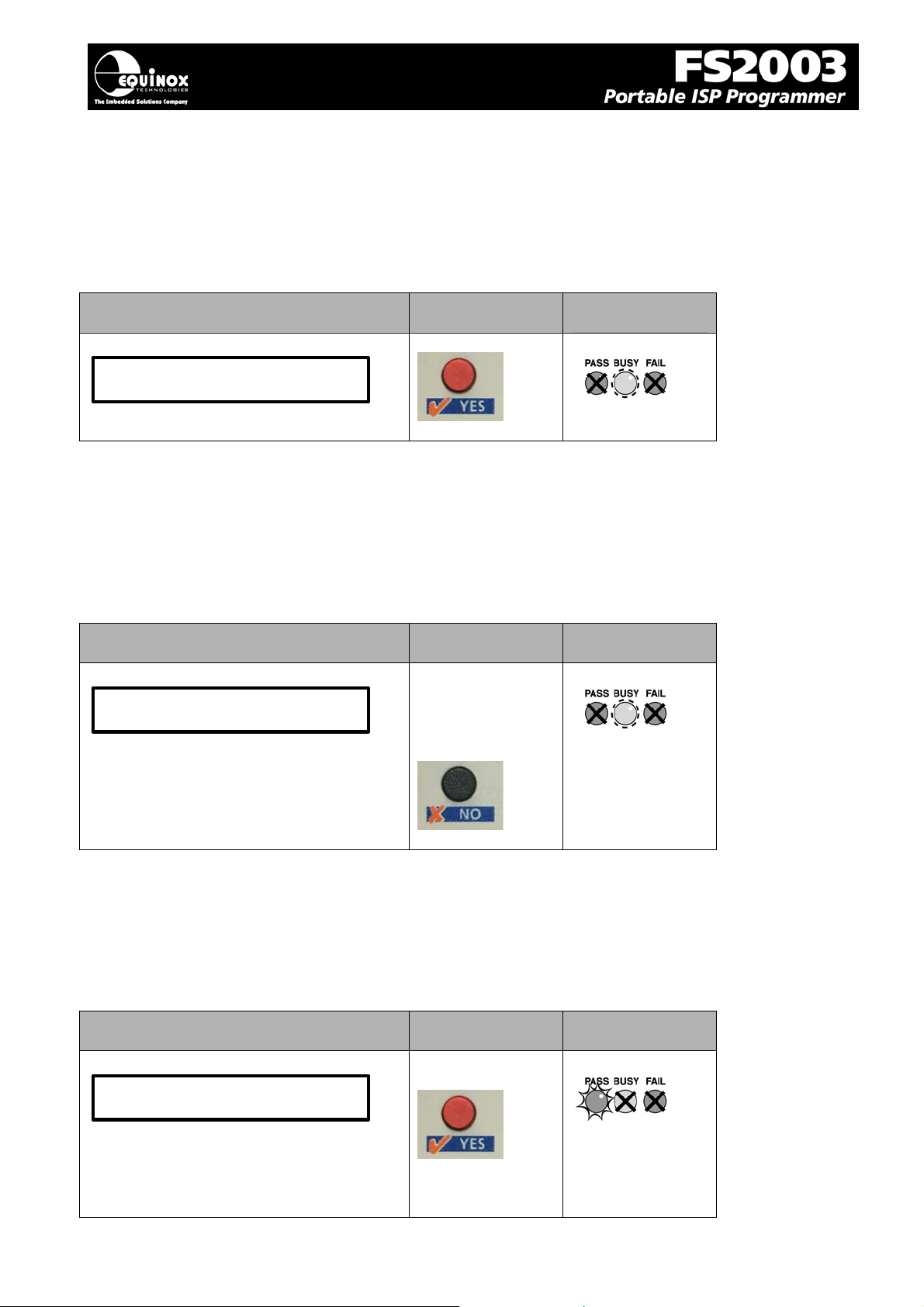
4. Wait for the programmer to CRC check the Programming Project
• The programmer performs a full CRC validation check of the entire Programming Project
stored in the programmer ‘FLASH Memory Store’.
• If the check is OK, the programmer goes to step (5).
• If the check FAILS, the programmer will display ‘Internal Image is corrupted’. Please try re-
uploading your Project Collection and then repeat the Standalone Mode process from the
beginning.
LCD Display Buttons Status LED
Display
CHECKING IMAGE
PAGE n
5. Press the RED <YES> button again to execute the Programming Project
• The Programming Project will now start to execute.
• The <BUSY> LED will illuminate to denote that the programmer is active.
• This may take a few seconds or a few minutes depending on the nature of the Programming
Project.
• The Programming Project will either PASS or FAIL
LCD Display Buttons Status LED
Display
Current programming
operation is displayed
To abort the
programming
sequence at any
time, press
6. Programming Project – PASS
If the Programming Project programs the target device without any errors:
• The <PASS> LED will FLASH
• The LCD will display: ‘Operation Complete OK!’
• Press <YES> key to program another device
LCD Display Buttons Status LED
Display
OPERATION
COMPLETE OK
Press
To program
another device.
FS2003 ISP Programmer - User Guide V1.07 – 1st September 2007 51
Page 55
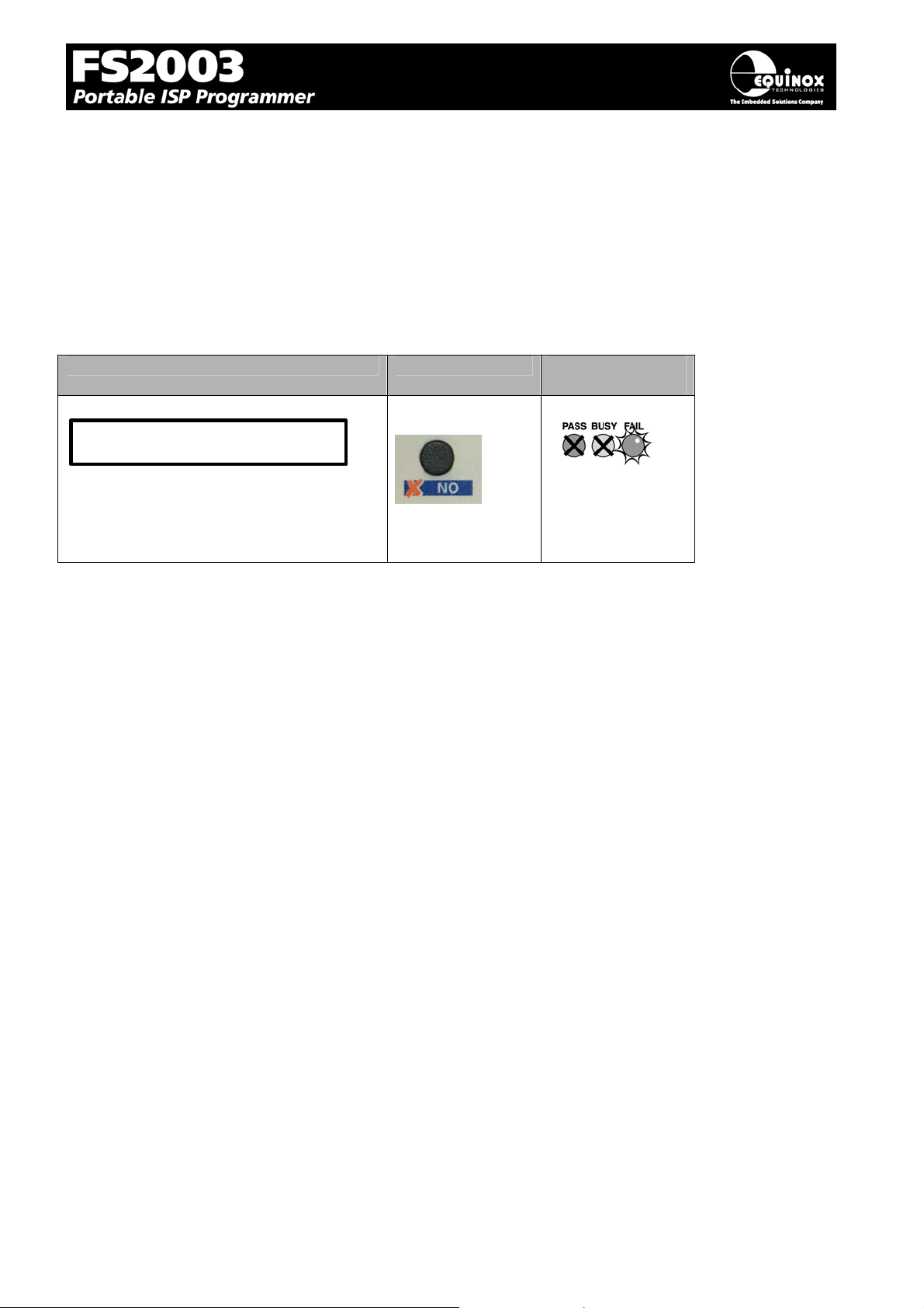
7. Programming Project – FAIL
If the Programming Project fails for some reason:
• The <FAIL> LED will FLASH
• The programmer will automatically remove power from the Target System (if the programmer
is controlling power)
• The LCD will display the relevant Error Message.
• The List of possible Error Message can be found in the ‘Error Messages’ section of this
manual.
• Press the <NO> button to clear the Error Message
• Press <YES> key to program another device. The programmer then goes back to step 3.
LCD Display Buttons Status LED
Display
ERROR
MESSAGE
Press
to clear the error
message.
8. Locking the Programmer Keypad
It is possible to lock the programmer keypad so that the <Up> and <Down> keys no longer work in
Standalone Mode. This will stop a user being able to select any other project stored in the
programmer once the initial project has been selected.
To lock the Programmer Keypad:
• Open your Programming Project in Project Builder or EDS
• Select the <Programmer and Project Type> tab
• Check the ‘Lock Keypad’ box
• Re-compile the project
• Upload the project to the programmer
Please note:
This feature is only available in firmware 3.01 or above.
FS2003 ISP Programmer - User Guide V1.07 – 1st September 2007 52
Page 56
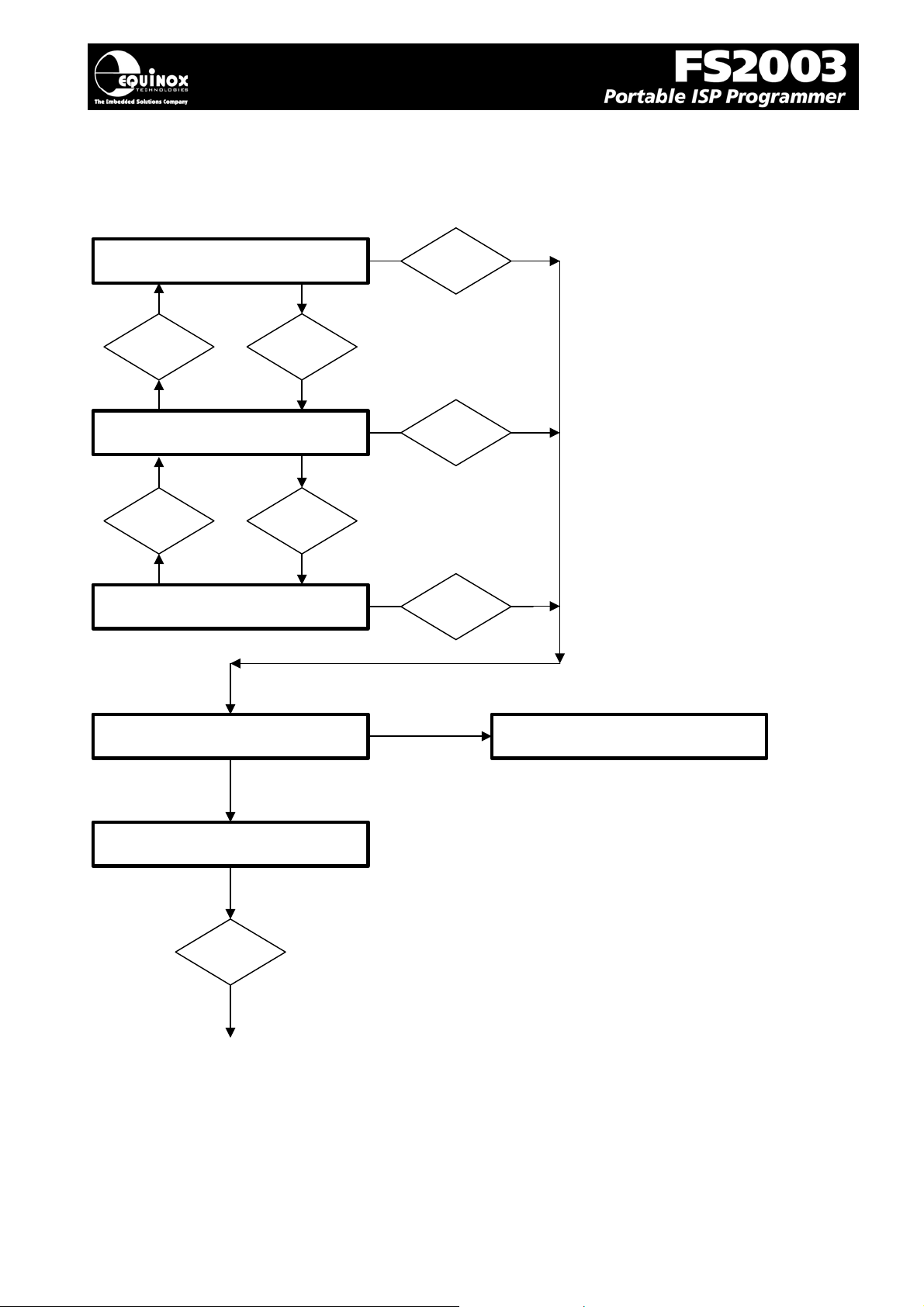
3.6.4 Standalone Keypad Operation – Flowchart
The flowchart below details how a ‘Programming Project’ is selected in ‘Standalone Mode’.
<UP>
key
<UP>
key
Select Project
T
Select Project
T
Select Project
Project1
Project2
Projectn
<DOWN>
key
T
<DOWN>
key
T
<YES>
key
<YES>
key
<YES>
key
T
T
T
CHECKING IMAGE
PAGE n
PRESS YES TO
PROGRAM TARGET
<YES>
key
T
Execute Selected Project
FAIL
INTERNAL IMAGE
IS CORRUPTED
FS2003 ISP Programmer - User Guide V1.07 – 1st September 2007 53
Page 57
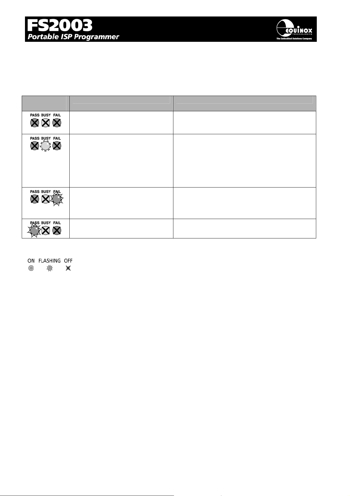
3.6.5 Programmer Status LED’s
The current status of the programmer is displayed on the programmer Status LED’s as detailed in the
table below.
Fig. 2.6.5 Programmer Status LED’s – state descriptions
Status LED
Display
Status LED key:
State State Description
WAITING
BUSY
FAIL
PASS
• Programmer is now waiting to start an
‘Autoprogram’ operation.
• Programmer is ‘BUSY’ performing a
programming operation.
• If the programmer is controlled from
EDS, the BUSY LED will remain on
after a programming operation until a
‘RESET programmer’ command is
executed.
• Programming operation has FAILED.
• See programmer LCD for diagnostics
• Programmer will automatically switch off
target power if it is controlling power.
• Programming operation was successful.
FS2003 ISP Programmer - User Guide V1.07 – 1st September 2007 54
Page 58
5
3.7 ASCII Text Communications Mode
3.7.1 Overview
The ‘ASCII Text Control’ communications protocol or ‘ATC’ is designed as a simple way for a Remote
Test System to control the basic programming operations of an Equinox programmer via an RS-232
serial link. It is an ‘ASCII’ protocol with simple commands to initiate programming of pre-loaded
‘Programming Projects’ which are stored in the on-board ‘FLASH Memory Store’ of the programmer.
The protocol supports up to 64 independent Programming Projects per programmer, but is limited to
one programmer.
Implementation of this protocol is straightforward due to the limited number of commands and
restricted functionality. As this is an ASCII protocol, it can be quickly evaluated using any Terminal
Emulation Software Utility such as Hyperterminal.
3.7.2 Programmers supported
The Equinox programmers which are capable of supporting ‘ASCII Text Mode’ control are listed in the
table below.
Programmer ASCII Text Mode Control Order Code
EPSILON5 License upgrade required EPSILON5A1-UPG6
FS2000A License upgrade required FS2000A-UPG7
FS2003 License upgrade required FS20003-UPG7
PPM3 MK1 Enabled as standard N/A
PPM3 MK2 Enabled as standard N/A
Please note:
1. The PPM3 range of Production ISP Programmers are enabled for ‘ASCII Text Mode’ control
as standard. The ‘Communications Node Address’ must be set to address ‘0’.
2. A license upgrade is required for all other programmers to enable them for ‘ASCII Text Mode’.
3.7.3 Limitations of this protocol
This protocol has been designed as a simple method to allow a Remote Application such as an InCircuit Tester to control the basic operations of an Equinox programmer. The programmer only
supports the programming of entire ‘Programming Projects’ which are already uploaded to the
programmer on-board FLASH memory. This protocol does not support writing / reading of individual
bytes or blocks of data to / from a Target Device.
The limitations of this protocol are as follows:
1. The protocol only supports programming of Programming Projects which are pre-loaded into
the Programmer on-board FLASH Memory Store.
2. The protocol does not support writing / reading of individual bytes or blocks of data to / from a
Target Device.
3. The protocol does not support uploading of ‘Programming Projects’ to the programmer. This
must be performed using the EQTools – Project Upload Wizard.
4. Only very li mited diagnostics are available using this protocol ie. FAIL + Error Number.
FS2003 ISP Programmer - User Guide V1.07 – 1st September 2007 5
Page 59

3.7.4 Further Information
A full description of this protocol can be found in the Application Note ‘AN110 - ASCII Text Control
(ATC) Protocol for Remote Control of Equinox Programmers’.
FS2003 ISP Programmer - User Guide V1.07 – 1st September 2007 56
Page 60

7
3.8 Script Mode
‘Script Mode’ is designed for production users who require logging of all programmer operations to a
database. This mode utilises the Equinox ISP-PRO software which allows execution of Programming
Scripts. It is possible to write scripts to program unique data such as serial numbers, calibration data
etc. It is also possible to control the programmer from a Remote Application written in e.g. Labview,
Visual Basic, C++ etc.
In order to use ‘Script Mode’ with your programmer, it is necessary to purchase the relevant license
upgrade for ISP-PRO.
FS2003 ISP Programmer - User Guide V1.07 – 1st September 2007 5
Page 61
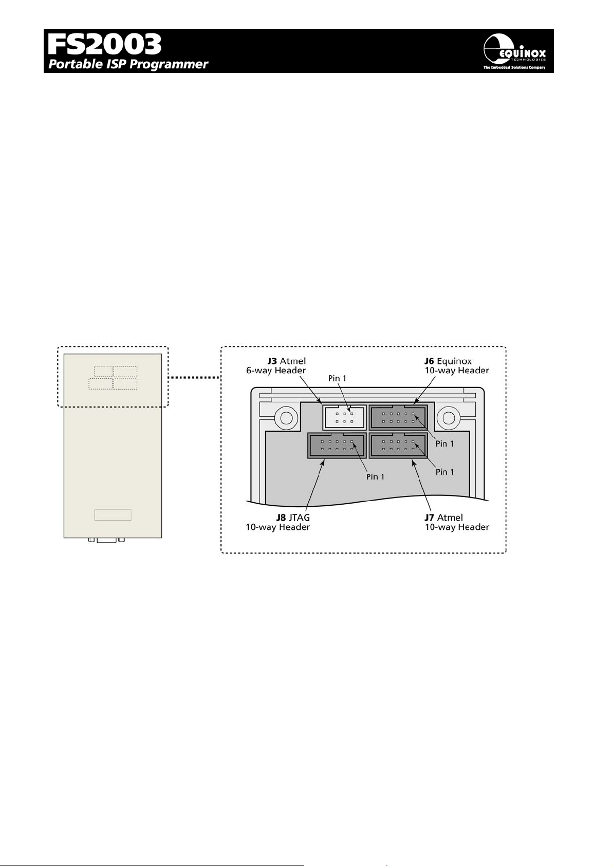
4.0 ISP Header Selection
4.1 Overview
The FS2003 programmer caters for many different connection methods to a Target System by
featuring FOUR possible ISP Header connectors. Each header provides the necessary signals to
program the Target Device plus Vcc (power) and GND (Ground). The choice of which header to use
depends on the ‘device type’ and the algorithm being employed to program the device.
To locate the ISP Headers (J3, J6, J7 & J8), remove the four screws from the back of the programmer
and then carefully remove the lid. If you hold the programmer with the RS-232 connector towards
your, the four ISP headers will be in the positions shown in the figure below. Pin 1 is designated on
each header and should match with the corresponding pin 1 of the cable to be plugged into the
header.
Please see section 4.2 for an overview of each ISP Header.
FS2003 ISP Programmer - User Guide V1.07 – 1st September 2007 58
Page 62
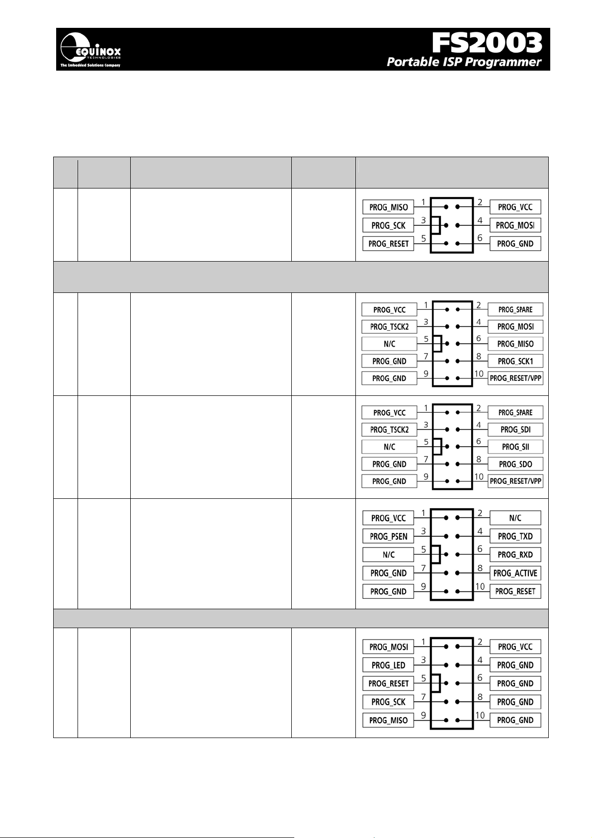
4.2 ISP Header Selection Chart (by header)
The FOUR ISP Headers featured on the FS2003 are detailed in the table below. Please refer to the
section indicated in the ‘refer to section’ column for specific details of each header.
# ISP
Header
Description / Function Refer to
section
ISP Header Pin-out
1 J3 Atmel 6-way ISP Header
Header J6 can have THREE different pin-outs depending on which Target Device is to be
programmed. See (2a), (2b) and (2c).
2a J6(a) Equinox 10-way Header(a)
Device support:
Atmel AT90S, ATmega, ATtiny,
AT89S devices
2b J6(b) Equinox 10-way Header(a)
Device support:
Atmel ATtiny11/12/15
High Voltage (+12V Vpp)
Programming Mode
4.4
4.5
4.6
2c J6(c) Equinox 10-way Header(b)
Device support:
Atmel Wireless T89C51Rx2
Philips P89C51Rx2 / 66x
3 J7 Atmel 10-way Header
Device support:
Atmel AT90S, ATmega, ATtiny,
AT89S devices
4.7
4.8
FS2003 ISP Programmer - User Guide V1.07 – 1st September 2007 59
Page 63
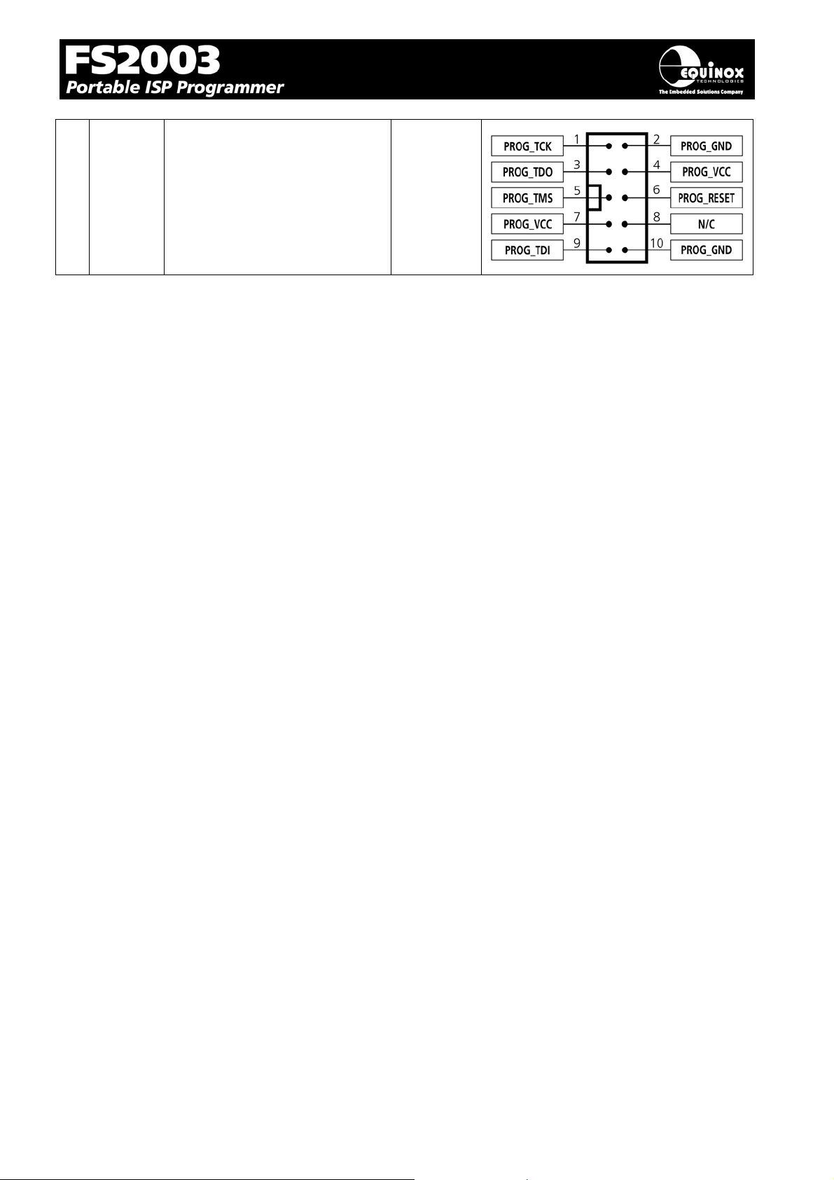
4 J8 Atmel 10-way JTAG Header
Device support:
Atmel ATmega32/128 + any
new devices with JTAG port
4.9
FS2003 ISP Programmer - User Guide V1.07 – 1st September 2007 60
Page 64
4.3 ISP Header Selection Chart (by Device)
The table below details which header to choose for a specified device or device family. The
information contained in this manual does NOT show the actual connections to the Target
Microcontroller. Please refer to the separate Application Notes ( see App Note column in table below )
for full details of how to implement In-System Programming for your selected device.
Please note:
• The Atmel ATmega323/128/64 devices can be programmed via ‘LV SPI’ or ‘JTAG’ by
connecting the relevant header to the SPI or JTAG port of the device.
• The header J6 is multi-functional. The pin-out of this header is different depending on which
device type is being programmed.
# Device Family Devices Algorithm Header Sect. App
Note
1 Atmel AT89S AT89(L)S51/52/53/8252 LV SPI J6(a)
J7
2 Atmel AT90S (AVR) All AT90S ISP devices LV SPI J6(a)
J7
3 Atmel ATmega (AVR) All ATmega devices LV SPI J6(a)
J7
4 Atmel ATmega (AVR) ATmega323/128/64 JTAG J8 4.9 AN105
5 Atmel ATtiny (Low Voltage) All ATtiny ISP devices LV SPI J6(a)
J7
6 Atmel ATtiny (High Voltage) ATtiny11/12/15L HV SPI J6(b) 4.6 AN104
7 Atmel W&uC (Temic)
T89C51Rx2
8 NXP (formerly Philips)
P89C51Rx2
T89CRB2/RC2/RD2 UART
Boot
Loader
P89CRB2/RC2/RD2 UART
Boot
Loader
J6(c) 4.7 AN106
J6(c) 4.7 AN106
4.4, 4.5
4.8
4.4, 4.5
4.8
4.4, 4.5
4.8
4.4, 4.5
4.8
AN103
AN100
AN101
AN104
AN107
9 NXP (formerly Philips)
P89C66x
10 Zensys Z-Wave ZW0102 / ZW0201 LV SPI J6(a) 4.5 See
FS2003 ISP Programmer - User Guide V1.07 – 1st September 2007 61
P89C662/4/8 UART
Boot
Loader
J6(c) 4.7 AN106
AN107
Zensy
App
Note
Page 65
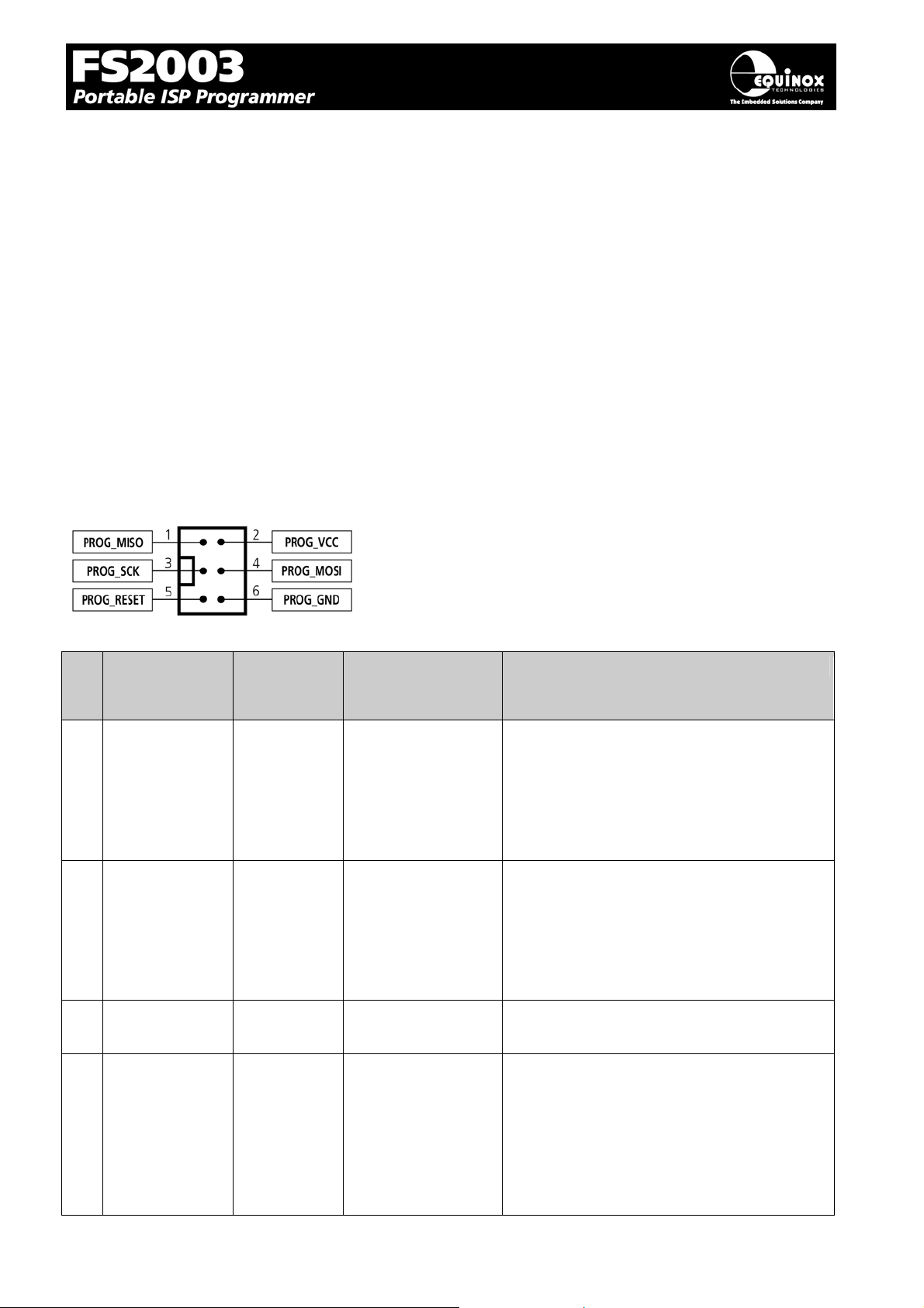
4.4 J3 - Atmel 6-way ISP Header (SPI Interface)
A
A
This connection method is suitable for interfacing the programmer to a Target System which features
the following:
• Atmel 6-way IDC ISP Header
• An Atmel device which features the 3-wire SPI + RESET Programming Interface
The 6-way IDC box header is the most compact header i.e. takes up least space on the Target
System and so is very popular for designs where PCB space is limited. Unfortunately, this connection
method does not have any pins spare for extra functionality such as the SCK2 Oscillator so it should
only be used if this functionality is not required.
To implement this connection method, simply plug a 6-way ISP cable (not supplied) into the
Programmer ISP Header J3 and plug the other end of the cable into the matching header on the
Target System.
Figure 4.4.1 - Atmel 6-way IDC Header (J3) viewed from above
Warning!
Connecting to the wrong ISP Header may cause catastrophic
damage to the Programmer & Target System
Pin
Programmer
No
Pin name
1 PROG_MISO I MISO
2 PROG_VCC P TARGET_VCC Target Vcc
Programmer
Input /
Output
Connect to
pin on
Target Device
(except for
Tmega103/128/64
– connect to TXD
pin instead)
Description
Master In Slave Out
This is the SPI data input pin to the
programmer. This pin should be
connected to the MISO pin on the Target
Microcontroller.
This pin should be connected to the
Target System Vcc. This voltage could be
used to power the programmer depending
on the settings of the power switch/jumper
on the programmer.
3 PROG_SCK1 O SCK SPI Serial Clock Output
This is the SPI clock output signal.
4 PROG_MOSI O MOSI
(except for
Tmega103/128/64
– connect to RXD
pin instead)
FS2003 ISP Programmer - User Guide V1.07 – 1st September 2007 62
Master Out Slave In
This is the SPI data output pin from the
programmer. This pin should be
connected to the MOSI pin on the Target
Microcontroller.
Page 66

5 PROG_RESET O RESET Target RESET control pin
This pin controls the Target Device
RESET pin. It will driven HIGH/LOW
according to the device type and settings
in the ‘Pre-program State Machine’ tab in
the Eqtools project.
6 PROG_GND P GROUND Ground Connection
Common ground connection between
PROGRAMMER and Target System.
Key
O - Output from programmer to Target Device
I - Input to programmer from Target Device
P - Passive eg. GROUND and power rails
N/C - Not connected
FS2003 ISP Programmer - User Guide V1.07 – 1st September 2007 63
Page 67
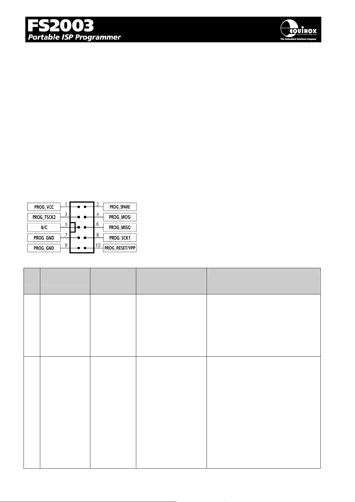
4.5 J6(a) - Equinox 10-way Header (Generic SPI Interface)
This connection method is suitable for interfacing the programmer to a Target System which features
the following:
• Equinox 10-way IDC ISP Header
• An Atmel device which features the 3-wire SPI + RESET Programming Interface
This is the favoured ISP connector as it allows the following additional functions:
• Application of +12V Vpp for ATtiny High Voltage Serial Programming
• SCK2 Oscillator for clocking devices during programming
• Spare I/O pin which could be used for SPI SLAVE SELECT or to drive an LED on the Target
System
To implement this connection, simply plug the 10-way ISP cable into the Programmer J6 header and
plug the other end of the cable into the matching header on the Target System.
Figure 4.5.1 – Equinox 10-way IDC Header (J8) viewed from above
Warning!
1. It is possible for +12V to be output on pin 10 of this
connector when programming ATtiny11/12/15 devices.
2. Connecting to the wrong ISP Header may cause
catastrophic damage to the Programmer & Target
Pin
Programmer
No
Pin name
1 PROG_VCC P TARGET_VCC Target VCC
2 PROG_SPARE - No connect Spare Programmer I/O pin
Programmer
Input /
Output
Connect to
pin on
Target Device
System
Description
This pin should be connected to the
Target System Vcc. This voltage
could be used to power the
programmer depending on the
settings of the power switch/jumper
on the programmer.
This pin is currently a I/O spare pin
which is not used during SPI
programming. In order to use this pin,
the pin state must be setup in the
EQTools <Pre-programming State
Machine> tab.
FS2003 ISP Programmer - User Guide V1.07 – 1st September 2007 64
Page 68
5
3 PROG_TSCK2 O XTAL1
Only connect this pin if
you are using the
SCK2 Clock Output to
clock the Target
Device during
programming!
SCK2 Clock Output (*Optional*)
This output signal can be used to
supply an external clock signal
(SCK2) to the target microcontroller.
This function must be enabled in the
EQTools <Pre-programming State
Machine> tab. If the SCK2 oscillator
is not being used, then the pin could
be used as a spare output pin.
4 PROG_MOSI O MOSI
(except for
ATmega103/128/64 –
connect to RXD pin
Master Out Slave In
This is the SPI data output pin from
the programmer. This pin should be
connected to the MOSI pin on the
Target Microcontroller.
instead)
5 N/C O N/C Not connected
6 PROG_MISO I MISO
(except for
ATmega103/128/64 –
connect to TXD pin
Master In Slave Out
This is the SPI data input pin to the
programmer. This pin should be
connected to the MISO pin on the
Target Microcontroller.
instead)
7 PROG_GND P GROUND Ground Connection
Common ground connection between
PROGRAMMER and Target System.
8 PROG_SCK1 O SCK SPI Serial Clock Output
This is the SPI clock output signal
used to clock data into / out of the
Target Device.
9 PROG_GND P GROUND Ground Connection
Common ground connection between
PROGRAMMER and Target System.
10 PROG_RESET O RESET Target RESET control pin
This pin controls the Target Device
RESET pin. It will be driven
HIGH/LOW according to the device
type and settings in the <Pre-program
State Machine> tab in the Eqtools
project.
Warning!
During ‘High Voltage Serial
Programming’ of the Atmel
ATtiny11/12/15 microcontrollers, a
+12V Vpp voltage is generated by the
programmer on this pin.
FS2003 ISP Programmer - User Guide V1.07 – 1st September 2007 6
Page 69

Key
O - Output from programmer to Target Device
I - Input to programmer from Target Device
P - Passive eg. GROUND and power rails
N/C - Not connected
FS2003 ISP Programmer - User Guide V1.07 – 1st September 2007 66
Page 70
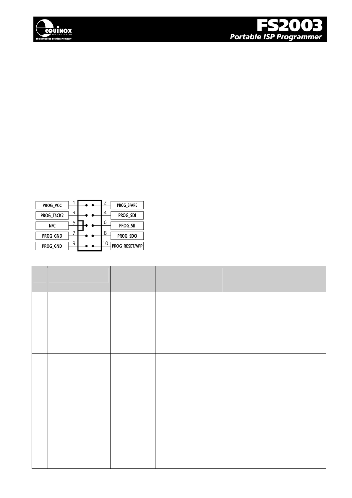
7
4.6 J6(b) - Equinox 10-way Header (ATtiny11/12/15 HV Interface)
This connection method is suitable for interfacing the programmer to a Target System which features
the following:
• Equinox 10-way IDC ISP Header
• An Atmel ATtiny microcontroller eg. ATtiny11/12/15
• Suitable connections to implement ‘High Voltage Serial Programming Mode’.
The connector supports programming of the Atmel ATtiny11/12/15 microcontrollers in ‘High Voltage
Serial Programming Mode’. This mode requires that a +12.0V Vpp voltage is applied to the RESET
pin of the target device in order to enter programming mode.
To implement this connection, simply plug the 10-way ISP cable into the Programmer J6 header and
plug the other end of the cable into the matching header on the Target System. Please ensure that
you have made the correct connections from the ISP Header to your Target Device.
Figure 4.6.1 – Equinox 10-way IDC Header (J8) viewed from above
Warning!
3. It is possible for +12V to be output on pin 10 of this
connector when programming ATtiny11/12/15 devices.
4. Connecting to the wrong ISP Header may cause
catastrophic damage to the Programmer & Target
Pin
Programmer
No
Pin name
1 PROG_VCC P TARGET_VCC Target VCC
2 PROG_SPARE - No connect Spare Programmer I/O pin
Programmer
Input /
Output
System
Connect to
pin on
Target Device
Description
This pin should be connected to
the Target System Vcc. This
voltage could be used to power
the programmer depending on the
settings of the power
switch/jumper on the programmer.
This pin is currently a I/O spare pin
which is not used during SPI
programming. In order to use this
pin, the pin state must be setup in
the EQTools <Pre-programming
State Machine> tab.
3 PROG_TSCK2 O XTAL1
FS2003 ISP Programmer - User Guide V1.07 – 1st September 2007 6
SCK2 Clock Output
This output pin is used to supply
an external clock signal (SCK2) to
the target microcontroller.
Page 71
4 PROG_SDI O SDI
5 N/C O N/C Not connected
6 PROG_SII O SII SII (Serial Instruction Input)
7 PROG_GND P GROUND Ground Connection
8 PROG_SDO I SDO SDO (Serial Data Output)
Serial Data Input
This is the serial data output pin
from the programmer. This pin
should be connected to the Serial
Data Input (SDI) pin on the Target
Microcontroller.
This is the serial data input pin to
the programmer from the Target
Device. This pin should be
connected to the SII pin on the
Target Microcontroller.
Common ground connection
between PROGRAMMER and
Target System.
This is the serial data output signal
from the Target Device to the
programmer. It is an INPUT pin to
the programmer.
9 PROG_GND P GROUND Ground Connection
Common ground connection
between PROGRAMMER and
Target System.
10 PROG_RESET/VPP O RESET Target RESET control pin
This pin controls the Target Device
RESET pin. A +12.0V Vpp voltage
will be applied to this pin during
programming.
Warning!
During ‘High Voltage Serial
Programming’ of the Atmel
ATtiny11/12/15 microcontrollers, a
+12V Vpp voltage is generated by
the programmer on this pin.
Key
O - Output from programmer to Target Device
I - Input to programmer from Target Device
P - Passive eg. GROUND and power rails
N/C - Not connected
FS2003 ISP Programmer - User Guide V1.07 – 1st September 2007 68
Page 72
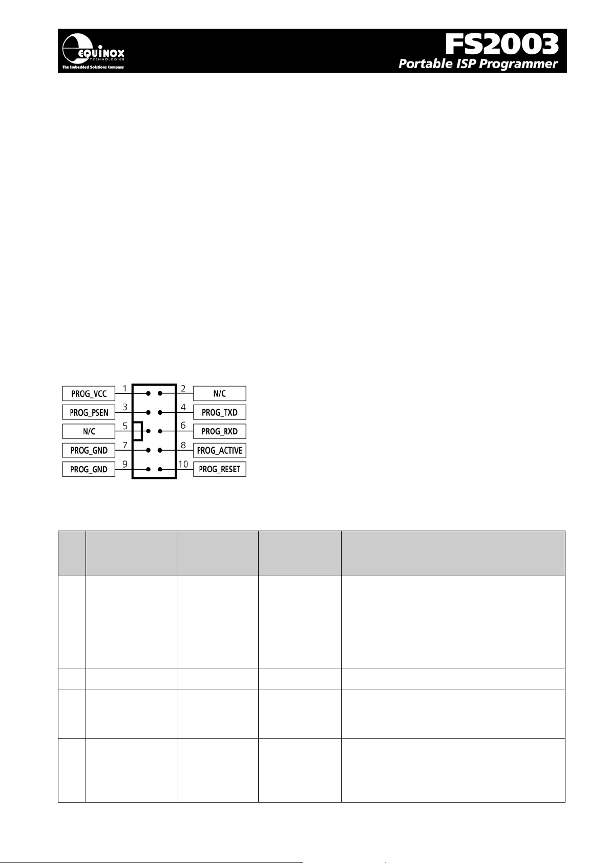
4.7 J6(c) - Equinox 10-way Header (UART Boot Loader)
This connection method is suitable for interfacing the FS2003 programmer to a Target System which
features the following:
• Equinox 10-way IDC ISP Header
• An Atmel Wireless T89C51Rx2 / CC01 microcontroller
• A Philips P89C51Rx2 or P89C66x microcontroller
• The relevant connections for in-system programming via the Boot Loader.
To implement this connection, simply plug the 10-way ISP cable into the Programmer J6 header and
plug the other end of the cable into the matching header on the Target System.
Please note:
The programmer interfaces to the Target System at TTL voltage levels. If the serial port to your Target
System is RS-232, you will need to convert the TTL levels from the programmer to RS-232 using an
external convertor.
Figure 4.7.1 – Equinox 10-way IDC Header (J8) viewed from
above
Warning!
1. It is possible for +12V to be output on pin 10 of this
connector when programming ATtiny11/12/15
devices.
2. Connecting to the wrong ISP Header may cause
catastrophic damage to the Programmer & Target
System
Pin
Programmer
No
Pin name
1 PROG_VCC P TARGET_VCC Target Vcc
2 N/C - N/C Not connected
3 PROG_PSEN O PSEN PSEN pin
Programmer
Input / Output
Connect to
pin on
Target Device
Description
This pin should be connected to the Target
System Vcc. This voltage could be used to
power the programmer depending on the
settings of the power switch/jumper on the
programmer.
This pin is driven LOW by the programmer
to enter ‘Boot Loader’ programming mode.
4 PROG_TXD O RXD Programmer RXD (Transmit) pin
The programmer transmits serial data on
this pin to the Target Device RXD
(Receive) pin.
FS2003 ISP Programmer - User Guide V1.07 – 1st September 2007 69
Page 73
5 N/C - N/C Not Connected
6 PROG_RXD I TXD Programmer RXD (Transmit) pin
The programmer receives serial data on
this pin from the Target Device TXD
(Transmit) pin.
7 PROG_GND P Ground
Connection
Target / Programmer GROUND
connection
Common ground connection between
PROGRAMMER and Target System.
8 PROG_ACTIVE O LED or
Interrupt pin
Programmer ACTIVE LED
This pin can be driven LOW when a
programming action is taking place. The
signal can be used to illuminate an LED or
trigger an interrupt on the Target
Microcontroller.
9 PROG_GND P Ground
Connection
Target / Programmer GROUND
connection
Common ground connection between
PROGRAMMER and Target System.
10 PROG_RESET O RESET Target RESET control pin
This pin controls the Target Device RESET
pin. It will driven HIGH/LOW according to
the device type and settings in the ‘Preprogram State Machine’ tab in the Eqtools
project.
Warning!
During ‘High Voltage Serial Programming’
of the Atmel ATtiny11/12/15
microcontrollers, a +12V Vpp voltage is
generated by the programmer on this pin.
Key
O - Output from programmer to Target Device
I - Input to programmer from Target Device
P - Passive eg. GROUND and power rails
N/C - Not connected
FS2003 ISP Programmer - User Guide V1.07 – 1st September 2007 70
Page 74
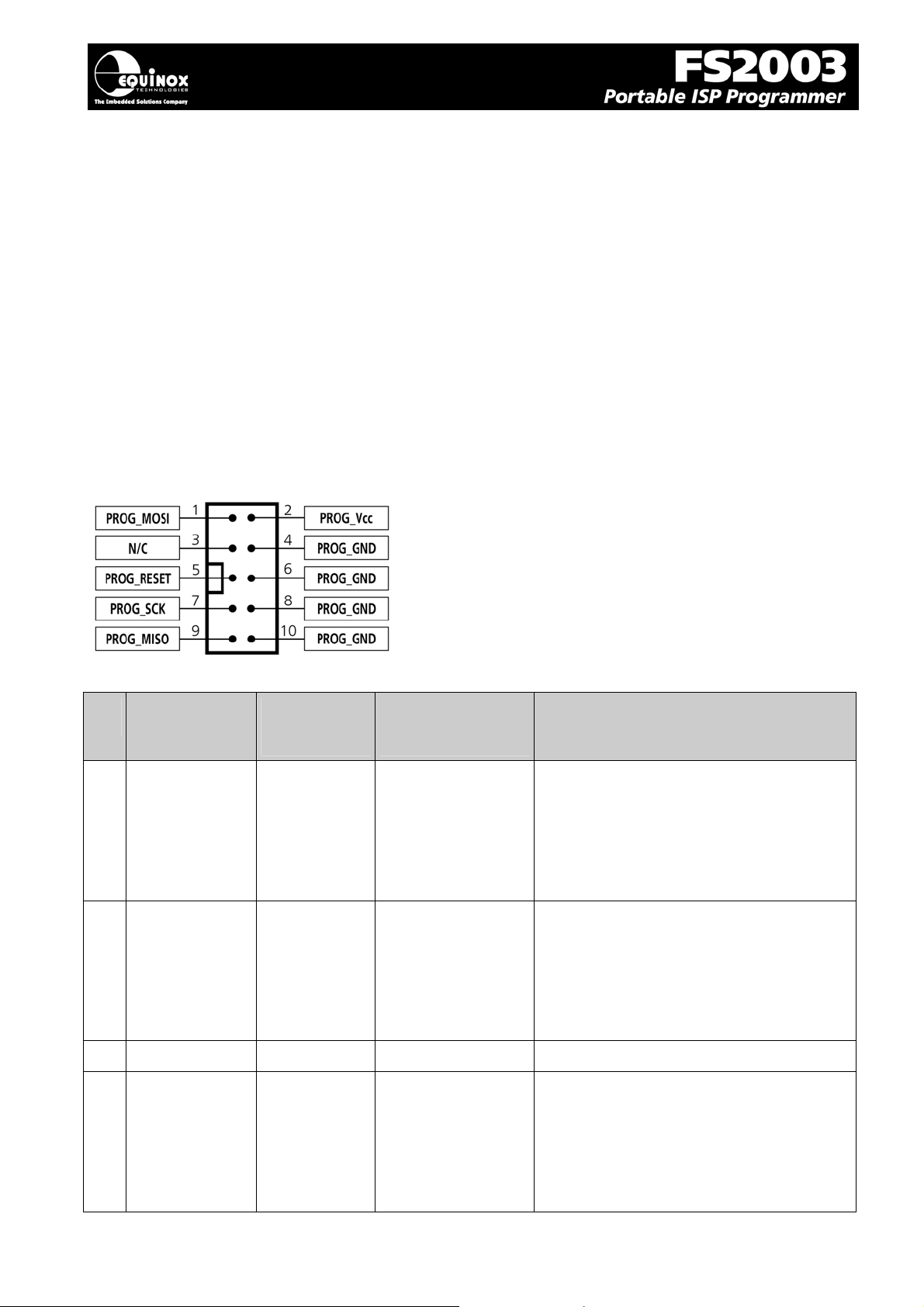
4.8 J7 - Atmel 10-way Header (SPI Interface)
A
This connection method is suitable for interfacing the programmer to a Target System which features
the following:
• Atmel 10-way IDC ISP Header
• An Atmel device which features the 3-wire SPI + RESET Programming Interface
This connector is compatible with the Atmel STK200, STK300 and STK500 Starter Kits. Equinox
would recommend not using this connector on new designs, but instead using the ‘Equinox 10-way
Header’ as the Equinox header caters for an External Oscillator, Vpp switching and also features a
spare I/O pin for future expandability.
To implement this connection, simply plug the 10-way ISP cable into the Programmer ISP Header J7
and plug the other end of the cable into the matching header on the Target System.
Figure 4.8.1 - Atmel 10-way IDC Header (J7) viewed from above
Warning!
Connecting to the wrong ISP Header may cause
catastrophic damage to the Programmer & Target System
Pin
Pin name Programmer
No
1 PROG_MOSI-1 O MOSI
2 PROG_VCC P TARGET_VCC Target Vcc
3 N/C - N/C Not connected
4 PROG_GND P GROUND Ground Connection
Input /
Output
Connect to
pin on
Target Device
(except for
Tmega103/128/64
– connect to RXD
pin instead)
Description
Master Out Slave In
This is the SPI data output pin from the
programmer. This pin should be
connected to the MOSI pin on the Target
Microcontroller.
This pin should be connected to the
Target System Vcc. This voltage could
be used to power the programmer
depending on the settings of the power
switch/jumper on the programmer.
Common ground connection between the
programmer and Target System.
FS2003 ISP Programmer - User Guide V1.07 – 1st September 2007 71
Page 75
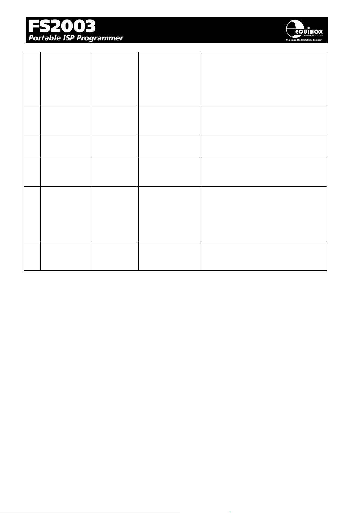
5 PROG_RESET O RESET Target RESET control pin
A
This pin controls the Target Device
RESET pin. It will be driven HIGH/LOW
according to the device type and settings
in the ‘Pre-program State Machine’ tab in
the Eqtools project.
6 PROG_GND P GROUND Ground Connection
Common ground connection between the
programmer and Target System.
7 PROG_SCK1 O SCK SPI Serial Clock Output
This is the SPI clock output signal.
8 PROG_GND P GROUND Ground Connection
Common ground connection between the
programmer and Target System.
9 PROG_MISO I MISO
(except for
Tmega103/128/64
– connect to TXD
Master In Slave Out
This is the SPI data input pin to the
programmer. This pin should be
connected to the MISO pin on the Target
Microcontroller.
pin instead)
10 PROG_GND P GROUND Ground Connection
Common ground connection between
PROGRAMMER and Target System.
Key
O - Output from programmer to Target Device
I - Input to programmer from Target Device
P - Passive eg. GROUND and power rails
N/C - Not connected
FS2003 ISP Programmer - User Guide V1.07 – 1st September 2007 72
Page 76
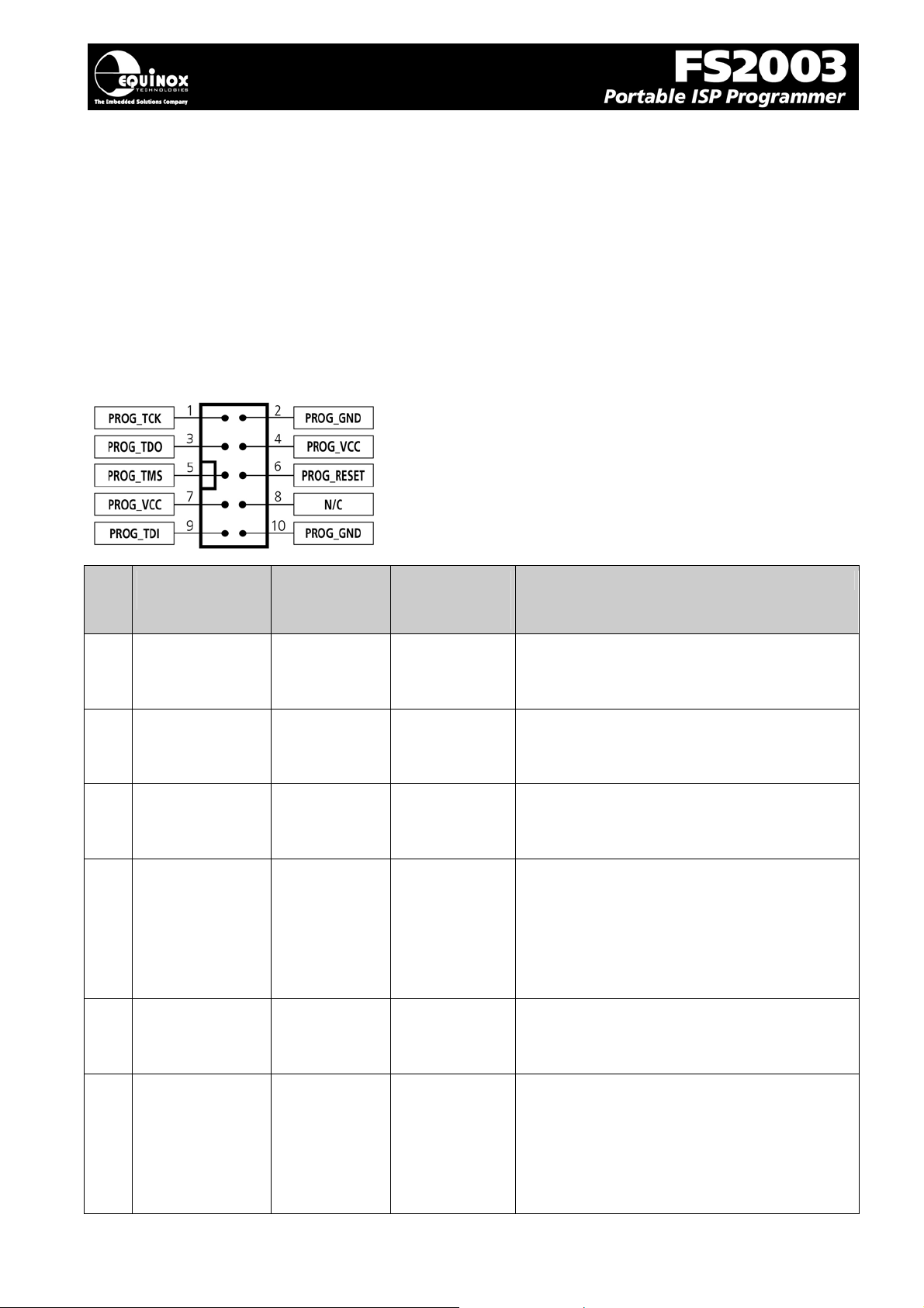
4.9 J8 - Atmel 10-way JTAG Header (JTAG Interface)
This connection method is suitable for interfacing the programmer to a Target System which features
the following:
• An Atmel device which features a JTAG ISP port e.g. ATmega128 / 323 / 64
• Atmel 10-way IDC JTAG Header
• This is the same header as used on the Atmel JTAG-ICE emulator.
To implement this connection, simply plug the 10-way ISP cable into the Programmer ISP Header J8
and plug the other end of the cable into the matching header on the Target System.
Figure 4.9.1 - Atmel 10-way IDC Header (J8) viewed from
above
Warning!
Connecting to the wrong ISP Header may cause
catastrophic damage to the Programmer & Target
System
Pin
No
1 PROG_TCK O TCK JTAG TCK – Test Clock Signal pin
2 PROG_GND P GROUND Ground Connection
3 PROG_TDO I TDO JTAG TDO – Test Data Output pin
4 PROG_VCC P TARGET_VCC Target Vcc Connection
5 PROG_TMS O TMS JTAG TMS – Test Mode Select pin
Programmer
Pin name
Programmer
Input /
Output
Connect to
pin on
Target Device
Description
Clock signal from programmer to Target
Device JTAG port.
Common ground connection between
Programmer and Target System.
Data signal from Target device JTAG port
to programmer.
- Pins 4 + 7 are physically connected
inside the programmer.
- Connects to Vcc rail of Target System.
- Pin referred to as VTref on Atmel JTAGICE.
Mode Select Signal from programmer to
Target Device JTAG port.
6 PROG_RESET O RESET Microcontroller RESET control signal
This pin connects to the main RESET pin
of the Target Microcontroller. This pin is
not strictly needed for JTAG programming,
but it can be used to RESET the Target
Device before and after programming.
FS2003 ISP Programmer - User Guide V1.07 – 1st September 2007 73
Page 77
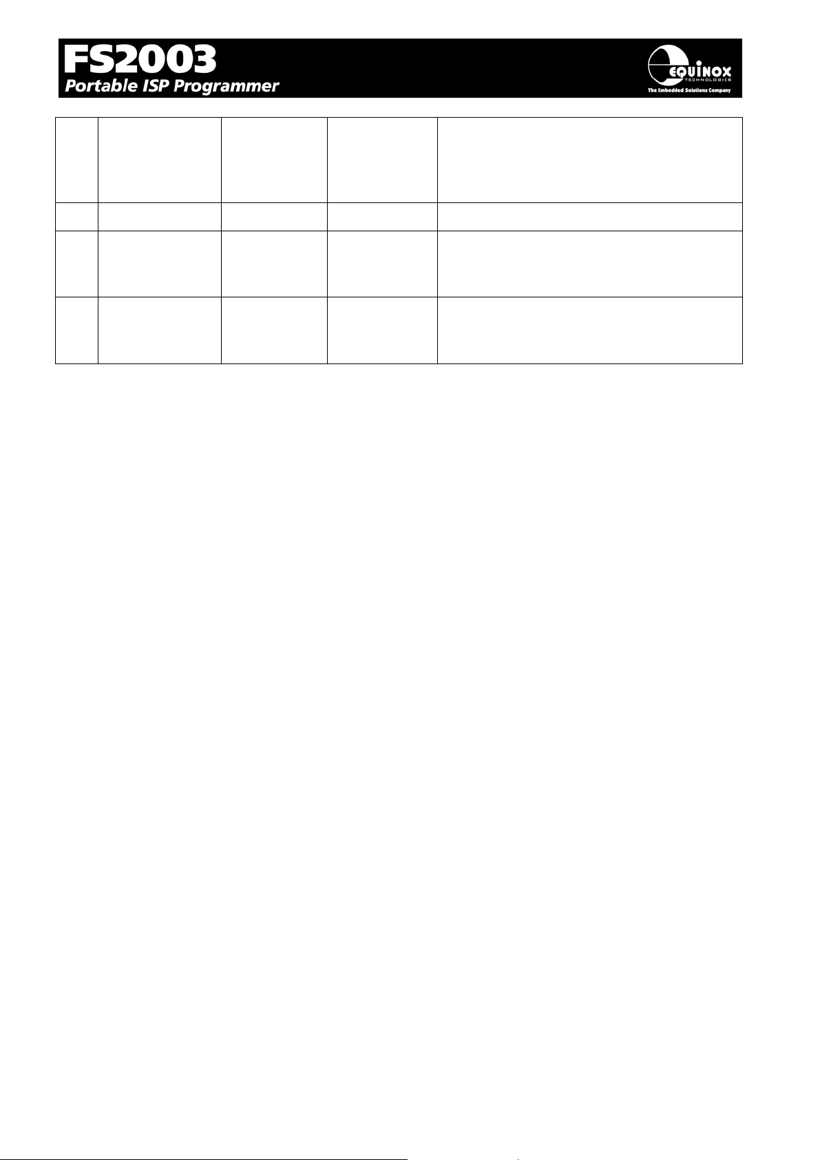
7 PROG_VCC P TARGET_VCC Target Vcc Connection
- See pin 4
- Pins 4 + 7 are physically connected
inside the programmer.
8 N/C O N/C Not Connected
9 PROG_TDI O TDI JTAG TDI – Test Data Input pin
Data signal from programmer to Target
Device JTAG port.
10 PROG_GND P GROUND Ground Connection
Common ground connection between
PROGRAMMER and Target System.
Key
O - Output from programmer to Target Device
I - Input to programmer from Target Device
P - Passive eg. GROUND and power rails
N/C - Not connected
FS2003 ISP Programmer - User Guide V1.07 – 1st September 2007 74
Page 78
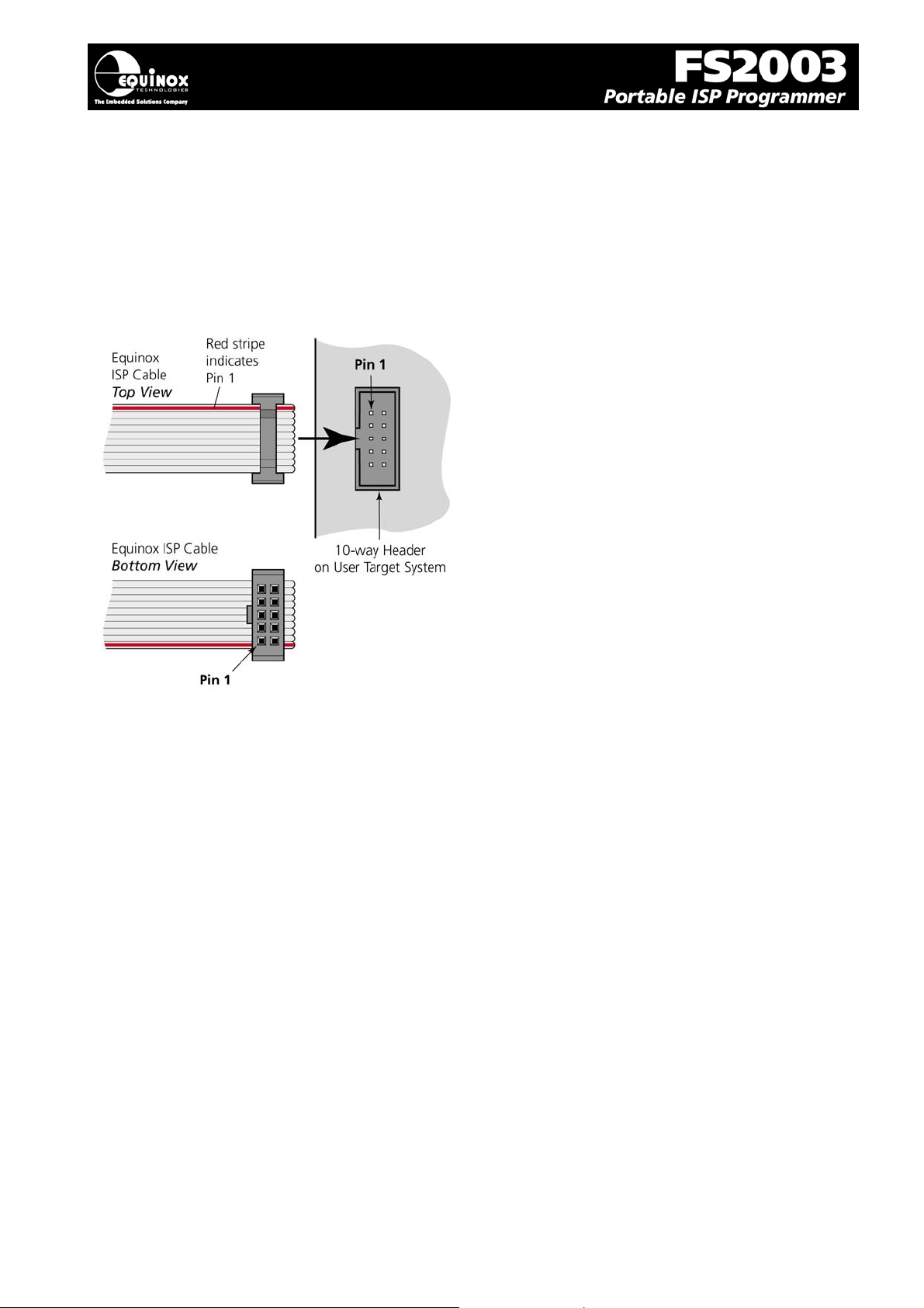
5
4.10 ISP Cable considerations
The programmer is supplied with a single 10-way ISP Cable as standard. This cable is terminated
with a 10-way IDC 0.1” female polarised plug at each end. The cable is wired as a so-called ‘straightthrough’ cable with pin 1-1, 2-2 etc. The polarised ISP Header ensures that the ISP Cable cannot be
plugged in the wrong way around by mistake. If you are planning to design such a header onto your
Target System, it is strongly recommended that a similar polarised header is used. This will help to
prevent accidental damage to both the programmer and the Target System.
Pin 1 of the ISP cable can be determined by looking for a small arrow on the plastic part of the ISP
female plug. If the cable has a RED stripe on one cable, this usually also indicates pin 1.
If you are using the programmer in a production environment and constantly plugging / unplugging the
ISP cable into/from the Target System, you may find that the cable eventually fails. Spare ISP cables
can be ordered from Equinox in this eventuality.
FS2003 ISP Programmer - User Guide V1.07 – 1st September 2007 7
 Loading...