

Page 1
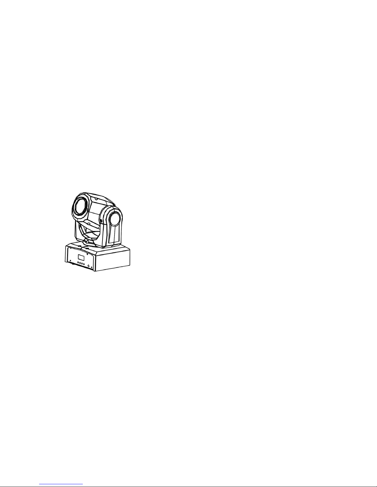
EQUINOX
FUSION SPOT
User Manual
EQLED008/EQLED008A
Contents
1. Safety Instructions
2. Features & Specifications
3. How To Set The Unit
4. Troubleshooting
5. Fixture Cleaning
Page 2
1. Safety Instruction
WARNING
Please keep this User Guide for future consultation. If you sell the unit to
another user be sure that they also receive this.
Unpack and check carefully that there is no transportation damage before
using the unit.
Before operating, ensure that the voltage and frequency of the power
supply match the power requirements of the unit.
It’s important to ground the yellow/green conductor to earth in order to
avoid electric shock.
The unit is for indoor use only. Use only in a dry location.
The unit must be installed in a location with adequate ventilation, at
least 50cm from adjacent surfaces. Be sure that no ventilation slots are
blocked.
Disconnect the mains power before replacement or servicing.
Make sure there are no flammable materials close to the unit while
operating as they may cause a fire hazard.
Always use a safety cable when installing this unit. Do not carry the unit
with its head only, always carry it using the base.
The maximum ambient temperature is: 40℃. Don’t operate it where the
temperature is higher than this.
In the event of a serious operating problem stop using the unit
immediately. Never try to repair the unit by yourself. Repairs carried out
by unskilled people can lead to damage or malfunction. Please contact
the nearest authorized technical assistance center. Always use the
same type spare parts.
Do not touch any power cables during operation as the high voltage
may cause an electric shock.
Warning
To prevent or reduce the risk of electrical shock or fire, do not expose
the unit to rain or moisture.
Do not open the unit within five minutes after switching off.
The housing and lenses must be replaced if they are visibly damaged.
Installation
The unit should be mounted via its screw holes onto the bracket. Always
ensure that the unit is firmly fixed to avoid vibration and slipping while
operating. Make sure that the structure to which you are attaching the
unit to is secure and is able to support a weight of 10 times of the unit’s
weight. Always use a safety cable that can hold 12 times of the weight of
the unit when installing the fixture.
The equipment must be installed by professionals and it must be
installed in a place where is out of the reach of people and no one can
pass by or under it.
2. Features & Technical Specifications
◇ Control: Sound active, Auto, Master/slave and DMX-512 modes
◇ DMX Channels: 1CH/8CH/10CH
◇ Gobos: 7 Gobos + open
◇ Colors: 7 Colors + Open
◇ Electronic dimming: 0-100%
◇ Compact size and light-weight
Please read the instructions carefully as they include
important information about installation, usage and
maintenance.
Page 3
3. How To Set The Unit
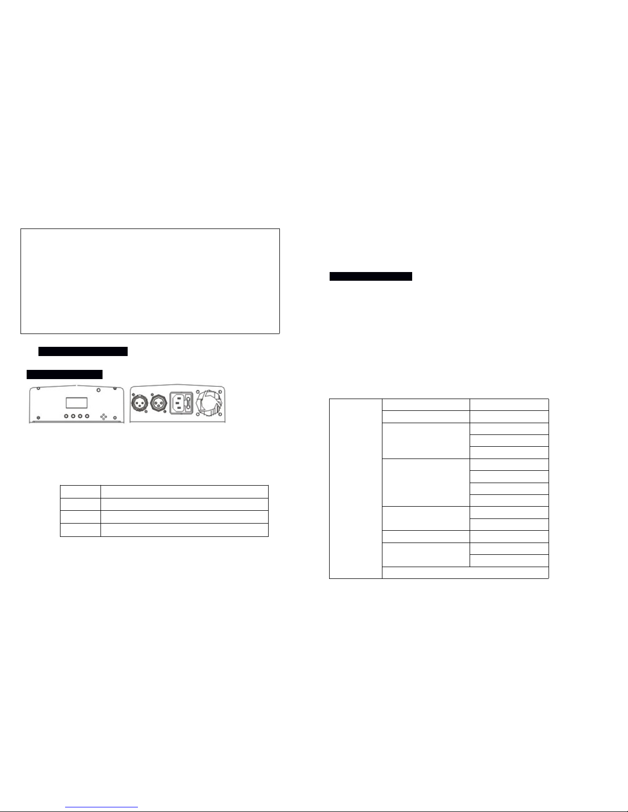
3.1 Control panel
Display
Shows the various menus and selected functions
Button
MENU Selects the programming functions
DOWN To go backward in the selected functions
UP To go forward in the selected functions
ENTER Confirms the selected functions
Mains input
Connection to the power supply.
DMX input/output
For DMX 512 linking. Use a 3-pin XLR cables to link to the controller or to
other units.
3.2 Main Functions
To select any of the given functions, press the MENU button up to where
the required function is showing on the display. Select the function by
pressing the ENTER button and the display will blink. Use the DOWN and
UP buttons to change the mode. Once the required mode has been
selected, press the ENTER button to confirm. To go back to the functions
without any changes, press the MENU button again. Press and hold the
MENU button for one second or wait for one minute to go back to the
main menu.
The main functions are as below:
Menu
ADDR 001-512
CHND 1CH/8CH/10CH
SLMD
MAST
SL1
SL2
SHND
SH1
SH2
SH3
SH4
SOUN
ON
OFF
SENS 000-100
LED
ON
OFF
DISP→INVERT
Voltage: 100V~240V, 50/60Hz
Fuse: T 2.5A
Power consumption: 27W
Light source: 1 x 12W white LED
Dimension: 159 x 147 x 265mm
Weight: 2.5 kg
Pan/Tilt: 540°/270°
Power sockets: IEC IN
XLR sockets: 3-pin XLR IN/OUT
Page 4
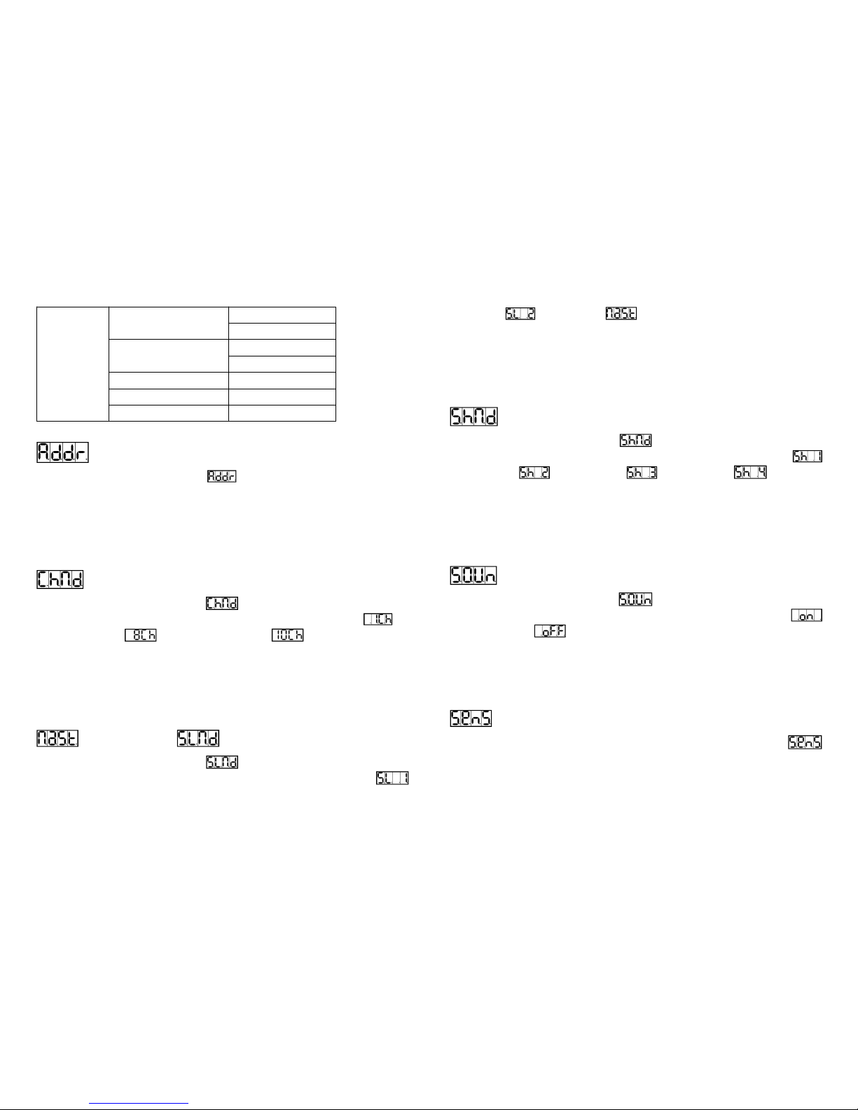
PAN INVERT
YES
NO
TILT INVERT
YES
NO
TEST Self-Test
VER Software Version
RSET RSET
DMX Address Setting
Press the MENU button to select . Press the ENTER button and the
display will blink. Use the DOWN and UP buttons to choose the address
to confirm. To go back to the functions without any changes press the
MENU button again. Press and hold the MENU button for one second or
wait for one minute to go back to the main menu.
Channel Mode
Press the MENU button to select . Press the ENTER button and the
display will blink. Use the DOWN and UP buttons to select the (1
Channel) mode, (8 Channel) mode or (10 Channel) mode.
Once the mode has been selected, press the ENTER button to confirm. To
go back to the functions without any changes press the MENU button
again. Press and hold the MENU button for one second or wait for one
minute to go back to the main menu.
Master Mode or Slave Mode
Press the MENU button to select . Press the ENTER button and the
display will blink. Use the DOWN and UP buttons to select the
(Slave 1), (Slave 2) or (Master) mode. Once the mode has
been selected, press the ENTER button to confirm. To go back to the
functions without any changes press the MENU button again. Press and
hold the MENU button for one second or wait for one minute to go back to
the main menu.
Show Mode
Press the MENU button to select . Press the ENTER button and the
display will blink. Use the DOWN and UP buttons to select the
(show 1) or (show 2) or (show 3) or (show 4)
mode. Once the mode has been selected, press the ENTER button to
confirm. To go back to the functions without any changes press the MENU
button again. Press and hold the MENU button for one second or wait for
one minute to go back to the main menu.
Sound Mode
Press the MENU button to select . Press the ENTER button and the
display will blink. Use the DOWN and UP buttons to select the
(sound on) or (sound off) mode. Once the mode has been
selected, press the ENTER button to confirm. To go back to the functions
without any changes press the MENU button again. Press and hold the
MENU button for one second or wait for one minute to go back to the
main menu.
Sound Sensitivity
Press the MENU and use the UP and DOWN buttons to select
and select the sound sensitivity between value 0 and 100. Press the
ENTER button for confirmation after value selection. To go back to the
Page 5
functions without any changes press the MENU button again.
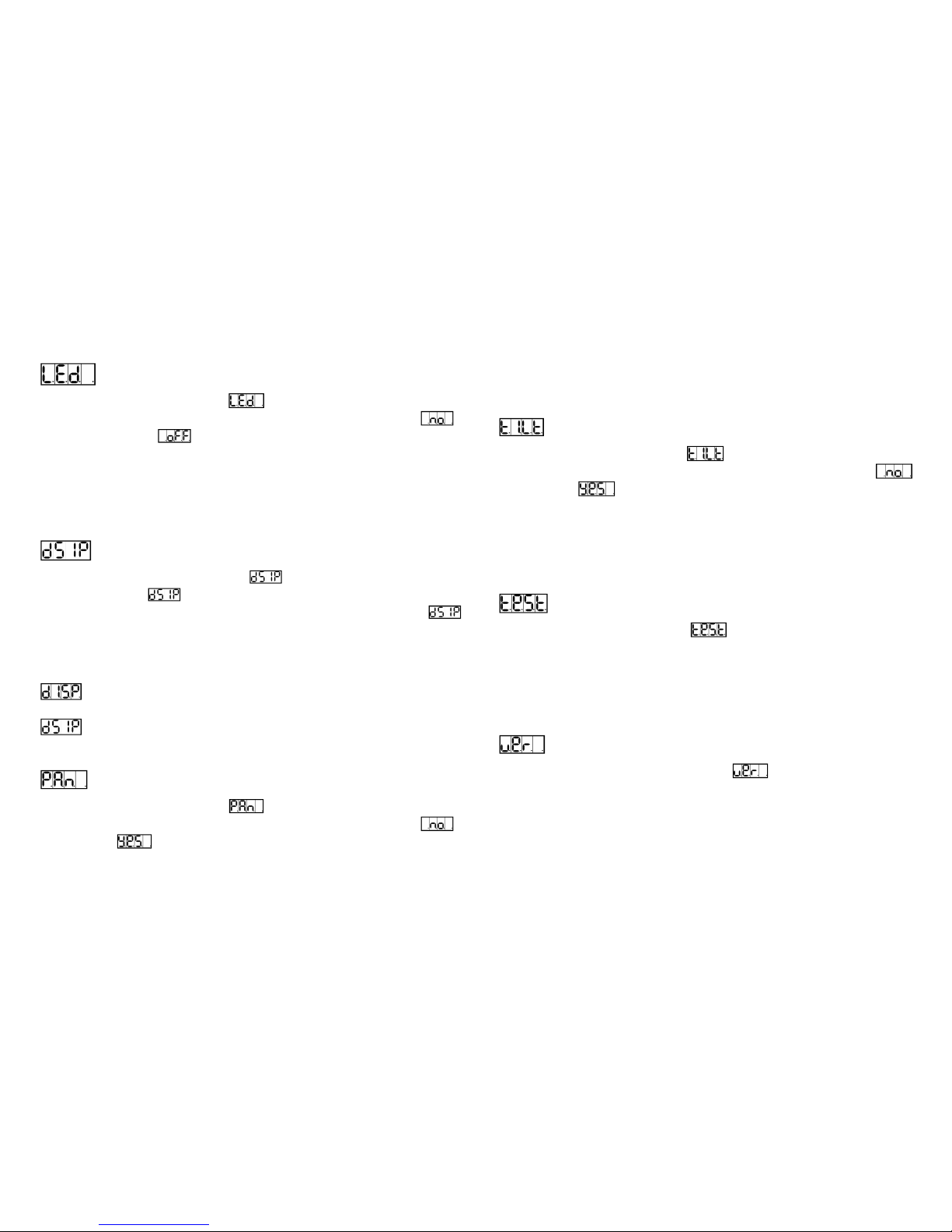
Led Display
Press the MENU button to select . Press the ENTER button and the
display will blink. Use the DOWN and UP buttons to select the
(Led display on) or (Led display off) mode. Once the mode has
been selected, press the ENTER button to confirm. To go back to the
functions without any changes press the MENU button again. Press and
hold the MENU button for one second or wait for one minute to go back to
the main menu.
Display Inversion
Press the MENU button to select . Press the ENTER button to
change the mode (display normal), it will be automatically saved
after 8 seconds. Press the ENTER button again to select the mode
(display inversion). To go back to the functions press the MENU button.
Press and hold the MENU button for one second or wait for one minute to
go back to the main menu.
Display normal mode is for floor standing the unit.
Display inversion mode is for hanging the unit upside down.
Pan Inversion
Press the MENU button to select . Press the ENTER button and the
display will blink. Use the DOWN and UP buttons to select the
(normal) or (pan inversion) mode. Once the mode has been
selected, press the ENTER button to confirm. To go back to the functions
without any changes press the MENU button again. Press and hold the
MENU button for one second or wait for one minute to go back to the
main menu.
Tilt Inversion
Press the MENU button to select . Press the ENTER button and the
display will blink. Use the DOWN and UP buttons to select the
(normal) or (tilt inversion) mode. Once the mode has been
selected, press the ENTER button to confirm. To go back to the functions
without any change press the MENU button again. Press and hold the
MENU button for one second or wait for one minute to go back to the
main menu.
Auto-Test
Press the MENU button to select . Press the ENTER button and the
unit will run a self-test with its built-in programs. To go back to the
functions without any changes press the MENU button again. Press and
hold the MENU button for one second or wait for one minute to go back to
the main menu.
Software version
Press the MENU button up to when the is blinking on the display.
Pressing ENTER button and the display will show the version of software of
the unit. To go back to the functions press the MENU button.
Page 6
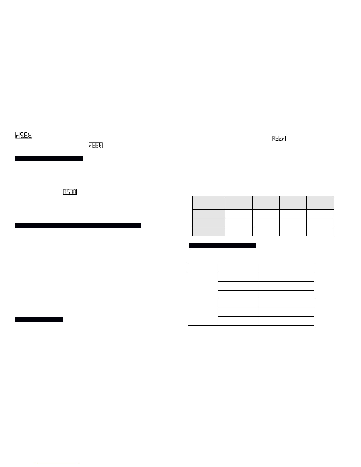
Reset
Press the MENU button to select . Press the ENTER button and all
channels of the unit will return to their standard position.
4. How To Control The Unit
1. Master/slave built-in preprogram function
2. Universal DMX controller
There is no need to turn the unit off when you change the DMX address as
new DMX address setting will take effect at once. Every time you turn the
unit on, it will show “ ”on the display and move all the motors to
their ‘home’ position and you may hear some noises for about 20 seconds.
After that the unit will be ready to receive a DMX signal or run the built in
programs.
4.1 Master/Slave Built In Preprogrammed Function
By linking the units in master/slave connection, the first unit will control
the other units to give an automatic, sound activated, synchronized light
show. This function is good when you want an instant show. You have to
set the first unit as master and select show 1, show 2, show 3 or show
4 from the Show Mode. The other unigts must be set to either Slave 1
(normal) or Slave 2 (2 light show) mode. A DMX cable between the units
for daisy chaining is needed.
2-light show
In slave mode, Slave 1 means the unit works normally and Slave 2
means 2-light show. In order to create a great light show, you can set
Slave 2 on the second unit to get contrast movement to each other, even
if you have two units only.
4.2 DMX Controller
By using a universal DMX controller to control the units, you will need to
set a DMX address from 1 to 512 so that the units can receive a DMX
signal. Press the MENU button until is showing on the display.
Press the ENTER button and the display will blink. Use the DOWN and
UP buttons to change the DMX-512 address. Once the address has been
selected, press the ENTER button to confirm. To go back to the functions
without any changes press the MENU button again. Press and hold the
MENU button one second or wait for one minute to go back to the main
menu.
Please refer to the below diagram to address your first 4 units:
Channel
mode
Unit 1
Address
Unit 2
Address
Unit 3
Address
Unit 4
Address
1 channel 1 2 3 4
8 channel 1 9 17 25
10 channel 1 11 21 31
4.3 DMX 512 Configuration
1 CHANNEL MODE
Channel
Function Value
1
Random shows 248-255
Show 4 188-247
Show 3 128-187
Show 2 068-127
Show 1 008-067
Blackout 000-007
Page 7
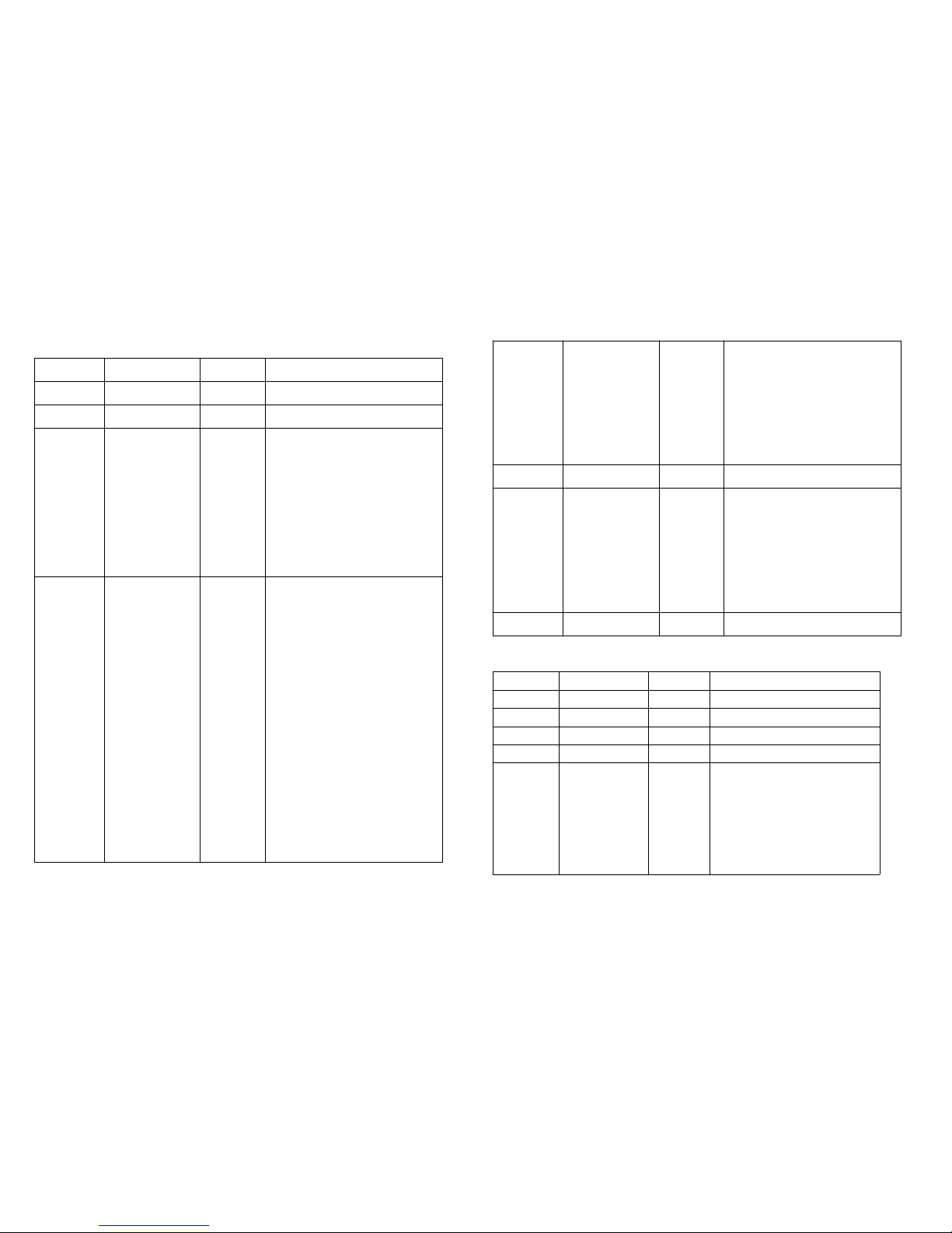
8 CHANNEL MODE
Channel
Function Value Percent / Setting
1
Pan 000-255 0~100%
2 Tilt 000-255
0~100%
3
Color
000-007
008-014
015-021
022-028
029-035
036-042
043-049
050-056
057-127
128-189
190-193
194-255
White
Light Blue
Pink
Orange
Green
Blue
Yellow
Red
Split colors
Color Scroll Fast to Slow
Stop
Color Scroll Slow to Fast
4 Gobo
000-007
008-015
016-023
024-031
032-039
040-047
048-055
056-063
064-071
072-079
080-087
088-095
096-103
104-111
112-119
120-127
128-189
190-193
194-255
120-127
128-189
190-193
194-255
Gobo 1 (Open)
Gobo 2
Gobo 3
Gobo 4
Gobo 5
Gobo 6
Gobo 7
Gobo 8
Gobo 1 Shake
Gobo 2 Shake
Gobo 3 Shake
Gobo 4 Shake
Gobo 5 Shake
Gobo 6 Shake
Gobo 7 Shake
Gobo 8 Shake
Gobo Scroll, Fast to Slow
Stop
Gobo Scroll , Slow to Fast
Gobo 8 Shake
Gobo Scroll, Fast to Slow
Stop
Gobo Scroll , Slow to Fast
5 Shutter
000-007
008-015
016-131
132-139
140-181
182-189
190-231
232-239
240-247
248-255
Close
Open
Strobe Slow->Fast
Open
Fast Close Slow Open
Open
Fast Open Slow Close
Open
Random Strobe
Open
6
Pan/Tilt Speed 000-255 Fast -> Slow
7
Function
000-069
070-079
080-089
090-099
100-109
110-119
120-199
200-209
210-249
250-255
Null
Blackout while Pan/Tilt Move
Null
Blackout when Color changes
Null
Blackout when Gobo changes
Null
Reset All
Null
Sound Active
8 Dimmer 000-255 0~100%
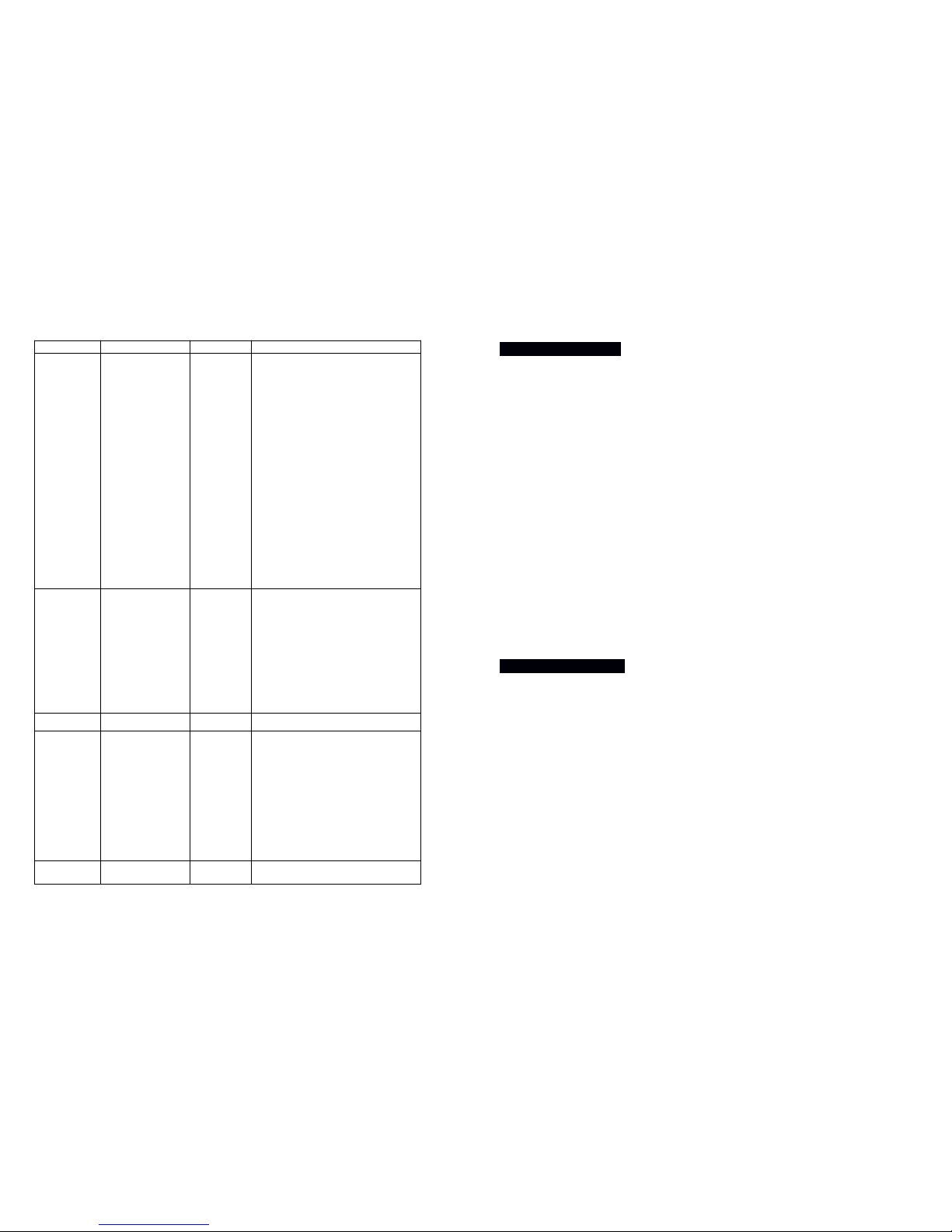
10 CHANNEL MODE
Channel Function Value
Percent / Setting
1 Pan1
000 - 255
Pan 0°~ 540°
2 Pan Fine
000 - 255
Tilt 0°~ 270°
3 Tilt
000-255 0~100%
4 Tilt Fine 000-255 0~100%
5 Shutter
000-007
008-015
016-131
132-139
140-181
182-189
190-231
232-239
240-247
Close
Open
Strobe Slow>Fast
Open
Fast Close Slow Open
Open
Fast Open Slow Close
Open
Random Strobe
Page 8
248-255 Open
6 Gobo
000-007
008-015
016-023
024-031
032-039
040-047
048-055
056-063
064-071
072-079
080-087
088-095
096-103
104-111
112-119
120-127
128-189
190-193
194-255
Gobo 1 (Open)
Gobo 2
Gobo 3
Gobo 4
Gobo 5
Gobo 6
Gobo 7
Gobo 8
Gobo 1 Shake
Gobo 2 Shake
Gobo 3 Shake
Gobo 4 Shake
Gobo 5 Shake
Gobo 6 Shake
Gobo 7 Shake
Gobo 8 Shake
Gobo Scroll, Fast to Slow
Stop
Gobo Scroll , Slow to Fast
7 Shutter
000-007
008-015
016-131
132-139
140-181
182-189
190-231
232-239
240-247
248-255
Close
Open
Strobe Slow->Fast
Open
Fast Close Slow Open
Open
Fast Open Slow Close
Open
Random Strobe
Open
8
Pan/Tilt Speed 000-255 Fast -> Slow
9 Function
000-069
070-079
080-089
090-099
100-109
110-119
120-199
200-209
210-249
250-255
Null
Blackout while Pan/Tilt Move
Null
Blackout when Color changes
Null
Blackout when Gobo changes
Null
Reset All
Null
Sound Active
10
Dimmer
000-255 0~100%
4.Troubleshooting
Following are a few common problems that may occur during
operation and some suggestions for easy troubleshooting:
A. The unit does not work, no light and the fan does not work
1. Check the connection of the power and the main fuse.
B. Not responding to DMX controller
1. DMX LED should be on. If not, check DMX cables to see if linked
correctly.
2. If the DMX address is showing but no response to the controller,
check the address settings and DMX polarity.
3. Try another DMX controller.
C. No response to the sound
1. Make sure the unit is not receiving a DMX signal.
2. Check the microphone to see if it is good by tapping it. The
microphone is located on the bottom plate of the unit.
5. Fixture Cleaning
The cleaning of external optical lenses must be carried out periodically to
optimize light output. Cleaning frequency depends on the environment in
which the fixture operates: damp, smoky or particularly dirty surrounding
can cause a greater accumulation of dirt on the unit’s optics.
Clean with a soft cloth using normal glass cleaning fluid or mild soapy
water.
Always dry the parts carefully.
Clean the external optics at least ev/ery 20 days.
---------------------www.prolight.co.uk----------------------------------
 Loading...