

Equalizer Systems Auto-Level Installation Manual

EQ014R1
(800) 846-9659
equalizersystems.com
Auto-Level Installation-Troubleshooting & Warranty Guide
Effective August 2011
Revision- March 2017
CONTENTS
Required Tools & Parts
Installation
Manifold & Connections
Hydraulic Fluid & Purging
Operation / Manual & AutoLevel
Setting the Null
Helpful Hints
Panel Indicators
Manual Override
Troubleshooting
Warranty
Diagrams
Page 2
Page 3
Page 4
Page 6
Page 8
Page 9
Page 10
Page 11
Page 12
Page 15
Page 17
Appendix

Equalizer Systems Auto-Level Installation Guide
This manual is intended to be used by technicians installing Equalizer Systems
Auto-Level systems. It is assumed that the reader is familiar with hydraulic,
mechanical, and electrical systems; in addition to workplace safety.
Tools Required for Installation
* Note: These items must be # 2 AWG if cable run is greater than 12 ft.
Ratchet, sockets and wrench set
Wire cutters / crimpers
Electric drill and bits
Screw gun bits
Welding equipment (if welding leg or bracket in place)
Additional Items Required for Installation
# 4 AWG power wire (to connect battery +12V positive to the pump)*
# 4 AWG ground wire (to connect battery -12V ground to pump)*
# 4 AWG ring terminals
Loom clips (to secure harnesses and hydraulic hoses to the coach)
Self tapping screws or pop rivets
Wire ties
10 - 16 quarts Dexron Automatic Transmission Fluid
Modification of any factory-supplied item may result in the denial of all warranty claims. Call
Equalizer Systems Technical Support prior to any modifications.
With any hydraulic application, holding position on a cylinder must be done with safety in mind.
Failure in the system may cause the jack(s) to retract or extend suddenly. When working under or
near the coach, always use jack stands of appropriate rating to support the weight of the coach.
2
Installation
Step 1: Determine where the jacks will be mounted. The jacks must be mounted to the chassis
frame, as close as possible to the front and rear axle's.
Step 2 (Jacks): Secure the jack brackets in place with c-clamps and weld the brackets to the frame.
Bolt the jack to the bracket using washers on the bolt head and the nut. The jacks must be installed
with a minimum of 7 to 8 inches of ground clearance. See Installation chart below. In any case, the
bottom of the footpad should be no lower than any other item mounted on the coach. Pay particular
attention to the angle of departure for the chassis when mounting the rear jacks- and the angle of
approach when mounting the front jacks.
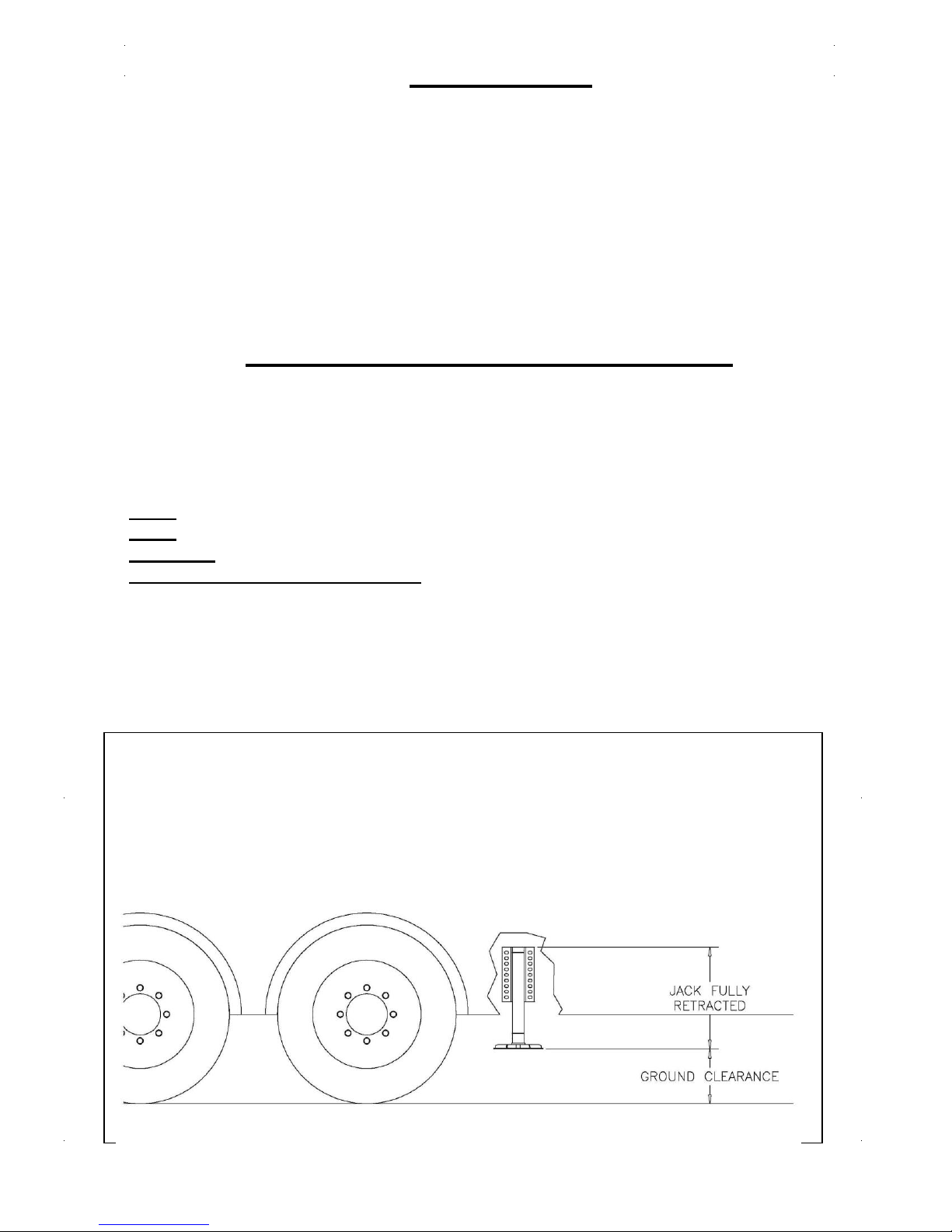
Reference Chart for Installing Jack Legs
The foot / pad must be mounted with-in the range suggested (see chart below) for proper operation of
the system. Retract the jack leg fully (jack leg up); Ground clearance is determined by measuring
from the bottom of the jack foot to the ground (jack retracted fully). When in doubt call Equalizer
Systems 1-800-846-9659 ext: 339
SL-15 = 8 - 10 inches of ground clearance
SL-16 = 8 - 10 inches of ground clearance
SL / DP-18 = 10 – 12 inches of ground clearance
AJ / AM / CT / SM -16, 20, 24, 30, 36
Jack travel (stroke)
16” = 8 - 10inches of ground clearance
20” = 12 - 14 inches of ground clearance
24” = 14 - 16 inches of ground clearance
30” = 16 - 18 inches of ground clearance
36” = 18 - 20 inches of ground clearance
3

Step 3 (Pump): Install the pump kit on the coach. The pump must be mounted in a location that is
reasonable to route all of the hydraulic hoses to the manifold. It must be accessible for filling the
reservoir and monitoring the fill level. Take note if the unit is equipped with the manual override
option. The pump handle, cartridge valves and directional valves must be accessible to manually
override the system. If the pump is equipped with the manual override screw on the end of the motor,
than be sure to allow access to that side of the pump. In most applications, a side storage
compartment will provide the ideal location. An additional mounting box or tray may be used on
other style coaches.
Step 4 (Fittings): Install the hydraulic adaptor fittings in the top and bottom of each jack and
install the fittings into the manifold. The straight thread o-ring side always goes to the cylinder or
manifold. The tapered side will get the hose attached to it. When installing straight fittings into the
leg or manifold, tighten to 15 lbs-ft. When using 90 degree fittings, turn until finger tight, position
correctly, then tighten the jam nut to 15 lbs-ft.
Step 5 (Hoses): Install the hydraulic hoses according to the chart below. Route the hoses clear of
all hot exhaust components and pinch points in the suspension/chassis system. Attach the hoses to
the manifold and jack fittings (from step 4). Tighten to 15 lbs-ft. Secure the hydraulic hoses with
wire ties or loom clamps to the chassis.
Care should be taken to not kink or twist hoses. The minimum bend radius is 6 inches.
Installation of Hoses to the Manifold
Jack Leg
Left Front-TOP
Left Front-BOTTOM
Right Front-Top
Right Front Bottom
Left Rear-Top
Left Rear-Bottom
Right Rear-Top
Right Rear-Bottom
Manifold Connection
T-1 Brown Solid
B-1 Brown Stripe
T-2 White Solid
B-2 White Stripe
T-3 Orange Solid
B-3 Orange Stripe
T-4 Yellow Solid
B-4 Yellow Stripe
4

Connections: Keypad / Controller / Pump Assembly
Step 6: Mount the Controller- Equalizer Part # 2730, 2745 or 2755 (Depending on the
application). The controller must be mounted near to the center of the “X” that the jack legs form. It
must be mounted to the underside of the floor or to a frame or cross member that “reacts” with the
coach as the jacks plant and lift the coach. All 4 mounting holes in the mounting plate must be used.
There is a sticker on the controller indicating “UP and “Front”. It is imperative that the controller be
mounted according to this sticker. Keep the controller away from high heat sources or moving
objects.
Step 7 (Keypad): Fasten the keypad mount in the desired location
applicable). Attach the supplied wire harness between the keypad and the location of the controller
(see step 3 above). This harness will connect the in-board 4-pin (J-1) connector on the keypad, and
the mating connector on the controller. This 4 pin connector is the only connection made to the
keypad.
Secure the harness with wire ties or loom clamps to the chassis. Refer to the attached diagram.
Chassis interface connections: Please note that Step 8 and 9 are
required. Step 10 is optional.
Step 8 (Keypad Ignition Disable Circuit): Note the “break-outs" near the end of the keypad
harness. The Pink wire must receive a +12 VDC Input when the ignition key is in the “on” position.
Connect this wire to the ignition positive. This will make the wire "hot” and will inhibit jack
extension when the vehicle ignition key is in the on (engine run) position. This also provides for a
“jacks down” warning in the event of a jack drifting from the stowed position during travel. This
connection is required. Failure to make this connection may create an unsafe condition and may void the
warranty.
Step 9 The Black w/ Yellow wire must receive a Ground Input. This Black w/ Yellow wire
must be connected to a chassis ground. If this wire is not connected to ground the Engage Park Brake
light will be on and AutoLevel will be Denied.
Optional Park Brake Connection for Black/yellow wire:
Contact your chassis manufacturer to verify park brake chassis connection and location. This
connection must be done by a technician qualified for chassis electrical systems. Most chassis
manufactures are now doing this thru the Dash Module. Attempts to connect this improperly could
lead to dash feed back or other issues. This connection to a park brake signal is optional. If this input
is not connected to the park brake signal or to ground, AUTO-LEVEL will be continuously denied.
Also, the engage park brake light will be on if the panel is powered up or the key is in the on (engine
run position).
*Note on items 8 and 9: If Black/Yellow is connected to a park brake signal (as in step 9)
and the pink is connected (required) as in Step 8, an automatic “all retract” will be initiated
if the key is turned on (engine run position) and the park brake is released.
Step 10 (Suspension deflate/Inflate): If chassis is equipped- There are two additional wires that
break out from the harness near the keypad. The grey wire provides a 12 VDC positive output for 2
minutes when the auto level button is pressed. This may be used to deflate the chassis air suspension.
/The Purple wire will provide a 2 minute 12 VDC positive output when the all retract is pressed. This
may be used to inflate the chassis air suspension. The Chassis must be equipped with an electric
dump/inflate system for this interface. Check with the chassis mfg for the availability of this and
the chassis side of this interface. If the chassis is not equipped or it is not to have this option, tape the
2 wires back to prevent shorting (do not use).
5
(near the driver’s seat, if

Step 11 (Pump harness connections): Recall the pump installation from Step 3. Attach the
supplied wire harness between the pump and the location of the controller (see step #6). This harness
will connect between the pump and the mating connector on the controller. Note the harness breakouts for the main harness at the hydraulic pump. There are (2) ea. Connectors for the jacks. There
may be other connectors if the pump unit will also be running slide-outs. If slides are involved,
contact Equalizer Systems for direction on this. Plug each connector from the harness into the
corresponding connector on the pump. Secure the harness with wire ties or loom clamps to the
chassis. You should have no disconnected plugs (unless the coach is not equipped with chassis air
ride). All of the connections at the pump should be completed- except the power and ground
connections at the pump; which are completed next.
Power Connections for Uni-Directional Motor Pump # 1551
Step 12 (Pump +12V): Attach a # 4 gauge wire (# 2 gauge if the run is over 12ft.) between the
positive +12v terminal on the battery and the battery post at the motor solenoid on the pump. This
solenoid post will generally have a yellow fused wire attached to it that supplies power to the
controller. This battery connection may be fused at the source with a 150-amp circuit breaker. This
+12v supply must be a dedicated and isolated circuit (not shared with other devices), and
must be constant, non-switched +12v.
Step 13 (Pump -12V) Attach a # 4 gauge wire (# 2 gauge if the run is over 12ft.) between the
negative -12v terminal on the battery and the ground stud on the pump. This is the preferred method
of grounding. If grounding the pump to the chassis, the connection must be sound, free of paint and
not susceptible to corrosion. The battery connection to the frame must also be of 4 gauge or larger
cable. It is not acceptable to allow the pump mounting bolts to be the sole grounding
connection.
Purging for Uni-Directional Motor Pump # 1551
The jacks are shipped in the fully retracted position. The retraction side of the cylinders is the first to
be purged of air. This procedure outlines the steps taken if the jacks need to be purged of air
following repairs, etc.
*Do Not Manually Overextend Individual Jacks Singularly
This May Cause Unwanted Stress on the Coach or the Jacks*
Retraction Purge: The retraction side of the cylinders is the first to be purged of air. Fill the
reservoir fully with Dexron Transmission fluid. This is the same fluid used in GM vehicles. Begin to
purge the retraction side of the system by pushing the UP Button for each jack or by pressing All
Retract. The jacks may be run in pairs (front pair & rear pair). You will know when the retraction
side of the hydraulic circuit is purged when the fluid level in the reservoir stops and the pump
changes sound (bypass mode). Release the keypad button(s). Repeat this process for the rear jack(s).
Refill the reservoir to full.
6

Full Purge: Next, cycle the system by lowering each jack to the ground manually, using the
DOWN buttons on the keypad. Do not allow the jack to lift the coach. After all jacks are in contact
with the ground, press All Retract to retract the jacks. Next run the jacks in pairs (front pair & rear
pair) to full extension. Monitor the fluid level and all fittings for leakage. Retract the jacks by
pressing All Retract. Recheck the reservoir and fill to full. Note the fluid level in the reservoir is at
maximum when all jacks are fully retracted and minimum when jacks are fully extended. This full
extension and retraction in pairs should be repeated 3-4 times.
Allowing the air to dissipate through the reservoir and maintaining the reservoir fluid
level will get things working faster.
Power connections for Bi-Rotational Motor Pump
Pump #s # 2390, 2532, 2542, 3043 on the pump data label
Step 12 (Pump +12v): Attach a # 4 gauge wire (# 2 gauge if the run is over 12ft.) between the
positive +12v terminal on the battery and the common posts on the motor solenoid. This supply may
be fused at the source with a 120-amp circuit breaker. This +12v supply must be a dedicated and
isolated circuit (not shared with other devices), and must be constant, non-switched +12v.
Pump # 3043 Attach a #4 gauge wire from the positive + 12V terminal on the battery to the +
terminal on the motor contactor (solenoid). This terminal has a + beside it on the contactor, also there
will be a yellow fused wire on this terminal.
Step 13 (Pump -12v): Attach a # 4 gauge wire (# 2 gauge if the run is over 12ft.) between the
negative -12v terminal on the battery and the ground stud on the pump. This is the preferred method
of grounding. If grounding the pump to the chassis, the connection must be sound, free of paint and
not susceptible to corrosion. The battery must be connected to the frame with #4 gauge or larger
wire. It is not acceptable to allow the pump mounting bolts to be the sole grounding
connection.
Purging For Bi Rotational Units
Pump #s 2390, 2532, 2542, 3043
This procedure must be performed with the initial installation & running of hydraulic system, and
following installation of the pump assembly and jack(s). This procedure applies only to MH-4
systems that are equipped with the Bi-Rotational pump. All electrical and hose connections must be
completed before the purging process. You Must Follow this Procedure Strictly. Any Deviation
from the Process will cause the purging process to become difficult and time consuming.
Fill the reservoir with ATF Dexron.
7
 Loading...