


AUTO-LEVEL
Operation and Warranty Guide
TABLE OF CONTENTS
Precaution / Warnings ..................................................................................................................... 2
AUTO-LEVEL System Operation ...................................................................................................... 3-5
Helpful Hints .................................................................................................................................... 6
Maintenance .................................................................................................................................... 6
Override Procedures .............................................................................................................. .. ..... .. .. .7
Equalizer Systems Warranty ........................................................................................................................End

Important Warnings and Precautions
WARNING
READ ENTIRE INSTRUCTIONS AND ALL PRECAUTIONS PRIOR TO INSTALLING, USING, OR
TROUBLESHOOTING THIS EQUIPMENT
The system operates using hydraulic fluid under high pressure. Extreme fluid pressure can be
present even if the system is not operating. System forces and pressures can cause severe
injury or death if used improperly or modified. Service work should only be performed by trained
technicians.
Do
not attempt to operate any portion of the hydraulic systems when the vehicle is in motion.
Visually confirm that all leveling jacks are retracted prior to travel.
Make sure there are no obstructions in the extend or retract paths of the jacks or slideouts.
Do
not use the leveling jacks to lift the unit to perform any kind of service work or to change
tires. The system is designed as a leveling and stabilizing system and is not meant to lift the
coach off the ground.
Do
not go under vehicle when leveling jacks are extended.
Do
not operate any system functions while anyone is under the coach.
Do
not allow excessive motion in the coach during the AUTO-LEVEL operation. This could
cause the system to level improperly.
Modification of any factory-supplied item may result in the denial of all warranty claims. Call
Equalizer Systems Technical Support prior to any modifications.
Do
not attempt any technical repairs without first consulting the troubleshooting guide in this
manual and/or calling Equalizer Systems Technical Support at (800) 845-9659. Failure to do
so may result in denial of warranty claims.
2.
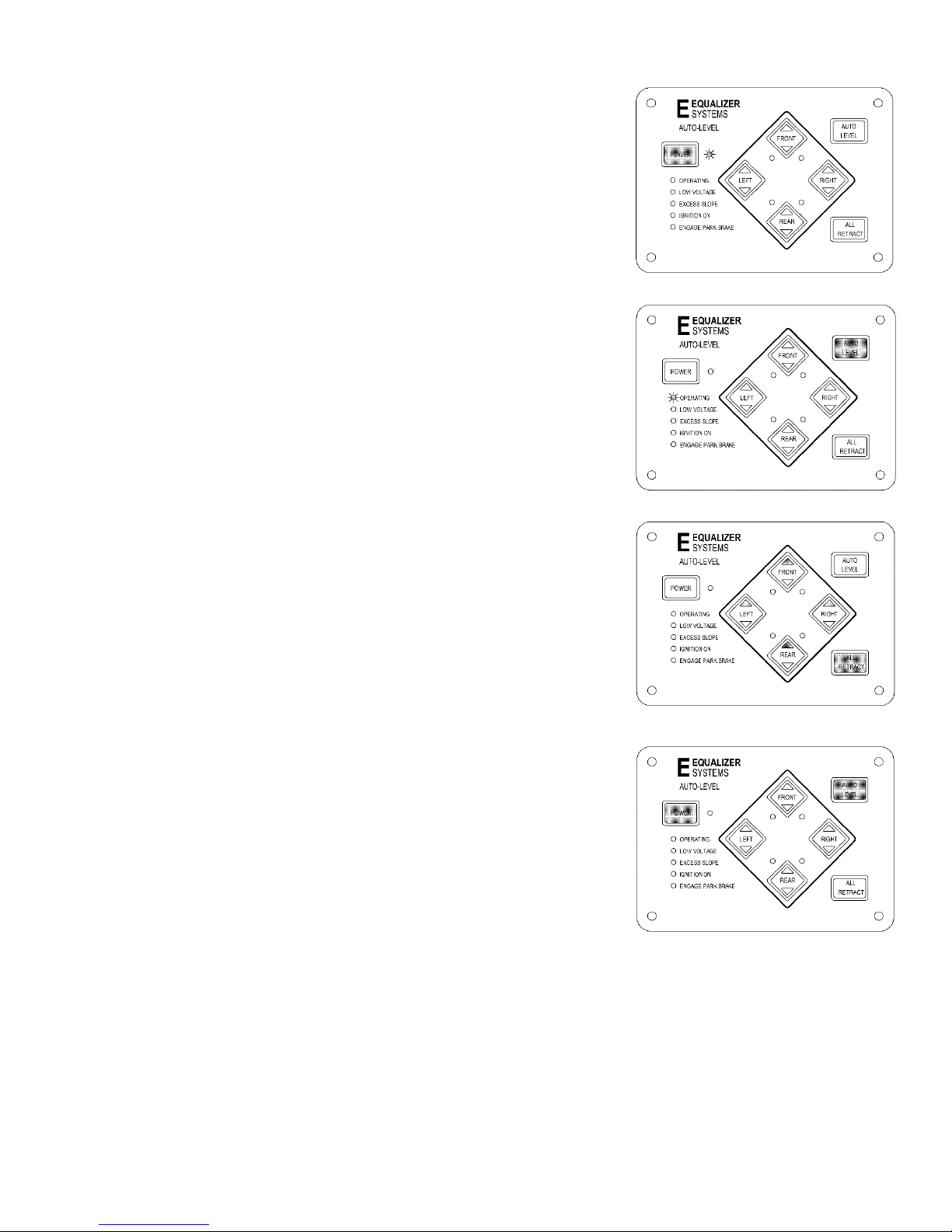
AUTO-LEVEL Operation- Keypad # 3103
Starting Date- Approximately January 2012
• Power On: Press and release the POWER button to engage power. All LED’s on the
panel will come on then most will go out. The LED next to the POWER button should be lit
RED when power is on. The ignition key will need to be in the off position and the park
brake will need to be set to extend the jacks. If you attempt Auto-Level or manual extend
you will hear a “deny” tone if the key or park brake is in the improper position.
• AUTO-LEVEL: Press the AUTO-LEVEL button and release. The system will send
out a continuous series of beeps, the ‘OPERATING’ LED will flash RED to let you
know AUTO-LEVEL is operating and will automatically level the coach. When
completed, the keypad will signal a successful level with a dual-level tone. Press
and release the POWER button. Note: The keypad may be left on once level has
been achieved. The keypad will enter “sleep mode” after five minutes of inactivity.
Note: The jacks down LED lights must be off for Auto-Level to function.
If needed, press the ALL RETRACT button to clear and then Auto-Level
should function.
• Retracting the Jacks: To retract all jacks simultaneously, press and release
the All RETRACT button. All jacks will automatically retract and return to stowed
position. The pump will run in retract mode until all of the jacks are fully stowed
(plus an additional 5 seconds) up to a maximum of 60 or 90 seconds). This is the
proper method for retracting the jacks prior to travel. You may stop the ALL RETRACT
by pressing any button on the keypad. Jacks may be retracted in pairs by using the UP▲
button for each end or side for leveling purposes however the ALL RETRACT must be
used to fully stow the jacks prior to travel. The jacks down LED’s will turn off, indicating the
jacks are in the “stowed” position.
• Power OFF: Press and Release the Power Keypad Button
SETTING THE NULL, “LEVEL POSITION”
• Setting the Null: The Null or “level position” has been preset from the factory.
However, if the coach is not level following an attempt to AUTO-LEVEL, the Null is easy
to reprogram. To set the Null, push and release the POWER keypad button to engage
power. The LED next to the POWER button should be lit RED when power is on. Level
the coach by deploying jacks manually (using the DOWN ▼ keypad buttons, extend
jacks until the coach is level), or by simply parking the coach on a level site. You do not
need to have jacks deployed to set the Null. Use a bubble level on a flat surface in the
center of the coach as a reference. Once the coach is level, turn the POWER off at the
panel. Depress and hold the AUTO-LEVEL keypad button. Continue to hold the AUTOLEVEL button and press then release the POWER button, and listen for a series of beeps.
After the panel has beeped 5 to 6 times, release the AUTO-LEVEL button (the keypad
will continue to beep as long as the AUTO-LEVEL button is held). The new Null has been
set and the system will maintain this setting. Press and release the ALL RETRACT button
to retract the jacks to the stowed position.
*Visually confirm all jacks are retracted prior to travel.
Note: There are specific instances when manual extension of one (or more) jack is inhibited (deny tone when DOWN ▼ is depressed).
This situation is caused by the ‘anti-twist’ protocol in the software contained in the controller. Simply stated, the ‘anti-twist’ protocol
denies jack extension if the system senses that a specific corner of the coach is approximately 3 degrees higher than the rest. You will
be able to extend other jacks to overcome the slope. If the system incorrectly senses excessive slope, this can be overcome by re-
setting the Null. This will allow manual extension of all jacks. Remember to re-set the Null after manually leveling the coach.
3.

Manual Operation- Keypad # 3103
Starting Date- Approximately January 2012
• Power On: Press and release the POWER keypad button to engage power. All LED’s
will come on then most will go out. The LED next to the POWER button should be lit
RED when power is on. The ignition key will need to be in the off position and the park
brake will need to be set to extend the jacks. If you attempt to extend jacks by pressing
the DOWN▼ keypad buttons or all jacks with the AUTO-LEVEL button, you will hear a
“deny” tone from the keypad if the ignition key and or park brake is in the improper
position.
• Planting the Jacks: The jacks will be extended in pairs Fronts or Rears or Left
or Right Using the DOWN▼ (extend) keypad buttons, extend the jacks until they
contact the ground (this is referred to as “planting” the jacks). As you extend each pair
of jacks the corresponding LED jack status lights will come on to indicate jack(s) are out
of the “stowed” position. Jacks will be operated in pairs. Extend and plant the front jacks
first. Then extend and plant the rear jacks. Only after planting the fronts and then the
rears, should side to side corrections (leveling) be attempted. This process will stabilize
all four corners and minimize twist prior to the leveling process.
Do not manually over extend jacks. This may cause unwanted stress on the
coach or the jacks.
• Leveling the Coach: Use a bubble level on a flat surface in the center of the
coach as a reference. Level the vehicle by using DOWN▼ (extend) or UP▲ (retract)
keypad buttons until the vehicle is level. Front to rear then side to side. Jacks will
be operated in pairs. Do not attempt to lift the vehicle tires off of the ground. Only lift
(extend) enough to level and stabilize the unit. Once level, press and release the
POWER button to turn off the keypad. Note: The keypad may be left on once level
has been achieved. The keypad will enter “sleep mode” after five minutes of inactivity.
• Retracting the Jacks: To retract all jacks simultaneously, press and release
the ALL RETRACT button. All jacks will automatically retract and return to stowed
position. The pump will run in retract mode until all of the jacks are fully stowed
(plus an additional 5 seconds- up to a maximum of 60 or 90 seconds). This is the proper
method for retracting the jacks prior to travel. You may stop the ALL RETRACT by
pressing any button on the keypad. Jacks may be retracted in pairs by using the UP▲
button for each end or side for leveling purposes. However, the ALL RETRACT must be
used to fully stow the jacks prior to travel. The jacks down status LED lights will turn off,
indicating the jacks are in the stowed position.
• Power OFF: Press and release the POWER keypad button.
Visually Confirm all Jacks are Retracted Prior to Travel
There are ten (10) LED indicators on the AUTO-LEVEL keypad. The functions of these LED’s are detailed below.
4.

Keypad Indicator LED’s
During typical operation, the
only LED that should light is the
‘POWER’
‘JACK’
LED (4 each) ............................. ON Red when jack(s) are deployed
‘OPERATING’
‘LOW VOLTAGE’
‘ENGAGE
‘IGNITION ON’
‘EXCESS SLOPE’
Note: If the LOW VOLTAGE, ENGAGE PARK BRAKE< IGNITION ON or EXCESS SLOPE
LED’s illuminate, an “error” condition is present and must be corrected prior to operating
the jacks.
5.
LED’s
on
the bottom left hand corner of the keypad should NOT be illuminated. The
‘OPERATING’
LED .......................................... ON Red when power is ON
LED, which should flash during operation.
OFF when power is OFF
FLASH every 5 sec. In Sleep Mode
OFF when jack(s) are stowed
LED ................................. ON Red w/ Auto Level or All Retract
OFF when keypad is idle or ‘sleeping’
LED .......................... ON Red when voltage is below 10.5 volts dc
OFF when voltage is above 10.5 volts dc
PARK
BRAKE’
LED........... ON Red when park brake is not set
OFF when park brake is set.
LED ............................... ON Red when ignition is in the ON position
OFF when ignition is OFF
LED .......................... ON Red
system cannot overcome slope
OFF when slope is not excessive
following
an Auto Level attempt, if

Helpful Hints
Your coach is equipped with an air suspension.
The air suspension is deflated when the auto-level button is pressed and re-inflated when the all retract button is pressed.
The re-inflation requires that there is air pressure available to inflate the air suspension when the all retract button is
pressed. So it is recommended that the engine be started and air pressure allowed to build prior to pressing all retract to
assure that air is available to inflate the air suspension.
Your leveling system is equipped with an override option.
See the section on override. This is to allow you to get the jacks retracted in the event of electrical failure. It is
recommended that you review and understand this procedure prior to its need rather than to learn the procedure in
difficult environments.
Automatic functions.
You may stop automatic functions (auto level or all retract) at any time by pressing any button on the keypad. If auto
level is in process and the ignition key is turned to the engine run position or the park brake is released auto level will stop
and the warning beeper will come on and the jacks down status lights will flash.
Movement during auto level.
Excessive movement in or of the coach during the auto level process may result in the system not leveling properly.
Examples of this are strong winds that rock the coach during the auto level process or getting out of the coach causing a
rocking during the leveling process.
Proper Voltage.
The auto level system is a micro processer controlled system that requires adequate voltage and a permanent chassis
ground. Low voltage and or poor connections can prevent the operation or stop the operation in process.
Unit storage.
If the unit is stored for more than 24 hrs. with the jacks retracted it is possible that the jacks down status lights will come
on when the key is turned to the engine run position. Simply press the all retract button to clear the lights and the warning
buzzer.
Maintenance Items
Maintain the reservoir fluid level to a minimum ¾ full when the jacks are fully retracted. Use automatic transmission fluid
that meets a Dexron specification, the use of the “multipurpose” automatic transmission fluid is fine.
Change the fluid in the reservoir if it shows signs of contamination, debris or water.
The cylinder rods may be cleaned and protected by using WD-40 or equivalent.
Proper maintenance of the vehicles batteries and electrical system is important for proper system operation. Proper
voltage and grounding is critical. Follow the battery and coach manufactures guidelines for proper care and maintenance.
Additional Maintenance items and Troubleshooting items may be found on the web site
www.equalizersystems.com
6.

Override procedure
The leveling system is equipped with an override option to allow for the retraction of the jacks if the electrical system has
faulted. Generally if the fault is week or dead batteries it is best to charge the batteries and operate the system normally.
The procedure requires a 1/8 inch Allen wrench and an electric drill (recommended 2000 rpm) with a 7/16 hex driver.
1. Locate and access the pump/manifold assembly. Generally it will be located behind a plastic shield in one of the
forward storage compartments.
2. On the side of the manifold there are 4 individual cartridge valves (one for each jack leg). There is an Allen (1/8
inch) screw recessed in the center of the end of the valve stem. Using a 1/8 inch Allen wrench turn the screw(s) in
Clockwise approximately 2 turns until they stop. All 4 may be selected or just the ones that are for the jack(s) that
are needing to have the override performed on. (See Drawing)
Note: some units may have a single valve on the opposite side (retract) of the manifold, if so it must have the
screw turned in as above.
3. Locate the plastic plug at the end of the motor use a small screw driver to pry out the plug. This will expose the
motor override hex. Using a drill with a 7/16 hex drive bit run the drill in the Counter-Clockwise direction to
retract the jack(s) until they are fully retracted. Re-install the plug when completed. (See Drawing)
Hint: If the pump motor will run from the Keypad using the drill may not be needed. Simply press the all
retract after step 2.
4. When the jack(s) are fully retracted return all of the override screws (item 2 above) to their original out counterclockwise position.
Important failure to return the valves to the out (counter-clockwise) position may result in the jacks
“Drifting” from the stowed position.
7.

Equalizer Systems Limited Warranty Policy
March 2017
1. Only warranty claims with prior written or verbal authorization from Equalizer Systems will be recognized, all other claims will
be denied.
2. Equalizer Systems warrants slide out and leveling system components for a period of two years from the date of original sale of
the vehicle. This warranty covers defects in material and workmanship only. Equalizer Systems is not liable for any damage due to
abuse, neglect, misuse, negligence, misapplication, error of operation, accidental or purposeful damage or damage due to an “act of
God” such as, wind or rain damage, flood, lightning or other natural occurrence of the like. Equalizer Systems limited warran ty is
applicable to the Equalizer Systems components only and does not apply to the vehicle, apparatus or property to which it is
attached. Warranty parts will be shipped at no charge if the repair is authorized by an Equalizer Systems representative. Purchased
components used in authorized warranty repairs will be reimbursed at the original purchase price.
3. Labor and freight expenses due to warrantable parts defects or workmanship will be reimbursed for a period of one year from the
date of original sale of the vehicle. Freight expenses will either be prepaid by Equalizer Systems or reimbursed at the UPS Ground
rate only. Any additional shipping charges or requirements are the obligation of the vehicle owner or service center performing the
warranty repair. The owner or service center’s obligation may include overseas shipping charges, border fees, brokerage fees and
any other additional fee of the like.
4. Warranty labor will be reimbursed only for claims that have prior written or verbal authorization from an Equalizer Systems
representative. Warranty labor compensation is required to correspond with the “Warranty Parts Replacement Time Guideline”
published by Equalizer Systems. Any warranty repair not listed on this guideline will require prior authorization from an Equalizer
Systems representative. A reasonable time allowance will be determined by the Equalizer Systems representative. Any warranty
repair that is not listed on this guideline that is performed without prior authorization will be denied without exception. Time
associated with learning about the repair or excessive diagnostic and installation time will not be reimbursed. Warranty labor will be
reimbursed at the authorized service center’s published shop rate if the rate is reasonable for that region. Overtime labor will not be
reimbursed without exception.
5. Labor, parts and freight credit (if applicable) will be sent after the parts are tested and the warranty claim is validated. Returned
parts that are found to be in normal operating condition are not warrantable and will be charged to the owner or service center.
Equalizer Systems reserves the right to charge back the service center for labor claim payments previously submitted if the
installation of the warranted part is found to be inadequate at a later date.
6. Claims will be denied if the date submitted is greater than 30 days from the repair date.
7. Prior authorization is required before parts may be sent back to Equalizer Systems. A Return Authorization Number is required
for items to be accepted.
8. Complete systems are not warranted unless authorized by an Equalizer Systems representative. There are absolutely no
exceptions to this clause.
9. Warranty coverage for parts or systems sold by non-authorized resellers (such as live or internet auctions) will be at the discretion
of Equalizer Systems.
10. Equalizer Systems is not liable for loss of time, manufacturing costs, labor, material, loss of profits, direct or indirect damages
incurred by the vehicle manufacturer.
11. Excessive warranty labor resulting from inadequate access to the Equalizer Systems product will not be reimbursed.
12. Equalizer Systems will not pay a markup on warranty parts unless required by law.
13. Travel expenses, hotel, telephone, fuel or any other expenses of the like are not covered under warranty.
Replacement Parts:
1. Replacement parts are warranted under the same guidelines listed above for the remainder of the original warranty or 90 days,
whichever is longer. Proof of warranty repair date and original vehicle purchase date are required.
No additional warranties, expressed or implied, are authorized by Equalizer Systems
This warranty voids all previous issues.
Questions concerning this warranty should be directed to:
To activate your warranty, please visit our website at http://equalizersystems.com/service/activate-warranty
OM001-ER1
Equalizer Systems
55169 CR 3 North
Elkhart, IN 46515
1-(800) 846-9659
1-(574) 266-6083 fax
 Loading...