

Page 1
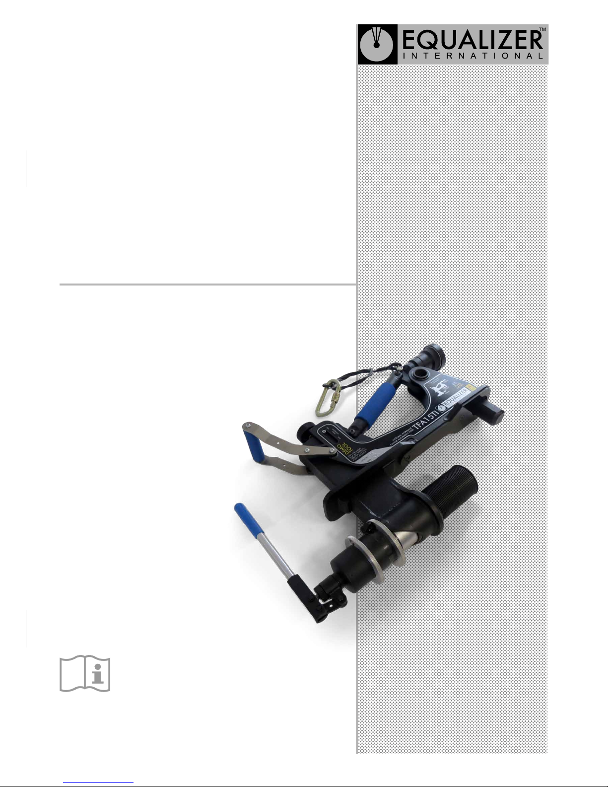
OPERATOR INSTRUCTION MANUAL
TFA12TI
TFA15TI
TFA12TIRD37H
TFA15TIRD37H
EQUALIZER INTERNATIONAL LTD
www.equalizerinternational.com
INTEGRAL
HYDRAULIC
FLANGE
ALIGNMENT
TOOLS
Page 2

OPERATOR INSTRUCTION MANUAL
IM_TFA_TI_Rev01_A4
TFA INTEGRAL HYDRAULIC TOOLS
FLANGE ALIGNMENT TOOLS
2
CONTENTS
1. INTRODUCTION
2. TOOL SAFETY
2.1 GENERAL SAFETY
2.2 PERSONNEL COMPETENCY
2.3 DISCLAIMER
2.4 DEFINITION OF TERMS
2.5 HAZARDS
3. TOOL OPERATION
3.1 GENERAL GUIDANCE
3.2 HANDLING
3.3 TOOL INSTALLATION
3.4 ADJUSTMENT LEG
3.5 WING EXTENSION
3.6 CYLINDER ADJUSTMENT SLEEVE
3.7 TOOL CHECKS
3.8 ALIGNMENT
3.9 SECURING THE FLANGE JOINT
4. TOOL MAINTENANCE
4.1 INSPECTION
4.2 CLEANING
4.3 SERVICING
4.4 LUBRICATION PROCEDURE
4.5 STORAGE & TRANSPORTATION
4.6 OPERATING CONDITIONS
4.7 SUB-SEA USAGE
5.
5.1 TOOL CAPABILITIES
5.2 TOOL FUNCTION
5.3 KIT CONTENTS
5.4 DIMENSIONS
6. TROUBLESHOOTING
7. REGULATORY INFORMATION
7.1 REGISTERED HEAD OFFICE
7.2 APPLICABLE PATENT NUMBERS
8. PARTS LISTS & SERVICE KITS
15/06/17
Page 3
OPERATOR INSTRUCTION MANUAL
IM_TFA_TI_Rev01_A4
TFA INTEGRAL HYDRAULIC TOOLS
FLANGE ALIGNMENT TOOLS
3
2.
TOOL SAFETY
2.1
GENERAL SAFETY
These instructions cover the safe operation and
maintenance of THE EQUALIZER RANGE OF TFA
INTEGRAL HYDRAULIC FLANGE ALIGNMENT tools.
The use of any tools should be as part of a broader taskbased risk assessment, which should be carried out by the
operation supervisor or other competent person.
Failure to comply with the safety information contained
within this manual could result in personal injury or
equipment damage. Read all instructions, warnings and
cautions carefully, and follow all safety precautions.
The safety of the operator, any assisting personnel and
the general public is of paramount importance. Always
work in accordance with applicable national, local, site &
company-wide safety procedures.
2.2
PERSONNEL COMPETENCY
Only personnel deemed competent in the use of mechanical
and hydraulic equipment should use these tools.
2.3
DISCLAIMER
Equalizer cannot be held responsible for injury or damage
resulting from unsafe product use, lack of maintenance
or incorrect product and/or system operation. If in doubt
as to the safety precautions and applications, contact
Equalizer using the contact details at the back of this
manual.
1.
INTRODUCTION
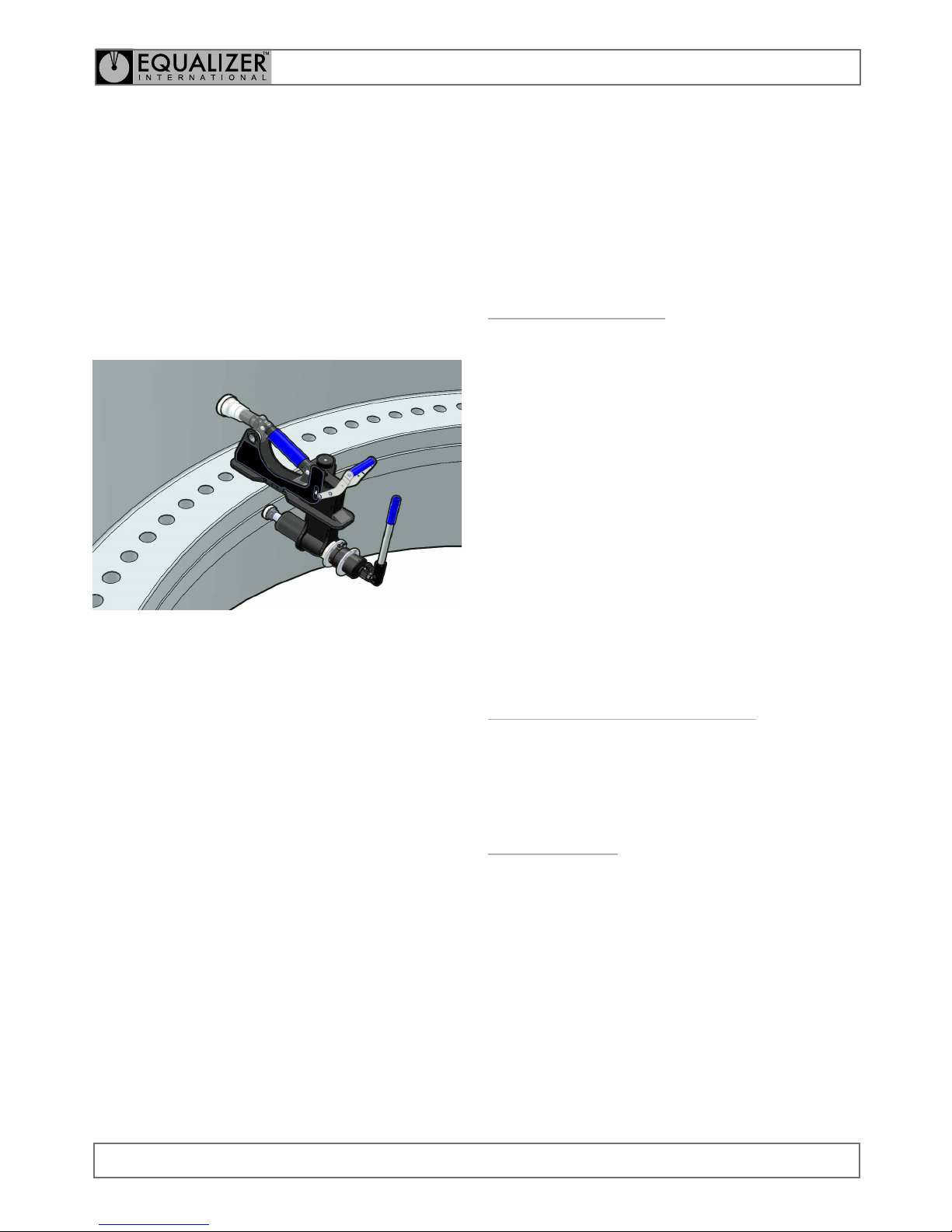
The Equalizer™ range of TFA integral hydraulic ange
alignment tools have been developed to assist in the
aligning of large anges on the inside of large pipes, for
example those which make up the tower sections of a
wind-turbine.
The tools have been designed to cope with the larger
loads and dimensions associated with these ange joints
while remaining relatively lightweight and user-friendly.
It is essential that the users familiarise themselves with
the contents of this manual prior to using the tool.
This manual contains information for the following tools:
• TFA12TI
Integral Hydraulic Flange Alignment Tool
• TFA15TI
Integral Hydraulic Flange Alignment Tool
• TFA12TIRD37H
Integral Hydraulic Flange Alignment Tool
• TFA15TIRD37H
Integral Hydraulic Flange Alignment Tool
Page 4
OPERATOR INSTRUCTION MANUAL
IM_TFA_TI_Rev01_A4
TFA INTEGRAL HYDRAULIC TOOLS
FLANGE ALIGNMENT TOOLS
4
internal damage to hose wire strands. Protect
hoses from crush risks, such as heavy objects
or vehicles; crush damage can cause hose
failure.
WARNING: Applying pressure to a damaged
hose may cause it to rupture.
WARNING: Immediately replace worn or
damaged parts. Use only genuine Equalizer
parts from approved distributors or service
centres. Equalizer parts have been engineered
and manufactured to be t-for-purpose.
DANGER: To minimise risk of personal injury
keep hands and feet away from the tool and
workpiece during operation.
WARNING: Always wear suitable clothing and
Personal Protective Equipment (PPE). Do not
handle pressurised hoses; escaping oil under
pressure can penetrate the skin, causing serious
injury. Seek medical attention immediately if oil
penetration is suspected.
WARNING: Only pressurize complete and fully
connected hydraulic systems. Do not pressurize
systems that containt unconnected couplers.
CAUTION: Do not lift hydraulic equipment by
the hoses or couplers. Use only the designated
carrying handles.
CAUTION: Lubricate tools as directed in this
manual prior to operation. Use only approved
lubricants of high quality, following the lubricant
manufacturers instructions.
2.4
DEFINITION OF TERMS
A CAUTION is used to indicate correct operating or
maintenance procedures and practices to prevent damage
to, or destruction of equipment or other property.
A WARNING indicates a potential danger that requires
correct procedures or practices to avoid personal injury.
A DANGER is only used when your action or lack of action
may cause serious injury or even death.
DO: an illustration showing how the tool should
be used.
DON’T: an illustration showing an incorrect way
to use a tool.
2.5
HAZARDS
WARNING: ensure all hydraulic components are
rated to a safe working pressure of 700 bar
(10 000 psi).
WARNING: Do not overload equipment. The
risk of hydraulic overloading can be minimised
by using the Equalizer Hand Pump, which has a
factory-set safety valve preventing the safe
working pressure being exceeded.
If alternative hydraulic pumps are used, ensure
that there are adequate systems to limit the
the working pressure to 700 bar (10 000 psi).
CAUTION: ensure components are protected
from external sources of damage, such as
excessive heat, ame, moving machine parts,
sharp edges and corrosive chemicals.
CAUTION: Take care to avoid sharp
bends and kinks in hydraulic hoses.
Bends and kinks can cause severe
back-up pressure and cause hose
failure. Protect hoses from dropped
objects; a sharp impact may cause
Page 5
OPERATOR INSTRUCTION MANUAL
IM_TFA_TI_Rev01_A4
TFA INTEGRAL HYDRAULIC TOOLS
FLANGE ALIGNMENT TOOLS
5
3.2
HANDLING
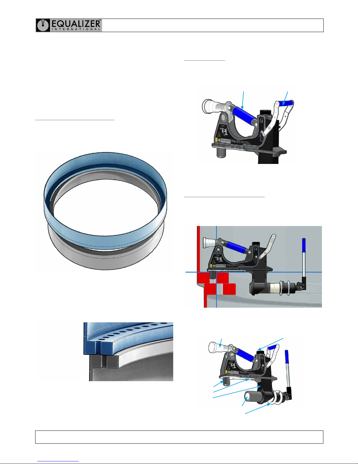
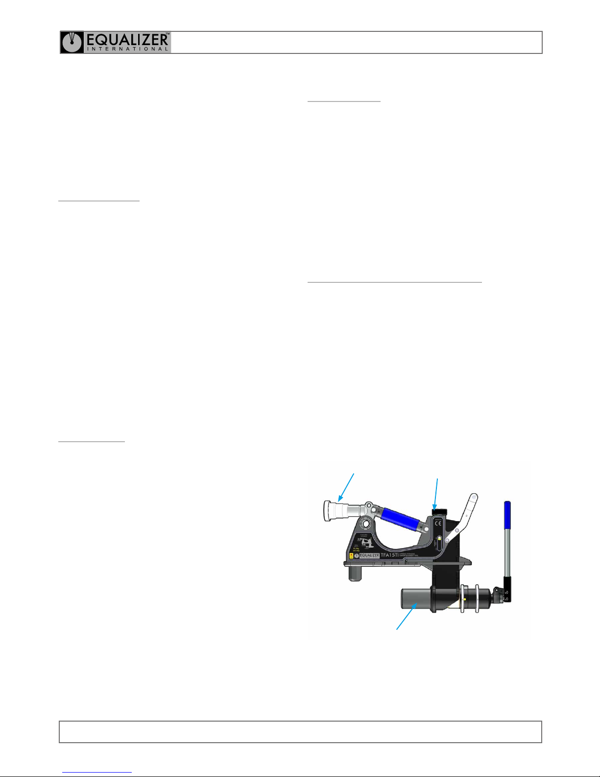
The tool should be lifted and manouvered using its two
handles.
BACK HANDLE
FRONT HANDLE
3.3
TOOL INSTALLATION
Position the tool into the bolt-hole ensuring that the hook
is fully located into the bolt-hole and the base plate of the
tool is sitting at against the upper ange.
HOOK
BASE PLATE
WING
WING
ADJUSTMENT
ADJUSTMENT LEG
CYLINDER ADJUSTMENT
ALIGNMENT PISTON
3.
TOOL OPERATION
3.1
GENERAL GUIDANCE
Prior to alignment, an assessment should be carried out
to determine the most appropriate positioning of the tool
on the ange joint.
The TFA ange alignment tool should always be installed
in such a way that the lower ange is closer to the user
and the upper ange is further away. The tool is designed
to hook into the bolt-hole of the upper ange and push
the lower ange into alignment.
Prior to installation, ensure the Adjustment Leg and
Cylinder Adjustment Sleeve are fully retracted. Ensure
that the Alignment piston is fully retracted.
Page 6
OPERATOR INSTRUCTION MANUAL
IM_TFA_TI_Rev01_A4
TFA INTEGRAL HYDRAULIC TOOLS
FLANGE ALIGNMENT TOOLS
6
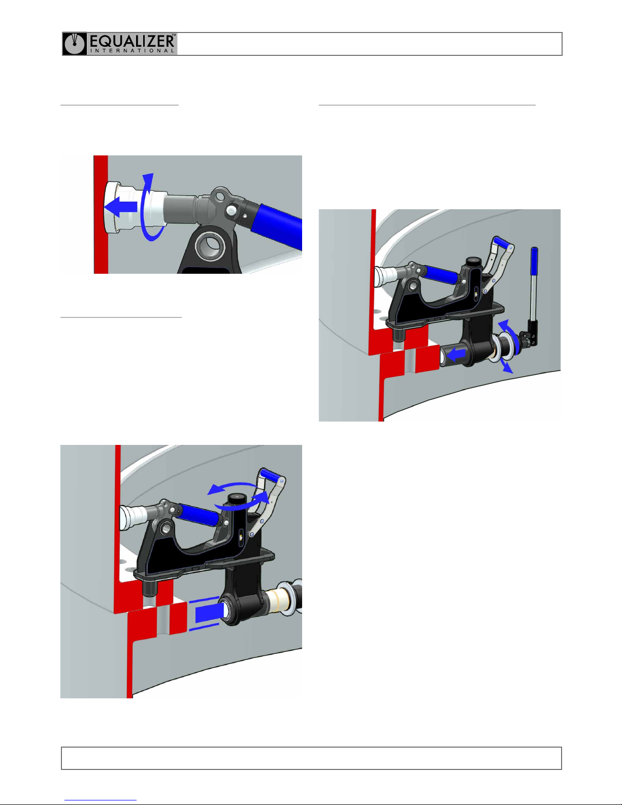
3.6
CYLINDER ADJUSTMENT SLEEVE
The Alignment Piston has a 65 mm stroke. The Cylinder
Adjusment Sleeve extends the reach of the tool to t a
variety of ange sizes, without comprimising its maximum
alignment capacity.
Turn the Cylinder Adjustment Sleeve by the knurled ring
until the Alignment Foot is touching the lower ange.
3.4
ADJUSTMENT LEG
Extend the Adjustment Leg by turning the knurled foot
clockwise until it contacts the pipe wall. Ensure that the
tool is sitting squarely.
3.5
WING EXTENSION
The Alignment Piston is located on an adjustable wing
which can be extended to enable the tool to be used on a
variety of ange sizes.
Use the Wing Extension adjustment knob to lower the
wing until the foot of the Alignment piston is positioned
within the space between the upper and lower faces of
the lower ange.
Page 7

OPERATOR INSTRUCTION MANUAL
IM_TFA_TI_Rev01_A4
TFA INTEGRAL HYDRAULIC TOOLS
FLANGE ALIGNMENT TOOLS
7
3.8
ALIGNMENT
Refer to section 5.2 for tool actuation instructions.
Actuating the tool will extend the Alignment Piston and
align the anges.
3.9
SECURING THE FLANGE JOINT
After the ange joint has been aligned it can be secured
by installing as many bolts as possible into the bolt holes.
It may be necessary to repeat the alignment process
several times while working around the ange joint.
3.7
TOOL CHECKS
Ensure that the tool is sitting square on the
ange, that the wing is parallel to the pipe wall
and that the Adjustment Leg is adjusted prior
to actuating the tool. Actuating the tool when it
is not correctly installed could cause injury or
equipment damage.
Do not allow ngers, hands or other body parts
to come into contact with the ange while
actuating the tool. Only hold the tool by its
designated handles.
Page 8
OPERATOR INSTRUCTION MANUAL
IM_TFA_TI_Rev01_A4
TFA INTEGRAL HYDRAULIC TOOLS
FLANGE ALIGNMENT TOOLS
8
4.3
SERVICING
Replace missing worn or damaged parts. Use only
genuine Equalizer parts from approved distributors or
service centres. Equalizer parts have been engineered and
manufactured to be t-for-purpose.
Grease all moving parts by following the Lubrication
Procedure prior to usage, storage or transportation.
If topping up or replacing hydraulic oil as part of a service,
use only premium quality hydraulic oil of the grade 15 cSt.
4.4
LUBRICATION PROCEDURE
Apply grease following cleaning and servicing, prior to
usage, storage or transportation. Never assemble and
leave a tool without following the greasing procedure as
degradation or damage may occur.
Use only high pressure molybdenum disulphide grease.
Apply grease liberally to the following areas:
• the Adjustment Leg thread
• the Wing Extension thread
• the Cylinder Adjustment thread
ADJUSTMENT
LEG THREAD
CYLINDER
ADJUSTMENT
THREAD
WING
EXTENSION
THREAD
4.
TOOL MAINTENANCE
4.1
INSPECTION
A thorough inspection should be carried out prior to usage,
storage or transportation to ensure the completeness and
condition of the tool.
Inspection should include:
• visual inspection of the outer parts of the tool,
checking for obvious damage, degradation or missing
parts
• visual inspection of the Alignment Piston (requiring
tool actuation). Damage to the Alignment Piston can
be indicative of tool over-load.
Cleaning and servicing should be undertaken as required
prior to the tool being used, stored or transported.
4.2
CLEANING
To lightly clean the tool, wipe gently with a damp cloth.
If more thorough cleaning is required (for example
following immersion in water) carry out the following
cleaning procedure:
• strip the tool down, observing the schematics in
section 8
• clean the components using detergent, following the
manufacturer’s guidelines
• rinse the components to remove traces of detergent
• dry the components thoroughly
Inspect, service and lubricate the tool immediately after
the cleaning process.
Page 9
OPERATOR INSTRUCTION MANUAL
IM_TFA_TI_Rev01_A4
TFA INTEGRAL HYDRAULIC TOOLS
FLANGE ALIGNMENT TOOLS
9
4.5
STORAGE & TRANSPORTATION
Equalizer tools should be stored in a cool dry place. Tools
should always be cleaned, serviced and lubricated prior to
storage. Ensure that tools are stored in their designated
packing cases.
4.6
OPERATING CONDITIONS
HYDRAULIC TOOLS:
Minimum Flange Contact Temperature: -30 °C (-22 °F)
Maximum Flange Contact Temperature: 70 °C (158 °F)
4.7
SUB-SEA USAGE
Using TFA integral hydraulic tools Sub-Sea
The TFA integral hydraulic tools are actuated by means of
a single-acting spring-return hydraulic cylinder and can be
used sub-sea providing the following actions are taken:
• The pump release valve is fully opened and remains
open until the tool has descended to the working
depth. This will allow the pressure to equalise.
• The tool is actuated via the hand pump by a diver.
• Upon completion of works the release valve is left in
the fully-open position until the tool has ascended to
the surface.
• The tool and pump are stripped-down, cleaned and
lubricated immediately to minimise corrosion.
Page 10
OPERATOR INSTRUCTION MANUAL
IM_TFA_TI_Rev01_A4
TFA INTEGRAL HYDRAULIC TOOLS
FLANGE ALIGNMENT TOOLS
10
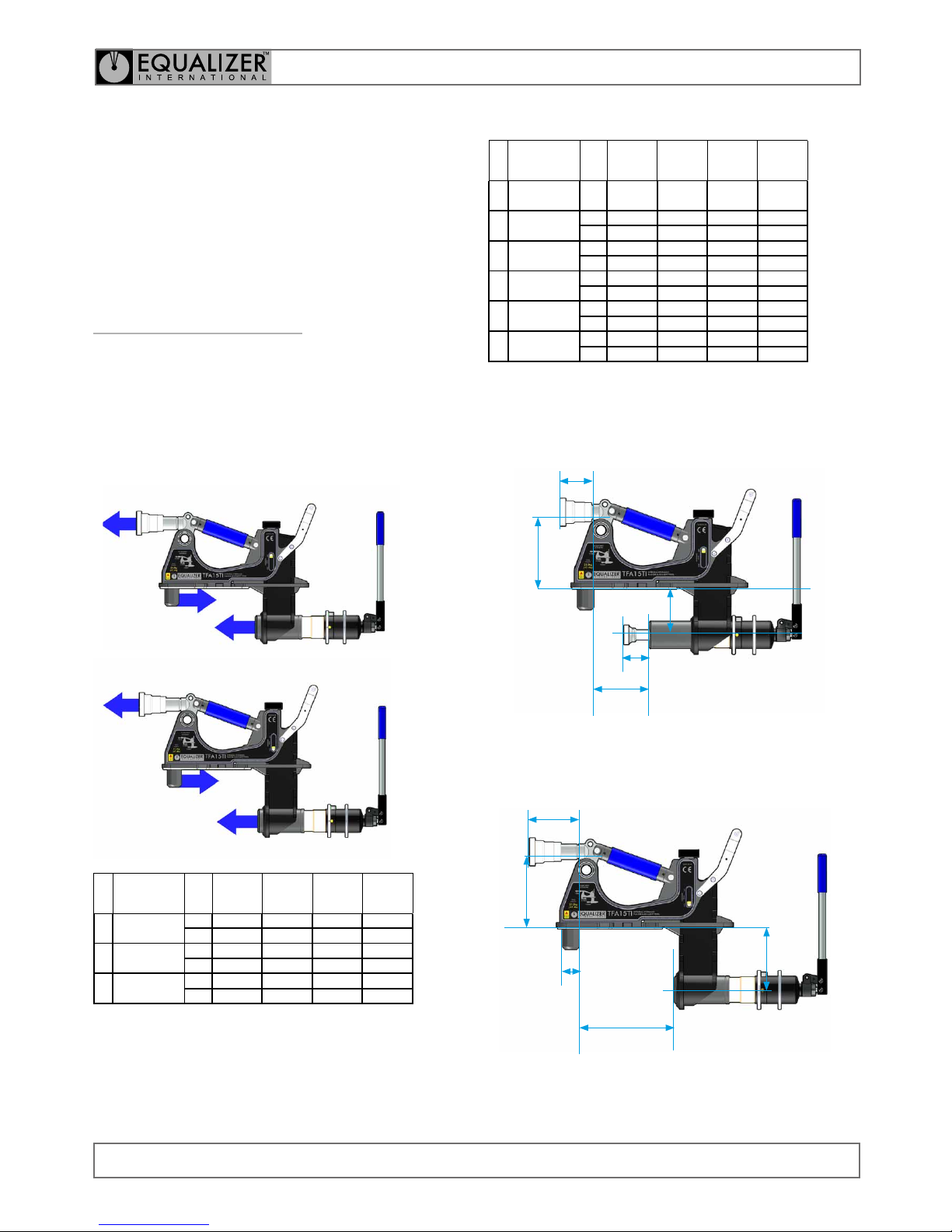
RANGE OF APPLICATION
DIMENSION TFA12TI TFA15TI
TFA12TI
RH37H
TFA15TI
RH37H
B
Bolt Hole
Diameter
45 mm 45 mm 37 mm 37 mm
M Misalignment
MIN 0 mm 0 mm 0 mm 0 mm
MAX 65 mm 65 mm 65 mm 65 mm
R Rise
MIN 150 mm 150 mm 150 mm 150 mm
MAX 250 mm 250 mm 250 mm 250 mm
D Pipe Leg Drop
MIN 83 mm 83 mm 53 mm 53 mm
MAX 123 mm 123 mm 93 mm 93 mm
W Wing Reach
MIN 160 mm 120 mm 160 mm 120 mm
MAX 203 mm 160 mm 203 mm 160 mm
H
Reaction
Spacing
MIN 200 mm 200 mm 275 mm 275 mm
MAX 200 mm 200 mm 275 mm 275 mm
MINIMUM EXTENSION
MAXIMUM EXTENSION
W
min
H
D
min
M
max
R
min
W
max
H
D
max
R
max
B
min
5.
The TFA integral hydraulic ange alignment tools use an
integral hydraulic cylinder to advance the alignment foot
and align the anges.
5.1
TOOL CAPABILITIES
ALIGNMENT FORCE
The following table shows the alignment force (F)
through the alignment foot when the maximum integral
pump pressure is applied. Reaction forces (R1 & R2) vary
depending on the extension of the wing.
R
1
F
R
2
R
1
F
R
2
MIN.
WING
EXTENSION
MAX.
WING
EXTENSION
FORCE TFA12TI TFA15TI
TFA12TI
RH37H
TFA15TI
RH37H
F
ALIGNMENT
FORCE
MIN 12 T 15 T 12 T 15 T
MAX 12 T 15 T 12 T 15 T
R
1
REACTION
FORCE 1
MIN 10 T 9 T 7 T 6.5 T
MAX 12 T 12 T 8.7 T 8.7 T
R
2
REACTION
FORCE 2
MIN 22 T 24 T 19 T 21.5 T
MAX 24 T 27 T 20.7 T 23.7 T
Page 11
OPERATOR INSTRUCTION MANUAL
IM_TFA_TI_Rev01_A4
TFA INTEGRAL HYDRAULIC TOOLS
FLANGE ALIGNMENT TOOLS
11
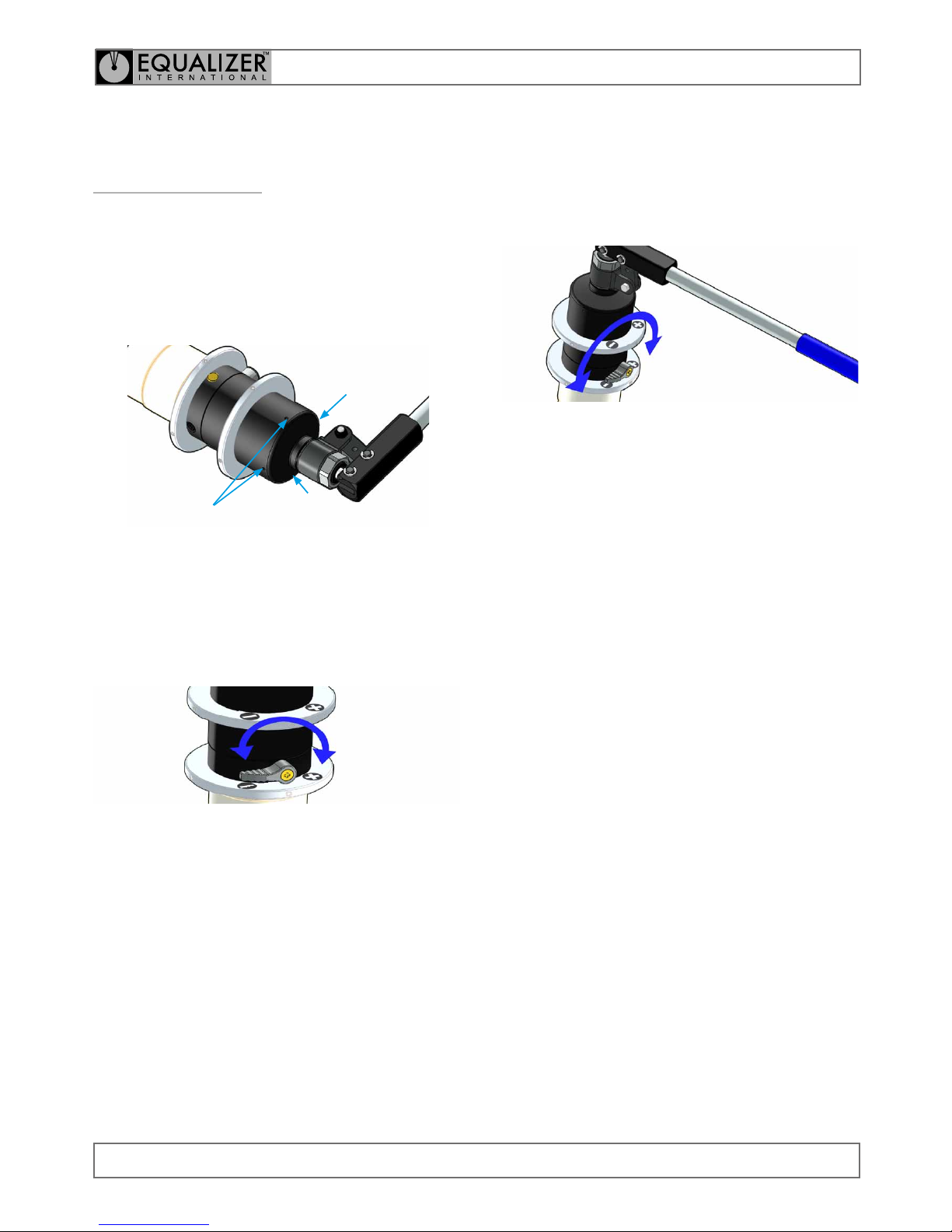
ACTUATING THE TOOL
Follow the Tool Operation instructions (see Section 3),
using the following instructions to actuate the tool.
When advance (+) is selected, pumping the handle will
advance the Alignment Piston.
RETRACTING THE TOOL
Selecting retract (-) will depressurise the cylinder and
cause it to retract under the force of its internal spring.
The handle does not need to be pumped to retract the
tool.
5.2
TOOL FUNCTION
HYDRAULIC TOOL OPERATION
Prior to operation, ensure the air-vent in the integral hand
pump is not obstructed. Any obstruction in the air-vent
can cause a vacuum in the system which can limit the
cylinder’s travel.
AIR-VENTS
The TFA integral hydraulic tools use a hydraulic cylinder to
advance the Alignment Piston and align the anges. The
hydraulic pressure is applied using the integrated hand
pump, enabling accurate control of the force applied.
The integral hand pump has a control lever which allows
the user to select advance (+) or retract (-).
Page 12
OPERATOR INSTRUCTION MANUAL
IM_TFA_TI_Rev01_A4
TFA INTEGRAL HYDRAULIC TOOLS
FLANGE ALIGNMENT TOOLS
12
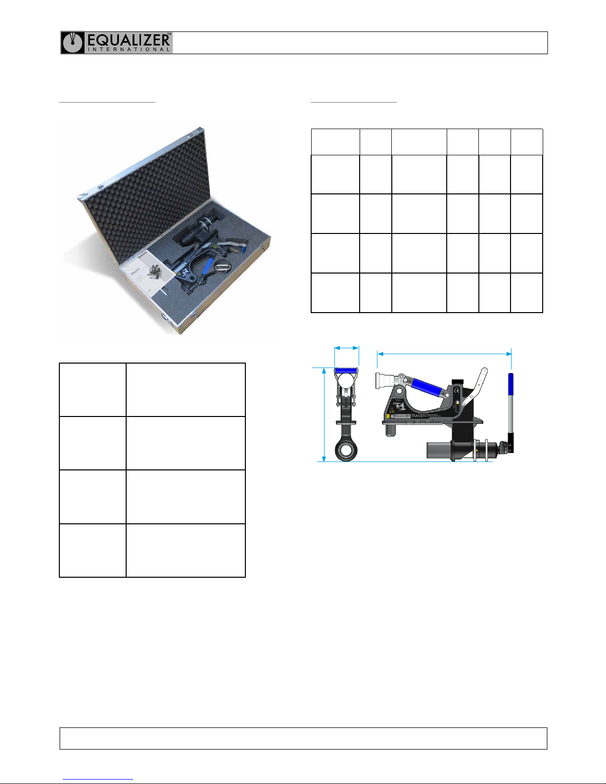
5.4
DIMENSIONS
TOOL
WEIGHT
BOX
DIMENSIONS
X Y Z
TFA12TI
20.5 kg
(45.2 lb)
585 mm (23.0”)
900 mm (35.4”)
160 mm (11.8”)
104 mm
(4.10”)
470 mm
(18.5”)
635 mm
(25.0”)
TFA15TI
20 kg
(44.1 lb)
585 mm (23.0”)
900 mm (35.4”)
160 mm (11.8”)
104 mm
(4.10”)
430 mm
(16.9”)
635 mm
(25.0”)
TFA12TI
RH37H
22.3 kg
(49.2 lb)
585 mm (23.0”)
900 mm (35.4”)
160 mm (11.8”)
104 mm
(4.10”)
521 mm
(20.5”)
636 mm
(25.0”)
TFA15TI
RH37H
21.7 kg
(47.8 lb)
585 mm (23.0”)
900 mm (35.4”)
160 mm (11.8”)
104 mm
(4.10”)
482 mm
(19.0”)
636 mm
(25.0”)
Y
X
Z
5.3
KIT CONTENTS
TFA12TI
STANDARD KIT
1 x TFA12TI Tool
1 x Instruction Manual
1 x Hard Case
Product Code: TFA12TISTD
TFA15TI
STANDARD KIT
1 x TFA15TI Tool
1 x Instruction Manual
1 x Hard Case
Product Code: TFA15TISTD
TFA12TIRD37H
STANDARD KIT
1 x TFA12TIRD37H Tool
1 x Instruction Manual
1 x Hard Case
Product Code: TFA12TIRD37HSTD
TFA12TIRD37H
STANDARD KIT
1 x TFA15TIRD37H Tool
1 x Instruction Manual
1 x Hard Case
Product Code: TFA15TIRD37HSTD
Page 13

OPERATOR INSTRUCTION MANUAL
IM_TFA_TI_Rev01_A4
TFA INTEGRAL HYDRAULIC TOOLS
FLANGE ALIGNMENT TOOLS
13
THE ALIGNMENT PISTON MOVES AS
INTENDED, BUT DOESN’T SEEM TO BE
ACHIEVING FULL PRESSURE WHEN UNDER
LOAD
POSSIBLE CAUSE:
Intermediate valve not seating / relief valve leaking.
RECOMMENDED ACTION:
Refer to an approved Equalizer distributor for further
instruction.
HYDRAULIC PRESSURE SLOWLY DIMINISHES
AND THE PUMP HANDLE RISES
POSSIBLE CAUSE:
The outlet check valve is leaking.
RECOMMENDED ACTION:
Refer to an approved Equalizer distributor for further
instruction.
HYDRAULIC PRESSURE SLOWLY DIMINISHES
AND THE PUMP HANDLE DOES NOT RISE
POSSIBLE CAUSE:
The release valve is leaking.
RECOMMENDED ACTION:
Refer to an approved Equalizer distributor for further
instructions.
POSSIBLE CAUSE:
The piston seal is leaking.
RECOMMENDED ACTION:
Inspect the tool for oil leaks, possibly indicative
of a perished seal or loose blanking plug. Refer
to an approved Equalizer distributor for further
instructions.
TOOL ACTUATION FEELS SOFT AND
UNRESPONSIVE
POSSIBLE CAUSE:
There is air in the hydraulic system.
RECOMMENDED ACTION:
Refer to an approved Equalizer distributor for further
instruction.
6.
TROUBLESHOOTING
THE ALIGNMENT PISTON ADVANCES
SOME OF THE WAY AND THEN STOPS
PROGRESSING
POSSIBLE CAUSE:
The air-vent is obstructed by dirt or debris.
The tool has reached its maximum load.
RECOMMENDED ACTION:
Carefully unblock the air-vent using a small blunt
object.
THE ALIGNMENT PISTON DOESN’T MOVE
POSSIBLE CAUSE:
There is an air-lock within the hydraulic system.
RECOMMENDED ACTION:
Select Retract (-) and prime pump to circulate oil
around the system.
POSSIBLE CAUSE:
Insufcient oil in the hydraulic system.
RECOMMENDED ACTION:
Refer to an approved Equalizer distributor for further
instruction.
POSSIBLE CAUSE:
Retract (-) is selected.
RECOMMENDED ACTION:
Select Advance (+) and pump the handle.
POSSIBLE CAUSE:
Air has accumulated around pump inlet when used
upside down.
RECOMMENDED ACTION:
Inspect the tool for oil leaks on the reservoir,
possibly indicative of a perished bladder. Refer to an
approved Equalizer distributor for repair.
Page 14

OPERATOR INSTRUCTION MANUAL
IM_TFA_TI_Rev01_A4
TFA INTEGRAL HYDRAULIC TOOLS
FLANGE ALIGNMENT TOOLS
14
8.
PARTS LISTS
& SERVICE KITS
7.
REGULATORY
INFORMATION
7.1
REGISTERED HEAD OFFICE
EQUALIZER INTERNATIONAL LTD.
Equalizer House
Claymore Drive
Aberdeen
Scotland
AB23 8GD
7.2
APPLICABLE PATENT NUMBERS
The following list of Patents and Design Registrations are
applicable to EQUALIZER INTERNATIONAL LTD TFA tools:
REGISTERED PATENTS
• 5832582
• AU690191
• NO319697
• 6327763
• 318535
• 0916051B
• 0024229878
• 84481
• 95727
• 44142
• 45155
Page 15
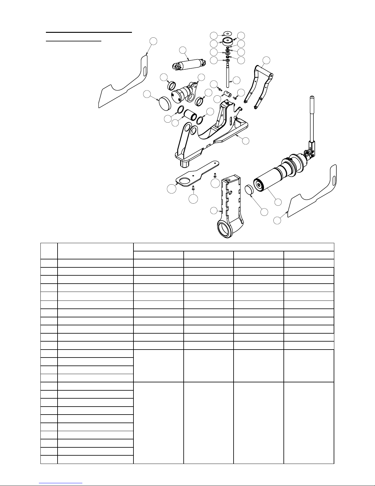
ITEM
NO.
DESCRIPTION
PART NO.
TFA12TI TFA15TI TFA12TIRD37H TFA15TIRD37H
1 WING ARM_WELDED ASSEMBLY 1210100-01 270100-01 1210100-01 270100-01
2 BODY ASSEMBLY - WELDED 270200-01 270200-01 270200-01 270200-01
3 STRUT ASSEMBLY 270300-01 270300-01 270300-01 270300-01
4 CYLINDER ASSEMBLY 270500-01 270500-01 270500-01 270500-01
5 HANDLE ASSEMBLY 271300-01 271300-01 271300-01 271300-01
6 ADJUSTABLE LEG ASS 270400-01 270400-01 270400-01 270400-01
7 ADJUSTMENT LEG FIXING SHAFT 270900-01 270900-01 270900-01 270900-01
8 SIDE SPACER BUSH 272000-01 272000-01 272000-01 272000-01
9 SPIRAL CLIP 270800-01 270800-01 270800-01 270800-01
10 RHS STICKER 1700002-01 070393-01 1680005-01 1690002-01
11 LHS STICKER 1700001-01 070392-01 1680004-01 1690001-01
13 PROTECTION PAD
KIT
271400-01
KIT
271400-01
KIT
271400-01
KIT
271400-01
14 M6 CSK HEX SCREW
15 FOOT CAP FLANGE
16 FOOT CAP TOWER
17 ADJUSTMENT ROD
KIT
271500-01
KIT
271500-01
KIT
271500-01
KIT
271500-01
18 ADJUSTER BOSS
19 ADJUSTMENT BUSH
20 ADJUSTMENT BUSH WASHER
21 WING ADJUST DECAL
22 RELEASE KNOB
23 10MM EXTERNAL CIRCLIP
24 WASHER 10mm ID
25 M5 SCKT SET SCREW
26 M5x12mm SCKT HEAD CPSCREW
TFA15TI PARTS LIST
270000-01 REV.01
10
8
3
16
9
7
9
8
6
26
18
5
25
17
23
24 19
20 24
22
21
26
2
1
15
4
11
13
14
14
Page 16
3
1
5
2
3
6
4
7
7
7
7
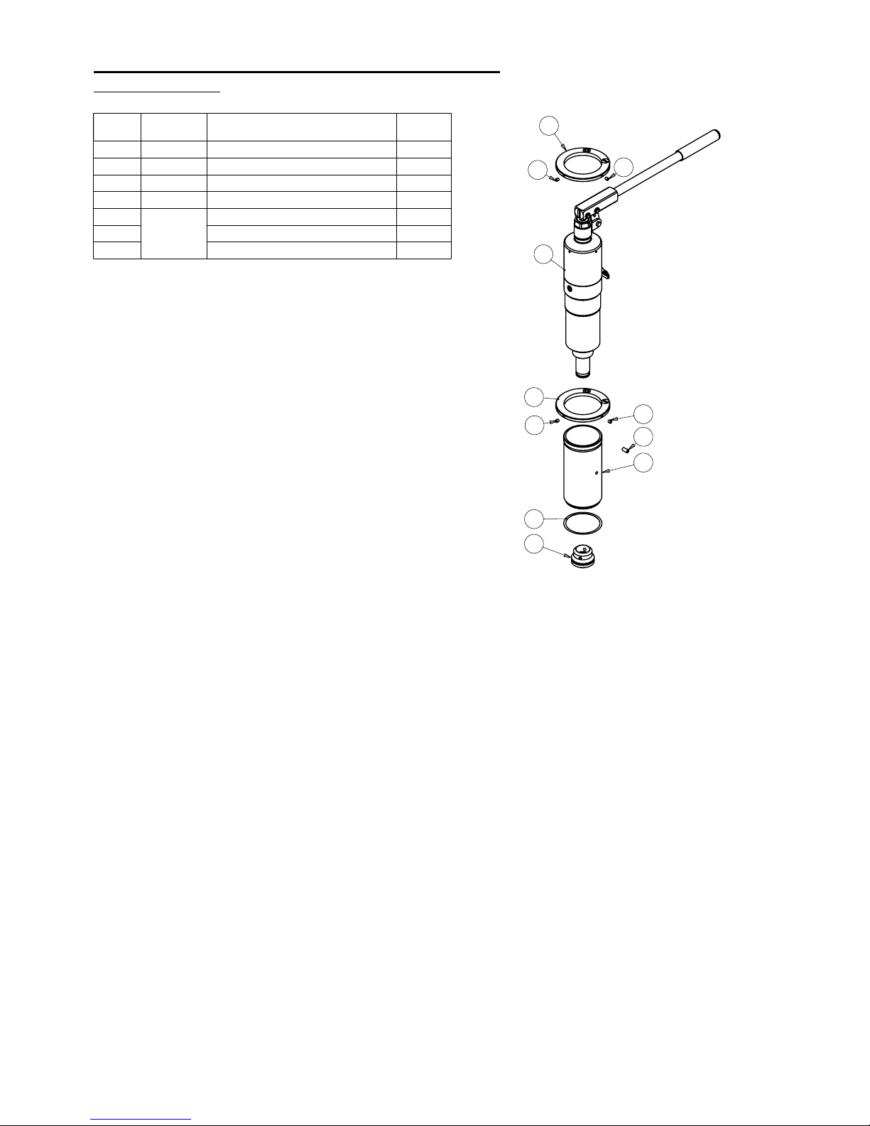
ITEM
NO.
PART NO
DESCRIPTION
QTY/ASS
1
840300-01
H.CYLINDER & PUMP TI ASSEMBLY
1
2
270600-01
CYLINDER FOOT ASSEMBLY
1
3
270701-01
CYLINDER ADJUSTING RING
2
4
270501-01
TI CYLINDER SLEEVE
1
5
KIT
271900-01
SPIRAL RETAINING RING
2
6
M6 SCKT SET SCREW
1
7
M5 SCKT SET SCREW
4
TFA15TI CYLINDER ASSEMBLY PARTS LIST
270500-01 REV.01
Page 17
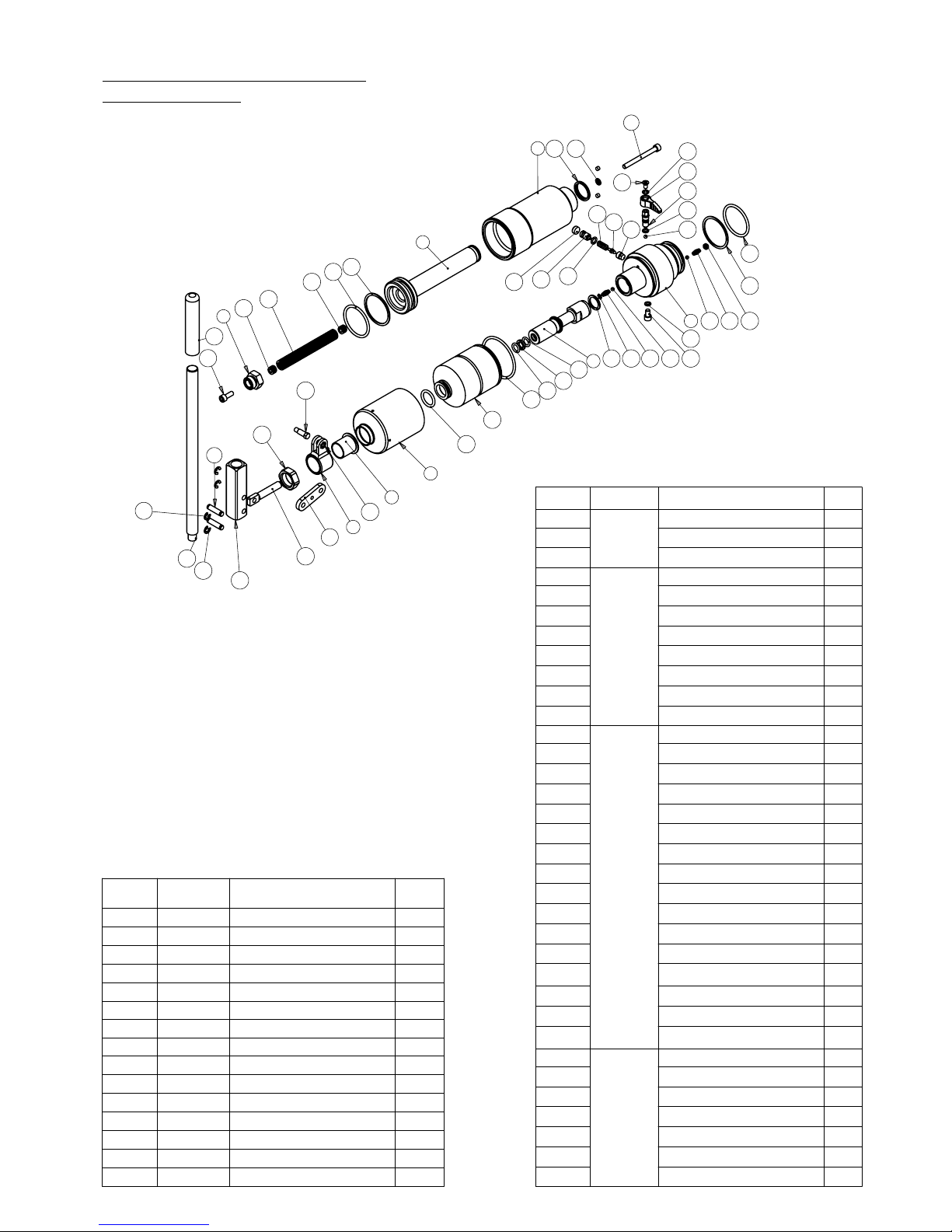
25
4
21
21
23
24
3
1
19 26
22
23
24
4742 465
31
27
42464835
6
36
37
36
40
38
39
7
8
9
11
10
12
13
41
16
18
18
14
15
33
32
34
45
44
43 42
27
28
29
27
30
20
17
ITEM NO.
PART NO
DESCRIPTION
QTY.
16
KIT
840160-01
HANDLE CLEVIS
1
17
CLEVIS PIN
2
18
RETAINING RING
4
19
KIT
840110-01
WIPER SEAL
1
20
TENSION DIE SPRING
1
21
SPRING LOCK
2
22
M6 CAPSCREW
1
23
O-RING
2
24
BACK-UP RING
2
25
SCREW
1
26
M6 GASKET SEAL
1
27
KIT
840120-01
O-RING
3
28
RELIEF VALVE SCREW
1
29
RELIEF VALVE KNOB
1
30
FIXING SCREW
1
31
OIL FILL SCREW
1
32
OVERLOAD COVER SCREW
1
33
CAP
1
34
O-RING
1
35
WASHER
1
36
O-RING
2
37
BACK UP RING
1
38
RESERVOIR BLADDER
1
39
O-RING
1
40
O-RING
1
41
PUMP PISTON ROD
1
42
STEEL BALL
1
43
KIT
375020-01
STEEL BALL
2
44
CONE SEAT
1
45
CONE
1
46
LONG SEPARATOR SPRING
1
47
SPRING
2
48
SCREW
1
49
SPRING LOCK
1
ITEM NO.
PART NO
DESCRIPTION
QTY.
1
830301-01
CYLINDER BODY
1
2
830310-01
CYL VENT PLUG
2
3
830302-01
PISTON
1
4
840100-01
NUT
1
5
840301-01
CYLINDER BASE
1
6
376901-01
PUMP PISTON HOUSING
1
7
840302-01
BLADDER HOUSING
1
8
372401-01
PISTON HOUSING CAP
1
9
372501-01
SWIVEL CLEVIS
1
10
373201-01
CLEVIS SCREW
1
11
373301-01
ANTI-LOOSEN NUT
1
12
373101-01
LINK CONNECTOR
1
13
372601-01
RETAINING NUT
1
14
373401-01
HANDLE ROD
1
15
306502-01
HANDLE GRIP
1
TI CYLINDER PARTS LIST
840300-01 REV.02
Page 18
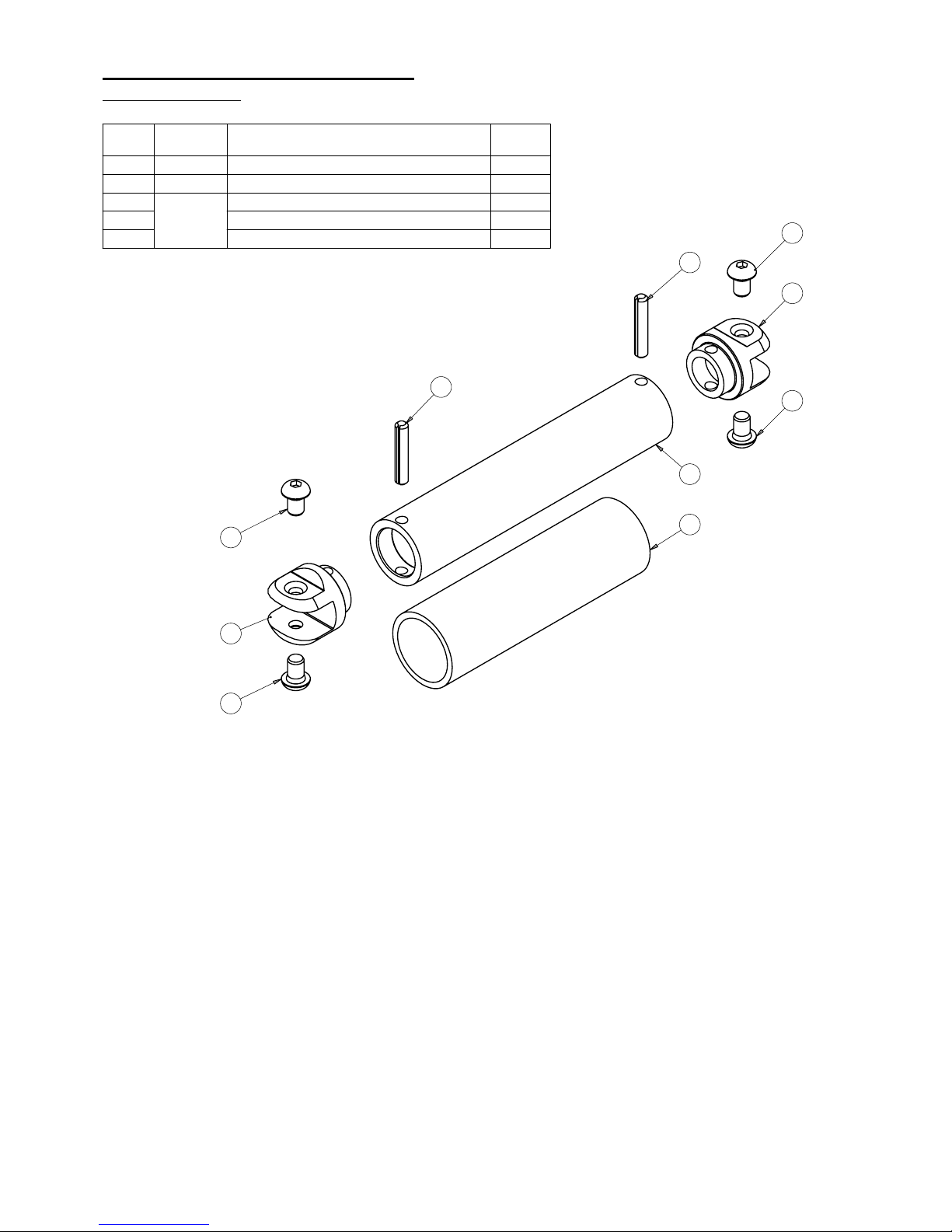
3
2
3
5
4
1
5
3
2
3
ITEM
NO.
PART NO
DESCRIPTION
QTY/ASS
1
270301-09
STRUT TUBE
1
2
270302-09
CLEVIS
2
3
KIT
271600-01
M8 BUTTON HEX SCREW
4
4
FOAM GRIP - 34MM X 135MM
1
5
6MM ROLL PIN
2
STRUT ASSEMBLY PARTS LIST
270300-01 REV.01
Page 19
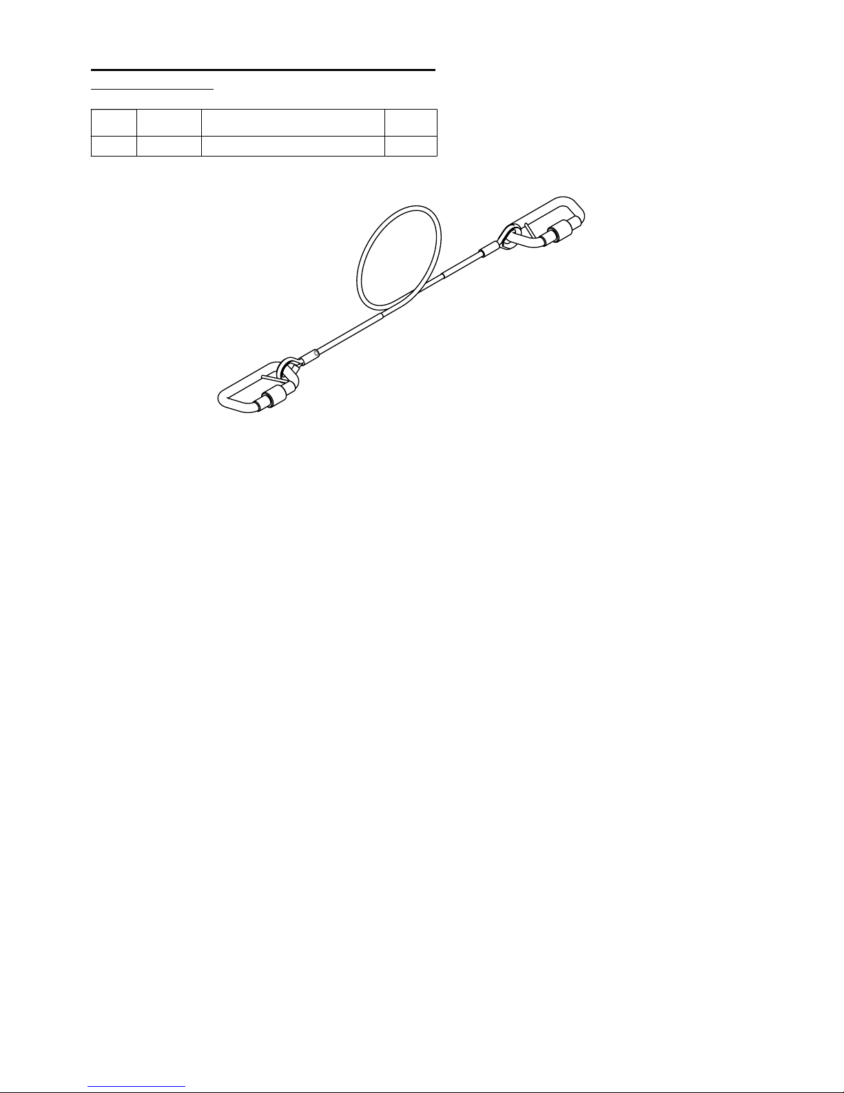
ITEM
NO.
PART NO
DESCRIPTION
QTY/ASS
1
270800-01
SAFETY BOND ASSEMBLY
1
SAFETY BOND ASSEMBLY PARTS LIST
270800-01 REV.01
Page 20
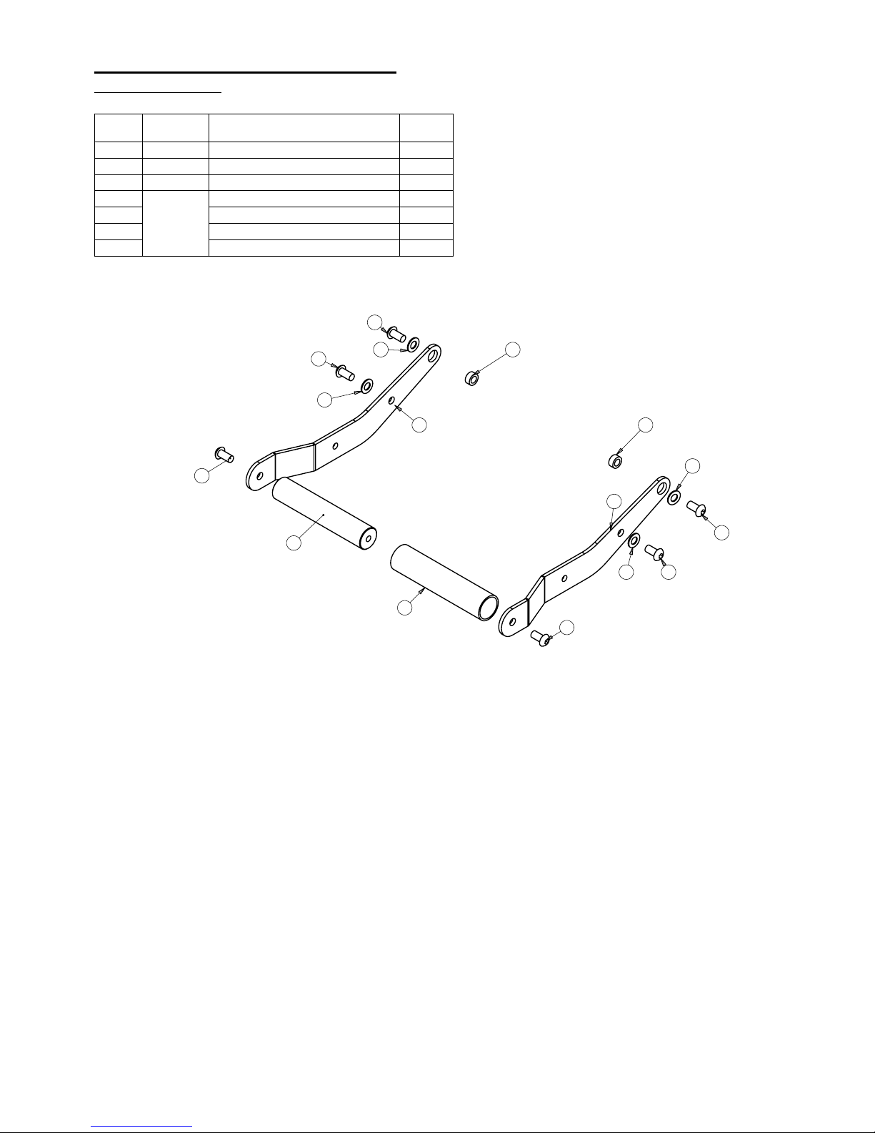
6
6
5
3
1
4
2
5 6
6
5
6
6
5
7
7
ITEM
NO.
PART NO
DESCRIPTION
QTY/ASS
1
501301-01
HANDLE BAR
1
2
501101-01
HANDLE LEFT
1
3
501201-01
HANDLE RIGHT
1
4
KIT
271800-01
BLUE HANDLE SLEEVE
1
5
WASHER (0.8MM)
6
6
SCREW FOR HANDLE
6
7
SPACER
2
HANDLE ASSEMBLY PARTS LIST
271300-01 REV.01
Page 21
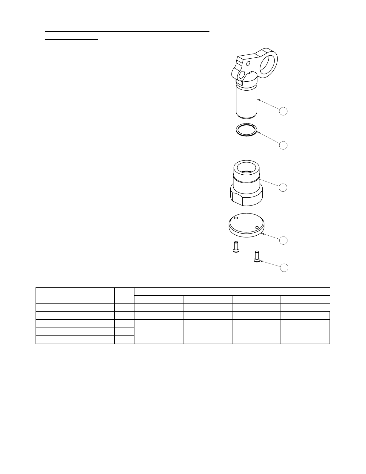
ITEM
NO.
DESCRIPTION
QTY/
ASS
PART NO.
TFA12TI TFA15TI TFA12TIRD37H TFA15TIRD37H
1 CLEVIS WELDED ASSEMBLY 1 270401-01 270401-01 1690201-01 1690201-01
2 ADJUSTMENT FOOT 1 270402-01 270402-01 270402-01 270402-01
3 ADJUSTMENT FOOT PAD 1
KIT
271700-01
KIT
271700-01
KIT
271700-01
KIT
271700-01
4 SPIRAL CLIP 1
5 M6 CSK HEX SCREW 2
4
2
5
3
1
ADJUSTMENT LEG ASSEMBLY PARTS LIST
270400-01 REV.01
Page 22
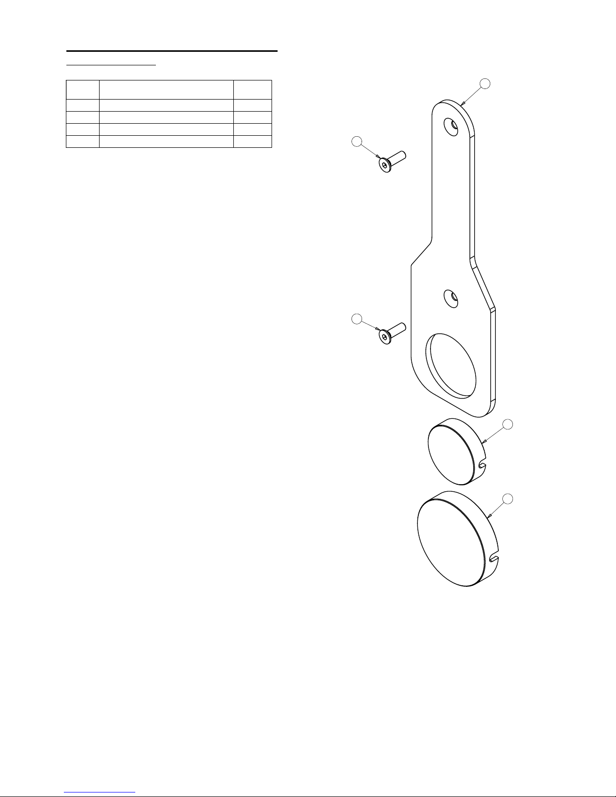
4
3
2
1
1
ITEM
NO.
DESCRIPTION
QTY/ASS
1
M6 CSK HEX SCREW
2
2
FOOT CAP TOWER
1
3
FOOT CAP FLANGE
1
4
PROTECTION PAD
1
PROTECTIVE PAD SERVICE KIT
271400-01 REV.01
Page 23
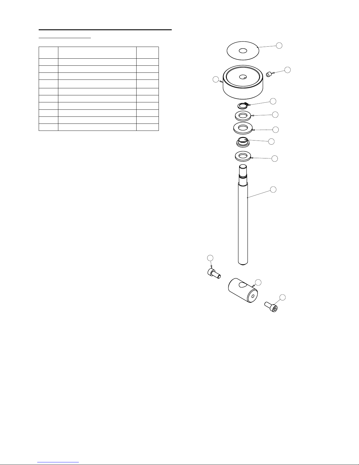
5
9
7
8
4
3
8
1
2
10
10
6
ITEM
NO.
DESCRIPTION
QTY/ASS
1
ADJUSTMENT ROD
1
2
ADJUSTER BOSS
1
3
ADJUSTMENT BUSH
1
4
ADJUSTMENT BUSH WASHER
1
5
WING ADJUST DECAL_TFA15TI
1
6
RELEASE KNOB
1
7
10MM EXTERNAL CIRCLIP
1
8
WASHER 10mm ID
2
9
M5 SCKT SET SCREW
4
10
M5x12mm SCKT HEAD CPSCREW
2
WING ADJUSTMENT SERVICE KIT
271500-01 REV.01
Page 24
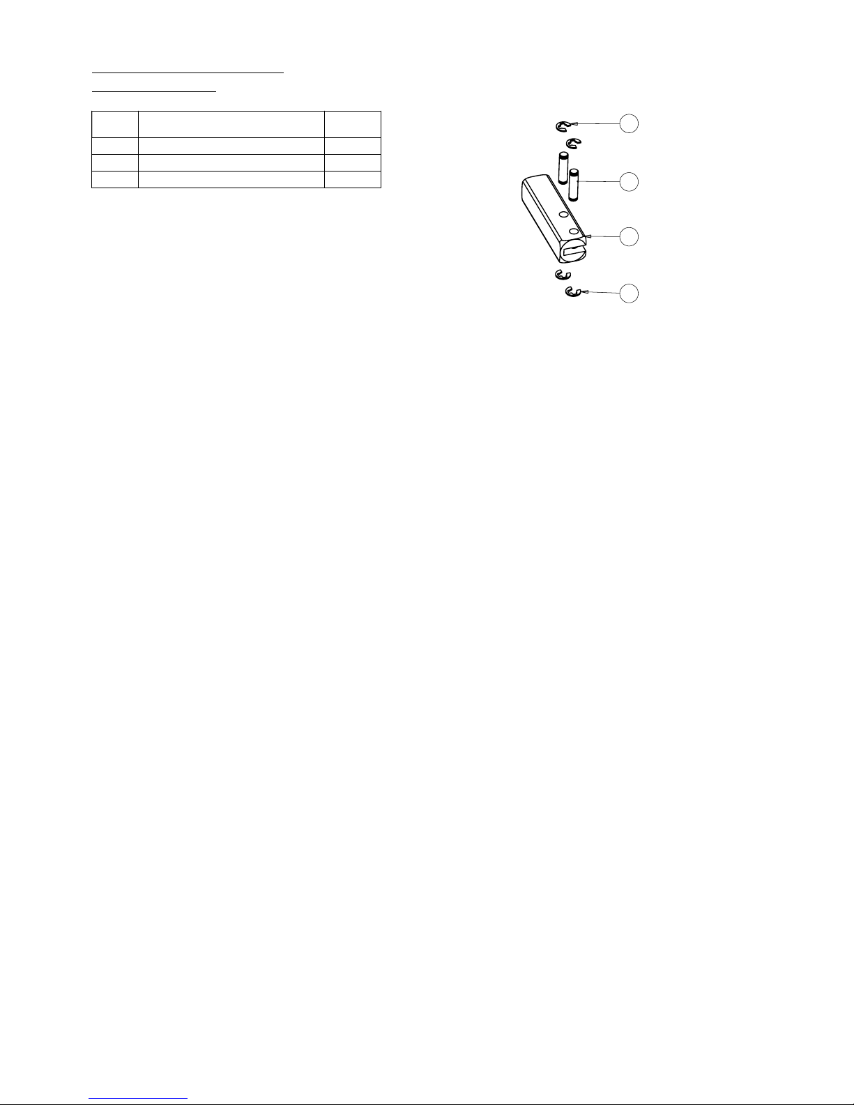
3
2
1
3
ITEM
NO.
DESCRIPTION
QTY
1
HANDLE CLEVIS
1
2
CLEVIS PIN
2
3
RETAINING RING
4
CLEVIS SERVICE KIT
840160-01 REV.01
Page 25
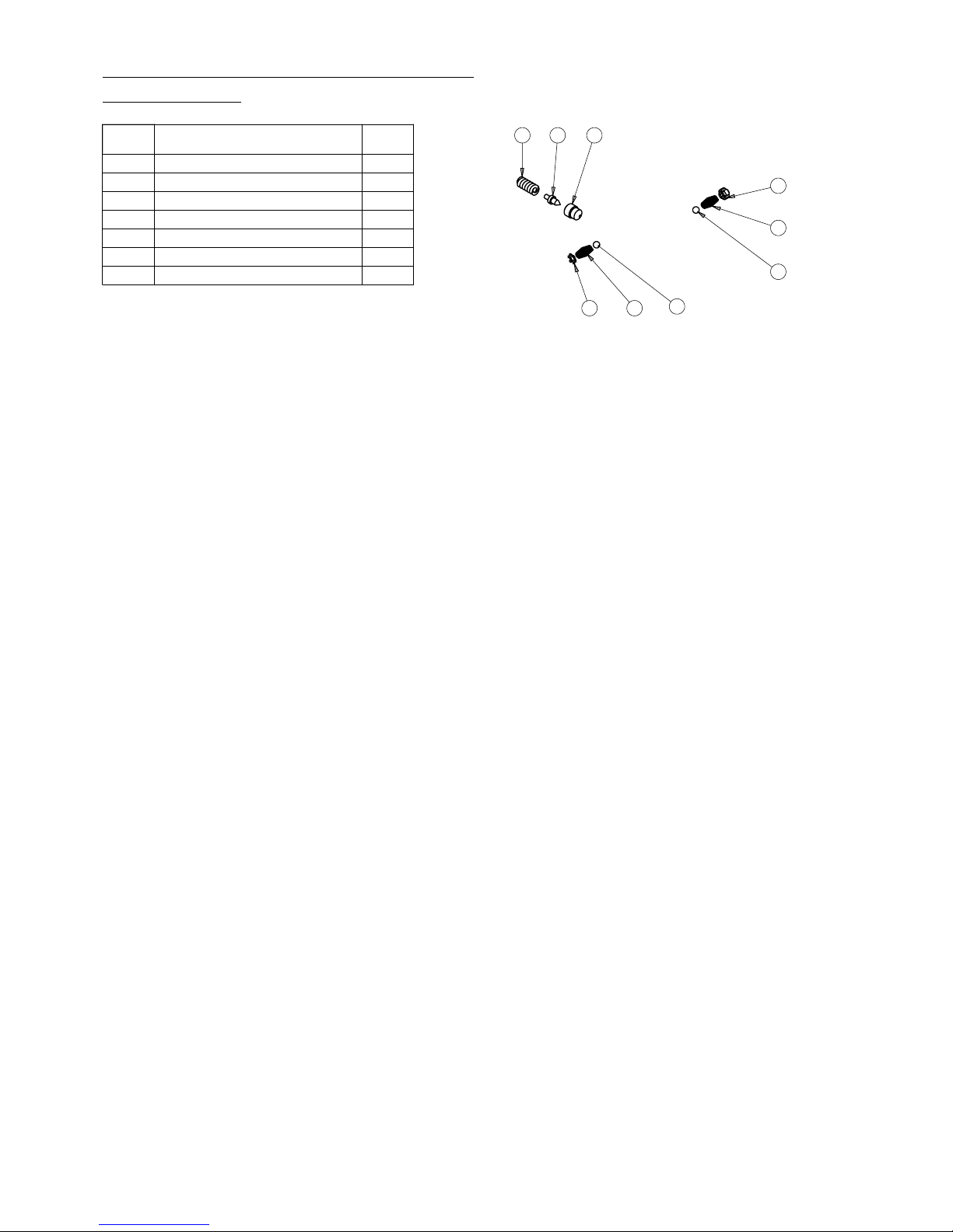
4 3 2
7 5
1
1
6
5
ITEM
NO.
DESCRIPTION
QTY.
1
STEEL BALL
2
2
CONE SEAT
1
3
CONE
1
4
LONG SEPARATOR SPRING
1
5
SPRING
2
6
SCREW
1
7
SPRING LOCK
1
INTEGRAL MANIFOLD SERVICE KIT
375020-01 REV.01
Page 26
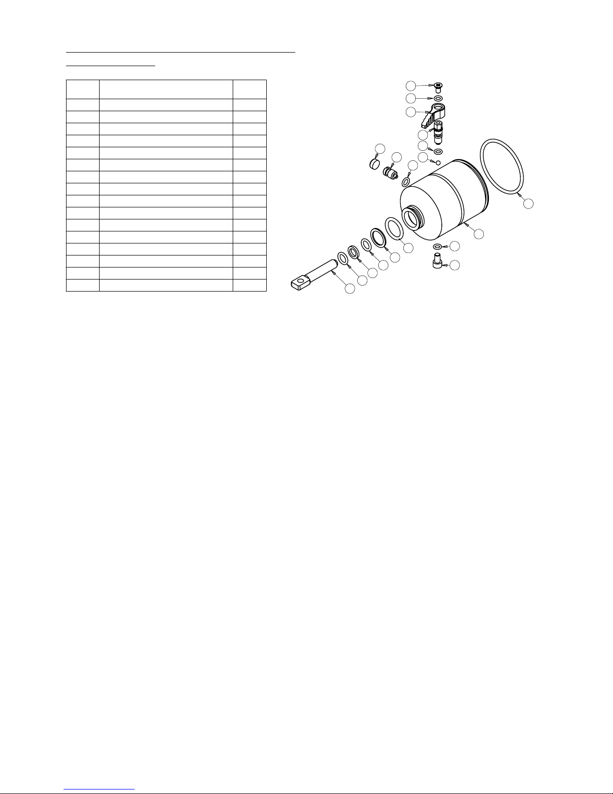
5
2
4
3
2
1
8
7
9
16
15
2
6
13
14
11
12
11
10
ITEM
NO.
DESCRIPTION
QTY.
1
STEEL BALL
1
2
O-RING
3
3
RELIEF VALVE SCREW
1
4
RELIEF VALVE KNOB
1
5
FIXING SCREW
1
6
OIL FILL SCREW
1
7
OVERLOAD COVER SCREW
1
8
CAP
1
9
O-RING
1
10
WASHER
1
11
O-RING
2
12
BACK UP RING
1
13
O-RING
1
14
PUMP PISTON ROD
1
15
RESERVOIR BLADDER
1
16
O-RING
1
INTEGRAL BLADDER SERVICE KIT
840120-01 REV.02
Page 27
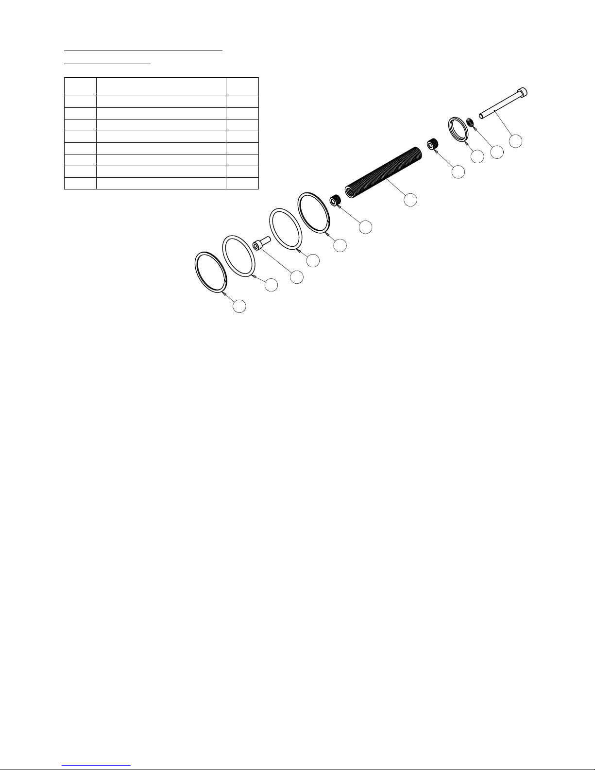
4
8
1
3
2
3
6
5
7
5
6
ITEM
NO.
DESCRIPTION
QTY.
1
WIPER SEAL
1
2
TENSION DIE SPRING
1
3
SPRING LOCK
2
4
M6 CAPSCREW
1
5
O-RING
2
6
BACK-UP RING
2
7
SCREW
1
8
M6 GASKET SEAL
1
CYLINDER SERVICE KIT
840110-01 REV.02
Page 28

EQUALIZER INTERNATIONAL LTD.
Head Office
Equalizer House
Claymore Drive
Aberdeen
Scotland
UK
AB23 8GD
t: +44 (0) 1224 701970
f: +44 (0) 1224 823791
Houston Office
1330 Yale Street
Houston TX 77008
USA
t: +1 (713) 927-1840
www.equalizerinternational.com
 Loading...