

Page 1
OPERATOR INSTRUCTION MANUAL
MG7TM
MINI GAP
FLANGE SPREADER
EQUALIZER INTERNATIONAL LTD
www.equalizerinternational.com
Page 2

OPERATOR INSTRUCTION MANUAL
CONTENTS
1. INTRODUCTION
2. TOOL SAFETY
2.1 GENERAL SAFETY
2.2 PERSONNEL COMPETENCY
2.3 DISCLAIMER
2.4 DEFINITION OF TERMS
2.5 HAZARDS
3. MG7TM MINI GAP FLANGE SPREADER
3.1 TOOL CAPABILITIES
3.2 TOOL FUNCTION
3.3 KIT CONTENTS
3.4 TOOL DIMENSIONS
3.5 TOOL MAINTENANCE
4. RANGE OF APPLICATION
4.1 ASME
BLIND FLANGES
4.2 ASME B16.5 SOCKET WELDED
4.3 ASME B16.5 LONG WELDING NECK FLANGE
4.4 ASME B16.5 LAPPED FLANGE
4.5 ASME B16.47 WELDNECK AND BLIND FLANGES
4.6 ANSI REDUCING
4.7 ANSI ORIFICE - WELDNECK FLANGE
4.8 ANSI ORIFICE - SLIP-ON AND THREADED FLANGES
4.9 BS
B16.5 WELDNECK, THREADED, SLIP-ON AND
IM_MG7TMSTD_Rev09
5. REGULATORY INFORMATION
5.1 REGISTERED HEAD OFFICE
6. PARTS LISTS & SERVICE KITS
01/02/2019
MG7TM
1
MINI GAP FLANGE SPREADER
Page 3

OPERATOR INSTRUCTION MANUAL
IM_MG7TMSTD_Rev09
1.
INTRODUCTION
The Equalizer MG7TM MINI-GAP FLANGE SPREADER is
designed to aid the safe separation of ange faces. This
system has a unique ability to break ange joints with a
2mm gap between the ange faces. The tool is designed
to separate anges while applying an immense amount of
force to the correct point of separation.
The use of these instructions will promote safe use, and
maximise the service life of the tools.
It is essential that the user familiarises themselves with
the contents of this manual prior to using the tool.
This manual contains information for the following tools:
• MG7TM Mini-Gap Flange Spreader
The Equalizer MG7TM Mini-Gap Flange Spreader:
• Offers a safe and reliable working method
• Provides 6.8 tonnes of spreading force
• Separates ange faces with a gap of 2mm or greater
• Is lightweight and easy to use
2.
SAFETY INFORMATION
2.1
GENERAL SAFETY
These instructions cover the safe operation and
maintenance of THE EQUALIZER MG7TM MINI GAP
FLANGE SPREADING tools. The use of these tools should
be as part of a broader task-based risk assessment, which
should be carried out by the operation supervisor or other
competent person.
Failure to comply with the safety information contained
within this manual could result in personal injury or
equipment damage. Read all instructions, warnings and
cautions carefully, and follow all safety precautions.
The safety of the operator, any assisting personnel and
the general public is of paramount importance. Always
work in accordance with applicable national, local, site &
company-wide safety procedures.
2.2
PERSONNEL COMPETENCY
Only personnel deemed competent in the use of mechanical
and hydraulic equipment should use these tools.
2.3
DISCLAIMER
Equalizer cannot be held responsible for injury or damage
resulting from unsafe product use, lack of maintenance
or incorrect product and/or system operation. If in doubt
as to the safety precautions and applications, contact
Equalizer using the contact details at the back of this
manual.
MG7TM
2
MINI GAP FLANGE SPREADER
Page 4

OPERATOR INSTRUCTION MANUAL
IM_MG7TMSTD_Rev09
2.4
DEFINITION OF TERMS
A CAUTION is used to indicate correct operating or
maintenance procedures and practices to prevent damage
to, or destruction of equipment or other property.
A WARNING indicates a potential danger that requires correct
procedures or practices to avoid personal injury.
A DANGER is only used when your action or lack of action
may cause serious injury or even death.
DO: an illustration showing how the tool should
be used.
DON’T: an illustration showing an incorrect way to
use a tool.
WARNING: Applying pressure to a damaged hose
may cause it to rupture.
WARNING: Immediately replace worn or damaged
parts. Use only genuine Equalizer parts from
approved distributors or service centres. Equalizer
parts have been engineered and manufactured to
be t-for-purpose.
DANGER: To minimise risk of personal injury keep
hands and feet away from the tool and workpiece
during operation.
WARNING: Always wear suitable clothing and
Personal Protective Equipment (PPE). Do not
handle pressurised hoses; escaping oil under
pressure can penetrate the skin, causing serious
injury. Seek medical attention immediately if oil
penetration is suspected.
WARNING: Only pressurize complete and fully
connected hydraulic systems. Do not pressurize
systems that containt unconnected couplers.
2.5
HAZARDS
WARNING: ensure all hydraulic components are
rated to a safe working pressure of 700bar
(10,000psi).
WARNING: Do not overload equipment. The risk of
hydraulic overloading can be minimised by using
the Equalizer Hand Pump, which has a factory-set
safety valve preventing the safe working pressure
being exceeded.
If alternative hydraulic pumps are used, ensure
that there are adequate systems to limit the
working pressure to 700 bar (10,000 psi).
CAUTION: ensure components are protected from
external sources of damage, such as excessive
heat, ame, moving machine parts, sharp edges
and corrosive chemicals.
CAUTION: Take care to avoid sharp bends and
kinks in hydraulic hoses. Bends and kinks can
cause severe back-up pressure and cause hose
failure. Protect hoses from dropped objects; a
sharp impact may cause internal damage to hose
wire strands. Protect hoses from crush risks, such
as heavy objects or vehicles; crush damage can
cause hose failure.
CAUTION: Do not lift hydraulic equipment by the
hoses or couplers. Use only the designated carrying
handles.
CAUTION: Lubricate tools as directed in this
manual prior to operation. Use only approved
lubricants of high quality, following the lubricant
manufacturers instructions.
CAUTION: Only use the designated anchor point
for xing the lanyard. Do not attach the lanyard to
the plastic handle.
DANGER: Care should be taken when using the
lanyard to avoid entanglement with body parts.
MG7TM
3
MINI GAP FLANGE SPREADER
Page 5
OPERATOR INSTRUCTION MANUAL
3.
MG7TM
MINI GAP FLANGE
SPREADER
3.1
TOOL CAPABILITIES
Spreading Force: 6.8 T (68 kN) per tool
IM_MG7TMSTD_Rev09
3.2
MG7TM TOOL FUNCTION
INTRODUCTION
1. Select tool conguration
It is recommended that tools are used in pairs giving
2 x 6.8 = 13.6 T (136 kN)
The tool achieves a spreading distance of 27mm from
a 2mm gap. At a 7mm gap the tool steps down the
spreading force applied from 6.8 tonnes to 3.9 tonnes.
2. Tool assembly
3. Flange spreading
MG7TM
4
MINI GAP FLANGE SPREADER
Page 6
OPERATOR INSTRUCTION MANUAL
IM_MG7TMSTD_Rev09
INSTALLATION AND OPERATION
Before attaching the tool, ensure at least two
ange bolts remain in place, 180 degrees apart,
with nuts loosened sufciently enough for
ange work to be carried out. These bolts will
reduce lateral ange movement during ange
spreading and will help support the unit.
Do not extend the handle or use the smaller spreading bar
as an extension bar.
Be aware of the dangers of breaking sealed ange joints.
Ensure that relevant risk assessments have been carried
out for the task and your company procedures must be
followed at all times.
Choose the suitable conguration for the size and class of
ange joint you wish to separate.
See the application charts found at the end of of this
manual.
The spreading bars are designed to only t the correct
ange specication. No two spreading bars can t the
same stud hole.
The ange bolting should be disassembled as
per your company’s procedures and risk
assessment.
Place the tool over the ange joint and align with the
desired stud hole.
TOOL CONFIGURATION 1
Large
Ø 20mm (0.79”)
Spreading bar
TOOL CONFIGURATION 2
Small
Ø 16mm (0.63”)
Spreading bar
Engage the spreading bar through the leg of the
tool and the ange stud hole.
Do not hammer or use excessive force to t
the spreading bar. The bar should be tted by
hand.
MG7TM
5
MINI GAP FLANGE SPREADER
Page 7
OPERATOR INSTRUCTION MANUAL
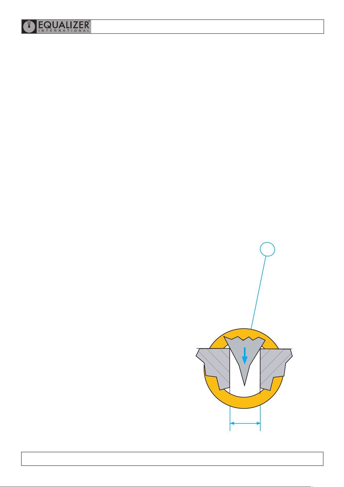
Take care to ensure the spreading bar is correctly tted
through the second leg of the tool. Check
the wedge is positioned in the gap between the
ange faces.
It is strongly recommended that two MG7TM Tools are
used on the ange joint positioned 180 degrees apart.
IM_MG7TMSTD_Rev09
FLANGE SPREADING AND SEAL REMOVAL
Turn each opposing tool a half turn at a time until the
desired gap is achieved. Care must be taken to ensure the
force is applied evenly.
FLANGE SEPARATION
The maximum spreading distance for the MG7TM is
27mm.
MG7TM
27mm
MAX
6
MINI GAP FLANGE SPREADER
Page 8
OPERATOR INSTRUCTION MANUAL
IM_MG7TMSTD_Rev09
3.3
MG7TM KIT CONTENTS
Product Code: MG7TMSTD
1 x MG7TM Tool
1 x Ø 16mm (0.63”) Spreading Bar
1 x Ø 20mm (0.79”) Spreading Bar
1 x Instruction Manual
1 x Carry Case
3.4
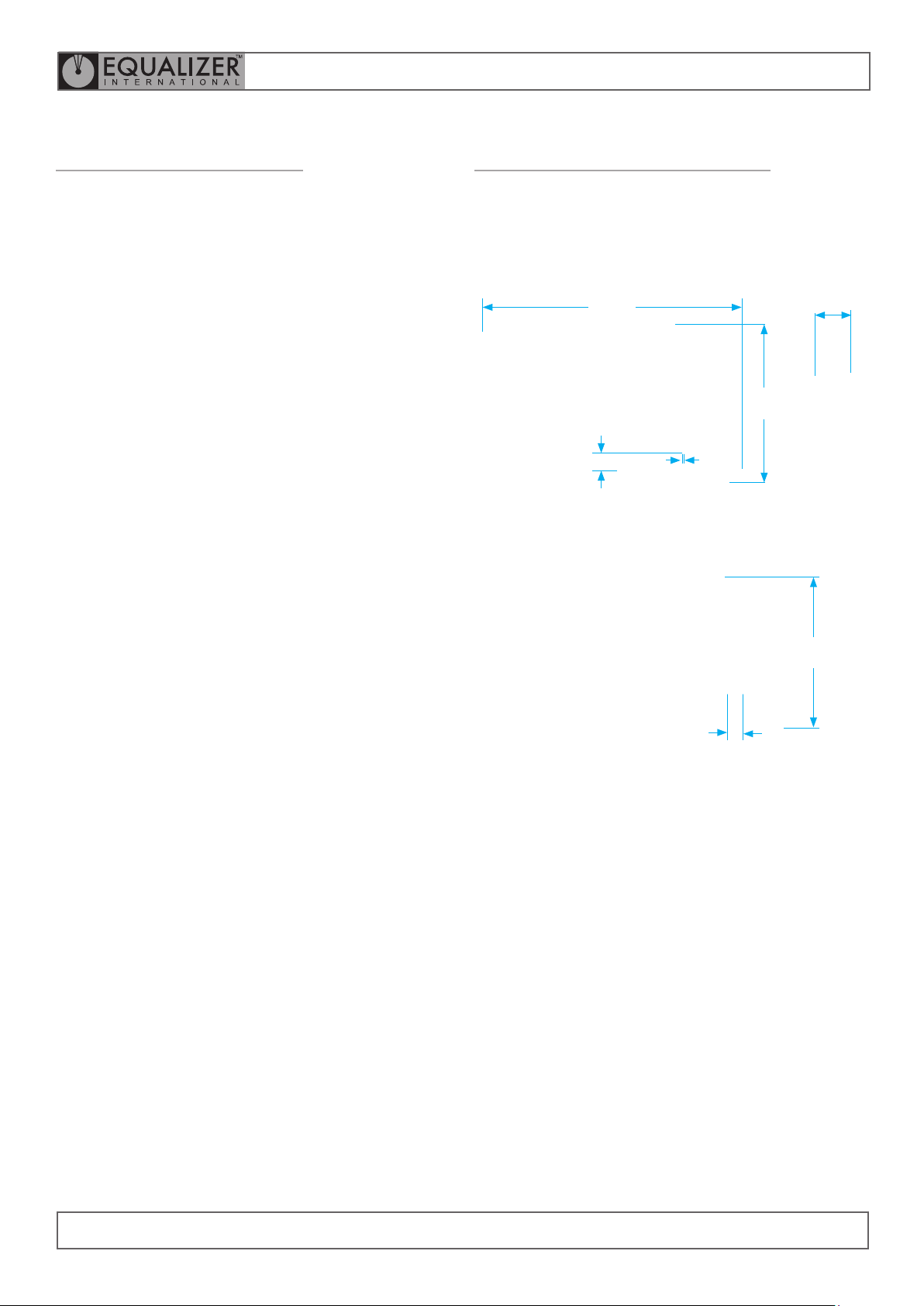
MG7TM TOOL DIMENSIONS
LARGE Ø20MM (0.79”) SPREADING BAR
TOOL CONFIGURATION 1 RETRACTED WEDGE:
395mm
(15.55”)
261mm
(10.28”)
2mm
34mm
(1.34”)
TOOL CONFIGURATION 1 ADVANCED WEDGE:
(0.08”)
50mm
(1.97”)
Carry Case Dimensions:
360mm x 300mm x 90 mm
(14.2” x 11.8” x 3.5”)
Tool only Weight: 5 kg (11.02 lb)
Gross Kit Weight: 5.5 kg (12.13 lb)
27mm
(1.06”)
227mm
(8.94”)
MG7TM
7
MINI GAP FLANGE SPREADER
Page 9
OPERATOR INSTRUCTION MANUAL
IM_MG7TMSTD_Rev09
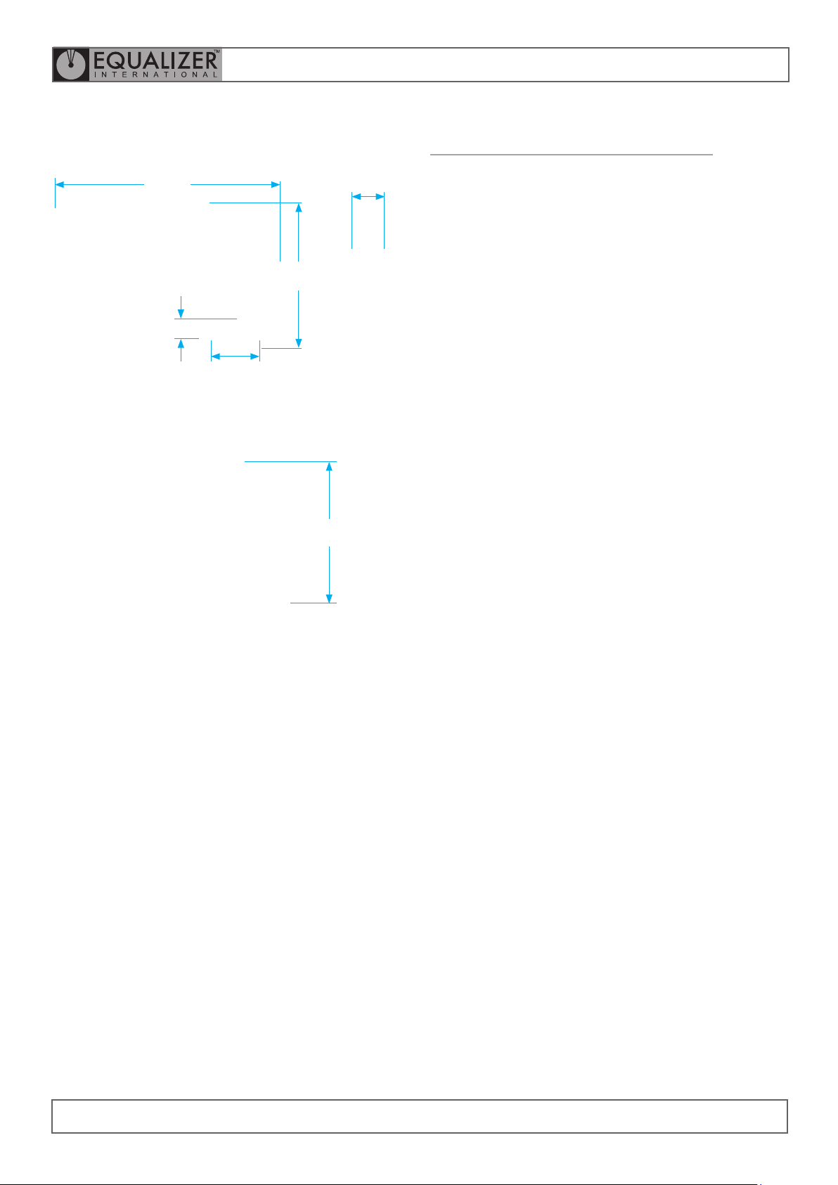
SMALL Ø16MM (0.63”) SPREADING BAR
TOOL CONFIGURATION 2 RETRACTED WEDGE:
365mm
(14.37”)
261mm
(10.28”)
34mm
(1.34”)
91mm
(3.58”)
TOOL CONFIGURATION 2 ADVANCED WEDGE:
227mm
(8.94”)
50mm
(1.97”)
3.5
MG7TM TOOL MAINTENANCE
INSPECTION
A thorough inspection should be carried out prior to usage,
storage or transportation to ensure the completeness and
condition of the tool.
Inspection should include:
• visual inspection of the outer parts of the tool,
checking for obvious damage, degradation or missing
parts.
Cleaning and servicing should be undertaken as required
prior to the tool being used, stored or transported.
CLEANING
At regular intervals, and specically after being exposed
to salt water, Mini-Gap mechanical tools should be
dismantled and lubricated as follows:
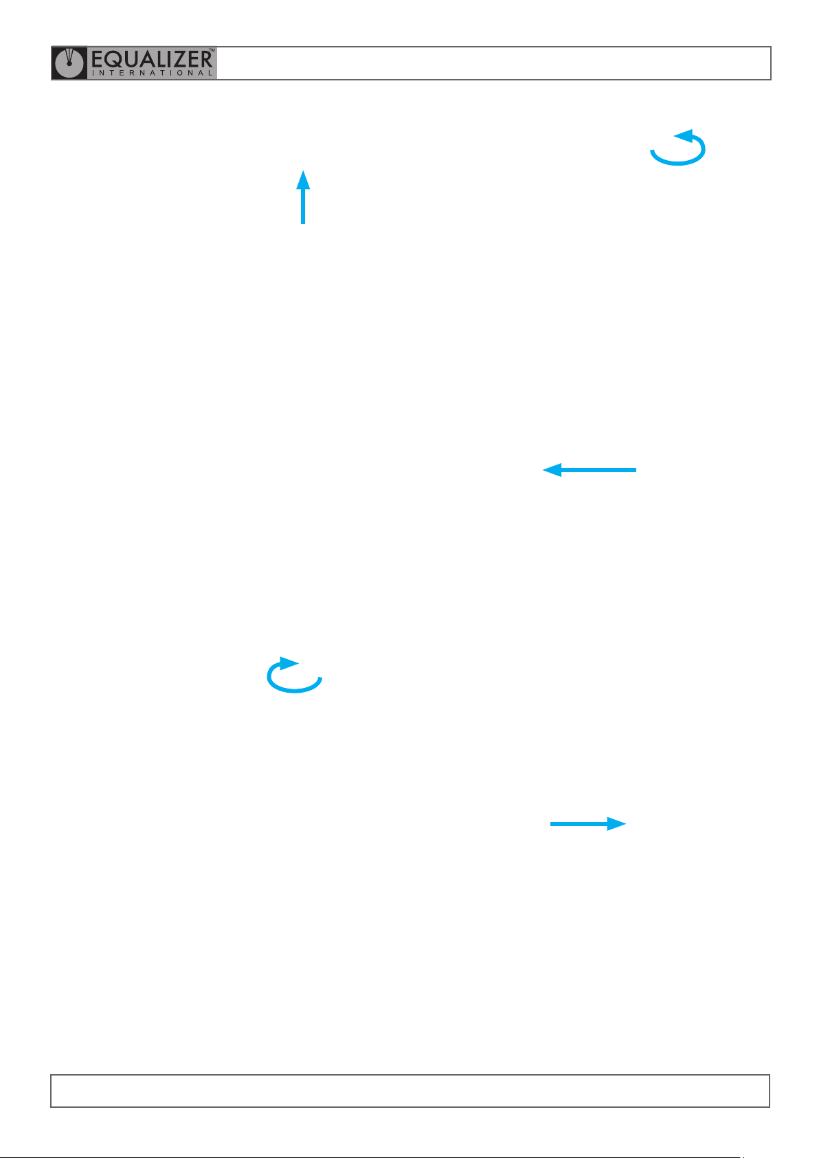
1. Lay the tool on a bench or at surface with the right
hand side face down.
2. Pull the spreading bar out of the tool.
MG7TM
8
MINI GAP FLANGE SPREADER
Page 10
OPERATOR INSTRUCTION MANUAL
IM_MG7TMSTD_Rev09
3. To Remove the left hand cast leg from the tool.
Pull the spring loaded plunger to release the leg.
4. Remove the right hand cast leg from the tool.
6. Fully unscrew the drive screw. Remove the main body
and the outer sleeve from the tool.
5. Drive the handle so that the splitter wedge moves
down. Then remove the Splitter wedge and Thrust
bearing from the tool.
7. Apply grease to the drive screw.
Clean all components and inspect for wear and
damage. Replace missing, worn or damaged parts.
Use only genuine Equalizer parts from approved
distributors or service centres. Equalizer parts have
been engineered and manufactured to be t for
purpose.
MG7TM
9
MINI GAP FLANGE SPREADER
Page 11

OPERATOR INSTRUCTION MANUAL
IM_MG7TMSTD_Rev09
8. Reassemble by reversing the disassembly
procedure (steps 2 to 7).
Note: it is recommended that the tool is
wiped down with a clean rag and WD40 or
similar cleaning uid to remove any dirt or
grit and then liberally greased with a high
load bearing grease (Rocol sapphire high load
2 or similar)
6. Once bags have been closed and sealed DO NOT re-
open. Any visual inspections must be done with closed
and sealed bags. If bags are opened the components
will have to be dried, re-coated and re-sealed in bags/
shrink wrap.
7. Replace silica gel (100g) EVERY TIME the case is
opened.
NOTE: depending on moisture content of air, silica gel
should be changed weekly.
8. Visually inspect kits after 30-days and every 30-days
thereafter. Remember to replace silica gel before
closing case.
STORAGE AND TRANSPORTATION
Equalizer tools should be stored in a cool, dry place. Tools
should always be cleaned, serviced and lubricated prior to
storage. Ensure that tools are stored in their designated
packing cases.
LONG-TERM STORAGE - MAINTENANCE PLAN
1. Rub components down with a dry cloth to remove
moisture.
2. Coat EVERY surface and contact point with a corrosion
inhibitor. Where necessary, coat inside and outside of
component
3. Nuts and threads must also be coated with a corrosion
inhibitor.
4. Once surfaces have been coated, seal individual
components in clear plastic bags or clear vacuum
bags or clear shrink wrap.
NOTE: bags/shrink wrap must be clear for visibility.
Take care when using shrink wrap that the tool is/
components are still easy to see.
5. Remove all or, where not vacuum sealed, as much air
from bags as possible.
MG7TM
10
MINI GAP FLANGE SPREADER
Page 12
OPERATOR INSTRUCTION MANUAL
4.
RANGE OF APPLICATION
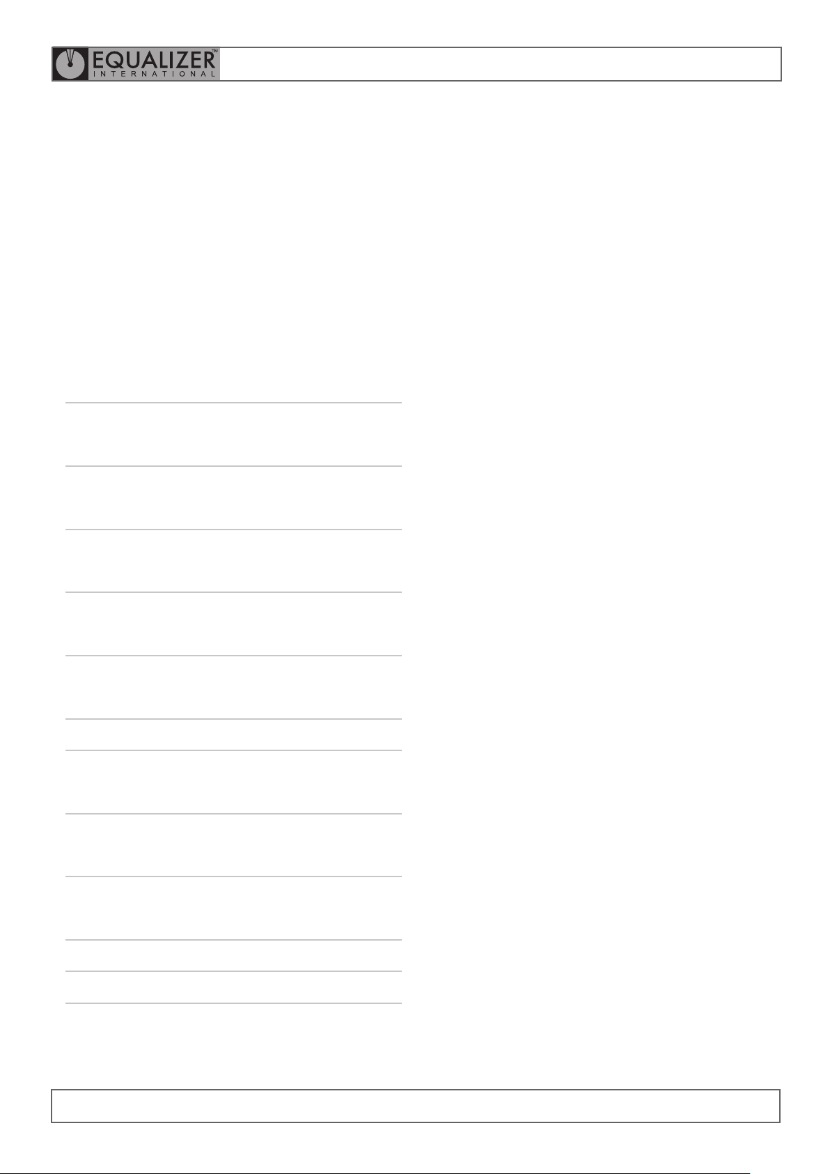
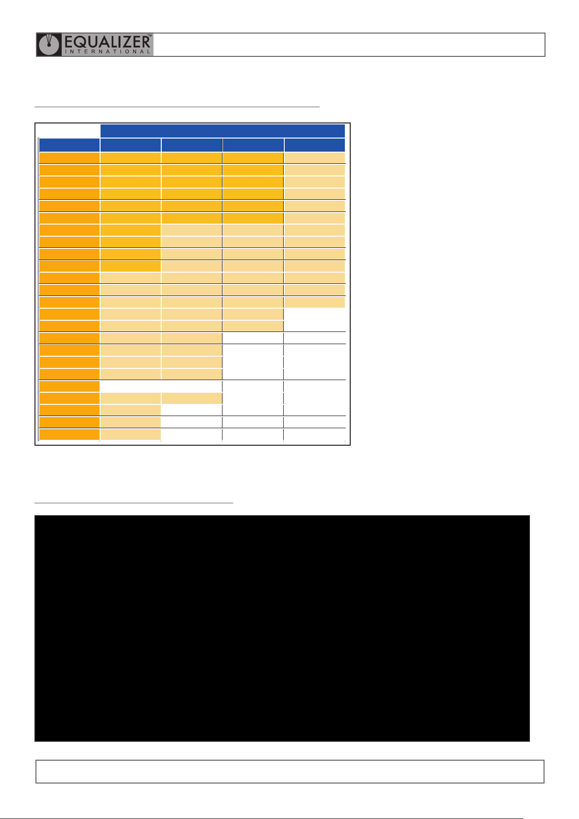
Use the charts on the following pages to determine
which spreading bar is suitable for a particular
ange.
The charts are categorised as per ange type.
IM_MG7TMSTD_Rev09
ASME B16.5 Weldneck,
Threaded, Slip-on
and Blind anges
B16.5 Socket
welded
B16.5 Long weld-
ing neck ange
B16.5 Lapped
ange
B16.47 Weldneck
and Blind anges
ANSI Reducing
Orice - Weldneck
ange
see secion 4.1
see secion 4.2
see secion 4.3
see secion 4.4
see secion 4.5
see secion 4.6
see secion 4.7
TOOL CONFIGURATION 1
Large
Ø 20mm (0.79”)
Spreading bar
TOOL CONFIGURATION 2
Small
Ø 16mm (0.63”)
Spreading bar
BS
MG7TM
Orice - Slip-on
and Threaded
anges
see secion 4.8
see secion 4.9
11
MINI GAP FLANGE SPREADER
Page 13

OPERATOR INSTRUCTION MANUAL
IM_MG7TMSTD_Rev09
4.1
ASME B16.5 WELDNECK, THREADED, SLIP-ON AND BLIND FLANGES
4.2
ASME B16.5 SOCKET WELDED FLANGE
MG7TM
12
MINI GAP FLANGE SPREADER
Page 14
OPERATOR INSTRUCTION MANUAL
Small Bar Small Bar Small Bar Large Bar
Small Bar Small Bar Small Bar Large Bar
Small Bar Small Bar Small Bar Large Bar
Small Bar Small Bar Small Bar Large Bar
Small Bar Small Bar Small Bar Large Bar
Small Bar Small Bar Small Bar Large Bar
Small Bar Large Bar Large Bar Large Bar
Small Bar Large Bar Large Bar Large Bar
Small Bar Large Bar Large Bar Large Bar
Small Bar Large Bar Large Bar Large Bar
Large Bar Large Bar Large Bar Large Bar
Large Bar Large Bar Large Bar Large Bar
Large Bar Large Bar Large Bar Large Bar
Large Bar Large Bar Large Bar
Large Bar Large Bar Large Bar
Large Bar Large Bar
Large Bar Large Bar
Large Bar Large Bar
Large Bar Large Bar
Large Bar Large Bar
Large Bar
Large Bar
Large Bar
4.3
ASME B16.5 Long welding neck flange
Class
NPS
1/2"
3/4"
1"
1 1/4"
1 1/2"
2"
2 1/2"
3"
3 1/2"
4"
5"
6"
8"
10"
12"
14"
16"
18"
20"
22"
24"
26"
28"
30"
150 300 600 900
IM_MG7TMSTD_Rev09
4.4
ASME B16.5 Lapped flange
MG7TM
13
MINI GAP FLANGE SPREADER
Page 15

OPERATOR INSTRUCTION MANUAL
4.5
ASME B16.47 Weldneck and blind flanges
4.6
IM_MG7TMSTD_Rev09
ANSI Reducing
MG7TM
14
MINI GAP FLANGE SPREADER
Page 16

OPERATOR INSTRUCTION MANUAL
4.7
ANSI Orifice - Weldneck flange
IM_MG7TMSTD_Rev09
4.8
ANSI Orifice - Slip-on and Threaded flanges
MG7TM
15
MINI GAP FLANGE SPREADER
Page 17

4.9
BS 10
OPERATOR INSTRUCTION MANUAL
IM_MG7TMSTD_Rev09
MG7TM
16
MINI GAP FLANGE SPREADER
Page 18

OPERATOR INSTRUCTION MANUAL
IM_MG7TMSTD_Rev09
5.
REGULATORY
INFORMATION
5.1
REGISTERED HEAD OFFICE
EQUALIZER INTERNATIONAL LTD.
Equalizer House
Claymore Drive
Aberdeen
Scotland
AB23 8GD
6.
PARTS LISTS
& SERVICE KITS
MG7TM
17
MINI GAP FLANGE SPREADER
Page 19
MG7TM MINI GAP
FLANGE SPREADER
OPERATOR INSTRUCTION MANUAL
IM_MG7TMSTD_Rev09
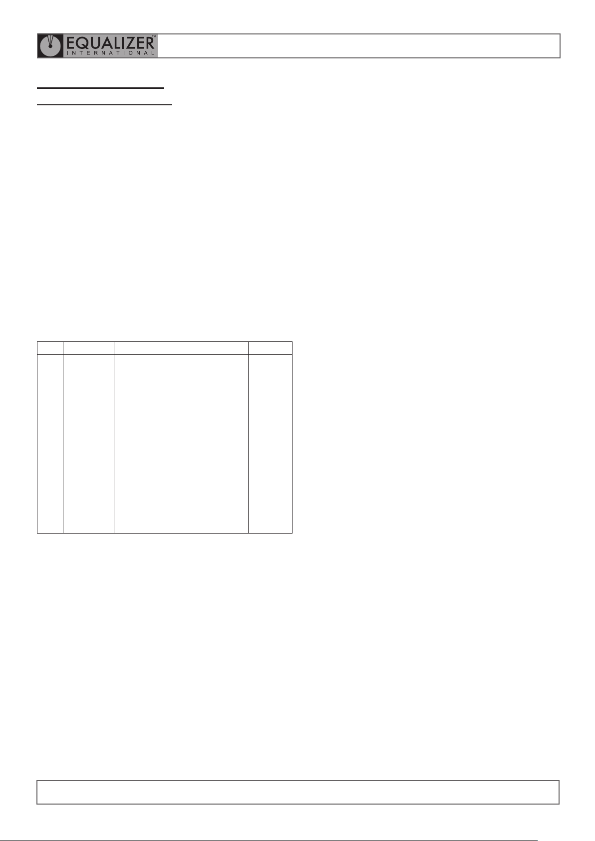
ITEM PART NO. DESCRIPTION Q T Y.
01
02
03
04
301301-01
05
313401-01
06
313501-01
07
403102-01
08
632001-01
09
740101-01
10
740201-01
11
740301-01
12
740401-01
13
740501-01
14
740601-01
15
740701-01
16
740901-01
17
741101-01
18
740801-01
19
742001-01
20
742101-01
21
743101-01
22
373401-01
23
306502-01
READ INST. STICKER
QC SEALED STICKER
MG7TM WRAP STICKER
M6X12 GRUB SCREW
THRUST WASHER
THRUST RACE
SPLIT RING 1 1/4” 32mm
M8 SPRING PLUNGER
CAST LEG LEFT HAND
CAST LEG RIGHT HAND
MAIN BODY
SPLITTER WEDGE
LARGE SPREADING BAR
SMALL SPREADING BAR
DRIVE SCREW
OUTER SLEEVE
8 MM PLUNGER
HANDLE PLUG
BEARING WASHER
7 MM PLUNGER
COILED SPRING PIN
HANDLE ROD
HANDLE GRIP
01 each
01 each
01 each
01 each
01 set of 2
01 each
02 each
01 set of 2
01 each
01 each
01 each
01 each
01 each
01 each
01 each
01 each
01 each
01 each
01 each
01 set of 2
01 each
01 each
01 each
MG7TM
18
MINI GAP FLANGE SPREADER
Page 20
EQUALIZER INTERNATIONAL LTD.
Head Office
Equalizer House
Claymore Drive
Aberdeen
Scotland
UK
AB23 8GD
t: +44 (0) 1224 701970
f: +44 (0) 1224 823791
www.equalizerinternational.com
 Loading...