

Page 1
HP350S, HP350D,
HP550S, HP550D
HP1000S, HP1000D
HYDRAULIC SEALED
HAND PUMPS
Operator Instruction Manual
www.equalizerinternational.com
INNOVATION IN ITS MOST FUNCTIONAL FORM
Page 2

Page 3

INDEX
SECTION CONTENTS PAGE NO.
1 INTRODUCTION 1
2 SAFETY INFORMATION 2-3
3 KIT COMPONENTS 4
4 TECHNICAL DATA 5
5 HOW THE HAND PUMPS WORK 6
6 INSTALLATION AND OPERATION 7-12
6.1 HP350S, HP550S & HP1000S
6.2 HP350D, HP550D & HP1000D
7-8
9-12
7 EXAMINATION, MAINTENANCE AND STORAGE 13
8 PARTS LISTS 14-16
9 WEIGHTS AND DIMENSIONS 17
10 TROUBLESHOOTING 18-19
1. INTRODUCTION
The Equalizer HP-S hydraulic single-port sealed hand pump and HP-D hydraulic twin-port
sealed hand pump replace the Equalizer P142 hydraulic hand pump.
The HP350S, HP550S, HP1000S, HP350D and HP550D and HP1000D are tailored for use
with Equalizer International Ltd hydraulic equipment. Their output is regulated to 700bar
(10,000psi) and is delivered from an output port threaded ⅜” NPT. The HP350S and HP350D
can be used with any 700 bar (10,000 psi) rated hydraulic equipment with an oil capacity of 350cc (21.35 in3) or less. The HP550S and HP550D can be used with any 700bar
(10,000psi) rated hydraulic equipment with an oil capacity of 550cc (30.51 in3) or less. The
HP1000S and HP1000D can be used with any 700bar (10,000psi) rated hydraulic equipment
with an oil capacity of 1000cc (61.0 in3) or less.
The diaphragm oil reservoir means that, unlike conventional hand pump units, the HP-S and
HP-D pump ranges are operable at all angles and are highly resistant to accidental spillage of
hydraulic uid.
Pressure rating:
● 1st stage: 13.8 bar (197 psi)
● 2nd stage: 700 bar (10,000 psi)
HYDRAULIC SEALED HAND PUMPS
OPERATOR INSTRUCTION MANUAL
HP IM REV 07
06/06/2014
PAGE 1
Page 4

2. SAFETY INFORMATION
The operator MUST read this manual prior to using the tools.
Failure to comply with the following cautions and warnings could cause equipment
damage and personal injury; read the manual fully!
Read all the following instructions, warnings and cautions carefully. Follow all safety
precautions to avoid personal injury or property damage during system operation.
Equalizer International Ltd cannot be responsible for damage or injury resulting from unsafe
product use, lack of maintenance or incorrect product and/or system operation. Contact
Equalizer International Ltd when in doubt as to the safety precautions and applications. To
protect your warranty, use only good quality hydraulic oil of the grade 15cSt.
Only people competent in the use of hydraulic equipment should use these tools.
In all installations the site safety requirements must be adhered to. ALSO the safety of the
operator, and when present, any assisting personnel, is of paramount importance along with
the safety of others including, when present, the general public.
These instructions are only to cover the safe operation of THE EQUALIZER HP350S, HP550S,
HP1000S, HP350D, HP550D and HP1000D HYDRAULIC SEALED HAND PUMPS during normal
maintenance/installation operations. All other safety aspects must be controlled by the
operation supervisor.
HYDRAULIC SEALED HAND PUMPS
OPERATOR INSTRUCTION MANUAL
PAGE 2
Page 5

A CAUTION is used to indicate correct operating or maintenance procedures and practices to
prevent damage to, or destruction of equipment or other property.
A WARNING indicates a potential danger that requires correct procedures or practices to avoid
personal injury.
A DANGER is only used when your action or lack of action may cause serious injury or even
death.
IMPORTANT: Operator must be competent in
the use of hydraulic equipment. The operator
must have read and understood all instructions,
safety issues, cautions and warnings before
starting to operate the Equalizer equipment.
WARNING: To avoid personal injury and
possible equipment damage, make sure all
hydraulic components are rated to a safe
working pressure of 700 bar (10,000 psi)
WARNING: Do not overload equipment. Overloading causes equipment failure and possible
personal injury.
CAUTION: Make sure that all system components are protected from external sources of
damage, such as excessive heat, ame, moving machine parts, sharp edges and corrosive
chemicals.
CAUTION: Avoid sharp bends and kinks that
will cause severe back-up pressure in hoses.
Bends and kinks lead to premature hose failure.
Do not drop heavy objects onto hoses. A sharp
impact may cause internal damage to hose wire
strands; applying pressure to a damaged hose
may cause it to rupture. Do not place heavy
weights on the hoses, or allow vehicles to roll
over the hoses; crush damage will lead to premature hose failure.
WARNING: Immediately replace worn
or damaged parts with genuine Equalizer
parts. Equalizer parts are designed to t
properly and withstand rated loads. For
repair or maintenance service contact your
Equalizer distributor or service centre.
DANGER: To avoid personal injury keep
hands and feet away from the tool and
workpiece during operation.
WARNING: Always wear suitable clothing
and Personal Protective Equipment (PPE).
DANGER: Do not handle pressurised hoses. Escaping oil under pressure can penetrate the skin, causing serious injury. If
oil is injected under the skin, seek medical
attention immediately.
WARNING: Never pressurize unconnected
couplers. Only use hydraulic equipment in
a connected system.
IMPORTANT: Do not lift hydraulic equipment by the hoses or couplers. Use the carrying handle or other means of safe transport.
CAUTION: Do not operate the equipment
without lubricating all moving parts. Use
only high pressure molybdenum disulphide
grease.
HYDRAULIC SEALED HAND PUMPS
OPERATOR INSTRUCTION MANUAL
PAGE 3
Page 6
3. KIT COMPONENTS
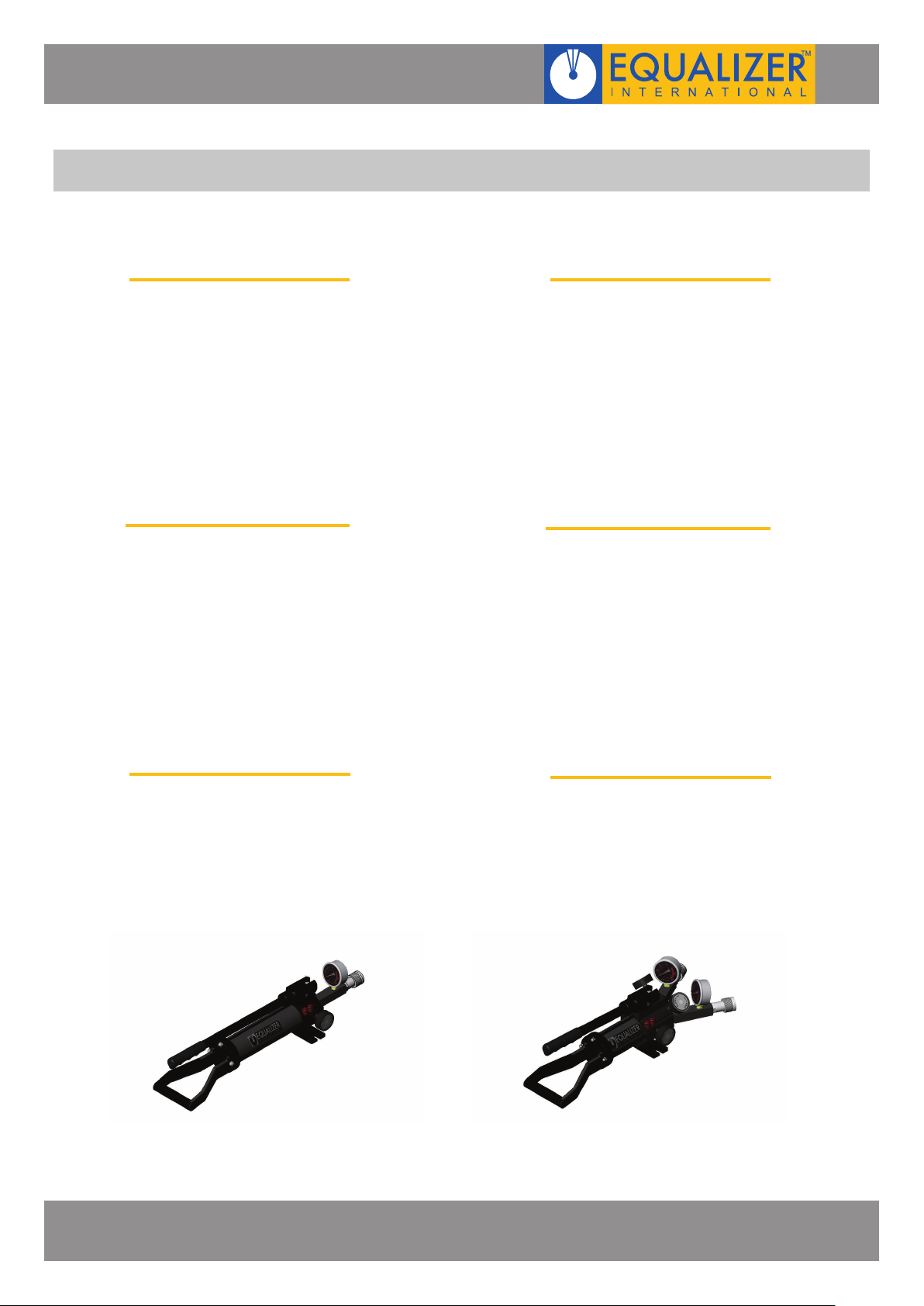
HP350S KIT COMPONENTS
1 x HP350S Pump Unit
1 x Pressure Gauge
1 x ⅜” Port Gauge Adaptor
1 x Instruction Manual
1 x Cardboard Packaging
Product Code: HP350SMIN
HP550S KIT COMPONENTS
1 x HP550S Pump Unit
1 x Pressure Gauge
1 x ⅜” Port Gauge Adaptor
1 x Instruction Manual
1 x Cardboard Packaging
Product Code: HP550SMIN
HP350D KIT COMPONENTS
1 x HP350D Pump Unit
2 x Pressure Gauge
2 x ⅜” Port Gauge Adaptor
1 x Instruction Manual
1 x Cardboard Packaging
Product Code: HP350DMIN
HP550D KIT COMPONENTS
1 x HP550D Pump Unit
2 x Pressure Gauge
2 x ⅜” Port Gauge Adaptor
1 x Instruction Manual
1 x Cardboard Packaging
Product Code: HP550DMIN
HP1000S KIT COMPONENTS
1 x HP1000S Pump Unit
1 x Pressure Gauge
1 x ⅜” Port Gauge Adaptor
1 x Instruction Manual
1 x Cardboard Packaging
Product Code: HP1000SMIN
HP1000D KIT COMPONENTS
1 x HP1000D Pump Unit
2 x Pressure Gauge
2 x ⅜” Port Gauge Adaptor
1 x Instruction Manual
1 x Cardboard Packaging
Product Code: HP1000DMIN
HYDRAULIC SEALED HAND PUMPS
OPERATOR INSTRUCTION MANUAL
PAGE 4
Page 7

4. TECHNICAL DATA
STAGE HP350S HP550S HP1000S
PUMP TYPE TWO SPEED TWO SPEED TWO SPEED
PRESSURE RATING 1st 13.8bar (197psi) 13.8bar (197psi) 13.8bar (197psi)
2nd 700bar (10,000psi) 700bar (10,000psi) 700bar (10,000psi)
NOMINAL OIL CAPACITY 350cc (21.4in3) 550cc (33.6in3) 1000cc (61.0in3)
USABLE OIL CAPACITY 300.0cc (18.3in3) 580.0cc (35.4in3) 1110.0cc (67.7in3)
OIL VOLUME PER
STROKE
MAX HANDLE EFFORT 33kgf (72.75lbf) 25kgf (55.12lbf) 21kgf (46.30lbf)
PISTON STROKE 18.0mm (0.71”) 18.0mm (0.71”) 18.0mm (0.71”)
HYDRAULIC OIL Grade 15 cSt Grade 15 cSt Grade 15 cSt
1st 3.62cc (0.221in3) 3.62cc (0.221in3) 3.62cc (0.221in3)
2nd 0.77cc (0.046in3) 0.77cc (0.046in3) 0.77cc (0.046in3)
STAGE HP350D HP550D HP1000D
PUMP TYPE TWO SPEED TWO SPEED TWO SPEED
PRESSURE RATING 1st 13.8bar (197psi) 13.8bar (197psi) 13.8bar (197psi)
2nd 700bar (10,000psi) 700bar (10,000psi) 700bar (10,000psi)
NOMINAL OIL CAPACITY 350cc (21.4in3) 550cc (33.6in3) 1000cc (61.0in3)
USABLE OIL CAPACITY 300.0cc (18.3in3) 580.0cc (35.4in3) 1110.0cc (67.7in3)
OIL VOLUME PER
STROKE
MAX HANDLE EFFORT 33kgf (72.75lbf) 25kgf (55.12lbf) 21kgf (46.30lbf)
PISTON STROKE 18.0mm (0.71”) 18.0mm (0.71”) 18.0mm (0.71”)
HYDRAULIC OIL Grade 15 cSt Grade 15 cSt Grade 15 cSt
1st 3.62cc (0.221in3) 3.62cc (0.221in3) 3.62cc (0.221in3)
2nd 0.77cc (0.046in3) 0.77cc (0.046in3) 0.77cc (0.046in3)
HYDRAULIC SEALED HAND PUMPS
OPERATOR INSTRUCTION MANUAL
PAGE 5
Page 8
5. HOW THE HAND PUMPS WORK
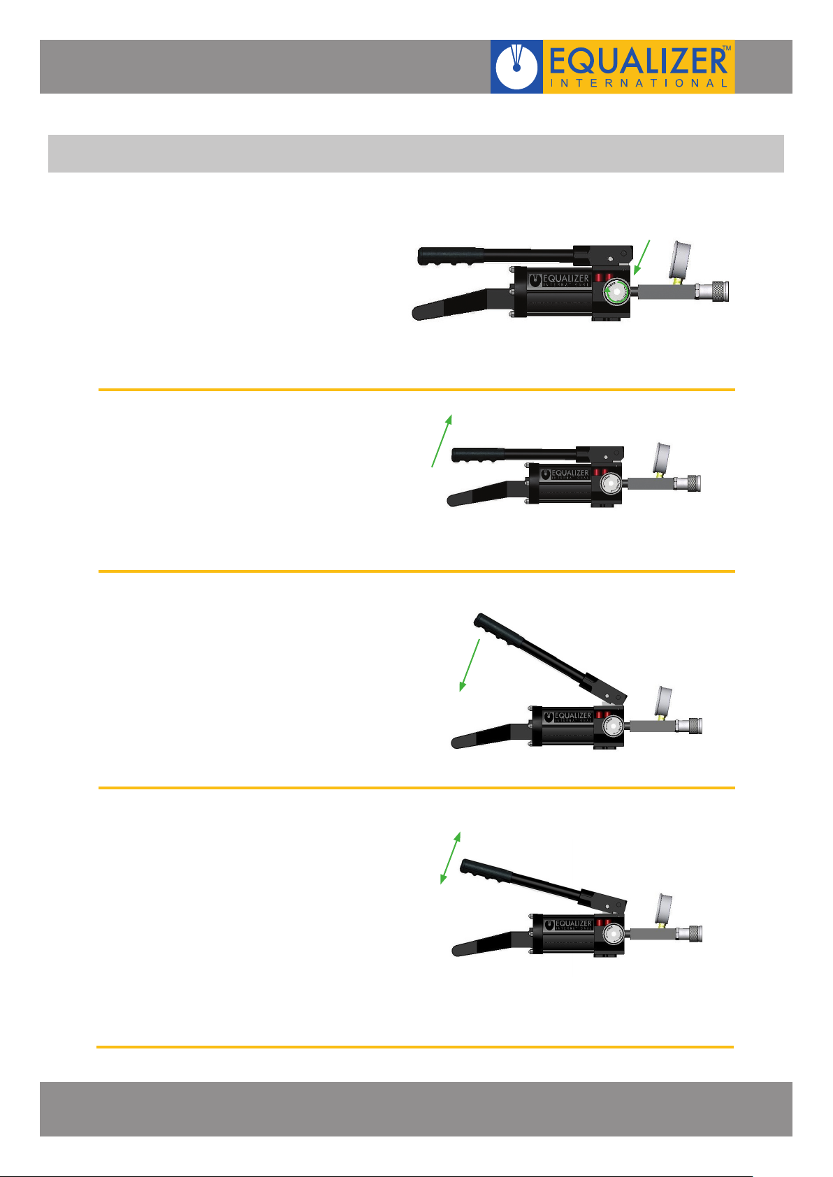
1. The release valve is closed fully by
rotating clockwise until hand tight
2. The pump handle is raised, which
creates a vacuum in the piston
chamber which sucks oil from the
reservoir into the chamber
CLOSE RELEASE
VALVE
3. The pump handle is depressed,
which pumps the oil from the
chamber through the outlet port
and into the system to which the
pump is connected
4. Steps 2 & 3 are repeated, which will
pump oil into the system until the
maximum pressure of
10,000 psi (700 bar) is achieved, at
which point the safety release valve
will open and the oil will cycle back
to the reservoir
HYDRAULIC SEALED HAND PUMPS
OPERATOR INSTRUCTION MANUAL
PAGE 6
Page 9
6. INSTALLATION AND OPERATION
6.1 HP350S, HP550S & HP1000S
WARNING:
Never attempt to pressurise the pump when the pressure gauge is not
connected or the pump is not connected to a system!
DANGER:
Always check the hydraulic system in which the pump is to be used is rated
for 10,000 psi (700 bar). Over pressurising a hydraulic system will result in
component failure and personal injury!
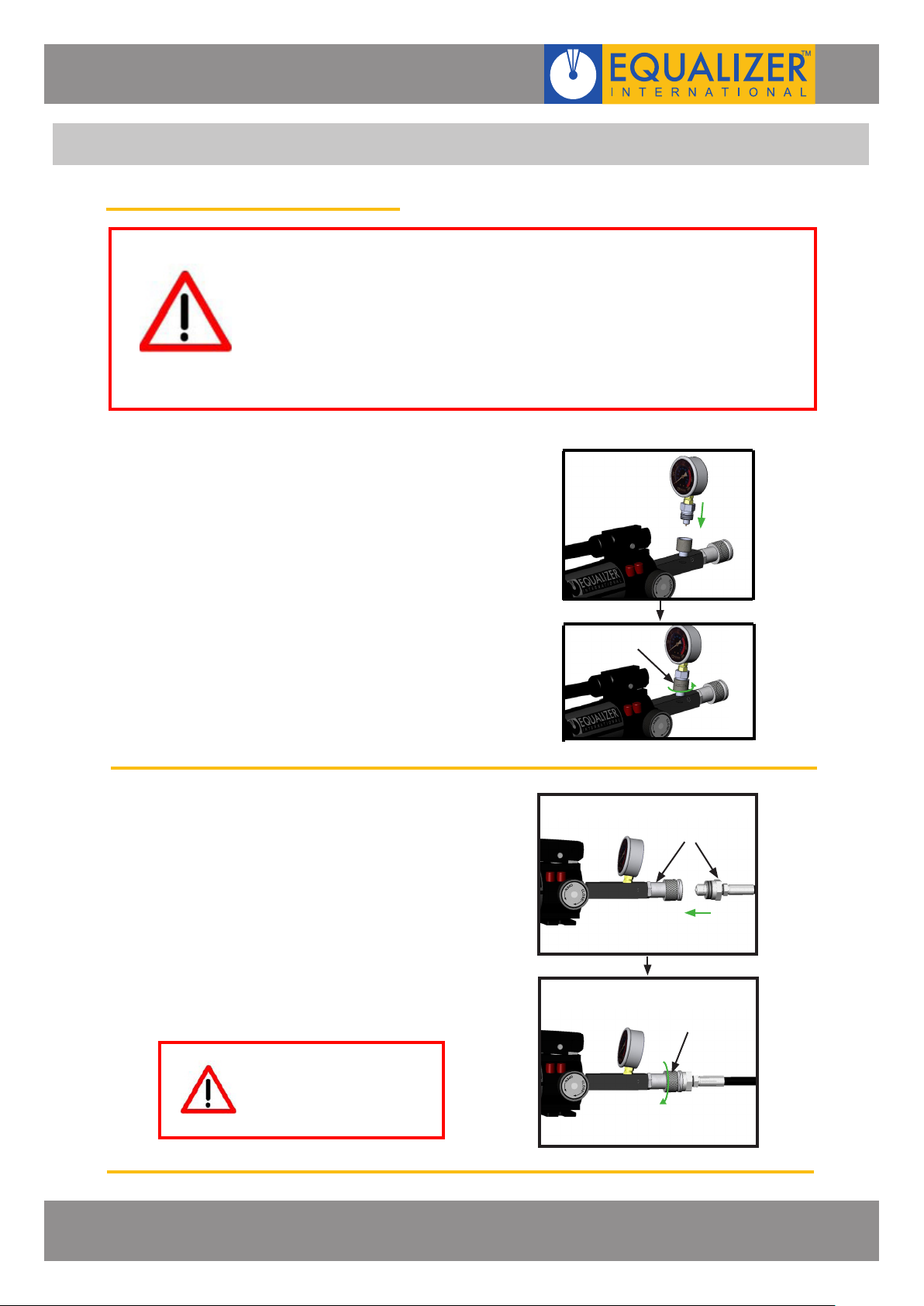
1. Prior to using the pump the hydraulic
gauge must be tted.
push the male connector on the gauge
and female connector on the gauge
adaptor together fully and rotate the
locking ring counterclockwise until fully
tight.
LOCKING
RING
2. Ensure the hydraulic system you
wish to pressurise has been bled
and is free from air and leaks.
Connect the pump into the system
using the screw connector supplied
with the pump, push the male and
female connectors together fully and
rotate the locking ring clockwise
until fully tight.
WARNING:
Never disconnect the pump
or other components when
the system is pressurised
HYDRAULIC SEALED HAND PUMPS
OPERATOR INSTRUCTION MANUAL
MALE AND FEMALE
CONNECTORS
LOCKING
RING
PAGE 7
Page 10
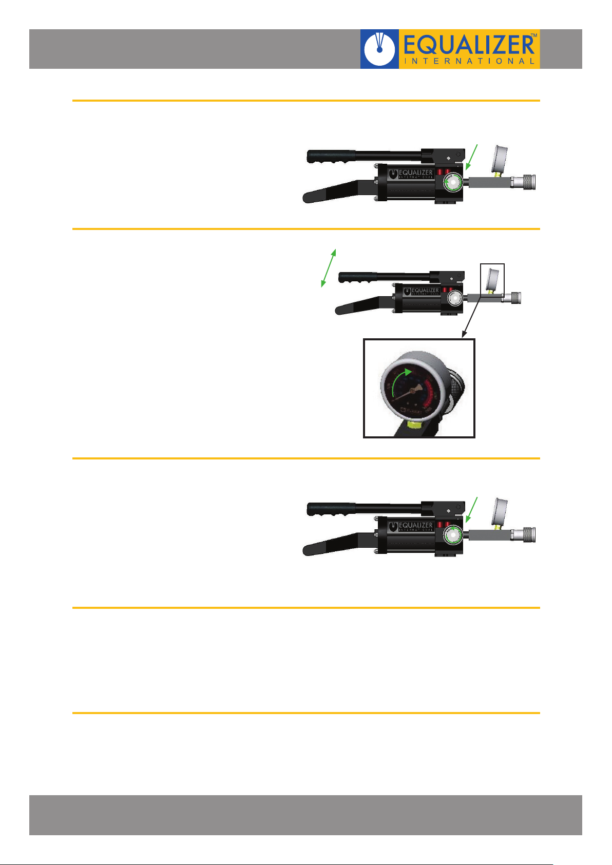
3. Close the release valve fully by
rotating clockwise until hand tight
4. Pressurise the system by raising and
depressing the pump handle until
the desired pressure is indicated
on the pressure gauge
N.B. max. pressure 10,000 psi (700
bar)
CLOSE RELEASE
VALVE
5. To depressurise the system, gently
open the release valve by rotating
the release knob anti-clockwise
6. Once the system has been fully
depressurised, the pump can be
disconnected by unscrewing the
connectors.
OPEN RELEASE
VALVE
HYDRAULIC SEALED HAND PUMPS
OPERATOR INSTRUCTION MANUAL
PAGE 8
Page 11
6.2 HP350D, HP550D & HP1000D
The HP350D, HP550D and HP1000D pumps have been designed for use with Equalizer maxi kit
systems, however the HP350D can be used in any situation where 2 separate hydraulic systems
require to be pressurised and controlled independently by the same operator.
WARNING:
Never attempt to pressurise the pump when the gauge is not connected or
the pump is not connected to a system!
DANGER:
Always check the hydraulic system in which the pump is to be used is rated
for 10,000 psi (700 bar). Over pressurising a hydraulic system will result in
component failure and personal injury!
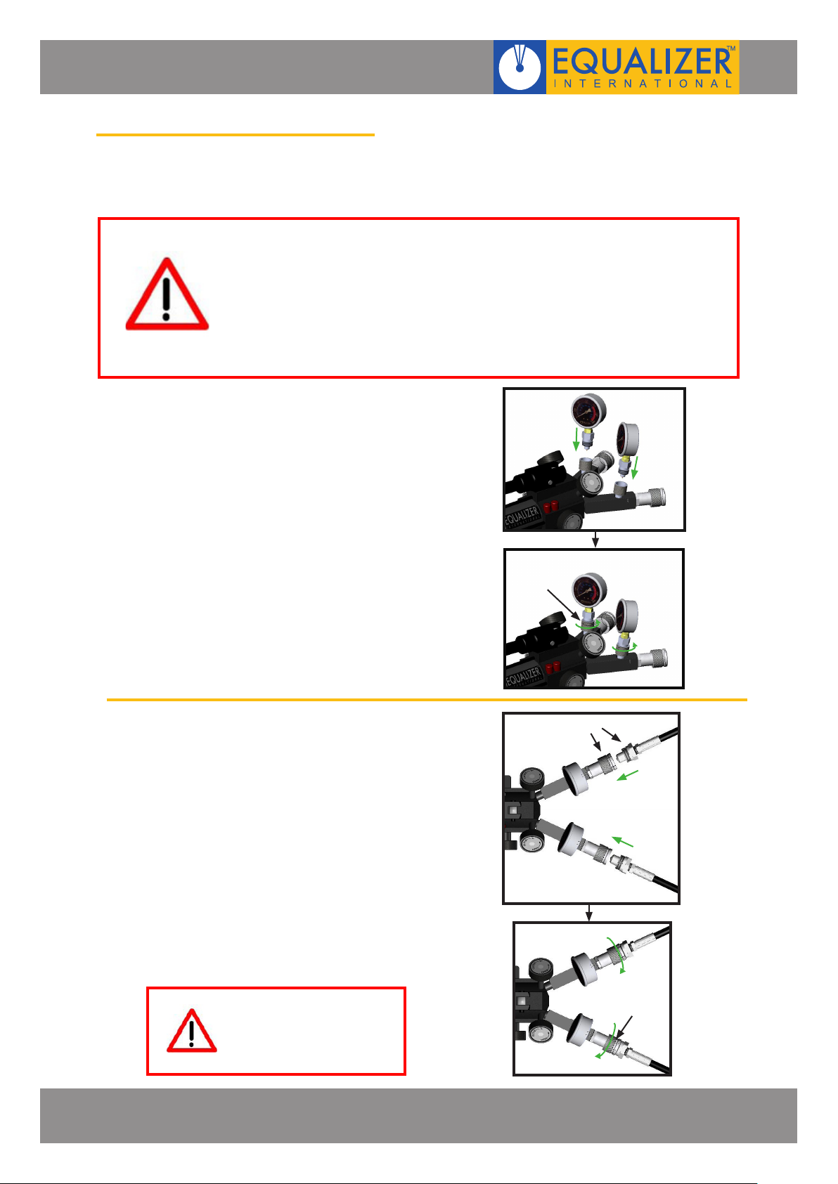
1. Prior to using the pump the hydraulic
gauges must be tted.
push the male connector on the gauges
and female connector on the gauge
adaptors together fully and rotate the
locking ring counterclockwise until fully
tight.
2. Ensure the hydraulic systems you
wish to pressurise have been bled
and are free from air and leaks.
Connect the pump into the systems
using the screw connectors supplied
with the pump, push the male and
female connectors together fully and
rotate the locking rings clockwise
until fully tight.
LOCKING
RING
MALE AND FEMALE
CONNECTORS
WARNING:
Never disconnect the pump
or other components when
the system is pressurised
HYDRAULIC SEALED HAND PUMPS
OPERATOR INSTRUCTION MANUAL
LOCKING
RING
PAGE 9
Page 12
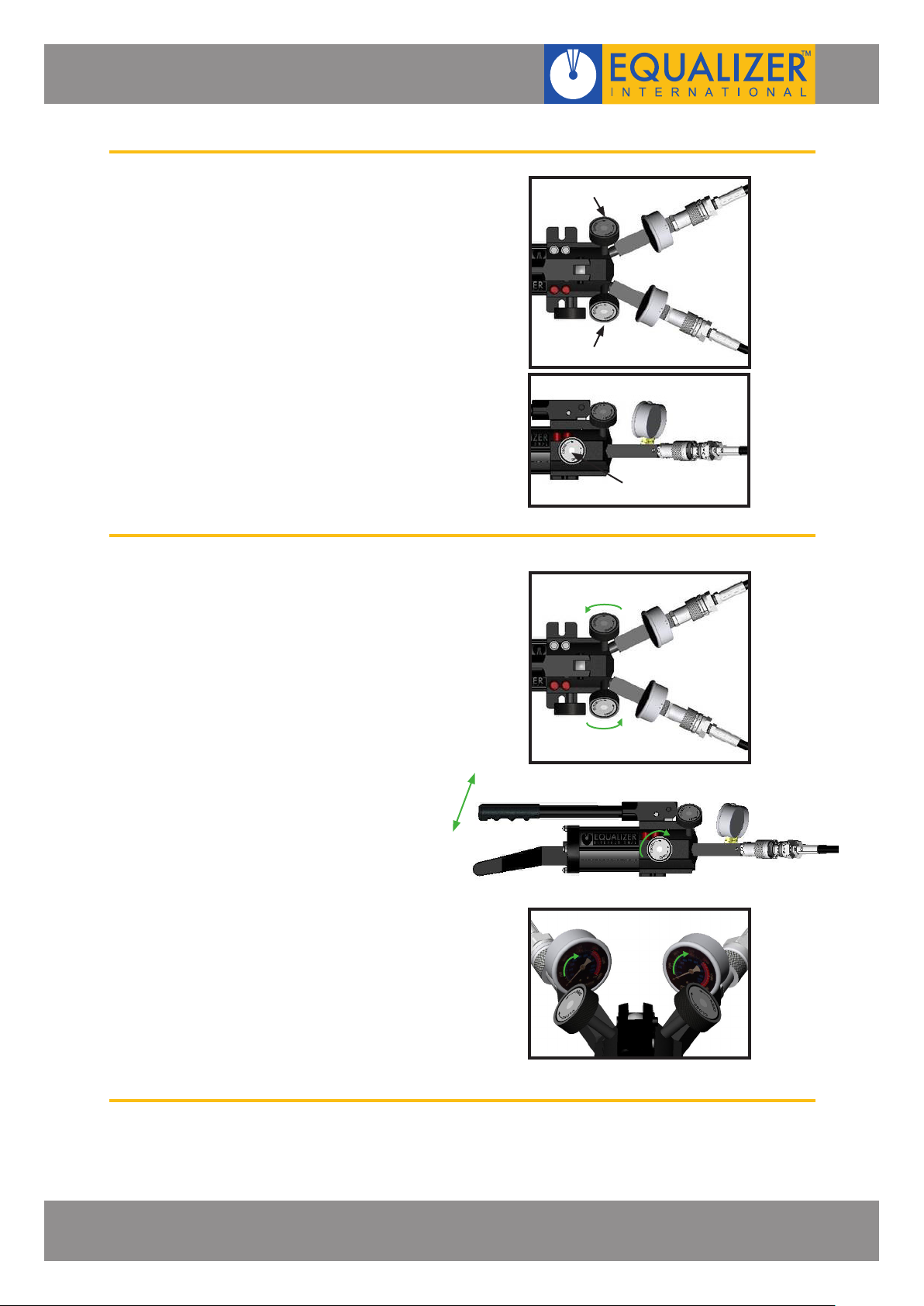
3. The HP-S pumps are tted with two
control valves and a release valve.
This enables the operator to adjust
the pressure on both hydraulic
systems independently or
simultaneously.
a.
If control valves 1 and 2 are set to
the fully open position and the
release valve is screwed fully home,
when the pump handle is raised and
lowered both hydraulic systems will
be pressurised to an equal pressure
(max. pressure 10,000 psi (700
bar))
CONTROL VALVE 1
CONTROL VALVE 2
RELEASE VALVE
HYDRAULIC SEALED HAND PUMPS
OPERATOR INSTRUCTION MANUAL
PAGE 10
Page 13
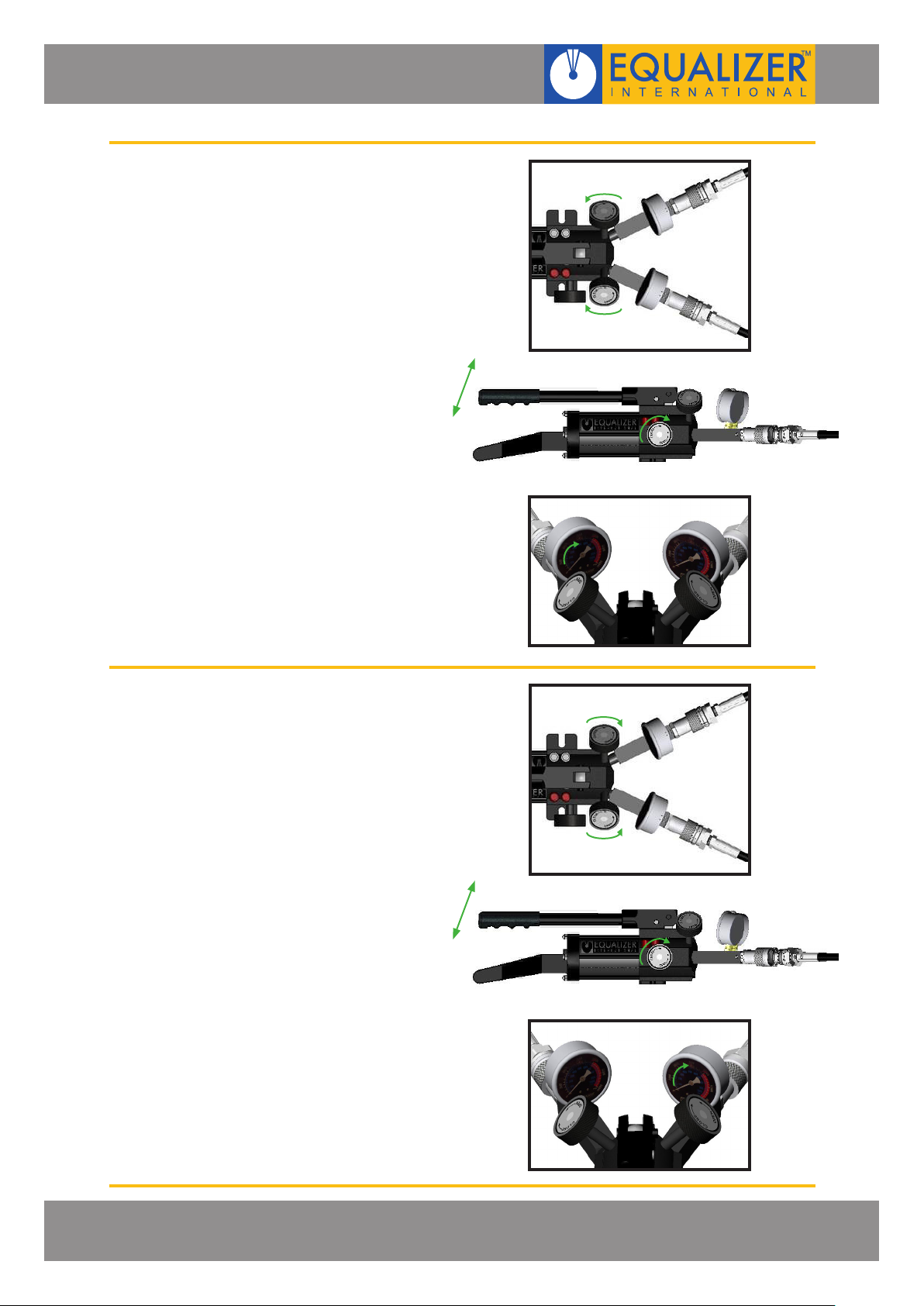
b.
If control valve 1 is open and
control valve 2 is closed with the
release valve screwed fully home,
when the pump handle is raised and
lowered only the system connected
to control valve 1 will be pressurised
(max. pressure 10,000 psi (700
bar))
c.
If control valve 2 is open and
control valve 1 is closed with the
release valve screwed fully home,
when the pump handle is raised and
lowered only the system connected
to control valve 2 will be pressurised
(max. pressure 10,000 psi (700
bar))
HYDRAULIC SEALED HAND PUMPS
OPERATOR INSTRUCTION MANUAL
PAGE 11
Page 14
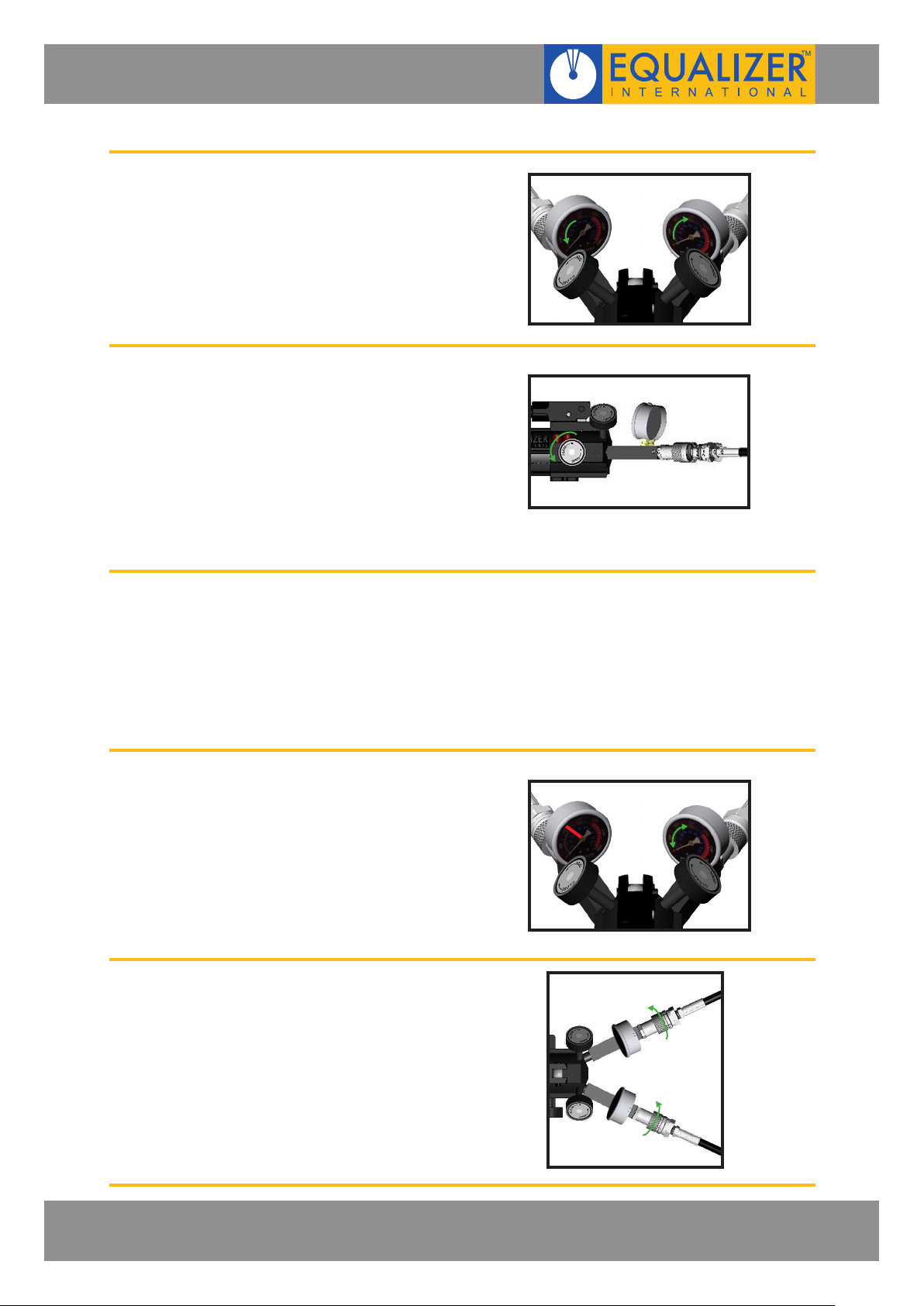
d.
If after pressurising one system the
control valve for the unpressurised
system is opened then the pressure
in both systems will adjust until they
are equal
4.
a.
To depressurise both systems
simultaneously open both control
valves and gently open the release
valve by rotating the release knob
anti-clockwise
b.
To depressurise only one system
open only the control valve for that
system and gently open the release
valve by rotating the release knob
anti-clockwise
5. At any time during pressurisation
of the systems the appropriate
control can be closed to hold one
system at a xed pressure while the
pressure in the other system can be
increased by raising and lowering
the pump handle or decreased by
opening the release valve
6. Once both systems have been fully
depressurised the pump can be
disconnected by unscrewing the
couplers
HYDRAULIC SEALED HAND PUMPS
OPERATOR INSTRUCTION MANUAL
PAGE 12
Page 15

7. EXAMINATION, MAINTENANCE AND STORAGE
• On return from each job and before allocation against subsequent work the
hand pumps should be examined to ensure that they are serviceable.
• Any missing or damaged items are to be replaced as soon as possible and prior to the
pump being used again.
• Store the pump in a cool dry place and ensure all machined surfaces are greased.
• Grease all moving parts each and every time the pump is used.
HYDRAULIC SEALED HAND PUMPS
OPERATOR INSTRUCTION MANUAL
PAGE 13
Page 16
n
DESCRIPTION
PUMP HOUSING
SERVICE KIT A:
- OIL FILTER
- O-RING
- RESERVOIR BLADDER
- REFILLING PLUG
RESERVOIR
SERVICE KIT B:
- TAIL BASE
- SCREW
- SPRING WASHER
SERVICE KIT C:
- O-RING
- BACK-UP RING
- PUMP PISTON
- SNAP RING
- O-RING
- BACK-UP RING
- PUMP PISTON
SERVICE KIT D:
- HANDLE
- YOKE
- PISTON PIN
- YOKE PIN
- RETAINING RING
SERVICE KIT E:
- YOKE BASE
- SPRING PIN
SERVICE KIT F:
- RELEASE VALVE
SCREW
- WASHER
- SEAL
- SCREW
- RELEASE KNOB
- COUPLERS
- CHECK BALL
SERVICE KIT G:
- SPRING
- STEEL BALL
- OUTLET BALL SPRING
- COPPER WASHER
- VALVE COVER SCREW
- STEEL BALL
PART No.
710101-01
715100-01
710601-01
725200-01
715300-01
715400-01
715500-01
715600-01
715700-01
KIT
QUANTITY
01
01
01
01
01
04
04
01
01
01
01
01
01
01
01
01
01
01
01
01
01
01
01
01
01
01
01
01
02
02
02
02
02
02
ITEM
01
02
03
04
05
06
07
08
09
11
12
13
14
15
16
17
18
19
20
21
22
25
26
27
28
29
30
31
32
33
34
35
36
37
38
39
DESCRIPTION
SERVICE KIT H:
- STEEL BALL
- SPRING END CAP
- L.P. SPRING
- O-RING
- OVERLOAD COVER
SCREW
- CAP
- OVERLOAD COVER
SCREW
SERVICE KIT I:
- BASE PLATE
- SCREW
PART No.
715800-01
715900-01
KIT
QUANTITY
01
01
01
02
01
02
01
01
02
ITEM
40
41
42
43
44
45
46
50
51
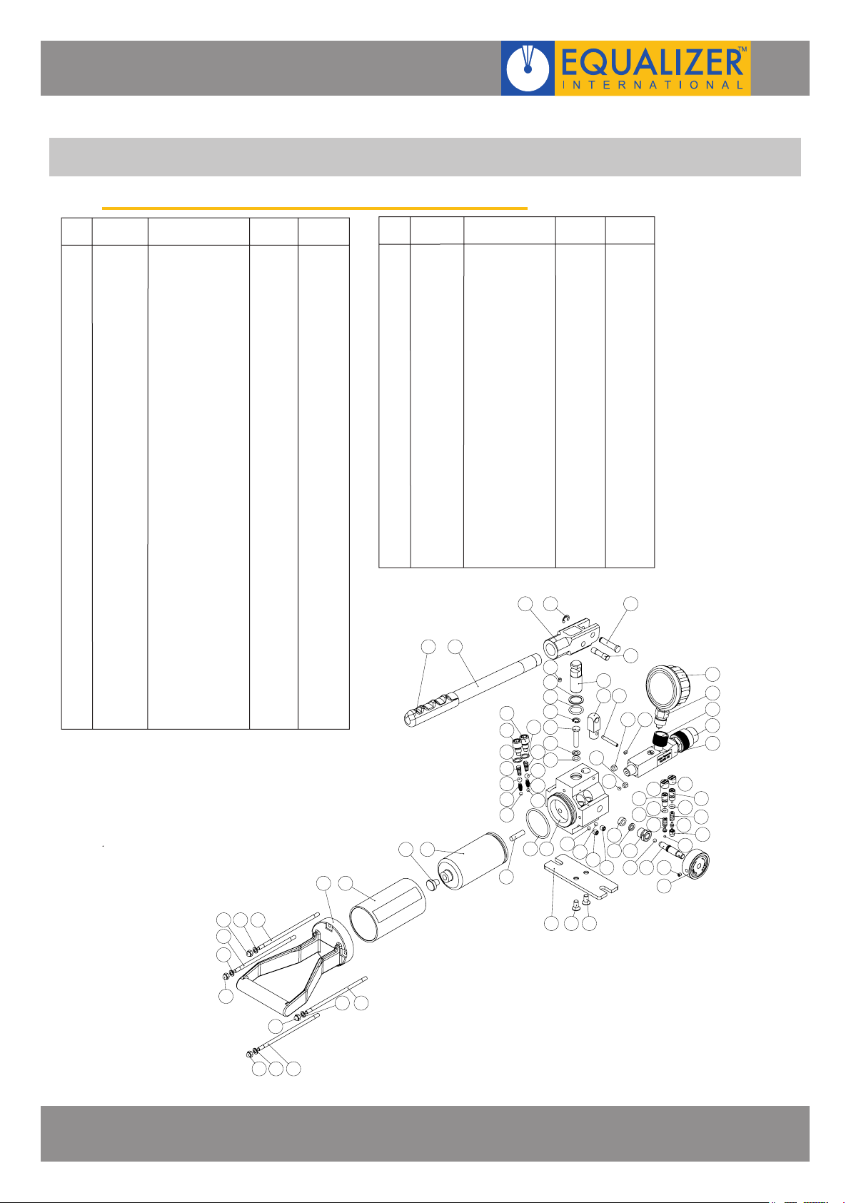
8. PARTS LISTS
HP350S HYDRAULIC SINGLE-PORT SEALED HAND PUMP
- NUT
- HANDLE GRIP
- SCREW
0410
0123
0124
PUMP
QUANTITY
01
01
01
01
01
01
01
04
04
04
01
01
01
01
01
01
01
01
01
01
01
01
01
01
01
01
01
01
01
01
01
01
01
02
02
02
02
02
02
76
52
53
24
33
54
55
56
57
58
54
716100-01
716200-01
716300-01
23 18
- CONE SEAT0 147
- CONE 0148
- LONG SEPARATOR
SPRING
SERVICE KIT K:
- SCREW
- SCREW
- SCREW
- CHECK BALL
SERVICE KIT L:
- GAUGE COUPLER
MALE
- GAUGE
SERVICE KIT M:
- GAUGE COUPLER
FEMALE
- COUPLER
- GAUGE PORT
ADAPTOR
38
373836
36
35
34
39
2
PUMP
QUANTITY
0149
04
01
01
04
01
01
01
01
01
19 22 21
24
16
15
14
37
13
12
11
35
34
39
3
1
17
25 26
52
33
33
29
28 32
33
52
52
01
01
01
02
01
02
01
01
01
01
01
02
03
01
01
03
01
01
01
01
01
20
53 24
44
42
33 273130
55
54
56
57
58
45
45
43
41
46
43
49
48
47
40
8910
8
9
10
HYDRAULIC SEALED HAND PUMPS
OPERATOR INSTRUCTION MANUAL
50 51 51
89
10
8910
PAGE 14
Page 17
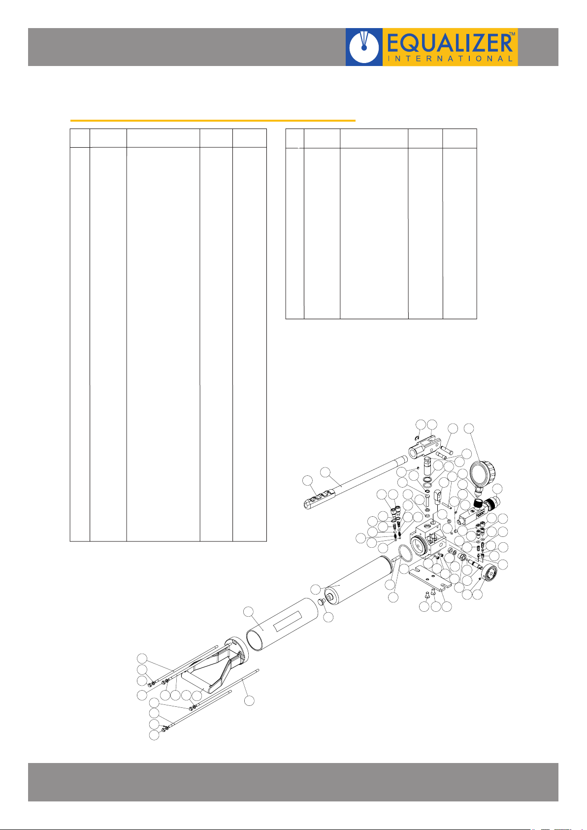
HP550S HYDRAULIC SINGLE-PORT SEALED HAND PUMP
ITEM
01
02
03
04
05
06
07
08
09
10
11
12
13
14
15
16
17
37
18
19
20
21
22
23
24
25
26
27
28
29
30
31
32
33
34
35
36
37
38
54
39
40
PART No.
710101-01
730601-01
715300-01
715500-01
715600-01
715700-01
715800-01
715900-01
716100-01
716200-01
DESCRIPTION
PUMP HOUSING
RESERVOIR
SERVICE KIT C:
- O-RING
- BACK-UP RING
- H.P. PISTON
- SNAP RING
- O-RING
- BACK-UP RING
- L.P. PISTON
SERVICE KIT E:
- YOKE BASE
- SPRING PIN
SERVICE KIT F:
- SEAL
- WASHER
- RELEASE VALVE
SCREW
- SCREW
- RELEASE KNOB
- COUPLERS
- CHECK BALL
SERVICE KIT G:
- SPRING
- STEEL BALL
- OUTLET BALL SPRING
- COPPER WASHER
- VALVE COVER SCREW
- STEEL BALL
SERVICE KIT H:
- STEEL BALL
- SPRING END CAP
- L.P. SPRING
- O-RING
- OVERLOAD COVER
SCREW
- CAP
- CONE SEAT
- CONE
- LONG SEPARATOR
SPRING
- OVERLOAD COVER
SCREW
SERVICE KIT I:
- BASE PLATE
- SCREW
SERVICE KIT K:
- SCREW
- CHECK BALL
- SCREW
- SCREW
SERVICE KIT L:
- GAUGE COUPLER
MALE
- GAUGE
KIT
QUANTITY
01
01
01
01
01
01
01
01
01
01
01
01
01
01
01
01
02
02
02
02
02
02
01
01
01
02
01
02
01
01
01
01
01
02
04
04
01
01
01
01
PUMP
QUANTITY
01
01
01
01
01
01
01
01
01
01
01
01
01
01
01
01
01
01
02
02
02
02
02
02
01
01
01
02
01
02
01
01
01
01
01
02
03
03
01
01
01
01
2
ITEM
41
42
43
44
45
46
47
48
49
50
51
52
53
55
56
57
58
4
PART No.
716300-01
735100-01
735300-01
735200-01
53
44
DESCRIPTION
SERVICE KIT M:
- GAUGE COUPLER
FEMALE
- COUPLER
- PORT GAUGE
ADAPTOR
SERVICE KIT N:
- RESERVOIR BLADDER
- OIL FILTER
- O-RING
- REFILLING PLUG
SERVICE KIT O:
- HANDLE
- YOKE
- PISTON PIN
- YOKE PIN
- RETAINING RING
- HANDLE GRIP
- SCREW 0154
SERVICE KIT P:
- SCREW
- TAIL BASE
- SPRING WASHER
- NUT
48
47
KIT
QUANTITY
54
6
5
3
2222
20
21
21
19
18
23
19
20
23
1
45
46
PUMP
QUANTITY
01
01
01
01
01
01
01
01
01
01
01
01
01
04
01
04
04
4
18
37
01
01
01
01
01
01
01
01
01
01
01
01
01
01
04
01
04
04
4952
36
40
51
50
9
8
7
39
11
10
41
54
36
43
38
37
29
27
12
13
37
37
36
14
17
15 16
343535
42
29
33
28
3227
31
2526
30
24
55
57
58
58 57 555657
58
55
57
58
HYDRAULIC SEALED HAND PUMPS
OPERATOR INSTRUCTION MANUAL
55
PAGE 15
Page 18
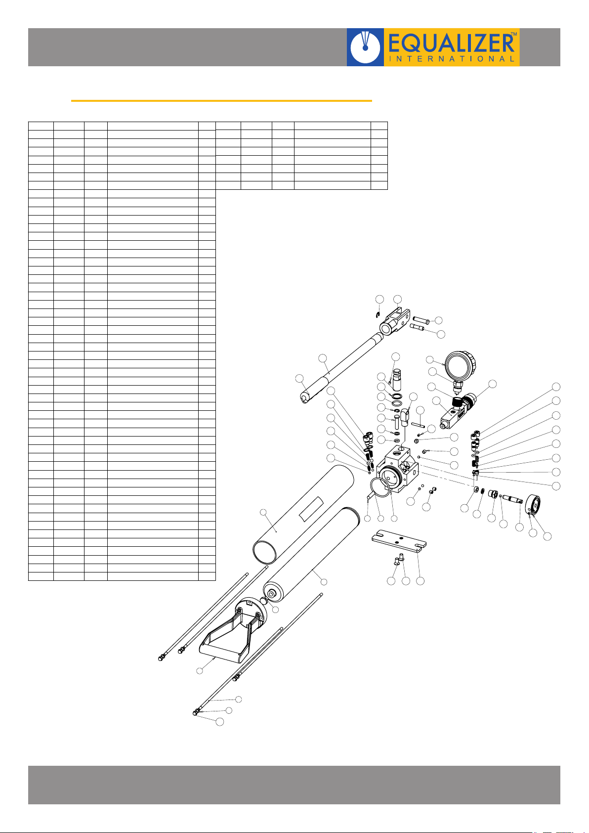
HP1000S HYDRAULIC SINGLE-PORT SEALED HAND PUMP
ITEM NO.
PART NO
1 710101-01
2 710201-01
3 707003-01
4 520001-01
5 710501-01
6 520002-01
7 710701-01
8 520003-01
9 707009-01
10 710901-01
11 712801-01
12 713201-03
13 707013-01
14 711001-01
15 711101-01
16 711201-01
17 711301-01
18 711401-01
19 711501-01
20 711601-01
21 712201-01 E
22 712301-01 E
23 712001-01
24 711701-01
25 711801-01
26 711901-01
27 708004-01
28 201202-01
29 707029-01 G/Q
30 713501-02 G
31 713601-02 G
32 713701-02 G
33 713801-02 G
34 713901-02 GV ALVLE COVER SCREW 2
35 714001-02
36 714101-02
37 714201-01
38 714401-02
39 714501-02
40 714601-02
41 377201-01
42 377301-01
43 377401-01
44 707044-01
45 707067-01
46 707072-01
47 714901-01
48 715001-01
49 771110-01
50 707072-01
51 302501-01
52 070054-01
53 300401-01
KIT
-
A/N
A/N
T
A/N
-
B/P
U
B/P
B/P NUT
F/K/R
K
D/K/O
C
C
C
C
C
C
C
D/O
D/O
D/O
D/O
O HANDLE
D/O
H
H
H
H
H
H
H
H
H
H
Q
M
I
I
M
L
L
-
F/J
DESCRIPTION
PUMP HOUSING
OIL FILTER
O-RING
RESERVOIR BLADDER 1000 1
REFILLING PLUG
RESERVOIR 1000 1
TAIL BASE
SCREW
SPRING WASHER4
CHECK BALL
SCREW
SCREW
O-RING
BACK-UP RING
H.P. PISTON
SNAP RING1
O-RING
BACK-UP RING
L.P. PISTON
YOKE BASE
SPRING PIN
PISTON PIN1
YOKE PIN
RETAINING RING
HANDLE GRIP 1
STEEL BALL
SPRING
STEEL BALL
OUTLET BALL SPRING
COPPER WASHER
STEEL BALL
SPRING END CAP
L.P. SPRING
O-RING
OVERLOAD COVER SCREW
CONE SEAT1
LONG SEPARATOR SPRING1
OVERLOAD COVER SCREW
SCREW
GAUGE COUPLER FEMALE
BASE PLATE
SCREW
3/8" NPT COUPLER 10kPSI
GAUGE COUPLER MALE
GAUGE
QC SEALED TOP PLATE STICKER
M5 SCKT SET SCREW
YOKE
CAP
CONE
QTY.
1
1
1
1
1
4
4
4
3
2
1
1
1
1
1
1
1
1
1
1
1
1
2
2
2
2
2
1
1
1
2
1
2
1
1
1
1
1
2
1
1
1
1
1
ITEM NO.
54 713001-01
55 712901-01
56 712701-01
57 712601-01
58 712501-01
59 302502-01
62 070263-01
PART NO
KIT
F/J RELEASE KNOB
F
RELEASE VALVE SCREW1
F/J
F
F
M
PORT GAUGE ADAPTOR
-
28
6
DESCRIPTION
COUPLERS
WASHER 1
SEAL
HP1000S STICKER
27
34
33
32
31
30
29
4
QTY.
1
1
1
1
1
20
19
18
17
16
15
14
23 1
2326
25
24
13
51
50
46
21
59
22
13
45
12
11
11
12
474848
49
58
57
56
11
55
40
44
38
43
42
36
41
35
53
54
HYDRAULIC SEALED HAND PUMPS
OPERATOR INSTRUCTION MANUAL
5
7
8
9
10
PAGE 16
Page 19
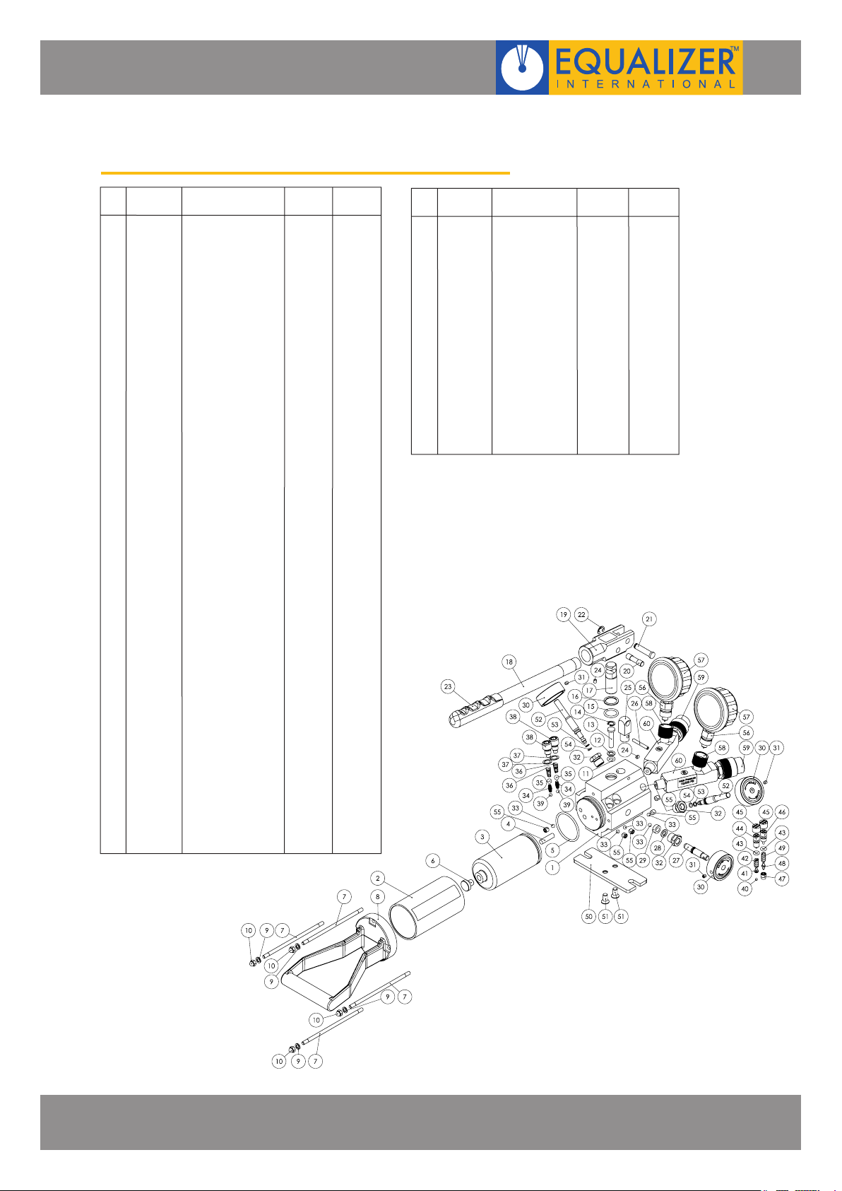
HP350D HYDRAULIC TWIN PORT SEALED HAND PUMP
ITEM
01
02
03
04
05
06
07
08
09
10
11
12
13
14
15
16
17
18
19
20
21
22
23
24
25
26
27
28
29
30
31
32
33
34
35
36
37
38
39
40
41
42
43
44
45
46
47
48
49
PART No.
720101-01
710601-01
715100-01
725200-01
715300-01
715400-01
715500-01
715600-01
715700-01
715800-01
DESCRIPTION
PUMP HOUSING
RESERVOIR
SERVICE KIT A:
- RESERVOIR BLADDER
- OIL FILTER
- O-RING
- REFILLING PLUG
SERVICE KIT B:
- SCREW
- TAIL BASE
- SPRING WASHER
- NUT
SERVICE KIT C:
- O-RING
- BACK-UP RING
- H.P. PISTON
- SNAP RING
- O-RING
- BACK-UP RING
- L.P. PISTON
SERVICE KIT D:
- HANDLE
- YOKE
- PISTON PIN
- YOKE PIN
- RETAINING RING
- HANDLE GRIP
- SCREW
SERVICE KIT E:
- YOKE BASE
- SPRING PIN
SERVICE KIT F:
- RELEASE VALVE
SCREW
- WASHER
- SEAL
- RELEASE KNOB
- SCREW
- COUPLERS
- CHECK BALL
SERVICE KIT G:
- SPRING
- STEEL BALL
- OUTLET BALL
SPRING
- COPPER WASHER
- VALVE COVER SCREW
- STEEL BALL
SERVICE KIT H:
- STEEL BALL
- SPRING END CAP
- L.P. SPRING
- O-RING
- OVERLOAD COVER
SCREW
- CAP
- OVERLOAD COVER
SCREW
- CONE SEAT
- CONE
- LONG SEPARATOR
SPRING
KIT
QUANTITY
01
01
01
01
04
01
04
04
01
01
01
01
01
01
01
01
01
01
01
01
01
01
01
01
01
01
01
01
01
01
01
02
02
02
02
02
02
01
01
01
02
01
02
01
01
01
01
PUMP
QUANTITY
01
01
01
01
01
01
04
01
04
04
01
01
01
01
01
01
01
01
01
01
01
01
01
01
01
01
01
01
01
01
01
01
01
02
02
02
02
02
02
01
01
01
02
01
02
01
01
01
01
01
01
01
01
04
04
01
02
01
01
01
01
01
01
01
PUMP
QUANTITY
ITEM
PART No.
715900-01
50
51
726000-01
52
53
54
30 02
31
32
716100-01
55
33
716200-01
56
57
716300-01
58
59
60
DESCRIPTION
SERVICE KIT I:
- BASE PLATE
- SCREW
SERVICE KIT J:
- VALVE SCREW
- BACK-UP RING
- O-RING
- RELEASE KNOB
- SCREW
- COUPLERS
SERVICE KIT K:
- SCREW
- CHECK BALL
SERVICE KIT L:
- GAUGE COUPLER
MALE
- GAUGE
SERVICE KIT M:
- GAUGE COUPLER
FEMALE
- COUPLER
- PORT GAUGE
ADAPTOR
KIT
QUANTITY
01
02
02
02
02
02
02
04
04
02
02
02
02
02
HYDRAULIC SEALED HAND PUMPS
OPERATOR INSTRUCTION MANUAL
PAGE 17
Page 20
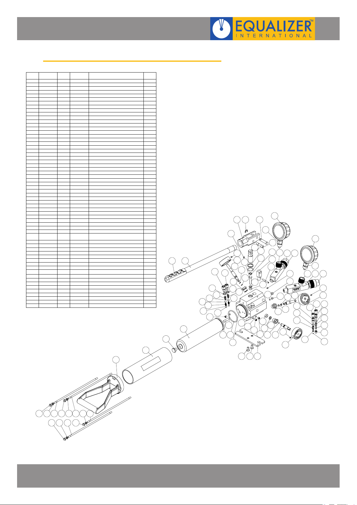
HP550D HYDRAULIC TWIN-PORT SEALED HAND PUMP
ITEM
SUP PART
NO.
1
F0366
2
D0853
GA050
3
G0108
4
5
E0164
6 I0035
7
GA127
G0126
8
E0165
9
10
C0617Z
B1177
11
H0053Z
12
13
J0156
G0105
14
E1604
15
16 H0050
H0052Z
17
K0001 F/K/R
18
19
J0045
K0003
20
J0001
21
22
J0002
H0006Z
23
K0002 G/Q
24
K0011
25
E0006
26
27
J0140
G0009
28
H0007Z
29
30
G0010
31
E1749
E1748
32
J0389
33
H0340Z
34
35
C0687A
36 H0189
E1721Z
37
38
G0270
G0086
39
H0003Z
40
H0215Z
41
CP212
42
M0031-
43
44 E174S
45
CP211
CP331
46
G0564
47
M0018
48
49
G0102
E0772
50
D0854
51
52
G0664
53
C0686
54
E0389Z
E0005Z
55
56 I0001Z
H0048Z
57
H0338Z
58
F0335
59
J0036
60
61 H0325
NO
EG
KIT PART NO
-
707001-01
-
708002-01 RESERVOIR1
711001-01
C
C
711101-01
C
711201-01
711301-01
C
C
711401-01
C
711501-01
C
711601-01
E
712201-01
E
712301-01
F
F
F
F/J
F/J
F/J
G
G
G
G
G
H
H
H
H
H
H
H
H
H
H
I
I
J
J
J
K
Q
L
L
M
M
M
N
A/N
A/N
A/N
O
D/O
D/O
D/O
D/O
D/O
D/K/O
P
B/P
B/P
B/P
712901-01
712601-01
712501-01
713001-01
300401-01
712701-01
712801-01
713501-02
713601-02
713701-02
713801-02
713901-02
707029-01
714001-02
714101-02
714201-01
714401-02
714501-02
714601-02
377201-01
377301-01
377401-01
707044-01
714901-01
715001-01
720401-01
720501-01
720601-01
713201-03
707067-01
707072-01
302501-01
302502-01
707072-01
771110-01
708001-01
710201-01
707003-01
710501-01
708004-01
201202-01
712001-01
711701-01
711801-01
711901-01
707013-01
708003-01
710701-01
707009-01
710901-01
RELEASE VALVE SCREW
VALVLE COVER SCREW
OVERLOAD COVER SCREW
LONG SEPARATOR SPRING
OVERLOAD COVER SCREW
GAUGE COUPLER MALE
PORT GAUGE ADAPTOR
GAUGE COUPLER FEMALE
3/8" NPT COUPLER 10kPSI
RESERVOIR BLADDER
DESCRIPTION
PUMP HOUSING
O-RING
BACK-UP RING
H.P. PISTON
SNAP RING
O-RING
BACK-UP RING
L.P. PISTON
YOKE BASE
SPRING PIN
WASHER
SEAL
RELEASE KNOB
M5 SCKT SET SCREW
COUPLERS
CHECK BALL
SPRING
STEEL BALL
OUTLET BALL SPRING
COPPER WASHER
STEEL BALL
STEEL BALL
SPRING END CAP
L.P. SPRING
O-RING
CAP
CONE SEAT
CONE
BASE PLATE
SCREW
VALVE SCREW
BACK-UP RING
O-RING
SCREW
SCREW
GAUGE
OIL FILTER
O-RING
REFILLING PLUG
HANDLE
HANDLE GRIP
YOKE
PISTON PIN
YOKE PIN
RETAINING RING
SCREW
SCREW
TAIL BASE
SPRING WASHER
NUT
59
QTY.
2
1
1
1
1
1
1
1
1
1
1
1
1
1
3
3
3
5
2
2
2
2
2
2
1
1
1
2
1
2
1
1
1
1
1
2
2
2
2
4
1
2
2
2
2
2
1
1
1
1
1
1
1
1
1
1
2
4
1
4
4
52
51
47
50
53
56
57
5
38
39
21
18
18
36 36 35
9
4
40
16
15
23
22
21
20
20
19
24
40
37
23
17
22
19
24
491848
1
43
55
42
54
8
6
45
44
7
3
18
14
13
40
18 12
46
10
11
57
41
37
40
38
29
39
17
17
28
27
16
15
43
42
4645 44
16
15
30
34
30
28
33
32
31
26
25
61 60 58 61 60 58 5860
61586061
HYDRAULIC SEALED HAND PUMPS
OPERATOR INSTRUCTION MANUAL
PAGE 18
Page 21
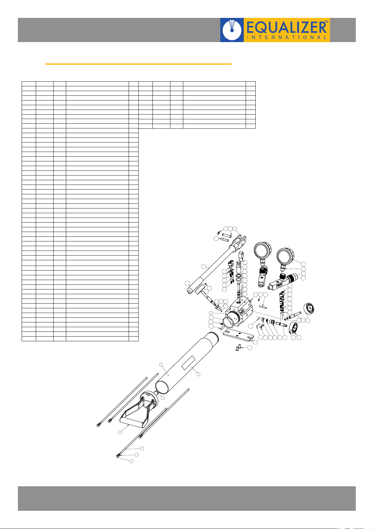
HP1000D HYDRAULIC TWIN-PORT SEALED HAND PUMP
ITEM NO.
PART NO
1 520001-01
2 710501-01
3 520002-01
4 710701-01
5 520003-01
6 707009-01
7 710901-01
8 070264-01
9 707001-01
10 710201-01
11 707003-01
12 712801-01
13 713201-03
14 707013-01
15 711001-01
16 711101-01
17 711201-01
18 711301-01
19 711401-01
20 711501-01
21 711601-01
22 712201-01 E
23 712301-01 E
24 712001-01
25 711701-01
26 711801-01
27 711901-01
28 708004-01
29 707029-01 G/Q
30 713501-02 G
31 713601-02 G
32 713701-02 G
33 713801-02 G
34 713901-02 G VALVLE COVER SCREW 2
35 714001-02
36 714101-02
37 714201-01
38 714401-02
39 714501-02
40 714601-02
41 377201-01
42 377301-01
43 377401-01
44 707044-01
45 707067-01
46 707072-01
47 714901-01
48 715001-01
49 771110-01
50 707072-01
51 302501-01
52 070054-01
54 720401-01
55 720501-01
KIT
T
A/N
-
B/P
U
B/P
B/P NUT
-
-
A/N
A/N
F/K/R
K
D/K/O
C
C
C
C
C
C
C
D/O
D/O
D/O
D/O
O HANDLE
H
H
H
H
H
H
H
H
H
H
Q
M
I
I
M
L
L
-
J
J
DESCRIPTION
RESERVOIR BLADDER 1000
REFILLING PLUG
RESERVOIR 1000
TAIL BASE
SPRING WASHER
HP1000D STICKER
PUMP HOUSING
OIL FILTER
CHECK BALL
BACK-UP RING
H.P. PISTON
SNAP RING1
BACK-UP RING
L.P. PISTON
YOKE BASE
SPRING PIN
PISTON PIN1
YOKE PIN
RETAINING RING
STEEL BALL
STEEL BALL
OUTLET BALL SPRING
COPPER WASHER
STEEL BALL
SPRING END CAP
L.P. SPRING
OVERLOAD COVER SCREW
CONE SEAT 1
LONG SEPARATOR SPRING 1
OVERLOAD COVER SCREW
GAUGE COUPLER FEMALE
BASE PLATE
3/8" NPT COUPLER 10kPSI
GAUGE COUPLER MALE
QC SEALED TOP PLATE STICKER
VALVE SCREW 2
BACK-UP RING
SCREW
O-RING
SCREW
SCREW
O-RING
O-RING
YOKE
SPRING
O-RING
CAP
CONE
SCREW
SCREW
GAUGE
QTY.
1
1
1
1
4
4
4
1
1
1
1
4
4
1
1
1
1
1
1
1
1
1
1
1
1
1
2
2
2
2
2
1
1
1
2
1
2
1
1
1
2
1
2
2
2
2
2
2
ITEM NO.
56 720601-01
57 302502-01
59 713001-01
60 300401-01
61 712901-01
62 712701-01
63 712601-01
64 712501-01
65 201202-01
PART NO
KIT
J
M
F/J RELEASE KNOB
F/J
F
F/J
F
F
D/O
DESCRIPTION
O-RING
PORT GAUGE ADAPTOR
M5 SCKT SET SCREW
RELEASE VALVE SCREW 1
COUPLERS
WASHER 1
SEAL
HANDLE GRIP 1
25
28
65
60
59
9
11
13
10
QTY.
2
2
3
3
3
1
2627
24
22
34
33
32
31
30
556254
56
21
20
19
17
18
16
15
45 60 23
12
12
13
47
48
51
50
57
49
40
38
44
43
42
36
41
35
55 54 59
596061626364
HYDRAULIC SEALED HAND PUMPS
OPERATOR INSTRUCTION MANUAL
3
1
2
4
5
6
7
PAGE 19
Page 22
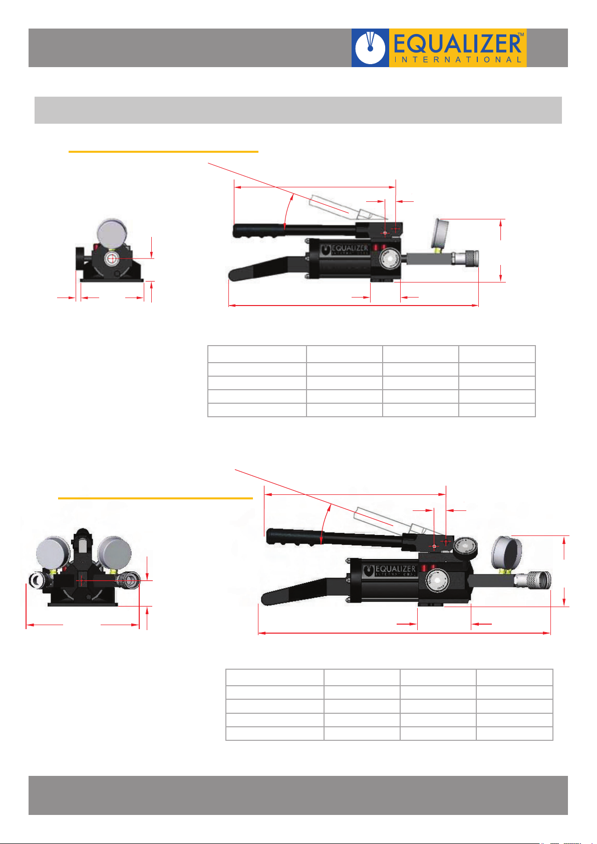
9. WEIGHTS AND DIMENSIONS
9.1 HP350S, HP550S & HP1000S
B
10 mm
(0.39")
140 mm
(5.51")
51.5 mm
(2.03")
23 mm
0-40°
(0.91")
141 mm
(5.55")
71.5 mm
(2.81")
A
HP350S HP550S HP1000S
OVERALL LENGTH (A) 554.0mm (21.81”) 643.0mm (25.31”) 867.0mm (34.13”)
HANDLE LENGTH (B) 360.0mm (14.17”) 490.0mm (19.29”) 537.0mm (21.14”)
PUMP WEIGHT 4.0kg (8.8lb) 4.6kg (10.1lb) 5.7kg (12.6lb)
GROSS KIT WEIGHT 10.4kg (11.2lb) 11.2kg (12.1lb) 13.7kg (14.6lb)
9.2 HP350D, HP550D & HP1000D
51.5 mm
(2.03")
227 mm
(8.94")
OVERALL LENGTH (A) 580.0mm (22.83”) 669.0mm (26.34”) 893.0mm (35.16”)
HANDLE LENGTH (B) 360.0mm (14.17”) 490.0mm (19.29”) 537.0mm (21.14”)
PUMP WEIGHT 4.4kg (13.2lb) 5.0kg (11.0lb) 6.1kg (13.4lb)
GROSS KIT WEIGHT 5.1kg (11.2lb) 5.5kg (12.1lb) 6.6kg (14.6lb)
B
0-40°
A
HP350D HP550D HP1000D
23 mm
(0.91")
141 mm
(5.55")
110 mm
(4.33")
HYDRAULIC SEALED HAND PUMPS
OPERATOR INSTRUCTION MANUAL
PAGE 20
Page 23
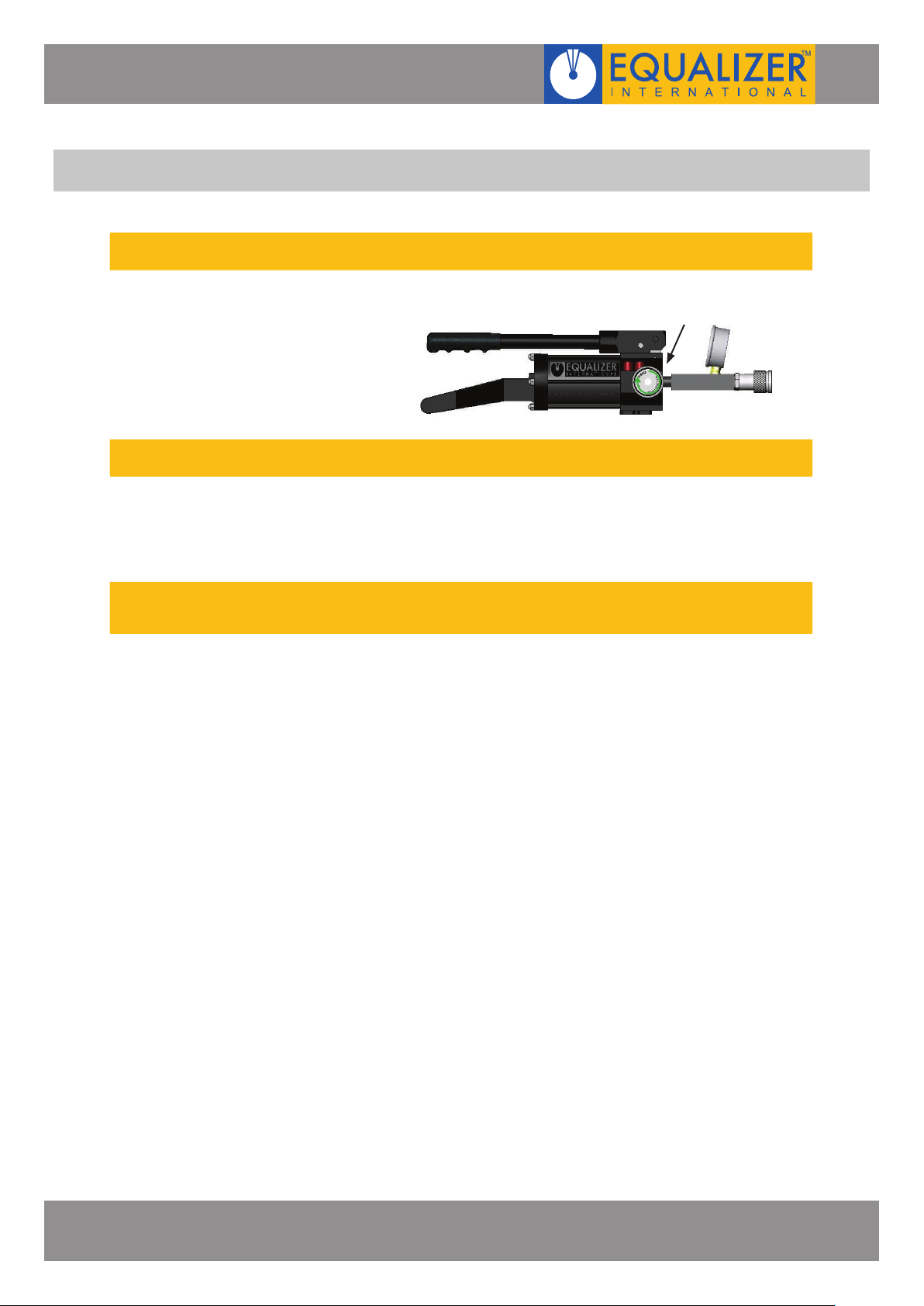
10. TROUBLESHOOTING
Problem: Hoses are connected but the tool does not advance. The pressure on the pump handle is minimal.
The release valve is in the retract
(open) position (and the control
valves are open on the HP-D)
Problem: Hoses are connected and the pump quickly reaches maximum pressure but the tool has not advanced
One or more of the connectors are
not fully tightened and the
hydraulic oil cannot pass through
from the pump to the cylinder
Problem: Hoses are connected and the tool advances but there is minimal pressure on the pump handle and the
xxxxxxxxxhandle is rising back of its own accord
There is dirt or a damaged valve
seat within the pump unit
Close the release valve (and the control valves
on the HP-D)
Check all connectors are fully tightened and the release valve is in the
fully closed position
The pump should be sent to an authorised Equalizer distributor for repair
CLOSE RELEASE
VALVE
HYDRAULIC SEALED HAND PUMPS
OPERATOR INSTRUCTION MANUAL
PAGE 21
Page 24
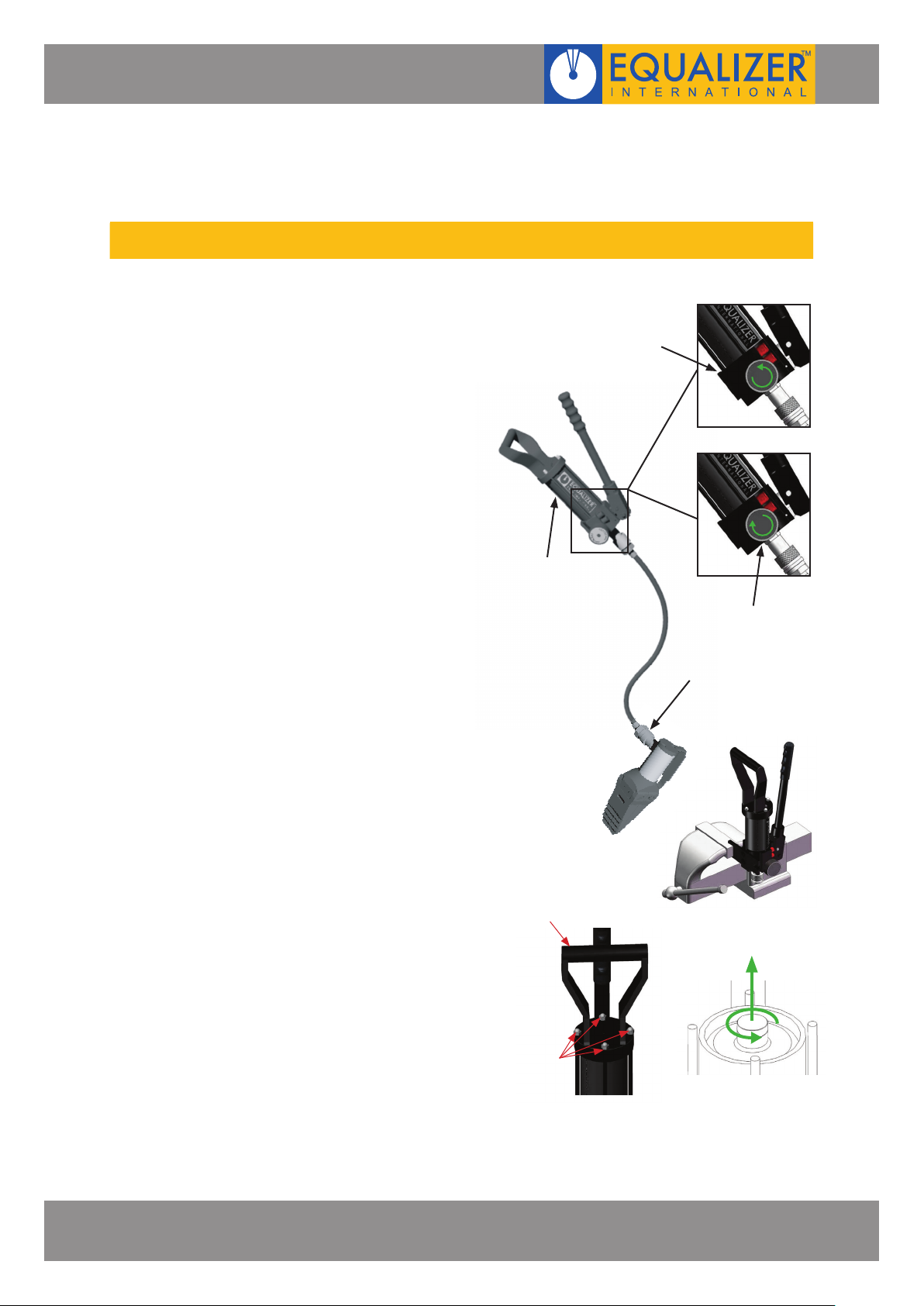
Problem: The tool the hand pump is driving is advancing but does not reach full pressure
Air could be present in
the hydraulic system
Use the airlock removal
procedure as follows:
1. Connect the hand pump to the
tool with the hydraulic hose
2. Close the release valve on the
pump, and prime the pump
until the hydraulic cylinder
is fully extended and a small
pressure is achieved
3. With the hand pump held
above the tool and the tool
in an upright position, open
the release valve causing any
air that is within the system
to be forced up through the
pump and vented into the oil
reservoir
4. Repeat steps 1 - 3 three or
four times to ensure that all air
is removed from the system
and the tool will reach full
working pressure
5. Disconnect the hand pump
from the hydraulic hose, grip
the baseplate of the hand
pump body in a vice with the
pump body vertical and the
main handle at the top
OPEN RELEASE
VALVE
OIL
RESERVOIR
CLOSE RELEASE
VALVE
ACTUATOR
COUPLER
HYDRAULIC SEALED HAND PUMPS
OPERATOR INSTRUCTION MANUAL
6. Remove the four nuts holding
the main handle and lift off
7. Grip the relling plug with
pliers and extract it by pulling
and twisting simultaneously.
Ensure the reservoir body is
held down when removing the
relling plug as pulling up on
the reservoir body will release
the bladder within, and oil will
spill out.
8. Fill the reservoir to the top with
a good quality hydraulic oil of
the grade 15 cSt
9. Reinsert the relling plug, wipe
away any oil, and reassemble
by reversing the disassembly
process
MAIN
HANDLE
NUTS
PAGE 22
 Loading...