

Page 1
OPERATOR INSTRUCTION MANUAL
FA1TM
FLANGE
ALIGNMENT
TOOL
EQUALIZER INTERNATIONAL LTD
www.equalizerinternational.com
Page 2

OPERATOR INSTRUCTION MANUAL
CONTENTS
1. INTRODUCTION
2. TOOL SAFETY
2.1 GENERAL SAFETY
2.2 PERSONNEL COMPETENCY
2.3 DISCLAIMER
2.4 DEFINITION OF TERMS
2.5 HAZARDS
3. FLANGE MISALIGNMENT DETERMINATION PROCEDURE
3.1 LATERAL MISALIGNMENT
4. FA1TM MECHANICAL FLANGE ALIGNMENT TOOL
4.1 TOOL CAPABILITIES
4.2 RANGE OF APPLICATION
4.3 TOOL FUNCTION
4.4 KIT CONTENTS
4.5 TOOL DIMENSIONS
4.6 TOOL MAINTENANCE
5. RANGE OF APPLICATION
5.1
5.2 ASME B16.5, ASME B16.47, DIN WELD NECK
FLANGE TABLES
5.3 SPO FLANGE TABLE
BS10, API6BX, API6B WELD NECK FLANGE TABLES
IM_FA1TM_Rev08_A4
6. TROUBLESHOOTING
6.1 FA1TM TROUBLESHOOTING
7. REGULATORY INFORMATION
7.1 REGISTERED HEAD OFFICE
8. PARTS LISTS & SERVICE KITS
31/10/2018
FA1TM
1
FLANGE ALIGNMENT TOOL
Page 3
OPERATOR INSTRUCTION MANUAL
IM_FA1TM_Rev08_A4
1.
INTRODUCTION
The Equalizer FA1TM TOOL is an aid of use in
normal maintenance and installation procedures to
enable the realignment of misaligned anges within
respective working capacities. For example, the tool
can be used to assist in the replacement of ring and
other types of ange joint.
The use of these instructions will promote safe use,
and maximise the service life of the tools.
It is essential that the user familiarises themselves
with the contents of this manual prior to using the
tool.
This manual contains information for the following
tools:
• FA1TM Flange Alignment Tool
2.
SAFETY INFORMATION
2.1
GENERAL SAFETY
These instructions cover the safe operation and
maintenance of THE EQUALIZER FA1TM FLANGE
ALIGNMENT tools. The use of these tools should be as
part of a broader task-based risk assessment, which
should be carried out by the operation supervisor or
other competent person.
Failure to comply with the safety information
contained within this manual could result in personal
injury or equipment damage. Read all instructions,
warnings and cautions carefully, and follow all safety
precautions.
The safety of the operator, any assisting personnel
and the general public is of paramount importance.
Always work in accordance with applicable national,
local, site & company-wide safety procedures.
2.2
PERSONNEL COMPETENCY
Only personnel deemed competent in the use of
mechanical and hydraulic equipment should use
these tools.
2.3
DISCLAIMER
Equalizer cannot be held responsible for injury or
damage resulting from unsafe product use, lack of
maintenance or incorrect product and/or system
operation. If in doubt as to the safety precautions
and applications, contact Equalizer using the contact
details at the back of this manual.
FA1TM
2
FLANGE ALIGNMENT TOOL
Page 4
OPERATOR INSTRUCTION MANUAL
IM_FA1TM_Rev08_A4
2.4
DEFINITION OF TERMS
A CAUTION is used to indicate correct operating or
maintenance procedures and practices to prevent damage
to, or destruction of equipment or other property.
A WARNING indicates a potential danger that requires
correct procedures or practices to avoid personal injury.
A DANGER is only used when your action or lack of action
may cause serious injury or even death.
DO: an illustration showing how the tool should
be used.
DON’T: an illustration showing an incorrect way
to use a tool.
WARNING: Applying pressure to a damaged
hose may cause it to rupture.
WARNING: Immediately replace worn or
damaged parts. Use only genuine Equalizer parts
from approved distributors or service centres.
Equalizer parts have been engineered and
manufactured to be t-for-purpose.
DANGER: To minimise risk of personal injury keep
hands and feet away from the tool and workpiece
during operation.
WARNING: Always wear suitable clothing and
Personal Protective Equipment (PPE). Do not
handle pressurised hoses; escaping oil under
pressure can penetrate the skin, causing serious
injury. Seek medical attention immediately if oil
penetration is suspected.
WARNING: Only pressurize complete and fully
connected hydraulic systems. Do not pressurize
systems that contain unconnected couplers.
2.5
HAZARDS
WARNING: ensure all hydraulic components are
rated to a safe working pressure of 700
000 psi
(10
WARNING: Do not overload equipment. The risk
of hydraulic overloading can be minimised by using
the Equalizer Hand Pump, which has a factory-set
safety valve preventing the safe working pressure
being exceeded.
If alternative hydraulic pumps are used, ensure
that there are adequate systems to limit the the
working pressure to 700 bar (10,000 psi).
CAUTION: ensure components are protected
from external sources of damage, such as excessive
heat, ame, moving machine parts, sharp edges
and corrosive chemicals.
CAUTION: Take care to avoid sharp bends and
kinks in hydraulic hoses. Bends and kinks can
cause severe back-up pressure and cause hose
failure. Protect hoses from dropped objects; a
sharp impact may cause internal damage to hose
wire strands. Protect hoses from crush risks, such
as heavy objects or vehicles; crush damage can
cause hose failure.
CAUTION: Do not lift hydraulic equipment by the
hoses or couplers. Use only the designated carrying
handles.
bar
).
CAUTION: Lubricate tools as directed in this
manual prior to operation. Use only approved
lubricants of high quality, following the lubricant
manufacturers instructions.
CAUTION: Only use the designated anchor point
for xing the lanyard. Do not attach the lanyard to
the plastic handle.
DANGER: Care should be taken when using the
lanyard to avoid entanglement with body parts.
The vibration total value to which this tool is
subjected does not exceed 2.5 m/s
2
.
FA1TM
3
FLANGE ALIGNMENT TOOL
Page 5
OPERATOR INSTRUCTION MANUAL
3.
FLANGE MISALIGNMENT
DETERMINATION
PROCEDURE
The tool being used must not be attached to a
anged joint prior to the misalignment procedure
being carried out.
3.1
LATERAL MISALIGNMENT
1. Loosen and remove every second bolt around
the ange. Continue with this until misalignment
occurs.
IM_FA1TM_Rev08_A4
A anged joint, once broken down, may spring
out of alignment at any point or in any direction
around its circumference. Misalignment may not
occur until only a few bolts remain.
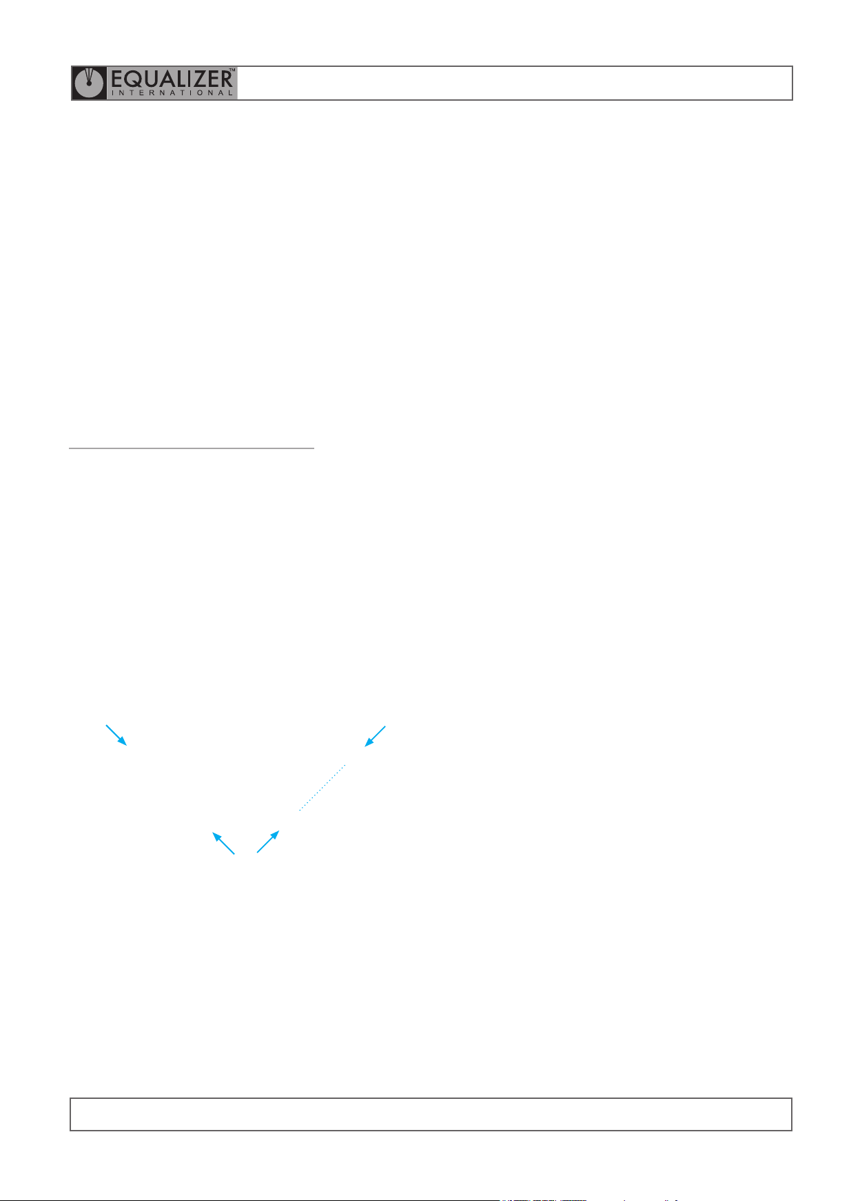
2. At this point the direction of any misalignment
should become obvious. The alignment tool
being used should be attached at the maximum
point of misalignment (point A or B in the
examples shown below).
POINT A
POINT B
POINT A
POINT B
FA1TM
4
FLANGE ALIGNMENT TOOL
Page 6

OPERATOR INSTRUCTION MANUAL
4.
FA1TM
MECHANICAL FLANGE
ALIGNMENT TOOL
The FA1TM Flange Alignment Tool uses mechanical torque
to advance the screw bolt and align the anges.
4.1
TOOL CAPABILITIES
Maximum aligning force of tool = 1 T (10 kN)
4.2
IM_FA1TM_Rev08_A4
4.3
FA1TM TOOL FUNCTION
FA1TM GENERAL GUIDANCE
1. The FA1TM is secured to the lower of the
two anges by fully inserting the lift hool
into the bolt-hole at the point of greatest
misalignment.
2. The drop leg release knob is slackened and
the drop leg is adjusted down to the pipe
while the tool is held level in the bolt-hole.
3. The drop leg release knob is then tightened
until rm.
4. The strap and buckle are attached to the drop
leg and around the pipe for added
security.
5. The crank handle is then turned clockwise
until the driven wedge comes into contact
with the circumference of the opposite ange.
RANGE OF APPLICATION
MINIMUM AND MAXIMUM FLANGE SIZES
Dimension A: must be between 14 mm and
82 mm (0.55” and 3.23”).
Dimension B: bolt-hole diameter must be 16 mm
(0.63”) or greater
DIMENSION
A
DIMENSION
B
CRANK
HANDLE
RELEASE
KNOB
MINI
RATCHET &
STRAP
DRIVEN
WEDGE
FA1TM
5
FLANGE ALIGNMENT TOOL
Page 7
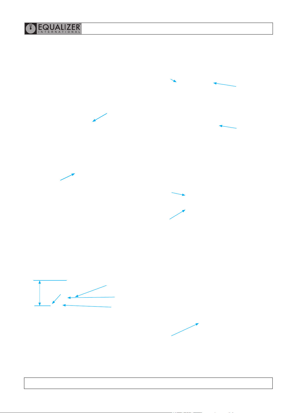
ACTUATING THE FA1TM
OPERATOR INSTRUCTION MANUAL
Rotate the crank handle clockwise until the driven
wedge makes contact with the opposite ange.
IM_FA1TM_Rev08_A4
Carry out the Flange Misalignment Determination
Procedure (see Section 3) to determine the points of
maximum misalignment.
In this example the points of maximum misalignment
are the top and bottom of the joint.
POINT OF MAX.
MISALIGNMENT
POINT OF MAX.
MISALIGNMENT
CRANK
HANDLE
DRIVEN
WEDGE
OPPOSITE FLANGE
Thread the strap through the aperture on the base
of the drop leg as shown.
STRAP
APERTURE
Guide the lift hook into the bolt-hole at the point of
maximum misalignment.
Adjust the drop leg down onto the pipe by slackening
the release knob in an anticlockwise direction.
The tool should be held up level within the bolt-hole
during adjustment. NB: The tool must be parallel to
pipe during operation.
LIFT HOOK
RELEASE
PARALLEL
KNOB
DROP LEG
The drop leg release knob is then tightened until
rm.
STRAP
Feed the open end of the strap through the buckle
mechanism as shown.
Close the clasp to secure strap.
FEED THROUGH
STRAP
FA1TM
6
FLANGE ALIGNMENT TOOL
Page 8
OPERATOR INSTRUCTION MANUAL
IM_FA1TM_Rev08_A4
Now that everything is secured, rotate the handle
clockwise to apply pressure to the circumference
of the opposite ange & bring the ange joint in
alignment.
WARNING: Do not exceed hand pressure on
the crank handle
Once in alignment the bolts may be inserted and
tightened. After replacing all of the bolts (apart from
the bolt which will go into the bolt-hole in which the
FA1TM is located) remove the tool by reversing the
previous steps. Insert the last bolt and tighten.
4.4
FA1TM KIT CONTENTS
Product Code: FA1TMSTD
1 x FA1TM Tool
1 x Mini Ratchet Strap
1 x Instruction Manual
Box Dimensions:
180.0mm x 330.0mm x 220.0mm
(7.1” x 13.0” x 8.7”)
Tool only Weight: 2.1 kg (4.63 lb)
Gross Kit Weight: 2.3 kg (5.07 lb)
WARNING: Care should be taken not to drop
any of the component parts when removing
them from the ange joint. This action will
prevent injuries to either the operator’s lower
limbs, or to passers-by.
FA1TM
7
FLANGE ALIGNMENT TOOL
Page 9
OPERATOR INSTRUCTION MANUAL
IM_FA1TM_Rev08_A4
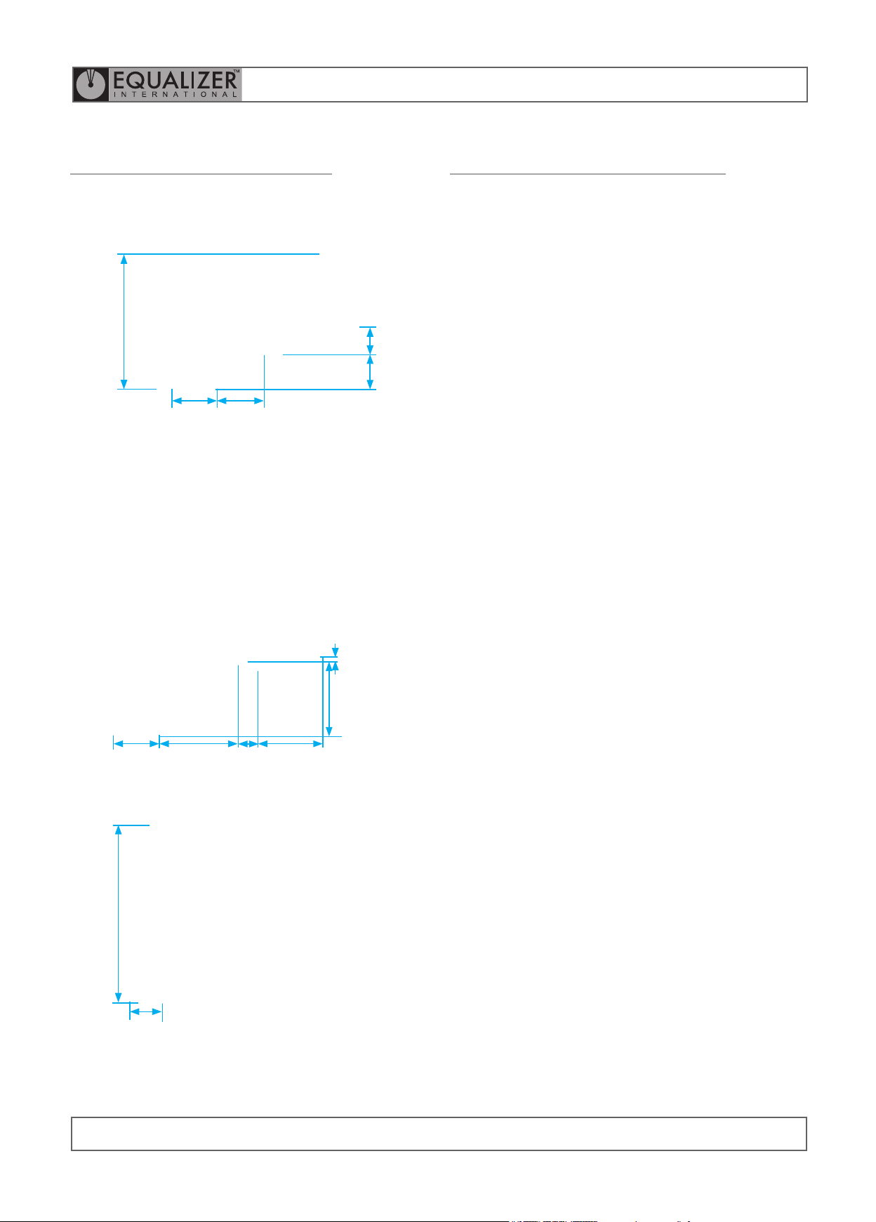
4.5
FA1TM TOOL DIMENSIONS
MINIMUM EXTENSION
151 mm
(5.94”)
50 mm
(1.97”)
MAXIMUM EXTENSION
54 mm
(2.13”)
31 mm
(1.22”)
38 mm
(1.50”)
4.6
FA1TM TOOL MAINTENANCE
INSPECTION
A thorough inspection should be carried out prior
to usage, storage or transportation to ensure the
completeness and condition of the tool.
Inspection should include:
• visual inspection of the outer parts of the tool,
checking for obvious damage, degradation or
missing parts.
Cleaning and servicing should be undertaken as
required prior to the tool being used, stored or
transported.
CLEANING
To lightly clean the tool, wipe gently with a damp
cloth.
194 mm
(7.64”)
50 mm
(1.97”)
89 mm
(3.50”)
21 mm
(0.83”)
72 mm
(2.83”)
5 mm
(0.2”)
82 mm
(3.23”)
If more thorough cleaning is required (for example
following immersion in water) carry out the following
cleaning procedure:
• strip the tool down, observing the schematics in
section 8
• clean the components using detergent, following
the manufacturer’s guidelines
• rinse the components to remove traces of
detergent
• dry the component thoroughly
Inspect, service and lubricate the tool immediately
after the cleaning process.
SERVICING
Replace missing, worn or damaged parts. Use only
genuine Equalizer parts from approved distributors
or service centres. Equalizer parts have been
engineered and manufactured to be t for purpose.
FA1TM
35 mm
(1.38”)
Grease all moving parts by following the Lubrication
Procedure prior to usage, storage or transportation.
Ensure wedges, pins and legs remain grit free and
that parts move freely.
8
FLANGE ALIGNMENT TOOL
Page 10

OPERATOR INSTRUCTION MANUAL
Secure the tool upright on a bench.
Using a small at screwdriver, lever out one circlip
and unscrew 6 x 6mm hex screws.
Remove cover plate and remov e any dirt or corrosion
from moving parts.
Inspect components for wear and damage, replace if
necessary! If there’s no damage present, then they
can be greased and re-assembled by reversing the
previous steps.
Recommended grease –
Rocol Sapphire Hi-Load or equivalent good quality hi
load bearing grease.
COVER
PLATE
HEX
SCREW
DRIVEN
WEDGE
CIRCLIP
DRIVING
WEDGE
NEEDLE
BEARINGS
IM_FA1TM_Rev08_A4
STORAGE AND TRANSPORTATION
Equalizer tools should be stored in a cool, dry
place. Tools should always be cleaned, serviced and
lubricated prior to storage. Ensure that tools are
stored in their designated packing cases.
LONG-TERM STORAGE - MAINTENANCE PLAN
1. Rub components down with a dry cloth to remove
moisture.
2. Coat EVERY surface and contact point with a corrosion
inhibitor. Where necessary, coat inside and outside of
component
3. Nuts and threads must also be coated with a corrosion
inhibitor.
4. Once surfaces have been coated, seal individual
components in clear plastic bags or clear vacuum
bags or clear shrink wrap.
NOTE: bags/shrink wrap must be clear for visibility.
Take care when using shrink wrap that the tool is/
components are still easy to see.
5. Remove all or, where not vacuum sealed, as much air
from bags as possible.
6. Once bags have been closed and sealed DO NOT re-
open. Any visual inspections must be done with closed
and sealed bags. If bags are opened the components
will have to be dried, re-coated and re-sealed in bags/
shrink wrap.
7. Replace silica gel (100g) EVERY TIME the case is
opened.
NOTE: depending on moisture content of air, silica gel
should be changed weekly.
8. Visually inspect kits after 30-days and every 30-days
thereafter. Remember to replace silica gel before
closing case.
FA1TM
9
FLANGE ALIGNMENT TOOL
Page 11
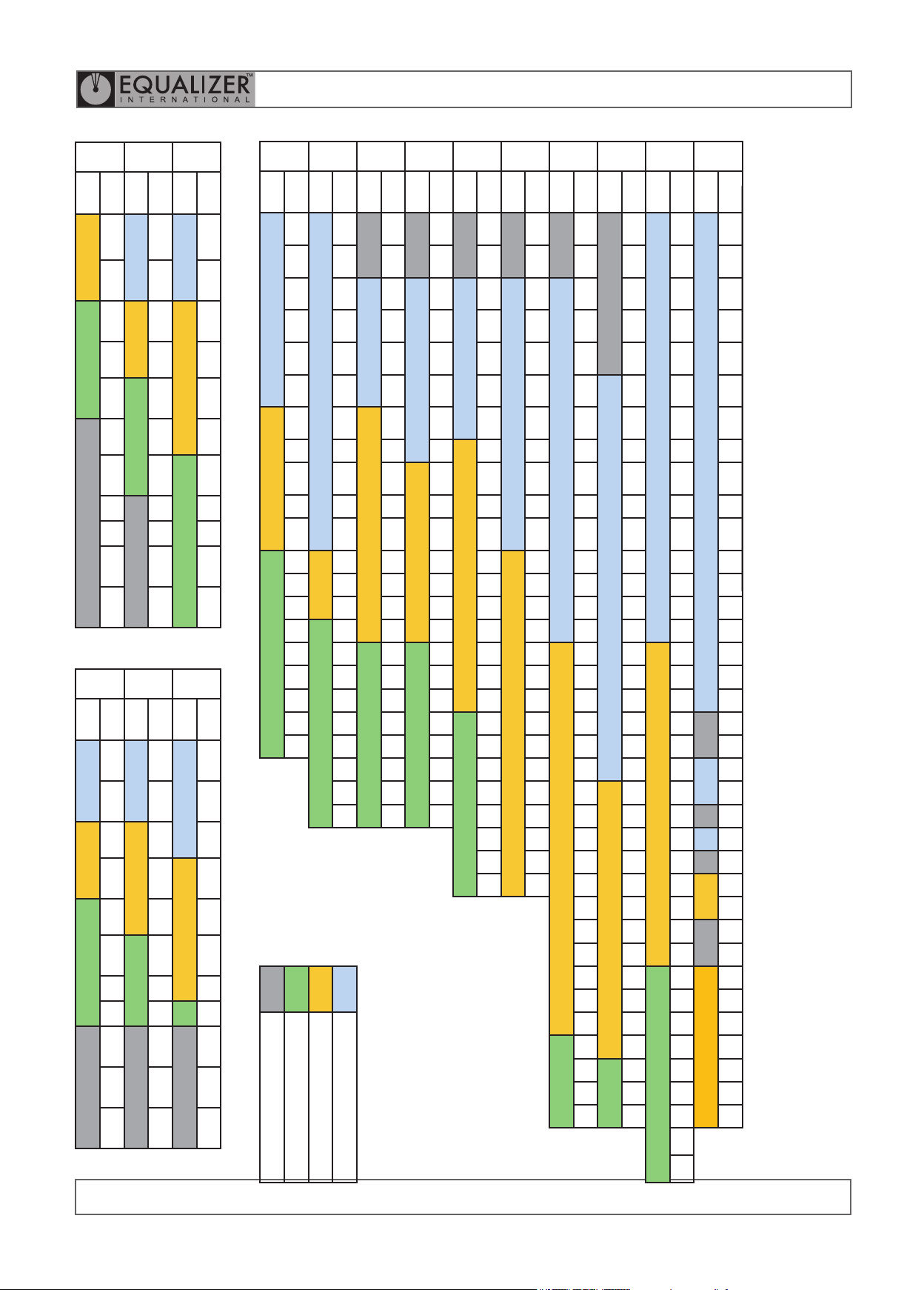
CLASS
20K
TOOL FA4TM FA9TE
NPS 1 13-16" 2 1-16" 2 9-16" 3 1-8" 4 1-16" 5 1-8" 7 1-16" 9" 11" 13 5-8" 16 3-4"
CLASS
15K
TOOL FA1TM FA4TM FA9TE
NPS 1 13-16" 2 1-16" 2 9-16" 3 1-8" 4 1-16" 5 1-8" 7 1-16" 9" 11" 13 5-8" 16 3-4"
CLASS
10K
TOOL FA1TM FA4TM FA9TE
OPERATOR INSTRUCTION MANUAL
API6BX WELD NECK FLANGE RANGE OF APPLICATION
NPS 1 13-16" 2 1-16" 2 9-16" 3 1-8" 4 1-16" 5 1-8" 7 1-16" 9" 11" 13 5-8" 16 3-4"
CLASS T
TOOL FA1TM FA4TM FA9TE NOT SUITABLE FOR TOOLS
NPS
CLASS S
TOOL FA1TM FA4TM FA9TE SUITABLE FOR FA4TM TOOL
NPS
CLASS R
TOOL FA1TM FA4TM FA9TE
NPS
CLASS K
TOOL FA1TM FA4TM FA9TE
NPS
CLASS J
TOOL FA1TM FA4TM FA9TE
NPS
CLASS H
TOOL FA1TM FA4TM
NPS
CLASS F
TOOL FA1TM FA4TM FA9TE
NPS
CLASS E
TOOL FA1TM FA4TM FA9TE
NPS
CLASS D
TOOL FA1TM FA4TM FA9TE
IM_FA1TM_Rev08_A4
5.1 BS10 FLANGE RANGE OF APPLICATION
CLASS A
TOOL FA1TM FA1TM FA4TM FA4TM
NPS
NPS
5. RANGE OF APPLICATION
1/2" 3/4" 1" 1 1/4" 1 1/2" 2" 2 1/2" 3" 3 1/2" 4" 4 1/2" 5" 6" 7" 8" 9" 10" 11" 12" 13"
1/2" 3/4" 1" 1 1/4" 1 1/2" 2" 2 1/2" 3" 3 1/2" 4" 4 1/2" 5" 6" 7" 8" 9" 10" 11" 12" 13" 14" 15" 16"
1" 1 1/4" 1 1/2" 2" 2 1/2" 3" 3 1/2" 4" 5" 6" 7" 8" 9" 10" 12" 13" 14" 15" 16" 17" 18" 19" 20"
1" 1 1/4" 1 1/2" 2" 2 1/2" 3" 3 1/2" 4" 5" 6" 7" 8" 9" 10" 12" 13" 14" 15" 16" 17" 18" 19" 20"
1 1/4" 1 1/2" 2" 2 1/2" 3" 3 1/2" 4" 5" 6" 7" 8" 9" 10" 12" 13" 14" 15" 16" 17" 18" 19" 20" 21" 22" 23" 24"
1 1/4" 1 1/2" 2" 2 1/2" 3" 3 1/2" 4" 5" 6" 7" 8" 9" 10" 12" 13" 14" 15" 16" 17" 18" 19" 20" 21" 22" 23" 24"
1 1/4" 1 1/2" 2" 2 1/2" 3" 3 1/2" 4" 5" 6" 7" 8" 9" 10" 12" 13" 14" 15" 16" 17" 18" 19" 20" 21" 22" 23" 24" 27" 29" 30" 33" 35" 36" 39" 42" 45" 48"
1 1/4" 1 1/2" 2" 2 1/2" 3" 3 1/2" 4" 5" 6" 7" 8" 9" 10" 12" 13" 14" 15" 16" 17" 18" 19" 20" 21" 22" 23" 24" 27" 29" 30" 33" 35" 36" 39" 42" 45" 48"
4" 5" 6" 7" 8" 9" 10" 12" 13" 14" 15" 16" 17" 18" 19" 20" 21" 22" 23" 24" 29" 30" 33" 35" 36" 39" 42" 45" 48" 54" 60" 66" 72" 78" 84" 96" 108" 120"
3 1/2" 4" 5" 6" 7" 8" 9" 10" 12" 13" 14" 15" 16" 17" 18" 19" 20" 21" 22" 23" 24" 26" 27" 29" 30" 33" 35" 36" 39" 42" 45" 48" 54" 60" 66" 72"
CLASS
5K
TOOL FA1TM FA4TM FA9TE
NPS 2 1-16" 2 9-16" 3 1-8" 4 1-16" 5 1-8" 7 1-16" 9" 11" 13 5-8" 16 3-4" 21 1-4"
CLASS
3K
TOOL FA1TM FA4TM FA9TE
NPS 2 1-16" 2 9-16" 3 1-8" 4 1-16" 5 1-8" 7 1-16" 9" 11" 13 5-8" 16 3-4" 21 1-4"
CLASS
2K
TOOL FA1TM FA4TM
API6B WELD NECK FLANGE RANGE OF APPLICATION
NPS 2 1-16" 2 9-16" 3 1-8" 4 1-16" 5 1-8" 7 1-16" 9" 11" 13 5-8" 16 3-4" 21 1-4"
SUITABLE FOR FA9TE TOOL
SUITABLE FOR FA1TM TOOL
FA1TM
10
FLANGE ALIGNMENT TOOL
Page 12
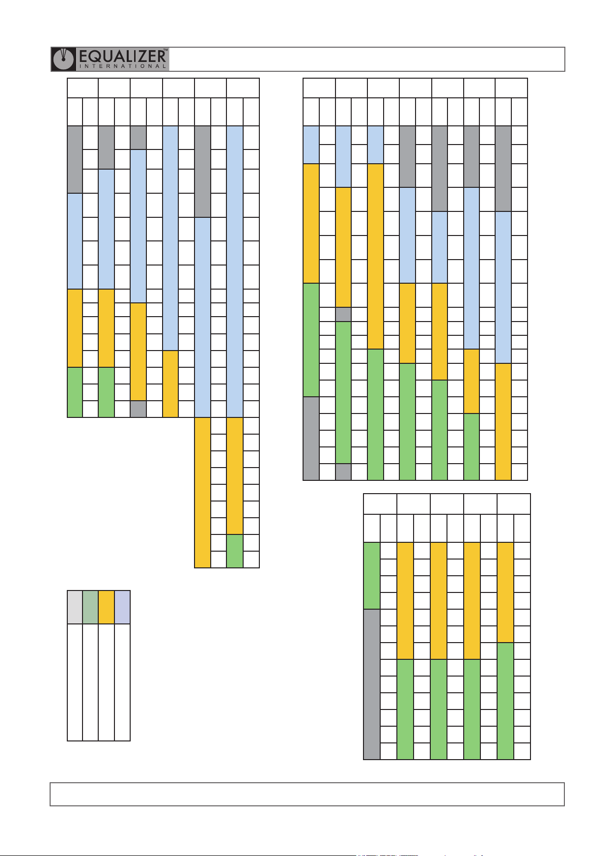
CLASS
PN160
TOOL FA1TM FA4TM FA9TE NOT SUITABLE FOR TOOLS
NPS 3/8" 1/2" 3/4" 1" 1 1/2" 2" 2 1/2" 3" 4" 5" 6" 7" 8" 10" 12" SUITABLE FOR FA9TE TOOL
CLASS
PN100
TOOL FA1TM FA4TM FA9TE SUITABLE FOR FA4TM TOOL
NPS 1/2" 3/4" 1" 1 1/2" 2" 2 1/2" 3" 4" 5" 6" 7" 8" 10" 12" 14" SUITABLE FOR FA1TM TOOL
CLASS
PN64
TOOL FA1TM FA4TM
NPS 3/4" 1" 1 1/2" 2" 2 1/2" 3" 4" 5" 6" 7" 8" 10" 12" 14" 16"
OPERATOR INSTRUCTION MANUAL
CLASS
PN40
TOOL FA1TM FA4TM
NPS 1 1/2" 2" 2 1/2" 3" 4" 5" 6" 7" 8" 10" 12" 14" 16" 18" 20"
CLASS
PN25
TOOL FA1TM FA4TM
NPS 1/2" 3/4" 1" 1 1/4" 1 1/2" 2" 2 1/2" 3" 4" 5" 6" 7" 8" 10" 12" 14" 16" 18" 20" 24" 28" 32" 36" 40"
CLASS
PN16
TOOL FA1TM FA4TM FA9TE
DIN WELD NECK FLANGE RANGE OF APPLICATION
NPS 1 1/2" 2" 2 1/2" 3" 4" 5" 6" 7" 8" 10" 12" 14" 16" 18" 20" 24" 28" 32" 36" 40" 48" 56" 72" 80"
CLASS
2500
TOOL FA1TM FA4TM FA9TE
NPS 1/2" 3/4" 1" 1 1/4" 1 1/2" 2" 2 1/2" 3" 4" 5" 6" 8" 10" 12" 14" 16"
CLASS
1500
TOOL FA1TM FA4TM FA9TE
NPS 1/2" 3/4" 1" 1 1/4" 1 1/2" 2" 2 1/2" 3" 4" 5" 6" 8" 10" 12" 14" 16"
CLASS
900
TOOL FA1TM FA4TM FA9TE
NPS 1/2" 3/4" 1" 1 1/4" 1 1/2" 2" 2 1/2" 3" 4" 5" 6" 8" 10" 12" 14" 16"
CLASS
600
TOOL FA1TM FA4TM FA9TE
NPS 3/4" 1" 1 1/4" 1 1/2" 2" 2 1/2" 3" 3 1/2" 4" 5" 6" 8" 10" 12" 14" 16"
CLASS
400
TOOL FA1TM FA4TM FA9TE
IM_FA1TM_Rev08_A4
300
NPS 3/4" 1" 1 1/4" 1 1/2" 2" 2 1/2" 3" 3 1/2" 4" 5" 6" 8" 10" 12" 14" 16"
CLASS
150
TOOL FA1TM FA4TM
NPS 3/4" 1" 1 1/4" 1 1/2" 2" 2 1/2" 3" 3 1/2" 4" 5" 6" 8" 10" 12" 14" 16"
NPS 3/4" 1" 1 1/4" 1 1/2" 2" 2 1/2" 3" 3 1/2" 4" 5" 6" 8" 10" 12" 14" 16"
CLASS
TOOL FA1TM FA4TM FA9TE
5.2 ASME B16.5 FLANGE RANGE OF APPLICATION
18" 20" 24"
18" 20" 24"
CLASS
900
TOOL FA9TE
NPS 22" 26" 28" 30" 32" 34" 36" 38" 40" 42" 44" 46" 48"
18" 20" 24"
CLASS
600
TOOL FA4TM FA9TE
NPS 22" 26" 28" 30" 32" 34" 36" 38" 40" 42" 44" 46" 48"
18" 20" 24"
CLASS
400
TOOL FA4TM FA9TE
NPS 22" 26" 28" 30" 32" 34" 36" 38" 40" 42" 44" 46" 48"
18" 20" 24"
CLASS
300
TOOL FA4TM FA9TE
18" 20" 24"
NPS 22" 26" 28" 30" 32" 34" 36" 38" 40" 42" 44" 46" 48"
CLASS
150
TOOL FA4TM FA9TE
18" 20" 24"
ASME B16.47 FLANGE RANGE OF APPLICATION
NPS 22" 26" 28" 30" 32" 34" 36" 38" 40" 42" 44" 46" 48"
FA1TM
11
FLANGE ALIGNMENT TOOL
Page 13
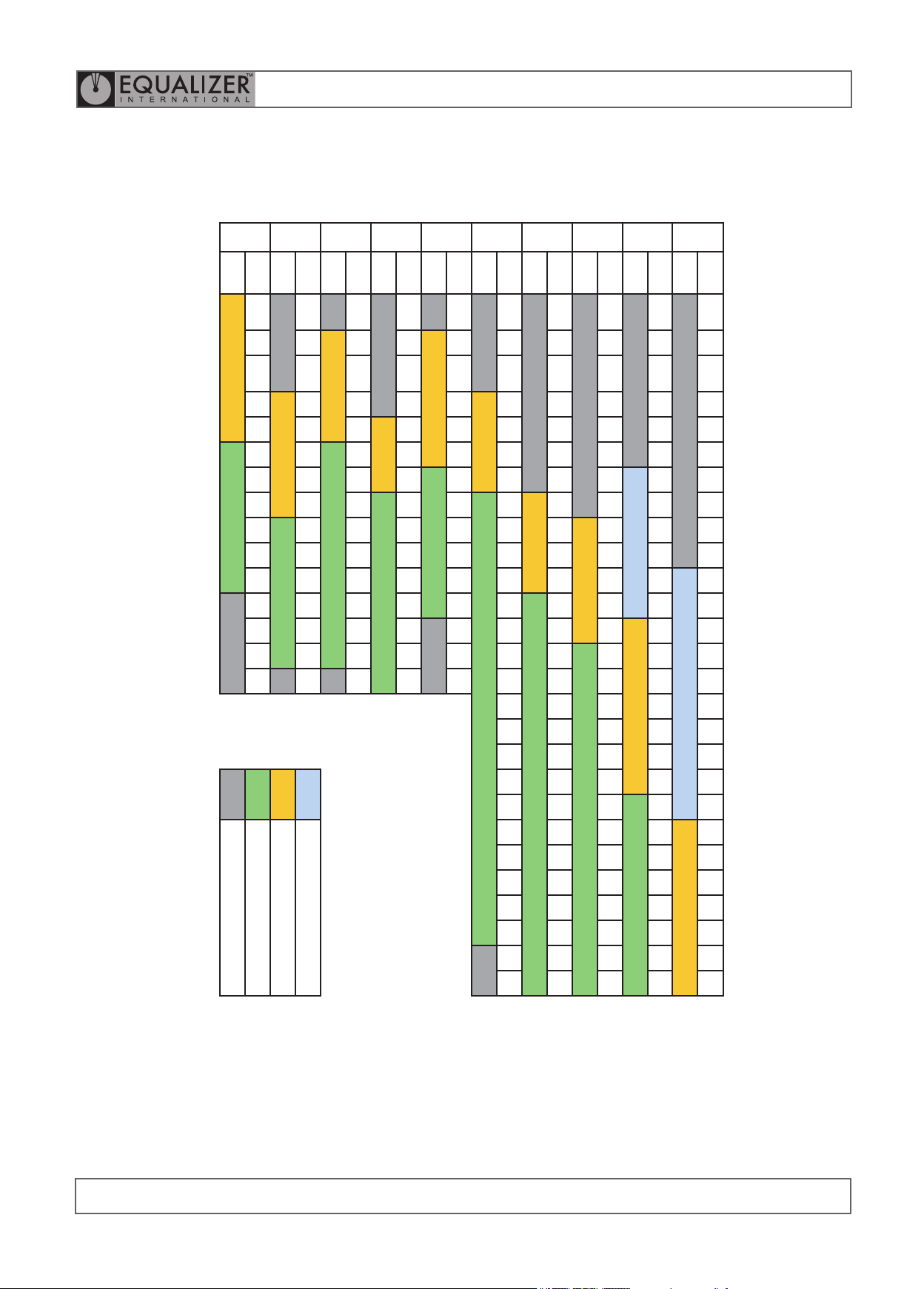
OPERATOR INSTRUCTION MANUAL
IM_FA1TM_Rev08_A4
CLASS
15000
TOOL FA4TM FA9TE NOT SUITABLE FOR TOOLS
NPS 2 1/2” 3” 3 1/2” 4” 5” 6” 8” 10” 12” 14” 16” 18” 20” 22” 24” SUITABLE FOR FA9TE TOOL
CLASS
10000
TOOL FA4TM FA9TE SUITABLE FOR FA4TM TOOL
NPS 2 1/2” 3” 3 1/2” 4” 5” 6” 8” 10” 12” 14” 16” 18” 20” 22” 24” SUITABLE FOR FA1TM TOOL
CLASS
7500
TOOL FA4TM FA9TE
NPS 2 1/2” 3” 3 1/2” 4” 5” 6” 8” 10” 12” 14” 16” 18” 20” 22” 24”
CLASS
5000
TOOL FA4TM FA9TE
NPS 2 1/2” 3” 3 1/2” 4” 5” 6” 8” 10” 12” 14” 16” 18” 20” 22” 24”
CLASS
2500
TOOL FA4TM FA9TE
NPS 2 1/2” 3” 3 1/2” 4” 5” 6” 8” 10” 12” 14” 16” 18” 20” 22” 24”
CLASS
1500
TOOL FA4TM FA9TE
NPS 2 1/2” 3” 3 1/2” 4” 5” 6” 8” 10” 12” 14” 16” 18” 20” 22” 24” 26” 28” 30” 32” 34” 36” 38” 40” 42” 44” 46” 48”
CLASS
900
TOOL FA4TM FA9TE
NPS 2 1/2” 3” 3 1/2” 4” 5” 6” 8” 10” 12” 14” 16” 18” 20” 22” 24” 26” 28” 30” 32” 34” 36” 38” 40” 42” 44” 46” 48”
CLASS
600
TOOL FA4TM FA9TE
NPS 2 1/2” 3” 3 1/2” 4” 5” 6” 8” 10” 12” 14” 16” 18” 20” 22” 24” 26” 28” 30” 32” 34” 36” 38” 40” 42” 44” 46” 48”
CLASS
300
TOOL FA1TM FA4TM FA9TE
NPS 2 1/2” 3” 3 1/2” 4” 5” 6” 8” 10” 12” 14” 16” 18” 20” 22” 24” 26” 28” 30” 32” 34” 36” 38” 40” 42” 44” 46” 48”
CLASS
150
TOOL FA1TM FA4TM
5.3 SPO FLANGE RANGE OF APPLICATION
NPS 2 1/2” 3” 3 1/2” 4” 5” 6” 8” 10” 12” 14” 16” 18” 20” 22” 24” 26” 28” 30” 32” 34” 36” 38” 40” 42” 44” 46” 48”
FA1TM
12
FLANGE ALIGNMENT TOOL
Page 14
OPERATOR INSTRUCTION MANUAL
6.
TROUBLESHOOTING
6.1
FA1TM TROUBLESHOOTING
THE TOOL IS ATTACHED AND APPEARS
TO BE FUNCTIONING PROPERLY, BUT
THE JOINT WILL NOT ALIGN
POSSIBLE CAUSE:
There may be something restricting the joint
from aligning.
IM_FA1TM_Rev08_A4
RECOMMENDED ACTION:
Check the area around the joint to establish if
there is an obstruction to the joint.
POSSIBLE CAUSE:
The joint may require more than 1 T (10 kN)
force to align.
RECOMMENDED ACTION:
If the joint requires more force than that of the
1 T (10 kN) tool, attach a second tool or another
method of aligning should be adapted.
FA1TM
13
FLANGE ALIGNMENT TOOL
Page 15
OPERATOR INSTRUCTION MANUAL
IM_FA1TM_Rev08_A4
7.
REGULATORY
INFORMATION
7.1
REGISTERED HEAD OFFICE
EQUALIZER INTERNATIONAL LTD.
Equalizer House
Claymore Drive
Aberdeen
Scotland
AB23 8GD
8.
PARTS LISTS
& SERVICE KITS
FA1TM
14
FLANGE ALIGNMENT TOOL
Page 16
OPERATOR INSTRUCTION MANUAL
This Parts List applies to tools with Serial Number 0382 or later.
For tools with Serial Number 0381 and prior, consult FA1TM_rev04 Manual
ITEM PART NO. DESCRIPTION QUANTITY
01
210200-01
02
210300-01
03
210400-01
04
210501-01
05
210500-01
06
210600-01
07
210800-01
08
210900-01
09
211100-01
10
211200-01
11
211300-01
12
211800-01
13
230203-01
14
211900-01
15
212000-01
16
210700-01
17
070280-01
18
070281-01
19
210100-01
20
211600-01
21
220800-01
BODY FRAME
DRIVEN WEDGE
DRIVE SCREW
BASE PLATE (3 mm)
COVER PLATE (2 mm)
CRANK HANDLE
TORSION SPRING
NEEDLE BEARING
BEARING SHAFT
SPRING MANDREL
M6 x 8 mm SOCKET FL. BT. SCREW
DROP LEG
M6 RELEASE KNOB
LEG PIN 8 mm
SPRING RING 8 mm
SPRING PIN 2 x 16 mm
BODY STICKER LEFT
BODY STICKER RIGHT
DRIVING WEDGE
SPACER SHIM
MINI RATCHET STRAP
01
01
01
01
01
01
01
04
04
01
12
01
01
01
02
01
01
01
01
01
01
IM_FA1TM_Rev08_A4
FA1TM
15
FLANGE ALIGNMENT TOOL
Page 17

Page 18

EQUALIZER INTERNATIONAL LTD.
Head Office
Equalizer House
Claymore Drive
Aberdeen
Scotland
UK
AB23 8GD
t: +44 (0) 1224 701970
f: +44 (0) 1224 823791
www.equalizerinternational.com
 Loading...