

Page 1

Radio temperature and
humidity sensor
ASH 2200US
Operating instructions
ELV Electronics Ltd. ● Hong Kong
1
Page 2

1st English edition January 2004
Documentation © 2004 ELV Electronics Limited
All rights reserved. This handbook must not be reproduced in any
form, even in excerpts, or duplicated or processed using electronic,
mechanical or chemical procedures without written permission of the
publisher.
This handbook may contain mistakes and printing errors. The information in this handbook is regularly checked and corrections made in
the next issue. We accept no liability for technical mistakes or printing
errors, or their consequences.
All trademarks and patents are acknowledged.
Printed in Hong Kong
Modifications due to technical improvements may be made without
prior notification.
00056979Y2004 V1.0
2
Page 3

Contents
1. General, functional features.......................... 4
Intended use ................................................. 4
2. Safety and maintenance information............ 5
3. Commissioning ............................................. 6
3.1. Inserting the batteries ................................... 6
3.2. Sensor addressing........................................ 7
3.3. Installation and dismounting......................... 8
4. Range and reception interference .............. 10
5. Changing the batteries ............................... 11
6. Technical data............................................. 11
7. FCC Information ......................................... 12
3
Page 4

1. General
The ASH 2200US radio climate sensors make it
possible to determine values for temperature and
humidity at the location of the sensor and to transmit
the data by radio to a reception station suitable for this
purpose, for example to the ELV BA 1010US. The
sensors can be flexibly mounted at different locations:
outdoors, in the green house, in the cellar, garage,
storage room and many other places. This
permits you to install a complete monitoring system
consisting of diverse locations.
Functional features:
ASH 2200US
- Freely addressable, battery operated, radio universal
temperature and humidity sensor for the temperature
range -30.0 ˚C to +70 ˚C and the humidity range 5 %
to 95 % relative humidity.
Please read these instructions fully and thoroughly
before initial commissioning; they contain information for the correct use of this device.
Intended use
The external sensing device ASH 2200US can be used
outdoors in a temperature range of -30 ˚C to +70 ˚C and
a maximum humidity of 95 %. Please observe the
instructions regarding the choice of installation location.
The manufacturer does not accept any liability for the
consequences of improper use; all rights under the
warranty will be forfeited.
4
Page 5

2. Safety and maintenance information
- The device has no user-serviceable parts.
- Avoid extreme moisture (e.g. it should not be directly
splashed with or immersed in water), direct sunlight,
and extremely dusty environments.
- Clean the display device and the external sensor
using a dry linen cloth, which may be slightly
dampened to remove obstinate soiling. Do not use
solvents for cleaning
- The device should be kept out of reach of children. It
is not a toy!
5
Page 6
3. Commissioning
3.1. Inserting the batteries
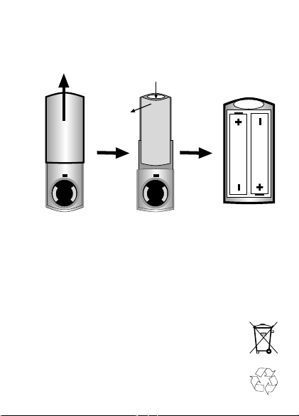
Remove the protective cap on the external sensor and
open the battery compartment as shown in the picture
below.
Insert two 1.5 V Mignon batteries (LR 6 / Mignon /
AA alkaline) into the battery compartment, ensuring that
the polarity is
correct (see illustration), and then close the battery
compartment.
Place the protective cap back on to the stop.
CAUTION! Observe regulations for the disposal of
batteries!
Used batteries and rechargeable accumulators
must not be thrown away with household
rubbish!
Please take exhausted batteries and rechargeables to your local dealer or to a collection point
for hazardous waste or batteries.
1
2
6
Page 7
3.2. Sensor addressing
Each sensor in the weather monitoring system is
assigned an address which enables the receiver to
integrate the sensor trouble-free into the system.
The factory setting for each sensor is address 1. Eight
addresses are available (1 to 8, corresponding to the
display).
You can carry out addressing yourself using the
jumpers on the sensor circuit board.
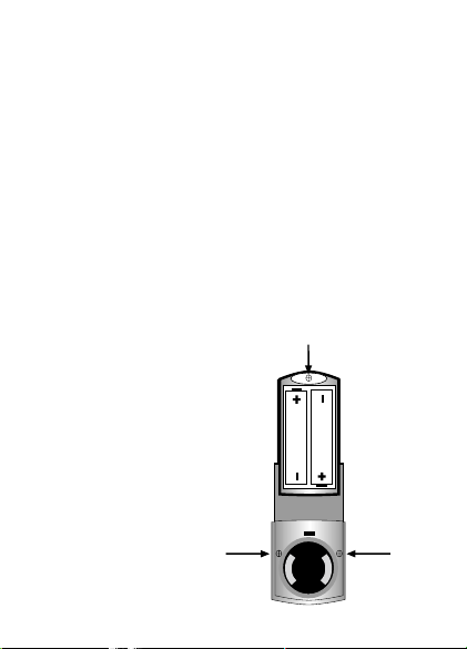
To do that, the protective cap must first be taken off of
the sensor housing and the batteries removed.
Y ou then remove the two scr ews on the back which are
on the left and right of the wall holder , remove the screw
above the battery compartment, and take off the front
half of the housing.
Undo
screw
Undo
screw
Undo
screw
7
Page 8
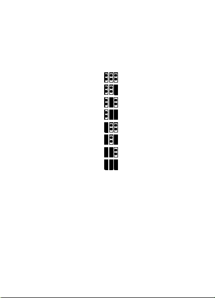
The jumpers can now be placed according to the
address table.
The black areas represent a jumper inserted at one of
the points (1, 2, 3).
Adresse
3 2 1
8
7
6
5
4
3
2
1
3.3. Installation and dismounting of the external
sensor
The external sensor can be very easily installed on a
vertical surface using the supplied mounting base.
CAUTION!
Choose an installation location that is not exposed to
direct precipitation, direct sunlight, or is extremely
dusty! Outdoor installation under a roof overhang, for
example, would be a suitable location.
8
Page 9

The mounting base is fastened onto a vertical surface
with a screw as shown in the following figure. Make sure
that the notch in the housing points up as in the drawing.
Notch points upward
Screw hole
Now the external sensor can be inserted vertically to the
stop in the mounting base.
If the external sensor needs to be dismounted (e.g. to
change batteries), it is pulled out to the front.
9
Page 10

4. Range and reception interference
The free field range (i.e. the range of the line of sight
contact between the transmitter and the receiver) is
100 m under optimum conditions. Walls and even
reinforced concrete can be penetrated, which does,
however, reduce the range.
In the event of interference, turn the display unit
slightly until it is again receiving data from the
required sensor.
A reduced range can have the following causes:
●
High frequency interference of all kinds
●
Buildings of all types or vegetation
●
The distance of the transmitter or receiver from
conductive surfaces or objects (even to the human
body or the ground) has an effect on the radiation
characteristics and therefore the range.
●
Wide band interference in built up areas can reach
levels that reduce the signal-noise ratio throughout
the frequency band which reduces the range.
●
Devices working on adjacent frequencies can also
affect the receiver.
●
Badly shielded PCs can radiate into the receiver and
reduce the range.
10
Page 11

5. Changing the batteries
The batteries in the sensors have a life of up to three
years (alkaline batteries). They must be changed when
the respective sensor does not appear in the display
unit and there is no general and long lasting interference of the radio path, which can usually be recognized
when there is no data transmission from other, neighbouring sensors either (see Section 4 “Range and reception interference”).
Batteries are changed as described in Section 3.1.
Following a battery change, the sensor is ready for
operation again after a test run in test mode (see
“Technical data”).
6. Technical data
Data transfer by radio: .............................433.92 MHz
Free field range: ................................................ 100 m
Data transfer cycle: ............................................3 min.
External temperature measurement range:
Temperature measurement resolution:............. 0.1 °C
Temperature measurement accuracy: ............ ±0.8 °C
Relative humidity measuring range:
Humidity measurement resolution: ....................0.1 %
Humidity measurement accuracy: ...................... ±5 %
Dimensions (Ø x H): ............................... 54 x 125 mm
Distance of external sensor to mounting surface:30 mm
Battery: ..............................2 x 1.5 V LR 6/Mignon/AA
-30.0 °C to +70.0 °C
5 % - 95 % rel. humidity
11
Page 12

7. FCC Information
FCC ID: RNT-ASH2200US
Changes or modifications not expressly approved in writing by
ELV Electronics Limited may void the user’s authority to operate
the equipment.
NOTE: This equipment has been tested and found to comply with
the limits for a Class B digital device, pursuant to Part 15 of the
FCC Rules. These limits are designed to provide reasonable
protection against harmful interference in a residential installation.
This equipment generates, uses and can radiate radio frequency
energy and, if not installed and used in accordance with the
instructions, may cause harmful interference to radio
communications. However, there is no guarantee that interference
will not occur in a particular installation. If this equipment does
cause harmful interference to radio or television reception, which
can be determined by turning the equipment off and on, the user
is encouraged to try to correct the interference by one or more of
the following measures:
- Reorient or relocate the receiving antenna.
- Increase the separation between the equipment and receiver.
- Connect the equipment into an outlet on a circuit different from
that to which the receiver is connected.
- Consult the dealer or an experienced radio/TV technician for
help.
The internal antenna used for this mobile transmitter must
provide a separation distance of at least 20 cm from all
persons and must not be co-located or operating in
conjunction with any other antenna or transmitter.
This device complies with Part 15 of the FCC Rules. Operation
is subject to the following two conditions:
(1) this device may not cause harmful interference,
and
(2) this device must accept any interference
received, including interference that may cause
undesired operation.
12
 Loading...