

Epygi Quadro M32x, Quadro M26xi, Quadro M8L, Quadro M26x, Quadro M12Li Installation Manual


QuadroM32x/8L/26x/12Li/26xi Manual I: Installation Guide
QuadroM32x/8L/26x/12Li/26xi; (SW Version 5.3.x)
Copyright and Trademarks
Copyright © 2003-2012 Epygi Technologies, Ltd. All Rights Reserved. Quadro is a registered trademark of Epygi Technologies, Ltd. Microsoft, Windows, and the Windows logo are registered trademarks of Microsoft Corporation. All other
trademarks and brand names are the property of their respective proprietors.
Limited Warranty
Epygi Technologies, Ltd. (‘Epygi’) warrants to the original end-user purchaser every Quadro to be free from physical defects in material and workmanship under normal use for a period of one (1) year from the date of purchase (proof of purchase required) or two (2) years from the date of purchase (proof of purchase required) for products purchased in the
European Union (EU). If Epygi receives notice of such defects, Epygi will, at its discretion, either repair or replace products that prove to be defective.
This warranty shall not apply to defects caused by (i) failure to follow Epygi’s installation, operation or maintenance instructions; (ii) external power sources such as a power line, telephone line, or connected equipm ent; (iii) products that
have been serviced or modified by a party other than Epygi or an authorized Epygi service center; (iv) products that have
had their original manufacturer’s serial numbers altered, defaced, or deleted; (v) damage due to lightning, fire, flood, or
other acts of God.
In no event shall Epygi’s liability exceed the price paid for the product from direct, indirect, special, incidental, or consequential damages resulting from the use of the product, its accompanying software, or its documentation. Epygi offers no
refunds for its products. Epygi makes no warranty or representation, expressed, implied, or statutory, with respect to its
products or the contents or use of this documentation and all accompanying software, and specifically disclaims its quality, performance, merchantability, or fitness for any particular purpose.
Return Policy
If the product proves to be defective during this warranty period, call Epygi Customer Support at (972) 692-1166 to obtain
a Return Material Authorization (RMA) Number. Registered users also may access Epygi’s Technical Support
(www.epygi.com; ‘Support’) to send their RMA request. For Brazil representatives, call (21) 2518-3161 or contact via Web
(www.saga.com.br). Please have your proof of purchase on hand when contacting us. When returning a product, mark
the Return Authorization Number clearly on the outside of the package and include your original proof of purchase. Return
requests cannot be processed without proof of purchase. Customers are responsible for shipping and handling charges
when shipping to Epygi.
Epygi or its service center will use commercially reasonable efforts to ship a replacement product within ten (10) working
days after receipt of the returned product. Actual delivery times may vary depending on customer location.
Epygi reserves the right to revise or update its products, pricing, software, or documentation without obligation to notify
any individual or entity. Please direct all inquiries to:
Epygi Technologies, Ltd., Two Legacy Town Center, 6900 North Dallas Parkway, Suite 850, Plano, Texas 75024
Representative in Brazil - Saga Sistemas e Computadores SA, Av. Rio Branco, 18 - 8 andar, Rio de Janeiro 20090-001
Notice to Users
This Installation Guide, in whole or in part, may not be reproduced, translated, or reduced to any machine-readable form
without prior written approval.
Epygi provides no warranty with regard to this Installation Guide or other information contained herein and hereby expressly disclaims any implied warranties of merchantability or fitness for any particula r pu rpo se in rega rd to this m anua l or
other such information. In no event shall Epygi be liable for any incidental, consequential, or special damages, whether
based on tort, contract, or otherwise, arising out of or in connection with this manual or other information contained herein
or the use thereof.
Administrative Council for Terminal Attachments (ACTA) Customer Information
This equipment complies with Part 68 of the FCC rules and the requirements adopted by the ACTA. On the back of this
equipment is a label that contains, among other information, a product identifier in the format US:AAAEQ###TXXXX,
made out to HX7OT00BHX70100. If requested, this number must be provided to the telephone company.
Any plug or jack that is used to connect this equipment to the premises wiring and telephone network must comply with
the applicable FCC Part 68 rules and requirements adopted by the ATCA.
The Ringer Equivalence Number is an indicator of the maximum number of devices allowed for connection to a telephone
interface. The termination on an interface may consist of any combination of devices subject only to the requirements that
the sum of the RENs of all the devices does not exceed five. Excessive RENs on a telephone line may result in the devices not ringing in response to an incoming line. The REN for this product is part of the product identifier that has the
format US:AAAEQ## #TXXX, m ade out to HX7OT00BHX70100. The digits represented by ### are the REN without a decimal point (in this case 00B is a REN of 0.0B.)
If the Quadro causes harm to the telephone network, the telephone com pany will notify you in advance that a tempora ry
discontinuance of service may be require d. But if ad vance notice isn’t p rac tical, th e tele phon e com pan y will notif y th e cu stomer as soon as possible. Also, you will be advised of your right to file a complaint with the FCC if you believe it is necessary.
The telephone company may make changes in its facilities, equipment, operations or procedures that could affect the operation of the equipment. If this happens, the telephone company will provide advance notice for you to make the necessary modifications to maintain uninterrupted service.
Connection to a party line service is subject to state tariffs. Contact the state public utility commission, public service
commission or the corporation commission for information.
If your home has specially wired alarm equipment connected to the telephone line, ensure the installation of the Quadro
does not disable your alarm equipment. If you have any questions about what will disable alarm equipment, consult your
telephone company or a qualified installer.

QuadroM32x/8L/26x/12Li/26xi Manual I: Installation Guide
QuadroM32x/8L/26x/12Li/26xi; (SW Version 5.3.x)
Electrical Safety Advisory
To reduce the risk of damaging power surges, we recommend you install an AC surge arrestor in the AC outlet from which
the Quadro is powered.
Industry Canada Statement
This product meets the applicable Industry Canada technical specifications.
Safety Information
Before using the Quadro, please review and ensure the following safety instructions are adhered to:
• To prevent fire or shock hazard, do not expose your Quadro to rain or moisture.
• To avoid electrical shock, do not open the Quadro. Refer servicing to qualified personnel only.
• Never install wiring during a lightning storm.
• Never install telephone jacks in wet locations unless the jack is specified for wet locations.
• Never touch uninsulated telephone wire or terminals unless the telephone line has been disconnected at the net-
work interface.
• Use caution when installing or modifying cable or telephone lines.
• Avoid using your Quadro during an electrical storm.
• Do not use your Quadro or telephone to report a gas leak in the vicinity of the leak.
• An electrical outlet should be as close as possible to the unit and easily accessible.
Emergency Services
The Quadro SIP Service is intended to function as a secondary telephone service. This service is made available through
the Internet and therefore is dependent upon a constant source of electricity and network availability. If a power outage
occurs, the Quadro SIP Service automatically will be disabled. User understands in the event of a power or network outage, the Quadro SIP Service will not support 911 emergency services, and further, such services only will be available via
the user's regular telephone line that is not connected to the Quadro. User further acknowledges that any interruption in
the supply or delivery of electricity or network availability is beyond Epygi's control and Epygi shall have no responsibility
for losses arising from such interruption.

QuadroM32x/8L/26x/12Li/26xi Manual I: Installation Guide
QuadroM32x/8L/26x/12Li/26xi; (SW Version 5.3.x)
Table of Contents
Manual I: Installation Guide
About This Installation Guide........................................................6
Requirements.............................................................................7
Hardware Overview.....................................................................8
The Connectors Panel of QuadroM32x/8L/26x/12Li/26xi.............................8
QuadroM32x/8L/26x/12Li/26xi’s Front Panel LEDs...................................12
Step 1: Installing the Quadro ..................................................... 14
Networking Overview...........................................................................14
LAN/WAN Connection Options ...............................................................15
Connecting the Hardware .....................................................................20
Step 2: Configuring the Quadro .................................................. 26
Step 2.1: Logging in to Quadro .............................................................27
Step 2.2: System Configuration Wizard..................................................28
System Configuration.....................................................................................28
DHCP Settings for the LAN Interface.................................................................29
Regional Settings...........................................................................................29
Emergency and PSTN Access Code Settings .......................................................30
Finishing the System Configuration Wizard ........................................................31
Step 2.3: Internet Configuration Wizard .................................................33
Uplink Configuration.......................................................................................34
WAN IP Configurat ion.....................................................................................35
PPP/PPTP Configuration...................................................................................36
WAN Interface Configuration ...........................................................................37
DNS Settings ................................................................................................37
Finishing the Internet Configuration Wizard........................................................38
Step 2-A: Using IP Lines............................................................39
Supported SIP Phones.......................................................................... 42
Tested SIP Phones...............................................................................42
Step 2-B: Using Receptionist...................................................... 44
Step 2-C: Using ISDN Lines........................................................ 45
Step 2-D: Configuring the E1/T1 Settings ..................................... 51
Editing the E1/T1 Trunk..................................................................................52
Signaling Type CCS........................................................................................53
Signaling Type CAS........................................................................................59
Step 3: Registering on Epygi’s Technical Support...........................66
Appendix: Changing the Admin Password.....................................67
Appendix: Configuring NAT Traversal........................................... 69
Appendix: Registering on Epygi’s SIP Server................................. 71
Appendix: Checking the Connections ........................................... 75

QuadroM32x/8L/26x/12Li/26xi Manual I: Installation Guide
Appendix: Pin Assignment of ISDN..............................................77
Appendix: Pin Assignment of E1/T1.............................................78
Manual II: see Administrator's Guide
This guide describes in detail the menus available for administrators only. Furthermore, it includes all the system’s default values at a glance.
Manual III: see Extension User's Guide
This guide describes in detail the menus av ailable for extension users. F urthermore, it includes all the call codes at a glance.
QuadroM32x/8L/26x/12Li/26xi; (SW Version 5.3.x)

QuadroM32x/8L/26x/12Li/26xi Manual I: Installation Guide About This Installation Guide
About This Installation Guide
This Installation Guide explains the installation of the QuadroM IP PBX. It gives step-bystep instructions to provision the QuadroM and configure the phone extensions. After successfully configuring the Quadro, a user will be able to make SIP and local PBX calls, as
well as calls to the PSTN and access the Internet from devices connected to the LAN.
• QuadroM8L offers 8 phone line (FXO), 2 phone extensions (FXS), 1 Ethernet WAN
port and 1 Ehernet LAN port
• QuadroM26x offers 8 phone line (FXO), 26 phone extensions (FXS), 1 Ethernet WAN
port and 1 Ehernet LAN port
• QuadroM12Li supports 6 phone line (ISDN), 2 phone extensions (FXS), 1 Ethernet
WAN port and 1 Ethernet LAN port
• QuadroM26xi supports 6 phone line (ISDN), 26 phone extensions (FXS), 1 Ethernet
WAN port and 1 Ethernet LAN port
• QuadroM32x offers one phone line (E1/T1), 2 phone extensions (FXS), 1 Ehernet
WAN port, 1 Ethernet LAN port and 1 ETH port.
This Installation Guide does not provide advanced configuration information. For these features, refer to the Administrator's and Extension User's Guides.
Step 1: Installing the Quadro
explains the connection of cables and devices to the Qua-
dro.
Step 2: Configuring the Quadro
describes the configuration steps necessary to integrate
the Quadro into your network environment.
Step 2-A: Using IP Lines
explains how to configure IP lines on the QuadroM IP PBX and
to connect IP phones.
Step 2-B: Using Receptionist
refers to the document describing Receptionist’s configura-
tion on the Quadro.
Step 2-C: Using ISDN Lines
explains how to configure ISDN trunks and to define a de-
fault outgoing MSN.
Step 2-D: Configuring the E1/T1 Settings
describes the basic E1/T1 settings.
Step 3: Registering on Epygi’s Technical Support
shows you how to access the Epygi
Technical Support Center and the Epygi SIP Server.
Appendix: Changing the Admin Password
explains how to change the default administra-
tor password.
Appendix: Configuring NAT Traversal
explains configuration of the Quadro if it is placed
behind a NAT enabled router.
Appendix: Registering on Epygi’s SIP Server
explains how to register on Epygi's powerful
SIP server.
Appendix: Checking the Connections
gives hints on solving common problems.
QuadroM32x/8L/26x/12Li/26xi; (SW Version 5.3.x) 6

QuadroM32x/8L/26x/12Li/26xi Manual I: Installation Guide Requirements
Requirements
• One 120/240 VAC power outlet in close proximity to the Quadro.
• One RJ45 Ethernet 10/100 broadband Internet connection.
• For QuadroM32x one E1/T1 cable to connect the Quadro with the CO or PBX.
• At least one off-the-shelf analog phone with an RJ11 telephone cable.
• For QuadroM26x/26xi RJ21 connector (F) with cable and distributed panel.
• At least one IP phone with CAT5 cable with RJ45 connector.
• One CAT 5 Ethernet cable with RJ45 connector to connect to the Quadro’s LAN port.
• One PC with a 10/100 Mbps Ethernet card or adapter installed.
• TCP/IP network protocol installed on each PC.
• Internet Explorer, Netscape Navigator, Mozilla Firefox or Opera browser is recom-
mended.
Please Note: The QuadroM32x/8L/26x IP PBX is shipped with one RJ11 cable and one
straight RJ45 CAT 5 cable. The QuadroM12Li/26xi IP PBX is shipped with one straight
RJ45 CAT 5 cable. If the LAN connector of the Quadro conn ects to a hub or switch, a crossover cable may be required.
Other cables are added according to the different connectivity requirements of the
QuadroM IP PBX types.
QuadroM32x/8L/26x/12Li/26xi; (SW Version 5.3.x) 7
QuadroM32x/8L/26x/12Li/26xi Manual I: Installation Guide Hardware Overview
Hardware Overview
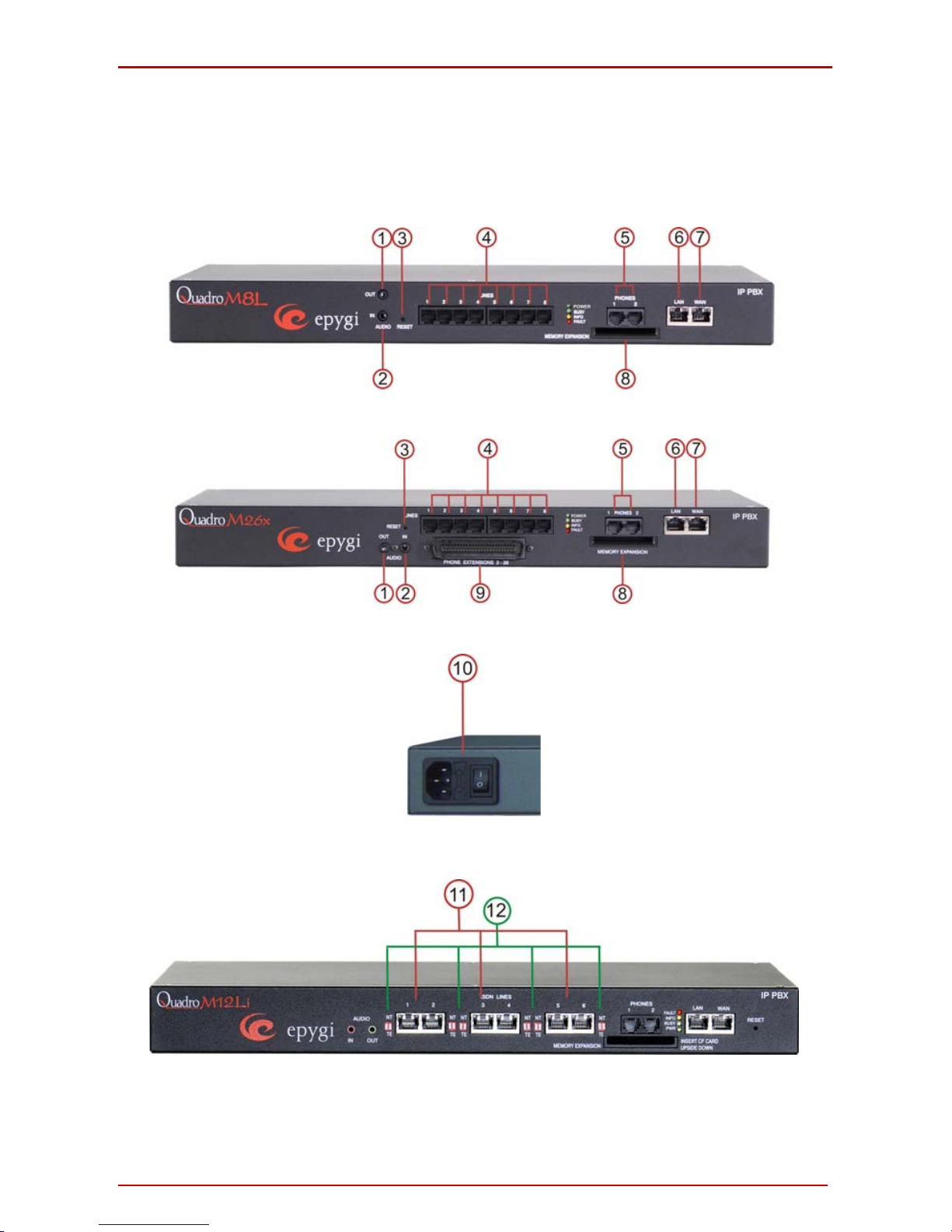
The Connectors Panel of QuadroM32x/8L/26x/12Li/26xi
The illustration below includes the connector’s panel of QuadroM.
Fig. I-1: QuadroM8L’s Connectors Panel
Fig. I-2: QuadroM26x's Connectors Panel
Fig. I-3: QuadroM Back Power Panel
Fig. I-4: QuadroM12Li's Connectors Panel
QuadroM32x/8L/26x/12Li/26xi; (SW Version 5.3.x) 8
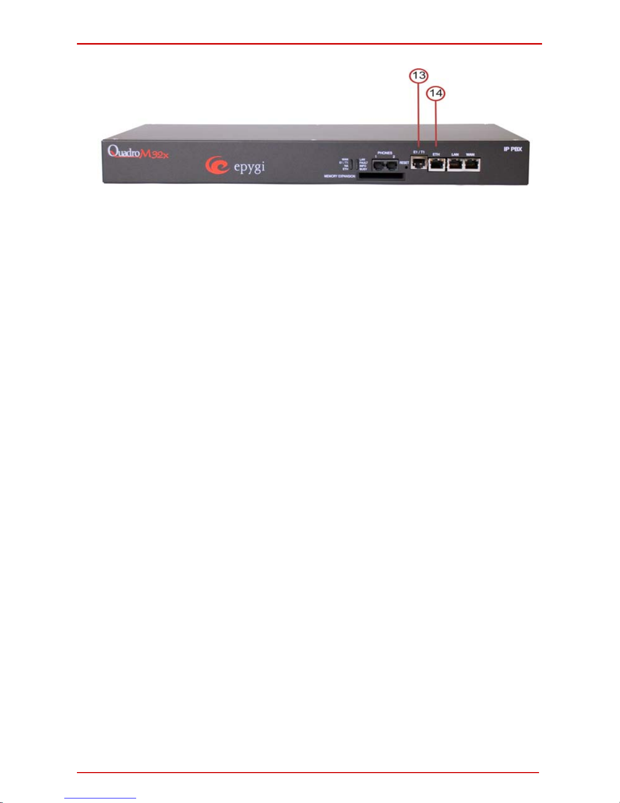
QuadroM32x/8L/26x/12Li/26xi Manual I: Installation Guide Hardware Overview
Fig. I-5: QuadroM32x's Connectors Panel
1 For QuadroM8L/26x/12Li/26xi AUDIO IN connector connects Quad ro to the radio or
any other audio resource to be used for the hold music.
2 For QuadroM8L/26x/12Li/26xi AUDIO OUT connector is used for Paging service. The
Paging Group service is used to page a group of extensions by forcing extensions to
go off-hook and opening one-way communication. The service is particularly used for
announcements addressed to a group of extensions. Service allows to page multiple
extensions by dialing the Paging Group extension.
Please Note: The Paging Group service requires called extensions to use one of the fol-
lowing SIP or analog phones which are able to automatically go off-hook:
• snom 190 • Grandstream GXP1450
• snom 200 • Grandstream GXP2000
• snom 220 • Grandstream GXP2100
• snom 300 • Grandstream GXP2110
• snom 320 • Grandstream GXP2120
• snom 360 • Grandstream GXV3140
• snom 370 • Grandstream GXV3175
• snom 820 • Polycom SoundPoint IP 300SIP
• snom 870 • Polycom SoundPoint IP 330SIP
• snom MeetingPoint • Polycom SoundPoint IP 331SIP
• Aastra 480i • Polycom SoundPoint IP 335SIP
• Aastra 480iCT • Polycom SoundPoint IP 450SIP
• Aastra 9112i • Polycom SoundPoint IP 501SIP
• Aastra 9133i • Polycom SoundPoint IP 550SIP
• Aastra 9143i(33i) • Polycom SoundPoint IP 601SIP
• Aastra 9480i(35i) • Polycom SoundPoint IP 650SIP
• Aastra 9480iCT • Polycom SoundStation IP 6000
• Aastra 6751i • Polycom VVX 1500
• Aastra 6753i • Linksys SPA921
• Aastra 6755i • Linksys SPA922
• Aastra 6757i • Linksys SPA941
• Aastra 6757iCT • Linksys SPA942
QuadroM32x/8L/26x/12Li/26xi; (SW Version 5.3.x) 9

QuadroM32x/8L/26x/12Li/26xi Manual I: Installation Guide Hardware Overview
• Aastra 6730i • Linksys SPA2002
• Aastra 6731i • Linksys SPAPAP2T
• Aastra 6739i • Yealink SIP-T20P
• Aastra 480e (analog phone) • Yealink SIP-T22P
• Thomson ST2030S • Yealink SIP-T26P
• Grandstream BT200 • Yealink SIP-T28P
• Grandstream GXP1400 • AudioCodes 310HD
• Grandstream GXP1405 • AudioCodes 320HD
Attention: Call paging will not work if the called extension is in call.
3 The Reset button may be used in two ways: (1) to initiate a normal reset or (2) to
carry out a factory reset. A normal reset is executed by pressing the Reset button
with a paper clip for an instant. Pressing the reset button and holding it down for
seven seconds or more will execute a factory reset. This will restore the factory defaults and clear all settings including the IP address and the administration password
you entered.
Please Note: A Factory Reset forces the default LAN IP address of 172.30.0.1 and default
admin password of 19.
4 LINE sockets to connect the Quadro to the PSTN network using standard analog
phone service. These are FXO (Foreign Exchange Office) analog ports.
5 PHONE sockets with RJ11 connectors enable connectivity of regular analog tele-
phones. These are FXS (Foreign Exchange Station) analog ports.
Attention: PHONE socket 1 must be connected to a telephone LINE 8 to enable lifeline
support functionality.
6 LAN RJ45 socket to attach to the IP phones in the Quadro’s Local Area Network
(LAN) via an Ethernet CAT 5 cable. For connecting multiple IP phones, a switch is
used.
7 WAN RJ45 socket to attach the Internet Uplink (WAN) via an Ethernet CAT 5 cable.
8 The CF socket enables connectivity of Compact Flash memory providing expansion
for additional voice mails and record data.
Attention: Power down the Quadro before inserting/removing the Compact Flash memory
card.
9 The TELCO (50-pin connector) socket with RJ-21 M connector enables up to 24 addi-
tional analog LINEs (3-26) support. This is an FXS analog ports expansion.
10 Power supply socket to connect a power cable.
11 ISDN sockets to connect the Quadro to the ISDN network termination units to use
PSTN services. A straight Ethernet CAT 5 cable can be used with an RJ45 connector
according to the ISDN Pin assignment, see Appendix: Pin Assignment of ISDN
.
12 The NT/TE switches are used to control the QuadroM12Li/26xi device on the S/T
Bus. If the QuadroM12Li/26xi is connected to the beginning or end of the S/T Bus or
if there is only one ISDN unit connected to the S/T Bus, then this switch should be
QuadroM32x/8L/26x/12Li/26xi; (SW Version 5.3.x) 10

QuadroM32x/8L/26x/12Li/26xi Manual I: Installation Guide Hardware Overview
toggled to the NT (Network Terminator) position. Otherwise, if the QuadroM12Li/26xi
is connected in the middle of the S/T Bus, the switch should be toggled to the TE
(Terminal Endpoint) position.
S/T Bus is a full-duplex interface. It consists of two groups (one for transmit and the
other one for receive) of two-wire interface and might support multiple devices (up to
8 devices can be attached to the S/T Bus). Both ends of each of the two-wire int erfaces should be terminated (100ohm resistance is present at both ends of each twowire interface).
Please Note: If the trunks on the QuadroM12Li/26xi have incorrect NT/TE position, they
may not function properly, including connection establishment permanent failure.
13 RJ-45 socket to attach the E1/T1 trunk. See Appendix: Pin Assignment of E1/T1
.
14 ETH RJ45 socket to attach the PC in the Quadro’s Local Area Network (LAN). If a
PC is connected directly to this socket, a straight Ethernet CAT 5 cable is used.
QuadroM32x/8L/26x/12Li/26xi; (SW Version 5.3.x) 11
QuadroM32x/8L/26x/12Li/26xi Manual I: Installation Guide Hardware Overview
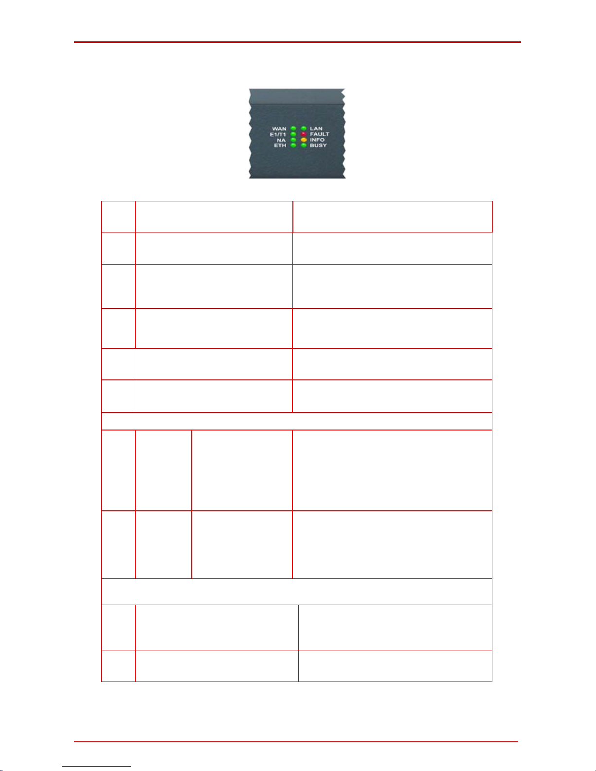
QuadroM32x/8L/26x/12Li/26xi’s Front Panel LEDs
Fig. I-6: QuadroM32x's Front Panel LEDs
1.
POWER
green
Status of the Power Supply
on: power supply ok
off: no power supply or device is still booting
2.
Busy
green
Status of CPU
off: no power
on or blinking: normal activity
3.
Info
yellow
System information
on: device is booting
off: no information
blinking: an event occurred; details specified in the
Sys tem Event section of the Management interface
4.
Fault
red
System status
on either an error or the device is booting
off: no error
blinking: system unusable
5.
WAN
green
Status of the WAN interface
on: link ok
off: no link
flickering: traffic on the link
6.
LAN
green
Status of the LAN interface
on: link ok
off: no link
flickering: traffic on the link
QuadroM12Li/26xi’s Additional Front Panel LEDs
7.
Green LED
for ISDN
Trunks 1-6
ISDN Link Status
on: ISDN link is UP, Frame Synchronization is OK
off: - In passive mode ISDN link status is not
informative.
- In non passive mode ISDN link is not con-
nected or ISDN trunks are stopped from GUI
8.
Orange LED
for ISDN
Trunks 1-6
Power Source Status on
ISDN Network Mode
on: Power Source checkbox is selected from GUI on
Network Mode and some type of ISDN devices(ISDN Phones, etc.) can receive power from
Quadro
off: Power Source checkbox is not selected from GUI
QuadroM32x’s Additional Front Panel LEDs
9.
ETH
green
Status of the ETH interface
on: link ok
off: no link
flickering: traffic on the link
10.
E1/T1
green
Status of the E1/T1 trunk
on: frame synchronization is ok
off: frame synchronization is not ok or link is down
QuadroM32x/8L/26x/12Li/26xi; (SW Version 5.3.x) 12

QuadroM32x/8L/26x/12Li/26xi Manual I: Installation Guide Hardware Overview
LED indication during a firmware update
A firmware update is indicated by the red (Fault) and yellow (Info) LEDs. Both will blink simultaneously for about two minutes while the firmware is being updated. The Quadro will
then reboot automatically showing the boot LED sequence.
LED indication during a boot sequence
A boot sequence is indicated as follows: The red Fault LED will glow for a few seconds,
then the yellow Info LED will glow for another four or five minutes while the green Busy
LED is blinking. Once the Info LED is off, the boot sequence has been completed successfully.
LED indication during emergency firmware upload
The red Fault LED and the yellow Busy LEDs will stop blinking alternately and start blinking in parallel. This shows that Quadro has accepted the emergency firmware and is loading it. After a few seconds, Quadro will boot, indicated as follows: The red Fault LED will
glow for a few seconds, then the yellow Info LED will glow for another few seconds while
the green Busy LED is jittering. When the yellow Info LED extinguishes, the boot sequence has been completed successfully.
QuadroM32x/8L/26x/12Li/26xi; (SW Version 5.3.x) 13

QuadroM32x/8L/26x/12Li/26xi Manual I: Installation Guide Step 1: Installing the Quadro
Step 1: Installing the Quadro
Networking Overview
To establish a connection between the Internet and your local area net work (LAN), an access router is needed. The QuadroM IP PBX can serve, among other functions, as an access router and will perform the task of connecting your LAN, or a group of one or more
PCs, to the wide area network (WAN) or the Internet. The Quadro will process and regulate
the data traffic between these two networks.
The Quadro is a device with two sides: one side connects to your LAN, and the ot her side
connects to the Internet, or to the WAN. Quadro’s firewall and Network Address Translation
(NAT) functionality protects your LAN from being seen from the Internet side making the
LAN private and secure.
Both Ethernet WAN and LAN ports transmit up to 100 Mbps traffic.
Every device within an IP network requires a unique IP address to identify itself. Since the
Quadro connects to both the LAN and the WAN, it has to be part of both networks, and
must have two IP addresses: one for the WAN side and one for the LAN side. The Quadro’s integrated firewall/NAT functionality will hide the LAN IP address from the WAN (Internet) side.
There are two ways of assigning an IP address: statically or dynamically.
A Static IP address is a fixed, manually assigned IP address that remains valid until
changed. If you plan to use the Quadro as your Internet access router, contact your Internet
Service Provider (ISP) to find out if a static IP address is assigned to your account. If so,
you will need this static IP address when configuring the Quadro device.
A dynamic IP address is a temporary address that is automatically assigned by your ISP
and will change periodically. If your ISP offers a dynamic IP address, the Quadro will act as
a DHCP client and will receive a new IP address from the ISP’s DHCP server or PPPoE
feature.
Please Note: A DHCP client is a piece of software that requests an IP address from a
DHCP server. A DHCP server assigns on request a unique IP address to a device. The
Quadro, like many routers, acts as a DHCP client on its WAN interface and as a DHCP
server on its LAN interface.
The Quadro must be visible to the Internet to be able to receive and send VoIP calls. When
the Quadro is placed in a private network, typically behind existing routers, it will by default
attempt to pass through the NAT of this router with its STUN (Simple Traversal of UDP over
NAT) feature. STUN will work without user configuration with the majority of basic routers.
In some scenarios, port forwarding on the router is required to make the Quadro accessible
to other Quadro devices and the Epygi SIP Server on the Internet. Another configuration
option is to use the Quadro as the Internet access router, connected directl y to the WAN,
eliminating the traverse to the local NAT firewall.
QuadroM32x/8L/26x/12Li/26xi; (SW Version 5.3.x) 14

QuadroM32x/8L/26x/12Li/26xi Manual I: Installation Guide Step 1: Installing the Quadro
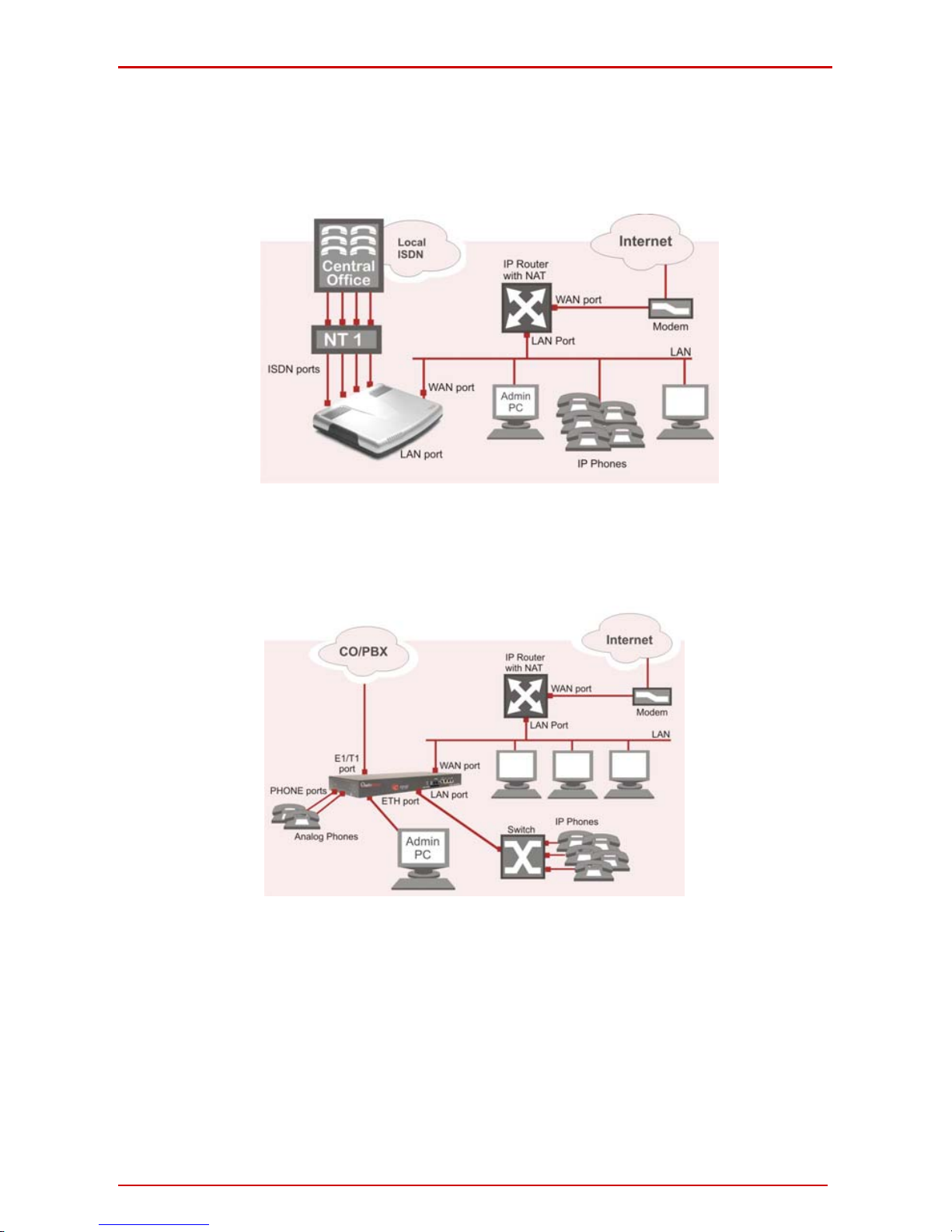
LAN/WAN Connection Options
• A QuadroM32x IP PBX with an Ethernet WAN port behind a router, w hich is con-
nected to a cable or xDSL modem. IP phones are placed on the W AN side of the
QuadroM32x.
Fig. I-7: Configuration: QuadroM32x behind a router with IP phones on WAN
• A QuadroM8L/26x IP PBX with an Ethernet WAN port behi nd a router, which is
connected to a cable or xDSL modem. IP phones are pla ced on the WAN side of
the QuadroM8L/26x.
Fig. I-8: Configuration: QuadroM8L/26x behind a router with IP phones on WAN
In this and the following configuration, the IP router typically acts as a DHCP server for the
LAN and assigns the IP addresses to the PCs and other devices. The Quadro can be connected through its WAN port directly to one of the router's LAN ports and will get an IP address from the router. By default, the Quadro acts as a DHCP client on the WAN port. The
IP phones are placed on the WAN side of the QuadroM8L/26x, connected to th e company
LAN.
The Admin PC can be connected to the Quadro LAN or WAN port to access the Web Management of the Quadro.
Please note: Since Quadro uses STUN by default, it will work with most basic routers
without any further configuration.
QuadroM32x/8L/26x/12Li/26xi; (SW Version 5.3.x) 15
QuadroM32x/8L/26x/12Li/26xi Manual I: Installation Guide Step 1: Installing the Quadro
• A QuadroM12Li/26xi with an Ethernet WAN port behi nd a router, which is
connected to a cable or xDSL modem. IP phones ar e placed on the WAN
side of the QuadroM12Li/26xi.
Fig. I-9: Configuration: QuadroM12Li/26xi behind a router with IP phones on WAN
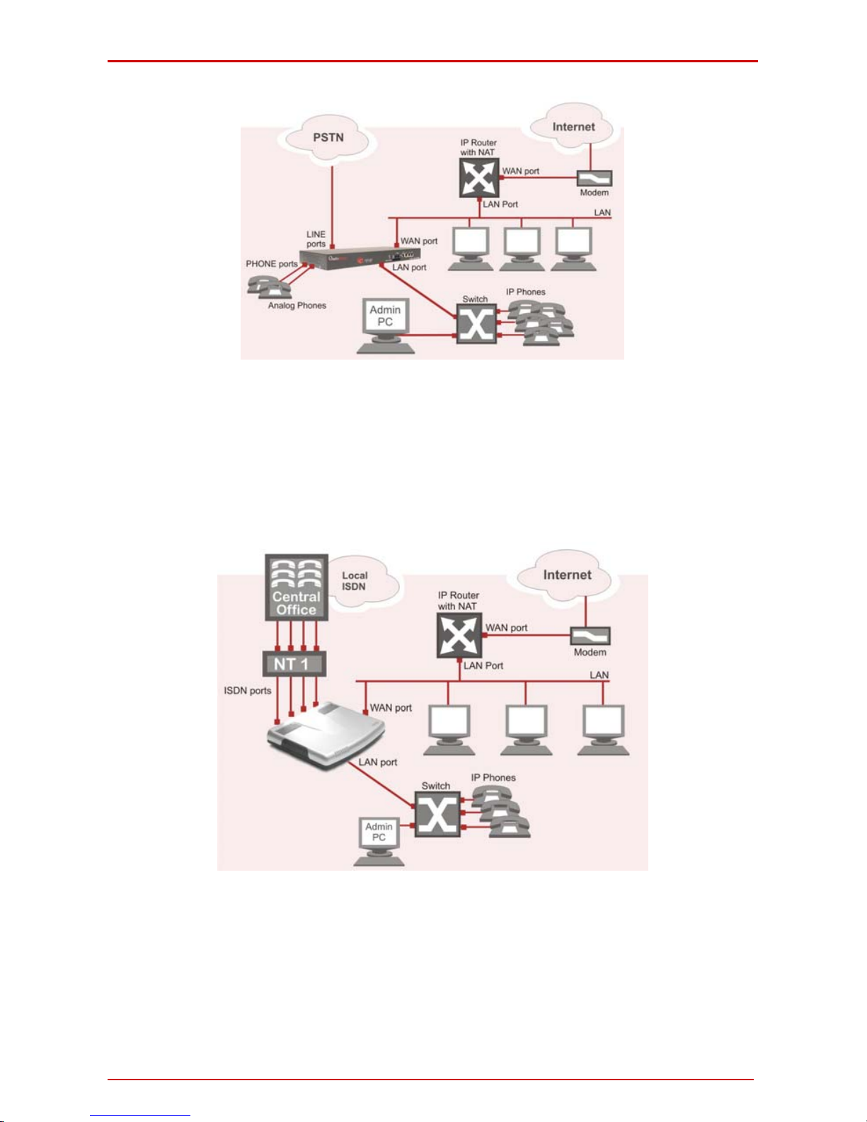
• A QuadroM32x IP PBX with an Ethernet WAN port behind a router, which is con-
nected to a cable or xDSL modem. IP phones are placed on the LAN side of the
QuadroM32x.
Fig. I-10: Configuration: QuadroM32x behind a router with IP phones on LAN
• A QuadroM8L/26x IP PBX with an Ethernet WAN port behind a router, which is
connected to a cable or xDSL modem. IP pho nes are placed on the LAN side of
the QuadroM8L/26x.
QuadroM32x/8L/26x/12Li/26xi; (SW Version 5.3.x) 16
QuadroM32x/8L/26x/12Li/26xi Manual I: Installation Guide Step 1: Installing the Quadro
Fig. I-11: Configuration: QuadroM8L/26x behind a router with IP phones on LAN
This configuration is identical to the previous configuration, with the difference that IP
phones are connected to the LAN port of the QuadroM. The QuadroM can be configured as
a DHCP server to provide the network parameters to the devices on its LAN.
• A QuadroM12Li/26xi with an Ethernet WAN port behi nd a router, which is con-
nected to a cable or xDSL modem. IP phones are placed on the L AN side of the
QuadroM12Li/26xi.
Fig. I-12: Configuration: QuadroM12Li/26xi behind a router with IP phones on LAN
QuadroM32x/8L/26x/12Li/26xi; (SW Version 5.3.x) 17
QuadroM32x/8L/26x/12Li/26xi Manual I: Installation Guide Step 1: Installing the Quadro
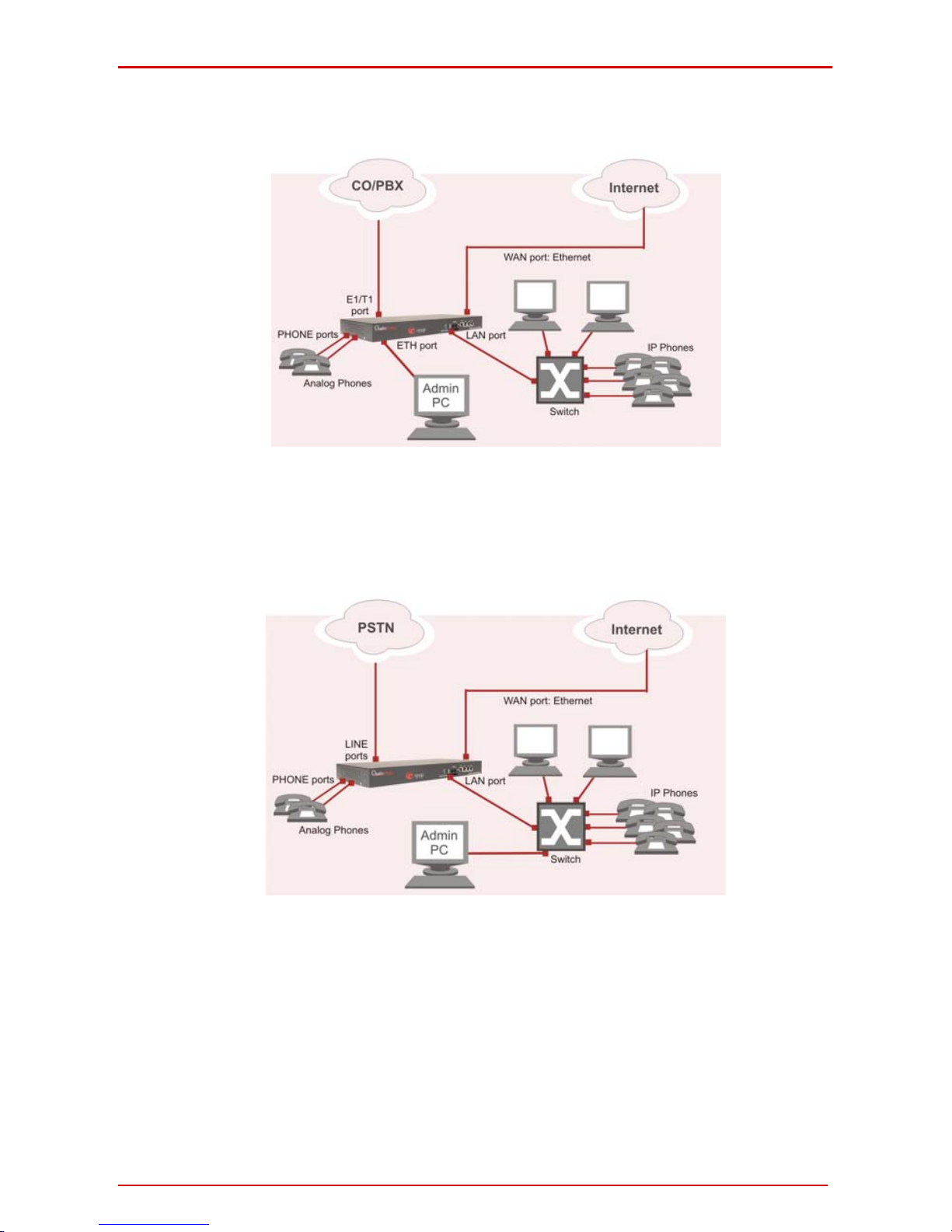
• A QuadroM32x IP PBX used as an Internet Access Router, connected di-
rectly to the Internet.
Fig. I-13: Configuration: QuadroM32x used as Internet Access Router
The Admin PC is connected to the Quadro ETH port or WAN port to access the Web Management of the Quadro.
• A QuadroM8L/26x IP PBX used as an Internet Access Router, connected di-
rectly to the Internet.
Fig. I-14: Configuration: QuadroM8L/26x used as Internet Access Router
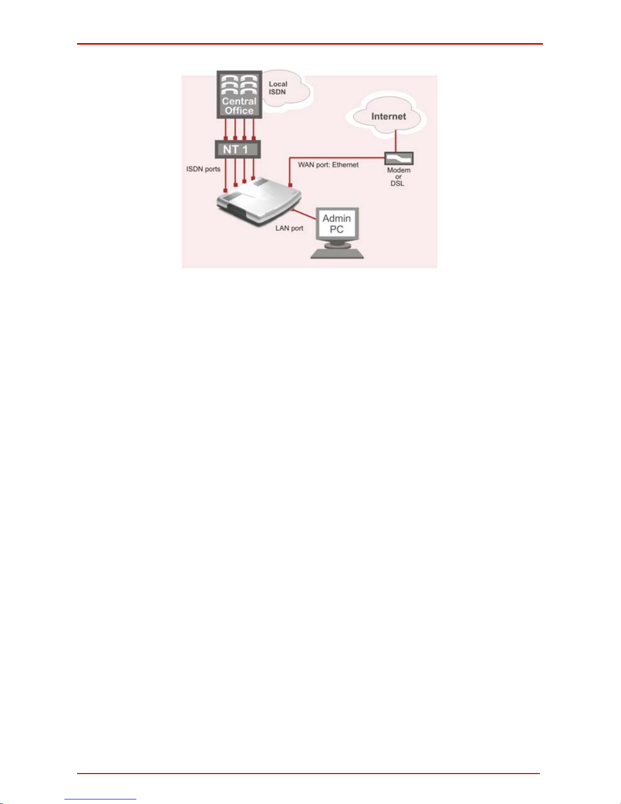
• A QuadroM12Li/26xi used as an Internet Access Router, connected directly
to the Internet.
QuadroM32x/8L/26x/12Li/26xi; (SW Version 5.3.x) 18
QuadroM32x/8L/26x/12Li/26xi Manual I: Installation Guide Step 1: Installing the Quadro
Fig. I-15: Configuration: QuadroM12Li/26xi used as Internet Access Router
Please Note: The Admin PC is connected to the Quadro’s LAN p ort through a switch/hub
to access the Web Management of the QuadroM. It is recommended to have Admin PC
acting as a DHCP client and obtaining IP address from the Quadro.
QuadroM32x/8L/26x/12Li/26xi; (SW Version 5.3.x) 19
QuadroM32x/8L/26x/12Li/26xi Manual I: Installation Guide Connecting the Hardware
Connecting the Hardware
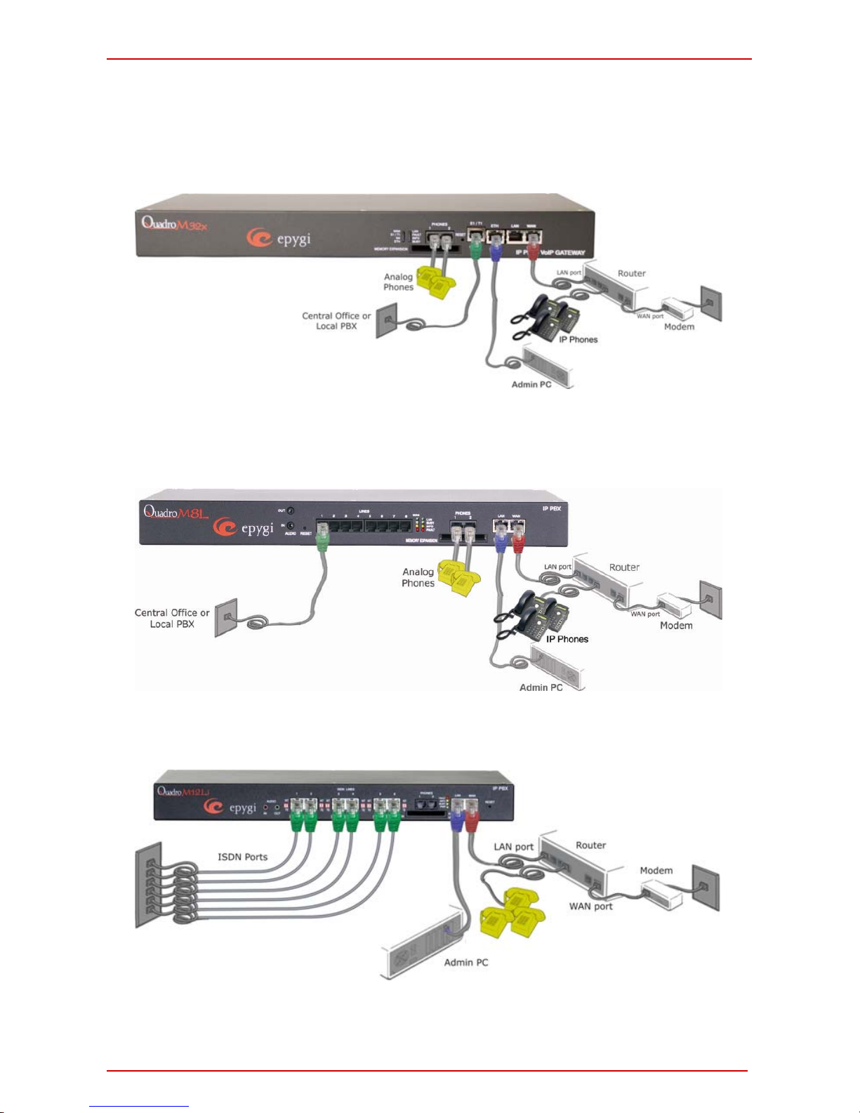
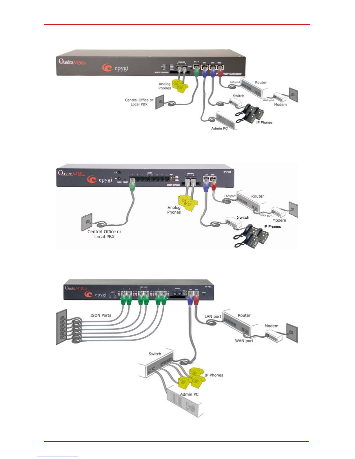
• QuadroM32x behind a router with IP phones connected to WAN
Fig. I-16: Installation: QuadroM32x behind a router with IP phones on WAN
• QuadroM8L/26x behind a router with IP phones connected to WAN
Fig. I-17: Installation: QuadroM8L/26x behind a router with IP phones on WAN
• QuadroM12Li/26xi behind a router with IP phones connected to WAN
Fig. I-18: Installation: QuadroM12Li/26xi behind a router with IP phones on WAN
QuadroM32x/8L/26x/12Li/26xi; (SW Version 5.3.x) 20
QuadroM32x/8L/26x/12Li/26xi Manual I: Installation Guide Connecting the Hardware
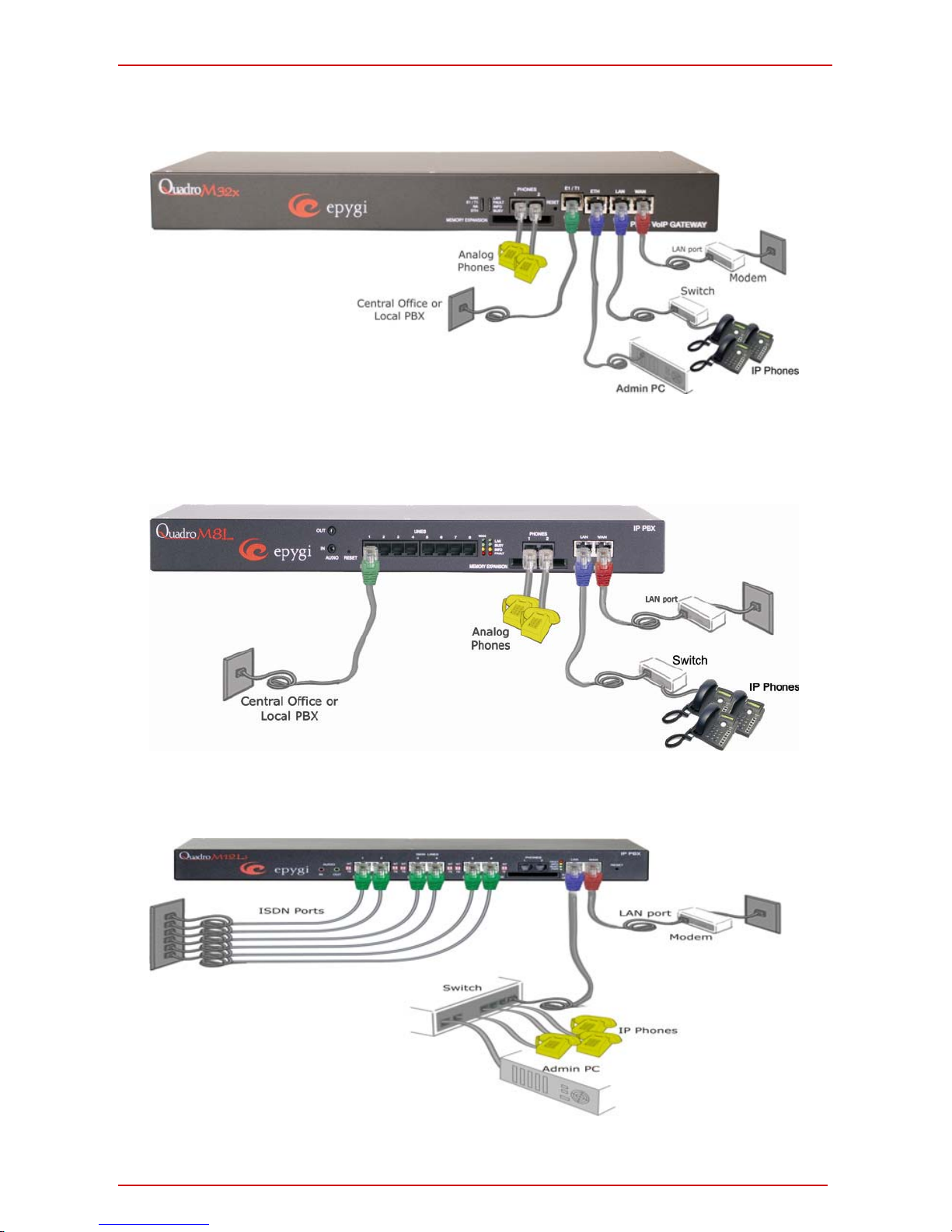
• QuadroM32x behind a router with IP phones connected to LAN
Fig. I-19: Installation: QuadroM32x behind a router with IP phones on LAN
• QuadroM8L/26x behind a router with IP phones connected to LAN
Fig. I-20: Installation: QuadroM8L/26x behind a router with IP phones on LAN
• QuadroM12Li/26xi behind a router with IP phones connected to LAN
Fig. I-21: Installation: QuadroM12Li/26xi behind a router with IP phones on LAN
QuadroM32x/8L/26x/12Li/26xi; (SW Version 5.3.x) 21
QuadroM32x/8L/26x/12Li/26xi Manual I: Installation Guide Connecting the Hardware
• QuadroM32x used as Internet access router
Fig. I-22: Installation: QuadroM32x used as an Internet Access Router
• QuadroM8L/26x used as Internet access router
Fig. I-23: Installation: QuadroM8L/26x used as an Internet Access Router
• QuadroM12Li/26xi used as Internet access router
Fig. I-24: Installation: QuadroM12Li/26xi used as an Internet Access Router
QuadroM32x/8L/26x/12Li/26xi; (SW Version 5.3.x) 22
QuadroM32x/8L/26x/12Li/26xi Manual I: Installation Guide Connecting the Hardware
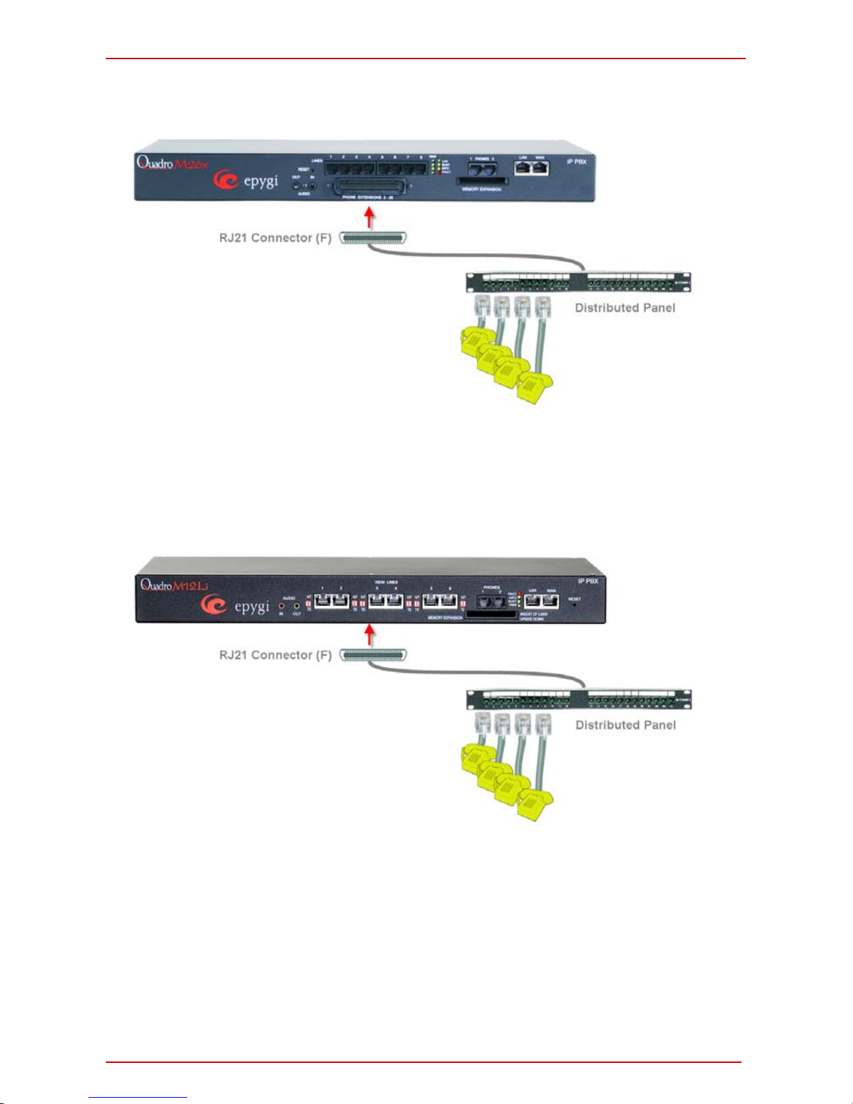
• QuadroM26x additional analog lines connections
Fig. I-25: Installation: QuadroM 26xi connected via RJ21 connectors
• QuadroM26xi additional analog lines connections
Fig. I-26: Installation: QuadroM 26xii connected via RJ21 connectors
OR a multi-cable (RJ21 – RJ11) connection can be applied instead.
QuadroM32x/8L/26x/12Li/26xi; (SW Version 5.3.x) 23

QuadroM32x/8L/26x/12Li/26xi Manual I: Installation Guide Connecting the Hardware
Wires are presented in the table below:
Color Pin (Tip) Pin (Ring) Color FXS Port
White/Blue 26 1 Blue/White 3
White/Orange 27 2 Orange/White 4
White/Green 28 3 Green/White 5
White/Brown 29 4 Brown/White 6
White/Slate 30 5 Slate/White 7
Red/Blue 31 6 Blue/Red 8
Red/Orange 32 7 Orange/Red 9
Red/Green 33 8 Green/Red 10
Red/Brown 34 9 Brown/Red 11
Red/Slate 35 10 Slate/Red 12
Black/Blue 36 11 Blue/Black 13
Black/Orange 37 12 Orange/Black 14
Black/Green 38 13 Green/Black 15
Black/Brown 39 14 Brown/Black 16
Black/Slate 40 15 Slate/Black 17
Yellow/Blue 41 16 Blue/Yellow 18
Yellow/Orange 42 17 Orange/Yellow 19
Yellow/Green 43 18 Green/Yellow 20
Yellow/Brown 44 19 Brown/Yellow 21
Yellow/Slate 45 20 Slate/Yellow 22
Violet/Blue 46 21 Blue/Violet 23
Violet/Orange 47 22 Orange/Violet 24
Violet/Green 48 23 Green/Violet 25
Violet/Brown 49 24 Brown/Violet 26
Violet/Slate 50 25 Slate/Violet Not Used
• Verify the product package contents are complete. Refer to the contents sheet included
in the packaging to determine if all the items were shipped in the box.
• Before you connect the hardware, make sure that all devices are powered off.
• Connect analog phones to the PHONE ports on the Quadro’s rear panel. You may
connect up to two analog phones.
• Connect the E1/T1 port to your PBX or the trunk from the PSTN Central Office Only
after configuring the E1/T1 settings according to the specifications of your PSTN provider
(see Appendix: Pin Assignment of E1/T1
).
• Connect the Ethernet port on your PC via a straight CAT 5 cable with an RJ45 connec-
tor to the LAN socket of the Quadro.
• Connect the IP phones to the switch and attach it to the LAN socket of the Quadro via a
straight CAT 5 cable with an RJ45 connector.
• Connect the WAN port of the Quadro to the Internet service via a cable or DSL modem.
• Power up the DSL or Cable modem first.
• Connect the power cable to the POWER port on the back side of your QuadroM and
plug the power plug into the power outlet.
The red LED (Fault) will glow for several seconds followed by the yellow LED (Info),
which will glow for several minutes. When Info LED is off, the Quadro is operational.
• Power up any hub or switch followed by any PC and other devices on the LAN side.
• Check the LEDs: The green Busy LED must glow continuously. The green ETH, LAN
and WAN LEDs will blink when cables are connected to these ports and all devices are
powered up. If the green LAN and WAN LEDs do not blink, verify cabling and ensure
that all devices are powered up.
QuadroM32x/8L/26x/12Li/26xi; (SW Version 5.3.x) 24
 Loading...