

Epygi QUADRO T1, QUADRO E1 Administrator's Manual

QuadroE1/T1 Manual II: Administrator's Guide
Edition 1, SW Release 3.0.49 and higher, January 2006
QuadroE1/T1 (SW Version 3.0.x)

QuadroE1/T1 Manual II: Administrator's Guide
Table of Contents
Manual I: see Installation Guide
Step-by-step guide to install and configure Quadro basically.
Manual II: Administrator's Guide
0HAbout this Guide...................................................................................................................77H4
1HQuadro’s Graphical User Interface .......................................................................................78H5
2HAdministrator’s Main Page...............................................................................................................79H5
3HRecurrent Buttons............................................................................................................................80H6
4HRecurrent Functional Buttons ..........................................................................................................81H6
5HEntering a SIP Addresses correctly..................................................................................................82H6
6HAdministrator’s Menus .........................................................................................................83H7
7HSystem Menu ...................................................................................................................................84H7
8HSystem Configuration Wizard .............................................................................................................................85H7
9HInternet Configuration Wizard ............................................................................................................................86H9
10HStatus...........................................................................................................................................................87H12
11HGeneral Information...................................................................................................................................88H12
12HNetwork Status..........................................................................................................................................89H12
13HLines Status ..............................................................................................................................................90H14
14HHardware Status........................................................................................................................................91H15
15HSIP Registration Status...............................................................................................................................92H16
16HH323 Registration Status............................................................................................................................93H16
17HIP Routing Configuration..................................................................................................................................94H16
18HConfiguration Management ..............................................................................................................................95H18
19HUpdate Configuration ......................................................................................................................................96H19
20HEvents ..........................................................................................................................................................97H20
21HTime/Date Settings.........................................................................................................................................98H24
22HMail Settings..................................................................................................................................................99H25
23HFirmware Update............................................................................................................................................100H26
24HNetworking Tools............................................................................................................................................101H27
25HDiagnostics....................................................................................................................................................102H28
26HAutomatic Provisioning....................................................................................................................................103H28
27HFeatures........................................................................................................................................................104H29
28HUpload Language Pack ....................................................................................................................................105H29
29HUsers Menu....................................................................................................................................106H30
30HUser Management ..........................................................................................................................................107H30
31HSIP Advanced Settings ...............................................................................................................................108H37
32HH323 Advanced Settings.............................................................................................................................109H37
33HExtension Codecs.......................................................................................................................................110H38
34HChange Admin Password .................................................................................................................................111H39
35HTelephony Menu.............................................................................................................................112H40
36HCall Statistics .................................................................................................................................................113H40
37HRTP Statistics ............................................................................................................................................114H41
38HSIP Settings...................................................................................................................................................115H42
39HH323 Settings................................................................................................................................................116H42
40HRTP Settings ..................................................................................................................................................117H43
41HNAT Traversal Settings....................................................................................................................................118H44
42HLine Settings..................................................................................................................................................119H47
43HLoopback Settings......................................................................................................................................120H48
44HE1/T1 Settings ...............................................................................................................................................121H49
45HGain Control ..................................................................................................................................................122H57
46HCall Routing...................................................................................................................................................123H57
47HVoIP Carrier Wizard ........................................................................................................................................124H63
48HRADIUS Client Settings ...................................................................................................................................125H65
49HDial Plan Settings ...........................................................................................................................................126H66
50HInternet Uplink Menu.....................................................................................................................127H67
51HPPP Dial Settings ............................................................................................................................................128H67
52HAdvanced PPP Settings ...............................................................................................................................129H67
53HISP Authentication Settings .............................................................................................................................130H68
54HFirewall and NAT ............................................................................................................................................131H69
55HAdvanced Firewall Settings..........................................................................................................................132H69
56HFiltering Rules ................................................................................................................................................133H69
57HService Pool ..............................................................................................................................................134H72
QuadroE1/T1 (SW Version 3.0.x)

QuadroE1/T1 Manual II: Administrator's Guide
58HIP Pool .....................................................................................................................................................135H73
59HLAN Services Menu.........................................................................................................................136H75
60HDNS Settings .................................................................................................................................................137H75
61HDHCP Settings for the LAN Interface .................................................................................................................138H75
62HRegistration Form .......................................................................................................................... 139H76
63HQuadroE1/T1’s Feature Codes............................................................................................140H77
64HEstablishing a call .......................................................................................................................... 141H77
65HUsing Quadro’s PBX Services .........................................................................................................142H77
66HAdministrator Login ....................................................................................................................... 143H77
67HQuadroE1/T1’s Auto Attendant Services ............................................................................144H78
68HCall Codes Available in Auto Attendant .......................................................................................... 145H78
69HAppendix: System Default Settings ....................................................................................146H79
70HAppendix: Glossary.............................................................................................................147H81
71HAppendix: Software License Agreement .............................................................................148H86
QuadroE1/T1 (SW Version 3.0.x)

QuadroE1/T1 Manual II: Administrator's Guide About this Administrator's Guide
About this Guide
The QuadroE1/T1 Manual is divided into two parts:
• Manual-I: Installation Guide
gives step-by-step instructions to provision the Quadro and configure the phone extension with the Epygi SIP Server. After successfully
configuring the Quadro, a user will be able to make SIP phone calls to remote Quadro devices, make local calls to the PSTN and access the
Internet from devices connected to the LAN.
• Manual-II: Administrator's Guide explains all QuadroE1/T1 management menus. It includes the available call codes and a list of all System
Default Values, too
H72H149HUQuadro’s Graphical User InterfaceUH introduces the Quadro's graphical user interface and explains all recurrent buttons.
UAdministrator’s Graphical User InterfaceU explains each of the Administrator's management on the main page of the Quadro management.
150HUQuadro’s Call CodesU describes the Quadro’s call codes that enable the user to navigate through Quadro’s services from a phone handset.
Quadro’s Auto Attendant Services
auto attendant.
151HUAppendix: System Default SettingsU lists all factory defaults.
Appendix: Glossary
defines some technical terms.
Appendix: Software License Agreement
U explains the operation of the Quadro's auto attendant and lists the call codes that may be used to enter the
includes the terms and conditions of using the Quadro's hardware and software.
QuadroE1/T1; (SW Version 3.0.x) 4
QuadroE1/T1 Manual II: Administrator's Guide Quadro’s Graphical User Interface
Quadro’s Graphical User Interface
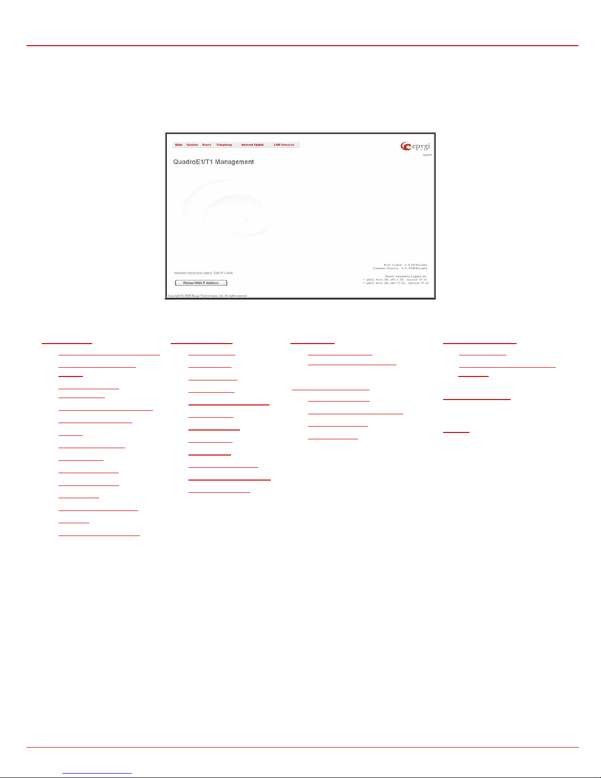
Administrator’s Main Page
After logging in as an administrator, the page Quadro Management is displayed. Here the adm inistrator may access the following settings and
perform the following actions:
Fig. II-1: Quadro Administrator’s page
152HSystem Menu
• 153HSystem Configuration Wizard
• 154HInternet Configuration
Wizard
• 155HStatus156HIP Routing
Configuration
• 157HConfiguration Management
• 158HUpdate Configuration
• 159HEvents
• 160HTime/Date Settings
• 161HMail Settings
• 162HFirmware Update
• 163HNetworking Tools
• 164HDiagnostics
168HTelephony Menu
• 169HCall Statistics
• 170HSIP Settings
• 171HH323 Settings
• 172HRTP Settings
• 173HNAT Traversal Settings
• 174HLine Settings
• 175HE1/T1 Settings
• 176HGain Control
• 177HCall Routing
• 178HVoIP Carrier Wizard
• 179HRADIUS Client Settings
• 180HDial Plan Settings
Users Menu
• 182HUser Management
183HChange Admin Password
1)
Internet Uplink Menu
• 185HPPP Dial Settings
• 186HISP Authentication Settings
• 187HFirewall and NAT
• 188HFiltering Rules
• 165HAutomatic Provisioning
• 166HFeatures
• 167HUpload Language Pack
The functional button Renew Wan IP Address appears on the administrator’s main Q uadro Management page if the Quadro device acts as a
DHCP client. The Renew WAN IP Address button is used to get a new WAN IP address for example when the Quadro moves to another network.
The functional button Establish Your Internet Connection Now respectively Terminate Your Internet Connecti on Now appears on the Quadro
Management page if PPPoE is used as the WAN interface protocol.
The button Please Check Your Pending Events will be displayed on the administrator Main Menu page if any new system events exist. The link
leads to the Events page that can also be accessed from the System menu.
The list of Users currently logged into the system is seen in the lower right corner of the Administrator's Main Menu. Information about the IP
address of a user, the username used to log in and the time until the next automatically logout is provided herein. The idle session timeout is to 20
minutes. If no action is performed during that time, user will be automatically moved to the Login page and will be requested to login again.
The link Refresh in appears in the lower right corner beside the field displaying the number of seconds until the next refresh. It is used to perform a
manual reload of the page. If a page with a Refresh counter is left open, the session time-out counter will be updated periodically and the logout
timeout will never expire.
The current version of the Quadro's firmware and of its boot loader is shown in the lower right corner of the administrator’s main menu, followed by
the list of users currently logged into the system. Information about IP addresses users accessed Quadro from, the username of the logged-in user
and the time until the next automatic logout is provided here. The idle session timeout is set to 20 minutes. If no action is done during that time, the
user automatically will be moved to the login page and will be requested to login again.
LAN Services Menu
• 190HDNS Settings
• 191HDHCP Settings for the LAN
Interface
192HRegistration Form
(in menu tree only)
193HLogout
QuadroE1/T1; (SW Version 3.0.x) 5
QuadroE1/T1 Manual II: Administrator's Guide Quadro's Graphical Interface
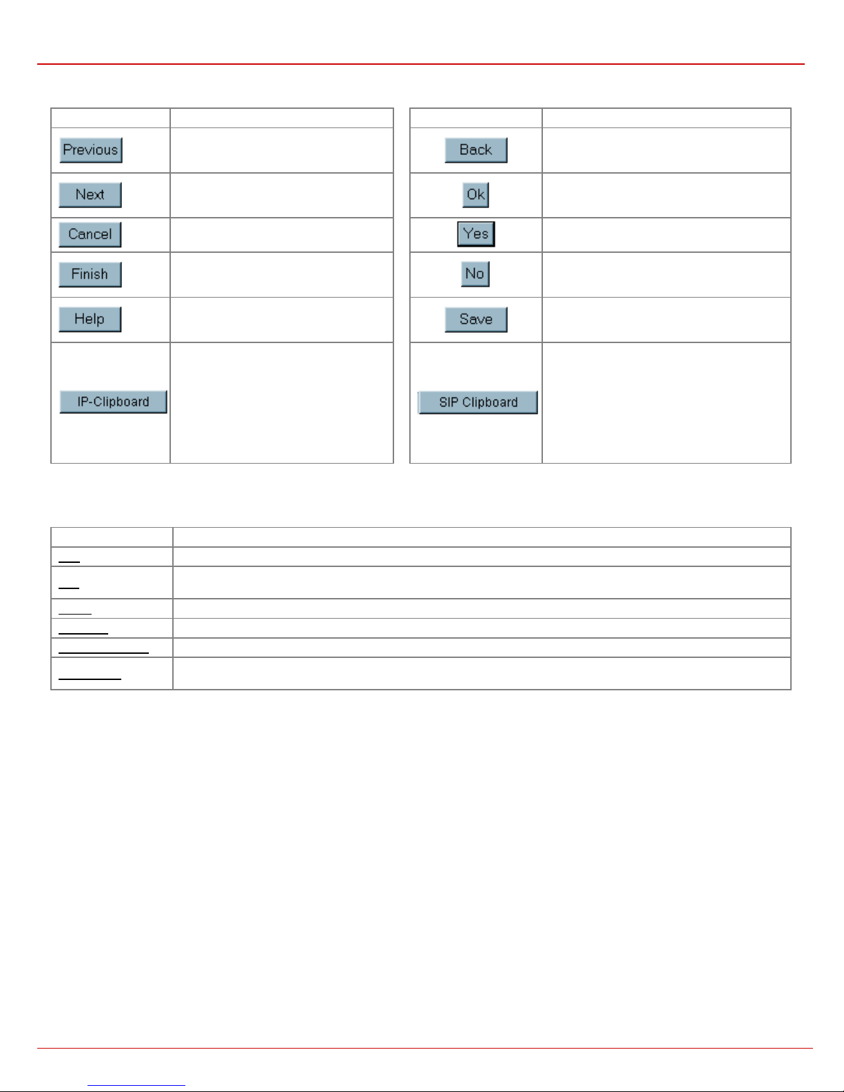
Recurrent Buttons
Button Description Button Description
This button leads back to the previous
page of a fixed sequence of pages (used
mainly in wizards).
This button leads onward to the next page
of a fixed sequence of pages (used mainly
in wizards).
This button discards the latest, not yet
confirmed entries.
This is the last button of a fixed sequence
of pages that completes and saves the
entries of the whole sequence.
This button opens the help page
belonging to the currently active Quadro
management page.
This button opens a window where the last
inserted IP addresses are listed. It is a
kind of clipboard that helps the user to
make quick selection of an IP address in
case it has been already used in the past,
thus to avoid typing it again. The clipboard
can hold up to 10 IP addresses, a new IP
address will replace the oldest one from
the list.
This button leads back to the page you have
been on before.
This button confirms an operation you started
before.
This button confirms an operation you chose
before.
This button discards an operation you chose
before.
This button saves the settings modified on the
currently active management page.
This button opens a window where the last
inserted SIP addresses are listed. It is a kind of
clipboard that helps the user to make quick
selection of a SIP address in case it has been
already used in the past, thus to avoid typing it
again. The clipboard can hold up to 10 SIP
addresses, a new SIP address will replace the
oldest one from the list.
Recurrent Functional Buttons
In connection with tables, the following buttons - among others - usually occur:
Functional Button Description
Add Allows adding a new record to the displayed table. A new page will be displayed to enter any new settings.
Edit
Delete Deletes the selected entry(s) of a table. A warning message will demand a confirmation before deleting an existing entry.
Select All Selects all table entry(s)for example for further deletion.
Inverse Selection Inverses an existing selection of table entry(s). If no entries are selected, clicking the button will select all records.
Refresh in...
Most of the tables offer the option to sort the entries in ascending or descending order by clicking the headings of the column s. A small arrow beside
the column heading will show the direction of sorting - upward or downward. The entries of the table can be selected by the assigned checkboxes one at a time, for the most part - in order to edit or delete them.
Allows modifying the settings of the record selected by its checkbox. Normally only one record may be selected. A new
page will be displayed to enter the modified settings.
May occur in the upper right corner of a page. It displays the number of seconds remaining until the next refresh of the page
and it may be used to reload the page manually.
Entering a SIP Addresses correctly
Calls over IP are implemented based on Session Initiating Protocol (SIP) on the Quadro. When making a call to a destination tha t is somewhere on
the Internet, SIP address must be given.
SIP addresses have to be specified in one of the following formats:
“display name” <username@ipaddress:port>
“display name” <username@ipaddress>
username@ipaddress:port
username@ipaddress
username
Particularly the following combinations can be used for your
convenience:
The display name and the port number are optional parameters in the
SIP address. If a port is not specified, 5060 will be set up as the default
one. The range of valid ports is between 1024 and 65536.
A flexible structure of wildcards is allowed. In comparison with a
wildcard, the “?” character stands for only one unknown digit and the “*”
character stands for any number of any digits.
Please Note: Wildcards are available for caller addresses only. No
wildcard characters are allowed for called party addresses.
• *@ipaddress - any user from the specified SIP server
• username@* - a specified user from any SIP server
• *@* - any user from any SIP server
Attention: Wildcards are available for caller addresses only (for called party addresses no wildcard characters are allowed).
QuadroE1/T1; (SW Version 3.0.x) 6

QuadroE1/T1 Manual II: Administrator's Guide Administrator's Graphical User Interface
Administrator’s Menus
System Menu
Fig. II-1: System Menu in Dynamo theme
Fig. II-2: System Menu in Plain theme
System Configuration Wizard
The System Configuration Wizard is the helpful tool for the administrator to define the Quadro’s Local Area Network settings and to specify
regional configuration settings to make Quadro operational in its LAN. The System Configuration Wizard MUST be run upon Quadro's first
startup to make sure that it works properly in its network environment. The Wizard allows navigating through the following basic configuration
parameters and settings:
• System Configuration (see below)
• 194HDHCP Settings for the LAN Interface
• Regional Settings and Preferences (see below)
DHCP Settings for LAN are described in the chapters below
while LAN configuration and regional settings will be described
in the current chapter.
Please Note: It is strongly recommended to leave the
factory default settings if their meanings are not fully
clear to the administrating person.
Fig. II-3: System Configuration Wizard - Start page
QuadroE1/T1; (SW Version 3.0.x) 7
QuadroE1/T1 Manual II: Administrator's Guide Administrator's Graphical User Interface
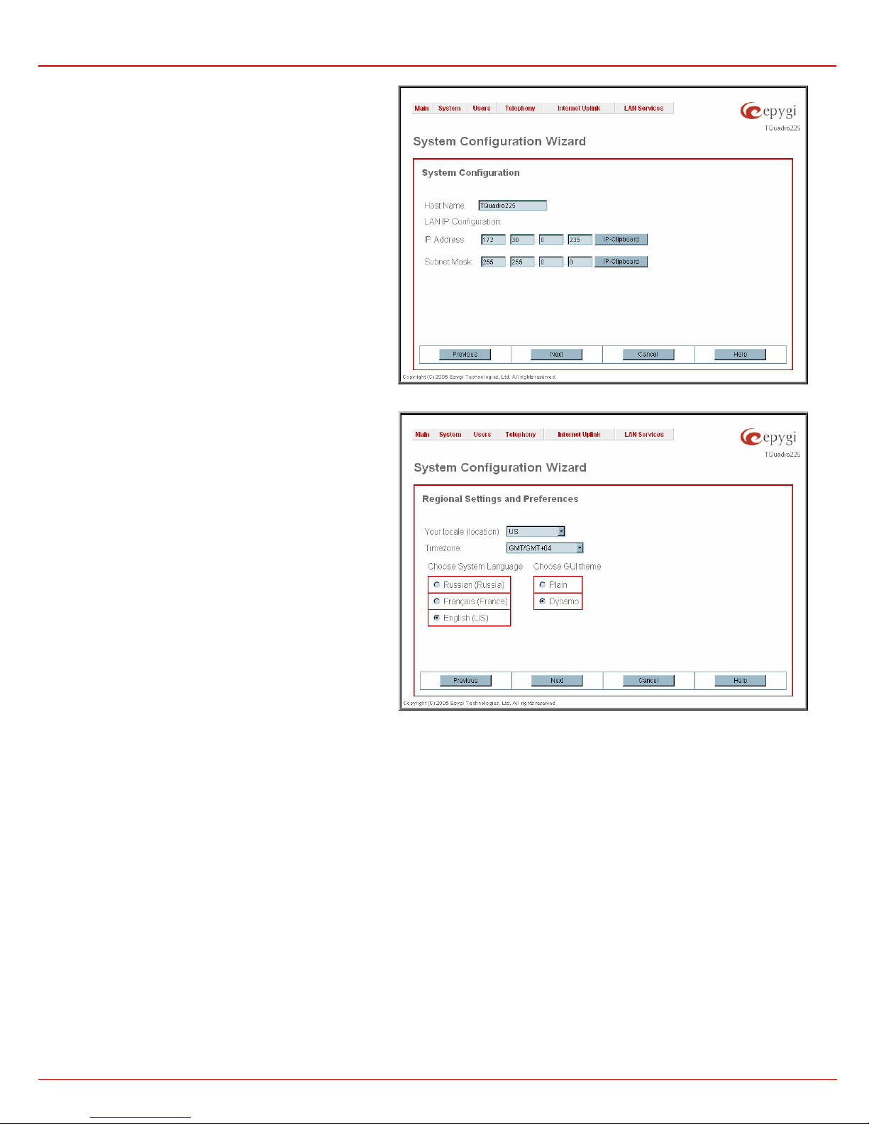
The System Configuration page contains the host name, IP
address and Subnet Mask information about the Quadro LAN
interface. These settings make Quadro available to the internal
network.
The System Configuration page offers the following input
options:
Host Name requires a host name for the Quadro device.
IP Address requires the Quadro host address for the LAN
interface.
Subnet Mask requires the Quadro hosts’ Subnet Mask.
Fig. II-4: System Configuration Wizard - System Configuration page
The Regional Settings a nd Preferences are used to select
settings specific to the location of the Quadro.
This is important for the functionality of the voice subsystem.
The Regional Settings and Preferences page has two drop
down lists to select the Location (country) and a
corresponding Timezone and a manipulation radio button
group to choose:
• System Language – selection is available only when
custom Language Pack has been uploaded and is used
to enable custom language for system voice messages or
turn back to default (English).
• GUI Theme - selection used to select the GUI theme
style of the web based configuration pages.
Fig. II-5: System Configuration Wizard - Regional Settings page
QuadroE1/T1; (SW Version 3.0.x) 8
QuadroE1/T1 Manual II: Administrator's Guide Administrator's Graphical User Interface
Internet Configuration Wizard
The Internet Configuration Wizard is the helpful tool for the administrator to configure the WAN interface settings and to adjust Quadro’s
connectivity with an external network. The Internet Co nfiguration Wizard MUST be run if it is desired for Quadro to be connected to the
Internet. The Wizard allows navigating through the following basic configuration parameters and settings:
• Uplink configuration (see below)
For WAN Interface protocol PPPoE:
• PPP Configuration
• WAN Interface Configuration
• 195HDNS Settings
• 196HISP Authentication Settings
For WAN Interface protocol Ethernet:
• WAN IP Configuration
• WAN Interface Configuration
• 198HDNS Settings
• 197HPPP Dial Settings
The Switch to Auto Provisioning link moves you to the
provisioning mechanism.
199HAutomatic Provisioning page where Quadro can be configured by the automatically
All the settings of the Internet Configuration Wizard are
described in the chapters below except those for the IP settings,
which will be described in this chapter.
Please Note: It is strongly recommended to lea ve the factory
default settings if their meanings are not fully clear to the
administrating person.
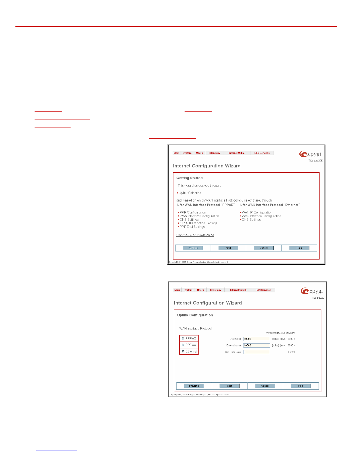
The Uplink Configuration page allows to select the Quadro‘s WAN
interface connection type and its bandwidth settings. These settings
make Quadro available to the external network.
Depending on the Uplink Interface Protocol selection, the page
following the Uplink Configuration page is different. Thus if
PPPoE is selected, the next page will be PPP Configuration, while
selecting Ethernet will bring up the WAN IP Configuration page.
The Uplink Configuration page offers the following components:
The WAN Interface Protocol radio buttons are used to choose
between Point-to-Point Protocol over Ethernet (PPPoE) and
Ethernet. Selection depends on the requirements of the ISP
(Internet Service Provider).
PPPoE - turns on the PPP over Ethernet connection type.
PPPoA – selection is only present when corresponding
interfaces are present on the Quadro and are used to turn on
the PPP over ADSL/G.SHDSL connection type.
Ethernet - turns on the Ethernet connection type.
The WAN Interface Bandwidth settings allow the specification of the upstream and downstream speeds in kbit/s, helping to assure the quality of IP
calls. An IP call looses the voice quality if there will be no available bandwidth. In case of reaching the borders of bandwidth, another IP call will be
declined.
Fig. II-7: Internet Configuration Wizard - Uplink Configuration page
Fig. II-6: Internet Configuration Wizard - Start page
QuadroE1/T1; (SW Version 3.0.x) 9
QuadroE1/T1 Manual II: Administrator's Guide Administrator's Graphical User Interface
The bandwidth provided by the ISP has to be specified in the text fields Upstream Speed and Downstream Speed. The default entry in both fields
is 10000, the maximum bandwidth of a 10 MB Ethernet. But most providers offer a smaller bandwidth than these 10000 kbit/s.
The bandwidth required by an IP call depends on the codecs used and is listed in the tables below:
Required Bandwidth for Standard Packets:
msec.
10 105 58 66 73 81 50
20 84 37 45 52 60 29
30 77 30 38 45 53 22
40 73 26 34 42 50 18
50 71 24 32 40 48 16
60 70 23 30 38 46 15
Required Bandwidth for Encrypted Packets (in the case a VPN is used):
msec.
10 148 98 105 117 123 92
20 105 59 65 74 80 49
30 91 43 52 60 66 35
40 84 37 45 53 61 29
50 80 33 41 48 56 25
60 77 30 37 46 53 22
The Min Data Rate text field requires the amount of upstream bandwidth that ought to remain for data applications even if voice applications use the
entire available upstream bandwidth. The value selected here needs to be smaller than the upstream bandwidth and is measured in kbit/s.
G.711u/G.711a G.726-16 G.726-24 G.726-32 G.726-40 G.729a
G.711u/G.711a G.726-16 G.726-24 G.726-32 G.726-40 G.729a
Needed bandwidth in kbit/s using the Codecs: Packet Size in
Needed bandwidth in kbit/s using the Codecs: Packet Size in
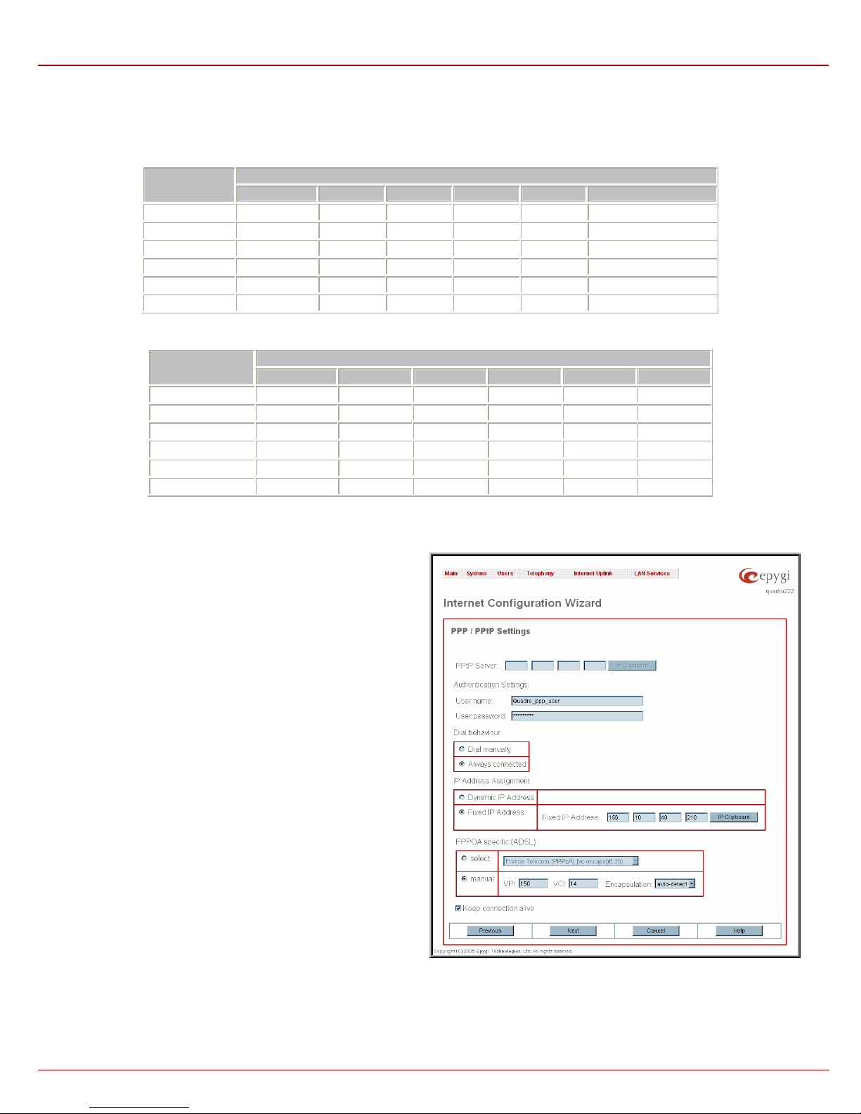
If PPPoE is selected as the WAN Interface Protocol then the PPP
Configuration page is opened next.
The PPP Configuration page offers the following components:
IP Address Assignment radio buttons are used to configure the IP
address for the Quadro device:
• Dynamic IP Address - switches to the dynamic IP address
assignment mechanism.
• Fixed IP Address - switches to the fixed IP address assignment
mechanism.
Fixed IP Address requires entering the user defined IP address for
the Quadro device on the WAN interface.
QuadroE1/T1; (SW Version 3.0.x) 10
Fig. II-8: Internet Configuration Wizard – PPP/PPtP Configuration page
QuadroE1/T1 Manual II: Administrator's Guide Administrator's Graphical User Interface
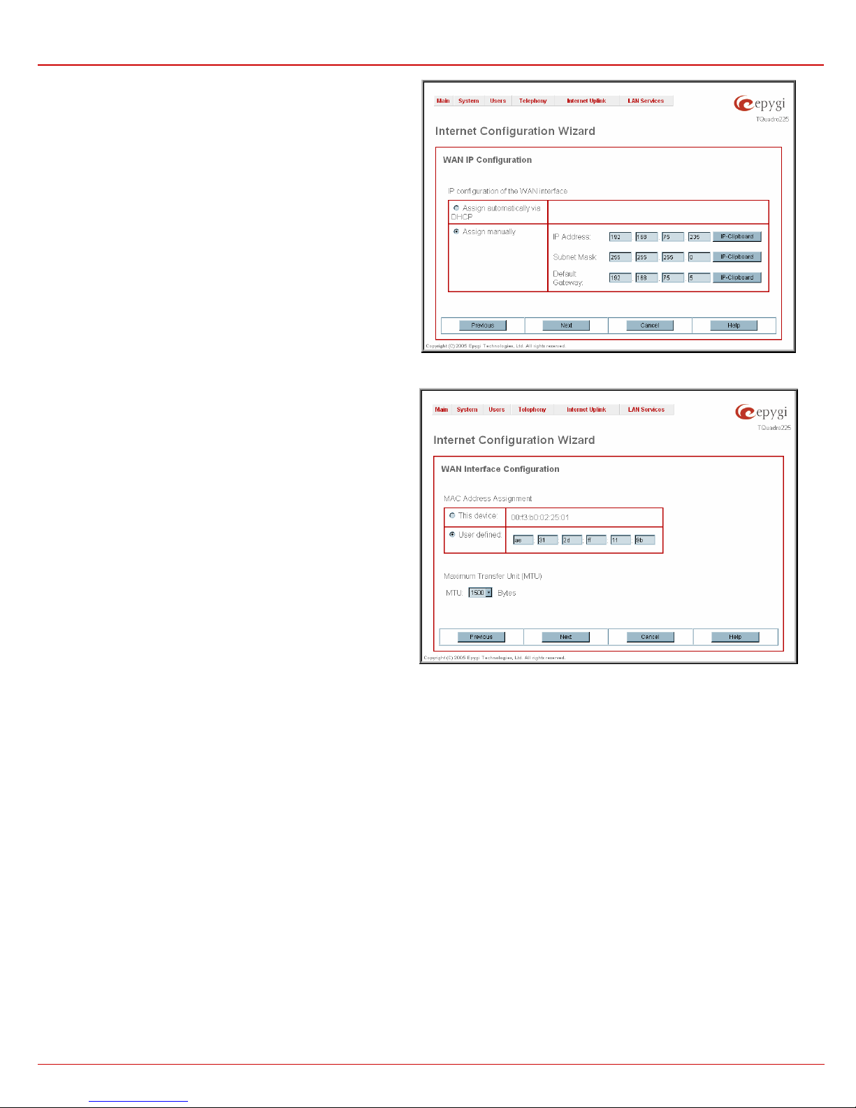
The WAN IP Configuration page only is displayed if Ethernet has
been selected to be the uplink protocol. It offers the following
components:
The Assign automaticall y via DHCP radio-button selection switches
to automatic retrieval of the WAN IP address from a DHCP server at
the ISP/uplink.
Please Note: DHCP referred to here is the one running on the
provider’s side and not the Quadro’s personal DHCP server.
The Assign Manually radio-button switches to the manual
adjustment of IP settings. This selection requests the following
parameters:
IP Address requires the IP address for the Quadro WAN interface.
Subnet Mask requires the subnet mask for the Quadro device WAN
interface.
Default Gateway requires the IP address of the router all packets are
sent to, for example, the router of the provider.
Fig. II-9: Internet Configuration Wizard - WAN IP Configuration page
The WAN MAC Address Configuration page may be used to
modify the MAC address of the Quadro. This might be necessary, if
the ISP (Internet Service Provider) requires a certain MAC address,
for example, for authentication. The page offers the following
components:
MAC Address Assignment manipulation radio-buttons:
• This Device turns to the default MAC address of the Quadro.
• User Defined requires user defined MAC Address.
MTU drop down list allows to select the maximum packet size on the
Ethernet (in bytes). MTU is used to fragment the packets before
transmitting them to the network. MTU preferred value is dependent
on the Ethernet connection type. The default MTU size is 1500 Bytes
for Ethernet and 1400 Bytes for PPPoE.
Fig. II-10: Internet Configuration Wizard - WAN MAC Address Configuration page
QuadroE1/T1; (SW Version 3.0.x) 11
QuadroE1/T1 Manual II: Administrator's Guide Administrator's Graphical User Interface
Status
The system status window displays non-editable tables providing extensive status information about Quadro: 200HGene ral Information, 201HNetwork Status,
202HLines Status, 203HMemory Status, 204HHardware Status, 205HSIP Registration Status and 206HH323 Registration Status. The links on this page lead to device Transfer
Statistics, user mailboxes and supplementary services configuration pages.
The System Status page has several tables providing system information.
General Information
The General Information page includes the following
information:
• Uptime duration - Period Quadro is on since last
reboot.
• Device Hostname - Quadro device host name.
• Qua dro Operating System - Quadro operating system
version.
• Application Software - Software and file system
versions of the Quadro.
• Boot Loader - Quadro boot loader version.
•
DSP Software - Quadro DSP software version and the
date of build.
•
Preinstalled Languages – field is present only when
multiple languages are preinstalled on the device and
indicates the system default languages.
•
Language Pack – field is present only when custom
language pack is uploaded and indicates its version.
Fig. II-11: Quadro Status - General Information page
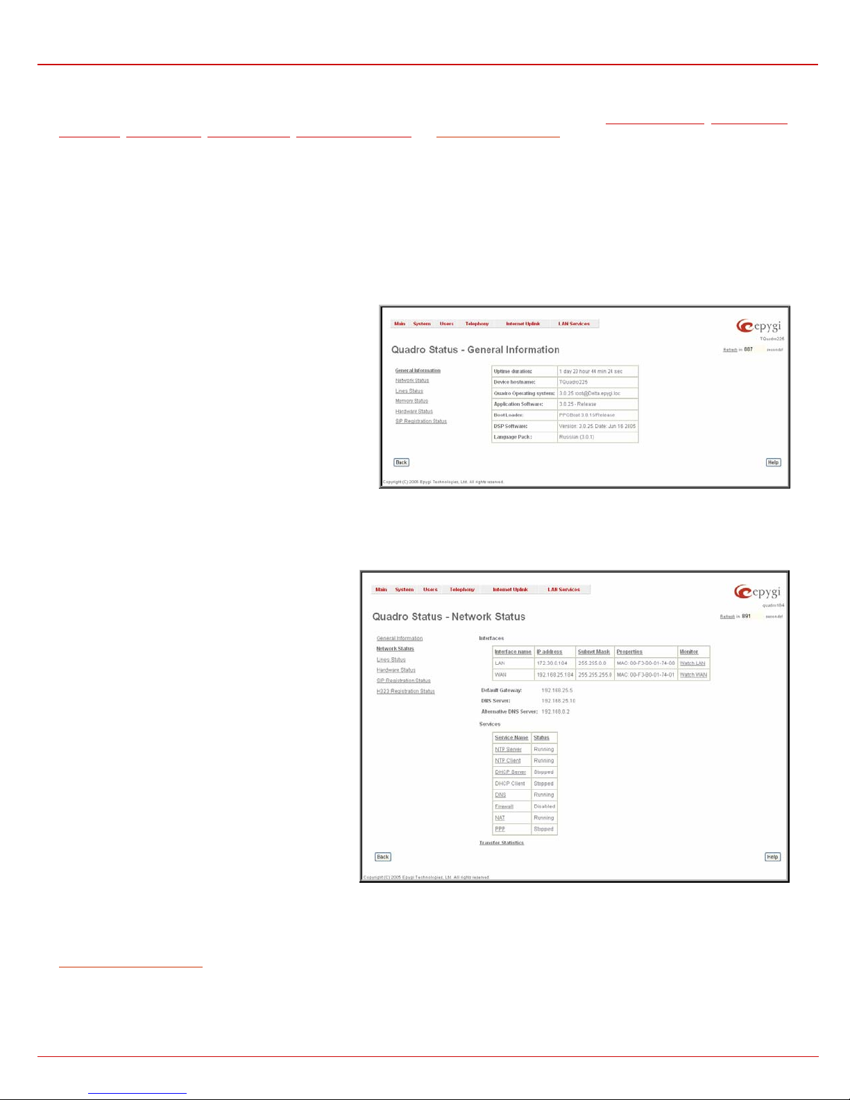
Network Status
The Network Status page includes the following
information about Interfaces:
Interface Name lists the Network interfaces available on
the Quadro (LAN and WAN).
IP Address lists the IP addresses corresponding to each
network interface.
Subnet Mask lists the subnet masks corresponding to
each network interface.
Properties lists either the MAC address corresponding to
each network interface on the Quadro.
Monitor includes links to survey LAN and WAN traffic
correspondingly.
• Received Bytes
• Received Packets
• Received Errors
• Received Drop Errors
• Received Overrun
Errors
• Received MultiCast
Packets
When opening the corresponding interface statistics window, no traffic values are displayed at first. Then every one minute, traffic statistics will be
updated. The tables serve as a kind of counter.
DNS Server, Alternative DNS Server and Default Gateway - displays the Quadro settings corresponding to what has been configured with the
207HSystem Configuration Wizard.
Services (NTP Server and Client, DHCP Server and Client, DNS, Firewall, NAT, PPP) statuses: stopped or running.
Transfer Statistics - link to the Transfer Statistics page.
• Transmitted Bytes
• Transmitted Packets
• Transmitted Errors
• Transmitted Drop
Errors
• Transmitted Carrier
Errors
• Transmitted Collisions
Fig. II-12: Quadro Status Network Status page
QuadroE1/T1; (SW Version 3.0.x) 12
QuadroE1/T1 Manual II: Administrator's Guide Administrator's Graphical User Interface
The Transfer Statistics page allows a user-defined statistic
table depending on the transmit/receive value (criteria),
interface type and time period. It contains the following
components:
Time Range of statistic table - the drop down list includes the
period(in days) statistics data is to be collected and the
corresponding diagram charts are to be built.
Interface - the drop-down list offer the values:
• WAN - Wide Area Network (WAN) events only
• LAN - Local Area Network (LAN) events only
The area Receive Values:
Fig. II-13: Transfer Statistics page
• Receive Bytes - number of received bytes
• Receive Packets - number of received Ethernet packets
• Receive Errors - number of received packets containing
errors
• Receive Drop Errors - number of received packets that
have been discarded
• Recei ve Overrun Errors - number of received overrun
errors that occur when the receive buffer is not large
enough to hold all incoming packets. This error mostly
appears because of a slow receiving system.
• Receive MultiCast Packets - number of received
broadcast packets
The area Transmit Values:
• Transmit Bytes - number of transmitted bytes
• Transmit Packets - number of transmitted Ethernet
packets
• Transmit Errors - number of transmitted packets
containing errors
• Transmit Dr op Errors - number of transmitted packets
that have been discarded
• Transmit Carrier Errors - number of transmit carrier
errors that occur because of a defective or lost
connection on the Ethernet link
• Transmit Collisions - number of transfer errors that
occurred during a simultaneous packet transmission from
both sides
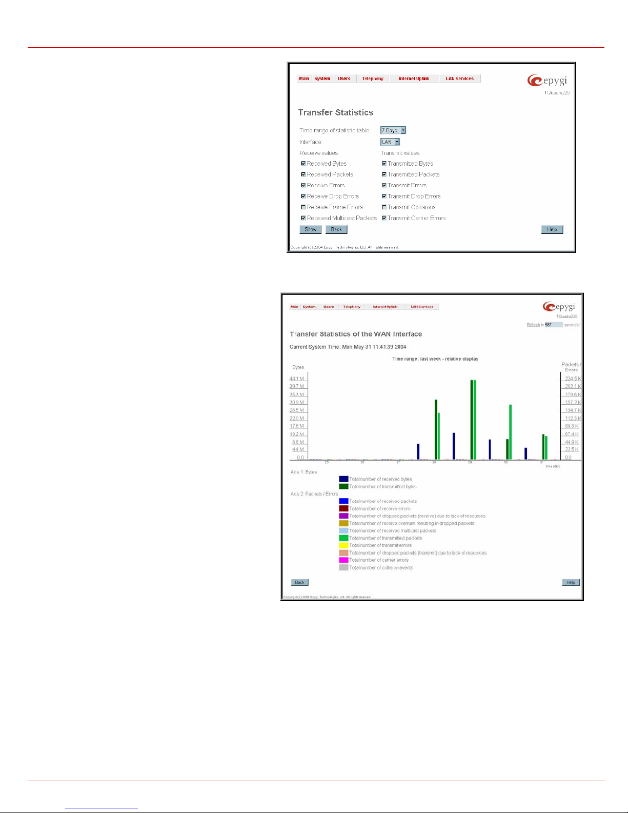
To show the Transfer Statistics Diagram Charts, select the desired criteria and click Save to generate the corresponding chart.
Fig. II-14: Transfer Statistics Diagram Chart
QuadroE1/T1; (SW Version 3.0.x) 13
QuadroE1/T1 Manual II: Administrator's Guide Administrator's Graphical User Interface
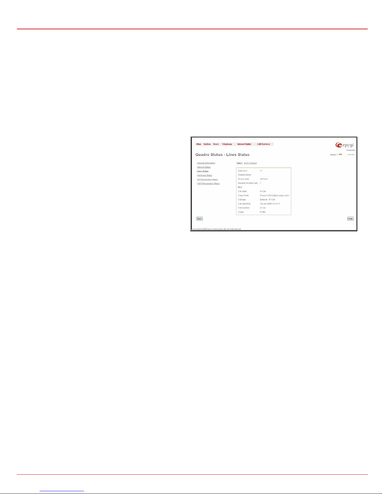
Lines Status
The page Quadro Status - Lines Status shows the current status of the ext ension and E1/T1 t runk. Since only one line information is displayed at a
time, the Phone1 and E1/T1 Trunk buttons serve to navigate through the lines information.
The Lines Status table displayed for Phone1 lines includes a group of
static and dynamic parameters. Static parameters are displayed
always, while dynamic parameters only appear whenever an event
takes place on the extension.
Static Parameters:
Extension - the extension number of the selected telephone line
Display Name – the corresponding name
Phone State - On hook or off hook
Number of Active Calls – that are currently present on the phone.
Dynamic Parameters:
Call State – the current state of the extension (in call, waiting,
busy, call out, ring in etc.)
Caller Party – this parameter appears whenever a call is received
and indicates the caller extension, the IP address or a phone
number depending on the call type
Called Party – this parameter appears whenever a call is placed
and indicates the destination extension, the IP address or a phone
number depending on the call type
Call Type – shows whether the call is Internal or External and
whether it is a PSTN, PBX or IP Call
Call Start Time – call start date and time
Call Duration – current call duration
RX Codec shows the codec used to encrypt the incoming packets.
TX Codec shows the codec used to encrypt the outgoing packets.
If RX and TX codecs are the same, one Codec field will be
displayed instead.
Fig. II-15: Line Status – Line Status page upon established call
QuadroE1/T1; (SW Version 3.0.x) 14

QuadroE1/T1 Manual II: Administrator's Guide Administrator's Graphical User Interface
The Line Status for E1/T1 Trunk displays the list of available timeslots
(in E1 mode, 30 active timeslots both for CAS and CCS signaling
types; in T1 mode, 24 timeslots for CAS signaling and 23 timeslots for
CSS signaling type) and their settings (Route Incoming Call to,
Allowed Call Type and Timeslot State). When Timeslot is in the call,
information about call direction (incoming or outgoing), Caller Party,
Called Party and Call Duration is displayed.
E1/T1 Channel Usage Statistics link refers to the page where traffic
statistic table for E1/T1 channel can be composed. It contains the
following components:
Time Range of statistic table - the drop down list includes the
periods (days) for that statistics data is to be collected and for that
a diagram chart is to be built.
Incoming Calls – indicates incoming E1/T1 call statistics in the
output chart.
Outgoing Calls - indicates outgoing E1/T1 call statistics in the
output chart.
Maximum Active Calls – indicates E1/T1 active calls with
maximal duration.
To show the E1/T1 Channel Usage Statistics select the desired
criteria and click Show to build the corresponding chart (looks like
Transmit Statistics Diagram, see Network Status).
Fig. II-16: Line Status – Line Status page for E1/T1 trunk
Hardware Status
The Hardware Status table displays a list of the hardware
devices present and currently available on the Quadro board. The
hardware device version number and additional comments about
its state are indicated here.
Fig. II-17: Hardware Status page
QuadroE1/T1; (SW Version 3.0.x) 15
QuadroE1/T1 Manual II: Administrator's Guide Administrator's Graphical User Interface
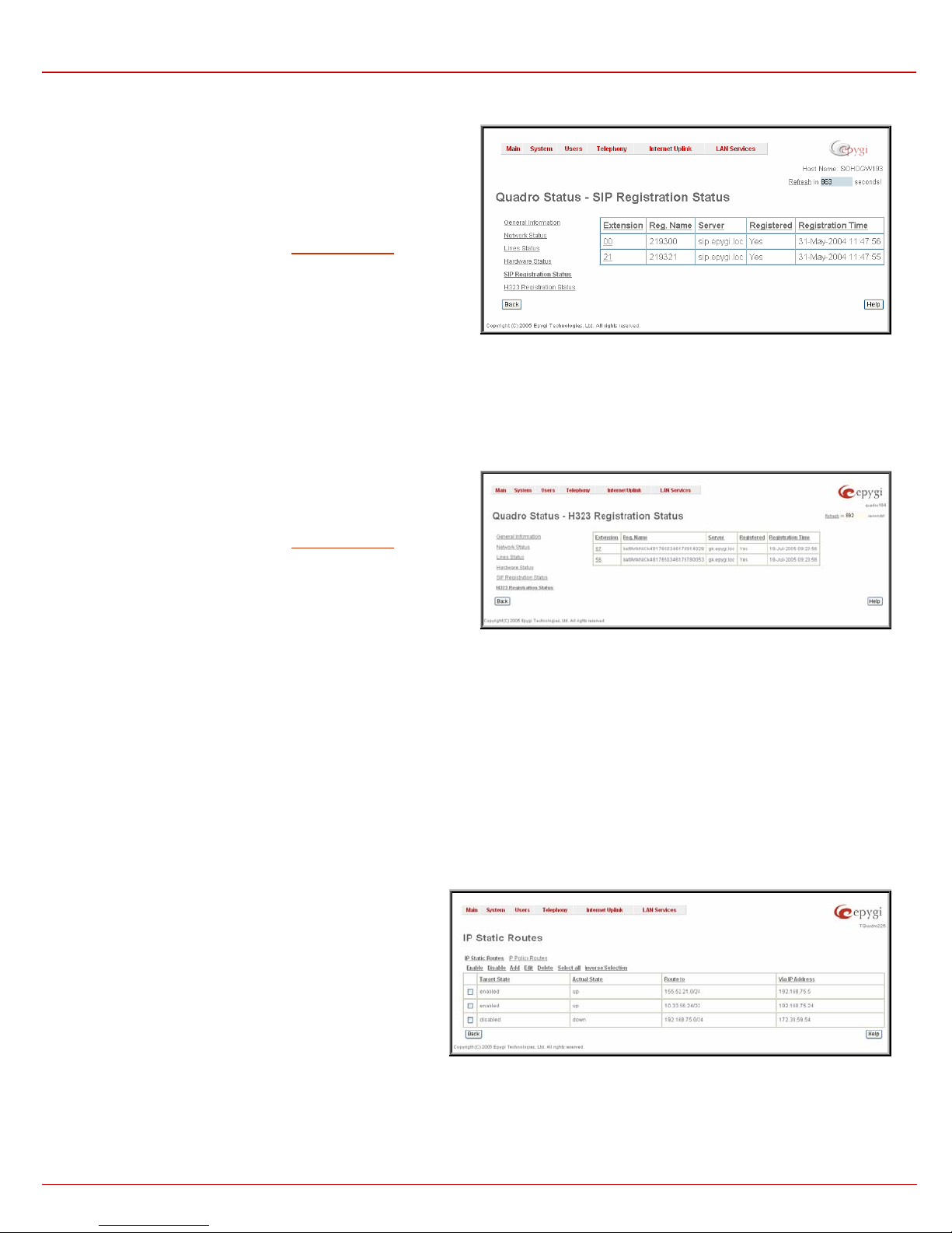
SIP Registration Status
The SIP registration Status is a table displaying the SIP registration
status of the Quadro extensions. The table contains a list of all the
registered extensions of Quadro, information about SIP registration
states for them, addresses of SIP servers where they are registered (if
so), registration date and time, as well as SIP registration names. By
clicking on the row heading, the table will be sorted by the selected
column. Upon sorting (ascending or descending), arrows will be
displayed next to the column heading.
The links inside the table link you to the
208HUser Management – Edit Entry
page where the extension’s SIP registration settings may be altered.
The Detected Connection Type field displays the connection type
Quadro currently is acting in (direct connection or behind NAT). If
Quadro is acting behind NAT, the NAT machine IP address is also
displayed.
Fig. II-18: SIP Registration Status page
H323 Registration St atus
The SIP registration Status is a table displaying the H.323 registration
status of the Quadro extensions. The table contains a list of all the
registered extensions of Quadro, information about H.323 registration
states for them, addresses of H.323 gatekeepers where they are
registered (if so), registration date and time, as well as H.323
registration names. By clicking on the row heading, the table will be
sorted by the selected column. Upon sorting (ascending or descending),
arrows will be displayed next to the column heading.
The links inside the table link you to the
page where the extension’s H.323 registration settings may be altered.
The Detected Connection Type field displays the connection type
Quadro currently is acting in (direct connection or behind NAT). If
Quadro is acting behind NAT, the NAT machine IP address is also
displayed.
209HUser Management – Edit Entry
Fig. II-19: H.323 Registration Status page
IP Routing Configuration
Routing is used to relay information across the Internet from a source to a destination. Along the way, at least one intermediate node is typically
encountered. Routing is often confused with bridging, which may seem to accomplish precisely the same thing to the casual observer.
Quadro’s IP Routing service allows to route IP packets from one destination to another (or to a specified router) through Quadro.
The IP Routing Configuration page is used to make IP Static and IP Policy routes for IP packets routing and has two tables.
IP Static Routes are used to forward IP packets from the
Network, where the Quadro is connected, to the specified
destination.
The IP Static Routes table displays all established IP static
routes with their parameters: Target State for the state of the
route (enabled or disabled), Actual State for the state of the route
connection (up, down or erroneous), Route To for the subnet
where the incoming packets should be routed and Via IP Address
for the router IP address incoming packets should be routed
through.
Add opens the Add IP Static Route page where a new static
route can be established.
Enable/Disable are used to activate/deactivate selected route(s).
At least one route should be selected in order to use these
functions, otherwise the error message appears: “No record(s)
selected.”
Fig. II-20: IP Static Routing table
QuadroE1/T1; (SW Version 3.0.x) 16
QuadroE1/T1 Manual II: Administrator's Guide Administrator's Graphical User Interface
The page Add IP Static Route offers the following components:
Route To requires the IP address and subnet mask of the
destination the IP packet ought to be forwarded to.
Via IP address requires the IP address of the subsequent router
for IP packet forwarding to the specified destination.
Attention: The rule with the longest subnet (smallest IP range)
will take effect when having two or more IP Static routing rules
with the coinciding subnets.
Fig. II-21: Add IP Static Routing page
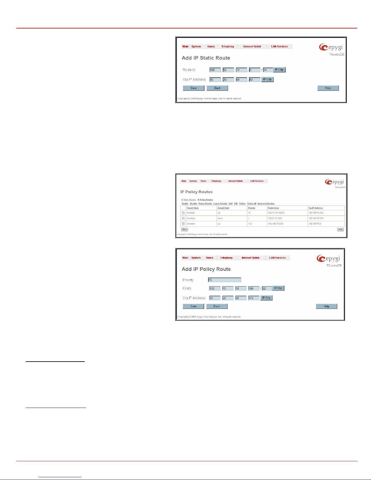
IP Policy Routes allow IP packets forwarding to the specified
router depending on the source IP address as well as defining the
priority for the current routing rule.
The IP Policy Routes table displays all specified IP policy routes
with their parameters: Target State for the state of the route
(enabled or disabled), Actual State for the state of the route
connection (up, down or erroneous), Priority for the route priority,
Route From for the subnet, routed packets come from and Via IP
Address for the router IP address incoming packets should be
routed through.
Add opens the page Add IP Policy Route to establish a new
policy route.
Enable and Disable are used to activate or to deactivate the
selected route(s).
Raise and Lower Priority are used to increase or to decrease the
priority of the selected policy route(s) by one. At least one route
should be selected to use these functions, otherwise the error
message appears: “No record(s) selected.”
Fig. II-22: IP Policy Routing table
The page Add IP Policy Route offers the following input options:
Priority requires a numeric value (from 1 to 252) to define the
priority of the routing rule. The lower the number, the sooner the
routing rule will take effect (higher priority).
From requires the packet source IP address and subnet mask of
the specified destination to match with the rule.
Via IP address requires the IP address of the subsequent router
for IP packet forwarding.
Fig. II-23: Add IP Policy Route page
The Enable and Disable functional buttons are used to activate or to deactivate the selected route(s). At least one route should be selected to use
these functions, otherwise the error message appears: “No record(s) selected.”
To Add an IP Static Route
1. Select the IP Static Routes link on the Routing Configuration page.
2. Press the Add button on the IP Static Routes page. The Add Entry page will appear in the browser window.
3. Enter the destination IP address and subnet mask in the Route To text fields. Use the IP-Clip button to select a previously entered IP address.
4. Enter the router IP address into the Via IP Address text fields.
5. Press the Save button to make the static route with these settings.
To Add an IP Policy Route
1. Select the IP Policy Routes link on the Routing Configuration page.
2. Press the Add button on the IP Policy Routes page. The Add Entry page will appear in the browser window.
3. Specify the policy routing rule priority in the Priority text field.
4. Enter the packet source IP address and subnet mask in the From text fields. Use the IP-Clip button to select a previously entered IP address.
5. Enter the router IP address into the Via IP Address To text fields.
6. Press the Save button to make the policy route with these settings.
QuadroE1/T1; (SW Version 3.0.x) 17
QuadroE1/T1 Manual II: Administrator's Guide Administrator's Graphical User Interface
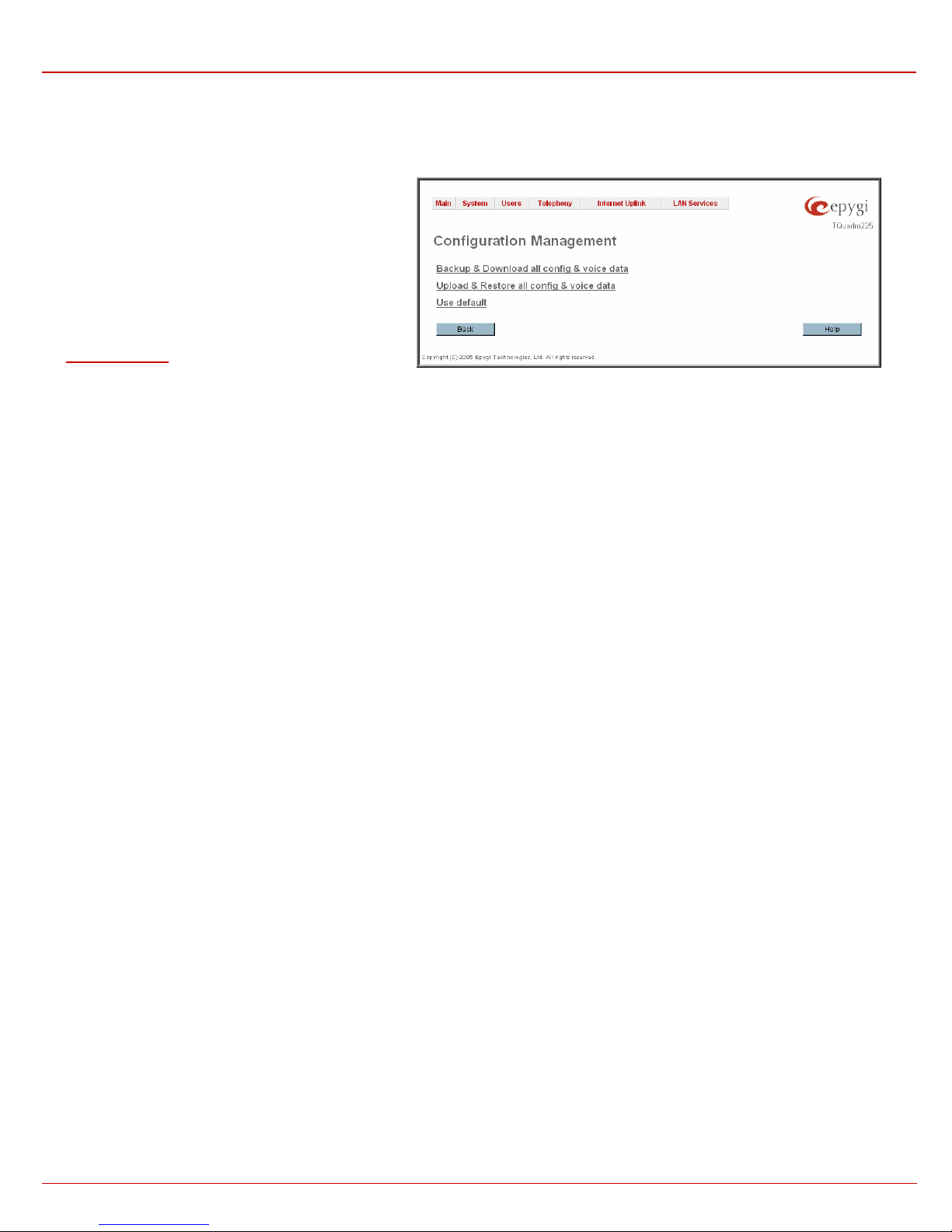
Configuration Management
The Configuration Management assists the administrator to manage the system configuration settings and voice data, i.e., to backup and
download the settings to the PC and then to upload and restore them back to the Quadro. Additionally this page gives a possibility to restore the
factory default configuration settings.
The Backup & Download all config & voice data link
generates a backup file with all configuration settings and
user uploaded greeting messages and opens a file chooser
window for immediate download to the user PC.
Attention: Configuration and voice data cannot be backed
up if the size of voice data is too large. In this case, to be
able to backup configuration and voice data on the Quadro,
please remove some user defined system messages (by
restoring the default ones, see chapter Administrators Login
at Feature Codes), or remove some extensions from the
210HUser Management table.
Fig. II-24: Configuration Management page
The Upload & Restore all c onfig & voice data link opens a page with the Browse button, (which opens a file chooser to select a backed-up file)
and a Configuration to Upload field requiring the file path to upload and to restore it immediately. Pressing Save will restore the selected backup
file, and delete all current user defined greetings and replace configuration settings.
The Use Default functional button resets all configuration settings and restores the board’s factory default configur ation. By restoring the default
configuration you will replace your current one and reboot the device. You will not be automatically redirected to the GUI start page. After the
successful reboot you will need to enter into the management and login again to access the Quadro’s configuration. A warning message will ask you
to confirm your selection before restoring the default configuration.
Please Note: Unlike the factory default settings restore procedure initialized from the Reset button on the Quadro board, this link will keep the
following data:
• Call Statistics
• Transfer Statistics
• System Events
• Feature Keys
• Device Registration state
QuadroE1/T1; (SW Version 3.0.x) 18
QuadroE1/T1 Manual II: Administrator's Guide Administrator's Graphical User Interface
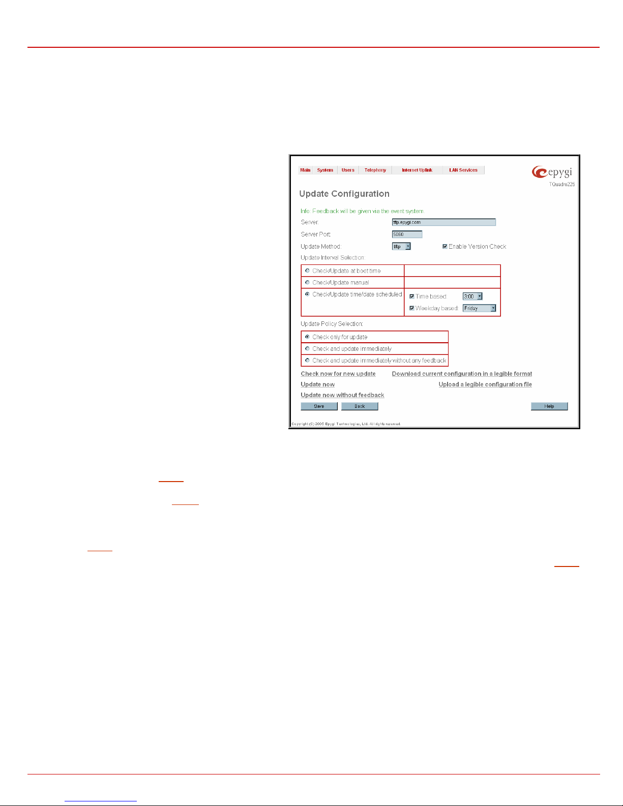
Update Configuration
The Update Configuration allows to automatically or interactively update Quadro’s configuration, as well as to download a legible and editable
configuration file, make necessary changes and upload it back to the system. This particularly allows to use parts of the configuration of one Quadro
on another Quadro with some changes done prior to uploading the new configuration. Service is mainly used by Quadro reseller, distributor, ISP or
carrier.
Attention: It is strongly recommended to consult with technical
support center before making changes on this page. Incorrect
settings here may corrupt current configuration. Page consists of
the following components:
Server and Server Port text fields require IP address or Host
name and the port number of the server configuration will be
downloaded from.
Update Method drop down list indicates the connection type
used to download the configuration (ftp, tftp, http or https).
Enable Version Check checkbox selection enabled version
verification before configuration is being downloaded.
Attention: Disabling Enable Version Check checkbox may
cause incompatibility problems on the device.
Update Interval Selection manipulation radio-button group is
used to select the frequency of configuration check/update
performed on the Quadro:
• Check/Update at boot time – with this option, new
available configuration will be checked/updated each time
after Quadro boots.
• Check/Update manually – with this option, configuration
check/upload will be performed only by manual selection.
• Check/Upda te time/da te scheduled – with this option new
available configuration will be checked/updated periodically
dependent on the selected time and/or weekday. This
selection enables Time Based and Weekday Based
checkboxes. Selecting one or both of them allows to define
the time and the weekday, when configuration check/update
will be automatically performed.
Fig. II-25: Upload Configuration page
Update Policy Selection manipulation radio-button group is used to select the operation performed on the selected:
• Check onl y for update – with this option, system will only perform checking of the availability of new suitable configuration and will log
corresponding event in the
211HEvents table (depending on configuration in Events Settings).
• Check and update immediately - with this option, system will check the availability and correspondingly update the new configuration and will
log corresponding event in the
212HEvents table (depending on configuration in Events Settings).
• Check and update immediately without any feedback - with this option, system will check the availability and correspondingly update the
new configuration but will not log any events on this.
Check now for new update functional button performs manual checking of the availability of new suitable configuration and logs corresponding
event in the
Update now functional button performs manual checking and update of the availability new configuration and logs corresponding event in the
table (depending on configuration in Events Settings).
Update now without feedback functional button performs manual checking and update of the availability new configuration and does not log any
events on this.
Download current configuration in a legible format link refers to the Configuration Summary page where necessary configuration part or a
complete configuration can be defined and downloaded or viewed.
213HEvents table (depending on configuration in Events Settings).
214HEvents
QuadroE1/T1; (SW Version 3.0.x) 19
QuadroE1/T1 Manual II: Administrator's Guide Administrator's Graphical User Interface
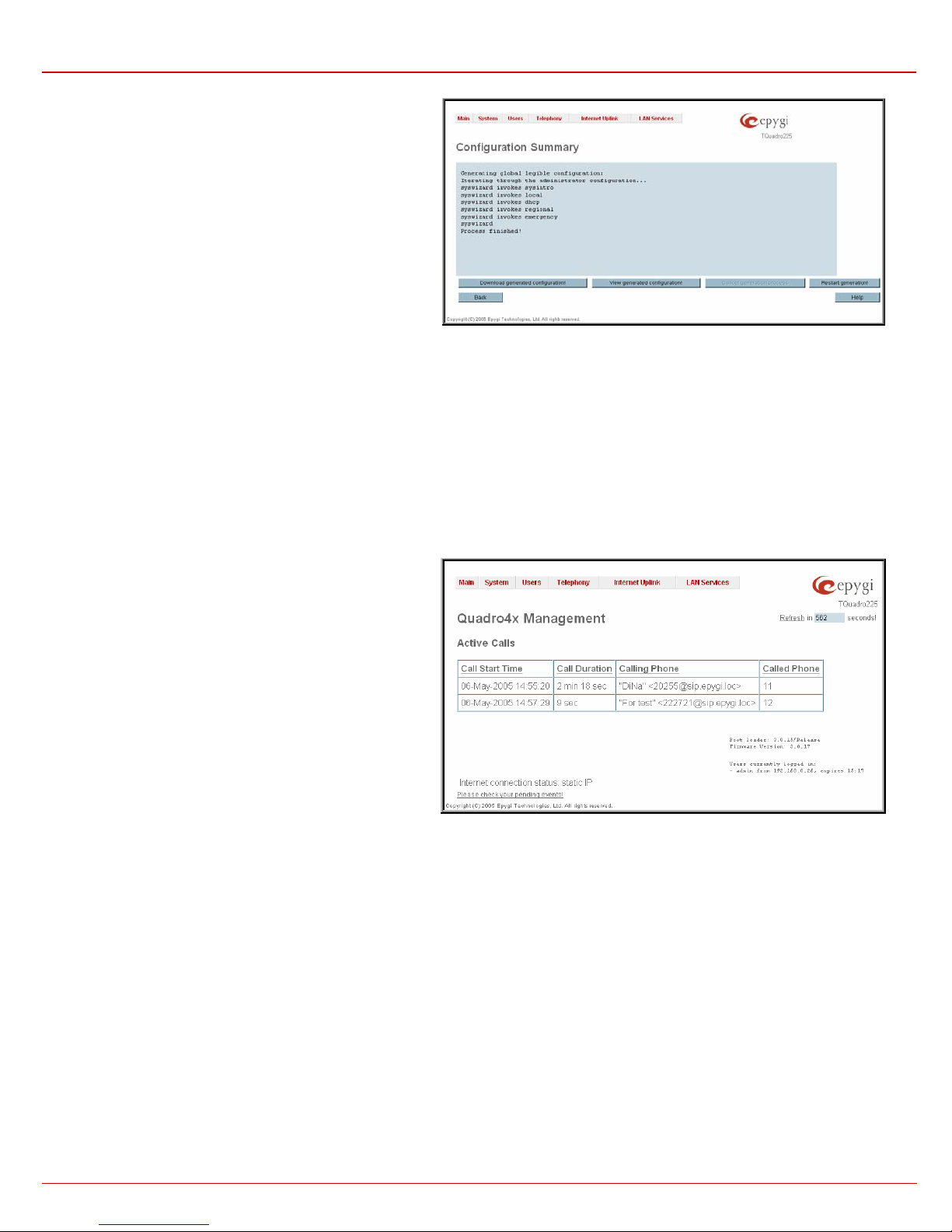
Configuration Summary page is used to define the necessary
configuration part and to download it to PC or to view it directly in
the browser.
In the text field on this page configuration part need to be
downloaded should be specified. Pressing Start generate a
legible configuration file will start parsing the configuration
structure of the device. Progress will be seen in the area below.
Cancel generation process button appears immediately
configuration generation procedure starts and is used to stop it.
Download generated configuration button becomes available
once legible configuration generation is over and is used to
download the generated file to the PC in the plain text format.
Necessary changed can be done in the downloaded
configuration file and then uploaded back to the system.
Fig. II-26: Configuration Summary page
Attention: Make sure the changes you have done in the downloaded legible configuration file are valid and will not corrupt the system when being
uploaded back to device.
View generated configuration button becomes available once legible configuration generation is over and is used to view the gene rat ed file directly
in the browser.Upload a legible configuration file link refers to the page where configuration file can be uploaded in text format. Browse button in
the opened page is used to browse the certain legible configuration file to be uploaded and updated to the system. Configuration files to be uploaded
should be in the *.txt format, otherwise system error occurs. Configuration file upload progress will be displayed in the area below.
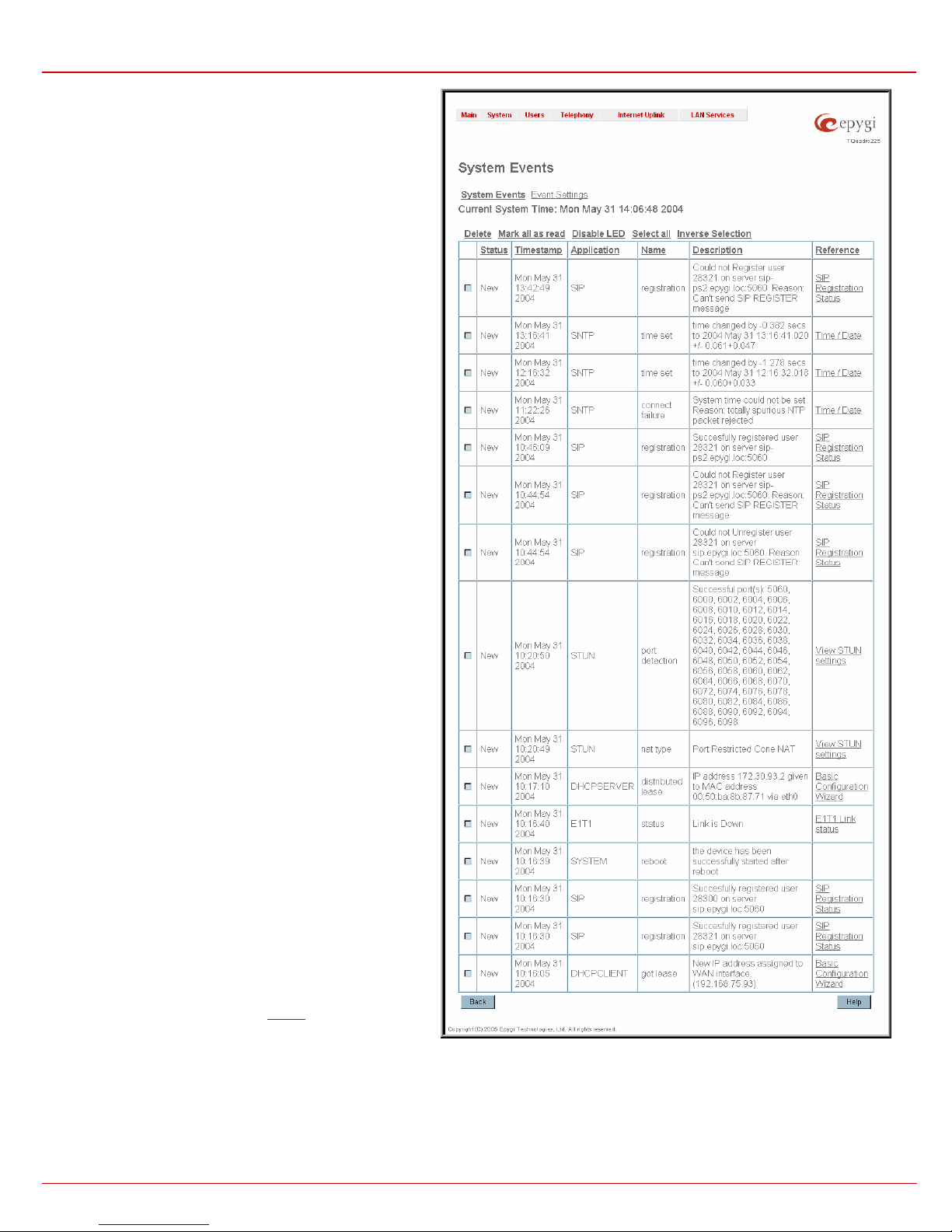
Events
The Events page shows two tables and displays all system events that have occurred in one table and event settings in the other.
The System Events page may be accessed with Events link
from the main menu. It lists information about system events that
have occurred on Quadro. When a new event takes place, a
record is added to the System Event table and a warning
“Please check your pending events!” appears at the bottom of all
management pages.
The system events and the warning message are visible only for
the administrator. The warning link, (which leads directly to the
System Events page) will disappear from the management
pages if the administrator has marked all new events as read.
Fig. II-27: Event Warning on the Main Menu page
QuadroE1/T1; (SW Version 3.0.x) 20
QuadroE1/T1 Manual II: Administrator's Guide Administrator's Graphical User Interface
The System Events table is the list of new and read system
events. The table shows the Status of the event (new or read)
as well as the name of the application the event refers to, event
description, and the date when the event was received. For
example, if the event has occurred due to incorrect mail sending
or SIP registration, corresponding links will be seen in the
Reference column of the table. There the administrator can view
the detailed log for the event that has occurred.
The System Events page offers the following components
:
Current System Time displays the local date and time on
Quadro.
Mark all as read marks newly occurred events as read.
Disable LED switches off the LED flashing (if any do flash) on
the board. A LED notification may appear (depending on the
notification type given) in the page
215HEvents settings whenever a
new event occurs.
Fig. II-28: System Events list
QuadroE1/T1; (SW Version 3.0.x) 21
QuadroE1/T1 Manual II: Administrator's Guide Administrator's Graphical User Interface
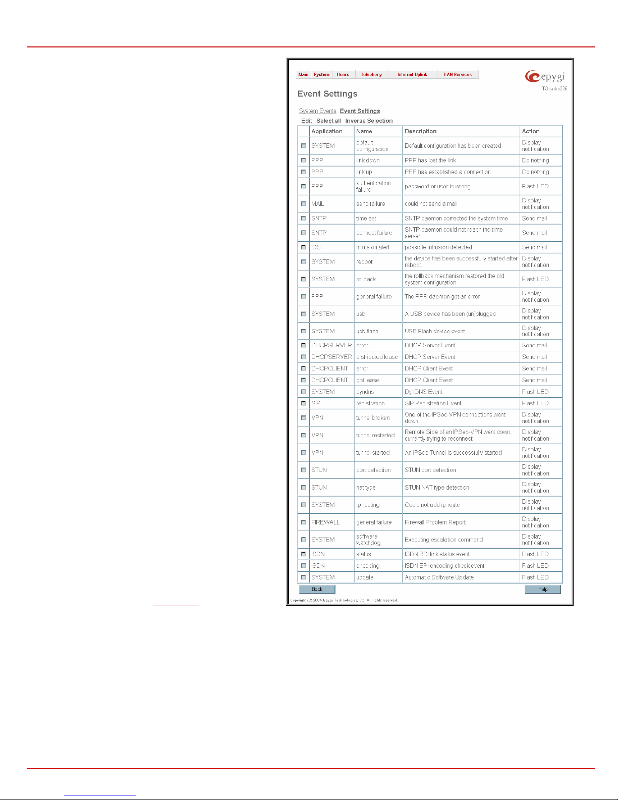
Numerous circumstances may cause a certain application on
Quadro to flag an event.
The page Event Settings lists all possible events on the Quadro
and allows controlling the way of notification (action), if one of
those events takes place.
Each entry in the events’ table has its checkbox assigned to the
row. By selecting the corresponding checkboxes, operations
such as Edit may be done for one or more events.
Edit opens the Edit Event Settings page to modify the event
action.
Do Nothing - Nothing will happen when the event occurs.
Display Notification - A notification link will be displayed on
the bottom of all pages and a record is added into the Events
table. The notification is executed as the link “Please Check
you pending events!” that leads to the page System Events.
This action also will take place if Flash LED or Send Mail has
been selected, even if not selected explicitly.
Flash LED - The second LED (yellow) will be blinking once a
second and a notification will be displayed on the bottom of all
pages. For some events the LED will start flashing after a
delay.
Send Mail - An e-mail with a notification about the new event
and an event description in the mail body will be sent to the email address specified in the
216HMail Settings page.
Fig. II-29: Event Configuration Settings page
Actions that are not allowed for the selected event (like mail notification if the PPP link is down or the mail server has been misconfigured) are
hidden. For multiple events editing, actions that do not fit at least to one of the selected events will be hidden.
If Quadro cannot get an IP address from the DHCP or PPP servers, or cannot register an extension on the SIP or Routing servers, or cannot reach
an NTP server, it raises only one event for the entire period the action has failed, but continues to try. When the required action is successful,,
Quadro raises an appropriate message.
QuadroE1/T1; (SW Version 3.0.x) 22
QuadroE1/T1 Manual II: Administrator's Guide Administrator's Graphical User Interface
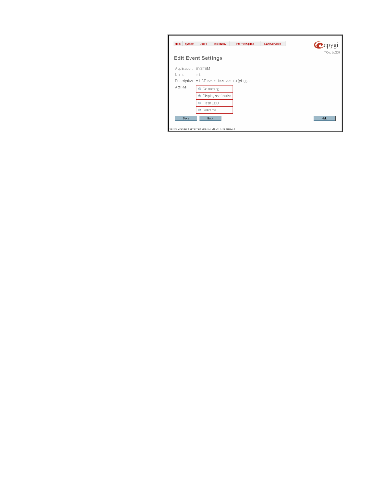
The page Edit Event Settings offers the following input
options:
Application displays the application the event refers to.
Multiple is shown here, if more than one event has been
selected for the action assignment.
Name displays the name of the event. Multiple is shown here,
if more than one event has been selected for the action
assignment.
Description displays additional information about the event.
Multiple is shown here, if more than one event has been
selected for the action assignment.
Action offers radio buttons to choose one of the actions to
notify the Quadro administrator whenever the selected event(s)
takes place.
Fig. II-30: Edit Event Settings page
To Assign an Action to the Event
1. Select the checkbox of one or more events to assign an action to them.
2. Press the Edit button. The Edit Event Settings page appears.
3. Select an action type from the Action radio buttons to notify the administrator about the event in the desired way.
4. Press the Save button to submit the changes or use Back to abort the selected action.
QuadroE1/T1; (SW Version 3.0.x) 23
QuadroE1/T1 Manual II: Administrator's Guide Administrator's Graphical User Interface
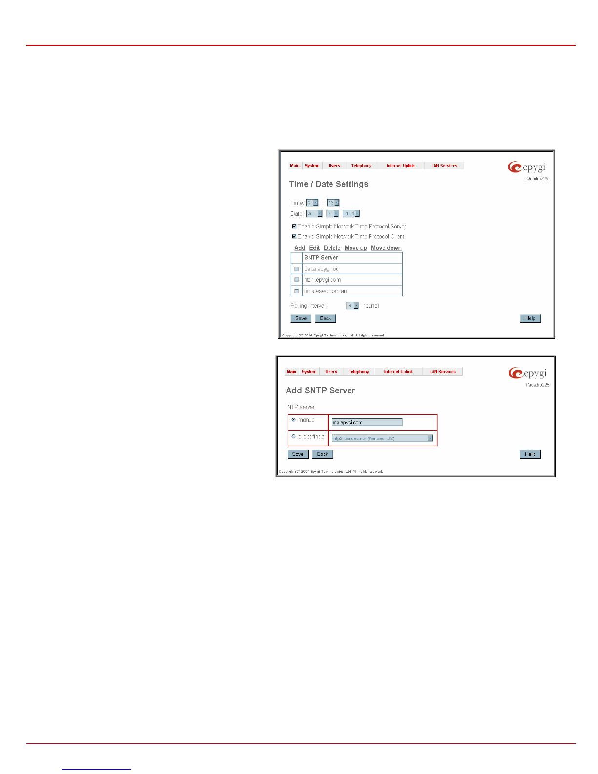
Time/Date Settings
The Time and Date Settings provide information about the current s ystem time and date. The settings may be updated through the international
time and date servers.
Time is used to set the local time (hour, minute).
Date is used to set the date (month, day, year).
Timezone provides a selection of world time zones and is used
to select the local country time zone. Timezones are specified
by GMT (Greenwich Mean Time) and by specific timezones for
the United States and Canada.
Enable Simple Network Time Protocol Server enables the
SNTP (Simple Network Time Protocol) server on Quadro, thus
Quadro becomes the timeserver for its LAN.
Enable Simple Network Time Protocol Client enables the
SNTP client on the Quadro, thus Quadro becomes a client to an
external timeserver. The checkbox disables Date and Time drop
down lists and enables the following parameters:
The SNTP Servers table lists all defined NTP Servers.
Add functional button opens an Add NTP Server page where a
new NTP server can be defined. This page offers the NTP
Server radio buttons that are used to choose between a manual
and a predefined NTP server.
Manual requires the NTP server’s FQDN (Full Qualified
Domain Name) or its IP address.
Predefined is used to select the NTP server’s host
address from the drop down list, where the most common
NTP servers are listed.
The Move Up and the Move Dow n functional buttons are used
to sort NTP servers in the order they need to be accessed. If the
NTP server on the first position in the SNTP Servers table does
not answer, NTP server on the next position will try to be
reached.
Please Note: Add another NTP server to the list if you feel
defined NTP servers are not functional, i.e., the Quadro's
date/time is not being updated automatically.
Polling Interval indicates the time interval for the periodical
synchronization between timeserver and Quadro. It counts in
hours.
Attention: Time and Date Settings will be reset if Quadro has lost power.
Fig. II-31: Time and Date Settings page
Fig. II-32: Add NTP Server page
QuadroE1/T1; (SW Version 3.0.x) 24
QuadroE1/T1 Manual II: Administrator's Guide Administrator's Graphical User Interface
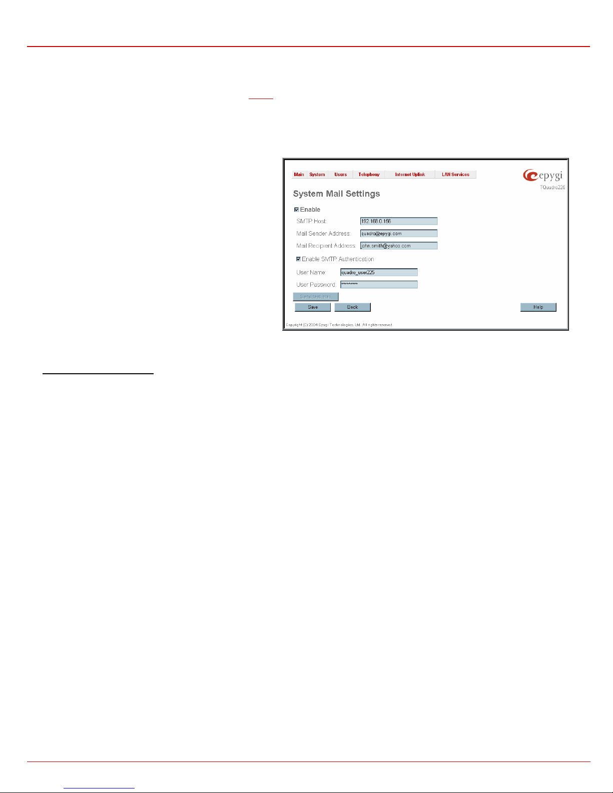
Mail Settings
The System Mail Settings page gives a possibility to send warnings automatically about the boa rd status or problems to the administrator. System
events that require email notification are selected on the
configured for voice message transmission to the extension user’s mailing account.
Enable enables the system mail sending possibility and voice
messages transmission to the extension user’s mailbox.
SMTP Host requires the SMTP host IP address or domain
name. The SMTP host needs to be configured to enable voice
message transmission.
Mail Sender Address requires the source address for the
Quadro notification emails. The email address defined here
should be an existing valid email address registered on the
selected SMTP server or should have permission to use that
particular SMTP server for emails transmission.
Mail Recipient Address requires an active email address. The
e-mail recipient here can be a Quadro administrator or someone
responsible for network and system problems.
Enable SMTP Authentication has to be selected if the
specified SMTP server requires an authentication. In this case,
authentication User Name and Passw ord configured on the
SMTP server should be defined in the corresponding text fields.
Send Test Mail is used to initiate a test e-mail transmission.
This button will be enabled if correct values have been
submitted and saved on this page.
To configure the System Mail
1. Enable the system mail sending by the Enable checkbox selection.
2. Update or set the SMTP host in the SMTP Host text field.
3. Update or set the e-mail sender address in the Mail Sender Address text field.
4. Update or set the e-mail address in the Mail Recipient Address text field.
5. Enable SMTP Authentication if it is required of the server.
6. Insert into the corresponding text fields an authentication User Name and a User Password defined by your SMTP server.
7. Press the Save button to submit these settings.
8. Use the Send Test Mail button to send a test e-mail with the configured settings.
217HEvents p age. Besides, system mail has to be enabled and the SMTP server needs to be
Fig. II-33: System Mail Settings page
QuadroE1/T1; (SW Version 3.0.x) 25

QuadroE1/T1 Manual II: Administrator's Guide Administrator's Graphical User Interface
Firmware Update
This window allows to update the software of Quadro by installing new firmware called image. Users registered at Epygi will receive a notice when
new firmware is available and will be able to download it from the Epygi Technical Support WEB page.
Updating a new firmware requires a perfectly working power supply. Therefore Quadro is provided with a battery (accumulator). If the battery is low
or simply absent the “There is no battery or voltage is low” warning is displayed
Please Note: Installing new firmware will take about 15 minutes.
During this time, the QuadroCS, telephony and Internet access
will be disabled.
The firmware update will cause the loss of the following data:
• DHCP leases
• Transfer statistics
• Call statistics
• All pending events
• User specific GUI states
• All custom (user recorded) voice messages
The following main processes will be stopped during the
firmware update and will be restarted afterwards:
• Voice Software
• Network Time Protocol Daemon
• Network Interface Statistic Daemon
Please Note: If you consider the
displayed tables to be important, it is recommended to download
them from the corresponding page prior to starting the Firmware
Update.
Next will move you to the second page of Firmware Update
where the image file should be selected.
218HCall Statistics entries in the
Fig. II-34: Firmware Update page 1
The second page of Firmware update has the Browse button
used to browse the image file, and the Specify Image text field
that will display the selected image filename.
Pressing Sa ve will start uploading the image file to the board.
The next page will be displayed, showing the result of a
verification of the image being burned.
This page displays non-editable information about the image
validity. The Image Check will display invalid if the image does
not correspond to the hardware version.
The fields Current Software Version and New Software
Version show the old software version and the version of the
new image.
This page needs a confirmation to continue image updating. If
you are sure that the image version is appropriate for your
device press Save.
QuadroE1/T1; (SW Version 3.0.x) 26
Fig. II-35: Firmware Update page 2
Fig. II-36: Firmware Check page

QuadroE1/T1 Manual II: Administrator's Guide Administrator's Graphical User Interface
Networking Tools
The Networking Tools provide the possibility to check the Internet connection.
Ping sends four ICMP (Internet Control Message Protocol) requests with a default size of 64 bytes to the destination (IP ad dress or host name)
specified in the text field Ping Target. The response times are logged, and the round trip time (the time required from being sent until being received
again) is measured. The results are displayed in the lower area of the page: The minimum and maximum round trip time and its average, the
percentage of lost and of received frames.
Traceroute checks the Internet connection by triggering the routers (hops) that are passed to reach the destination specified in the text field
Traceroute Target. Trace routing gives feedback on the routers passed by packets on the way toward the destination and the round trip delay of
packets to these routers.
Attention: No Traceroute is possible if a high priority
Firewall has been enabled (see chapter
For the purpose of tracerouting, several IP packets are sent
out. UDP (User Datagram Protocol) is used to send packets
and ICMP (Internet Control Message Protocol) is used to
receive information about the routers. In their headers, the
TTL (Time To Live) value increases from 1 to 30. When the
first IP frame is received by the first router, its IP address will
be returned in its acknowledgement
The second frame delivers the IP address of the second
router and so on and so forth. The results of Traceroute are
displayed on the lower area of the page.
Ping Target requires the destination (IP address or host
name) for the ICMP request.
The Ping button starts pinging the specified ping target.
Traceroute Target is used to enter the IP address or host
name of the destination to be trace routed.
The Traceroute button is used to process the router
triggering to check the Internet connection.
In the field below the output of the Ping or Traceroute
procedure is shown.
To Check the Internet connection
1. Specify destination address for the ICMP request in the Ping Target text field.
2. Press the Ping button to process the ICMP request.
3. Specify the destination address to trace the route.
4. Press the Traceroute button to process the router triggering.
219HFirewall and NAT).
Fig. II-37: Networking Tools page
QuadroE1/T1; (SW Version 3.0.x) 27
 Loading...