

Page 1

QuadroCS Manual II: Administrator's Guide
Edition 1, SW Release 3.0.9 and higher, August 2005
QuadroCS (SW Version 3.0.x)
Page 2

QuadroCS Manual II: Administrator's Guide
Table of Contents
Manual I: see Installation Guide
Offers a Step-by-step guide to install and configure Quadro Conference Server basically.
Manual II: Administrator's Guide
About this Administrator's Guide ............................................................................................3
QuadroCS's Graphical Interface ..............................................................................................4
Administrator’s Main Page.................................................................................................................. 4
Recurrent Buttons .............................................................................................................................. 5
Recurrent Functional Buttons of the GUI ............................................................................................ 5
Entering a SIP Addresses correctly..................................................................................................... 5
Administrator’s Menus ............................................................................................................6
System Menu ...................................................................................................................................... 6
System Configuration Wizard ..................................................................................................................................6
Status ..................................................................................................................................................................8
General Information........................................................................................................................................ 8
Network Status .............................................................................................................................................. 9
Memory Status..............................................................................................................................................11
Hardware Status ...........................................................................................................................................11
SIP Registration Status ..................................................................................................................................11
Configuration Management ...................................................................................................................................12
Change Password.................................................................................................................................................12
Events................................................................................................................................................................13
Time/Date Settings ..............................................................................................................................................15
Mail Settings .......................................................................................................................................................16
Firmware Update .................................................................................................................................................16
Networking Tools .................................................................................................................................................18
Diagnostics .........................................................................................................................................................19
Upload Language Pack..........................................................................................................................................19
Conference Management Menu......................................................................................................... 20
Conferences........................................................................................................................................................20
Conference Codecs ........................................................................................................................................24
SIP Settings........................................................................................................................................................25
RTP Settings .......................................................................................................................................................26
NAT Traversal Settings .........................................................................................................................................28
Statistics ............................................................................................................................................................31
Call Routing Table................................................................................................................................................33
Recording Common Settings .................................................................................................................................36
Mail Default Settings ............................................................................................................................................37
Network Menu .................................................................................................................................. 38
DNS Settings.......................................................................................................................................................38
DHCP Settings.....................................................................................................................................................38
Uplink Settings Menu........................................................................................................................ 39
Firewall ..............................................................................................................................................................40
Advanced Firewall Settings .............................................................................................................................40
Filtering Rules .....................................................................................................................................................41
Service Pool..................................................................................................................................................43
IP Pool .........................................................................................................................................................44
Dynamic DNS Settings..........................................................................................................................................46
Registration Form............................................................................................................................. 47
Logout .............................................................................................................................................. 47
Appendix: System Default Values..........................................................................................48
Appendix: Software License Agreement................................................................................50
Manual III: see Extension User's Guide
Explains all menus that can be accessed and configured by the conference users within the QuadroCS. Further, a list of all
available conference codes can be found there.
QuadroCS (SW Version 3.0.x)
Page 3

QuadroCS Manual II: Administrator's Guide About this Administrator's Guide
About this Administrator's Guide
The QuadroCS Manual is divided into three parts:
• Manual I: Installation Guide gives step-by-step instructions to provision the Quadro Conference Serv er and configure the conferences with the
Epygi SIP Server. After successfully configuring the Quadro, users will be able to automatically or manually initiate the call conferences between
several IP peers, deal with the active conferences and record them if needed.
• Manual II: Administrator's Guide that explains all QuadroCS management menus available for administrators only. Further it includes a list of
all System Default Values.
• Manual III: Conference User's Guide explains all menus that can be accessed and configured by the conference users within the QuadroCS.
Further a list of all available call codes can be found here.
QuadroCS's Graphical Interface introduces to the QuadroCS's graphical user interface and explains all recurrent buttons.
Administrator’s Menus explains each of the Administrator's management pages according to the menu structure shown on the main page of the
Quadro management.
Appendix: System Default Values lists all factory defaults.
Appendix: Software License Agreement includes the contract for using QuadroCS's hardware and software.
QuadroCS (SW Version 3.0.x) 3
Page 4
QuadroCS Manual II: Administrator's Guide QuadroCS's Graphical Interface
QuadroCS's Graphical Interface
Administrator’s Main Page
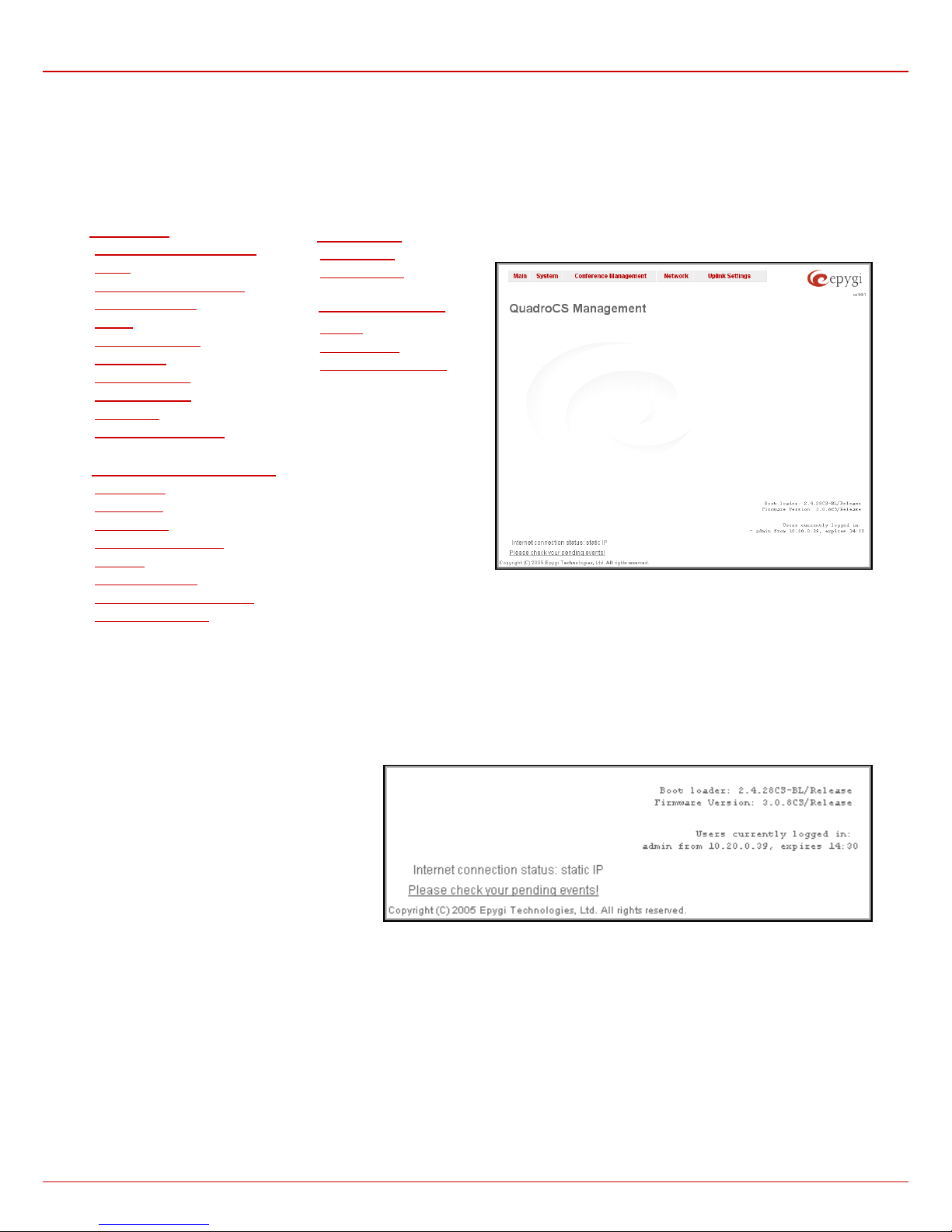
After logging in as an administrator, the QuadroCS Management page is displayed. Here the administrator may access the following settings and
perform the following actions:
1.
System Menu
• System Configuration Wizard
• Status
• Configuration Management
• Change Password
• Events
• Time/Date Settings
• Mail Settings
• Firmware Update
• Networking Tools
• Diagnostics
• Upload Language Pack
2.
Conference Management Menu
• Conferences
• SIP Settings
• RTP Settings
• NAT Traversal Settings
• Statistics
• Call Routing Table
• Recording Common Settings
• Mail Default Settings
The functional button Renew Wan IP Address appears on the administrator’s main page Quadro Conference Server Manageme nt if the Quadro
Conference Server acts as a client to a DHCP server. The button Renew WAN IP Address is used to g et a new W AN IP address, i.e., the Quadro
Conference Server moves to another network.
The button Please Check Your Pending Events will be displayed on the administrator’s main menu page if any new s ystem events exist. The link
leads to the page where these new system events are listed.
The current version of the QuadroCS's firmware and
of its boot loader is shown in the lower right corner of
the administrator’s main menu, followed by the list of
Users currently logged into the system. Information
about the IP address users accessed QuadroCS from,
the username of the logged-in user and the time until
the next automatic logout is provided here. The idle
session timeout is set to 20 minutes. If no action is
done during that time, the user automatically will be
moved to the login page and will be requested to login
again.
The Refresh link is on some pages in the lo wer right corner beside the field displaying the number of seconds left until the next refresh a nd is used
to perform a manual reload of the page.
Network Menu
3.
• DNS Settings
• DHCP Settings
4.
Uplink Settings Menu
• Firewall
• Filtering Rules
• Dynamic DNS Settings
Fig. II-1: Quadro Conference Server Administrator’s page
QuadroCS (SW Version 3.0.x) 4
Page 5
QuadroCS Manual II: Administrator's Guide Administrator's Menus
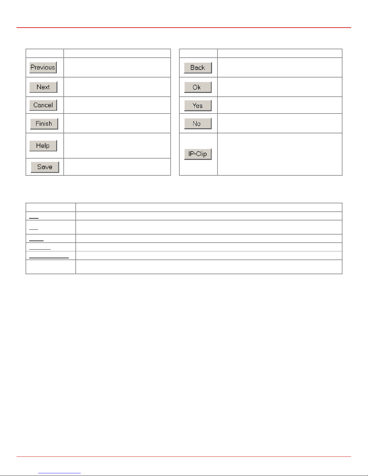
Recurrent Buttons
Button Description Button Description
This button leads back to the previous page of
a fixed sequence of pages (used mainly in
wizards).
This button leads onward to the next page of a
fixed sequence of pages (used mainly in
wizards).
This button discards the latest, not yet
confirmed entries.
This is the last button of a fixed sequence of
pages that completes and saves the entries of
the whole sequence.
This button has the same function like the "?"
in the left button bar. It opens the help page
belonging to the currently active QuadroCS
management page.
This button saves the settings modified on the
currently active management page.
This button leads back to the page you have been on
before.
This button confirms an operation you started before.
This button confirms an operation you chose before.
This button discards an operation you chose before.
This button opens a window where the last inserted IP
addresses are listed. It is a clipboard that helps the
user to make quick selection of an IP address in case it
has been already used in the past, thus to avoid typing
it again. The clipboard can hold up to 10 IP addresses,
a new IP address will replace the oldest one from the
list.
Recurrent Functional Buttons of the GUI
In connection with tables, the following buttons - among others - usually occur:
Functional Button Description
Add Allows adding a new record to the displayed table. A new page will be displayed to enter the new settings.
Edit
Delete Deletes the selected entry(s) of a table. A warning message will demand a confirmation before deleting an existing entry.
Select All Selects all table entry(s) for example for further deletion.
Inverse Selection Inverts an existing selection of table entry(s). If no entries are selected, clicking the button will select all records.
Refresh in...
Most of the tables offer the option to sort the entries in ascending or descending order by clicking the headings of the columns. A small arrow beside
the column heading will show the direction of sorting – upward or downward.
The entries of the table can be selected by the assigned checkboxes - one at a time, for the most part - in order to edit or delete them.
Allows modifying the settings of the record selected by its checkbox. Normally only one record may be selected. A new
page will be displayed to enter the modified settings.
May occur in the lower right corner of a page. It displays the number of seconds remaining until the next refresh of the
page and may be used to reload the page manually.
Entering a SIP Addresses correctly
Calls over IP are implemented based on Session Initiation Protocol (SIP) on the QuadroCS. When making a call to a destination that is somewhere
on the Internet, SIP address must be given.
SIP addresses have to be specified in one of the following formats:
“display name” <username@ipaddress:port>
“display name” <username@ipaddress>
username@ipaddress:port
username@ipaddress
The display name and the port number are optional parameters in the SIP address. If the port is not specified, 5060 will be set up as the default one.
The range of valid ports is between 1024 and 65536.
A flexible structure of wildcards is allowed. In comparison with a wildcard, the “?” character stands for only one unknown digit and the “*” character
stands for any number of any digits.
Particularly the following combinations can be used for your convenience:
QuadroCS (SW Version 3.0.x) 5
username
- *@ipaddress - any user from the specified SIP server.
- username@* - a specified user from any SIP server.
- *@* - any user from any SIP server.
Please Note: Wildcards are available for caller addresses
only. No wildcard characters are allowed for called party
addresses. To use “*” and “?” themselves (as non wildcard
characters), use “\*” and “\?” correspondingly
Page 6
QuadroCS Manual II: Administrator's Guide Administrator's Menus
Administrator’s Menus
System Menu
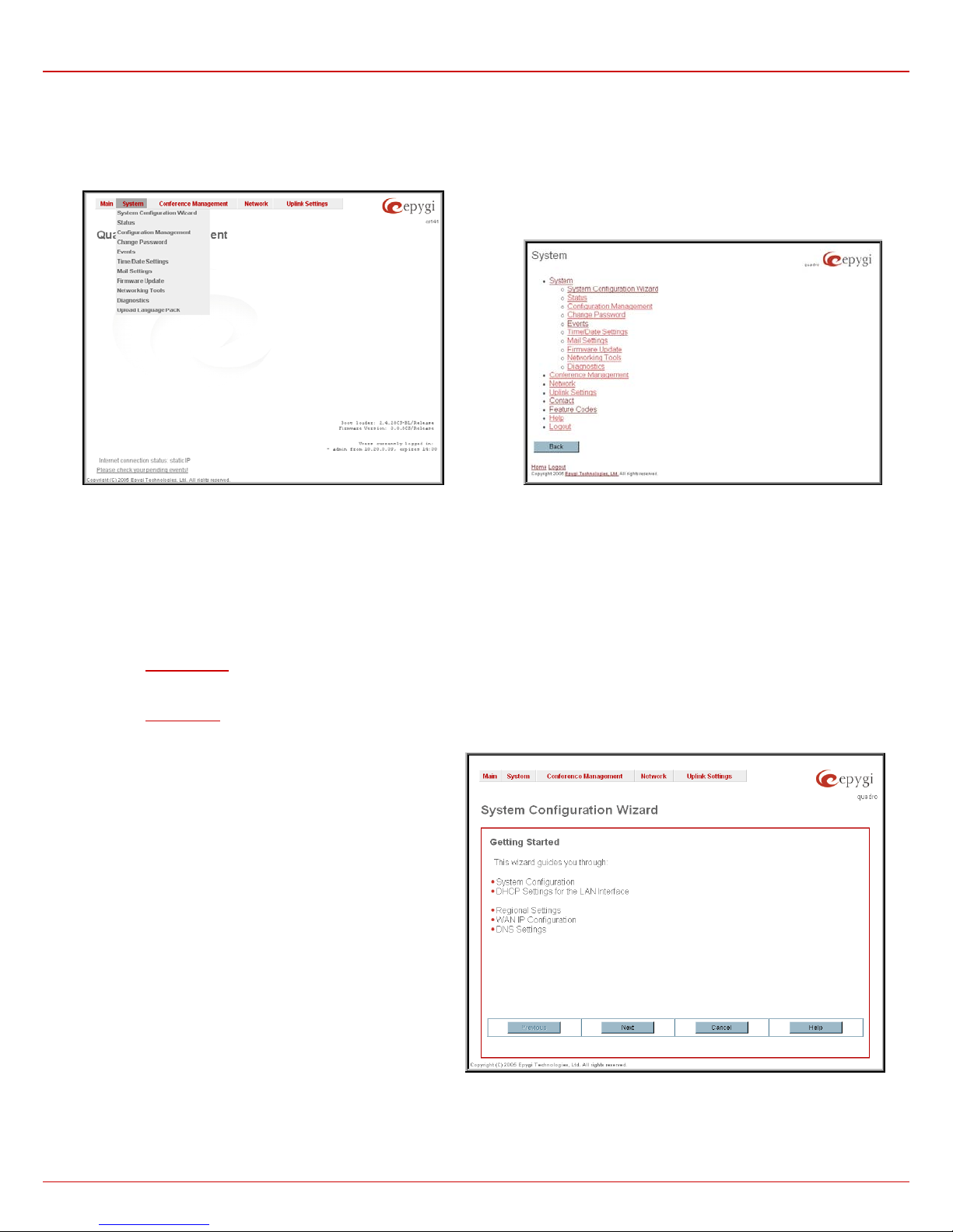
Fig. II-2: QuadroCS Management page Fig. II-3: QuadroCS Management tree
System Configuration Wizard
The System Configuration Wizard is a helpful tool for the administrator to define the Quadro Conference Server’s LAN and WAN settings, to
specify regional configuration settings and to make the Quadro operational in the global network. The System Configuration Wizard MUST be run
upon the first startup of the Quadro Conference Server. The Wizard navigates through the following basic configuration parameters and settings:
• LAN Settings
•
DHCP Settings
• Regional Settings
• WAN Settings
DNS Settings
•
For a step-by-step guide of different applications of the QuadroCS, refer to the Manual I - Installation Guide:
LAN DHCP Settings and DNS Settings are described in the chapters
below while LAN And WAN configuration settings and regional
settings will be described in this chapter.
Please Note: It is strongly recommended that factory default
settings are left unchanged if their meanings are not fully clear
to the administrator.
QuadroCS (SW Version 3.0.x) 6
Fig.0-4: System Configuration Wizard – start page
Page 7
QuadroCS Manual II: Administrator's Guide Administrator's Menus
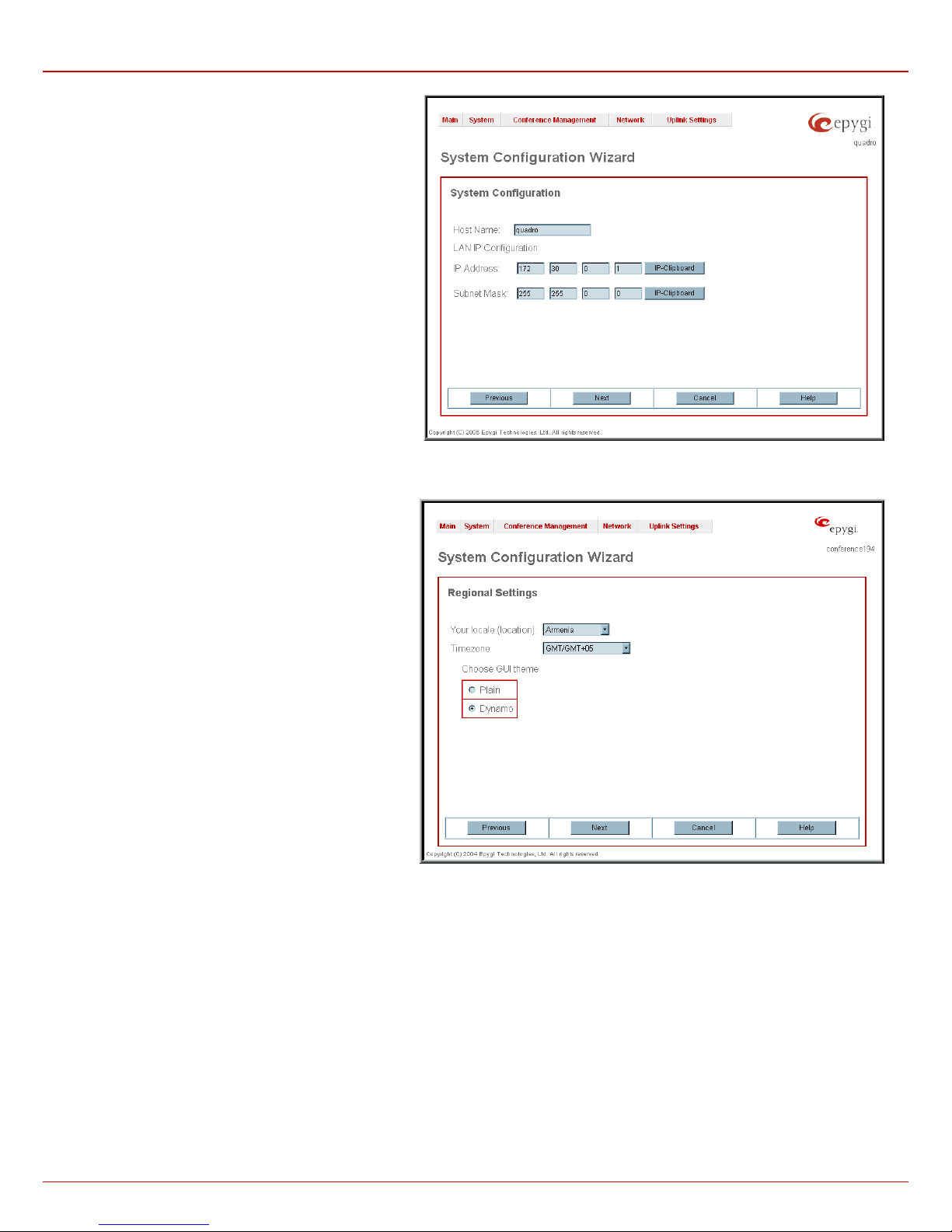
The LAN Settings page contains information about the
Quadro host name, its IP address and the subnet mask on
the LAN side. These settings make the Quadro available to
the internal network.
The System Configuration page contains of the following
components:
Host Name requires a host name for the Quadro device.
IP Address requires the Quadro host address for the LAN
interface.
Subnet Mask requires Quadro host subnet mask.
Fig.0-5: System Configuration Wizard – System Configuration page
The Regional Settings are used to select settings specific to
the location of the Quadro. This is important for the
functionality of the voice subsystem.
The Regional Settings page consists of two drop down lists
to select the Location (country) and a corresponding
Timezone and a manipulation radio button group to choose
the GUI theme of the web based configuration pages.
Fig. 1-5 System Configuration Wizard – Regional Settings page
QuadroCS (SW Version 3.0.x) 7
Page 8
QuadroCS Manual II: Administrator's Guide Administrator's Menus
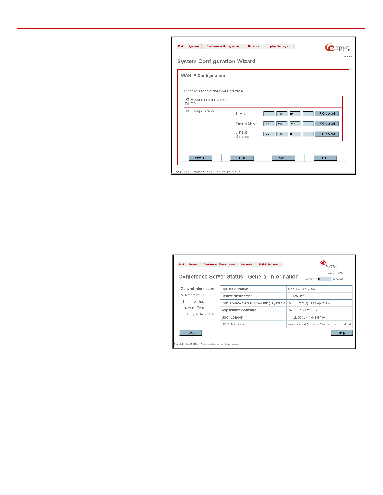
The WAN Settings page contains of the following
components:
The Assign automatically via DHCP radio button selection
switches to automatic retrieval of the WAN IP address from a
DHCP server at the ISP/uplink.
Please Note: DHCP referred to here is the one running on
the provider’s side and not the QuadroCS’s personal DHCP
server.
The Assign Manually radio button switches to the manual
adjustment of IP settings. This selection requests the
following parameters:
IP Address requires the IP address for the Quadro WAN
interface.
Subnet Mask requires the subnet mask for the Quadro
device WAN interface.
Default Gateway requires the IP address of the router all
packets are sent to, for example the IP address of the
provider's router.
Fig.0-6: System Configuration Wizard – WAN IP Configuration page
Status
The system status window displays non-editable tables providing extensive status information about QuadroCS: General Information, Network
Status
, Memory Status and SIP Registration Status. The links on this page lead to device transfer statistics, user mailboxes and supplementary
services configuration pages.
The System Status page consists of several tables providing system information.
General Information
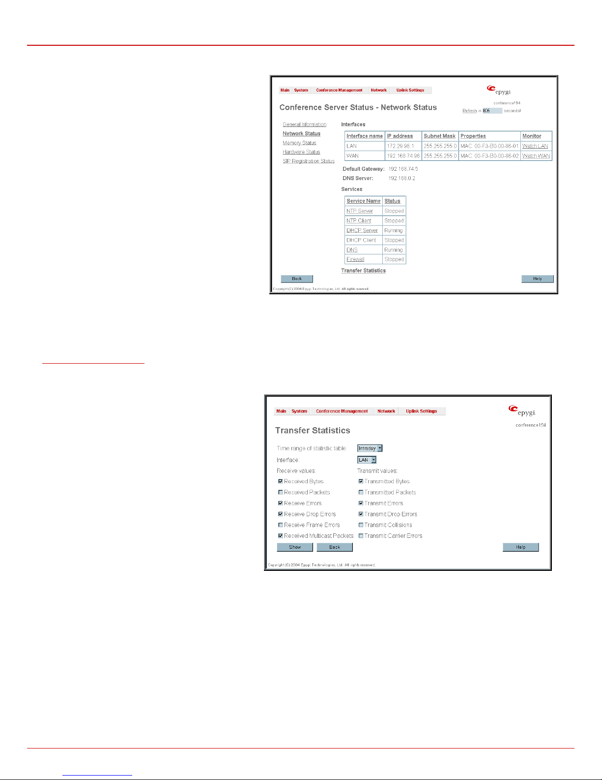
The General Information table includes the following
information:
The Uptime duration since QuadroCS's last reboot.
The Device Hostname of QuadroCS.
The Conference Server Operating System version.
The Application Software shows QuadroCS's software and
file system versions.
The Boot Loader version.
The DSP Software version and the date of build.
Fig. II-7: Quadro Status – General Information page
QuadroCS (SW Version 3.0.x) 8
Page 9
QuadroCS Manual II: Administrator's Guide Administrator's Menus
Network Status
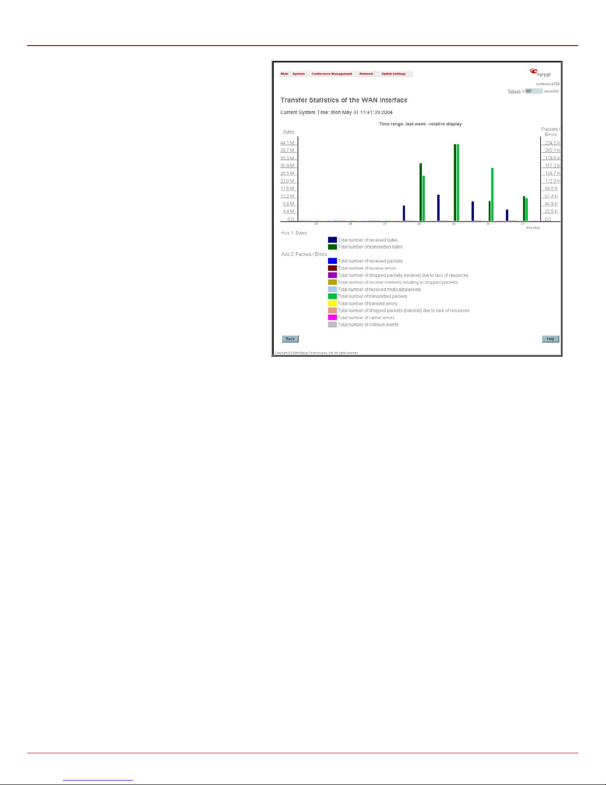
The Network Status table includes the following information
about Interfaces:
The Interface Name of the LAN and WAN interfaces
available on the QuadroCS
The IP Address corresponding to each network interface.
The Subnet Mask corresponding to each network interface.
The Mac Address corresponding to each network interface.
Monitor includes links to survey LAN and WAN traffic
correspondingly. The selection of these links will open a new
window with a table of network traffic statistics on the selected
interface:
• Received Bytes
• Received Packets
• Received Errors
• Received Drop Errors
• Received Overrun Errors
• Received MultiCast
Packets
When opening the corresponding Interface statistics window, at first, no traffic values are displayed. Then, every one minute, traffic statistics will be
updated. These tables serve as a kind of counter.
DNS Server, Alternative DNS Server and Default Gateway - displays the QuadroCS settings corres ponding to what has been configured by the
System Configuration Wizard.
Services (NTP Server and Client, DHCP Server and Client, DNS and Firewall) Status: stopped or running.
Transfer Statistics – link to the Transfer Statistics page.
• Transmitted Bytes
• Transmitted Packets
• Transmitted Errors
• Transmitted Drop Errors
• Transmitted Carrier Errors
• Transmitted Collisions
Fig. II-8: QuadroCS Status Network Status page
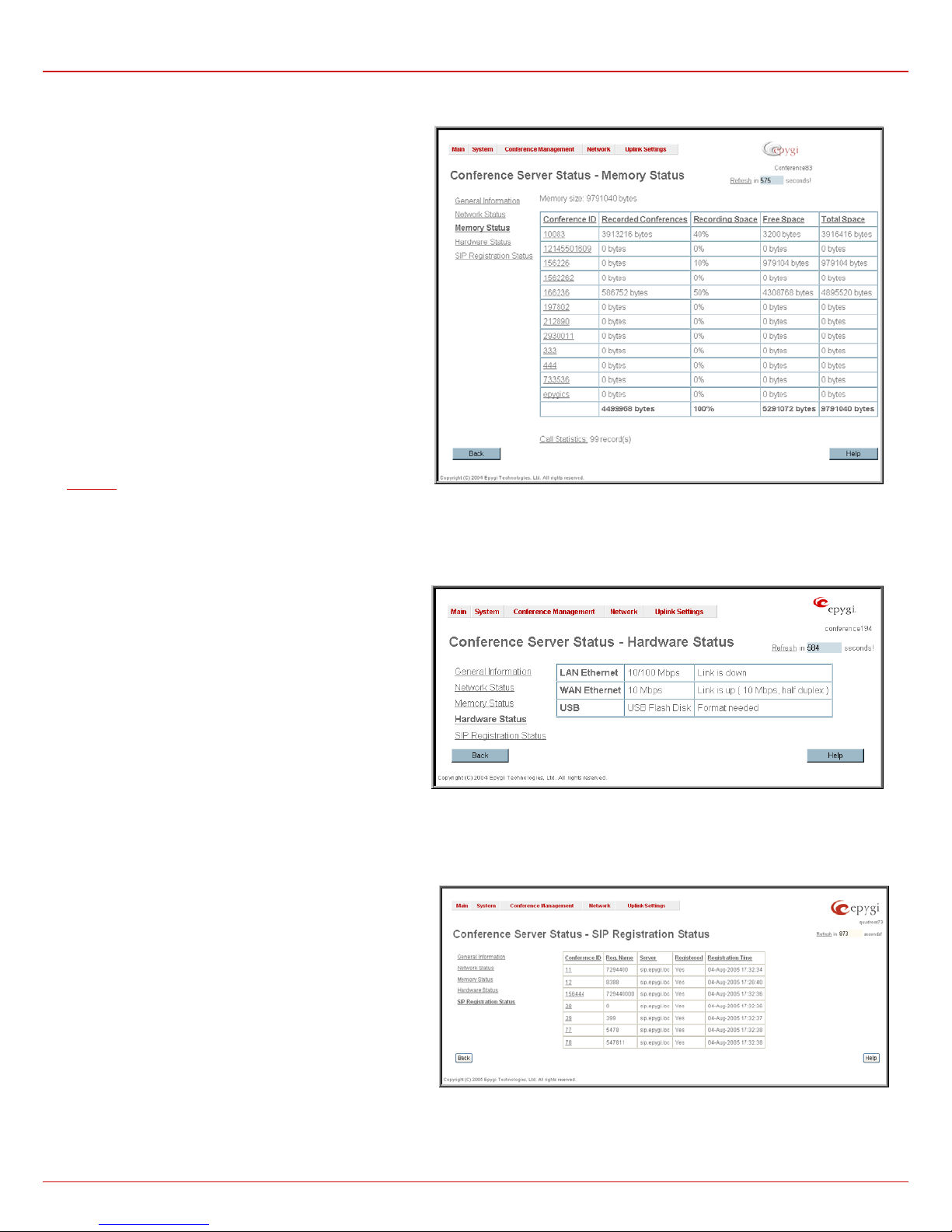
The Transfer Statistics page allows the administrator to
compose a user defined statistic table depending on the
transmit/receive value (criteria), interface type and time
period. It contains the following components:
Time Range of statistic table - the drop down list includes
the periods (days) while statistics data is to be collected and
corresponding diagram charts are to be built.
Interface - the drop down list offer the values:
WAN: Wide Area Network (WAN) events only,
LAN: Local Area Network (LAN) events only.
QuadroCS (SW Version 3.0.x) 9
Fig. II-9: Transfer Statistics page
Page 10
QuadroCS Manual II: Administrator's Guide Administrator's Menus
The area Receive Values displays the number of the
following values:
Received Bytes
Received Ethernet Packets
Received packets containing Errors
Received Drop Errors (packets that have been discarded)
Received Overrun Errors that occur when the receive
buffer is not large enough to hold all incoming packets. This
error mostly appears because of a slow receiving system
Received MultiCast Packets.
The area Transmit Values displays the number of the
following values:
Transmitted Bytes
Transmitted Ethernet Packets
Transmitted packets containing Errors
Transmitted Drop Errors (Packets that have been
discarded.)
Transmitted Carrier Errors that occur because of a
defective or lost connection on the Ethernet link
Transmitted Collisions (Transfer errors that occurred
during a simultaneous packet transmission from both sides.)
Fig. II-10: Transfer Statistics Diagram Chart
To show the Transfer Statistics Diagram Charts, select the desired criteria and click Save to create the corresponding chart.
QuadroCS (SW Version 3.0.x) 10
Page 11
QuadroCS Manual II: Administrator's Guide Administrator's Menus
Memory Status
The Memory Status page includes a table with the available
User Space information shown separately for each conference.
The table displays the space occupied by the recording
referring to the conferences and the free and total recording
spaces (counted in minutes/seconds) for every conference. The
page includes the following information:
Memory Size shows the total memory space (counted in
minutes/seconds) available on the QuadroCS and assigned to
all the conferences.
Call Statistic shows the current number of entries in the
Statistics and links to it.
Fig.0-11 Memory Status page
Hardware Status
The Hardware Status table displays a list of the hardware
devices present and currently available on the QuadroCS's
board. The hardware device version number and additional
comments about its state are indicated here.
Fig. II-12: Hardware Status page
SIP Registration Status
The SIP registration Status is a table displaying the SIP
registration status of the conferences on the QuadroCS. The
table lists all those conferences that have SIP registration
enabled, as well as conferences ID and registration name,
information about SIP registration states (Yes or No), addresses
of SIP servers where they are registered (if so), registration date
and time.
By clicking on the row heading, the table will be sorted by the
selected column. Upon sorting (ascending or descending)
arrows will be displayed close to the column heading.
Fig. II-13: SIP Registration Status page
QuadroCS (SW Version 3.0.x) 11
Page 12
QuadroCS Manual II: Administrator's Guide Administrator's Menus
Configuration Management
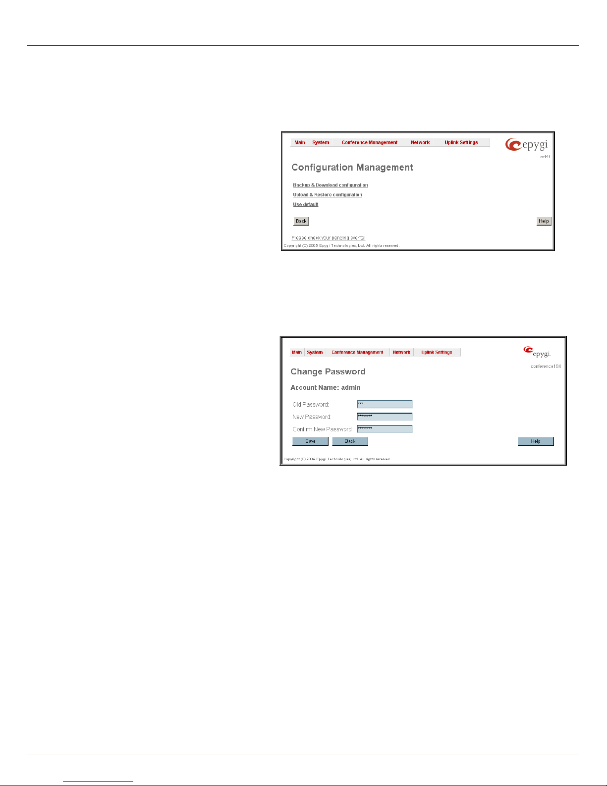
The Configuration Manage ment allows the administrator to manage the system configuration settings, i.e., to backup and download them to a PC
and then to upload and restore back to the QuadroCS. Additionally this page gives a possibility to restore the factory default configuration settings.
The Backup & Dow nload configuration link creates a backup
file with all the configuration settings and opens a file chooser
window for immediate download to the user PC.
The Upload & Restore configuration link opens a page with
the Browse button (that opens a file chooser to select a backed
up file) and a Configuration to Upload field requiring the file
path to upload and immediately restore the configuration.
Pressing Save will restore the selected backup file, erase all
recorded conferences and replace all configuration settings.
The Use Default functional button resets all configuration
settings and restores the board’s factory default configuration.
By restoring the default configuration you will replace your
current one, lose all recorded conferences and reboot the
device. You will not be automatically redirected to the GUI start
page. After the successful reboot you need to enter the
QuadroCS's management and login again to access the
QuadroCS's configuration. A warning message will ask you to
confirm your selection before restoring the default configuration.
Fig. II-14: Configuration Management. page
Change Password
The Change Password page provides information about the administrator account name and allows changing of the administrator password.
It contains the following components:
Old Password is where the current administrator password
needs to be entered. If the old password is inserted here
incorrectly, “Old Password is incorrect” error message is
displayed.
New Password is used to change the administrator's password;
the new password must be entered in this field.
Confirm New Password is used to verify the new password. If
the entered New Password does not correspond to the one in
the Confirm Password field, “The passwords do not match.
Please try again” error message is displayed.
Please Note: When reloading a former configuration, the admin
password specified here is still valid, as the admin password is
not saved with the configuration.
Fig. II-15: Change Password page
QuadroCS (SW Version 3.0.x) 12
Page 13
QuadroCS Manual II: Administrator's Guide Administrator's Menus
Events
The Events page consists of two tables and displays all system events that have occurred in one table and event settings in the other.
The System Events page may be accessed with Events link
from the main menu. It lists information about system events
that have occurred on QuadroCS. When a new event takes
place, a record is added to the System Event table and a
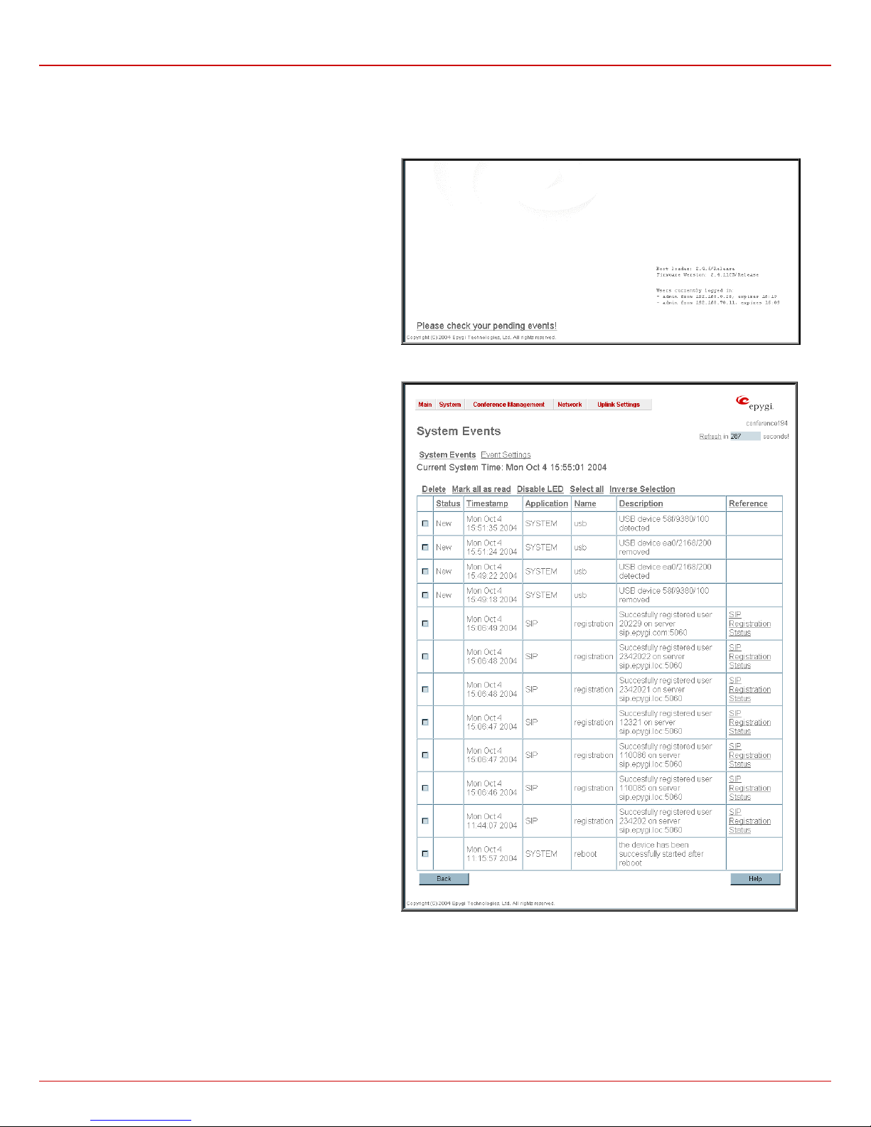
warning “Please check your pending events!” appears at the
bottom of all management pages.
The system events and the warning message are visible only for
the administrator. The warning link (that leads directly to the
System Events page) will disappear from the management
pages if the administrator has marked all new events as read.
Fig. II-16: Event warning on the main menu page
The System Events table is the list of new and read system
events. The table shows the Status of the event (new or read)
as well as the name of the application the event refers to, event
description, and the date when the event was received. For
example, if the event has occurred due to incorrect mail sending
or SIP registration, corresponding links will be seen in the
Reference column of the table. There the administrator can
view the detailed log for the event that has occurred.
The System Events page contains the following components
:
Current System Time displays the local date and time on
Quadro.
Mark all as read marks all newly occurred events as read.
Disable LED switches off the Quadro’s Info LED flashing until a
new event will take place. An LED notification may appear
depending on the notification type given in the Events page
whenever a new event occurred.
QuadroCS (SW Version 3.0.x) 13
Fig. II-17: System Events list
Page 14
QuadroCS Manual II: Administrator's Guide Administrator's Menus
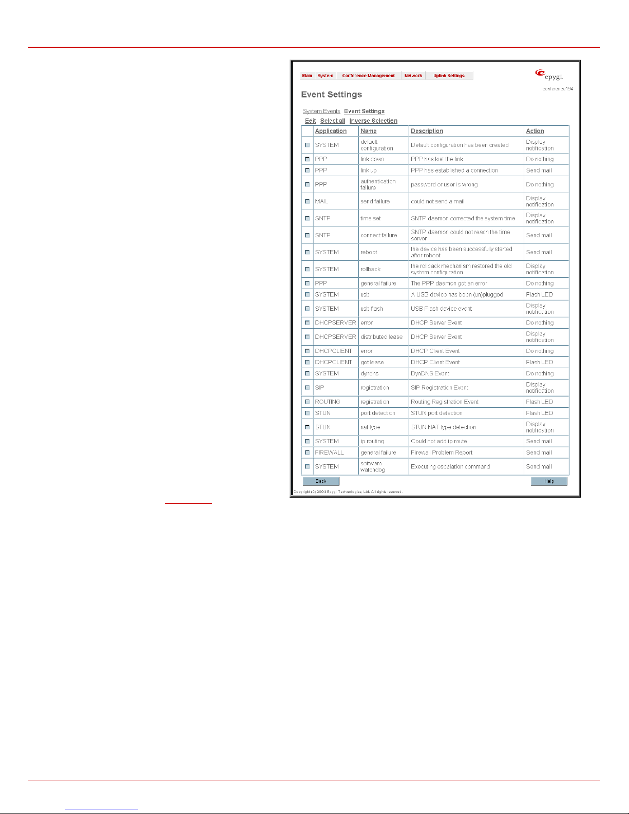
Numerous circumstances may cause a certain application on
QuadroCS to flag an event.
The page Event Settings lists all possible applications that
cause QuadroCS to raise events
and allows configuration of
notification (action), should one of these events take place.
Each entry in the events table has its checkbox assigned to the
row. By selecting the corresponding checkboxes, operations
such as Edit may be done for one or more events.
Edit opens the page Edit Event Settings to modify the event
action.
Do Nothing - Nothing will happen when the event occurs.
Display Notification - A notification link will be displayed on
the bottom of all pages and a record is added into the Events
table. The notification is executed as the link “Please Check
you pending events!” that leads to the page System Events.
This action also will take place if an action below (Flash LED
or Send Mail) has been selected, even if not selected
explicitly.
Flash LED - the second LED (yellow) will be blinking once a
second and a notification will be displayed on the bottom of all
pages. For some events the LED will start flashing after a brief
delay.
Send Mail causes sending an e-mail with a notification about
the new event and an event description in the mail body to the
e-mail address specified in the
Mail Settings page.
Fig. II-18: Event Configuration Settings page
Actions that are not allowed for the selected event (like mail notification if the link is down or the mail server has been misconfigured) are hidden. For
multiple events editing, action which does not fit at least to one of the selected events will be hidden.
If QuadroCS cannot get an IP address from the DHCP server, or cannot register an extension on the SIP or Routing servers, or cannot reach a n
NTP server, it raises only one event for the entire period the action has failed, but continues to try. When the required action is finally successful,
QuadroCS raises an appropriate event.
QuadroCS (SW Version 3.0.x) 14
Page 15
QuadroCS Manual II: Administrator's Guide Administrator's Menus
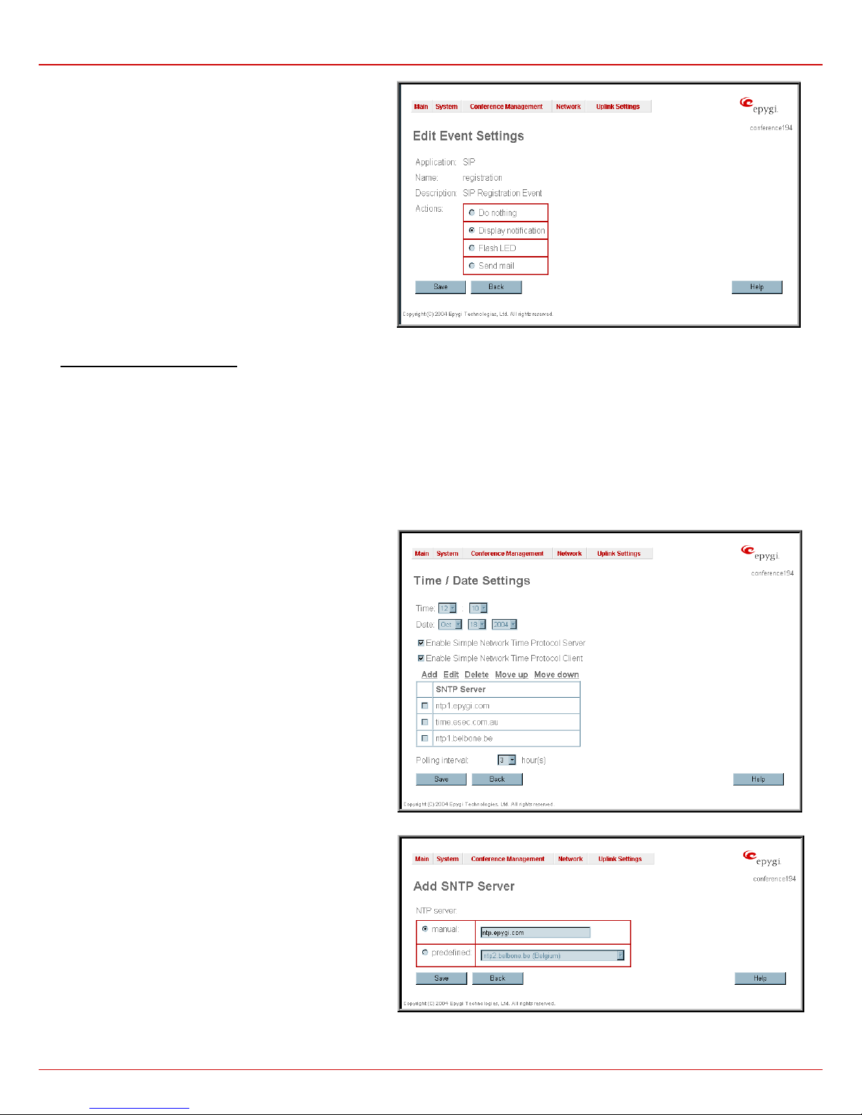
The page Edit Event Settings offers the following input options:
Application displays the application the event refers to.
Multiple is shown here, if more than one event has been
selected for the action assignment.
Name displays the name of the event. Multiple is shown here, if
more than one event has been selected for the action
assignment.
Description displays additional information about the event.
Multiple is shown here, if more than one event has been
selected for the action assignment.
Action offers radio buttons to choose one of the actions to
notify the QuadroCS's administrator whenever the selected
event(s) takes place.
Fig. II-19: Edit Event Settings page
To Assign an Action to the Event
1. Select the checkbox of one or more events to assign an action to them.
2. Press the Edit button. The Edit Event Settings page appears.
3. Select an action type from the Action radio buttons to notify the administrator about the event in the desired way.
4. Press Save to submit the changes or use Back to abort the selected action.
Time/Date Settings
Time and Date Settings provide information about the current system time and date. The settings may be updated through the international time
and date servers.
Time is used to set the local time (hour, minute).
Date is used to set the date (month, day, year).
Timezone provides a selection of world time zones and is used
to select the local country time zone. Timezones are specified
by GMT (Greenwich Mean Time) and by specific timezones for
the United States and Canada.
Enable Simple Network Time Protocol Server enables the
SNTP (Simple Network Time Protocol) server on QuadroCS,
thus QuadroCS becomes the timeserver for its LAN.
Enable Simple Network Time Protocol Client enables the
SNTP client on the QuadroCS, thus QuadroCS becomes a client
to an external timeserver. The checkbox enables the following
parameters:
The SNTP Servers table lists all defined NTP Servers.
Add opens an Add NTP Server page where new NTP server
can be defined. The page contains the NTP Server radio
buttons that are used to choose between a manual or a
predefined NTP server.
Manual requires the NTP server’s FQDN (Full Qualified
Domain Name) or its IP address.
Predefined is used to select the NTP server IP address
from the drop down list, where the most common NTP
servers are listed.
Move Up and Move Down functional buttons are used to sort
NTP servers in the order they need to be accessed. If the NTP
server on the first position in the SNTP Servers' table does not
answer, the NTP server on the next position then will try to be
reached.
Please Note: Add another NTP server to the list if you feel
defined NTP servers are not functional, i.e., the QuadroCS's
date/time is not being automatically updated.
Polling Interval indicates the time interval for the periodical
synchronization between timeserver and QuadroCS. It counts in
hours.
Attention: Time and Date Settings will be reset in case if QuadroCS has no battery or has lost power.
Fig. II-21: Time and Date Settings – Add Entry page
Fig. II-20: Time and Date Settings page
QuadroCS (SW Version 3.0.x) 15
Page 16
QuadroCS Manual II: Administrator's Guide Administrator's Menus
Mail Settings
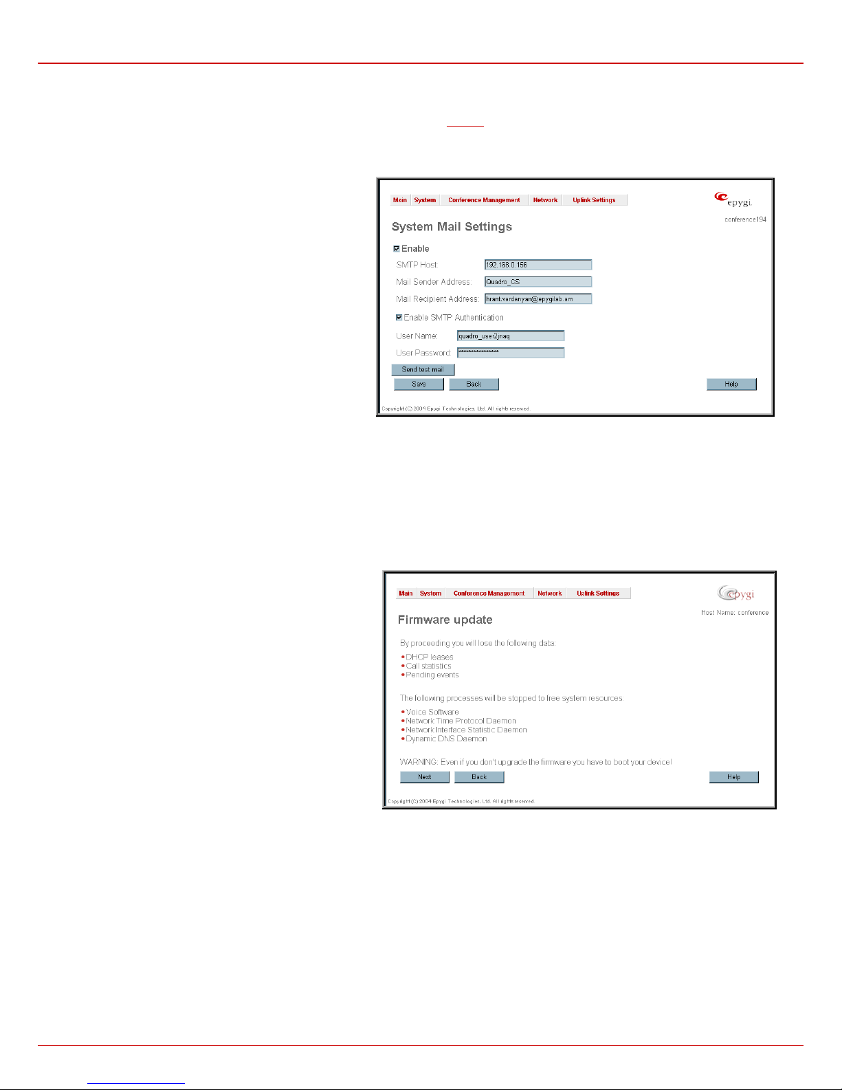
The System Mail Settings page gives the possibility of automatically sending warnings about the board status or other problems to the
administrator. System events that require email notification are selected on the
SMTP server needs to be configured for voice message transmission to the extension user’s mailing account.
Enable enables the system for sending mails and transmitting
voice messages to the extension user’s mailbox.
SMTP Host requires the SMTP host IP address or domain
name. The SMTP host needs to be configured to enable
voice message transmission.
Mail Sender Address text field requires the source address
for the Quadro notification emails. The email address defined
here should be an existing valid email address registered on
the selected SMTP server or should have permission to use
that SMTP server for emails transmission.
Mail Recipient Address requires an active email address.
The e-mail recipient here can be a Quadro administrator or
someone responsible for network and system problems.
Enable SMTP Authentication checkboxmust be selected if
the specified SMTP server requires an authentication. In this
case, authentication User Name and Password configured
on the SMTP server should be defined in the corresponding
text fields.
Send Test Mail is used to initiate a test e-mail transmission.
This button will be enabled if correct values have been
submitted and saved on this page.
Events page. The system mail functionality must be enabled and the
Fig. II-22: System Mail Settings page
Firmware Update
This window allows the software of QuadroCS to be updated by installing new firmware. Customers registered at Epygi will get notification of new
firmware and will be able to download it from the Epygi Technical Support WEB page.
QuadroCS is provided with a battery. If the battery is low or simply absent the “There is no battery or voltage is low” warning is displayed.
Please Note: Installing new firmware will last about 3 minutes.
During this time, QuadroCS won't operate, neither telephony
nor Internet access. The firmware update will cause the loss of
the following data:
The following main processes will be stopped during the
firmware update and will be restarted afterward:
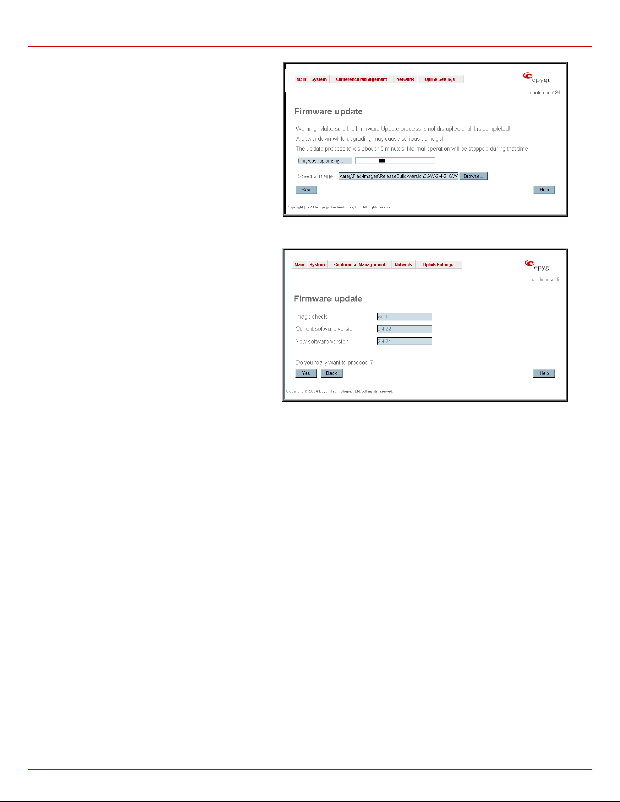
Next button will move to the second page of Firmware Update
to select the image file.
• DHCP leases
• Call Statistics
• All pending events
• Voice Software
• Network Time Protocol Daemon
• Network Interface Statistic Daemon
• Dynamic DNS Daemon
Fig. II-23: Firmware Update page 1
QuadroCS (SW Version 3.0.x) 16
Page 17
QuadroCS Manual II: Administrator's Guide Administrator's Menus
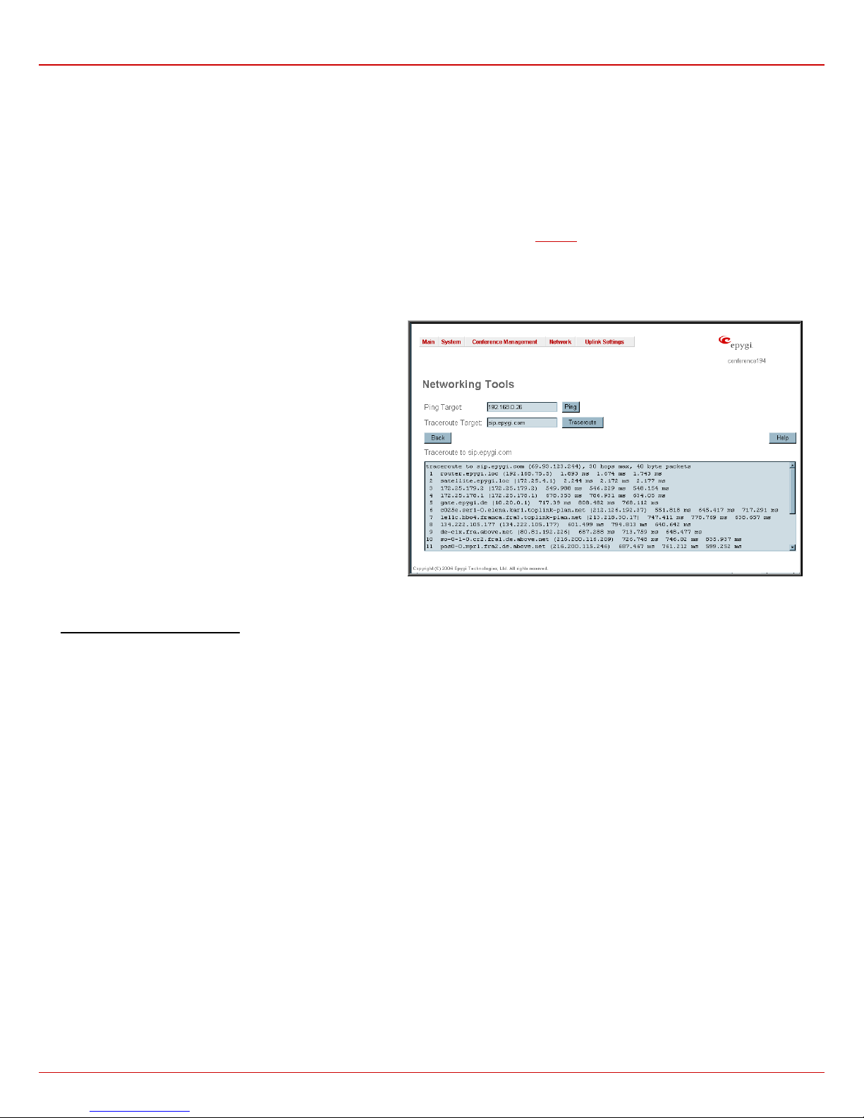
The second page of Firmware update consists of the Browse
button used to browse the image file, and the Specify Image
text field that will display the selected image filename.
Pressing Save will start uploading the image file to the board.
The next page will be displayed, showing the result of a
verification of the image being burned.
Fig. II-24 Firmware Update page 2
This page displays non-editable information about the image
validity. The Image Check will display invalid if the image does
not correspond to the hardware version.
The fields Current Software Version and New Software
Version show the old software version and the version of the
new image.
This page needs a confirmation to continue image updating. If
you are sure that the image version is appropriate for your
device press Save.
Fig. II-25: Firmware Check page
QuadroCS (SW Version 3.0.x) 17
Page 18
QuadroCS Manual II: Administrator's Guide Administrator's Menus
Networking Tools
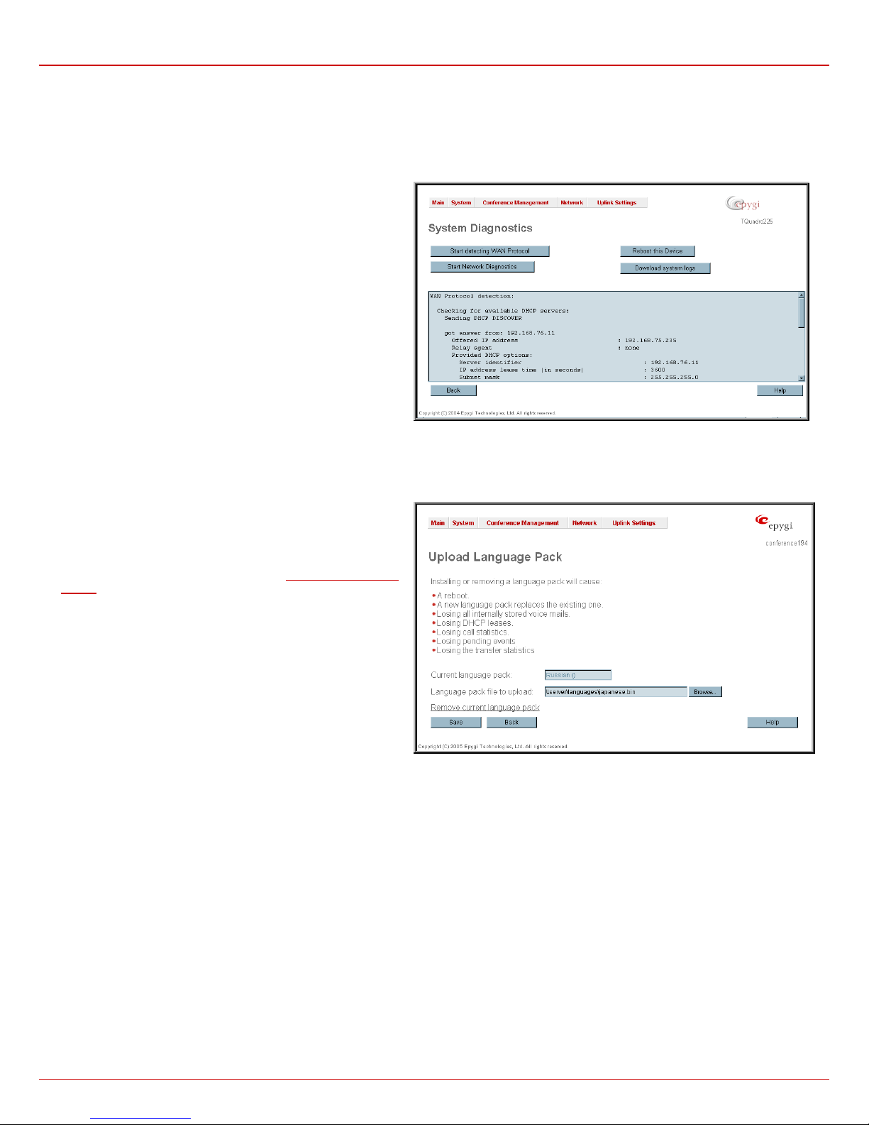
The Networking Tools provide the capability to check the Internet connection.
Ping sends four ICMP (Internet Control Message Protocol) requests with a default size of 64 bytes to the destinati on (IP address or host name)
specified in the text field Ping Target. The response times are logged, and the round trip time (the time the packet needs from being sent until being
received again) is measured. The results are displayed in the lower area of the page: The minimal and maximal round trip time a nd its average, the
percentage of lost and of received frames.
Traceroute checks the Internet connection by triggering the routers (hops) that are passed to reach the destination specified in the text field
Traceroute Target. Trace routing gives feedback on the routers passed by packets on the way toward the destination and the round trip delay of
packets to these routers.
Attention: Traceroute is not possible if a high security Firewall has been enabled (see chapter
For the purpose of tracerouting several IP packets are sent out. UDP (User Datagram Protocol) is used to send packets and ICMP (Internet Control
Message Protocol) to receive information about the routers. In their headers, the TTL (Time To Live) value increases from 1 to 30. When the first IP
frame is received by the first router, its IP address will be returned in its acknowledgement. The second frame delivers the IP address of the second
router and so on and so forth. The results of Traceroute are displayed on the lower area of the page.
Firewall).
Ping Target requires the destination (IP address or host name)
for the ICMP request.
The Ping button starts pinging the specified ping Target.
Traceroute Target is used to enter the IP address or host name
of the destination to be trace routed.
The Traceroute button is used to process the router triggering to
check the Internet connection.
To Check the Internet connection
1. Specify destination address for the ICMP request in the Ping Target text field.
2. Press the Ping button to process the ICMP request.
3. Specify the destination address to trace the route.
4. Press the Traceroute button to process the router triggering.
Fig. II-26: Networking Tools page
QuadroCS (SW Version 3.0.x) 18
Page 19
QuadroCS Manual II: Administrator's Guide Administrator's Menus
Diagnostics
The System Diagnostic page gives a possibility to run Network
and WAN protocol diagnostics, to verify QuadroCS's connectivity
and to download all system logs for possible problems recovery.
The Start Detecting WAN Protocol button is used to initiate WAN
diagnostics that will detect the WAN IP configuration: static or
through DHCP server. For static WAN IP configuration, gateway
availability is checked. When acting as a client, DHCP server’s
accessibilities are being verified.
The Star t Network Diagnostics button is used to initiate network
diagnostics, i.e., to check the WAN link and IP configuration, to
verify gateway, DNS primary and secondary (if configured) servers'
accessibilities.
The field below will display the diagnostics results and the
connectivity conditions. The system should be reconfigured if
problems occur during the diagnostics.
The Reboot this Device button is used to reboot the QuadroCS.
Please note that the session with the QuadroCS will be closed, i.e.,
the QuadroCS GUI should be newly opened and a new login will
be required afterward.
The Download system logs button is used to download all logs to
the local PC as a *.tar archive file. These logs can then be used by
the Epygi Technical Support Office to determine the problem that
had occurred on your QuadroCS.
Fig. II-27: System Diagnostic page
Upload Language Pack
Upload Language Pack page allows to upload a custom language
for GUI and Voice Messages of the QuadroCS. The language of
voice messages can be switched to the custom Language Pack
language from GUI setting page at the
. The language of the GUI session can be changed to the
Wizard
custom Language Pack language from the radio buttons on the
login page.
Uploading a Language Pack will cause the loss of the following
data:
• All internally stored voice mail
• DHCP leases
• Call statistics
• Pending events
• Transfer statistics
Please Note: Only one custom Language Pack can be uploaded
at the time. Uploading a Language Pack will remove the existing
one (if existing) and will reboot the QuadroCS.
Current Language Pack field displays a read only information about the custom language pack uploaded. When no custom language pack is
uploaded, field indicates “unknown”.
Below, there is a Language Pack File to Upload text field which displays the selected image filename. Browse button is used to browse the
custom language pack to be uploaded.
Remove Current Language Pack link is seen only when custom language pack is uploaded and is used to remove it from the system.
Pressing Save will start uploading the custom language pack to the board. The next page will be displayed, showing the result of a verification of the
language pack being uploaded and asks for confirmation to overwrite the existing custom language pack (if any).
After final confirmation, system will upload the selected custom Language Pack and will reboot.
System Configuration
Fig. II-28: Upload Language Pack page
QuadroCS (SW Version 3.0.x) 19
Page 20
QuadroCS Manual II: Administrator's Guide Administrator's Menus
Conference Management Menu
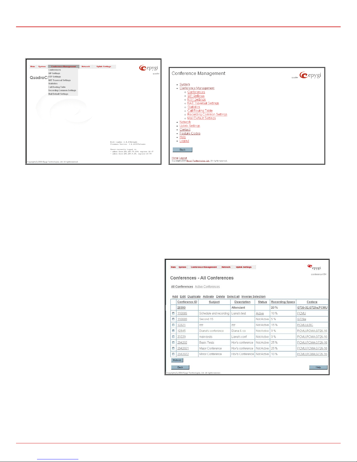
Fig. II-29: Conference Management Graphical Menu
Fig. II-30: Conference Management Tree Menu
Conferences
The Conference Management page is divided into two pages: All Conferences page where new conferences can be arranged and the Active
Conferences page to preview or to terminate the active conferences.
The Active Conferences page includes a table with all active conferences on the QuadroCS and their parameters (Conference ID, Subject,
Description, Status, Recording Space and Codecs). This page allows termination of the selected conference or monitoring of the conference
progress.
The All Conferences page includes a table that lists all created
conferences and their parameters. The table displays the
Conference ID, the conference Subject, a Description, the
actual Status, the Recording Space and the corresponding
Codecs. Each column heading in the table is created as a link.
By clicking on the column heading, the table will be sorted by
the selected column. Each record in the table has a checkbox
assigned to the row. The checkbox is used to edit, activate,
duplicate and delete the corresponding record.
Please Note: There is a 40 conference-rooms limitation on the
QuadroCS, but the amount of all participants cannot exceed 25
at the same time.
Each conference in the Conferences table has its specific voice
Codecs configured, which can be accessed and modified by
clicking on the link in the Codecs column of the corresponding
conference.
Clicking on the corresponding conference ID will link you to the
Moderator’s page where the conference properties can be
configured.
Clicking on the conference status link (which appears when
conference state is Active or Waiting), displays a page with
information on the conference. This page displays a list of
conference participants and gives an option of dropping a
participant from the conference or inviting new participants. It
also allows the moderator to start/stop/resume/pause the
conference recording and to terminate the conference.
Fig. II-31: Conference Management page
QuadroCS (SW Version 3.0.x) 20
Page 21
QuadroCS Manual II: Administrator's Guide Administrator's Menus
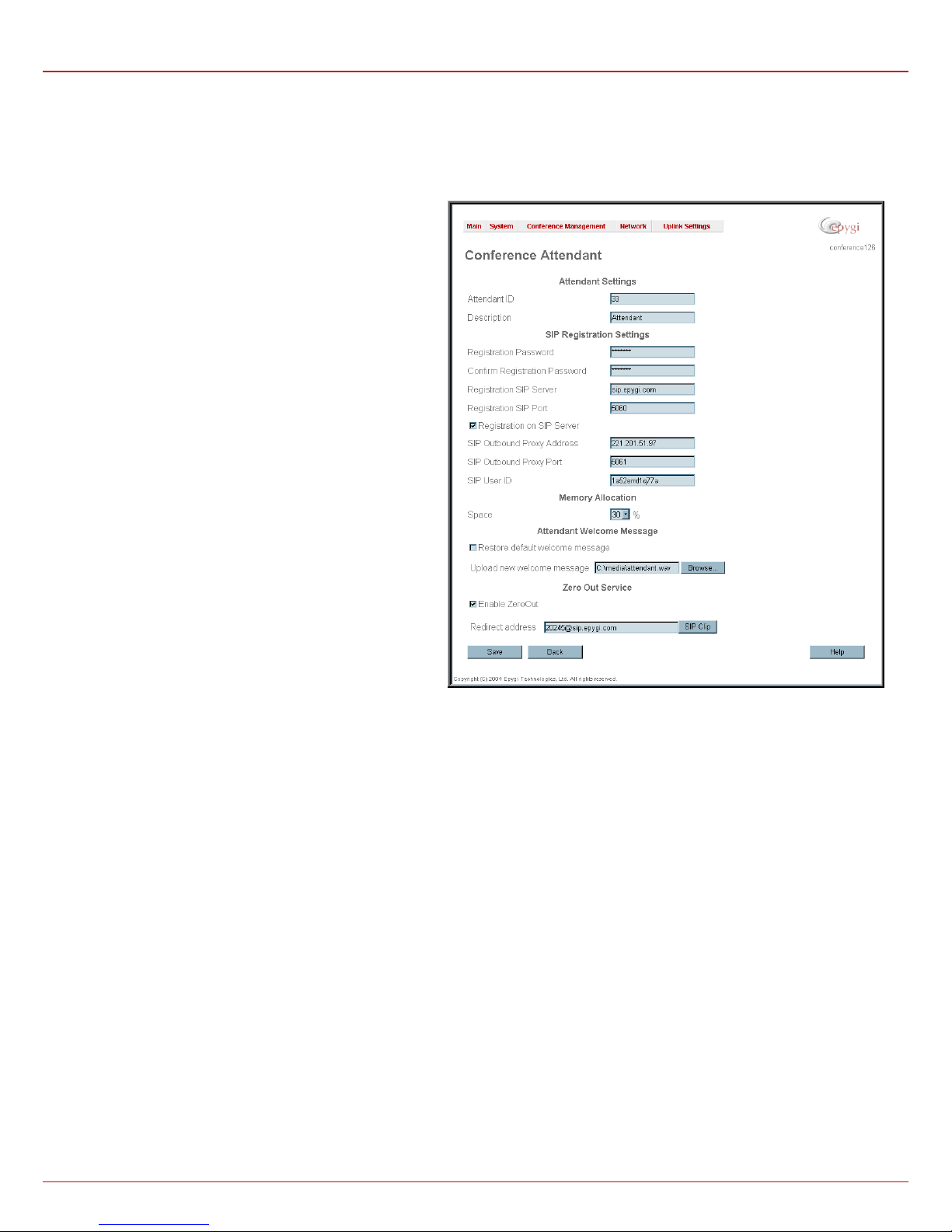
The table contains a default entry that is dedicated to the
Conference Server Auto Attendant. This entry can't be deleted but
its settings may be modified. To do so, click the corresponding
entry in the table and Edit Entry page for the Auto Attendant
page will be displayed.
The page with the Auto Attendant settings requires the
information necessary to configure the Quadro CS Auto
Attendant:
1. Attendant Settings
This group consists of the Attendant ID text field indicates a read
only information about the Conference Server’s Auto Attendant
number.
Description text field is used to insert an optional description for
the Auto Attendant.
2. SIP Registration Settings
This group requires the Auto Attendant SIP registration settings
and has the following components:
Registration User Name text field requires a user name for
conference registration on the SIP server. The registration user
name needs to be unique on the SIP server and is used to reach
the Conference Server’s Auto Attendant over the SIP network.
The Registration Password text field indicates a password for
the Auto Attendant extension registration at a SIP server.
The Confirm Registration Password text field is used to confirm
the password. If the entered password does not correspond to the
one given in the Registration Password field, the error will
appear: “The passwords do not match. Please try again”.
The Registration SIP Server text field indicates the host address
of the SIP Server. The field is not limited regarding symbol usage
and length as it can be either an IP number, e.g., 192.168.0.26 or
a host address, e.g., sip.epygi.com.
The Registration SIP Port text field indicates the Host Port
number to connect to the SIP server. It only may consist of
numerics, otherwise the error message “SIP Server Port is
incorrect” will be displayed when attempting to save the SIP
Registration Settings. If no SIP server port is specified, Quadro
will access the SIP server through its default port 5060.
The Registration on SIP Server checkbox enables the SIP
server registration option for the Auto Attendant.
Fig. II-32: User Management - Auto Attendant Settings
SIP Outbound Proxy Address and SIP Outbound Proxy Port text fields require the settings of the SIP Outbound Proxy server which acts as a
SIP server where all the SIP requests and other SIP messages are transferred. Some SIP servers use outbound proxy server to escape restrictions
of NAT. e.g. Free World Dialup service uses Outbound Proxy server. If an Outbound proxy is specified here, all SIP calls originated from the
Conference Server’s Auto Attendant are made through that outbound proxy, i.e. all requests are sent to that outbound proxy.
The UserID text field requires an identification parameter to reach the SIP server. It should be provided by the SIP service provider and can be
requested for some SIP servers only, for others field should be left empty.
3. Memory Allocation
This group includes only a drop down list that is used to specify the User Space (counted in percent) for the Auto Attendant welcome messages.
The maximum value in the drop down list is equal to the maximal available space for voice messages on the Quadro. When decreasing the Auto
Attendant memory space, the system will check for the presence of custom Auto Attendant welcome messages. If the memory required for the
welcome messages exceed the defined memory size, the system will suggest either to remove the welcome message or to select a larger size so
that the existing welcome messages can be stored there.
4. Attendant Welcome Message
This group allows updating of the active Auto Attendant welcome message, downloading it to the PC, or restoring the default one. Th e group offers
the following components:
The Restore Default Welcome Message checkbox allows restoring the Auto Attendant default welcome message file if another one has been
previously selected. If the checkbox is selected, the file upload will be disabled.
Upload new welcome message indicates the file name used to upload a new welcome message. The uploaded file needs to be in PCMU wave
format, otherwise the system will prevent uploading it with the “Invalid audio file, or format is not supported” warning message. Th e system also
prevents uploading if there is not enough memory available for the corresponding extension, which will cause the “You do not ha ve enough space”
warning.
Browse opens the file chooser window to browse for a new welcome message file.
The Download Welcome Message File link appears only if a file has been previously uploaded. The link is used to download the audio file to the
PC and opens the file chooser window where the saving location can be specified.
QuadroCS (SW Version 3.0.x) 21
Page 22
QuadroCS Manual II: Administrator's Guide Administrator's Menus
5. Zero Out Service
Enable Zero Out checkbox enables Zero Out Service which provides a possibility to caller that has reached the Conference Server’s Auto
Attendant Zero Out menu (see Call Codes) to accelerate the automatic redirection feature. Entering Zero Out menu will automatically redirect call to
the destination defined in the Redirect Address text field. If Zero Out Service is disabled, corresponding menu will be hidden in the Auto Attendant.
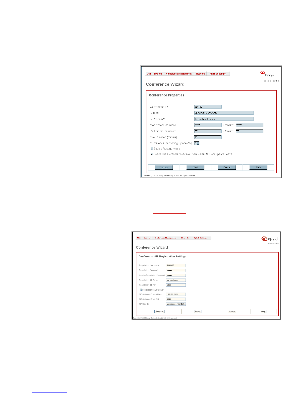
Add opens the Conference Wizard used to guide the user through the basic settings to create a new conference. The Conference Wizard consists
of two pages – for providing general conference properties and SIP registration settings. The following settings are entered into the first page of the
Conference Wizard:
Conference ID is used to enter a unique ID for the call
conference. This ID will be also used in Conference Server's
Auto Attendant to reach the local conference. Digits allowed
only. System prevents adding a conference starting with 0 digit.
Subject is an optional parameter where a brief subject of the
conference can be entered.
Description is an optional parameter used to insert additional
information about the conference.
Moderator Password can be entered to provide moderator
access to the conference. It has to be entered twice for
confirmation. The password inserted here will be used by the
moderator to join the conference. The moderator can dial codes
during the active conference as well as access conference
specific GUI pages to control the conference (view/change
conference properties, activate/deactivate it, start/stop/resume
record, view conference statistics).
Participant Password can be entered to require a password for
participant access to the conference. It has to be entered twice
for confirmation. The password entered here should be used by
the participant to join the conference. The participant can
participate in the conference only according to the rights
(speaker or listener) granted by the moderator. The participant
also can access the conference specific GUI to view the
conference properties and the other participants.
Fig. II-33: Conference Wizard - page1
Max. Duration sets the conference to be limited to a maximum duration (in minutes). Leave the field empty for unlimited conference duration.
Conference Recording Space is used to select the percentage of total QuadroCS's memory space that can be used for recording of this
conference.
Enable Routing Mode checkbox enables direct access to the Quadro’s internal routing tables when dialing out to a participant during a conference.
When this checkbox is selected, any dialed number will be parsed through
Call Routing Table.
Leave Active checkbox will keep conference active, even if all participants have left it.
The second page of the Conference Wizard is where the
SIP registration settings are configured:
Registration User Name text field requires a user name
for conference registration on the SIP server. The
registration user name needs to be unique on the SIP
server and is used to reach the conference over the SIP
network.
Registration Password is the password for the
registration on the SIP server. It must be confirmed in the
Confirm Registration Password text field.
Registration SIP Server indicates the host address of the
SIP server. The field is not limited regarding symbol usage
and length. It can be either an IP address (ex:
192.168.0.26) or a host address (ex: sip.epygi.com).
Registration SIP Port indicates the host port number to
connect to the SIP server. The SIP server port may only
contain digit values. If the SIP server port is not specified,
the QuadroCS will access the SIP server through the
default port of 5060.
Registration on SIP Server enables the conference ID to
be registered on the SIP server.
Fig. II-34: Conference Wizard - page2
SIP Outbound Proxy Settings are optional settings used for the QuadroCS’s connection to the SIP server. The SIP Outbound proxy is a SIP server
where all the SIP requests and other SIP messages are transferred. Some SIP servers use outbound proxy servers to avoid the restrictions of NAT.
SIP Outbound Settings are provided by the SIP server provider and are used by QuadroCS to reach the selected SIP server. If an Outbound proxy
is specified for a conference, all outbound SIP calls are made through that outbound proxy.
SIP Outbound Proxy address requires the IP address or the host name of the outbound proxy.
SIP Outbound Proxy Port requires the port number on which QuadroCS may reach the outbound proxy.
SIP UserID requires a user ID to for authentication on the SIP server. The UserID may be requested by some SIP servers. If not required,
the field should be left blank.
QuadroCS (SW Version 3.0.x) 22
Page 23

QuadroCS Manual II: Administrator's Guide Administrator's Menus
Duplicate is used to generate a new conference with the settings of an exiting one. To use the Duplicate button only one record may be selected.
The Duplicate button opens the Conference Wizard where some of the basic settings of the selected conference are alrea dy filled in. Basic
settings for the new conference (like password or username) will still be required.
Activate is used to activate the selected conference(s).
To Add a Conference
1. Press the Add button on the Conferences page. The Conference Wizard appears in the browser window.
2. Enter the desired conference number in the Conference ID text field.
3. Define the conference Subject and Description in the corresponding text fields if needed.
4. Define the Moderator and Participant Passwords and confirm them.
5. Define the conference Max. Duration in the corresponding text field.
6. Choose a Recording Space from the homonymous drop down list to assign a percentage of memory to the corresponding conference.
7. Enable Leave Active checkbox for the conference to remain active even when all participants have left.
8. Press Next to move to the conference SIP Registration Settings configuration page.
9. Provide the SIP Registration Password and confirm it in the corresponding text fields.
10. Define the Registration SIP Server and SIP Port in the corresponding text fields.
11. Provide SIP Outbound Proxy Address, SIP Outbound Proxy Port and SIP User ID if needed.
12. Press Finish to arrange the conference with the defined settings.
To Delete a Conference
1. To remove a conference and its settings select one or more checkboxes of the corresponding conferences that should be deleted from the
Conference Management table. Press Select all if all the conferences should be deleted.
2. Click the Delete button on the Conference Management page.
3. Confirm the deletion by clicking Yes. The conference will then be deleted. To abort the deletion and keep the conference in the list, click No.
QuadroCS (SW Version 3.0.x) 23
Page 24
QuadroCS Manual II: Administrator's Guide Administrator's Menus
Conference Codecs
To establish IP voice communication, both parties have to use the same codec. During setup of the communication line, the codec is negotiated. If
the caller does not find a matching codec, the communication won’t start. If you want to be reachable by all IP callers, it is helpful to support as many
codecs as possible. In this case, all codecs that Quadro supports should be added to the Active Codecs' table. On the other hand, some codecs
require significant bandwidth- up to 64 kBit/s. If you definitely don't want to use these codecs, you must remove them from the Active Codecs' table.
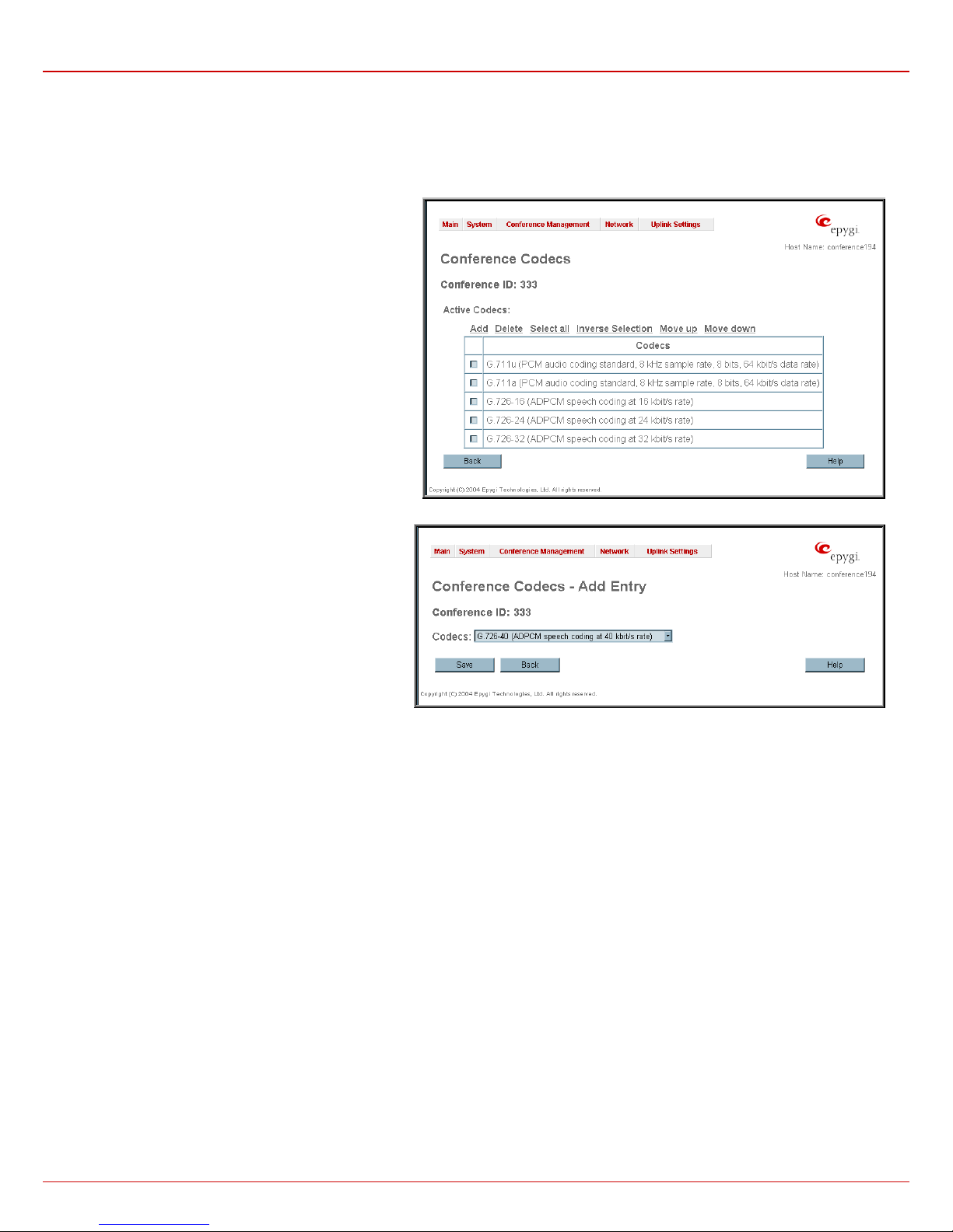
The Conference Codecs page displays a list of Quadro
Active Codecs.
The table Active Codecs lists active voice codecs for the
selected line that are supported by Quadro. The order of
records in the Active Codecs' table is important for
transmitting and receiving. A codec placed at the top of the
table will be used as the preferred codec. If the remote
party does not support the preferred codec, the following
codecs will be tried out strictly in the top down order given
in the Active Codecs' table.
Each record in the table has an assigned checkbox. It is
used to select the record to be deleted or moved up or
down. The following error message results if no records are
selected and the user activates the delete button:
records selected”. At least one codec must be attached to
the line, when attempting to delete the last one the error will
occur: “At least one codec should stay in the codec list”.
“No
Fig. 0-35 Conference Codecs List
Add opens the Add Entry page where the user may add
codecs supported by QuadroCS. The voice codec defines
the voice compression algorithm for the incoming and
outgoing DSP packages.
Codecs lists all codecs supported by Quadro. If no more
codecs are available (all available codecs have already
been transferred to the Active Codecs' table), the Add
Entry page will display the message “No Available Codecs”
instead of the drop down menu.
The Move Up/Move Down buttons are used to move the
selected codec one level up or down in the table.
Fig.0-36 Conference Codecs – Add Codec page
QuadroCS (SW Version 3.0.x) 24
Page 25
QuadroCS Manual II: Administrator's Guide Administrator's Menus
SIP Settings
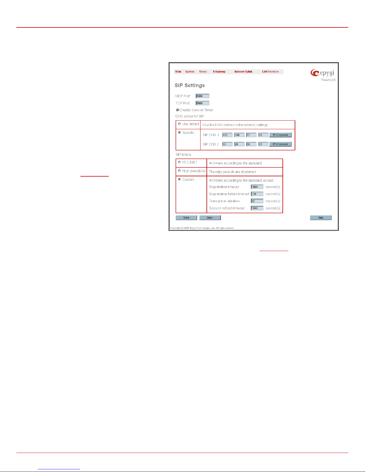
The SIP Settings provide information on the SIP receive UDP and TCP ports and allows to select DNS server configuration for SIP and SIP timers
scheme.
UDP Port indicates the SIP UDP (User Datagram Protocol)
receive port number. By default 5060 is selected and used. The
SIP UDP port cannot be in the selected RTP/RTCP port range
for FXS and IP lines (see RTP Settings
port for SIP shouldn’t be in RTP port range” error appears.
TCP Port indicates the SIP TCP (Transmission Control
Protocol) receive port number. By default 5060 is selected and
used.
Please Note: Quadro will not use TCP protocol as a transport
for SIP messages if the TCP Port field is left empty.
Enable Session Timer enables advanced mechanisms for
connection activity checking. This option allows both user
agents and proxies to determine if the SIP session is still active.
The DNS server for SIP radio button group allows to choose between regular DNS servers configured in the DNS Settings page and specific DNS
servers for the SIP traffic.
• Use default is used to apply regular DNS servers for the SIP traffic.
• Specific is used to enable SIP specific DNS servers. For this selection, both primary and secondary SIP DNS servers should be defined in the
SIP DNS 1 and SIP DNS 2 text fields. At the least, a primary DNS server should be inserted.
The SIP Timers radio button group is used to define the timeouts of the SIP messages retransmission.
• RFC 3261 will apply standard SIP timers described in the corresponding specification.
• High availability will apply SIP timers to shorten the call establishment, registration confirmation and registration failure procedures. This
selection provides more firmness to the SIP connection but increases the network traffic on the Quadro.
• Custom allows defining manually the Registration Timeout, Registration Failure Timeout, Transaction Duration and Session refresh
timeout SIP timers (in seconds).
), otherwise the “Mapped
Fig. II-37: SIP Settings page
QuadroCS (SW Version 3.0.x) 25
Page 26
QuadroCS Manual II: Administrator's Guide Administrator's Menus
RTP Settings
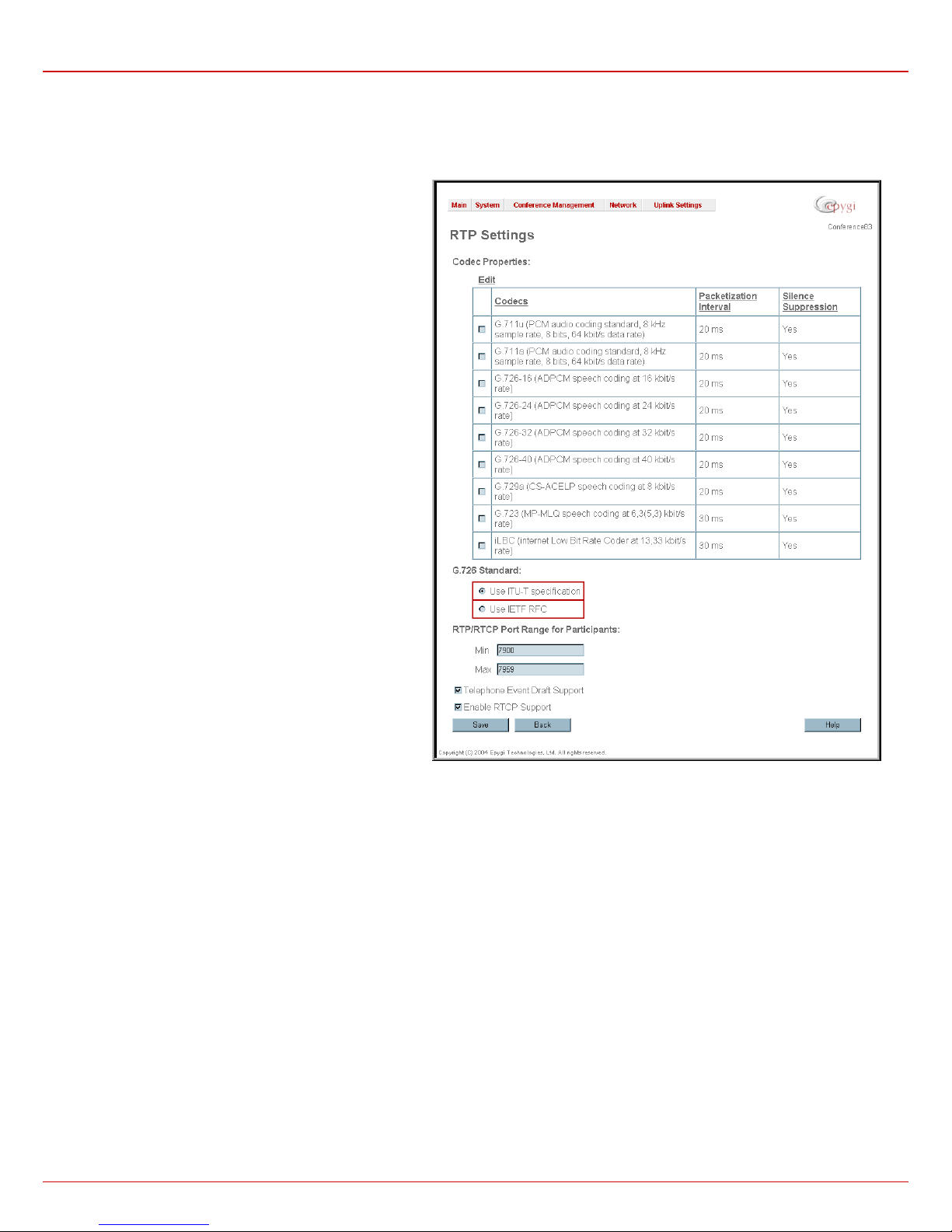
The RTP Settings page allows t he administrator to configure the codec’s packet size and silence suppression for each voice codec, to select the
G726 codec standard, to define RTP/RTCP port range and to enable the R TCP support. All parameters listed on this page may be modified and
submitted.
The Codec Properties table lists all codecs with the
corresponding packetization interval and information about
silence suppression.
Edit opens the Edit RTP Settings page where the codec
settings can be modified. To use Edit, only one codec may be
selected at a time, otherwise an error occurs: “One record
should be selected”.
The Packetization Interval is the time interval between two
RTP packets of the same stream. If the interval is increased,
the overhead is decreased but the voice quality may
deteriorate as a result. If the interval is decreased, the network
load is increased and the delay is reduced.
Silence Suppression disables RTP packet transmission in
case of no voice activity. This feature helps to avoid extra
traffic if the RTP stream contains no voice. It is activated after 2
seconds of silence and restarted immediately if any audio
appears.
The G.726 Standard radio butto ns are used to select the type
of packaging the G.726 code words into octets. If you
experience problems with G.726 voice quality having one of
these packaging types selected, try the other one.
• If Use ITU_T specification is selected, the ITU I.366.2
(“AAL2 type 2 service specific convergence sublayer for
narrow-band services”) type packaging of code words is
used, where packing code words into octets is starting from
the most significant rather than the least significant position
in the octet.
• If Use IETF RFC is selected, the IETF RFC (“RTP Profile for
Audio and Video Conferences with Minimal Control”) type
packaging of code words is used, where packing code words
is starting from the least significant position in the octet.
RTP/RTCP Port Range for Participants:
Min – minimal port has to be higher than 1024 and lower than the maximal port range. Only even numbers are allowed.
Max – maximal port has to be lower than 65536 and higher than the minimal port range. Only odd numbers are allowed.
As the specified maximum port has to be higher than the minimum port, the error message “Min port number should be less than max port number”
will occur if this condition is not met.
allowed” occurs. The difference between Max and Min RTP ports should be 50 ports or less (according to system capabilities) otherwise a
corresponding warning appears. RTP/RTCP Port range cannot include the defined SIP UDP port. Otherwise “Mapped port fo r SIP shouldn't be in
RTP port range” error appears.
Telephone Event Draft Support enables telephony events transmission according to the draft-ietf-avt-rfc2833bis-04. The checkbox needs to be
toggled if the SIP destination party phone or IVR has problems recognizing DTMFs generated by the Quadro.
Enable RTCP Support checkbox enables Real Time Control Protocol support and allows the transmission of RTCP packets. RTCP protocol is used
for monitoring the RTP streams and changing RTP characteristics depending on the Network conditions.
The port range may consist of digits only, otherwise the error “I ncorrect Port Range: only Integer values
Fig. II-38: RTP Settings page
QuadroCS (SW Version 3.0.x) 26
Page 27
QuadroCS Manual II: Administrator's Guide Administrator's Menus
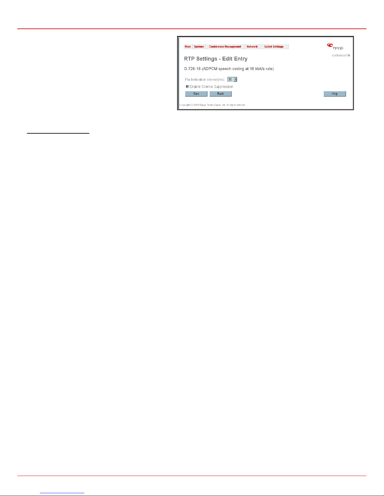
The RTP Settings – Edit Entry page contains two drop down
lists and a checkbox:
Packetization Interval contains possible values (in
milliseconds) to be configured for the selected codec.
The Enable Silence Suppression checkbox selection enables
voice activity detection for the selected codec.
Fig. II-39: RTP Settings – Edit Entry
To Edit Codec Parameters
1. Select the codec from the Codecs Table that is to be edited.
2. Press the Edit button on the RTP Settings page. The Edit Entry page will appear in the browser window.
3. Change values in Packetization Interval and/or enable/disable Silence Suppression.
4. To save the codec settings press Save or click Back to keep the initial data.
QuadroCS (SW Version 3.0.x) 27
Page 28
QuadroCS Manual II: Administrator's Guide Administrator's Menus
NAT Traversal Settings
NAT Traversal Settings page c onsists of five separate pages to configure SIP NAT parameters, RTP and STUN paramete rs for NAT and a page
where the NAT Exclusion table may be filled.
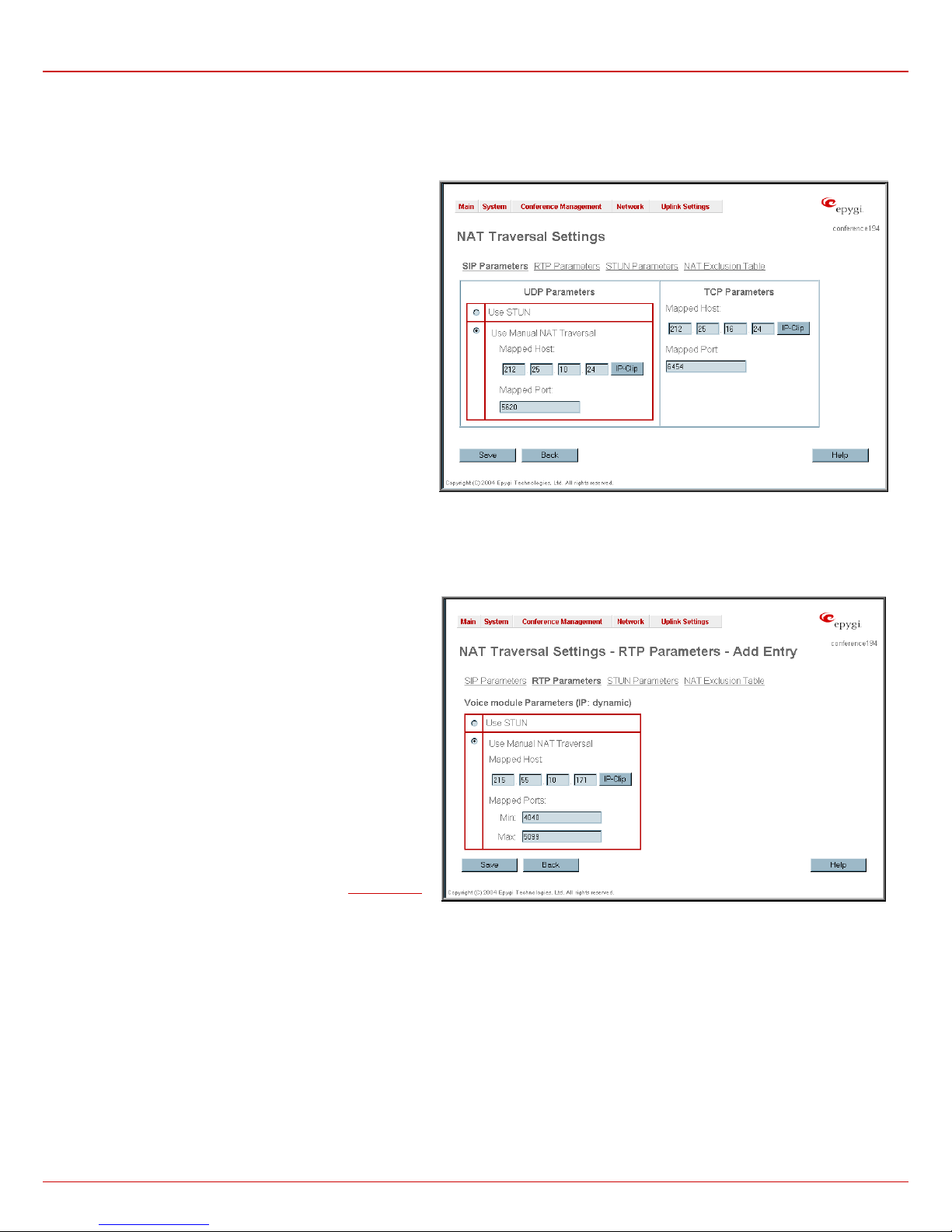
The SIP Parameters page is used to configure NAT specific
settings for SIP. It consists of two independent group of settings:
UDP Parameters:
Manipulation radio buttons allow to select the type of connection
over NAT:
• Selecting Use STUN will switch to automatic discovery of
Mapped settings for the SIP UDP traffic over NAT. STUN
settings are configured in the STUN parameters page (see
below).
• Selecting Use Manual NAT Traversal allows to define
manually the mapped settings for the SIP UDP traffic over
NAT:
Mapped Host requires the IP address of the mapped host
for SIP UDP traffic over NAT.
Mapped Port requires the port number on the mapped
host for the SIP UDP traffic over NAT.
TCP Parameters:
Mapped Host requires the IP address of the mapped host
for SIP TCP traffic over NAT.
Mapped Port requires the port number on the mapped
host for the SIP TCP traffic over NAT.
The RTP Parameters page is used to choose between the
STUN and Manual NAT traversal connection for the RTP traffic
and to define the RTP/RTCP ports for the connection over NAT
for each voice module.
Manipulation radio buttons allow to select the type of connection
over NAT:
• Selecting Use STUN will switch to automatic discovery of
Mapped settings for the RTP UDP traffic over NAT. STUN
settings are configured in the STUN Parameters page (see
below).
• Selecting Use Manual NAT Traversal allows to manually
define the RTP/RTCP port ranges for the RTP traffic over
NAT:
Mapped Host requires the IP address of the mapped
host for RTP traffic over NAT.
Mapped Ports:
Min – minimal port number has to be higher than
1024 and lower than the maximal port range. Only
even numbers are allowed.
Max – maximal port number has to be lower than
65536 and higher than the minimal port range. Only
odd numbers are allowed.
Please Note: RTP/RTCP Mapped Port range should be more or
equal to the RTP/RTCP port range defined on the
page.
RTP Settings
Fig.0-40 SIP Parameters page
Fig.0-41 RTP Parameters page
QuadroCS (SW Version 3.0.x) 28
Page 29
QuadroCS Manual II: Administrator's Guide Administrator's Menus
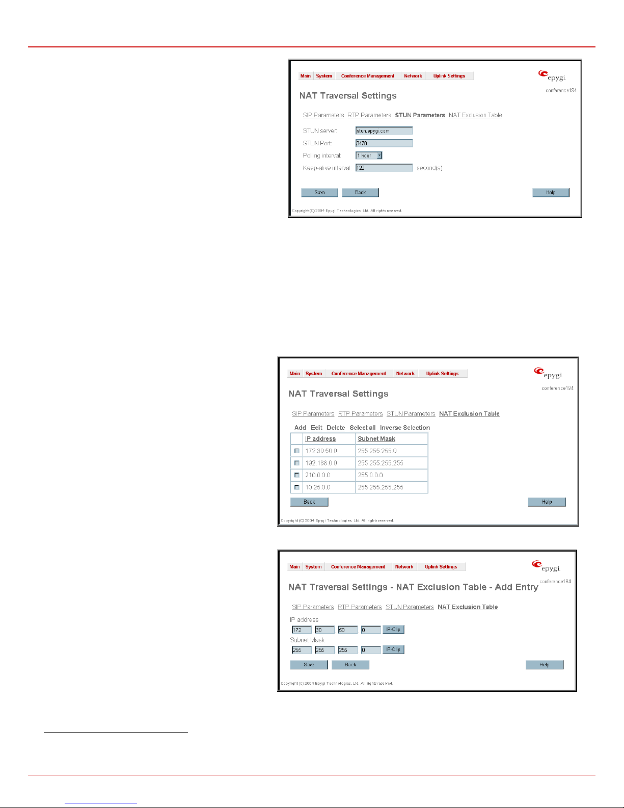
The STUN Parameters page enables automatic NAT
configuration through the STUN server and is used to configure
the STUN (Simple Traversal of UDP over NAT) client on the
Quadro. The page requires following data to be inserted:
The STUN Server text field requires the STUN server’s
hostname or IP address. The STUN Port text fiel d requires the
STUN server port number.
The Polling Interval drop down list contains the possible time
intervals between referrals to the STUN server.
The Keep-alive interval text field gives the possibility to select
the time interval (in seconds) for keeping NAT mapping alive.
Fig.0-42 STUN Parameters page
The NAT Exclusion Table pag e includes a table where all possible LAN IP ranges are listed that allows to exclude some network addresses from
being NATed. For example, if you have several Quadros with a SIP proxy server within the same local network, then NAT (Network Address
Translation) should not be used for those devices. If this type of network configuration exists, and NAT traversal must be used, then this table must
be filled in first before enabling NAT traversal. Otherwise, a malfunction may occur in SIP operations.
The NAT Exclusion Table page offers the following input options:
Each record in the table has its checkbox assigned to its row. It is used to delete or to edit the corresponding record. An error occurs if no records
are selected and the user activates the delete or edit button: “No records selected." The error message "One record should be selected” is
displayed, if the user tries to edit more than one record at the same time. Each column heading in the table is created as a link. By clicking on the
column heading, the table will be sorted by the selected column. Upon sorting (ascending, descending), arrows will be displayed close to the colum n
heading.
The Add Entry page includes the following text fields:
Add opens the Add Entry page where new LAN IP range
can be added.
Edit opens the Edit Entry page where the LAN IP range can
be modified. The page includes the same components as the
Add Entry page.
The NAT Exclusion Table lists all possible LAN IP ranges
that are not included into the NAT process, but may be
accessed directly. IP addresses that are not listed in the NAT
Exclusion Table are accessed over NAT.
IP address requires the IP address that is placed behind
NAT within the LAN network.
Subnet Mask requires the subnet Mask corresponding to the
specified IP address.
Fig.0-44 NAT Exclusion Table - Add Entry page
Configuring the NAT Exclusion Table
1. Press the Add button on the NAT Exclusion Table page. The Add Entry page will appear in the browser window.
2. Specify an IP Address and its Subnet Mask in the corresponding text fields.
3. Press Save on the Add Entry page to add the selected IP range to the NAT Exclusion Table list.
Fig.0-43 NAT Exclusion Table page
QuadroCS (SW Version 3.0.x) 29
Page 30

QuadroCS Manual II: Administrator's Guide Administrator's Menus
To Delete an IP Range from the NAT Exclusion Table
1. Select the checkboxes of the corresponding IP range(s) that ought to be deleted from the NAT Exclusion Table. Press Select all if all IP
ranges ought to be deleted.
2. Press the Delete button on the NAT Exclusion Table page.
3. Confirm the deletion with Yes. The IP range will be deleted. To abort the deletion and keep the IP range in the list, press No.
QuadroCS (SW Version 3.0.x) 30
Page 31
QuadroCS Manual II: Administrator's Guide Administrator's Menus
Statistics
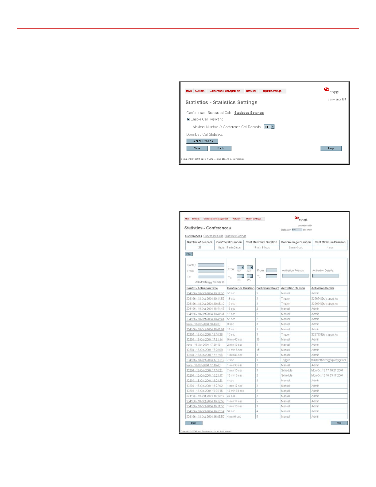
The Statistics page consists of three pages with conference statistics on the first page, successful call statistics on the second page and the
statistics settings on the third page. Statistics allows collecting conference call events on the QuadroCS with their parameters and to search them b y
various criteria.
The Statistics Settings page contains the following components:
The Enable Call Reporting checkbox enables conference calls
statistics reporting.
The Maximal Number of Conference Call Records drop down
list is used to select the maximum number of statistics records to
be collected and shown in the Statistics table.
If the record number exceeds the numbers specified in this drop
down list, the oldest record will be deleted automatically.
The Download Call Statistics link is used to download all
statistics in a file that can be viewed with the simple text editor.
Please Note: If you consider the statistics entries in the displayed
tables to be important, it is recommended to download the
statistics prior to Firmware Update which will clear all statistics on
the QuadroCS.
The Clear all Records button is used to clear all displayed
statistics.
Fig. II-45: Call Statistics Settings page
The Conferences page displays a table with detailed information
(Activation Time, Conference Duration, Participants Count,
Activation Reason and Activation Details) about the established
conferences and gives the possibility to view the component calls
of a particular conference.
To do so, click on the corresponding conference ID. To view all
calls directed to or dialed out of the QuadroCS, move to the
Successful Calls page where the call details table (Activation
Time, Conference Duration, Participant, Call Start Time and Call
Duration) is displayed.
Each column heading in the aforementioned
tables is made as a
link. By clicking on the column heading, the tables will be sorted by
the selected column. Upon sorting (ascending or descending),
arrows will be displayed close to the column heading.
For both Conferences and Successful Calls pages, the statistics
summary and the search components are present.
The statistics summary contains the Number or (Call) Records
that displays the total number of conference entries or successful
calls in the corresponding tables. Additionally Conf Total
Duration, Conf Maximum Duration, Conf Average Duration and
Conf Minimum Duration columns provide information about the
total, maximum, average and minimum durations of the
conferences.
Search components allow to filter the Conferences or Successful
Calls tables:
The ConfID text field requires the ID of the conference call. Only
numeric values are allowed for this field.
The From and To text fields above the Activation Time column
are used to search conferences by its activation date and time.
This data must be entered in the following format: dd-mm-yyyy
hh:mm:ss. However, the time criteria are optional. From requires
an earlier date and time than the To date and time. If the entered
data does not meet this condition, the error message “Minimal
date should be less than maximal date” is displayed and statistics
filtering is aborted.
The From and To drop down lists above the Conference
Duration column are used to search by conference duration. The
duration has to be selected from the listed values. The From field
has to indicate a smaller value than the To field. If the inserted
data does not meet this condition, the error message “Minimal
duration should be less than maximal duration” prevents statistics
filtering.
Fig. II-46: Call Statistics page
The From and To text fields above the Participant Count column are used to search by the number of participants in the conference. You can
perform manual, trigger or scheduled searches of conferences by using the Activation Reason text field.
QuadroCS (SW Version 3.0.x) 31
Page 32

QuadroCS Manual II: Administrator's Guide Administrator's Menus
Conferences can be searched by their activation details by using the Activation Details text field. The following options are available:
For Manual, the Admin or Moderator; for Trigger, the callers' address; and for Schedule, date and time.
Call participants can be searched by their SIP addresses (see chapter Entering a SIP Addresses correctly) by using the Participant text field located
in the Successful Calls table. If the defined SIP address is inserted incorrectly, the error “Participant address is incorrect” will prevent filtering.
The From and To text fields above the Call Start Time column in the Successful Calls table are used to search incoming or outgoing calls by the
call start date and time. The data has to be entered in the following format: dd-mm-yyyy hh:mm:ss. The time criteria are optional. From requires an
earlier date and time than the To field. If the entered data does not meet this condition, the error message “Minimal date should be less than
maximal date” prevents statistics filtering.
The From and To drop down lists above the Call Duration column in the Successful Calls table are used to search by the call duration. The
duration has to be selected from the listed values. The From field has to indicate a shorter duration than the To field. If the inserted data does not
meet this condition, the error message “Minimal duration should be less than maximal duration” prevents statistics filtering.
Filter performs a search procedure by the selected criteria. The search may be done with several criteria at once.
To Enable/Disable the Statistics
1. Enter the Statistics Settings page.
2. Select/deselect the Enable Call Reporting checkbox to enable/disable conference statistics recording.
3. If enabling the statistics, the maximum number of records to be stored in the statistics table should be selected from the corresponding drop
down list.
4. Press Save to apply the new configuration.
To Filter the Statistics
1. Enter the desired criteria fields.
2. Press the Filter button to search the call reports within the Statistics table.
Please Note: To return to the complete Statistics Table clear all search criteria and press Filter.
To Reset the Statistics
1. Press the Clear All Records button in the Statistics Settings page.
2. Confirm the deletion by clicking Yes. The conference statistics will be deleted. To abort the deletion and keep the statistics information, click
No.
QuadroCS (SW Version 3.0.x) 32
Page 33
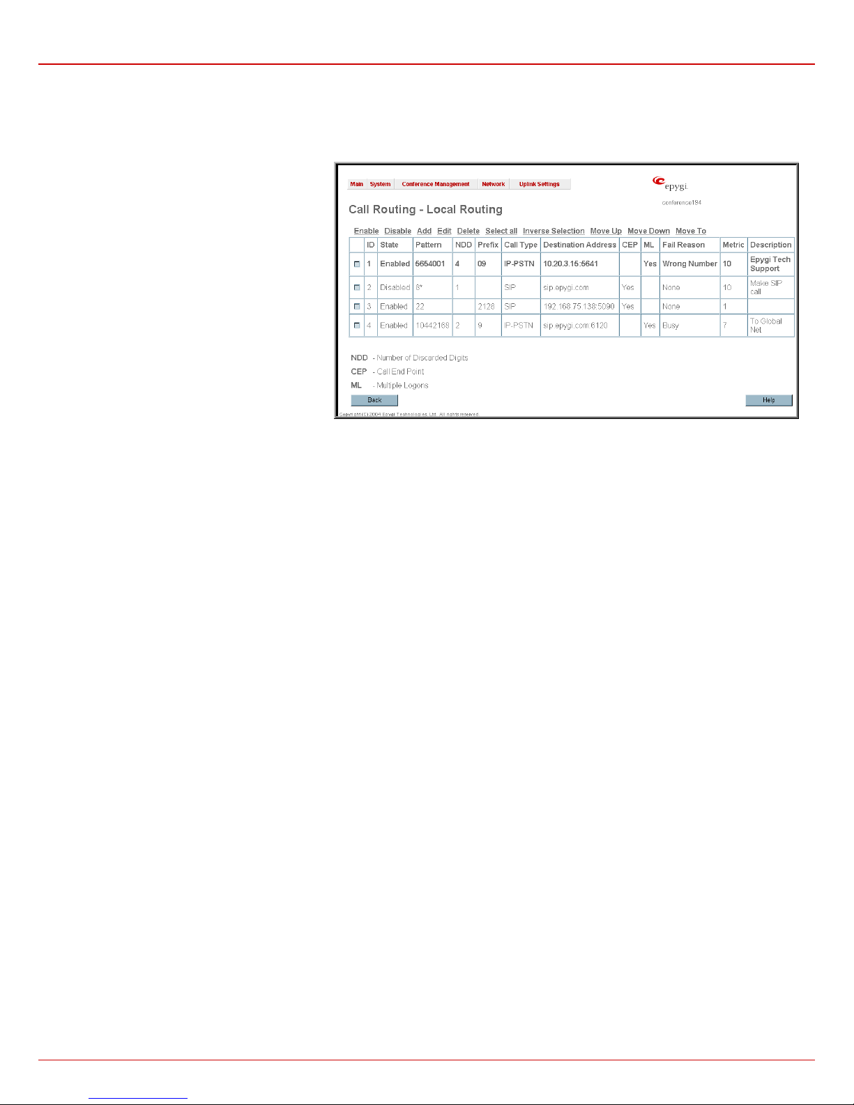
QuadroCS Manual II: Administrator's Guide Administrator's Menus
Call Routing Table
The Call Routing service simplifies the calling procedure for Quadro users, i.e., SIP or IP-PSTN can be accomplished in the same way. With Local
Routing, each Quadro uses its routing resources set by the Qua dro administrator in the Local Routing Table. No SIP registration is needed to
make routing calls.
Defining patterns in the Local Routing Table
avoids registering Quadro at the routing
management server and gives a possibility to
establish a direct connection to the destination or to
use a SIP server for call routing.
The Local Routing Table lists manually created
routing patterns with their parameters (pattern
number, state, routing settings, metric and
description).
Since Local Routing Table may have multiple entries that could match to same pattern, the table will be internally rearranged according to the rules
with these consequences:
• The pattern matching best to the Best Matching algorithm will have the higher position in the rearranged list
• If multiple patterns equally match to the Best Matching algorithm, the pattern with the lower metric will get the higher position in the rearranged
list
• If the multiple patterns with the same metric have been matched to the Best Matching algorithm, the pattern in the higher position in the table
will get the higher position in the rearranged list.
The pattern in the highest position of the rearranged list will be considered as the preferred one. Second and subsequent matching patterns will be
used, if the destination refused the call due to the configured Fail Reason.
The Enable/Disable functional buttons are used to enable/disable the selected ro ute(s). Disabled ro utes will take no effect while enabled routes will
be parsed when initiating routing calls. The State column in the Local Routing Table displays the current state of the routes (enabled/disabled).
Add starts the Local Call Routing Wizard where a new routing pattern may be defined. The Local Call Routing Wizard is divided into severa l
pages: Page 1 displays the following components:
The Pattern text field requires entering the routing pattern identification. To make a specified call, the appropriate routing pattern should be dialed.
Error message prevents saving a routing pattern, when pattern starts with the 0. Wildcard symbols are allowed here. '[' , ']' , ',', '-', ‘{‘, ‘ }’ are used to
define a range or a quantity of numbers, ‘!’ symbol is used for exclusion (“!5a” inserted in Pattern field means all patterns except those equal to 5a).
For example, 2{13-17, ww, a-c} means that the dialed number may be 213, 214, 215, 216, or 217, 2ww, 2a, 2b and 2c to match the specified
pattern; in the case of 2[3,7], the dialed number may be 23 or 27 to match the specified pattern.
Fig. 0-47 Local Routing Table
QuadroCS (SW Version 3.0.x) 33
Page 34
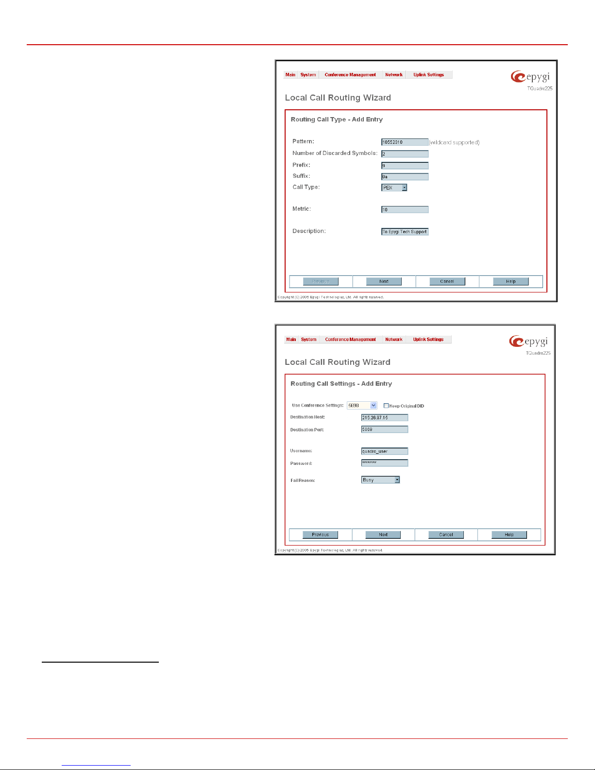
QuadroCS Manual II: Administrator's Guide Administrator's Menus
Number of Discarded Symbols (NDS) requires the number of
symbols that should be discarded from the beginning of the
routing pattern. The field should be empty if no digits need to be
discarded. Only numeric values are allowed for this field,
otherwise an error message occurs: “Error: Number of
Discarded Symbols is incorrect - digits allowed only”.
Prefix requires entering the symbols (letters, digits and any
characters supported in the SIP username) that will be placed in
front of the routing pattern instead of the discarded digits.
Suffix requires entering the symbols (letters, digits and any
characters supported in the SIP username) that will be placed in
the end of the routing pattern. (For example, if the routing
Pattern is 12345, the Number of Discarded Symbols is two,
and the Prefix is 909 and Suffix is 0a, the final phone number
will be 9093450a.)
Call Type gives a possibility to select the call type (SIP or IPPSTN).
Metric allows entering a rating for the selected route in a range
from 0 to 20. If no value is inserted to this field, 10 will be taken
as the default. If two route entries match a user’s dial string, the
route with the lower metric will be chosen.
The Description text field requires an optional description of the
routing pattern.
Fig. 0-48 Local Routing Wizard – Page 1
The second page of the Local Routing Wizard contains
different components depending on the Call Type selected on
the previous page.
Use Conference Settings allows to select the conference on
behalf of the call that will be placed. The SIP settings of the
selected conference will be used as the caller information. If no
entry is selected in this list, the original caller information will be
kept. When Keep original DID checkbox is selected, called
destination will receive the original caller’s information, rather
than the information of conference selected from the Use
Conference Settings list.
The Destination IP Address text field requires the IP address
of the destination (for a direct call) or the SIP server (for calls
through the SIP server).
The Destination Port text field requires the port number of
either the destination or the SIP server.
The User Name and Password text fields require the
identification settings for the public SIP server or servers
requiring authentication.
The Call End Point (CEP) checkbox defines whether the
destination is the end point (the specified user phone will ring) or
a remote destination routing table that should be parsed for
matching patterns to continue the call routing.
The Multiple Logons (ML) checkbox is available for IP-PSTN
call type only and allows or denies multiple logon to the public
SIP server with the same username at the same time.
Fig. 0-49 Local Routing Wizard – Page 2
Fail Reason offers a list of failure reasons (cannot establish connection, wrong number, busy, none and any). If the destination you wish to call is
unavailable, busy, or the dialed number was incorrect (depending on the selected Failure Reason), the local routing table will be parsed for the next.
The Move Up/Move Down buttons are used to move the local routing patterns one level up or down within the Local Routing table. The sequence
of the routing patterns is important as the Local Routing table is parsed from the top down and routing will take place according to the first pattern
that matches the dialed number. The Move To button is used to move the selected entry to a different position in the Local Routing Table, which will
increase or decrease the selected pattern’s priority. Pressing this button will open a page to specify the row number and the desired position of the
selected entry (before or after the defined row).
To create Local Routing pattern
1. Click on the Local Routing Table link on the Call Routing page.
2. Press the Add button on the Local Routing page.
3. Select the Call Type from the drop down list.
4. Specify the Pattern in the corresponding field.
5. Select the Number of Discarded Digits and Prefix if required.
6. Enter a Description if needed.
7. Click Next.
QuadroCS (SW Version 3.0.x) 34
Page 35

QuadroCS Manual II: Administrator's Guide Administrator's Menus
8. Specify the Destination IP Address, the Port Number, the Username, the Password and the Call End Point if required. For IP-PSTN calls
enable Multiple Logons if necessary.
9. Choose a Fail Reason from the corresponding drop down list.
10. Press Next.
11. Press Finish to create a local route with the inserted settings.
QuadroCS (SW Version 3.0.x) 35
Page 36
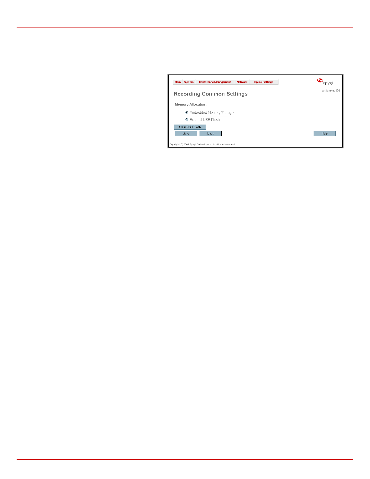
QuadroCS Manual II: Administrator's Guide Administrator's Menus
Recording Common Settings
The Recording Common Settings page is used to configure the memory allocations for recorded conferences. QuadroCS allows USB Flash
Memory for conference voice data file storage. USB Flash Memory is basically a portable hard drive. Using flash memory, the USB Flash Disk is
compact, lightweight, durable and easy to use. USB Flash Disk can be plugged into the available USB port on the QuadroCS.
The Memory Allocation manipulation radio buttons give you a
choice between embedded memory or external USB storage.
• Selecting Embedded Memory Storage will save recorded
conferences internally.
• Selecting External USB Flash Memory allows to save
recorded conferences on the external USB device
attached to the QuadroCS. This will save the space on the
QuadroCS. Selecting the External USB Flash and saving
the page settings will start the USB Flash Memory
automatic configuration.
Fig. II-50: Voice Mail Coming Settings page
The USB Flash Memorymust be formatted to be available on the QuadroCS. Confirmation message will ask for the USB Flash Memory formatting
verification.
Attention: Formatting will erase all data on your USB Flash Disk.
Once the USB Flash Memory has beed formatted, it can be used by QuadroCS again and again. Every time plugging the USB Flash Memory to the
QuadroCS, it will be automatically available. For safely remove the USB Flash Memory will be automatically unmounted first. Error messages appear
either when formatting, mounting and unmounting procedures were unsuccessful and when USB Flash Memory is either write protected or
undetected.
Attention: It is highly recommended to select the Embedded Memory Storage prior to unplugging the USB Flash Memory. Otherwise data stored on
the USB Flash Memory may be corrupted or lost. It is recommended to wait at lease ten seconds
after removing USB Flash before inserting a
different one, otherwise the system may not detect the new device.
When attaching the USB Flash Memory to the QuadroCS, its voice data (if any) will automatically be moved from the QuadroCS’s flash to the USB
Flash Memory. If the USB Flash Memory is too small to fit the recorded conferences on the QuadroCS, the administrator is allowed to choose
between removing the recorded conferences from the QuadroCS’s Flash and switching to the External USB Flash mode or to leave the recorded
conferences on the QuadroCS and continue using the Embedded Memory Storage mode.
Please Note: As QuadroCS allows the use of both its local flash space and the External USB Flash Memor y, recorde d conferences ca n be stored in
both locations depending on the selected Memory Allocation mode. So if a user complains about the loss of a specific conference that was to be
recorded, please verify the memory allocation mode the QuadroCS was in at the time the conference was to have been recorded.
The Clear USB Flash button appears only when the USB Flash Memory Stick is attached to the Quadro and is used for erasing the USB Flashes'
Memory.
Below is the list of USB Flash Memory devices tested and functional with the QuadroCS.
1. San Disk Cruzer mini 256MB
2. JMTek 128MB
3. JMTek USBDrive 32MB
4. Apacer 64MB
5. Pen Drive 64MB
6. Seitec 256MB
7. Lexar JumpDrive 128MB
8. Orange 128MB
9. QuickDrive 128MB
10. Kingston 128MB
11. LinkSys Instant USB Disk 128MB
12. DiskGo Edge Digital Media 128MB
Attention: It is strongly recommended to use one USB Flash Memory. Two sticks cannot be used simultaneously.
QuadroCS (SW Version 3.0.x) 36
Page 37
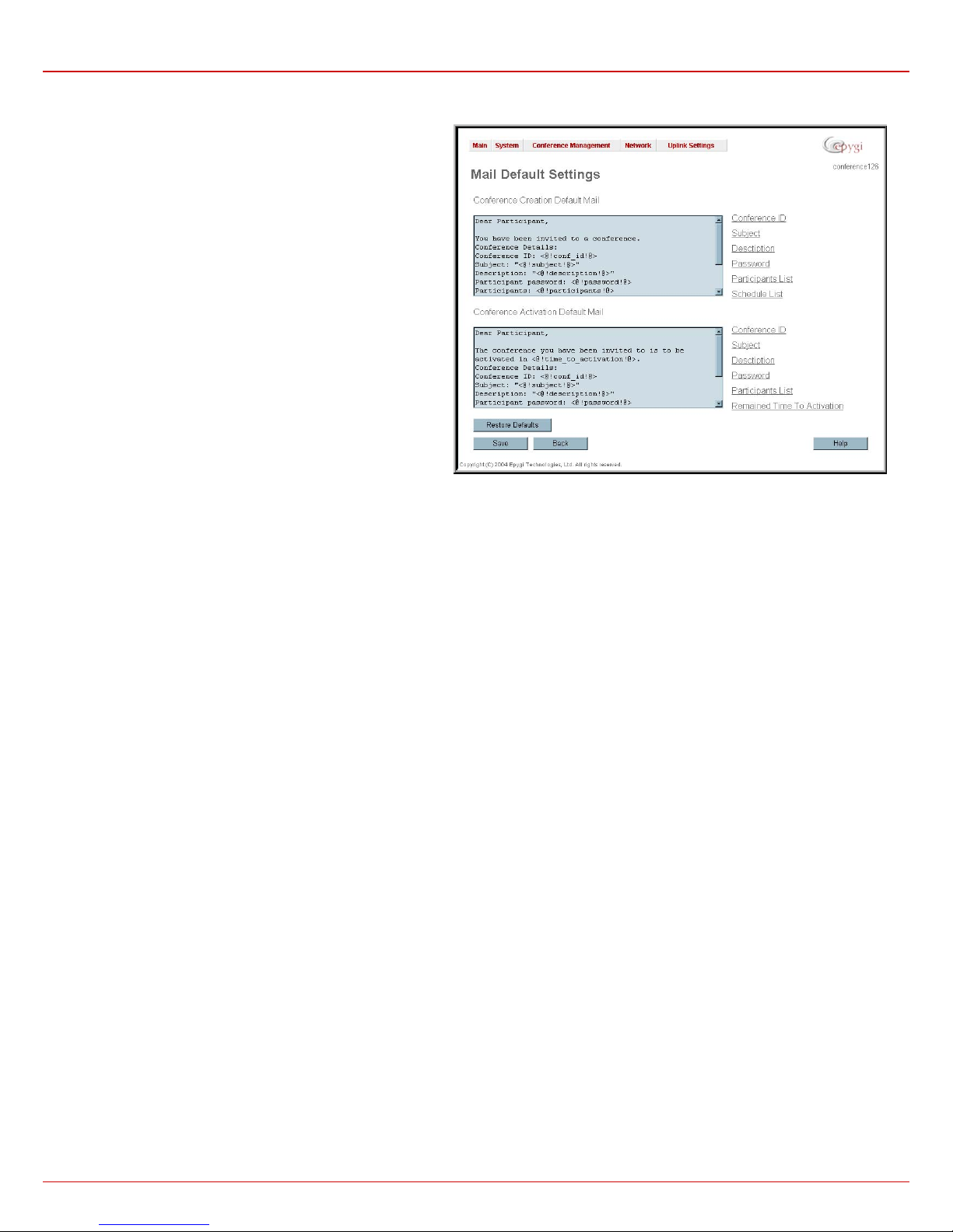
QuadroCS Manual II: Administrator's Guide Administrator's Menus
Mail Default Settings
Mail Default Settings page is used to define the email templates
used in the automatically generated emails from the Quadro
Conference Server to the conference participants. Two email
templates can be defined on this page: for the conference
invitation email and for the conference activation email.
Each template should be defined in the corresponding text field.
Additionally, functional tokens can be used to automatically insert
the Conference ID, Subject, Description, Participants, Password,
Scheduling information, as well as a possibility to display the time
remained until the conference will start, etc.
All these tokens can be inserted by using the links on the right side
of the page.
Please Note: Changing the body of the token will disable the token
function and will be implied as a simple text.
The Restore Defaults button is used to restore the defualt mail
templates. Using this button, all user defined mail templates will be
lost.
Fig. II-51: Email Default Settings page
QuadroCS (SW Version 3.0.x) 37
Page 38
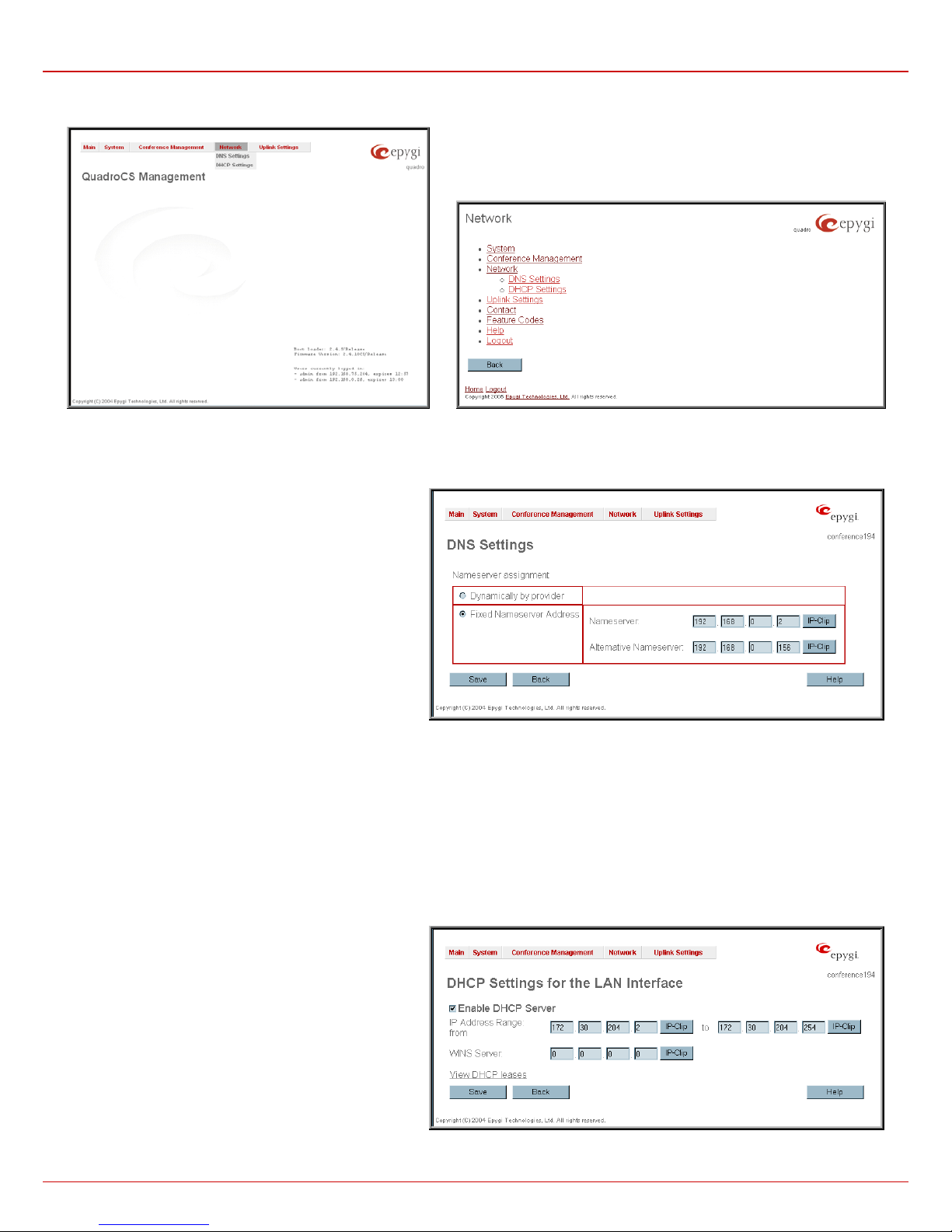
QuadroCS Manual II: Administrator's Guide Administrator's Menus
Network Menu
Fig. II-52 Network Dynamo Menu
DNS Settings
The DNS Settings page gives the possibility to setup a name
server for the QuadroCS. It consists of the following
components:
NameserverAssignment radio buttons:
• Dynamically by provider automatically configures the
assignment of the name server address from the provider
party.
• Fixed Nameserver address - manually selected name
server. The Nameserver text field requires the IP address
of an external name server. The Alternative Nameserver
text field requires the IP address of the secondary name
server. The Alternative Nameserver is used if the main
name server cannot be accessed.
DHCP Settings
The DHCP Settings page gives the possibility to enable a
DHCP server and control the QuadroCS user’s LAN settings.
Thus QuadroCS LAN users will be provided automatically with
the following settings using the configured parameters:
• IP addresses
• NTP (corresponds to the QuadroCS’s IP address)
• WINS server
• Nameserver (corresponds to the QuadroCS’s IP address)
• Domain name
The page DHCP Settings offers the following input options:
Enable DHCP Server activates the DHCP server on
QuadroCS.
IP Address Range defines a range of IP addresses that will
be assigned to the QuadroCS’s LAN users. The IP range must
be at least 6, otherwise the “Address Range too small” error
will prevent saving. The “Address Range too large” error
occurs if the IP range is greater than 254.
WINS Server defines a WINS server IP address for the
QuadroCS’s LAN users.
View DHCP Leases leads to the page where the DHCP
leased LAN IP addresses are listed.
Fig. II-55: DHCP Settings page for LAN interface
Fig. II-53: Network Tree Menu
Fig. II-54: DNS Settings page
QuadroCS (SW Version 3.0.x) 38
Page 39
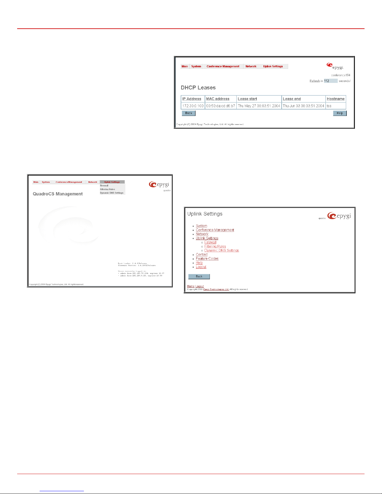
QuadroCS Manual II: Administrator's Guide Administrator's Menus
The DHCP Leased IP Addresses page includes a list of the
leased host addresses that are part of the QuadroCS’s LAN.
For these hosts QuadroCS acts as a server supplying them
with a unique IP address. It consists of a non-editable table
describing all the leased IP hosts and their parameters. The
table contains the following columns:
IP address - host IP address, assigned by QuadroCS.
MAC address - host MAC address, provided by the host itself.
Lease Start - date and time when the leased IP address has
been activated.
Lease End - date and time when the leased IP address has
been deactivated.
Hostname - hostname, provided by the host itself.
Fig. II-56: DHCP Leases page for LAN interface
Uplink Settings Menu
Fig. II-57 Uplink Settings Dynamo Menu
Fig. II-58: Uplink Settings Tree Menu
QuadroCS (SW Version 3.0.x) 39
Page 40
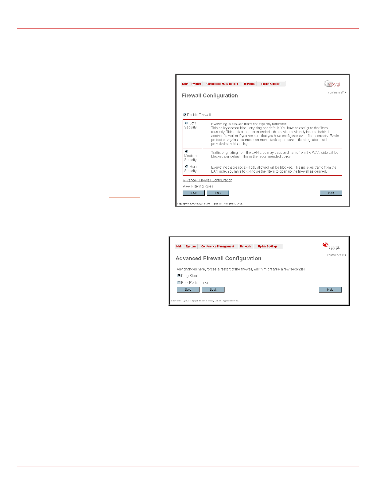
QuadroCS Manual II: Administrator's Guide Administrator's Menus
Firewall
The Firewall Configuration page allows setting up a firewall, configuring the security level of QuadroCS.
A Firewall is a security service configured by the QuadroCS administrator based on various criteria. The firewall allows or blocks traffic based on
policies, services and/or IP addresses. The firewall has several levels of security policies (low, medium, high). The administrator may add additional
service-based rules. Filtering rules will take effect only if the Firewall has been enabled and are independent from the selected firewall security level.
The Firewall Configuration page consists of the following
components:
The Enable Firewall checkbox selection enables the firewall
security service. The firewall security level has to be selected,
otherwise the firewall cannot be enabled.
The Firewall Security radio buttons are:
• Low Security - Everything that is not explicitly forbidden is
allowed. This security level doesn't block anything by
default. It is recommended if the device is already located
behind another firewall or if every filter has been configured
correctly.
• Medium Security - Traffic originating from the LAN side
may pass and traffic from the WAN side will be blocked by
default. This is the recommended security level.
• High Security - Everything that is not explicitly allowed will
be blocked, including traffic from the LAN side.
Advanced Firewall Settings link refers to page where QuadroCS
privacy can be configured.
The View Filter Rules link opens the Filtering Rules
page.
Advanced Firewall Settings
Advanced Firewall Settings are used to deny Ping and
Portscanning operations addressed toward the device. With
these features enabled QuadroCS will answer with irritating
message to the Ping and Portscanning operations. Page
consists of the following components:
The Ping Stealth checkbox selection prohibits Ping operation
toward QuadroCS from its WAN.
The Fool Portscanner checkbox selection prohibits
QuadroCS portscanning from its WAN. As a reply to
Portscanning operation, "network unreachable" or "host
unreachable" feedback messages will be sent.
Fig. II-59: Firewall and NAT Settings page
Fig. II-60: Advanced Firewall Settings page
QuadroCS (SW Version 3.0.x) 40
Page 41
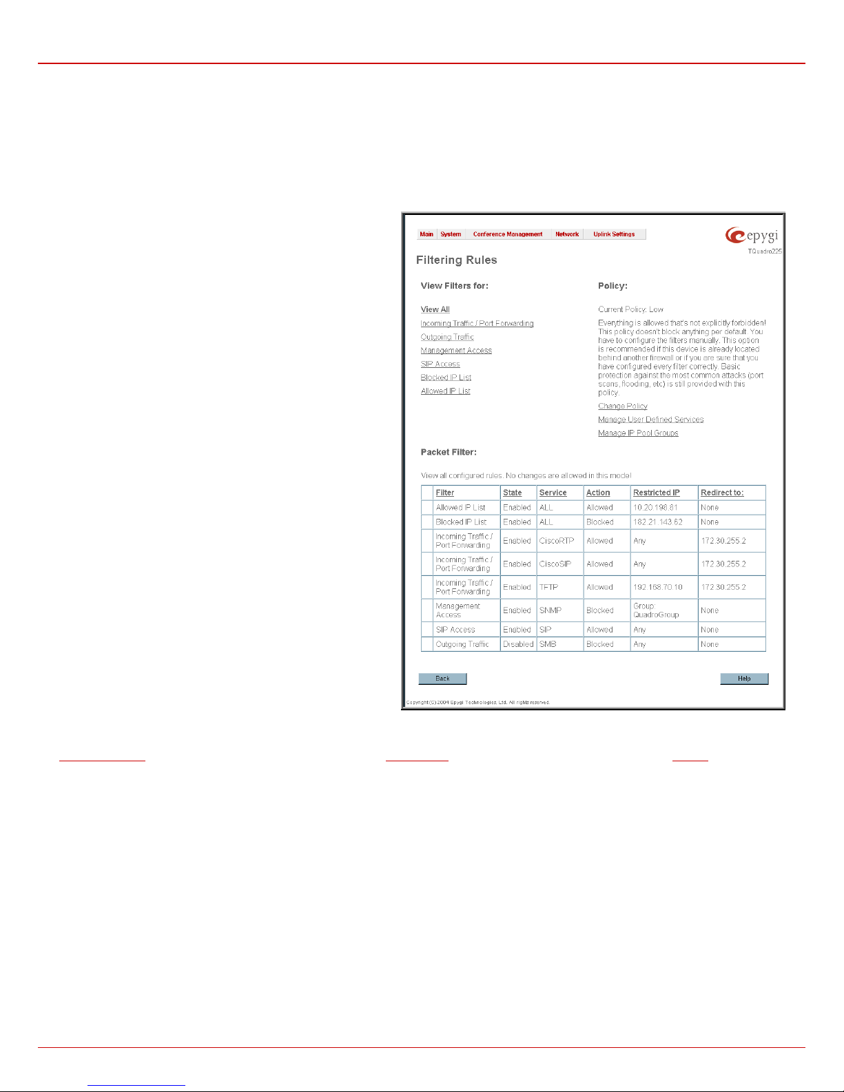
QuadroCS Manual II: Administrator's Guide Administrator's Menus
Filtering Rules
The Filtering Rules page allows the configuration of filters for the incoming and outgoing traffic.
To prevent misconfiguration, only one rule per service is allowed. The user may use IP groups to include several IP addresses for this rule. As the
filtering rules specify the operation mode of the firewall, they only take effect if the firewall has been e nabled (additionall y NAT should be enabled to
use the Port Forwarding function in the Incoming Traffic / Port Forwarding filtering rules). The filtering rules are independent from the security
level, so they will work if enabled, no matter what security level has been selected.
Please Note: Applying firewall rules will just prevent the establishment of new connections that violate the rules. Applying rules does not kill existing
connections that violate the rule.
View All displays all configured filters specified by their State
(enabled or disabled), the selected Service, the set Action
(allowed or blocked), the IP addresses the filters apply to (if
Restricted) and the destination of port forwarding (Redirect to,
in case of Incoming Traffic/Port Forwarding). As it is read-only,
no modifications are allowed and no functional buttons are
available.
The Incoming Traffic/Port Forwarding filter is for incoming
traffic. The rules here allow or deny systems on the Internet to
reach the services of Quadro’s LAN. NAT service should be
enabled on the Quadro to provide the possibility of Port
Forwarding in the Incoming Traffic/Port Forwarding filtering
rules. The Port Forwarding function will be unavailable if NAT is
disabled on the Quadro.
The Outgoing Traffic filter is for outgoing traffic. The rules here
allow or deny Quadro’s LAN users to reach external services.
Management Access is used to enable management access to
the Quadro from the Internet. A host on the Internet can be
allowed to reach the Quadro.
SIP Access is to allow or deny the SIP access to or from the
particular SIP servers, SIP hosts or a group of them. The SIP
Access filtering rule may prevent or allow incoming or outgoing
SIP calls to or from specified SIP server(s) or host(s).
When Blocked IP List is used, traffic from specific hosts may be
blocked, no matter what services are opened in the other filters.
NO traffic will be allowed to the specified hosts. The Blocked IP
List service has a higher priority if the same host is also listed in
the Allowed IP List table.
Allowed IP List allows trusted hosts to reach your network and
vice versa. It is an exception to other rules and only all services
may be allowed for a single host.
The Filtering Rules page provides several links. Each link opens its specific parameters on the same page. Only Change Policy (see chapter
Firewall and NAT
separate pages. The Filtering Rules page also includes the currently selected firewall security (Policy) level and its description.
The table displayed on the bottom of the page shows the filters selected above, specified by their State (enabled or disabled), the selected Service,
the set Action (allowed or blocked), the IP addresses the filters apply to (if Restricted) and the destination of port forwarding (Redirect t o, in case
of Incoming Traffic/Port Forwarding). With the exception of View All, the table offers the following functional buttons:
), Manage user Defin ed Services (see chapter Service Pool) and Manage IP P ool Groups (see chapter IP Pool) are leading to
Fig. II-61: Filtering Rules page
• Enable is used to enable the rule. If no records are selected the “No record(s) selected” error occurs.
• Disable is used to disable the rule. If no records are selected the “No record(s) selected” error occurs.
• Add opens a filter specific page where new rules may be defined by a Service, an Action, a Restriction to certain IP address(es) or IP
groups, and if adding a rule for Incoming Traffic/Port Forwarding, the destination IP address for Forwarding:
QuadroCS (SW Version 3.0.x) 41
Page 42
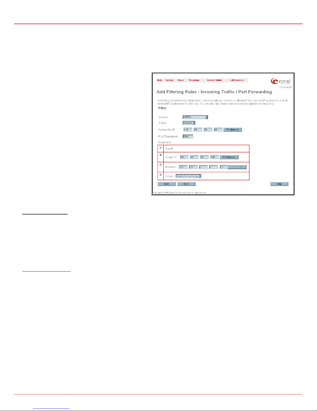
QuadroCS Manual II: Administrator's Guide Administrator's Menus
For example, the page to add a rule for Incoming Traffic/Port
Forwarding offers the following input options:
Service includes a list of possible services to be configured. All
user defined services also will be displayed in this list.
Action includes possible actions to setup the rule.
Forward to IP requires the destination IP address where traffic
should be transferred to, if it comes from the restricted host. The
IP address defined in this field will be ignored for blocked action of
the Incoming Traffic/Port Forwarding rule.
Note: It is not allowed to forward incoming packets when NAT
service is disabled on the Quadro.
Port Translation text field is available for “Allowed” action only
and optionally requires the port number that will stand instead of
original port number when incoming packet is being forwarded. If
this field is left empty, original port number will be used upon
forwarding the packet.
Restriction radio buttons:
• Selecting Any blocks or allows all host IP addresses. This
selection is not present for the Management Access,
Blocked and Allowed IP List rules.
• Selecting Single IP will require the IP address of the allowed
or blocked host.
• Selecting IP/Mask will require the subnet to be allowed or
blocked, specified by an IP address and the Maskbits.
Maskbit examples:
255.0.0.0= /8,
255.255.0.0 = /16,
255.255.255.0 = /24,
255.255.255.255= /32
• Group indicates the user defined groups that include IP
addresses that ought to be allowed or blocked.
To Add a Filtering Rule
1. Select the Filter link (Incoming Traffic/Port Forwarding, Outgoing Traffic, Management Access, SIP Access, Blocked IP List or Allowed IP List)
to add a rule for it. The corresponding Filter table will appear in the same window.
2. Click Add on the Filtering R ules page. A page where a new rule may be added will appear in the browser window. The page will be named
corresponding to the selected filter.
3. Select a service name from the Service list to configure a rule for it. If the list has a default value, leave it as is.
4. Select an action from the Action list that is used in the rule. If the list has a default value, leave it as is.
5. Enter the IP address in the Forward to IP field if an Incoming Traffic Rule is to be added.
6. Choose the restriction type by selecting Any, SingleIP or IP/Mask and enter the required information in the text fields or select a group.
7. To add a rule with these parameters press Save.
To Delete Filtering Rules
1. Select the Filter link to delete a rule from its table. The appropriate Filter table will appear in the same window.
2. Check one or more checkboxes of the corresponding rules that ought to be deleted from the rules table. Press Select all if all rules ought to be
deleted.
3. Press the Delete button on the Filtering Rules page.
4. Confirm the deletion with Yes, or cancel it with No.
Fig. II-62: Filtering Rules - Page to add a rule for Incoming Traffic
QuadroCS (SW Version 3.0.x) 42
Page 43
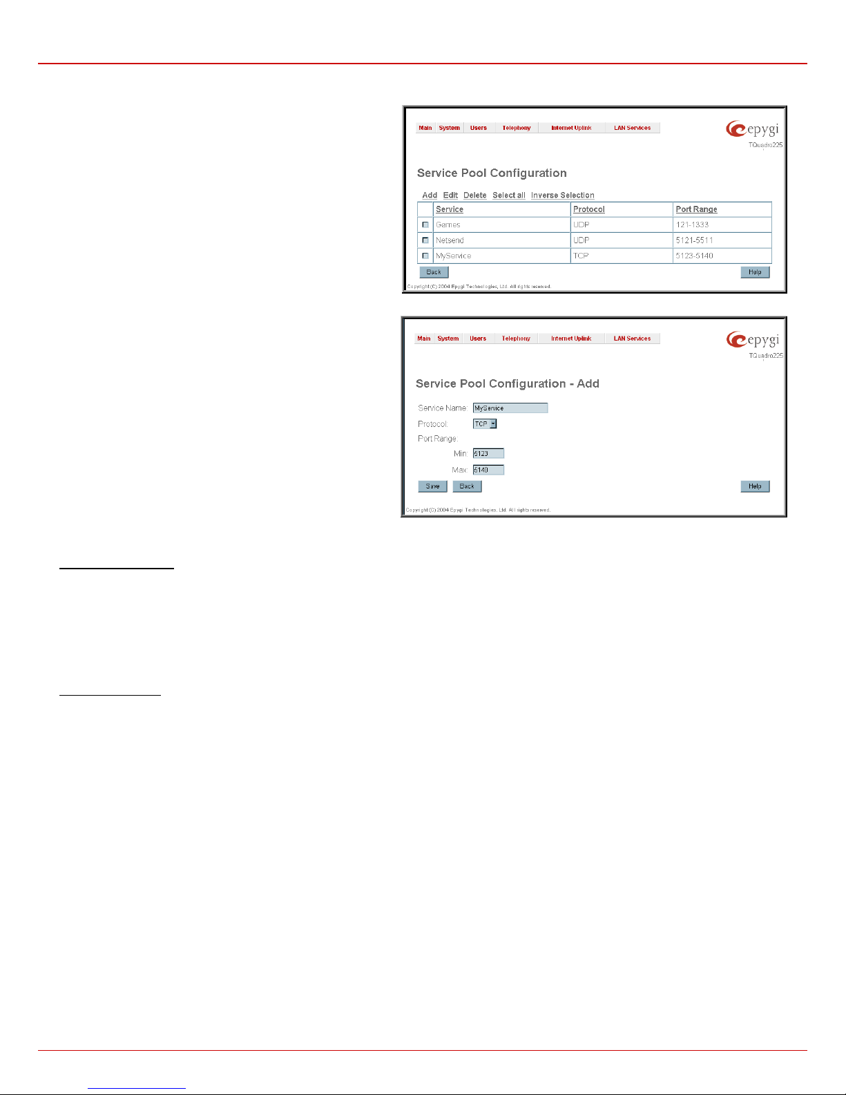
QuadroCS Manual II: Administrator's Guide Administrator's Menus
Service Pool
The Service Pool table is a list of all created services and their
parameters. It is used to add new services with the appropriate
settings (protocol type and port range). New services can be used
to add a restriction or permission by defining a new filtering rule:
Add opens the Add New Service page where new services may
be added.
Edit opens the Edit Service page where the service parameters
(except for the service name) can be modified. This page includes
the same components as the Add N ew S er vi ce page. To operate
with Edit only one record may be selected, otherwise an error will
occur: “One row must be selected”.
Fig. II-63: Service Pool page
The Add page is used to add new services and includes the
following text fields and buttons:
Service Name requires a name for the service that ought to be
added.
Protocol includes a list of possible protocols to be selected.
Port Range requires a port range for the defined service.
Fig. II-64: Service Pool - Page to add a new Service
To Add a new Service
1. Select the Manage User Defined Services link on the Filtering Rules page.
2. Click on the Add button on the Service Pool Configuration page. A page where a new service may be added will appear in the browser
window.
3. Define a service name in the Service Name text field.
4. Select the protocol type for the service from the Protocol drop down list.
5. Enter the port range in the Port Range text fields or leave one of them empty to define a particular port for the service.
6. To add a service with these parameters click on Save.
To Delete a Service
1. Select the Manage User Defined Services link. The Service Pool Configuration page appears with the table of services (if any).
2. Check one or more checkboxes of the corresponding services that ought to be deleted from the Service Pool table. Press Select all if all
services ought to be deleted.
3. Click on the Delete button on the Service Pool Configuration page.
4. Confirm the deletion with Yes, or cancel it with No.
QuadroCS (SW Version 3.0.x) 43
Page 44
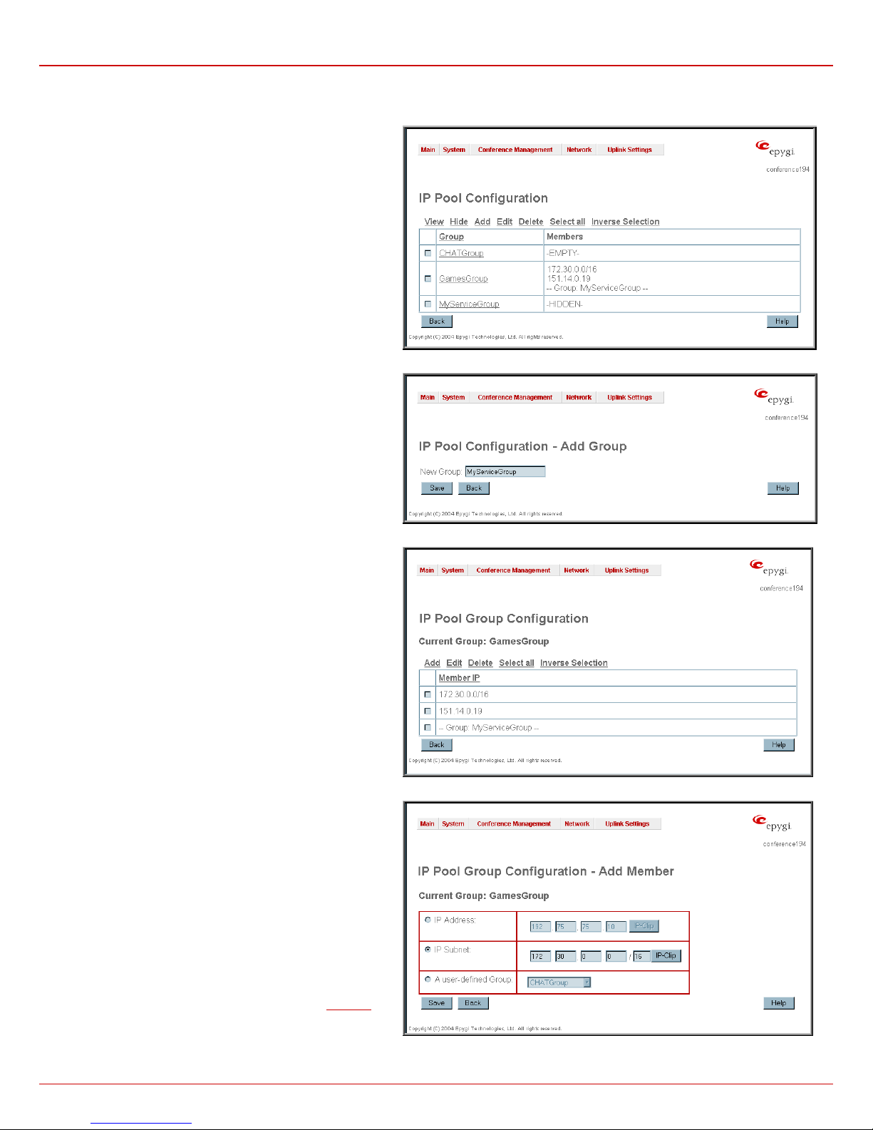
QuadroCS Manual II: Administrator's Guide Administrator's Menus
IP Pool
The Manage IP Pool Groups link opens the IP Pool Configuration page.
The IP Pool table is the list of all created groups and the
members assigned to these groups. If a group is empty, EMPTY
will be indicated in the Members column. If hidden, group
members will still remain active but a HIDDEN will be displayed
in the Members column.
The IP Pool Configuration is used to create groups of IP
addresses, which have the same restriction criteria. Whenever
creating a new filtering rule groups may be used instead of
several IP addresses. It consists of the following components:
View makes hidden groups visible.
Hide makes group members hidden and adds the HIDDEN
comment in the member column.
Add opens the Add Group page where a new group may be
created. This page consists only of the New Group text field
(requiring the group name) and the standard Save and Back
buttons to apply or abort changes.
Edit opens the Edit Group page where the service parameters
can be modified. It consists of the same components as the Add
Group page. To operate with Edit, only one record may be
selected, otherwise an error will occur: “One row must be
selected”.
Please Note: Changing a group name will also change the
references to this group, including groups where this group is a
member of and all affected filter rules (enabled and disabled
ones, in all chains).
Clicking on the Group name will display an IP Pool Group
Configuration page with the Members list for the current
group.
Fig. II-65: IP Pool Configuration page
Fig. II-66: Page to create a new IP Pool group
The IP Pool Group Configuration page displays a list of all
created member IP addresses for the selected group. It consists
of the following components:
Current Group provides read-only information about the current
group name the members are listed for.
Add opens the Add Member page where a new member may
be created.
Edit opens the Edit Members page where the service
parameters can be modified. This page includes the same
components as the Add Me mber page. To operate with Edit,
only one record may be selected, otherwise an error will occur:
“One row must be selected”.
The Add Members page consists of the following radio buttons:
IPaddress requires the member IP address that is to be added
to the group.
IP Subnet requires the subnet specified by the IP address and
the Maskbits. See above for more information about
Maskbits.
The User-defined Group includes previously created groups
that may also be added as a member to another group.
Fig. II-67: IP Pool Group members list
Fig. II-68: Page to add a new member to the IP Pool group
QuadroCS (SW Version 3.0.x) 44
Page 45

QuadroCS Manual II: Administrator's Guide Administrator's Menus
To Create a new Group with Members
1. Select the Manage IP Pool Groups link on the Filtering Rules page.
2. Click on the Add button on the IP Pool Conf igura tion page. A page where a new group may be added will appear in the browser window.
3. Define a group name in the New Group text field.
4. To create a group with given parameters press Save.
5. Open the IP Pool Group Configuration page by clicking on the group name.
6. Select the Add button on the IP Pool Group Configuration page. A page opens where new members may be added to the group.
7. Enter an IP address for the member in the IP Address text fields or select a group from the User defined Group drop down list to assign it to
the currently selected group.
8. To add a member with these parameters to the selected group press Save.
To Delete a Member
1. Select the Manage IP Pool Groups link. The IP Pool Configuration page appears with the table of groups (if any).
2. Click on the desired group the members are needed to be deleted for. The IP Pool Group Configuration list appears.
3. Check the one or more checkboxes of the corresponding members that ought to be deleted from the Members table. Press Select all if all
members ought to be deleted.
4. Press the Delete button on the IP Pool Group Configuration page.
5. Confirm the deletion with Yes or quit with No.
To Delete a Group
1. Select the Manage IP Pool Groups link. The IP Pool Configuration page appears with the table of groups (if any).
2. Check the one or more checkboxes of the corresponding groups that ought to be deleted from the groups table. Press Select all if all groups
ought to be deleted.
3. Press the Delete button on the IP Pool Configuration page
4. Confirm the deletion with Yes or quit with No.
QuadroCS (SW Version 3.0.x) 45
Page 46
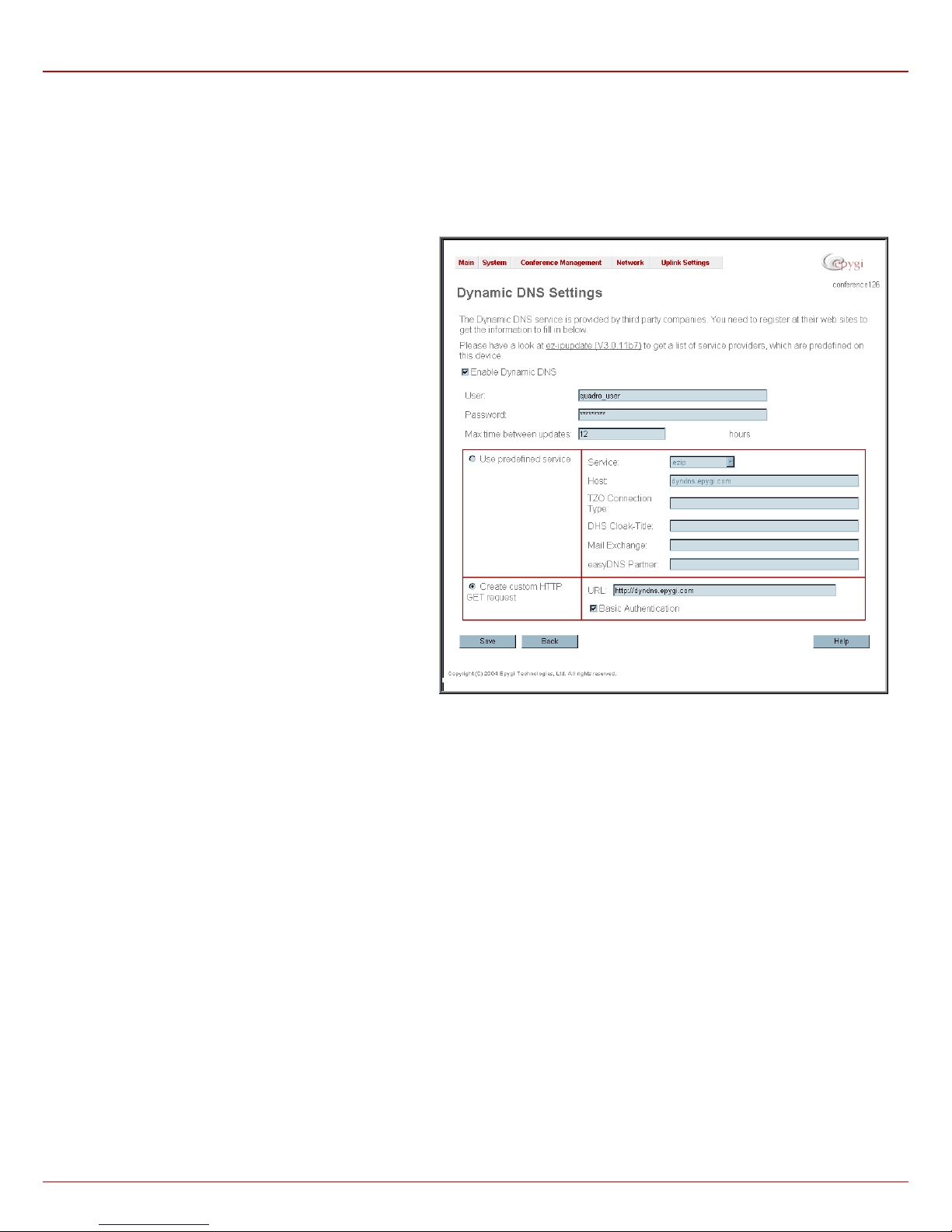
QuadroCS Manual II: Administrator's Guide Administrator's Menus
Dynamic DNS Settings
The Dynamic DNS (DynDNS) is a service that is used to map a dynamic IP address to a host name. Thus this service is only makes sense if you
are connected to the Internet with a dynamic IP address (and DHCP client) and want to allow access from the Internet to a device behind the
firewall. For example, if you want to run your own WEB server.
To enable the DynDNS service on Quadro you first have to choose a DynDNS provider and register at his WEB site.
The Dynamic DNS Settings page consists of the following
components:
The Enable Dynamic DNS checkbox selection enables the
dynamic DNS service.
The User text field requires the username specified during the
registration at the DynDNS provider.
The Password text field requires the pass word specified during
the registration at the DynDNS provider.
The Max time between updates text field requires entering the
period between two updates (in hours). The values entered in
this field should be greater than 24, otherwise an error occurs:
“Update interval times smaller than 24 hour are too small”.
Normally, whenever you set up a connection to the Internet the
DynDNS is updated at least once in the period indicated in this
field.
The Use predefined service radio button leads to the manual
configuration of the DynDNS service. The selection enables the
following optional settings:
The Service drop down list contains the provider list where the
administrator needs to select the one to which he has
subscribed.
The Host text field requires the name of the host in the Internet.
The TZO Connection Type text field is used for a special
parameter required by the DynDNS provider TZO.
The DHS Cloak-Title text field is used for a special parameter
required by the DynDNS provider DHS.
The Mail Exchange text field requires the address of the e-mail
server, to which the DynDNS service provider will relay your emails.
Attention: If this service is used, make sure, that there is port
forwarding configured for SMTP (port 25) to the internal e-mail
server.
The easyDNS Partner text field is used for a special parameter
required by the DynDNS provider easyDNS.
Selected the Create Custom HTTP GET Request radio button switches to the custom settings of the DynDNS service. Normally, the DynDNS
provider uses HTTP get requests to map dynamic IP addresses to host names. If the user knows this HTTP get request exactl y, the radio button
Create Custom HTTP GET Request together with the text field URL allows to enter it directly.
The selection enables the following optional settings:
The URL text field requires the complete request to be sent to the DynDNS server. Normally it has the format:
[http://]www.server.domain:port/scriptpath/scriptname?param1=value1¶m2=value2
The request modifies the nameserver database so that the hostname will be resolved to the new IP address.
The Basic Authentication checkbox enables the encoding of the username and password entered in the text fields above and then uses the Basic
Authentication method to notify the provider about the user authentication settings.
Most of the DynDNS providers require an authentication for safety reasons. The user can do that either together with the HTTP get request in the
text field URL or select the checkbox Basic Authentication.
Fig.0-69 Dynamic DNS Settings page
QuadroCS (SW Version 3.0.x) 46
Page 47
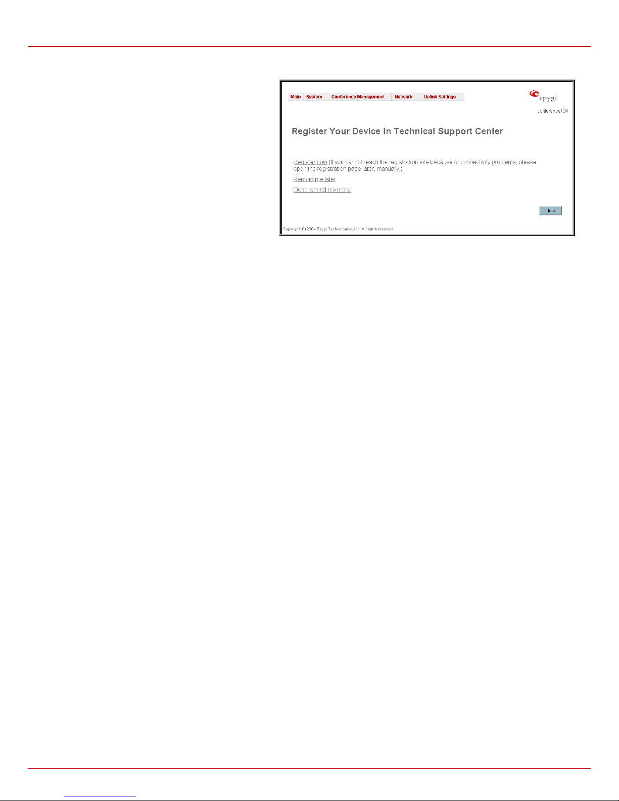
QuadroCS Manual II: Administrator's Guide Administrator's Menus
Registration Form
The Registration Form page appears if unregistered users
login and has been created for customer support purposes.
The page requires customer registration at the Epygi
Technical Support Center. It consists of several links offering
registration options:
Register now leads to the Epygi Technical Support System
Registration page and requires customer’s information to
submit the registration form.
Remind me later hides the registration notification until the
next startup.
Don’t remind me more hides the registration notification
forever.
Fig. II-70: Device Registration page
Logout
This option is used to close the session between the user PC and QuadroCS and to leave the Web Management or to enter the management with
another login. By selecting the button Logout, the startup page will be displayed and the user needs to login again.
QuadroCS (SW Version 3.0.x) 47
Page 48

QuadroCS Manual II: Administrator's Guide Appendix: System Default Values
Appendix: System Default Values
Issue System Default Value Comments
Admin Settings
Quadro Hostname Conference
LAN IP Address 172.30.0.1 Subnet Mask - 255.255.0.0
DHCP Server Enabled
Regional Settings
WAN IP Automatically through DHCP
DNS Server Dynamically
Time/Date Settings
Event Settings
Mail Settings Disabled
Firewall
Filtering Rules SIP Access (Allowed for all). No user-defined IP pool groups.
Login name – admin
Password – 19
Your locale - US,
Time Zone - US/Central,
Theme - Dynamo.
NTP Client – Enabled, NTP server - disabled
Predefined NTP Server - npi1.epygi.com
DynDNS, DHCP client and DHCP server error events are
noted. Display notification for others.
Enabled, Medium level
(NAT is internally enabled by default)
IP Range - 172.30.0.100 -172.30.0.254
WINS - 0.0.0.0
Polling interval - 6 hours
Ping Stealth - enabled
Fool Portscanner - disabled
Dynamic DNS Disabled
Statistics Enabled 100 entries to display
Moderator’s settings for default conference:
Max 10 new participants allowed to join
New participant type - speaker
Confirmation type - none
New participant can activate the conference enabled
New participant indication - enabled
Participants - none
Scheduling - none
Mail notifications - disabled
Codecs - G.711u (preferred), G.711a, G.726/16,
G.726/24, G.726/32, G.726/40, G.729a, G.723,
iLBC
Out of band transport - enabled
Space – 0%
Welcome message - default
ZeroOut - disabled
Properties for all Codecs except G723 and iLBC:
Packetization - 20ms
Silence Suppression - no
G723 and iLBC properties:
Packetization -30ms
Silence Suppression - yes for iLBC only
STUN Parameters:
STUN Server - stun.epygi.com
Port - 3478
Polling Interval: 1 hour
Keep-alive interval: 120 seconds
No entries in NAT Exclusion table
Conference
Attendant settings
SIP Settings
RTP Settings
NAT Traversal Settings
One default conference and 00 attendant in the list:
Conference ID - 11
Moderator and Participant passwords - none
Recording Space - 0%
Routing Mode and Leave Active - disabled
SIP User Name – automatically generated
SIP Registration server - sip.epygi.com
SIP server port - 5060
SIP Registration - enabled
Outbound SIP server – undefined
Attendant ID – 00
Description - Attendant
SIP User Name – automatically generated
SIP Registration server - sip.epygi.com
SIP server port - 5060
SIP Registration - enabled
Outbound SIP server – undefined
UDP and TCP Port - 5060,
NAT Traversal - enabled
RTP/RTCP port range for Participants - 6000-6079
G276 Standard - ITU-T specification
Telephone Event Draft Support - enabled
RTCP Support - disabled
SIP and RTP Parameters - Use STUN
SIP TCP Port - 5060
QuadroCS (SW Version 3.0.x) 48
Page 49

QuadroCS Manual II: Administrator's Guide Appendix: System Default Values
Issue System Default Value Comments
Call Routing No entries
Recording Common Settings Memory Allocation - Embedded Memory Storage
QuadroCS (SW Version 3.0.x) 49
Page 50

QuadroCS Manual II: Administrator's Guide Appendix: Software License Agreement
Appendix: Software License Agreement
EPYGI TECHNOLOGIES, LTD.
CAREFULLY READ ALL THE TERMS AND CONDITIONS CONTAINED IN THIS AGREEMENT.
USE OF THE QUADRO HARDWARE AND OPERATIONAL SOFTWARE PROGRAM
INDICATES YOUR ACCEPTANCE OF THESE TERMS AND CONDITIONS. IF YOU DO NOT
AGREE TO THESE TERMS AND CONDITIONS, YOU MAY NOT USE THE HARDWARE OR
SOFTWARE.
1. License.
Epygi Technologies, Ltd. (the "Licensor"), hereby grants to you a non-exclusive right to use the Quadro Operational Software
program, the documentation for the software and such revisions for the software and documentation as the Licensor may make available
to you from time to time (collectively, the "Licensed Materials"). You may use the Licensed Materials only in connection with your operation
of your Quadro. You may not use, copy, modify or transfer the Licensed Materials, in whole or in part, except as expressly provided for by
this Agreement.
2. Ownership.
By paying the purchase price for the Licensed Materials, you are entitled to use the Licensed Materials according to the terms
of this Agreement. The Licensor, however, retains sole and exclusive title to, and ownership of, the Licensed Materials, regardless of the
form or media in or on which the original Licensed Materials and other copies may exist. You acknowledge that the Licensed Materials are
not your property and understand that any and all use and/or the transfer of the Licensed Materials is subject to the terms of this
Agreement.
3. Term.
This license is effective until terminated. This license will terminate if you fail to comply with any terms or conditions of this
Agreement or you transfer possession of the Licensed Materials to a third party in violation of this Agreement. You agree that upon such
termination, you will return the Licensed Materials to the Licensor, at its request.
4. No Unauthorized Copying or Modification.
secrets of the Licensor. Unauthorized copying, modification or reproduction of the Licensed Materials is expressly forbidden. Further, you
may not reverse engineer, decompile, disassemble or electronically transfer the Licensed Materials, or translate the Licensed Materials
into another language under penalty of law.
5. Transfer.
You may sell your license rights in the Licensed Materials to another party that also acquires your Quadro-4x or any Quadro SIP
Gateway product. If you sell your license rights in the Licensed Materials you must at the same time transfer the documentation to the
acquirer. Also, you cannot sell your license rights in the Licensed Materials to another party unless that party also agrees to the terms and
conditions of this Agreement. Except as expressly permitted by this section, you may not transfer the Licensed Materials to a third party.
6. Protection And Security.
Except as permitted under Section 5 of this Agreement, you agree not to deliver or otherwise make available
the Licensed Materials or any part thereof to any person other than the Licensor or its employees, without the prior written consent of the
Licensor. You agree to use your best efforts and take all reasonable steps to safeguard the Licensed Materials to ensure that no
unauthorized person shall have access thereto and that no unauthorized copy, publication, disclosure or distribution thereof, in whole or in
part, in any form, shall be made.
7. Limited Warranty.
The only warranty the Licensor makes to you in connection with this license is that the media on which the Licensed
Materials are recorded will be free from defects in materials and workmanship under normal use for a period of one (1) year from the date
of purchase (the "Warranty Period"). If you determine within the Warranty Period that the media on which the Licensed Materials are
recorded are defective, the Licensor will replace the media without charge, as long as the original media are returned to the Licensor, with
satisfactory proof of purchase and date of purchase, within the Warranty Period. This warranty is limited to you as the licensee and is not
transferable. The foregoing warranty does not extend to any Licensed Materials that have been damaged as a result of accident, misuse or
abuse.
EXCEPT FOR THE LIMITED WARRANTY DESCRIBED ABOVE, THE LICENSED MATERIALS ARE PROVIDED ON AN "AS IS" BASIS.
EXCEPT AS DESCRIBED ABOVE, THE LICENSOR MAKES NO REPRESENTATIONS OR WARRANTIES THAT THE LICENSED
MATERIALS ARE, OR WILL BE, FREE FROM ERRORS, DEFECTS, OMISSIONS, INACCURACIES, FAILURES, DELAYS OR
INTERRUPTIONS INCLUDING, WITHOUT LIMITATION, TO ANY IMPLIED WARRANTIES OF MERCHANTABILITY, FITNESS FOR A
PARTICULAR PURPOSE, LACK OF VIRUSES AND ACCURACY OR COMPLETENESS OF RESPONSES, CORRESPONDENCE TO
DESCRIPTION OR NON-INFRINGEMENT. THE ENTIRE RISK ARISING OUT OF THE USE OR PERFORMANCE OF THE LICENSED
MATERIALS REMAINS WITH YOU.
8. LIMITATION OF LIABILITY AND REMEDIES.
INVOLVED IN THE CREATION, PRODUCTION OR DELIVERY OF THE LICENSED MATERIALS BE LIABLE FOR ANY
CONSEQUENTIAL, INCIDENTAL, DIRECT, INDIRECT, SPECIAL, PUNITIVE OR OTHER DAMAGES, INCLUDING, WITHOUT
LIMITATION, LOSS OF DATA, LOSS OF BUSINESS PROFITS, BUSINESS INTERRUPTION, LOSS OF BUSINESS INFORMATION, OR
OTHER PECUNIARY LOSS, ARISING OUT OF THE USE OF OR INABILITY TO USE THE LICENSED MATERIALS, EVEN IF THE
LICENSOR OR SUCH OTHER PARTY HAS BEEN ADVISED OF THE POSSIBILITY OF SUCH DAMAGES. YOU AGREE THAT YOUR
EXCLUSIVE REMEDIES, AND THE LICENSOR'S OR SUCH OTHER PARTY'S ENTIRE LIABILITY WITH RESPECT TO THE LICENSED
MATERIALS, SHALL BE AS SET FORTH HEREIN, AND IN NO EVENT SHALL THE LICENSOR'S OR SUCH OTHER PARTY'S
LIABILITY FOR ANY DAMAGES OR LOSS TO YOU EXCEED THE LICENSE FEE PAID FOR THE LICENSE MATERIALS.
The foregoing limitation, exclusion and disclaimers apply to the maximum extent permitted by applicable law.
Software License Agreement
THIS IS A CONTRACT.
The Licensed Materials are copyrighted and contain proprietary information and trade
IN NO EVENT SHALL THE LICENSOR OR ANY OTHER PARTY WHO HAS BEEN
QuadroCS (SW Version 3.0.x) 50
Page 51

QuadroCS Manual II: Administrator's Guide Appendix: Software License Agreement
9. Compliance With Laws. You may not use the Licensed Materials for any illegal purpose or in any manner that violates applicable
domestic or foreign law. You are responsible for compliance with all domestic and foreign laws governing Voice over Internet Protocol
(VoIP) calls.
10. U.S. Government Restricted Rights.
The Licensed Materials are provided with RESTRICTED RIGHTS. Use, duplication or disclosure by
the Government is subject to restrictions as set forth in subparagraphs (c)(1) and (2) of the Commercial Computer Software—Restricted
Rights clause at 48 C.F.R. section 52.227-19, or subparagraph (c)(1)(ii) of the Rights in Technical Data and Computer Software clause at
DFARS 252.227.7013, as applicable.
11. Entire Agreement.
It is understood that this Agreement, along with the Quadro Installation Guide and User’s Manual, constitute the
complete and exclusive agreement between you and the Licensor and supersede any proposal or prior agreement or license, oral or
written, and any other communications related to the subject matter hereof. If one or more of the provisions of this Agreement is found to
be illegal or unenforceable, this Agreement shall not be rendered inoperative but the remaining provisions shall continue in full force and
effect.
12. No Waiver.
Failure by either you or the Licensor to enforce any of the provisions of this Agreement or any rights with respect hereto shall
in no way be considered to be a waiver of such provisions or rights, or to in any way affect the validity of this Agreement. If one or more of
the provisions contained in this Agreement are found to be invalid or unenforceable in any respect, the validity and enforceability of the
remaining provisions shall not be affected.
13. Governing Law.
This Agreement shall be governed by and construed in accordance with the laws of the state of Texas, without regard to
choice of law provisions that would cause the application of the law of another jurisdiction.
14. Attorneys' Fees.
In the event of any litigation or other dispute arising as a result of or by reason of this Agreement, the prevailing party in
any such litigation or other dispute shall be entitled to, in addition to any other damages assessed, its reasonable attorneys’ fees, and all
other costs and expenses incurred in connection with settling or resolving such dispute.
If you have any questions about this Agreement, please write to Epygi at 6900 North Dallas Parkway, Suite 850, Plano, Texas 75024 or
call Epygi at (972) 692-1166.
QuadroCS (SW Version 3.0.x) 51
 Loading...