

Page 1

Chapter 4
Adjustment
4.1 Over View.................................................................................................................1
4.1.1 Adjustment Required ................................................................................................................ 2
4.1.2 Adjustment Tools....................................................................................................................... 3
4.2 Adjustment...............................................................................................................4
4.2.1 Platen Gap (PG) Adjustment .................................................................................................... 4
4.2.2 Input of Customer Data............................................................................................................. 7
4.2.3 Ink Charge.................................................................................................................................. 8
4.2.4 Write to the Head Voltage Value............................................................................................. 10
4.2.5 Head Angular Adjustment....................................................................................................... 13
4.2.6 BK.-Linear Adjustment............................................................................................................ 16
4.2.7 Head GAP Timing Adjustment................................................................................................18
4.2.8 Bi-d adjustment ....................................................................................................................... 22
Page 2
Adjustment
4.1 Overview
This section describes adjustment required when the printer is reassembled after repair. Read the
instructions headed under “CAUTION” before starting adjustment.
CAUTION
;
Always perform adjustment using the program specified for each unit.
;
Ink cartridge used for this printer is one-time-cartridge. If the same c artridge is r einstalled, bubbles
are formed in the printhead, which might cause dot missing. Therefore always install a new
cartridge after removing the used one for repair.
;
The ink consumption counter is reset when the cartridge is replaced during the ink cartridge
change sequence. Therefore be sure not to replace the ink cartridge without putting the printer in
the ink cartridge change mode.
;
Use 720 dpi exclusive paper when printing the adjustment pattern.
;
Perform the each adjustment by using exclusive adjustment program.
Rev. A
4-1
Page 3
EPSON Stylus
2
&RORU
800
4.1.1 Adjustment Required
This section gives inf orm ation on the adjustm ent required af ter disass embling and r eassem bling. Be sure
to perform the specif ied adjustment whenever you remove or replace the part for repair. Table 4- 1 lists
the required adjustments for several units and corresponding adjust items, which must be accomplished in
the order instructed in Table 4-1.
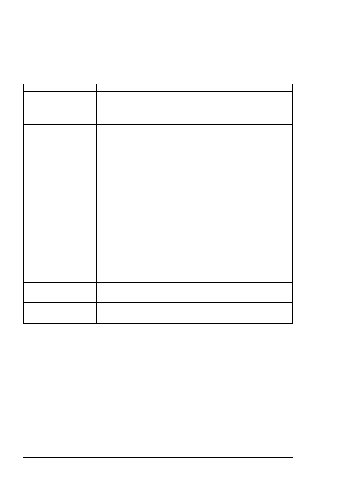
Table 4- 1. Required Adjustment
Replaced Unit/Part Adjustment Item and the Corresponding Menu
Printer Mechanism
C202 MAIN Board
Printhead
After disassembling and
reassembling the CR unit
Top frame
CR motor
Ink drain pad 1. EEPROM reset (Refer Chapter 6)
Note) * The adjusting program doesn’t run without inputting the customer data.
1. Customer data writing operation * :Input of Customer data
2. Initial ink charge :Ink charge
3. Head VH voltage input :Write to the Head voltage value
4. Head gap adjustment :Head GAP timing adjustment
5. Bi-d adjustment :Bi-d adjustment
1. Customer data writing operation * :Input of Customer data
2. Head VH voltage input :Write to the Head voltage value
3. Head gap adjustment :Head GAP timing adjustment
4. Bi-d adjustment :Bi-d adjustment
5. Ink drain pad replacement (Refer to Chapter 6 Maintenance.)
Note) Whenever C202MAIN board is replaced with a new one, all stored
data of EEPROM is lost. This means that the ink consumption
counter is lost. Therefore, whenever C202MAIN Board is replaced,
the printer must be equipped with a new ink cartridge. Above listed
adjustment items must be executed after replacing the ink cartridge
with a new one.
1. Customer data writing operation * :Input of Customer data
2. Initial ink charge :Ink charge
3. Head VH voltage adjustment :Write to the Head voltage value
4. Head angular adjustment :Head angular adjustment
5. Black/color head vertical adjustment:BK.-M Linear adjustment
6. Head gap adjustment :Head GAP timing adjustment
7. Bi-d adjustment :Bi-d adjustment
1. Platen gap adjustment
2. Customer data writing operation * :Input of Customer data
3. Head angular adjustment :Head angular adjustment
4. Black/color head vertical adjustment:BK.-M Linear adjustment
5. Head gap adjustment :Head GAP timing adjustment
6. Bi-d adjustment :Bi-d adjustment
1. Platen gap adjustment
2. Customer data writing operation * :Input of Customer data
3. Bi-d adjustment :Bi-d adjustment
1. Customer data writing operation * :Input of Customer data
2. Bi-d adjustment :Bi-d adjustment
4-
Rev. A
Page 4
Adjustment
3
4.1.2 Adjustment Tools
Table 4-2 shows the tools necessary to adjust this printer and the menus to be adjusted.
Table 4- 2. Adjustment Tools
Tools for adjusting Item to be adjusted
Program disk for adjustment
y DOS system
y GWBASIC
y Adjustment program
(Version J70C00E)
Thickness gauge (1.1 mm) Platen gap adjustment
The program disk for adjustment consis ts of the total of 40 files such as DOS system, GW BASIC.EXE,
and adjusting programs. The adjusting menus in the program are as shown below:
Customer data writing operation
Initial ink charge (Ink charge)
Head voltage adjustment
Head angular adjustment
Black/color head vertical adjustment
Head gap adjustment
Bi-d adjustment
Main menu
Input of Customer data
Adjustment/Print inspection
Change of center value
Input of comment
Change of date
Change of time
End
Select Menu :?_
Sub menu
Ink charge
Write to the Head voltage value
All adjustment
Head angular adjustment
BK.-M Linear adjustment
Head GAP timing adjustment
Bi-d adjustment
Print inspection
Ink discharge
Customer data change/End
Select Menu :?_
Print inspection sub menu
Input M/C No. : ?_
Black voltage value :
Color voltage value :
GOS paper print test
S.F. paper print test
O.Q.A print test
Cleaning
Return to the MENU
Letter paper print test
Select Menu :?_
Figure 4-1. Adjustment Program Menu
Select the item in the light gray shaded box to perform necessary adjustment. You can proceed to the sub
menu thorough the item in the dark gray shaded box in the bold line. Selecting “All adjustment” in the
sub menu enables you to perform the following adjus tments consec utively; “ Head angular adjustment”,
“BK.-M Linear adjustment” and “Head G AP adjustment/Bi-d adjustment” T his sec tion, however, only
refers to the individual adjustment methods.
CAUTION
During adjustment, values such as Customer data, head voltage value, head gap adjustment
;
value, and Bi-d adjustment value are written into the EEPROM at the specified timing as follows;
Customer data : At performing “Print Inspection”.
Head voltage value : When the “Return” key is pressed after entering the
values during “Write to the Head voltage value”
menu . The data is then transferred to the printer.
Bi-d/ Head gap adjustment value: At performing “Print Inspection”.
Rev. A
4-
Page 5
EPSON Stylus
4
&RORU
800
4.2 Adjustment
This section provides detailed information on how to perform the adjustments listed below and the notice
headed under “CAUTION”.
Platen gap adjustment
Customer data writing operation
Initial ink charge
Head voltage data writing operation
Head angular adjustment
BK-M Liner adjustment
Head gap adjustment
Bi-d adjustment
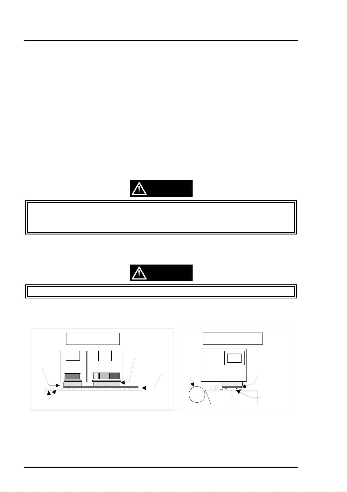
4.2.1 Platen Gap (PG) Adjustment
This adjustment is performed to obtain the appropriate gap between the head nozzle surface and the
platen, and is necessary when the parallelism adjust bushing has been set off the position during
disassembling and ass embling.
which is adjusted by inserting the thickness gauge between the head nozzle surface and platen then
turning the both left and right parallelism adjust bushings. This section describes how to adjust the PG gap
in the correct order along with cautions.
The standard value for the platen gap w ith this printer is 1.1 mm
,
CAUTION
Never touch the thickness gauge with your bare hand.
;
;
Make sure there is no oil, foreign object, and rust on the thickness gauge.
;
Check if your thickness gauge is not warped by checking it with the flat surface or new gauge.
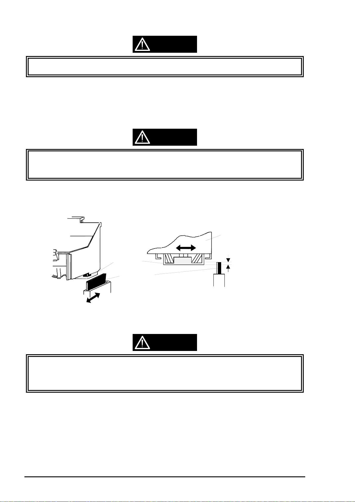
1. Set the PG lever to “+” (wide) position and shift the CR unit left. Then place the thickness gauge by
sliding it from the rear (PF roller side) into the front. In this time, don’t contact the thickness gauge to
the PF roller surface.
CAUTION
Be sure to level the thickness gauge when placing it onto the diamond cut rib on the platen plate.
;
2. Set the PG lever to “0” (narrow) position and shift the CR unit from left to right or vice versa by
holding the upper side of the timing belt.
Printer Mechanism
Viewed from the Left Side
Thickness Gauge
Black Head
Printer Mechanism
Viewed from the Front
Color Head
Thickness Gauge
PF Roller
Platen
Diamond Rib
Figure 4-2. Thickness Gauge Setting
4-
Diamond Rib
Rev. A
Page 6

Adjustment
5
g
3. Turn the left parallelism adjust bushing to the rear (narrower) step by step toward the left parallelism
adjust bushing set position, where the thickness gauge starts shif ting together with the CR unit. Then
shift the lever one step back to the front (wider) from the adjusted position.
Left Parallelsm Adjust Bushing
Rear side (Close)
Push to the rear
Viewed from the Left Frame Side
Figure 4-3. Left Parallelism Bushin
4. Hold the upper side of the timing belt and slide it to move the CR unit from right to left or vise versa to
confirm that the thickness gauge set on the platen does not move.
5. Return the PG lever toward “+” (wide) direction to remove the thick ness gauge, and slide the CR unit
right. Then place the thickness gauge by sliding it from the rear (PF roller side) into the f ront. During
this operation, don’t contact the PF roller surface with the thickness gauge.
6. Set the PG lever to the ”0” (narrower) position and shift the CR unit from left to right or vice vers a by
holding the upper side of the timing belt.
7. Turn the right parallelism adjust bushing to the rear step by step to the right parallelism adjust
bushing set position where the thickness gauge starts moving together with the CR unit. Then shift
the lever one step back to the front (wider) from the adjusted position.
8. Hold the upper side of the timing belt and slide it to move the CR to conf irm that the thick nes s gauge
set on the platen does not move.
Front side (Open)
Pull forward
Right Parallelism Adjust Bushing
Front side (Open)
Pull forward
Viewed from the Right Frame Side
Figure 4-4. Right Parallelism Bushing
9. Repeat the steps from 1 to 4 at the left end to confirm that the gap is correctly adjusted.
10. If the correct adjustment is confirmed, fix the left and right parallelism adjust bushings with the
screws (CBS, 3X6).
Rear side (Close)
Push to the rear
CAUTION
When fastening the screws, be careful not to dislocate bushings from the adjusted position
;
;
The tightening torque for the screws (CBS, 3X6) is 4.5 kg ~ 5.5 kg-cm.
Rev. A
4-
Page 7
EPSON Stylus
6
&RORU
800
CAUTION
;
After performing the PG gap adjustment, make sure that the “Cleaner Head” and head nose are in
contact with each other by the proper portion by following the instruction below.
11. Set the “PG Lever” to the “+” (wide) position.
12. Release the “CR Lock Lever” by turning it forward using the tweezers, and shif t the CR unit f rom the
CR home position to the right end of the “Front Paper Guide“. Then set the “Head Cleaner” to the
wiping/rubbing position by turning the larger gear of the “Pump Motor Reduction Gear” in counter
clock wise direction (forward).
CAUTION
Make sure that the “Change Cam” is set to the pump drive side during this operation. (Refer to
;
Figure 2-10 and 3-66 for the cam position.)
;
Stop turning the “Pump Reduction Gear” when you feel any resistance while turning the gear.
13. Slide the CR unit from left to right or vice versa by holding the upper side of the “Timing Belt” (or top
edge of the CR unit). Then check if the “Head Cleaner” and color head nose (metallic fram e part of
the head) come in contact with each other by 5 mm or more.
Carriage
Head Nose
Head Cleaner
Figure 4-5. Contact Area of the Color Head and Head Cleaner
Contact Area :
0.5 mm or more
CAUTION
When sliding the “Head Cleaner” to the metallic frame part of the head, be careful not to slide into
;
the head surface beyond the metal frame.
;
Check the “Cleaner Head” from the front left of the printer whether the contac t portion of the color
head and head cleaner is appropriate.
14. If you confirm the proper contact, return the large gear of the “Pum p Reduction Gears” in clock wise
direction to position the cleaner head under the “Sub Cable Holder” securely. If the portion is not
correct, check the positions for the “Head Cleaner” and “Pump Unit”, and replace the parts if
necessary.
15. Return the “CR unit” to the home position manually and set the “PG Lever” bac k to the “0” (narrow)
position.
4-
Rev. A
Page 8

Adjustment
7
4.2.2 Input of Customer Data
This operation is required when the C202 MAIN board is replaced. The program for this adjustment is
used to write the Customer data (set for each destination) into the EEPROM on the ASP C202 MAIN
board. If this program is not properly operated, it might caus e failure in reading CG data and installing
various types of utility using Bi-directional interface. The procedure for this operation is described below.
Customer data writing is programmed to be performed ahead of other adjustments. Therefore you
;
cannot proceed to any other adjustments without executing this operation first.
1. Set this program to FFD on your PC and turn the PC on.
2. The program automatically sets up and the following menu appears on the screen.
Stylus COLOR 800 J70C00E
Customer : Standard Customer DATA <
> 12-03-1996
****
3. Enter “1” for
4. Press
“ENTER”
Input Customer data
Adjustment/Print inspection
Changing of center value
Input of comment
Change of date
Change of time
END
Select Menu ?_
“Select menu :?”
key, and the menu below appears.
Stylus COLOR 800 J70C00E
Customer : Standard Customer DATA <
Input Customer data
Adjustment/Print inspection
Changing of center value
Input of comment
Change of date
Change of time
END
to select “
.....................
........................
..........................
..........................
Figure 4-6. Main Menu
Input of Customer data
.....................
........................
..........................
..........................
..............
................
..............
................
1
2
3
4
5
6
9
> 12-03-1996
****
1
2
3
4
5
6
9
” in the menu.
Select Menu : 1
Input the customer data
Memory-SW data (4col data) : ?
Figure 4-7. Input of Customer Data
5. Enter the 4-column code which corresponds to the destination for
and press
6. After performing necessary adjustments , store the setting values in the EEPROM on the C202 MAIN
board by selecting and performing
“ENTER”
key. The customer codes for each destination is listed below:
0000 : EAI, EAI (Latin)
0101 : EDG (NLSP) EDG (NLSP)
0001 : Europe Standard (EDG, EFS, EIS, EIB, EUL)
“Print Inspection”
in the sub menu.
Rev. A
“Memory-SW data (4 col data)”
4-
Page 9

EPSON Stylus
8
&RORU
800
4.2.3 Ink Charge
You must perform this operation after installing the “ASP Pr inthead” or ” ASP Printer Mec hanism ” in which
new “Printheads” are installed. “ASP Printheads” or “Printheads” installed in the “ASP Printer Mechanism ”
has shipping liquid filled in the cavity, and this operation is required to eject the liquid to r eplace it with the
ink. Therefore be sure to perform the initial ink charge operation whenever you replace the printhead,
since the lack of this oper ation might cause dot miss ing. The procedure and notes for this operation are
described below.
CAUTION
Avoid unnecessary initial ink charge operation, which consumes considerable amount of ink
;
(about one fifth of the ink cartridge capacity is consumed by this operation).
;
Do not turn the printer off before this program is completed. Otherwise, the ink dose not filled
enough in the cavity of the “Printhead”. in case of the power was turned off while this operation, do
this operation again by using this program.
;
This initial charge program is difference with the initial charge sequence which is carried out
automatically on the first power on time. This program carry out to chage the almost same value of
the ink which is used on the first power on initial charge sequence.
1. Set this program to FFD on your PC and turn the PC on.
2. The program automatically sets up and the following menu appears on the screen.
Stylus COLOR 800 J70C00E
> 12-03-1996
****
1
2
3
4
5
6
9
> 12-03-1996
****
1
2
3
4
5
6
9
” in the menu.
3. Enter “1” for
4. Press
“ENTER”
Customer : Standard Customer DATA <
Input Customer data
Adjustment/Print inspection
Changing of center value
Input of comment
Change of date
Change of time
END
Select Menu ?_
“Select menu : ?”
key, and the menu below appears.
Stylus COLOR 800 J70C00E
Customer : Standard Customer DATA <
Input Customer data
Adjustment/Print inspection
Changing of center value
Input of comment
Change of date
Change of time
END
to select “
.....................
........................
..........................
..........................
Figure 4-8. Main Menu
Input of Customer data
.....................
........................
..........................
..........................
..............
................
..............
................
Select Menu : 1
Input the customer data
Memory-SW data (4col data) : ?
Figure 4-9. Input of Customer Data
4-
Rev. A
Page 10

Adjustment
9
5. Enter the the 4-column code which corresponds to the destination for “Memory-SW data (4 col
data)” and press “ENTER” key. (See the code list on Page 4-6.)
6. Enter “2” for “Select menu : ?” to select “Adjustment/Print inspection” in the menu.
7. Press “ENTER” key, and the sub menu below appears.
Stylus COLOR 800 J70C00E
Customer : Standard Customer Data <
> 12-03-1996
****
Ink charge
Write to the Head voltage value
All adjustment
Head angular adjustment
BK.-M Linear adjustment
Head GAP timming adjustment
Bi-d adjustment
Print inspection
Ink discharge
Customer data change/End
Select Menu ?_
BI-D (center value 0,0)
Gap Timming (center value 0,0)
Figure 4-10. “Adjustment/Inspection” Sub Menu
8. Enter “0” for “Select menu : ?” to select “Ink charge” in the menu.
9. Press “ENTER” key, and the menu returns to the sub menu and the Initial ink charge sequence
starts. The Power LED on the control panel is blinking during this operation.
10. If you don’t proceed to the next adjustment, enter “9” for “Select menu : ?” to select “Customer
data change/End” in the current menu, and the menu returns to the main menu.
..............................
.......
..........................
.............
.............
.......
.....................
......................
........................
...........
0
1
2
3
4
5
6
7
8
9
11. Enter “9” for “Select menu : ?” then press “ENTER” to exit the program.
Rev. A
4-
Page 11

EPSON Stylus
0
&RORU
800
4.2.4 Write to the Head Voltage Value
This operation is required after installing the “ASP C202 MAIN board”, “ASP Printhead”, or “ASP Pr inter
Mechanism” in which new printheads are already installed. This operation is necessary to correct the head
drive pulse which differs from printhead to printhead depending on the piezoelectric elements
manufactured unevenly. This program allows you to write individual head voltage value into the EEPROM
on the C202 MAIN board. A failure in executing this program will result in inferior pr inting. The pr ocedure
for this operation is described below.
CAUTION
Take a note of the 5 columns head VH voltage value which is stamped on the left side of the
;
printhead before installing the new printhead.
;
“ASP Printer Mechanism” is equipped with the printhead. Do not forget to note the head VH
voltage value for the equipped printheads. The 5 columns head VH voltage value is stanpped on
label which is pasted on the printer mechanism package.
1. Set this program to FFD on your PC and turn the PC on.
2. The program automatically sets up and the following menu appears on the screen.
3. Enter “1” for
4. Press
“ENTER”
Stylus COLOR 800 J70C00E
Customer : Standard Customer DATA <
Input Customer data
Adjustment/Print inspection
Changing of center value
Input of comment
Change of date
Change of time
END
Select Menu ?_
“Select menu : ?”
key, and the menu below appears.
Stylus COLOR 800 J70C00E
Customer : Standard Customer DATA <
Input Customer data
Adjustment/Print inspection
Changing of center value
Input of comment
Change of date
Change of time
END
to select “
.....................
........................
..........................
..........................
Figure 4-1 1. Main Menu
Input of customer data
.....................
........................
..........................
..........................
..............
................
..............
................
> 12-03-1996
****
1
2
3
4
5
6
9
> 12-03-1996
****
1
2
3
4
5
6
9
” in the menu.
Select Menu : 1
Input the customer data
Memory-SW data (4col data) : ?
-
4-1
Rev. A
Page 12

Adjustment
5. Enter the 4-column code which corres ponds to the destination for “Memory-SW data (4 col data)”
and press “ENTER” key. (See the code list on Page 4-6.)
6. Enter “2” for “Select menu : ?” to select “Adjustment/Print inspection” in the menu.
7. Press “ENTER” key, and the sub menu below appears.
Stylus COLOR 800 J70C00E
Customer : Standard Customer Data <
> 12-03-1996
****
Ink charge
Write to the Head voltage value
All adjustment
Head angular adjustment
BK.-M Linear adjustment
Head GAP timming adjustment
Bi-d adjustment
Print inspection
Ink discharge
Customer data change/End
Select Menu ?_
BI-D (center value 0,0)
Gap Timming (center value 0,0)
Figure 4-13. “Adjustment/Inspection” Sub Menu
8. Enter “1” for “Select menu : ?” to select “Write to the Head voltage value” in the menu.
9. Press “ENTER” key, and the following appears.
<<<< Write the HEAD Voltage value>>>>
Black Head voltage
Black voltage value (5chr. ID data (ex.18A09)) :
..............................
.......
..........................
.............
.............
.......
.....................
......................
........................
...........
0
1
2
3
4
5
6
7
8
9
----Voltate value---------------------Black voltate value :
Color voltage value
“Write to the Head Voltage Value”
10. Input the correct head voltage with 5 colums and check if the head voltage value was input on the
confirmation m enu which is shown on the screen. If correc t, press “ENTER” key. If incorrect, press
“SPACE” key and replace the incorrect value with the correct one.
Rev. A
:
Figure 4-14.
4-1 1
Page 13

EPSON Stylus
2
&RORU
800
<<<<Write the Head Voltage value>>>
Black Head voltage
Black Head voltage value (5chr. ID data (ex.18A09)):24B16
Color Head voltage voltage
Color Head voltage value (5chr. ID data (ex. 18A09)): 14B14
OK? <Space> to retry <Return> to write the value & return to the MENU
------Voltage value------------------Black voltage :
Color voltage :
Figure 4-15. Write to the Head Voltage Value (2)
11. After inputting the correct values, the head voltage values are s tored in the EEPROM on the C202
MAIN board by pressing the “ENTER” key, and the sub menu appears.
12. If ther e is no more adjustment to be perf ormed, enter “9” for “Select menu : ?” to select “Customer
data change/End” in the sub menu, then press “ENTER” k ey, and the menu r eturns to the main
menu.
13. Enter “9” for “Select menu : ?”, then press the “ENTER” key to exit the program.
4-1
Rev. A
Page 14

Adjustment
3
4.2.5 Head Angular Adjustment
This adjustment must be operated when replacing the printhead or dis as sembling and assem bling the CR
unit in order to attach the printheads at the proper angular on the level. This adj ustment , perf ormed on
physical basis, is accomplis hed by moving the head angular adjustm ent lever ass embled to the f ront s ide
of the CR unit. You can identify and adjust the slant according to the result on the test pattern output
during the adjusting program. Therefore there is no value to be written into the EEPROM on the C202
MAIN board. The adjustment procedure is as follows;
1. Set this program to FFD on your PC and turn the PC on.
2. The program automatically sets up and the following menu appears on the screen.
Stylus COLOR 800 J70C00E
Customer : Standard Customer DATA <
> 12-03-1996
****
3. Enter “1” for
4. Press
“ENTER”
Input Customer data
Adjustment/Print inspection
Changing of center value
Input of comment
Change of date
Change of time
END
Select Menu ?_
“Select menu : ?”
key, and the menu below appears.
Stylus COLOR 800 J70C00E
Customer : Standard Customer DATA <
Input Customer data
Adjustment/Print inspection
Changing of center value
Input of comment
Change of date
Change of time
END
to select “
.....................
........................
..........................
..........................
Figure 4-16. Main Menu
.....................
........................
..........................
..........................
1
..............
................
Input of customer data
..............
................
2
3
4
5
6
9
> 12-03-1996
****
1
2
3
4
5
6
9
” in the menu.
Select Menu : 1
Input the customer data
Memory-SW data (4col data) : ?
Figure 4-17. Input of Customer Data
5. Enter the suitable 4 columns data for
Regarding the suitable 4 columns data, refer the page 4-6.
6. Enter “2” for
Rev. A
“Select menu : ?”
“Memory-SW data (4 col data)”
to select
and press
“Adjustment/Print inspection”
“ENTER”
in the menu.
key.
4-1
Page 15

EPSON Stylus
4
7. Press “ENTER” key, and the menu below appears.
&RORU
800
Stylus COLOR 800 J70C00E
Customer : Standard Customer Data <
> 12-03-1996
****
Ink charge
Write to the Head voltage value
All adjustment
Head angular adjustment
BK.-M Linear adjustment
Head GAP timming adjustment
Bi-d adjustment
Print inspection
Ink discharge
Customer data change/End
Select Menu ?_
BI-D (center value 0,0)
Gap Timming (center value 0,0)
Figure 4-18. “Adjustment/Inspection” Sub Menu
8. Enter “3” for “Select menu : ?” to select “Head angular adjustment” in the menu, then press
“ENTER” key.
9. Enter a dummy number in 3 digits such as “000” or “111” for “MC No.”, and the head angular
adjustment pattern is printed out.
..............................
.......
..........................
.............
.............
.......
.....................
......................
........................
...........
0
1
2
3
4
5
6
7
8
9
CAUTION
When the MC number is entered, the head angular adjustment pattern is printed and the following
;
message appears on the screen;
“Space“ key to print again (“Return” to the MENU) (“0” key to cleaning/ “E” key to
escape to the error)
If you identify missing dots on the pattern, you can enter “0” to reprint the adjustment pattern after
performing the head cleaning. The black and color head cleaning is executed either individually or
together, which you can select. This cleaning is same as CL2 cleaning.
10. Look at the output to chec k if the lines are printed at the regular interval. Figure below shows how to
move the head angular adjust lever to adjust different misalignment patterns for each head.
Black Printing Color Printing
Move the lever
right.
Correct pattern
Move the lever
left.
Move the lever
right.
Correct pattern
Move the lever
left.
Head Angular Adjustment Lever
Figure 4-19. Use of the Head Angular Adjust Lever
4-1
Rev. A
Page 16

Adjustment
5
CAUTION
;
Slant changes with a unit of 0.02 mm by moving the head angular adjustment lever one step.
11. Af ter adjus ting the angular adj ustment lever by looking the adjustment pattern s heet, pres s “SPACE”
key to print another adjustment pattern sheet.
12. If the lines in the new adjustment patterns are aligned at the r egular interval, press “ENTER” key,
and the sub menu appears on the screen.
13. If you don’t proceed to the next adjustment, enter “9” for “Select menu : ?” to select “Customer
data change/End” in the menu, then press “ENTER” key to return to the main menu.
14. Enter “9” for “Select menu : ?” then press “ENTER” key to exit the program.
Rev. A
4-1
Page 17

EPSON Stylus
6
&RORU
800
4.2.6 BK.-Linear Adjustment
BK.-M Linear adjustment is required when replacing the printhead or disassem bling and assembling the
CR unit, and is performed to adjust the vertical position of the color head by using the black head for the
basis. This adjustment, which depends on the physical operation, is accomplished by moving the head
vertical adjust lever assembled to the right side of the CR unit. By running this program, the head vertical
adjustment pattern is printed to identif y the misalignment caused by the vertical gap between the Black
Head and Color Head. According to the printed pattern, adjust the gap by moving the head vertical
adjustment lever. Therefore this adjustment has no value to be written into the EEPROM on the C202
MAIN board. The adjustment procedure is as follows;
1. Set this program to FFD on your PC and turn the PC on.
2. The program automatically sets up and the following menu appears on the screen.
Stylus COLOR 800 J70C00E
Customer : Standard Customer DATA <
> 12-03-1996
****
3. Enter “1” for
4. Press
“ENTER”
Input Customer data
Adjustment/Print inspection
Changing of center value
Input of comment
Change of date
Change of time
END
Select Menu ?_
“Select menu : ?”
key, and the menu below appears.
Stylus COLOR 800 J70C00E
Customer : Standard Customer DATA <
Input Customer data
Adjustment/Print inspection
Changing of center value
Input of comment
Change of date
Change of time
END
to select
.....................
........................
..........................
..........................
Figure 4-20. Main Menu
“Input of Customer data”
.....................
........................
..........................
..........................
..............
................
..............
................
1
2
3
4
5
6
9
> 12-03-1996
****
1
2
3
4
5
6
9
in the menu.
Select Menu : 1
Input the customer data
Memory-SW data (4col data) : ?
Figure 4-21. Input of Customer Data
5. Enter the 4-column code which corres ponds to the destination for
and press
6. Enter “2” for
4-1
“ENTER”
“Select menu : ?”
key. (See the code list in Page 4-6.)
to select
“Adjustment/Print inspection”
“Memory-SW data (4 col data)”
in the menu.
Rev. A
Page 18

7
7. Press “ENTER” key, and the sub menu below appears.
Stylus COLOR 800 J70C00E
Customer : Standard Customer Data <
> 12-03-1996
****
Adjustment
Ink charge
Write to the Head voltage value
All adjustment
Head angular adjustment
BK.-M Linear adjustment
Head GAP timming adjustment
Bi-d adjustment
Print inspection
Ink discharge
Customer data change/End
Select Menu ?_
BI-D (center value 0,0)
Gap Timming (center value 0,0)
Figure 4-22. “Adjustment/Inspection” Sub Menu
8. Enter “4” for “Select menu : ?” to select “BK.-M Linear adjustment” in the menu.
9. Press “ENTER” key, and the printer prints the adjustment pattern in black and magenta ink.
10. Look at the output to check if the lines f or black and magenta ar e mos t closely aligned. Figure below
shows how to move the head vertical adjust lever to adjust different misalignment patterns.
Black Col or Bl ack
Black Col or Bl ack
..............................
.......
..........................
.............
.............
.......
.....................
......................
........................
...........
0
1
2
3
4
5
6
7
8
9
Paper feed
direction
Move the Lever forward
Move the Lever backward
Figure 4-23. Use of the Head Vertical Adjust Lever
Paper feed
direction
Head Vertical Adjustment
Lever
CAUTION
Slant changes with a unit of 0.02 mm by moving the head angular adjust lever one step.
;
11. After adjust the head vertical adjustment lever by looking the adjustment pattern sheet, press
“SPACE” key to print adjustment pattern sheet agin.
12. If the new adjustment patterns is aligned within the specific ation, press “ENTER” key, and the sub
menu appears on the screen.
13. If ther e is no adjus tm ent to be perfor m ed, enter “9” for “Select menu : ?” to select “Customer data
change/End” in the menu, then press “ENTER” key to return to the main menu.
14. Enter “9” for “Select menu : ?” then press “ENTER” key to exit the program.
Rev. A
4-1
Page 19

EPSON Stylus
8
&RORU
800
4.2.7 Head GAP Timing Adjustment
Head GAP Timing Adjustment is requir ed when the C202 MAIN board or the Printhead is replaced (or
disassembling and assem bling the CR unit) to correct the vertic al misalignment c aused by different print
timings between black and color ink s. This adjustment, s ame as f or the Bi-d adjustment, is perf ormed by
entering the adjusting value. Therefore the adjus ting values are s tored in the EEPRO M on the C202 MAIN
board. The adjusting procedure is described below.
1. Set this program to FFD on your PC and turn the PC on.
2. The program automatically sets up and the following menu appears on the screen.
Stylus COLOR 800 J70C00E
Customer : Standard Customer DATA <
> 12-03-1996
****
3. Enter “1” for
4. Press
“ENTER”
Input Customer data
Adjustment/Print inspection
Changing of center value
Input of comment
Change of date
Change of time
END
Select Menu ?_
“Select menu : ?”
key, and the menu below appears.
Stylus COLOR 800 J70C00E
Customer : Standard Customer DATA <
Input Customer data
Adjustment/Print inspection
Changing of center value
Input of comment
Change of date
Change of time
END
to select
.....................
........................
..........................
..........................
Figure 4-24. Main Menu
“Input of Customer data”
.....................
........................
..........................
..........................
..............
................
..............
................
1
2
3
4
5
6
9
> 12-03-1996
****
1
2
3
4
5
6
9
in the menu.
Select Menu : 1
Input the customer data
Memory-SW data (4col data) : ?
Figure 4-25. Input of Customer Data
5. Enter the 4-column code which corres ponds to the destination for
and press
6. Enter “2” for
4-1
“ENTER”
“Select menu : ?”
key. (See the code list in Page 4-6.)
to select
“Adjustment/Print inspection”
“Memory-SW data (4 col data)”
in the menu.
Rev. A
Page 20

7. Press “ENTER” key, and the sub menu below appears.
Stylus COLOR 800 J70C00E
Customer : Standard Customer Data <
> 12-03-1996
****
Adjustment
Ink charge
Write to the Head voltage value
All adjustment
Head angular adjustment
BK.-M Linear adjustment
Head GAP timming adjustment
Bi-d adjustment
Print inspection
Ink discharge
Customer data change/End
Select Menu ?_
BI-D (center value 0,0)
Gap Timming (center value 0,0)
Figure 4-26. “Adjustment/Inspection” Sub Menu
8. Enter “5” for “Select menu : ?” to select “Head GAP timing adjustment” in the menu.
9. Press “ENTER” key, the menu below appears, along with 6 adjustment patterns (3 for 200 cps and 3
for 100 cps) printed in black and magenta.
Monitor display
Adjustment area (-30 to 30)
200 CPS : ?_
..............................
.......
..........................
.............
.............
.......
.....................
......................
........................
...........
0
1
2
3
4
5
6
7
8
9
200 cps : -2
200 dps : 0
200 cps : 2
100 cps : -2
100 cps : 0
200 cps : 2
Adjustment pattern
Figure 4-27. Head Gap Adjustment Patterns
Rev. A
4-19
Page 21

EPSON Stylus
0
&RORU
800
10. Look at the output to check if the lines f or black and color are m ost closely aligned. If not, input the
proper value to adjust the misalignment according to the result, as shown in the figure below.
Black
Color
Black
Value to Enter:
Minus
Direction in which
the paper is fed
Value to Enter:
Black
Color
Black
Plus
Figure 4-28. Adjusting Value Determination
CAUTION
The printed vertical line shift about 0.07mm by inputting “4” on 200 cps adjustment mode and “2”
;
on 100cps adjustment mode.
11. If the value input is incorrect, enter the correct value after pressing the “SPACE” key and press
“ENTER” key to set the values, then the menu returns to the sub menu.
12. Enter “7” for “Select menu : ?” and press “ENTER” key to proceed to “Print Inspection” in the sub
menu in order to check how the set values affect to the outcome. The menu appears is as follows;
Input M/C No. : ?
M/C No. :
Black voltage value :
Color voltage value :
Figure 4-29.
Setting Menu (1) for Print Inspection
Input M/C No. : ?
Black voltage value : 24B16
Color voltate value : 14B14
OK? ('Return' to NEXT) :
M/C No. :
Black voltage value :
Color voltage value :
Figure 4-30.
Setting Menu (2) for Print Inspection
4-2
Rev. A
Page 22

Adjustment
g
13. Follow the menu by entering a dummy M/C No. in 3 digits and black/color head voltages
corresponding the installed printheads, then press “ENTER” key, and the menu below appears.
14. If the value input is incorrect, press “SPACE” and enter the correct value. If the input values are
Stylus COLOR 800 J70C00E
Customer : Sstandard cistpmer DATA <
> 12-03-0996
****
GOS paper print test
S.F. paper print test
O.Q.A. print test
Cleaning
Return to the MENU
Letter paper print test
Select Menu ?_
MC/No. : 000
Black voltage value : 24B16
Color voltage value : 14B14
correct, proceed to the menu shown below by pressing the “ENTER” key.
15. Enter “2” for “Select menu : ?” to select “S.F. paper print test” in the menu, then press “ENTER”
key, and the printer outputs the result of the head gap timing adjustment , along with the results of
other adjustments.
16. Look at the output to check if the lines are most closely aligned. If not, enter “9” for “Select menu :
?” to select “Return to the MENU”, then press “ENT ER” key to return to the sub menu.
.................................
Settin
.......................
........................
...........................
........................
.......................
Figure 4-31.
Menu (3) for Print Inspection
1
2
5
0
9
7
17. Repeat the steps fr om 8 to 16 until the output is satisfac tory, then enter “9” for “Select menu : ?” in
the menu indicated in Figure 4-31 and press “ENTER” key to return to the sub menu.
18. If ther e is no adjus tm ent to be perfor m ed, enter “9” for “Select menu : ?” to select “Customer data
change/End” in the menu, then press “ENTER”.
19. Enter “9” for “Select menu : ?” to exit the program.
Rev. A
4-21
Page 23

EPSON Stylus
2
&RORU
800
4.2.8 Bi-d adjustment
Bi-d adjustment is required when the printer is under the following conditions; the printer m echanism is
replaced, the C202 MAIN board is replaced, the CR unit is disass embled and assembled, top f rame is
replaced, and the CR motor is disassembled. This program enables you to align the vertical line by
adjusting the print timing in the Bi-directional black printing mode. The adjustment value is stored in the
EEPROM on the C202 MAIN board. The adjusting procedure is described below.
1. Set this program to FFD on your PC and turn the PC on.
2. The program automatically sets up and the following menu appears on the screen.
Stylus COLOR 800 J70C00E
Customer : Standard Customer DATA <
> 12-03-1996
****
3. Enter “1” for
4. Press
“ENTER”
Input Customer data
Adjustment/Print inspection
Changing of center value
Input of comment
Change of date
Change of time
END
Select Menu ?_
“Select menu : ?”
key, and the menu below appears.
Stylus COLOR 800 J70C00E
Customer : Standard Customer DATA <
Input Customer data
Adjustment/Print inspection
Changing of center value
Input of comment
Change of date
Change of time
END
to select
.....................
........................
..........................
..........................
Figure 4-32. Main Menu
“Input of Customer data”
.....................
........................
..........................
..........................
..............
................
..............
................
1
2
3
4
5
6
9
> 12-03-1996
****
1
2
3
4
5
6
9
in the menu.
Select Menu : 1
Input the customer data
Memory-SW data (4col data) : ?
Figure 4-33. Input of Customer Data
5. Enter the 4-column code which corres ponds to the destination for
and press
6. Enter “2” for
4-2
“ENTER”
“Select menu : ?”
key. (See the code list in Page 4-6.)
to select
“Adjustment/Print inspection”
“Memory-SW data (4 col data)”
in the menu.
Rev. A
Page 24

3
7. Press “ENTER” key, and the sub menu below appears.
Stylus COLOR 800 J70C00E
Customer : Standard Customer Data <
> 12-03-1996
****
Adjustment
Ink charge
Write to the Head voltage value
All adjustment
Head angular adjustment
BK.-M Linear adjustment
Head GAP timming adjustment
Bi-d adjustment
Print inspection
Ink discharge
Customer data change/End
Select Menu ?_
BI-D (center value 0,0)
Gap Timming (center value 0,0)
Figure 4-34. “Adjustment/Inspection” Sub Menu
8. Enter “6” for “Select menu : ?” to select “Bi-d adjustment” in the menu.
9. Press “ENTER” key, and the menu below appears, along with 6 adjustment patterns, 3 for 267 cps
and 3 for 200 cps, are printed in black as shown in Figure 4-35.
Monitor display
Adjustment area (-30 to 30)
267 CPS : ?_
..............................
.......
..........................
.............
.............
.......
.....................
......................
........................
...........
0
1
2
3
4
5
6
7
8
9
267 cps Bi-D : -4
267 cps Bi-D : 0
267 cps Bi-D : 4
200 cps Bi-D : -2
200 cps Bi-D : 0
200 cps Bi-D : 2
Figure 4-35. Bi-d Adjustment Patterns
Rev. A
4-2
Page 25

EPSON Stylus
&RORU
800
10. Look at the output to check if the lines are most closely aligned. If not, adjust the misalignment
referring to the output result, as shown in the figure below.
Direction in which
the paper is fed
Value to Enter:
Minus
Value to Enter:
Plus
Figure 4-36. Adjusting Value Determination
CAUTION
As you change the value with a unit of 4 for 267cps or 2 for 200 cps, the slant moves
;
approximately 0.07 mm or 0.035 mm, respectively.
;
The printed vertical line shift about 0.07mm by inputting “4” on 267cps adjustment mode . On the
200cps adjustment mode, by inputting “2” , the printed vertical line shift about 0.035mm..
11. If the value input is incorrect, enter the correct value after pressing the “SPACE” key and press
“ENTER” key to set the values, then the menu returns to the sub menu.
12. Enter “7” for “Select menu : ?” then press “ENTER” key to proceed to the “Print Inspection” in the
sub menu, in order to check how the set values affec t to the outcome. The following appears on the
screen.
Input M/C No. : ?
M/C No. :
Black voltage value :
Color voltage value :
Figure 4-37.
Setting Menu (1) for Print Inspection
13. Follow the menu by entering a dummy M/C No. in 3 digits, black voltage, and color voltage
corresponding the installed printheads, then press “ENTER” key, and the following menu appears.
Input M/C No. : ?
Black voltage value : 24B16
Color voltate value : 14B14
OK? ('Return' to NEXT) :
M/C No. :
Black voltage value :
Color voltage value :
Figure 4-38.
SettingMenu(2)forPrintInspection
4-24
Rev. A
Page 26

Adjustment
5
14. If the value input is incorrect, press “SPACE” and enter the correct value. If the input values are
correct, press the “ENTER” key to proceed to the menu shown below.
Stylus COLOR 800 J70C00E
Customer : Sstandard cistpmer DATA < > 12-03-0996
GOS paper print test
S.F. paper print test
O.Q.A. print test
Cleaning
Return to the MENU
Letter paper print test
Select Menu ?_
MC/No. : 000
Black voltage value : 24B16
Color voltage value : 14B14
Figure 4-39 Setting Menu (3) for Print Inspection
.................................
.......................
........................
...........................
........................
.......................
****
1
2
5
0
9
7
15. Enter “2” for “Select menu : ?” to select “S.F. paper print test” in the menu, then press “ENTER”
key, and the printer outputs the result of the Bi-d adjustment, along with the results of other
adjustments.
16. Look at the output to check if the alignment is satisfactor y. If not, enter “9” for “ Select menu : ?” to
select “Return to the MENU”, then press “ENTER” key.
17. Repeat the steps 8 to 16 until the output is satisfactor y, then enter “9” for “Select menu : ?” in the
menu shown in Figure 4-39 and press “ENTER” key to return to the sub menu.
18. If there is no more adjustments to be performed, enter “9” for “Select menu : ?” to select
“Customer data change/End” in the menu, then press “ENTER”.
19. Enter “9” for “Select menu : ?” to exit the program.
Rev. A
4-2
 Loading...