

Page 1

Chapter 2
Operating Principles
2.1 Overview................................................................................................................2-1
2.2 Printer Mechanism Operating Principles ...........................................................2-1
2.2.1 General Description ...............................................................................................................2-1
2.2.2 Printing Mechanism ...............................................................................................................2-2
2.2.2.1 Printing Process ........................................................................................................2-3
2.2.2.2 Printing Methods........................................................................................................2-3
2.2.3 Carriage (CR) Mechanism...................................................................................................... 2-4
2.2.4 Paper Feed Mechanism..........................................................................................................2-5
2.2.5 Platen Gap (PG) Adjust Mechanism ..................................................................................... 2-6
2.2.6 CR Lock Mechanism ..............................................................................................................2-6
2.2.7 ASF Mechanism...................................................................................................................... 2-7
2.2.8 Ink System...............................................................................................................................2-9
2.2.8.1 Pump Mechanism.................................................................................................... 2-10
2.2.8.2 Capping Mechanism................................................................................................ 2-12
2.3 Electrical Circuit Operation Principles.............................................................2-13
2.3.1 C202 PSB/PSE board............................................................................................................ 2-13
2.3.2 C202 MAIN Control Board....................................................................................................2-15
2.3.2.1 Printhead Driver Circuit ........................................................................................... 2-16
2.3.2.2 Reset Circuits..........................................................................................................2-18
2.3.2.3 Motor Driver Circuits................................................................................................ 2-19
2.3.2.4 Sensor Circuits........................................................................................................2-20
2.4 Ink System Management....................................................................................2-21
2.4.1 Ink System Operations.........................................................................................................2-21
2.4.2 Timers and Counters............................................................................................................2-22
2.4.3 Ink System Sequence...........................................................................................................2-23
Page 2

Operating Principles
2.1 Overview
This chapter provides information on the printer mechanism, electrical circuit, and ink system. The
operating principles for each mechanism in the printer mechanism is described individually. The
description for the electrical circuit is divided into 2 parts; C202 PSB/PSE board and C202 MAIN board.
2.2 Printer Mechanism Operating Principles
2.2.1 General Description
This printer is m ainly composed of the printing m echanism , paper feed m echanism , car riage m echanism ,
pump mechanism, and ASF mechanism. There are 3 motors, carriage motor (CR motor), paper feed
motor, (PF motor) and pump motor. Table 2-1 shows each motor and corresponding units and assem blies
driven.
Table 2-1. Motor and Unit/Assembly Driven
Motor Unit/Assembly driven
PF motor PF roller assembly, CR lock lever
CR motor CR unit, Capping unit
Pump motor Pump unit, Capping unit, Wiper, ASF unit
When the PF Motor rotates clockwise, the torque is us ed to drive PF Roller assembly and release CR
Lock Lever, while the torque is used to set the CR Lock Lever when the PF Motor rotates
counterclockwise.
The CR motor transmit the torque via Timing Belt to shift the CR unit in the both right and lef t direc tions in
parallel with the Platen. The torque from the Pump Motor, switched by the disengage mechanism, is
transmitted to the ASF and the Pump m otor. The figure below shows the structure bloc k of the printer
mechanism .
CR Motor
Pump Motor
PF Motor
Carriage Mechanism
Slider Mechanism
Disengage Mechanism
Figure 2-1. Printer Mechanism Block Diagram
Print Mechanism
Black
Pump Mechanism
ASF Mechanism
Paper Feed Mechanism
CR Lock Mechanism
Color
Rev. A
2-1
Page 3
EPSON Stylus
2
&2/25
800
2.2.2 Printing Mechanism
The printing method used for this printer is O n-demand ink jet s ystem, same as for other EPSON ink jet
printers. This printer, however, uses newly designed MACH Head, which ensures a high level of printing
quality at a higher speed. This printer is equipped with separate printheads of the same type; one for black
and one for each of the three colors (magenta, cyan, and yellow). Quick penetration, the type of black and
color ink, is also im proved for this pr inter, which enables the users to have the printing im age in the high
quality on the normal paper.
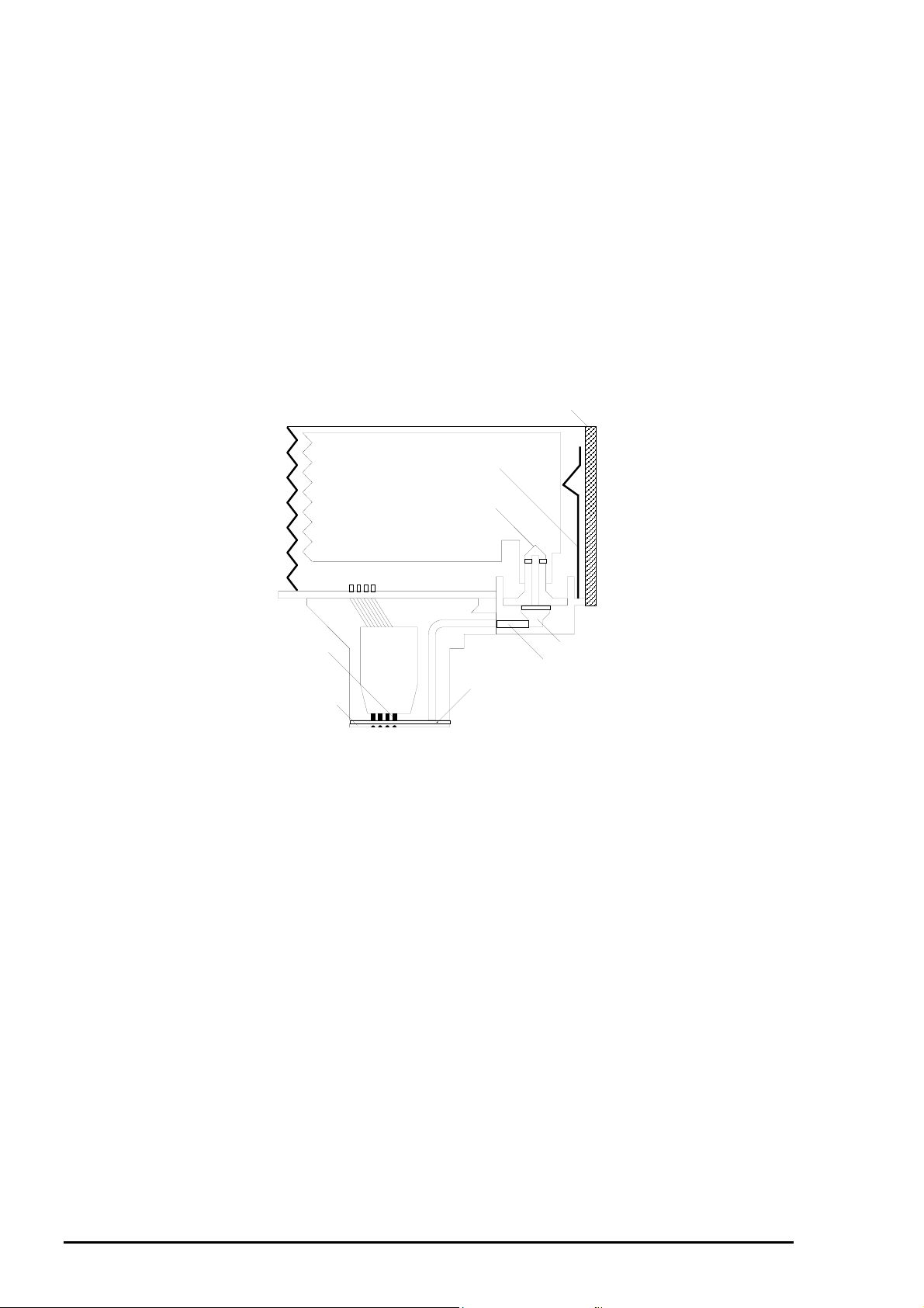
Printhead
The black and color printheads for this printer use the newly designed MACH Head (E-CHIPS Head).
The structure of the printhead is the same as for previous CHIPS Head except for the nozzle
configuration. The Black Head for this printer has 128 nozzles (32 nozzles for each of 4 rows ) which
is as twice as many as previous EPSON ink jet printers , and the Color Head has 192 nozzles (32
nozzles for each of 6 rows) which is 3 times as many as previous EPSON ink jet printer s. Theref ore
printing quality as well as the speed for this printer is higher than ever. The nozzle structure for this
printhead is shown in the figure below.
Printhead Driver Board
Ink Cartridge Sensor Lever
Cartridge Needle
(Ink Cartridge)
PZT
Cavity
Nozzle Plate
Filter
Ink Tube
Figure 2-2. Printhead Structure
PZT
PZT is an abbreviation of the Piezo Electric Element. Print signal from C202 MAIN board is sent
through the driver board on the Printhead unit and to the PZT. Then, the PZT pushes the top cavity
which has ink stored, and makes the ink discharge from each nozzle located on the nozzle plate.
Cavity Set
Ink which is absorbed from ink cartridge goes through the filter and will be stored temporarily in
this tank, which is called “cavity” unit driven by PZT.
Nozzle Plate
The board with nozzle holes on the Printhead surface is called Nozzle Plate.
Filter
When the ink cartridge is installed, if any dirt or dust around the cartridge needles are absorbed
into the head inside, there is a great possibility of causing nozzle clog and disturbance of ink flow
and finally causing alignment failure and dot-missing. In order to prevent this, filter is set at
cartridge needle below and ink is once filtered here.
2-
Rev. A
Page 4
Operating Principles
3
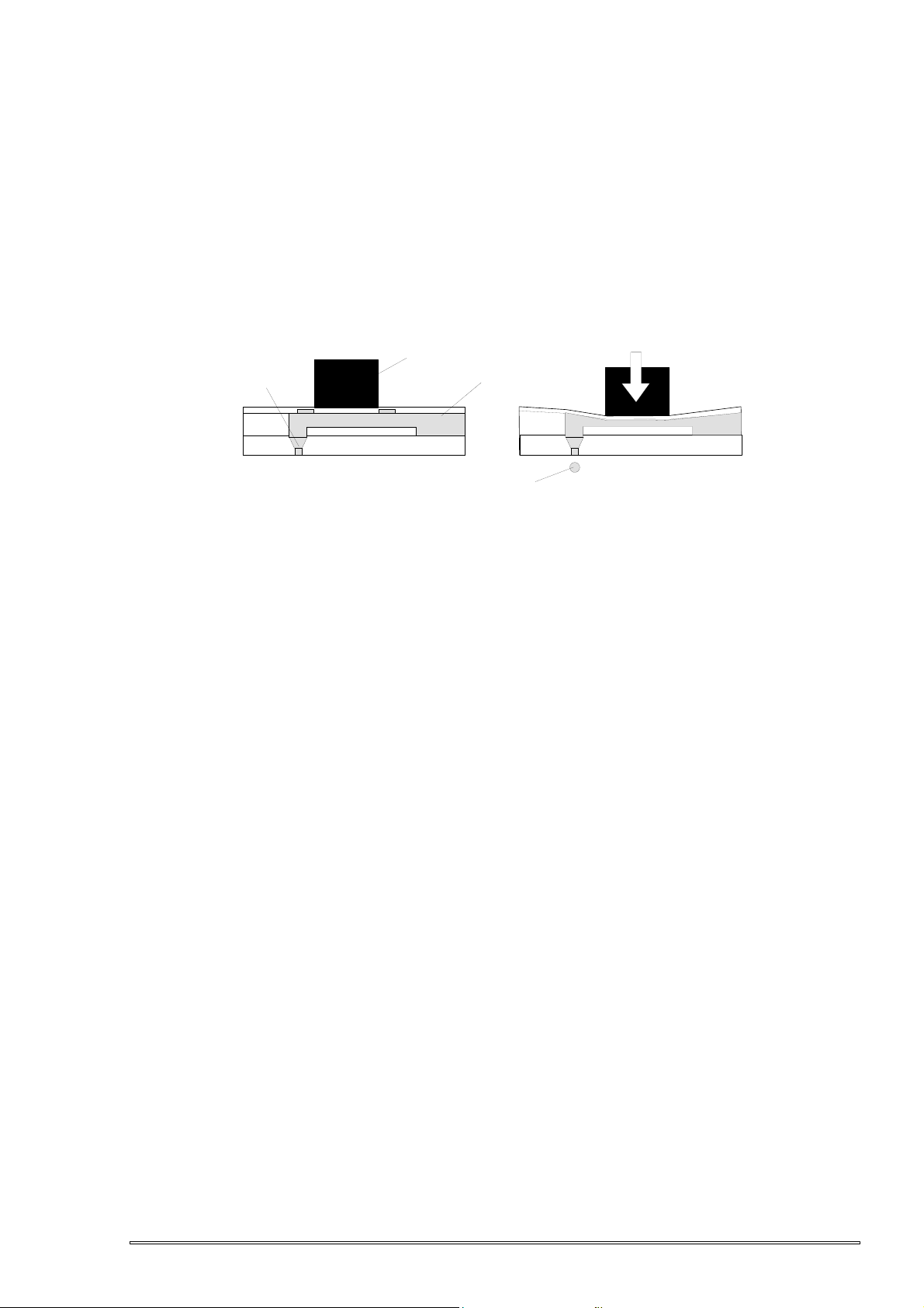
2.2.2.1 Printing Process
Steps bellow describes how the on-demand ink jet system ejects the ink from each nozzle in the
printhead.
<
Step 1>Normal state
When the print signal is not output, PZT also dose not move in the waiting state (normal state).
<
Step 2>Ejecting state
When the print signal is output from the C202 MAIN board, Nozzle selector IC mounted on the head driver
board latches the data once by 1-byte unit. Appropriate PZT latched by nozzle selector is pushed in to the
cavity by applying common voltage from the C202 MAIN board. By this operation, ink that is stored in the
cavity pops out from nozzles.
Nozzle
Normal State
Piezo
Cavity
Ejected ink
Ejecting State
Figure 2-3. Print Process
During the ink charging or cleaning operation, the ink left in the cavity is vacuumed out by the Pump
mechanism via Capping unit, then is ejected to the waste ink tank . The cavity is refilled with ink from the
Ink Cartridge during the printing or other operations. The viscosity of the ink tends to change according to
the temperatures around the heads, and the change in vis cosity results in the low printing quality. This is,
however, avoided by attaching the thermistor directly to the driver circuit board. It is used to determ ine the
proper drive pulse automatically according to the detected temperature.
2.2.2.2 Printing Methods
This printer has 3 kinds of diff erent dot to com pos e the print im age; Norm al dot, Double f iring Norm al dot,
and Micro dot. Each dot is selected to control printing depending on the conditions s uch as the paper type
and the print resolution set through the printer driver.
Normal dot / Double Firing Normal dot printing mode
Normal dot/Double firing Normal dot printing modes are available for the both black and color
printings. Normal dot printing mode is designed to form single dot with 2 head drive pulses. With this
mode, the dot diameter is expanded to solve the white banding problem which occurs during solid
printing at 360 dpi. This printer is, however, designed to use less ink than other printers do to perform
printing at 1440 dpi, the maximum solution on the horizontal line. Therefore the Double firing Normal
dot and Normal dot used for this printer is considered equivalent to the Normal dot mode and Micro
dot mode used for previous ink jet printers respectively. Double firing Normal dot mode is normally
selected for printing at 360 dpi, and the Normal dot mode is used for printing in 720 X 360 dpi or 720
dpi X 720 dpi, depending on the paper type.
EPSON Micro dot printing
Both black and color printings can be performed in the Micro dot printing mode. In the Normal dot
printing, one dot is formed with 2 pulses. On the other hand, EPSON micro dot printing mode forms
one dot with single pulse using less ink. As mentioned above, the Micro dot printing for this printer is
controlled to use less ink to create images at 1440 dpi, the maximum solution on the horizontal line.
This mode is used for printing at 720 dpi or 1440 dpi by controlling the firing duty of the ink.
Micro Weave Printing
This function is developed to enhance quality in graphic image by eliminating white banding which
occurs on each line. This printer is equipped with a new micro weave printing mode and is controlled
to form a horizontal line using 2 different types of nozzle. With this mode, the printer can prevents
color inks from mixing with each other before drying and can provide clearer colors in the output. The
Micro Weave printing can be selected through the printer driver.
Rev. A
2-
Page 5
EPSON Stylus
4
&2/25
800
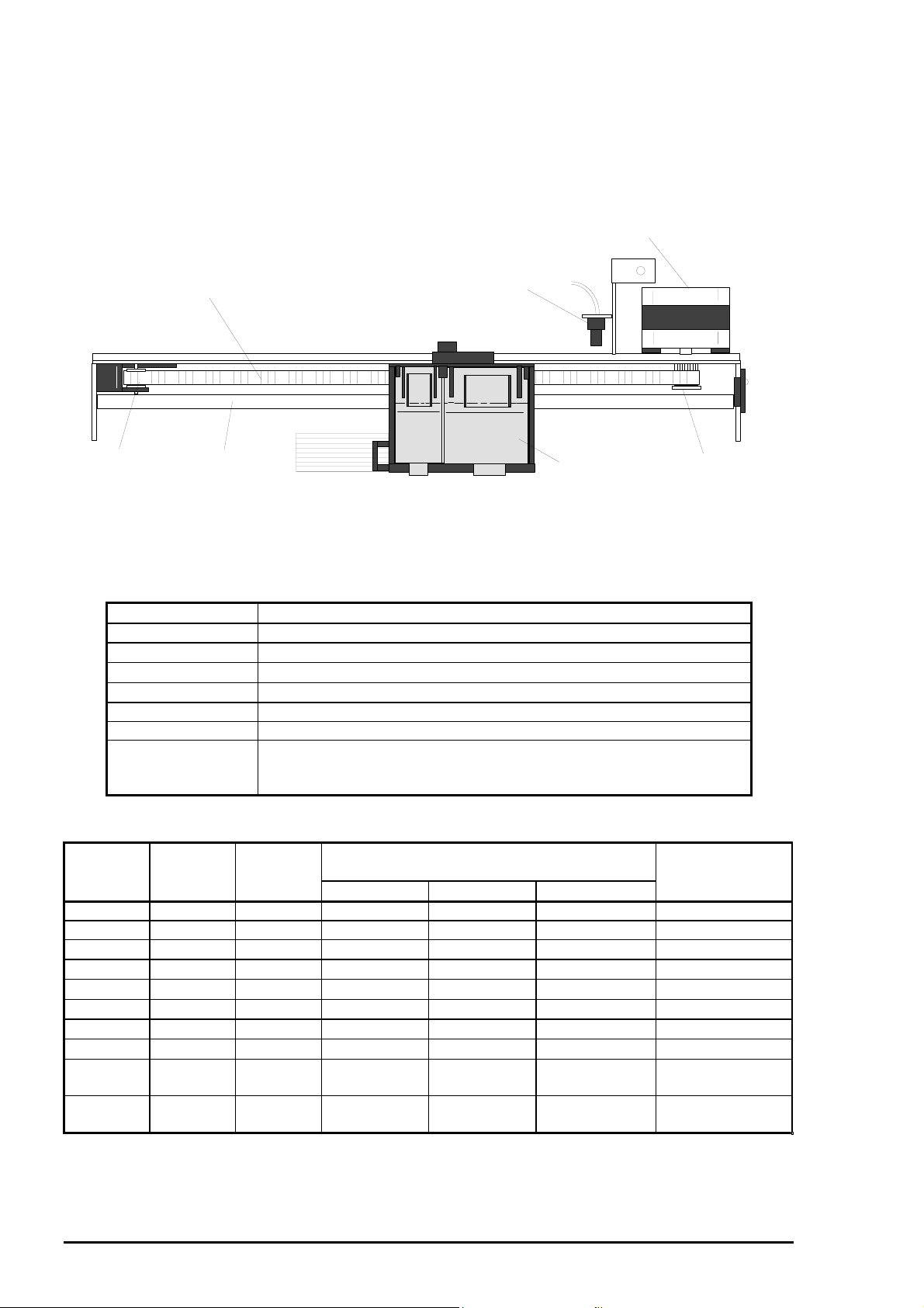
2.2.3 Carriage (CR) Mechanism
The CR mechanism is composed of the CR motor, Timing Belt, CR Guide Shaft, Top Frame, and Home
Position (HP) sensor. The torque from the CR motor is transmitted to the CR unit via the Timing Belt to
move the CR unit along the CR Guide Shaft both right and left, depending on the direction in which the CR
motor rotates. W hen the CR unit returns to the HP position, it is detected by the HP sensor mounted on
the right end of the Top Frame, and the information is fed back to the IC2 gate array (E05B33CB). Figure
2-4 illustrates the CR mechanism conception.
The CR motor, which drives the CR mechanism, is a 4-phases/200-pole/HB type stepping motor and is
CR Motor
HP Sensor
CR Unit
CR Motor Pinion Gear
Sub Pulley
Timing Belt
CR Guide Shaft
Figure 2-4. Carriage Mechanism
controlled by the constant current bipolar control system. The current control signal for eac h phase and
phase control signal output from the IC2 gate array E05B33CB are converted into the CR m otor control
signal by the IC13 bipolar driver UDN2917EB to control the CR motor. Refer to Table 2-2 and Table 2-3
which show the CR specification and the drive frequency.
Table 2-2. CR Motor Specification
Item Description
Motor type 4-phases / 200-pole / HB type stepping motor
Drive voltage
Coil resistance
Inductance
42 VDC ± 5%
7.8 Ω ± 10% (at 25° C per 1 phase)
14 mH ± 20% (1 KHz, 1 Vrms)
Drive frequency 240 ~ 4080 Hz
Excitation mode Bipolar drive
Minimum step 1/120 inch / pulse (2-2 phase drive), 1/240 inch / pulse (1-2 phase
drive)
1-480 inch / pulse (W1-2 phase drive)
Table 2-3. CR Motor Drive Terms
Mode CR speed
(CPS)
Drive
frequency
Drive system and acceleration/deceleration
step
Acceleration/
De celeration
(Hz) A*2:1, D*3:2 A:2, D:2 Constant pulse*
Fast skip 340 4080 64 (W1-2) 164 (2-2) (2-2) 180
DRAFT 266.7 3200 88 (W1-2) 86 (2-2) (2-2) 108
LQ 200 2400 432 (W1-2)
TEXT LQ 200 2400 240 (W1-2)
SLQ 100 1200 432 (W1-2)
Capping 90 1080 64 (W1-2)
wiping 2 80 960 64 (W1-2)
Wiping 40 480 16 (W1-2)
Capping
20 240 8 (W1-2)
(W1-2) 108
(W1-2) 60
(W1-2) 108
(W1-2) 16
(W1-2) 16
(W1-2) 4
(W1-2) 2
(open)
Constant
20 240
(W1-2)
value
Note) *1: Step : reduced to 2-2 phase
*2: Acceleration
*3: Deceleration
2-
1
Rev. A
Page 6
Operating Principles
5
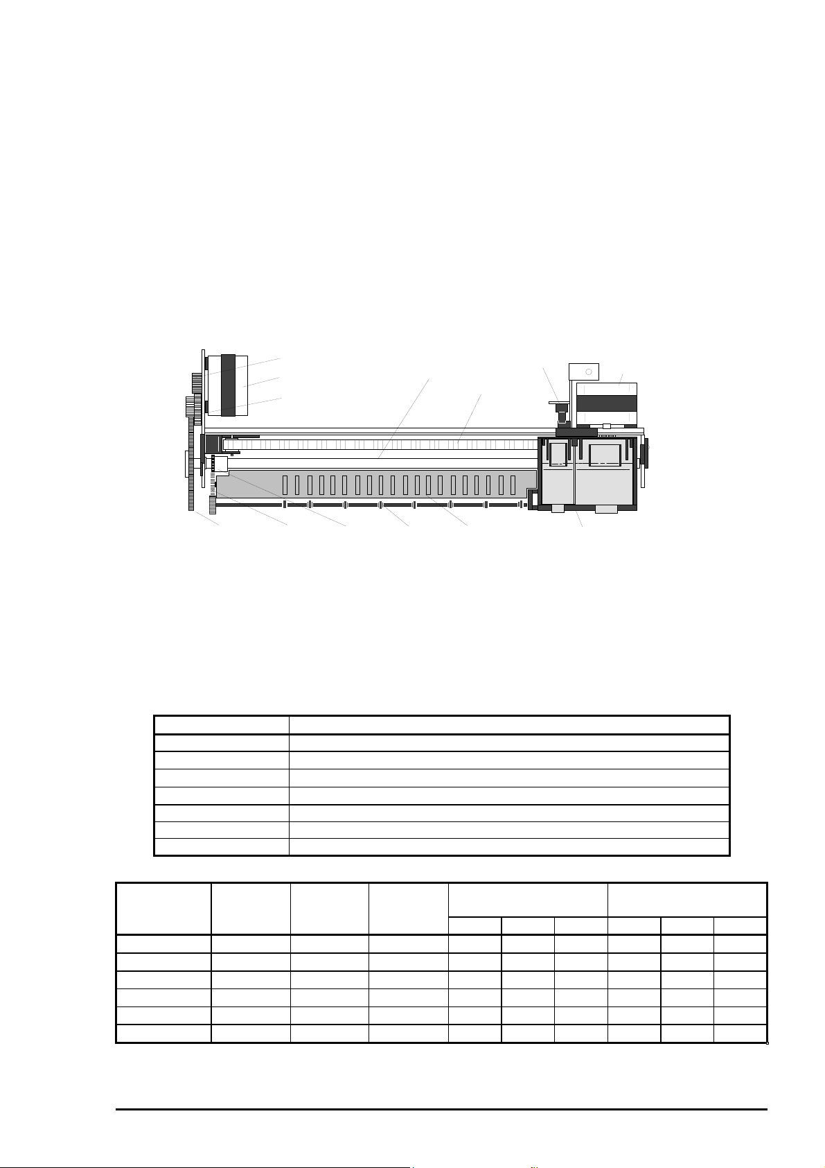
2.2.4 Paper Feed Mechanism
This printer is equipped with the PF motor which is used to feed paper only to improve f eeding s peed. The
drive from the Pump motor is used to load paper at the ASF and the drive from the PF roller is
independently used to feed paper only. The paper f eed mec hanism is classif ied to 2 parts; the paper f eed
part having the PF roller for the main assembly, and the paper eject part having the Paper eject roller for
the main assembly. The PF roller is coated with the powdery material, which is used to improve the paper
feed accuracy. The PF motor located at the rear left part of the printer mechanism tr ansmits the torque via
the Combination gear (14, 31.5) and Gear (70) to the PF roller assembly to feed paper loaded.
The torque is then transm itted from the Gear (17) on the Paper feed roller assem bly to the Paper eject
roller via the Gear (19) to eject paper. The torque is transmitted in the following order:
Paper feed part
1) PF motor pinion gear → 2) Combination gear 14, 31.5 → 3) Gear 70 → 4) PF roller assembly
Paper Eject part
1) PF motor pinion gear → 2) Combination gear 14, 31.5 → 3) Gear 70 → 4) Gear 17 (PF roller
assembly) → 5) Gear 19 (Front paper guide assembly ) → 6) Paper eject roller assembly (Front paper
eject assembly)
Gear 70
PF Motor Pinion Gear
PF Motor
Combination Gears 14, 31.5
Gear 19
Gear 17
Paper Eject
Roller
PF Roller Assembly
Paper Guide Assembly
(Front)
HP Sensor
Timing Belt
CR Motor
CR Unit
Figure 2-5. Paper Feed Mechanism
This printer uses a 4-phases/96-pole/HB type pulse motor which is controlled by the bipolar constant
voltage system for the PF motor. The current control signal for each phase and phase control signal
output from the IC2 gate array E05B33CB are converted into the PF motor control signal by the IC16
bipolar driver UDN2917EB to control the PF motor. Since the power switch of this printer is wired to the
secondary circuitry, the voltage remains the constant level until the loaded paper is ejected after the printer
power is turned off. Table 2-4 and Table 2-5 show the PF motor specification and PF motor drive
frequency, respectively.
Table 2-4. PF Motor Specification
Item Description
Motor type 4-phases / 96-pole / HB type pulse motor
Drive voltage
Coil resistance
Inductance
42 VDC ± 5% (The voltage applied to the driver)
7.8 Ω ± 10% (at 25° C per 1 phase)
14 mH ± 20% (1 KHz, 1 Vrms)
Drive frequency 400 ~ 4320 Hz
Excitation mode Bipolar drive
Minimum step 1/120 inch / pulse (2-2 phase drive)
Table 2-5. PF Motor Drive Terms
Mode
Feeding
speed-
Drive
Frequency
Pulse
interval-
Acceleration step
for each phase
Deceleration step
for each phase
(inch/s) (Hz) (us) W1-2 2-2 1-2 W1-2 2-2 1-2
Normal feed 5 3600 278
Fast feed 6 4320 231
Slow feed 2.5 1800 556
At loading 3 22160 463
Micro adjust 1 1.25 900 1111 2
Micro adjust 2 0.55 400 2500
50
60
20
30
2
50
60
20
30
Note) Drive frequency and pulse interval are reduced to 2-2 phase.
Rev. A
2-
Page 7
EPSON Stylus
6
&2/25
800
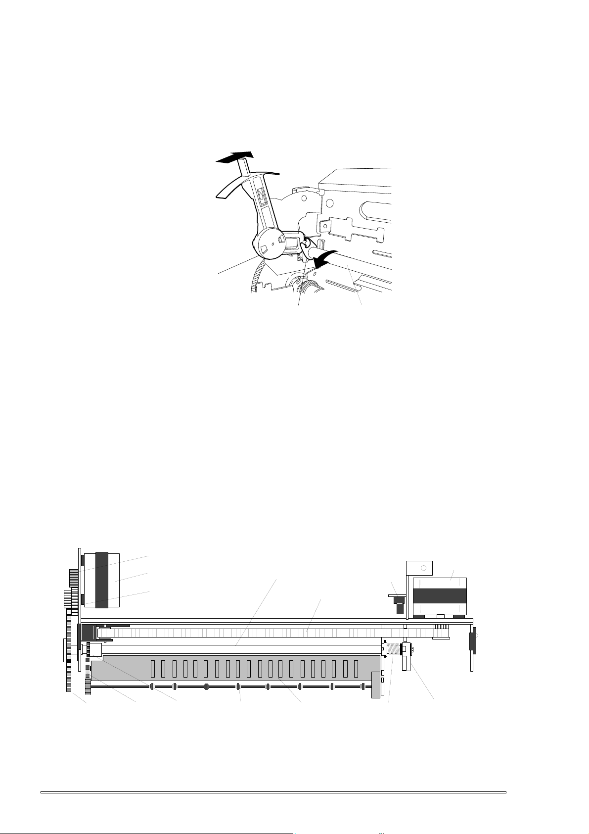
2.2.5 Platen Gap (PG) Adjust Mechanism
The PG adjust mec hanism, located at the lef t of the printer m echanism , consists of the PG lever, PF sub
lever, right/left parallelism adjust bushings, and CR guide shaft. PG adjust mechanism is equipped to keep
the proper platen gap according to the paper thickness to prevent ink from having friction. The PG lever
joins to the CR guide shaft which has an eccentr icity via PG sub lever, and switching the lever from “0” to
“+” rotates the CR shaft and the platen gap changes from narrow to wide. Figure 2-6 show the PG adjus t
mechanism .
PG Lever Position +
PG Lever Position 0
PG Lever
PG Sub Lever
CR Guide Shaft
Figure 2-6. PG Adjust Mechanism
2.2.6 CR Lock Mechanism
The CR lock lever, locate at the right side of the printer mechanis m, is composed of the PF motor, PF
roller assembly, Stopper lever (CR lock lever) and so on. When there is no paper loaded and no data
stored, CR lock m echanism fixes the CR unit to the c apping position. This operation is accom plished by
rotating the PF motor clock wise with the specified steps to set the stopper lever at the r ight end of the PF
roller to the left of the CR unit. The stopper lever is then r elease fr om the set position when the PF m otor
rotates counterclockwise with the specified steps. The drive from the PF motor is transmitted in the
following order;
1) PF motor pinion gear 2) Combination gear 14, 31.5 3) Gear 70
4) PF roller assembly 5) Stopper lever
The figure below shows the CR lock mechanism.
PF Motor Pinion Gear
PF Motor
Combination Gears
14, 31.5
PF Roller Assembly
Timing Belt
HP Sensor
CR Motor
Gear 70
Gear 19
Gear 17
Paper Eject
Roller
Paper Guide
(Front)
Compression Spring
5.85
Stopper Lever
Figure 2-7. CR Lock Mechanism
2-
Rev. A
Page 8
Operating Principles
7
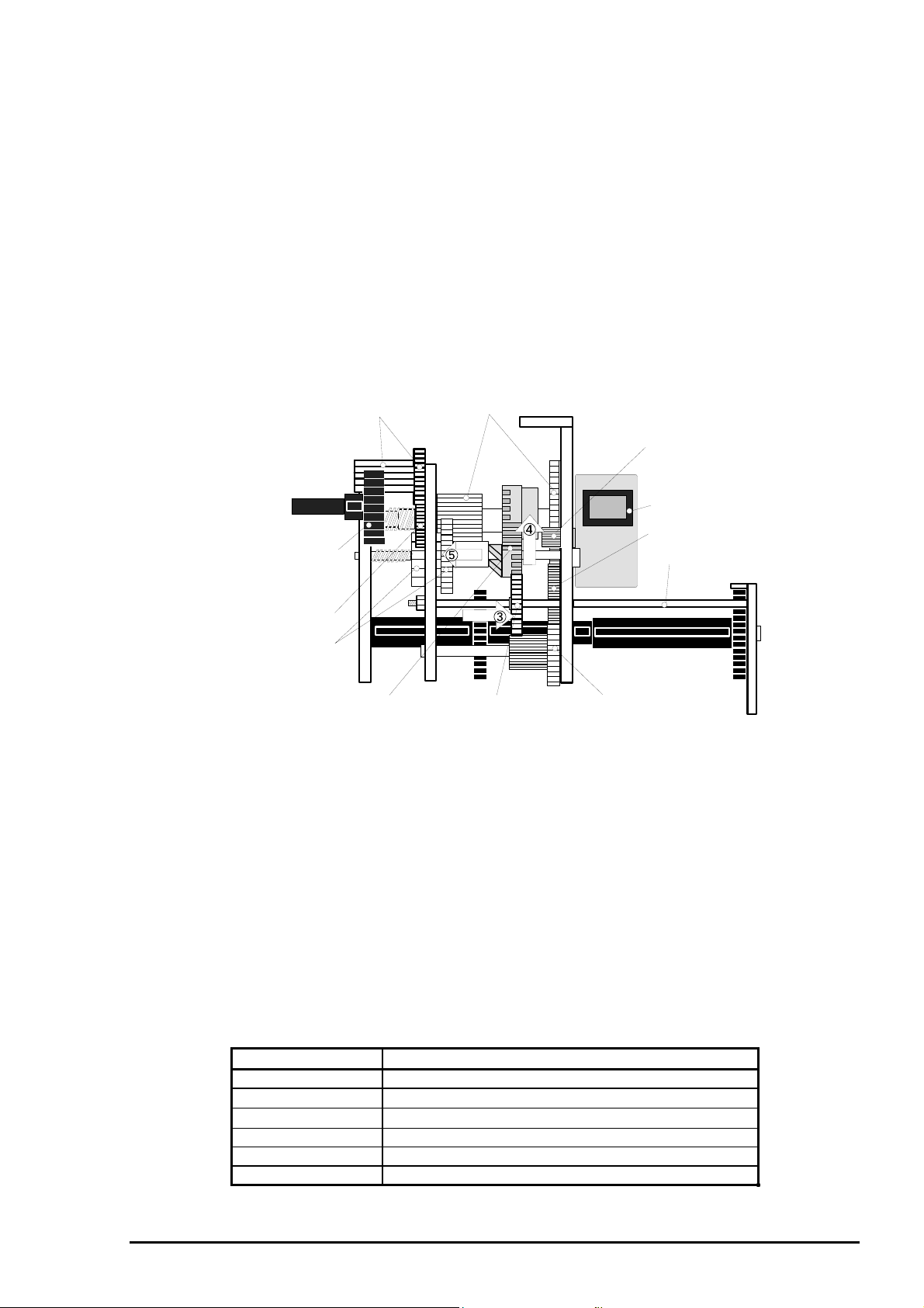
2.2.7 ASF Mechanism
ASF mechanism, which consists of the Pum p motor, slider mechanism , disengage mechanism , and ASF
unit, loads paper into the paper feed mechanism. When the CR unit returns to the home position, it
pushes the slider in the slider m echanism to the right and the Gear (16) in the slider m echanism then
comes to engage with the Change cam in the dis engage mechanism. W ith this m otion, the Pump m otor
rotates with the specified steps in the counter c lock wise, which switches the Change c am to the ASF unit
side, then the torque from the Pum p motor is transmitted to the ASF unit. The pr ocess in which the drive
from the pump unit is switched to the ASF unit side is described below. Figure 2-8 illustrates the process
for the switching operation.
Disengage mechanism switch process
1) CR shifts to the home position.
2) Slider shifts to the right end. (Slider mechanism)
3) The Gear (16) is engaged to the Change cam in the disengage mechanism. (Slider mechanism)
4) The Change Cam is switched to the ASF side. (Disengage mechanism)
5) The Combination Gear (14.4, 21.6) shifts to the left.
The figure below shows movement of above mentioned process 3) to 5).
Combination Gear
12, 20.8
Combination Gears
12, 26
Pump Motor
Pinion Gear
Pump Motor
Gear 11.5
Gear 27.2
Gear 16.8
Combination Gears
14.4, 21.6
Cam
Gear 16
(Slider Mechanism)
Combination Gears
12, 15
Slider Shaft
Figure 2-8. ASF Mechanism
Transmission process of the Pump motor’s torque
1) Pump motor pinion gear2) Combination gear 12, 26 3) Combination gear 14.4, 21.6
4) Gear 16.8 5) Combination gear 12, 20.8 6) Gear 27.2 (ASF unit)
7) LD roller shaft (ASF unit)
Note) This order has no relevance to the order in the figure above.
The ASF home position is sensed by the detection wheel attached to the right end of the LD roller shaft
and ASF HP sensor, and the detected condition is fed back to the IC2 E05B33CB. The ASF motor is
controlled based on the home position which is detected by the ASF HP sensor. A 4-phase/48 -pole PM
type pulse motor is used for the pump motor which is controlled by the constant current bipolar drive. T he
current control signal for each phase and phase control signal output from the IC2 gate array E05B33CB
are converted into the pump motor control s ignal by the IC6 bipolar driver UDN2917EB to control the PF
motor. Table 2-6 and Table 2-7 show the pump motor specification and pump motor drive frequency,
respectively.
Table 2-6. Pump Motor Specification
Item Description
Motor type 4-phases / 48-pole / PM type pulse motor
Drive voltage
Coil resistance
42 VDC ± 5% (The voltage applied to the driver)
9.3 Ω ± 10% (at 25° C per 1 phase)
Drive frequency 272 ~ 654 Hz
Excitation mode Bipolar drive
Minimum step 1/218 inch / pulse (2-2 phase drive)
Rev. A
2-
Page 9

EPSON Stylus
8
&2/25
800
Table 2-7. Pump Motor Drive Terms
Mode Frequency Pulse Feeding Acceleration step Deceleration step
interval speed W1-phase 1-2 phase W1-phase 1-2 phase
Paper back feed 436 2294 2 inch/S 5
5
ASF multiple feeding prevention mechanism
The paper loading assembly in the ASF is composed of the D-cut paper loading roller, C-cut cam,
paper feed back lever, and pinch roller. The C-cut cam and the D-cut roller have synchronous
movement staying on the same shaft. When they rotate counter clock wise (viewed from the right), the
paper feed back lever, moving in accordance with the notch portion of the C-cut cam, pushes the
dislocated paper back up to the standby position. Dislocation means the situation in which multiple
paper including the paper to be loaded at the next rotation slip off the standby position and fall into the
paper path.
D-Shape Paper
Loading Roller
Paper Feed Back Lever
C-Cut Cam
Pintch Roller
Hopper
Hopper Spring
Pad Spring
Figure 2-9. ASF multiple feeding prevention mechanism
ASF multiple feeding prevention mechanism operating principles
[Step1] : When the Load/ Eject switch is pressed or printing order is input from the PC, PF
motor rotates counterclockwise and makes the C-cut Cam rotates in the same
direction.
[Step2] : The Paper feed back lever clutched to the C-cut cam rises with the counter clock wise
rotation to catch the slipped paper. Along with this motion, the pad is pushed
backward and the Pinch roller and the D-cut paper loading roller become to no
friction condition.
[Step3] : When the dislocated paper is pushed back up to the standby position by the Paper
feed back lever, the counter wise rotation of the Pump motor releases the Release
hopper lever and the C-cut paper feed roller begins to load the paper.
[Step4] : When the ASF finishes to feed the paper to the specified position, the flat part of the
C-cut paper loading roller turns around to the paper path side, where the C-cut paper
loading roller loses contact with the paper and the Pinch roller supports the paper
instead. The paper Pinch roller continues to support the paper until the paper is
completely ejected from the ASF with the rotation of the PF roller. The Paper feed
back lever ,during this movement, is in the stand by position, as illustrated in the
above left figure.
2-
Rev. A
Page 10

Operating Principles
9
2.2.8 Ink System
The ink system for this printer is composed of the following and performs absorbing and ejecting ink,
cleaning the printhead surface, and capping the printheads.
Ink cartridge
Pump mechanism
Wiping mechanism
Capping mechanism
Waste ink drain pads
This section describes the operational principles of the pump mechanism and capping mechanism.
The figure below shows the structure of the ink system.
Pump
Motor
Combination Gear
12, 26
Combination Gear
14.4, 21.8
Cleaner Head
Black Ink Cartridge
Capping Mechanism
Color Ink Cartridge
Air Valve
Wiping Mechanism
Pump 1
Clutch
Pump Mechanism
Waste Ink Drain Pads
Pump Drive
Shaft
Gear 21.6
Pump 2
Pump Reduction
Shaft
Figure 2-10. Ink System
Rev. A
2-
Page 11

EPSON Stylus
0
&2/25
800
2.2.8.1 Pump Mechanism
The functions of the Pump m echanism, which is composed of the Pump motor, Slider mechanism, and
Disengage mechanism , are Absorbing black /color ink f rom the capping unit, f alse absorption, and setting
and resetting of the wiper. When the CR returns to the CR hom e pos ition, it pushes the s lider in the Slider
mechanism to the right end. That movement engages the Gear 16 in the slider mechanism with the
Change Cam in the Disengage mechanism. Then the Change Cam switches to the Pump mechanism
side when the Pump motor rotates c lock wise with the specified steps, and the drive from the Pump motor
is transmitted to the Pump mechanism. The torque is transmitted to the Pump side via the Disengage
mechanism in the following order:
1. Disengage mechanism switch process
2. CR shifts to the home position.
3. Slider shifts the right end. (Slider mechanism)
4. The Gear 16 is engaged to the Change Cam. (Slider mechanism)
5. The Change Cam switches to the pump side. (Disengage mechanism)
6. The Combination Gear 14.4, 21.6 shifts to the right. (Disengage mechanism)
The following figure shows how the gears are engaged.
Combination Gears
12, 20.8
Gear 27.2
Gear 16.8
Combination Gears
14.4, 21.6
Cam
Gear 16
(Slider Mechanism)
Combination Gears
12, 26
Pump Motor Pinion Gear
Pump Motor
Gear 11.5
Slider Shaft
Pump Drive Shaft
Combination Gears
12, 15
Pump Reduction Gear
Gear 21.6
Pump Unit
Figure 2-11. Pump Mechanism
Transmission process of the Pump motor’s torque
1) Pump motor pinion gear 2) Combination gear 12, 26 3) Combination gear 14.4, 21.6
4) Pump drive shaft 5) Gear 21.6 6) Pump reduction shaft
7) Pump unit
Note) This order is irrelevant to the order indicated with arrows in the figure above.
2-1
Rev. A
Page 12

Operating Principles
The pump unit switches its function depending on the direction in which the pump motor rotates, as show
in Table 2-8;
Table 2-8. Pump Motor Rotation and Function
Motor rotation direction Function
Clock wise direction
(Forward)
Counter clock wise direction
(Reverse)
Color ink absorption, Color ink false absorption,
Color ink Micro absorbing, Resetting the wiper
Black ink absorption, Black ink false absorption,
Black ink Micro absorbing, Setting the wiper
Note) The directions for the rotation are described when the motor is viewed from the pinion gear
side.
Pump Motor
(Clock Wise Direction)
Color Capping
Black Capping
Color Pump Side
Color Ink Absorbed
Color Capping
Color Pump Side
No Color Ink Absorbed
Waste Ink
Drain Pads
Waste Ink
Drain Pads
Black Pump Side Black Pump Side
No Black Ink Absorbed
Pump Motor
(Counter Clock Wise Direction)
Black Capping
Black Pump Side
Black Ink Absorbed
Wiper
Wiper Reset
Black Pump Side
Wiper Set
Figure 2-12. Pump Mechanism
The pump motor for this printer also drives the ASF m echanism. See Table 2-6 for its specification. The
drive terms for the pump motor in the pump mode is as shown in Table 2-9.
Table 2-9. Pump Motor Drive Terms in the Pump Mode
Absorption Mode Frequency Pulse
interval
W1-2
phase
High speed 1350 741
Normal speed 675 1481
Low speed 281 3559 0
At disengage 141 7092 0
Rev. A
Acceleration step Deceleration step
2-2
phase
30
1-2
phase
W1-2
phase
18
0
0
2-2
phase
30
1-2
phase
18
2-11
Page 13

EPSON Stylus
2
&2/25
800
2.2.8.2 Capping Mechanism
The capping mechanism caps the printheads with the cap holder to prevent the ink around the nozzles
from increasing viscosity while the printer is in stand-by status or the printer power is off. Is has 2 separ ate
holders; one for the color inks and the other for the black ink. W hen the CR shif ts fr om the hom e position
to the right end of the CR (Motion 1 in Figure 2-13), they move up into the c apping position (Motion 2 in
Figure 2-13) to cap the printheads. Moreover, by shifting the CR unit to the right end of the CR shaft, the
air valve is shut out completely (Motion 3 in Figure 2-13).
The air valve is released and shut to alternate the f alse absorption m ode and absorption m ode. (Ref er to
Section 2.4 for the details.) Since this printer has the Power supply board on the secondary electrical
circuit, capping operation is com pletely carried out with the constant voltage if the printer power is turned
off during the capping operation. The figure below shows the Capping mechanism.
To the Drain Pads
Black Ink Cartridge
Cap 1
Figure 2-13. Capping Mechanism
2
Cap 2
Color Ink Cartridge
2
2
1
3
Air Valve
Air Tubes
2-1
Rev. A
Page 14

Operating Principles
3
2.3 Electrical Circuit Operation Principles
This printer consists of the following circuit boards:
C202 MAIN board
C202 PSB/PSE board
C202 Panel board
In addition to the circuit boards above, the printhead driver circ uit is directly attached to each of the black
and color heads in the CR unit. This section describes the operational principle of the C202 PSB/PSE
board and C202 MAIN board. Table 2-10 shows the input voltages and applications.
Printer Mechanism
CR Motor
PF Motor
Pump Motor
Color Head
Driver Circuit
Sensors
Black Head
Driver Circuit
C202 PSB/PSE Board
+42 VDC
+5 VDC
C202 PNL Board
C202 MAIN Control Board
Figure 2-14. Electrical Circuit Block Diagram
2.3.1 C202 PSB/PSE board
The electrical circuit of this printer uses RCC (Riging Choke Converter) which outputs 2 different types of
the VDC necessary to operate the printer.
Table 2-10. DC Voltage Distribution
VDC Application
+42 V Motors
Printhead common voltage
+5 V C202 MAIN control board (logic)
C202 panel board
Sensors
(HP sensor, ASF HP sensor , PE sensor)
The power switch of this printer is in the secondary circuit that allows the PSB/PSE board to continue to
supply voltage for the power and logic lines for a minimum of 20 sec onds until the printhead r eturns to the
capping position even if the printer is turned off during printing. This extra tim e prevents ink leak age and
dried printhead caused by the printhead being left uncapped. The AC voltage from the AC inlet is first
input to the filter circuit for higher harmonics absorption and is then input to the rectification and smoothing
circuit, converting into DC voltage. This DC voltage is then input to the switching circuit. Along with this
switching operation by FET on the primary side, +42 voltage is generated and stabilized on the sec ondary
side, which is then converted into the stable +5 VDC by the chopping regulator IC.
Figure 2-15 shows the block diagram of the electrical circuit.
Rev. A
2-1
Page 15

EPSON Stylus
4
&2/25
800
Primary Circuit Secondary Circuit
Full Wave
Rectifier Circuit
Filter Circuit
AC Input
Smoothing
Circuit
Switching
Circuit
Photo
Coupler
Photo
Coupler
Smoothing
Circuit
+5V Switching Regulator
+5V Constant Voltage Control Circuit
+5V Over Current Protection Circuit
+42V Constant Current
Control Circuit
+5V Over Voltage
Protecion Circuit
+42V Over Voltage
Protection Circuit
+42V Over Current
Protection Circuit
Power Off Delay Circuit
+42V
+5V
Power Switch
Figure 2-15. VDC Circuit Block Diagram
The operating principles of various protection circuit and controller c irc uit in the f igure above ar e desc r ibed
below.
+5 VDC line over voltage protection circuit
The output voltage level of +5 V is monitored by a Zener diode (AD53) on the secondary circuit. If the
voltage level exceeds 9 V, the switching FET Q1 goes Off in the following order, and no induced
electromotive is generated and production of +5 VDC and +42 VDC stops as the result.
Zener diode (ZD53) detects voltage which exceeds +9 V at +5 V line.
Transistor Q81 goes On.
Photo coupler PC1 goes On.
FET Q31 goes On and the gate current for the switching FET Q1 is cut off.
Switching FET Q1 goes Off.
+5 VDC line constant voltage control circuit
Voltage at the +5 VDC line is monitored by the regulator IC51. Abnormal voltage at the +5 VDC line is
detected and the information is fed back to the +5 V conparator in the IC, then +5 VDC is controlled or
cut off.
+5 VDC line over voltage protection circuit
The output level of the +42 VDC line is monitored by the 2 Zener diodes ZD52 and ZD87. When the
output level of the +42 VDC line exceeds +48 V, the Switching FET Q1 goes Off in the following
sequence.
Zener diodes (ZD52, ZD87) detect the voltage over 48 V at the +42 V line.
Transistor Q81 goes On.
Photo coupler PC1 goes On.
FET Q31 goes On and the gate current for the switching FET Q1 is cut off.
Switching FET Q1 goes Off.
+42 VDC line constant voltage control circuit
Voltage at the +42 VDC line is monitored by the Zener diodes ZD51 and ZD81 to ZD86. When the
voltage at the +42 VDC line exceeds, the Switching FET Q1 is controlled in the following sequence.
Zener diodes (ZD52 and ZD81 to ZD86) detect the voltage over 38V at the +42 VDC line.
Transistor Q81 goes On.
Photo coupler PC1 goes On.
The transistors Q3 and Q2 go off and gate current for the switching FET Q1 is cut off.
Switching FET Q1 goes Off.
When the voltage level drops under +38 V, the photo coupler PC1 and transistors Q3 and
Q2 go Off and the swathing FET Q1 goes back On.
+42 VDC line overcurrent protection circuit
The output current is monitored by the transistors Q81 and Q82. When the output current is
abnormally low , the information is fed back to the primary circuit via the photo coupler PC1 to stop the
switching operation.
2-1
Rev. A
Page 16

Operating Principles
5
2.3.2 C202 MAIN Control Board
C202 MAIN control board consists of the following:
Logic circuits for PROM, DRAM, CPU, ASIC and EEPROM
Motor control and driver circuits for CR motor, PF motor, and pump motor
Head control/ driver circuit for the black and color heads
Other circuits for the I/F (Parallel I/F, Mac serial. Type B I/F), sensors, RTC timers, and reset
Figure 2-16 shows the circuit block diagram for the main control board.
C202 MAIN Control Board
C202 PNL Board
IC3
P-ROM (4M)
IC1
CPU
IC7
CG-ROM
(16M)
Ink Cartridge
(Black)
Black Ink
Driver Circuit
Ink Cartridge
(Color)
Color Head
Driver Circuit
IC5
DRAM (4M)
Common
Driver
Common
Driver
IC2
Gate Array
C202 PSB/PSE
Board
+42 V
+5 V
IC11
EEPROM
IC20
Timer IC
IC16
PF Motor
Driver
IC13
CR Motor
Driver
IC6
Pump Motor
Driver
IC15
Mac Serial I/F
Tranceiver IC
IC9
5V line
Reset IC
IC8
+42V line
Reset IC
Data Bus
CR Unit
Address Bus
HP
Sensor
PE
Sensor
Figure 2-16. C202 MAIN Board Block Diagram
Table 2-11 shows the allocated functions for the CPU and the gate array.
Table 2-11. Allocated Functions for the CPU and the Gate Array
IC Location Function
Sets the current value for each motor.
Outputs the driving trigger pulse for each motor.
Outputs the driving trigger pulse for each head
Outputs the system clock.
CPU IC1
Inputs the resistance value for the thermistor .
Inputs the On/Off signal of installation status for
each cartridge.
Transfers received data from I/F to DRAM
Controls interruption signals
Controls the motor drivers.
Controls printing data for each head.
Controls data from I/F and transfers it to the CPU.
Gate Array IC2
Outputs head driver control pulses.
Counts dot numbers used for printing.
Controls voltages for EEPROM, control panel,
timers, and heads.
HP
Sensor
IC12
Parallel I/F IC
Type B I/F
Rev. A
2-1
Page 17

EPSON Stylus
&2/25
800
2.3.2.1 Printhead Driver Circuit
The printhead driver circuits, which are separately built in for the blac k and color heads, consist of the
common drivers (black head:IC17, color head:IC18) on the C202 MAIN board and nozzle selec tors ( Black
head:IR2C72C, Color head: IR2C73C) on the head driver boards. Each common driver produces
trapezoidal pulses according to the signals sent fr om the IC2 gate array, and transfer them to the nozzle
selector on the head driver board. Printing data is converted into serial data at the gate ar ray and is then
transferred to the nozzle selector on the head driver board to select the nozzles to be activated. The PZT
common lines are selectively driven simultaneously based on the driver waveform produced at the
common driver to activate the nozzles selected by the printing data.
+42V
C202 MAIN Board
+5V
Black Printhead Driver Board
Gate Array
IC 2
E05B33CB
BCHG 68
BKC 61
BND1 67
BND2 66
BMD1 63
BMD2 62
SBDATA 75
SCLK 79
BHCLK 87
BHLAT 86
BBHDATA 89
BAHDATA 90
VHPR 82
CCHG 74
CKC 69
CND1 73
CND2 72
CMD1 71
CMD2 70
SCDATA 76
CHCLK 95
CHLAT 94
YHDATA 99
MHDATA 98
CHDATA 97
IC 17
HBD2813C
Common Driver
(Black Head)
IC 17
HBD2813C
Common Driver
(Color Head)
CN9
CN10
Common
Signal
Common
Signal
VDD
CCLK
CLAT
VH
CSI2
IR2C72C
Nozzle
Selector
VDD (+5V)
BCLK
BLAT
BSI2
BSI1
VH
IR2C72C
Nozzle
Selector
VDD (+5V)
CCLK
CLAT
CSI3
CSI1
VH
IR2C73C
Nozzle
Selector
Black Head
Drive Waveform
Color Head
Drive Waveform
Color Printhead Driver Board
Figure 2-17. Printhead Driver Circuit Block Diagram
Common driver circuit for the black head
The common driver IC17 HBD2813C produces trapezoidal waveforms by combining the 6 different
signals BCHG, BND1, BND2, BMD1, BMD2 and BKC output from the IC2 E05B33CB gate array using
VM voltage as the basis. There are 7 particular types of trapezoidal waveforms produced for the
normal dot mode, Micro dot mode and so on, and each form varies depending on the width of the
combined signals. The rising form is determined by the BCHG and BKC regardless of the printing
mode. The falling form is determined by the 2 different pairs of signals; BND1 and BND2 in the normal
dot mode, and by BMD1 and BMD2 in the micro dot mode. The VH voltage adjusting values stored in
the EEPROM, which is unique to each head and, is read into the gate array, and then transferred in 8bit serial data via CBDATA signal to be set in the common driver. With this procedure, the internal
resistance is determined and the driver waveform is adjusted as the result.
2-16
Head Drive Waveform
LAT
NCHG
BCHG
BND1
BND2
BMD1
BMD2
BKC
Figure 2-18. Waveform Producing Process for Black Nozzle
Rev. A
Page 18

Operating Principles
7
Black head nozzle selector circuit
The printing data is input from the data input ports D0 to D15 of the IC2 E05B33CB gate array to the
gate array to be converted into serial data and output to the nozzle selector from the BBHDATA and
BHADATA ports. The data is then separated to 2 sides through the port BBHDATA and BHADATA
which are allocated with 2 lines of black nozzles; the lines #1, #3 and #2, #4 respectively. The smallernumbered nozzle on each line receives data faster. Data is transferred from IC2 gate array to Nozzle
selector IC IR 2C72C at 64 bit / 2.5 MHz synchronizing with the BHCLK (Clock signal) and BHLAT
(latch signal). On/Off status of each nozzle in the nozzle selector is determined based on the data
transferred.
Common driver circuit for the color head
The circuit structure for the color head is basically the same as for the black head. The common driver
IC18 HBD2813C produces trapezoidal waveforms by combining the 6 different signals CCHG, CND1,
CND2, CMD1, CMD2 and CKC output from the IC2 E05B33CB gate array. There are 7 particular
types of trapezoidal waveforms produced for normal dot mode, Micro dot mode and so on, and each
form varies depending on the width of the combined signals. The rising form is determined by the
CCHG and CKC regardless of the printing mode. The falling form is determined by the 2 different pairs
of signals; CND1 and CND2 in the normal dot mode, and CMD1 and CMD2 in micro dot mode. The
VH voltage adjusting value stored in the EEPROM, which is unique to each head is read into the gate
array, and then transferred in 8-bit serial data via SBDATA signal to be set in the common driver. With
this procedure, the internal resistance is determined and the driver waveform is adjusted as the result.
Head Drive Waveform
LAT
NCHG
CCHG
CND1
CND2
CMD1
CMD2
CKC
Figure 2-19 Waveform Producing Process for Color Nozzles
Color head nozzle selector circuit
The printing data is input from the data input port D0 to D15 of the IC2 E05B33CB gate array to the
gate array to be converted into serial data, and output to the nozzle selector from the YHDATA,
MHDATA , and CHDATA ports according to the color. The data is then allocated to the corresponding
nozzle lines, alternating 2 lines; from #1 to #2. Data is transferred from IC2 gate array to Nozzle
selector IC IR 2C72C at 64 bit / 2.5 MHz synchronizing with the BHCLK (Clock signal) and CHLAT
(latch signal). On/Off status of each nozzle in the nozzle selector is determined based on the data
transferred.
Rev. A
2-1
Page 19

EPSON Stylus
8
&2/25
800
2.3.2.2 Reset Circuits
The C202 MAIN board contains two reset circuits; for logic line (+5 V) and power line (+42 V). The
voltages for +5 V and +42 V in each reset circuit are monitored to prevent printer m alfunction caused by
abnormal voltage levels. W hen an abnormal condition is detected, a reset signal is sent to the CPU to
reset the CPU and the gate array. The function of the reset circuit is described below.
Reset circuit for the +5 V line
The +5 V reset circuit monitors voltage level for the +5 V line at the port 3 VCC of IC9 PST592D, and
outputs a reset signal from the port 1 VOUT to the CPU gate array when it detects an abnormal
voltage level. The IC9 is energized under the conditions below.
When the printer is turned On, a reset signal is output for 100ms after the +5 V line voltage level
rises to 4.2 V.
During printing operation, when the 5 V line voltage level drops under 4.2 V, a reset signal is output.
The reset signal does not go off until 100 ms passed after the +5 V line voltage level recovers to 4.2
V, as described above.
Reset IC for +5V line
IC1
CPU
RES
IC9
81
VOUT 1
MRES 2
VCC 3
GND 4
+5V
R29 1K
27 MRES
23 RESET
+5V
IC2
Gate array
Figure 2-20. Reset Circuit for the +5 VDC line
Reset circuit for the +42 V line
The +42 V reset circuit monitors voltage level of 42 V at the port 3 VCC of IC8 M51955D, and feeds
back the information on the Power On/Off status to the CPU according to the detected voltage. When
the +42 V line drops under +33.2 V, IC8 detects the Power Off status and outputs an reset signal from
the port 6 to the CPU port 82 NMI via OR circuit of the IC19. When the voltage level recovers to 32.2
V, the port 6 of the IC8 stops outputting the signal, which is detected at the port 78 of the CPU.
NC8 8
VCC 7
OUT 6
NC5 5
+5V
IC19
1
4
2
TC7S32F
R78
10K
82 NMI
78 P21
IC1
CPU
27 MRES
IC2
81RES
23 RESET
Gate Array
LED4
113
R11
120K
1%
R12
4.65K
1%
+42V
C15
0.1U
Reset IC for +42V line
1 NC1
2 IN
IC8
3 NC3
4 GND
+5V
Figure 2-21 Reset Circuit for the +42 VDC line
2-1
Rev. A
Page 20

Operating Principles
9
2.3.2.3 Motor Driver Circuits
This printer is equipped with the 3 motors ; CR motor, PF motor, and pump motor. Since they are all driven
by the UDN2917EB, they use the same control system.
CR motor driver circuit
The phase control signal for the CR motor is converted into the UDN2917EB Micro-step bipolar driver
system at the IC2 gate array, then output from the port 55 to the port 43 and 26 of the IC13
UDN2917EB. IC13 determines the phase mode according to the signal sent. The current control
signal is also produced in IC2 gate array and output from the port from 51 to 54 to the port 1, 2, 23 and
24 of the IC13 UDN2917EB.
PF motor driver circuit
The motor driver circuit for the PF motor is the same as for the CR motor.
Pump motor driver circuit
The motor driver circuit for the Pump motor is the same as for the CR motor.
198
CRTRG
IC2
Gate Array
Data Bus
IC1
CPU
CRA0
CRA1
CRB0
CRB1
CRAPH
CRBPH
DA1
51
52
53
54
55
56
112
2
I10
1
I11
23
I20
24
I21
43
PH1
26
PH2
UDN2917EB
44
VREF1
25
VREF2
IC13
Figure 2-22. CR Motor Driver Circuit
6
A
3
A
18
B
21
B
1 CR A
3 CR-A
2 CR B
4 CR-B
CR Motor
Rev. A
2-1
Page 21

EPSON Stylus
0
&2/25
800
2.3.2.4 Sensor Circuits
The sensors equipped with this printer are as follows:
3 photo diode sensors :HP sensor, ASF HP sensor, PE sensor
2 mechanism switch sensors :Black and White cartridge sensors
1 thermistor for the color head
HP sensor
HP sensor, which is mounted to the upper right end of the top frame, determines the CR home
position. When the CR returns to the home position, the detector plate attached to the back of the CR
unit cuts in between the sensor terminals, and a High signal is output to the CPU. Low signal is then
output to the CPU when the CR leaves the home position.
ASF HP Sensor
This sensor is mounted to the left end of the ASF to detect the ASF home position. While the printer is
in standby status after the printer power is on, the ASF is controlled to be located in the ASF home
position, which means the ASF is ready to load paper. ASF HP position is detected by the ASF HP
sensor and the ASF detector wheel attached to the left end of the LD roller. The ASF HP detector
wheel has a small portion cutout and when the cutout comes into the position between the photo diode
terminals, the ASF home position is detected. Under this condition, Low signal is output to the CPU.
Therefore when the cutout goes out of the home position, the ASF detector wheel cuts in between the
photo diode terminals and High signal is output.
PE sensor
PE sensor, which is mounted onto the bottom right end of the Top frame in the printer mechanism,
detects paper end condition. The paper end condition is detected when the detector plate on the PE
sensor lever cuts in between the photo diode terminals and a High signal is output to the CPU. When
the paper was loaded, it pushes up the PE sensor lever. With this motion, the detector plate, along
with the PE sensor lever, is upheld so that it does not fall in between the diode terminals, and a High
signal is output to the CPU.
Ink cartridge sensor
Ink cartridge sensor which is built into each printhead determines if the black/color ink cartridge is
installed. If the cartridge is installed, the sensor plate is pressed down and it connects 2 terminals on
the printhead driver board, and then Low signal is output to the CPU. With no cartridge installed, the
sensor plate loses contact with the terminals on the printhead driver board, and High signal is output to
the CPU.
Printhead thermistor
Printhead thermistors are directly attached to each black and color printhead driver board. This printer,
however, only refers to the signal from the thermistor on the color head. The thermistor monitors the
temperatures around the printhead and feeds back the information to the analog port 105 of the CPU.
This information allows the printer to control the discharge voltage of the head drive pulse according
the ink viscosity.
+5V
Head Thermistor
Black Ink Cartridge
Sensor
Color Ink Cartridge
Sensor
105
106
107
AN0
P41
P42
IC1
CPU
Data Bus
IC2
Gate Array
SWA0
SWC0
SWC1
59
60
57
+5V
+5V
+5V
HP Sensor
+5V
ASF HP Sensor
+5V
PE Sensor
Figure 2-23. Sensor Circuit
2-2
Rev. A
Page 22

Operating Principles
2.4 Ink System Management
This section explains how the ink system is controlled to protect the printheads and the ink supply system
to ensure high-quality output. This printer has several ink system control sequences which var y depending
on the combinations of the basic ink system operations. T he pr inter s elec ts the most suitable sequence by
referring to the various printer information such as values for the timers and counters stored in the
EEPROM, flag and numbers of sensor signals. This section describes the basic ink operations, timers
counters and ink sequences.
2.4.1 Ink System Operations
The basic ink system operations are as described below.
Rubbing
This operation is to rub the printhead surface against the felt part of the head cleaner (left half of the
blade) in the pump unit by shifting the CR from left to right. The printer operates this to eliminate ink
and dust adhered to the printhead surface to regain normal ink ejection state and ensure firm capping
operation. A little amount of ink is absorbed to the nozzle surface before Rubbing operation to let the
adhered objects come off easily.
Wiping
During this operation, the CR moves from right to left to rub the printheads against the rubber part of
the head cleaner (right half of the blade) in the pump unit. The printer performs this operation prior to
ink absorption by eliminating the ink and dust adhered on the printheads to regain normal ink ejection
state and ensure firm capping operation.
Ink Absorbing operation
This operation is to absorb ink from the ink cavities by rotating the pump for the both black and color
heads with the specified steps while the head surfaces are capped and the air valve is closed. The
printer performs this operation to eliminate the ink which has increased viscosity and bubbles around
the nozzles.
False Absorbing operation
This operation removes ink remaining inside the caps by rotating the black and color pumps with the
specified steps while the head surfaces are capped and the air valve is opened. This operation is
accomplished to remove ink from the nozzle plate by vacuuming and ejecting the ink remained after
the Ink absorbing operation and Flushing operations.
Micro Absorbing
This operation absorbs ink from the ink cavity by rotating the black and color pumps with the specified
steps while the head surfaces are capped and the air valve is opened. The purpose of this sensitive
operation is to eliminate bubbles formed in the ink cavities during the Ink absorbing operation.
Flushing operation
This operation is to eject the specified amount of ink from the head when the CR goes into the false
absorbing position. This is performed to avoid increase in ink viscosity. There are 3 types of Flushing
operations, as listed below;
Table 2-12. Flushing Specification
Numbers of shots Driver waveform
Power flushing 4000 shots + 2V, Maximum 36V f or the correc t voltage of the
normal dot
Periodical flushing 36 shots Waveform for the normal dot
Cleaning flushing 1400 shots Waveform for the normal dot
Micro Vibration
Micro Vibration is performed to prevent ink from increasing viscosity. It adds the micro vibration to the
ink inside the cavity by applying driver voltage and pulse which vibrate the piezo elements. The printer
only performs this operation while the CR motor is accelerating to move the CR for printing operation.
Rev. A
2-21
Page 23

EPSON Stylus
2
&2/25
800
2.4.2 Timers and Counters
This printer is equipped with numbers of timer counters, s oft counters and flag. Their values, which are
mostly stored in the EEPROM, are the basis for selecting the ink sequence to be performed.
CL Timer
CL Timer manages auto cleaning. It remains active while the printer power is off and is reset when the
cleaning sequence is executed.
Accumulated Printing Timer
This timer accumulates the period of time spent for printing. The value of this timer is not cleared after
the printer is powered off. This timer is activated when the cap is removed and pauses the job when
the printer goes into the waiting status. The value of this counter is reset when the Ink Absorbing
operation is executed.
Power Off Timer
This timer monitors how long the printer power is off.
Ink Counter RB, Ry
This counter monitors the amount of ink used in the cap during the Flushing operation. The value is
stored after the printer power is turned off. When the value exceeds the specified value, the printer
performs the False Absorbing operation and then resets the counter.
CL2 Counter KKb, Kky
The printer uses the value on this counter for the basis of determining the manual cleaning sequence
order operated thorough the control panel. A cleaning is usually performed in the order of CL1, CL1’,
and CL2. This printer, however, doesn’t necessarily follow this order depending on the numbers of
pages printed after the latest cleaning sequence was performed.
(Set individually for the black and color inks.)
(Set individually for the black and color inks.)
(Set individually for the black and color inks.)
(Set individually for the black and color inks.)
Protect Counter A
This counter monitors the total amount of ink drained into the wast ink drain pads. When the value
exceeds the specified value (counter value:49000), the maintenance error occurs. This counter is
reset by performing the EEPROM reset operation.
Ink Consumption Counter Cb, Cy, Cm, Cc
(Set individually for the black and color inks.)
Each counter counts the amount of ink consumed thorough out the printing, cleaning, and Flushing
operations after the ink cartridge is installed. The printer or the EPW indicates the Ink low and Ink end
status according to the value on this counter. Even though the printer is turned off before a cleaning
sequence compoletes, the printer regards the job as a full cleaning and adds the specified value of the
cleaning to the consumption counter. This counter is reset when the cartridge is removed only in the
Cartridge replacement operation mode which is selected by the Panel Operation.
Table 2-13. Ink Consumption Counter
Black ink cartridge Color ink cartridge
Ink low counter
Ink end counter
37.6×10
41.6×10
7
7
17.2×10
19.2×10
7
7
2-2
Rev. A
Page 24

Operating Principles
3
2.4.3 Ink System Sequence
The ink system sequences operated in this printer are combinations of the basic ink system operations
described in Section 2.4.1. The printer selects the most suitable ink sequence according to the information
provided by the various counters, timers, and flags . T he major ink system sequences are des c ribed in this
section.
Manual Cleaning
Manual cleaning is performed by pressing the cleaning button on the control panel. The cleaning
mode is to be used is selected from following 5 modes according to the CL2 Counter value for KKB,
Kky (cleaning selecting counter) and number of the pages printed after the latest cleaning.
CL1 (Normal cleaning mode) : Wiping, Ink Absorbing, Micro Absorbing, False Absorbing.
CL1’(Powerful cleaning mode) : Wiping, Ink Absorbing, Micro Absorbing, False Absorbing.
The composed operations are same as for CL1, except the
amount of consumed ink.
CL2 (Powerful cleaning mode) : Wiping, Rubbing Ink Absorbing, Micro Absorbing,
False Absorbing.
Every operation except for Rubbing is the same as for CL1’.
However, the amount of the consumed ink is larger than CL1’
CL3 (False cleaning mode) : Wiping, Micro Absorbing, False Absorbing.
The amount of consumed Ink is very little since Ink Absorbing
is not operated.
One time CL : Wiping, Ink Absorbing, Micro Absorbing, False Absorbing.
The composed operations are same as for CL1, except the
amount of consumed ink. This cleaning mode consumes the
largest amount of ink.
CL2 counter is used to determine the cleaning mode to be performed when the forcible cleaning is
repeated. The counter is reset if the printer is turned off. The printer normally follows the order
CL1 → CL1’→ CL2, which, however, can vary depending on the conditions, as described below;
CL3 is selected if no image is printed after the latest cleaning.
CL1 is selected if 5 pages or less is printed after the latest cleaning.
CL1, CL1’ or CL2 is selected according to the CL2 Counter value for Kkb, Kky under the
following conditions;
5 pages or more is printed after the latest cleaning, and the current ink cartridge is a
replacement of the old one which was removed according to the Ink End-Low error
indication.
One time CL is performed under the following condition;
5 pages or more are printed after the latest cleaning, and the current cartridge is a
replacement of the old one which was removed without the Ink End-Low error indication.
Timer Cleaning
This cleaning is performed automatically based on the value for the CL Timer counter while the printer
power is On. This sequence, having 4 separate modes (Timer CL1, Timer CL2, Timer CL3, and Timer
CL4) for each black and color ink, differs from the manual cleaning modes in the basic ink system
operation sequence. It doesn’t contain Ink Absorbing but Wiping and Micro Absorbing operations.
Therefore the consumed ink amount is a little compared with the manual cleaning.
Power ON Sequence
During this sequence, the printer performs the following:
Refers to Protect Counter A.
Resets CL2 Counter Kkb, Kky.
Checks if the ink cartridges are installed.
Checks consumed ink amount.
Performs necessary cleaning based on the conditions such as Initial charging, HP status,
Power Off Timer, and CL timers.
Resets Power off timer.
Rev. A
2-2
Page 25

EPSON Stylus
4
Cartridge Replacement Sequence
The printer determines which ink cartridge (black or color) needs replacing in Cartridge replacement
CL sequence according to the conditions such as cartridge installation, Ink Low and Ink End. Cartridge
replacement CL sequence consists of Wiping, Ink Absorbing, Micro Absorbing, and False Absorbing,
and consumes less ink than that of the manual cleaning sequence. If the Initial charge flag is not
detected during this operation since the printer is new, the printer enters Initial ink charge sequence
instead. During Cartridge replacement sequence, One-time flag is reset or set in the EEPROM
according to the consumed ink amount for the removed cartridge (If 50% was used or not.). This flag
indicates whether the cartridge was removed because of the Ink End status or by accident. The printer
stores this information in the EEPROM to refer when selecting the manual cleaning mode to be
carried out. In case that the ink cartridge was removed from the CR unit with the condition that less
than 50% ink was consumed, the one-time flag is set in the EEPROM and one-time cleaning is carried
out at the first manual cleaning operation after completion of Cartridge replacement Sequence.
Initial Charge Sequence
The printer performs Wiping, Rubbing, Ink absorbing, Micro absorbing, and False absorbing during
Initial charge sequence. This sequence is performed according to the Initial charge flag status. This
sequence, which consumes a large amount of ink (about 20 % of total ink amount), requires
approximately 7 minutes to execute, and CL timers for each color, Accumulated printing timer, Initial
ink charge flag, and One-time flag are reset with the completion of this sequence.
&2/25
800
2-2
Rev. A
 Loading...