

Page 1

Chapter 5
Troubleshooting
5.1. General Description ............................................................................................5-1
5.2. Troubleshooting Information..............................................................................5-1
5.2.1. Error mode ............................................................................................................................. 5-1
5.2.2. Sensor Check Points.............................................................................................................5-2
5.2.3. Motor Check Points............................................................................................................... 5-2
5.3. Repair and Replacement of the Unit Part..........................................................5-3
5.4. Repair of the C202 PSB/PSE Board Component ............................................5-11
5.5. Repair of the C202 MAIN Board Component...................................................5-13
5.6. Repair of the Printer Mechanism......................................................................5-16
Page 2
Troubleshooting
5.1 General Description
This section describes how to identify and troubleshoot the problems when repairing the printer by dividing
the troubles into two levels; repair and replacement of the assemblies and units, and repair of the
components. W hen replacing or repairing the unit or assem bly, be sure to refer to the cor responding flow
chart which enables you to isolate the defective assembly or unit easily according to the symptom
occurred. In repairing the component, refer to Section 5.4 and 5.5 which provide check points listed
separately according to the major electric parts.
5.2 Troubleshooting Information
This section provides inf ormation on the er ror modes displayed on the control panel and check lis ts used
to determine if the units in each assembly are normally functioning.
5.2.1 Error mode
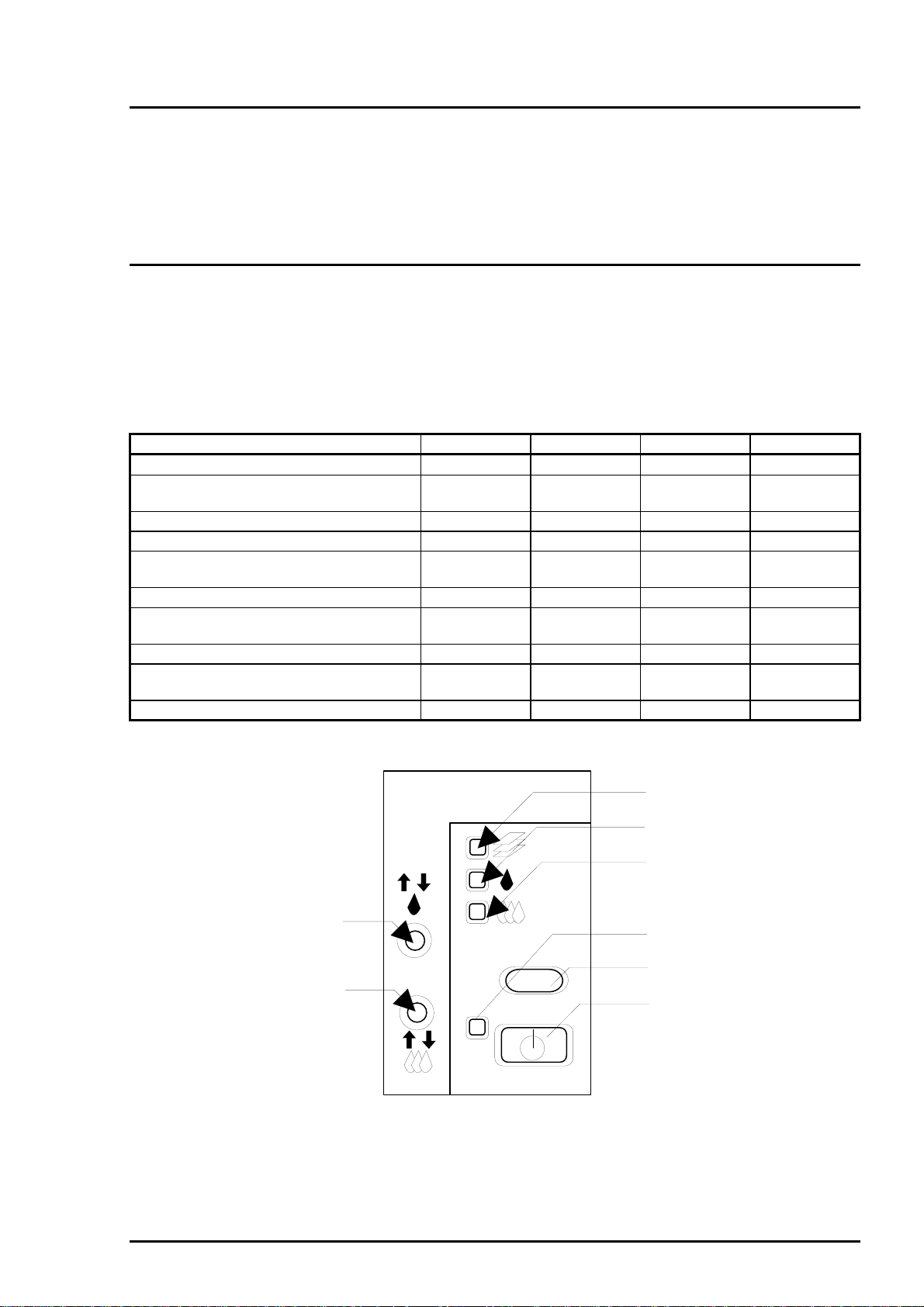
The LEDs on the control panel indicate several abnorm al status of this printer. Table 5-1 lists the printer
errors and corresponding LED status. (Refer to Figure 5-1 for LED arrangement.)
Table 5-1. Printer Error Status
Printer status LED (a) LED (b) LED (c) LED (d)
Ink sequence is proceeding. Blinks
Ink cartridge change sequence is
proceeding.
Paper out
Paper jam
Black ink cartridge ink end
No black ink cartridge installed
Black ink cartridge ink low
Color ink cartridge ink end
No color ink cartridge installed
Color ink cartridge ink low
Maintenance required (Waste ink pad
needs replacing.)
Fatal error Blinks Blinks On On
Note) “−−−” means no effect.
Blinks
−−−
−−−
−−− −−−
−−− −−−
−−− −−− −−−
−−− −−− −−−
Blinks Blinks Blinks Blinks
−−− −−− −−−
−−− −−− −−−
On
Blinks
−−− −−−
−−− −−−
On
Blinks
Blinks
−−−
−−−
On
(3)
(4)
(b)
(c)
(d)
(a)
(2)
(1)
Figure 5-1. Control Panel
Rev. A
5-1
Page 3
EPSON Stylus
&2/25
800
5.2.2 Sensor Check Points
Table 5-2 shows the check points for each sensor.
Table 5-2. Check Points for Each Sensor
Sensor Connector
No.
CN6 (HP sensor) 1:HP
CN7
(ASF HP sensor)
CN8 (PE sensor) 1:PE
CN9
(Black cartridge
detecting sensor)
CN10
(Color cartridge
detecting sensor)
Test pin No Test procedure
(Meter is set to the DC voltage.)
Set the “+” lead of the meter to the
2:GND
3:HPV
1:ASF
2:GND
3:ASFV
2:GND
3:PEV
1:BCO
3:GND
1:CCO
3:GND
pin 1 and “-” lead of the meter to
the pin 2.
Set the “+” lead of the meter to the
pin 1 and “-” lead of the meter to
the pin 2.
Set the “+” lead of the meter to the
pin 1 and “-” lead of the meter to
the pin 2.
Set the “+” lead of the meter to the
pin 1 and “-” lead of the meter to
the pin 3.
Set the “+” lead of the meter to the
pin 1 and “-” lead of the meter to
the pin 3.
5.2.3 Motor Check Points
Table 5-3 shows the check points for each motor.
Meter reading
Outputs High at the home
position.
Outputs Low at other positions.
Outputs Low at the home position.
Outputs High at other positions.
Outputs Low when paper is
loaded.
Outputs High when there is no
paper loaded.
Outputs Low when the cartridge is
installed.
Outputs High when the cartridge is
not installed.
Outputs Low when the cartridge is
installed.
Outputs High when the cartridge is
not installed.
Sensor Connector
No.
CN11
(ASF/Pump motor)
CN12
(CR Motor)
CN13
(PF motor)
Table 5-3. Coil Resistance for Each Motor and Check procedure
Test pin No Test procedure
(Meter is set to Ω.)
1:ASFA
2:ASF-A
3:ASFB
4:ASF-B
1:CRA
2:CR-A
3:CRB
4:CR-B
1:PFA
2:PF-A
3:PFB
4:PF-B
Set one lead of the meter to the pin 1
and the other lead to the pin 3.
Set one lead of the meter to the pin 2
and the other lead to the pin 4.
Set one lead of the meter to the pin 1
and the other lead to the pin 3.
Set one lead of the meter to the pin 2
and the other lead to the pin 4.
Set one lead of the meter to the pin 1
and the other lead to the pin 3.
Set one lead of the meter to the pin 2
and the other lead to the pin 4.
9.3 Ω ± 10 %
(at 25 °C/one phase)
7.8 Ω ± 10 %
(at 25 °C/one phase)
5 Ω ± 10 %
(at 25 °C/one phase)
Meter reading
5-2
Rev. A
Page 4
Troubleshooting
5.3 Repair and Replacement of the Unit Part
This section contains the flow charts which are used to is olate the faulty unit by following the flow chart
according to the problem caused during replacing or r epairing the unit. You are to identify the faulty unit
based on the primary symptom listed in Table 5-4. Refer to Section 5.4, 5.5 and 5.6 for the information on
the repair at the component level such as PSB/PSE and MAIN board and the printer mechanism.
Table 5-4. Symptoms and Corresponding Flow Charts
Symptom Cause Flow chart
The printer does not operate at all. No LED goes on.
LED goes on but the printer mechanism does
not operate at all.
CR moves abnormally. When the printer is powered on, the CR leaves
the home position and a fatal error is indicated.
(The printer makes no abnormal noise.)
When the printer is powered on, the CR motor
immediately starts rotating irregularly and a fatal
error is indicated.
When the printer is powered on, the CR does
not move at all.
The printer feeds paper abnormally.After power on sequence, the printer is in the
paper ejecting motion for about 10 seconds and
indicates the paper jam error.
If the load button is pressed or any paper
loading operation is activated after power on
sequence, the printer loads paper form the ASF
and then indicates the fatal error.
If the load button is pressed or any paper
loading operation is activated after power on
sequence, the fatal error is indicated.
Printing operation is abnormal. No image is printed.
Faulty printing result (dot missing, uneven
printing)
The control panel does not function
normally.
No LEDs on the control panel goes on.
Buttons on the control panel do not function
normally.
Power on button does not work.
1
2
3-1
3-2
4-1
4-2
5
Rev. A
5-3
Page 5
EPSON Stylus
4
&2/25
800
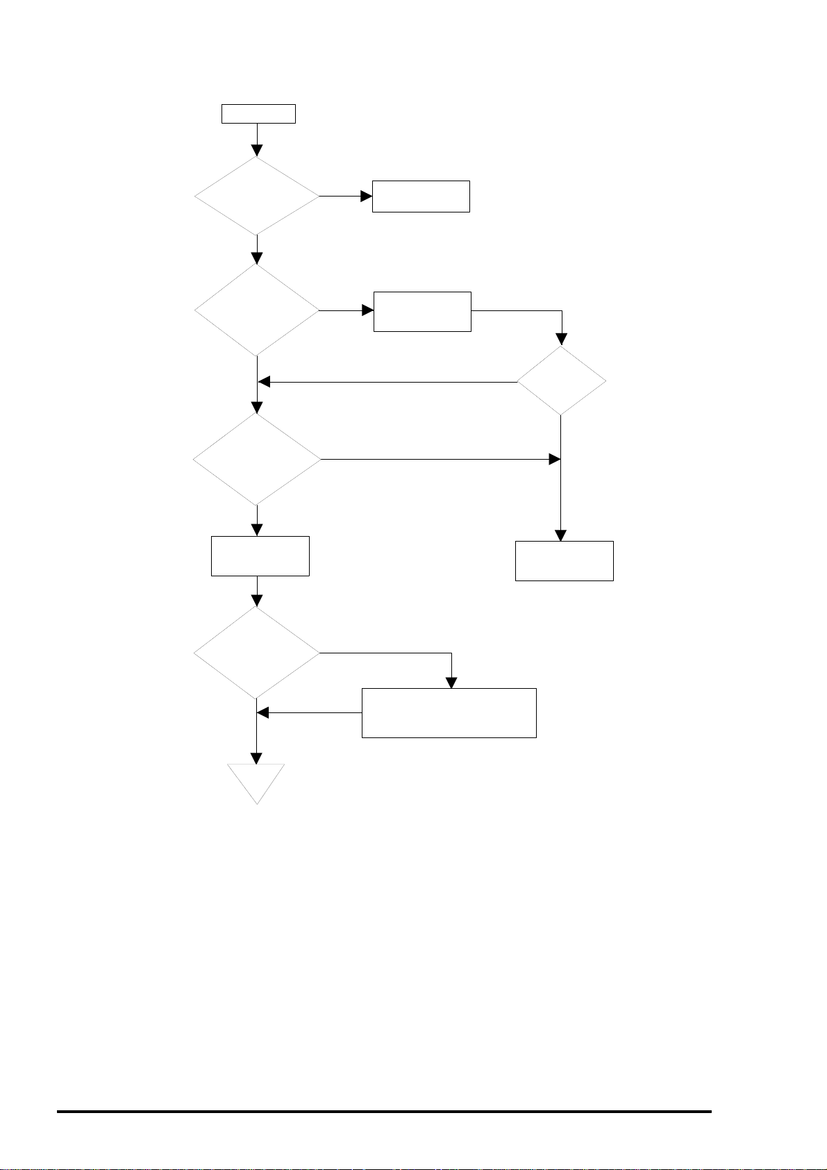
Flow Chart 1 : The printer does not operate at all.
Start
Is the AC voltage
correct?
YES
Is the fuse
F1 on the PSB/PSE
board in a good
condition ?
YES
Is the
voltage output
from the CN2 on the
PSB/PSE board
normal?
YES
Replace the MAIN
board.
NO
NO
NO
Apply correct
AC voltage.
Replace the fuse.
NO
Has the fuse
blown?
Replace the
PSB/PSE board.
YES
Is the broblem
corrected?
YES
End
NO
Check the motor and driver
circuits. Refer to the section
"Repair of the Printer Mechanism."
Figure 5-2. Flow Chart 1
5-
Rev. A
Page 6
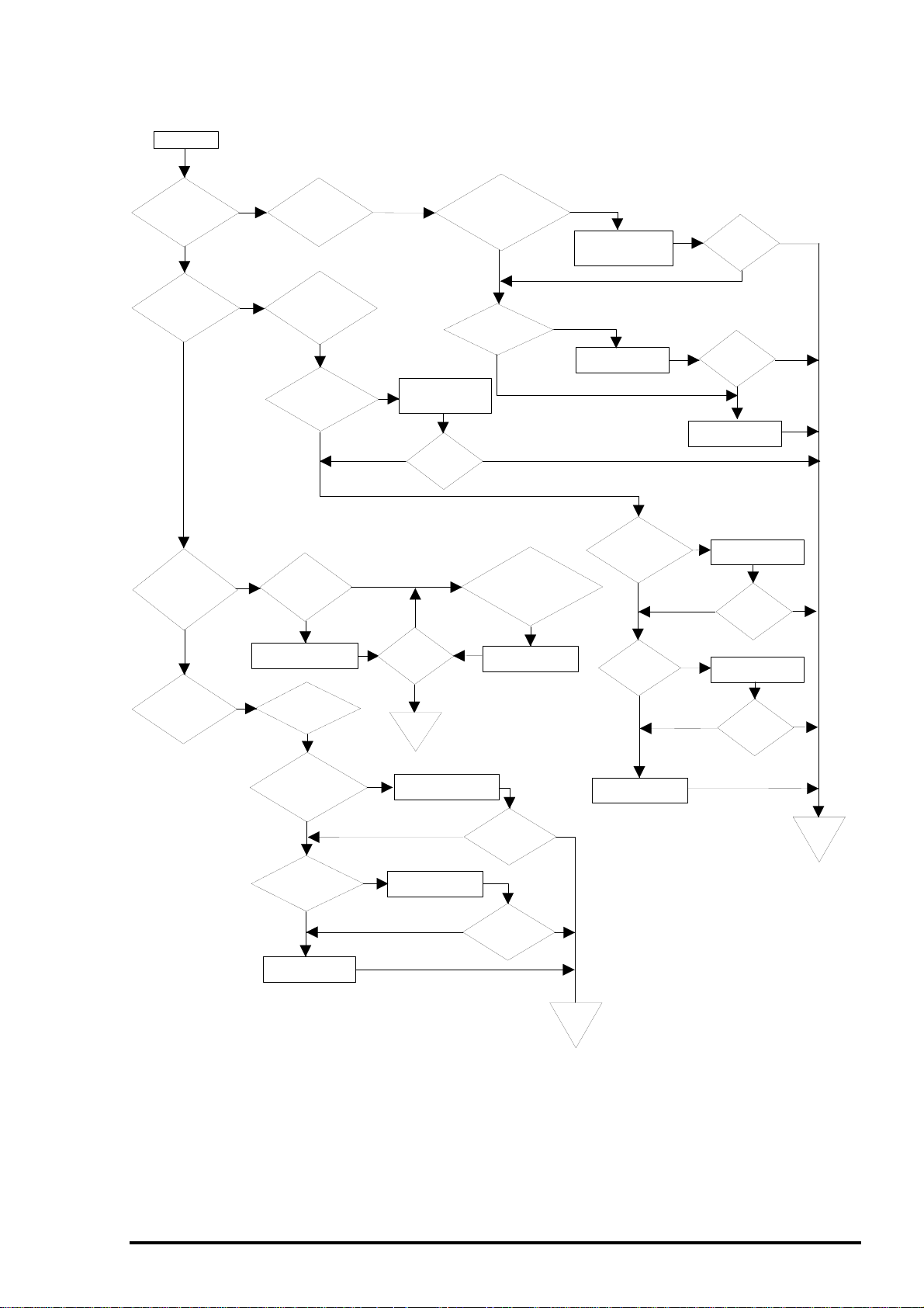
Flow Chart 2 : CR moves abnormally.
Start
Troubleshooting
Does
the CR move
when the printer is
turned on?
YES
Does
abnormal
noise occur after
printer
abnormal
noise and fatal
error occur while
turning
printer?
Is the CR
lock lever released?
is turned
on?
Does
on the
the
YES
YES
NO
occurs when the
printer is turned
NO
NO
NO
CR leaves the
home position and
stops then the fatal
error occurs?
connector securly
connected to the
Is the
cap assembly in
an abnormal
condition?
Replace the cap
assembly or reinstall it.
Does the PF
motor rotate?
Fatal error
on.
Does the
YES
Is the
HP sensor
CN6?
YES
YES
NO
NO
NO
NO
Is the
operation
normal?
End
END
Connector cable
resistance of
the CR motor
coil
Connect the HP
sensor connector
cable to the CN6.
Is the
operation
normal?
NO
YES
Is the
CR motor
Connected to
the CN12?
YES
Is the
correct?
YES
YES
Release
the CR lock
with the printer
power
Does the
off.
smoothly?
Oil the CR or clean
the CR shaft.
NO
Connect the CR motor
connector cable to the
CN12 properly.
NO
lever
CR
movemanually
NO
Replace the CR
motor.
Are
there
foreign
objects
between
sensor
the
HP
terminals?
NO
Is HP
sensor normaly
functioning?
YES
Is the
operation
normal?
NO
Is the
operation
normal?
Replace the MAIN
board.
YES
Remove the foreign
objects.
NO
NO
Replace the HP
sensor.
NO
NO
Is the
operation
normal?
Is the
operation
normal?
YES
YES
YES
YES
Is the
PF
motor connector
cable securly
connected to the
CN13?
YES
Is the
resistance of the
PF motor coil
normal?
YES
Replace the MAIN
board.
Connect the connector
cable to the CN13.
NO
NO
Replace the PF
motor.
NO
Figure 5-3. Flow Chart 2
Is the
operation
normal?
Is the
operation
normal?
YES
YES
End
END
Replace the MAIN
board.
NO
End
END
Rev. A
5-5
Page 7
EPSON Stylus
6
&2/25
800
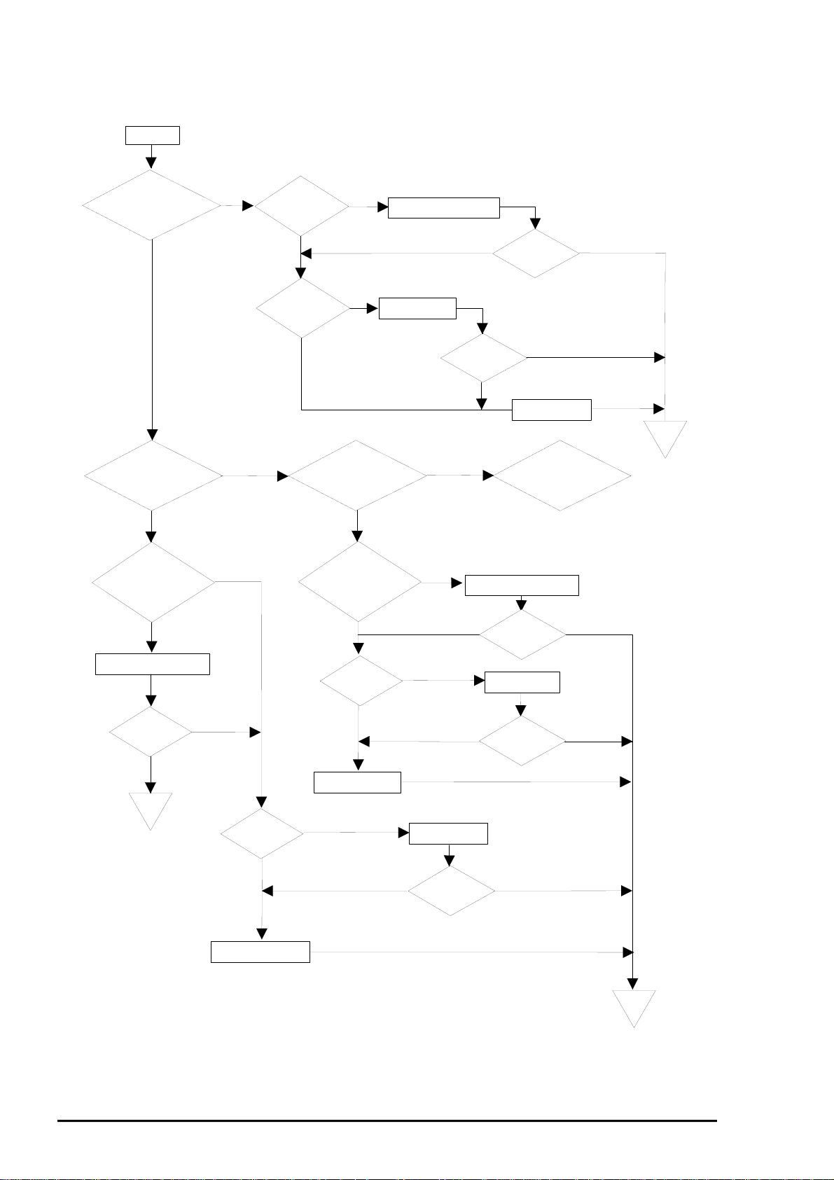
Flow Chart 3-1 : The printer feeds paper abnormally.
Start
Does
the PF roller
move when the
printer is turned on?
(CR lock is
released.)
YES
After the printer
power is turned on, the
printer repeats paper feeding
motion and indicates
the fatal error.
YES
Foreign objects are
lodged on the ASF
HP sensor.
YES
Remove the foreign objects.
Is the
operation
normal?
End
END
NO
YES
NO
NO
NO
connector cable
securely connected
resistance of the
Is the
ASF
HP sensor
functioning
properly?
YES
Is the
PF motor
to the
CN13?
YES
Is the
PF motor coil
normal?
YES
the
is turned
repeats paper
and
are lodged on the PF
sensor lever in the upper
Replace the MAIN
board.
NO
NO
NO
After
printer power
on, the printer
ejecting motion
indicates
the
fatal error.
YES
Foreign objects
paper guide
assembly.
NO
Is the
PE sensor
functioning
normally?
YES
Connect the connector cable
securly to the CN13.
NO
Replace the PF
motor.
Is the operation
normal?
NO
YES
NO
Replace the ASF
HP sensor.
NO
Remove the foreign objects.
NO
NO
Is the
operation
normal?
Is the operation
normal?
YES
NO
Replace the MAIN
board.
If the load button
is pressed or the printing
operation is activated, the
fatal error occurs.
YES
Continues to Figure 5-5 (A).
Is the
operation
normal?
Replace the PE
sensor.
Is the
operation
normal?
YES
YES
YES
End
END
Replace the MAIN board.
End
END
Figure 5-4. Flow Chart 3-1
5-
Rev. A
Page 8

Flow Chart 3-2 : The printer feeds paper abnormally.
Continued from Figure 5-4.
(A)
If the load button
is pressed or the printing
operation is activated,
the fatal error
occurs.
Yes
No
operation is activated, the
feeds paper to the
If the
load button is
pressed or the printing
and
middle way
paper empty error
occurs.
printer
Yes
Troubleshooting
Check that the connector is
connected to the CN8.
Is the
operation
normal?
No
Yes
Is the ASF/pump
motor connector cable
securly connected to the
CN11?
Is the ASF
HP sensor connector
cable securly connected
to the CN7?
Is the ASF HP sensor
functioning normally?
Replace the PE sensor.
Yes
Connect the ASF/pump motor
connector cable to the CN7.
Replace the ASF HP sensor.
Is the
operation
normal?
Yes
No
No
Replace the MAIN board.
Connect the ASF/pump motor
connector cable to the CN11.
Is the
operation
normal?
Is the
operation
normal?
Is the PE
sensor functioning
normally?
Yes
END
Is the resistance
of the ASF/pump motor
coil normal?
Is the gear (27.2)
disengaged with
the ASF LD shaft?
Engage the gear (27.2)
with the ASF LD shaft.
Is the
operation
normal?
Replace the ASF/pump motor.
Is the
operation
normal?
Replace the MAIN board.
END
Figure 5-5. Flow Chart 3-2
Rev. A
5-7
Page 9

EPSON Stylus
8
&2/25
800
Flow Chart 4-1 : Printing operation is abnormal.
Start
Does
the printer
print with the
power
on?
Yes
Perform
nozzle check
pattern.
Do all
nozzles print
properly?
Yes
Image is not clear.
Yes
Are the
head gap and
Bi-d correct?
Yes
No
No
No
No
Is the
printer in the
ink end or no
cartridge
status?
Yes
Most of the
nozzles print.
Replace the ink
cartridge.
printing
Continues to Figure 5-7 (A).
White banding
problem occurs.
Perform Head GAP timing
and Bi-d adjustment.
printing
Is the
operation
normal?
No
normal?
Yes
Yes
Is the
operation
Yes
End
Has
No
the cartrdge
been replaced
during the ink
change
sequence?
Yes
Does
the sensor
properly detect ink
cartridge
exisstence?
Yes
Yes
Replace or clean the
PF roller or gear (70).
printing
Is the
current of
the head FFC
normal?
Is the
operation
normal?
No
Are
the correct
printer driver and
paper setting
selected?
No
Use the driver for Stylus
COLOR 800 or select
the proper paper setting.
Yes
Enter the ink cartridge
No
sequence and replace
the ink cartridge again.
No
printing
No
Replace the head
unit.
No
printing
No
Replace the head
FFC.
printing
Replace the MAIN
board.
Is the
operation
normal?
Is the
operation
normal?
Is the
operation
normal?
No
Yes
Yes
No
Yes
Are
the head
angular and head
vertical
correct?
Yes
Are
the correct
printer driver and
paper setting
selected?
Yes
No
No
Perform the Head angular
and BK.-Liner adjustment.
No
Is the
printing
operation
normal?
Use the driver for Stylus
COLOR 800 or select
the proper paper setting.
Yes
Is the
printing
operation
normal?
Replace the printer
mechanism.
Is the
printing
operation
normal?
No
Replace the MAIN board.
Yes
Yes
Yes
End
Figure 5-6. Flow Chart 4-1
5-
Rev. A
Page 10

Flow Chart 4-2 : Printing operation is abnormal.
(A) Continued form Figure 5-6.
Troubleshooting
Most of the
nozzles print.
NO
YES
Perform cleaning by using
the cleaning button.
Is the
printing
normal?
NO
YES
Perform cleaning by alternating
Nozzle check in the driver utility
and the head cleaning.
(Maximum 5 times)
Go back one step and
proceed to the meshed flow.
Is
there a
PC that has
a printer driver
installed?
YES
Is the
head cleaner
properly
functioning?
NO
YES
NO
Run Self test for 1 line then
perform necessary cleaning
using the cleaning button in
the self test mode.
Is the
printing
normal?
Is the
ink left in
the EPW more
than 2/5?
Replace the head cleaner
or the pump unit.
NO
Is the
printing
normal?
YES
head cleaner
positioned?
the pump unit
absorb the
YES
NO
YES
Perfom the forciblel initial
ink charge operation in
the adjusting program.
NO
Is the
correctly
YES
Does
ink?
YES
NO
Reinstall the head
cleaner or replace it.
NO
NO
Check or replace the cap
unit or the the pump unit.
NO
Is the
printing
normal?
Is the
printing
normal?
YES
YES
End
End
Enter the ink cartridge change
sequence to install a newly
unpacked ink cartridge.
Replace the deffective
head FFC.
YES
YES
Is the
printing
normal?
Is the
printing
normal?
NO
NO
Replace the MAIN board.
Is the
printing
normal?
YES
NO
Is the
NO
current of the
head FFC
normal?
Replace the deffective
printhead.
YES
End
Rev. A
Figure 5-7. Flow Chart 4-2
5-9
Page 11

EPSON Stylus
0
&2/25
800
Flow Chart 5 : .The control panel does not function normally.
Start
Does
the power
switch
normally
operate?
Do the
buttons on the
control panel
normally
operate?
Is the FFC
properly
connected?
Check
the current
of the FFC. Is the
current
normal?
YES
YES
YES
NO
Switch on and off and check
the current between each signal
NO
line for the buttons on the control
panel and the ground using the
multimeter.
NO
NO
NO
NO
Is the
operation
normal?
Connect the panel FFC
proper ly.
Is the
operation
normal?
Replace the FFC.
NO
Is the
operation
normal?
YES
YES
YES
Switch on and off and check
the current between each signal
line for the power switch on the
control panel and the ground
using the multimeter.
Is the
operation
normal?
Is the FFC
properly
connected?
Check
the current
of the FFC. Is the
current
normal?
Is there
current between
the pin 5 of the CN4
and pin 10 of the CN5
on the MAIN
board.
YES
NO
NO
YES
NO
YES
Connect the panel FFC
proper ly.
NO
Replace the FFC.
NO
NO
Replace the MAIN
board.
Is the
operation
normal?
Is the
operation
normal?
YES
YES
Replace the MAIN board.
5-1
YES
Replace the PSB/PSE
board.
End
Figure 5-8. Flow Chart 5
NO
Is the
operation
normal?
YES
End
Rev. A
Page 12

Troubleshooting
5.4 Repair of the C202 PSB/PSE Board Component
This section describes procedures in replacing and repairing the C202 PSB/PSE board at component
level. Refer to Table 5-5 and 5-6 which list symptoms, descriptions, causes, check points, and solutions.
Table 5-5. Repair of the C202 PSB/PSE Board Component (1)
System Description Cause Check points Solution
The printer does
not operate at all.
Neither +45 V nor
+5 V is output.
F1 is open. Check visually if the F1 is in a
normal condition.
T1 is open. Check the current by using the
meter.
Q1 is dead.
• Check that there is no current
between the source and drain at
the Q1 FET.
• Check that the waveform shown
below is output form the drain of
the Q1 FET.
Replace the F1.
Replace the T1.
Replace Q1.
Q2 is
defective.
Q31 is
defective.
• Unplug the AC inlet then check
that there is no current between
the collector and emitter of the
Q2 transistor.
• Check that the switching of the
Q2 is correctly functioning with
the printer power on.
• Unplug the AC inlet then check
that there is no current between
the source and the drain of the
Q31 FET.
• Check that the switching of the
Q31FET is correctly functioning
with the printer power on.
Replace Q2, or
check if the PC1
is functioning.
Replace Q31, or
check if the PC1
is functioning.
Rev. A
5-11
Page 13

EPSON Stylus
2
System Description Cause Check points Solution
The printer does
not operate at all.
&2/25
800
Table 5-6. Repair of the C202 PSB/PSE Board Component (2)
Neither +42 V and
5v is not output.
PC1 is
defective.
• Check that there is no current
between the pins 5 and 6 or the
pins 7 and 8 for the PC1 with the
printer power on.
• Check that the waveform shown
below is output from the pin 5
and the pin 7.
Replace the
PC1.
+5V is not output. IC51 is
defective.
L51 is open.
• Check that the waveform shown
below is output form the pin7 for
the IC51.
• Check that there is current
between 2 leads of the coil for
the L51.
Replace IC51.
Replace L51.
5-1
Rev. A
Page 14

Troubleshooting
5.5 Repair of the C202 MAIN Board Component
This section consists of the procedures for replacing and repairing the C202 MAIN board at the
component level. Refer to Table 5-7 which shows symptoms, descriptions causes, check points, and
solutions.
Table 5-7. Repair of the C202 MAIN Board Component (1)
Symptom Description Cause Check points Solution
The printer does
not operate at all.
CPU is not
functioning. (The
driver mechanism
is not functioning
correctly when the
printer is turned
on and off.)
Reset IC for
the IC9 logic
is defective.
• Check that 5V is output from the
pin 1 and 3 for the IC9 at a
normal state.
Replace the
reset IC for the
IC9.
Reset IC for
the IC8 42V
line or IC19
is defective.
CRU1 or
CRU2 is
defective.
• Check that +5V is output from
the pin 6 for the IC8 and is input
to the pin1 for the IC19, and 0V
is input to the pin 2 for the IC19
and +5V is output from the pin 4
for the IC19 at a normal state.
• Check that the waveform shown
below is output from the both
leads of the CRU.
Replace the IC8
or IC19.
Replace the
defective CRU.
Rev. A
5-13
Page 15

EPSON Stylus
4
Symptom Description Cause Check points Solution
CR does not
operate properly.
&2/25
800
Table 5-8. Repair of the C202 MAIN Board Component (2)
CR does not
operate properly.
IC13 or IC2
is defective.
• Check that the driving waveform
for each phase output from the
IC13 is as shown below. The
figure below represents the
waveforms for the phase A and
phase -A.
Replace the
IC13.
Paper is not fed
properly.
PF motor does
not operate
properly.
IC1 or IC2 is
defective.
IC16 or IC2
is defective.
• Check that the CR motor phase
changeover waveform output
from the IC2 to the IC13 is as
shown below.
• Check that the drive waveform
for each phase output from the
IC16 is as shown below. The
figure below represents the
waveforms for the phase A and
phase -A.
Replace the
MAIN board.
Replace the
IC16.
5-1
Rev. A
Page 16

Troubleshooting
Table 5-9. Repair of the C202 MAIN Board Component (3)
Symptom Description Cause Check points Solution
Paper is not fed
properly.
PF motor does
not operate
properly.
IC16 or IC2
is defective.
• Check that the PF motor phase
changeover waveform output
from the IC2 to the IC16 is as
shown below.
Replace the
MAIN board.
ASF does not load
paper, or the
pump mechanism
is not driven.
ASF / pump motor
is not driven
properly.
IC6 or IC2 is
defective.
IC1 or IC2 is
defective.
• Check that the drive waveform
for each phase output from the
IC6 is as shown below. The
figure below represents the
waveforms for the phase A and
phase -A.
• Check that the ASF/pump motor
phase changeover waveform
output from the IC2 to the IC6 is
as shown below.
Replace the IC6.
Replace the
MAIN board.
Rev. A
5-15
Page 17

EPSON Stylus
&2/25
800
5.6 Repair of the Printer Mechanism
This section consists of the tables which contains symptoms, des criptions, possible causes, checkpoints ,
and solutions which you need in troubleshooting the problems with the units in the printer mechanism.
Table 5-10. Repair of the Printer Mechanism (1)
Symptom Description Possible cause Checkpoint Solution
CR does not
move properly.
Fatal error occurs when
the printer is turned on
and CR motor fails to
rotate. (No abnormal
noise is heard.)
When the printer is
turned on, the CR
moves away from the
home position. Then
the fatal error is
indicated and the CR
stops. (No abnormal
noise is head.)
When the printer is
turned on, the foreign
noise is heard and the
fatal error occurs.
When turning on the
printer or activating the
CR, abnormal noise is
heard with the fatal
error indicated then the
CR stops.
The CR motor
connector is not
properly
connected.
CR motor coil is
open.
The timing belt is
dislocated.
HP sensor
connector is
disconnected.
Foreign objects
are lodged
between the HP
sensor terminals.
HP sensor is
defective.
CR lock lever is
not released.
Oil in the CR oil
pad is dried up.
Sliding part of
the CR unit and
the top frame is
not lubricated or
foreign objects
are lodged.
Foreign objects
are lodged
between the CR
shaft and the CR
unit.
Check if the CR motor
connector cable is
properly connected to
the CN12.
Check the CR motor
coil resistance referring
to Table 5-3.
Check if the timing belt
is engaged with the CR
pinion gear or the belt
pulley.
Check if the HP sensor
connector cable is
connected to the CN6.
Check if there are
foreign objects lodged
between the HP sensor
terminals.
Check if the HP sensor
is correctly functioning
referring to Table 5-2.
1. Check the PF motor
coil resistance
referring to Table 5-3.
2. Check if the PF motor
connector cable is
connected to the
CN13.
3. Check if anything is
interfering with the CR
lock lever movement.
Release the CR lock
lever with the printer
power off and check if
the CR manually
movessmoothly.
Release the CR lock
lever with the printer
power off and check if
the CR manually
moves smoothly.
Release the CR lock
lever with the printer
power off and check if
the CR manually
moves smoothly.
Connect the CR
motor connector
cable to the CN12.
Replace the CR
motor.
Reinstall the timing
belt or replace it.
Connect the HP
sensor connector
cable to the CN6.
Remove the foreign
objects.
Replace the HP
sensor.
1. Replace the PF
motor.
2. Connect the PF
motor connector
cable to the CN13.
3. Remove the
interfering factor.
Oil the oil pad built
in the CR unit.
Oil the sliding part of
the CR unit and the
top frame, or
remove the foreign
objects.
Replace the CR oil
pad.
Clean the CR shaft
using a soft cloth.
5-16
Rev. A
Page 18

Troubleshooting
Table 5-11. Repair of the Printer Mechanism (2)
Symptom Description Possible cause Checkpoint Solution
CR does not
move properly.
Paper is not fed
properly.
When the CR returns
to the home position,
abnormal noise is
heard and the fatal
error is indicated.
PF motor does not
rotate when the printer
is powered on. (CR
lock lever is not
released and abnormal
noise is heard, then the
fatal error occurs.)
When the printer is
turned on, the printer
repeats paper loading
motion, then indicates
the fatal error.
When the printer is
turned on, the printer
repeats paper loading
motion and indicates
the paper jam error.
When the printer is
turned on, the fatal
error occurs if the load
button or printing
operation is activated.
when the printer is
turned of, the printer
starts loading paper if
the load button is
pressed or the printing
operation is activated.
But the loading motion
does not complete and
the paper empty error
occurs.
The cap in the
cap assembly
does not fit the
cap frame.
PF motor
connector cable
is disconnected.
PF motor coil is
open.
Foreign objects
are lodged
between the ASF
HP sensor
terminals.
ASF HP sensor
is defective.
Foreign objects
are lodged on
the PE sensor.
ASF/pump motor
connector cable
is disconnected.
ASF HP sensor
connector cable
is disconnected.
ASF/pump motor
coil is open.
The black gear
(27.2) on the
right edge of the
ASF is not
engaged with the
ASF LD roller
shaft.
PE sensor
connector cable
is disconnected.
Check if the cap
assembly is properly
installed.
Check if the PF motor
connector cable is
connected to the CN13.
Check the PF motor
coil resistance referring
to Table 5-3.
Check if there is foreign
object lodged between
the ASF HP sensor
terminals.
Check if the ASF HP
sensor is properly
functioning referring to
Table 5-2.
Check if foreign objects
are lodged at the PE
sensor lever and rear
paper guide.
Check if the ASF/pump
motor connector cable
is connected to the
CN11.
Check if the ASF HP
sensor connector cable
is connected to the
CN7.
Check the ASF/pump
motor coil resistan ce
referring to Table 5-3.
Check if the gear (27.2)
on the right edge of the
ASF is engaged with
the LD roller shaft.
Check if the PE sensor
connector cable is
connected to the CN8.
Reinstall the cap
assembly or replace
the cap assembly.
Connect the PF
motor connector
cable to the CN13.
Replace the PF
motor.
Remove the foreign
objects.
Replace the ASF
HP sensor.
Remove the foreign
objects.
Connect the
ASF/pump motor
connector cable to
the CN11.
Connect the ASF
HP sensor
connector cable to
the CN7.
Replace the
ASF/pump motor.
Reinstall the gear
(27.2).
Connect the PE
sensor connector
cable to the CN8.
Rev. A
5-17
Page 19

EPSON Stylus
8
Symptom Description Possible cause Checkpoint Solution
Paper is not fed
properly.
Abnormal
printing
&2/25
800
Table 5-12. Repair of the Printer Mechanism (3)
ASF repeats paper
loading motion but the
paper is not loaded.
The last sheet of the
paper in ASF is not
loaded.
OHP sheet is not
loaded.
Paper out or Ink end
error occurs when
turning on the printer
despite the cartridge is
new.
All dots or most of the
dots in the nozzle
check pattern are not
printed.
Cleaning is performed
5 times or a newly
unpacked ink cartridge
is installed, but all dots
or most of the dots are.
not printed in the
Nozzle check pattern
ASF LD roller is
worn or paper
dust is lodged.
The guide sheet
is not placed.
OHP adapter is
not used.
Ink consumption
counter is not
reset since the
cartridge was not
replaced during
the ink cartridge
change
sequence.
The ink cartridge
sensor is
defective.
Head FFC is
disconnected.
Head FFC is
damaged.
Bubbles in the
cavity.
Head FFC is
disconnected.
Head FFC is
damaged.
The head
cleaner has not
contact with the
head.
Check the surface of
the LD roller.
Check if the
appropriate guide sheet
is used.
Check if the OHP
adapter is mounted or
is correctly used.
Check if the sensor is
functioning referring to
Table 5-2.
Check if the head FFC
is connected to the
CN9 or CN10.
Check current of the
pin 1 of each head
FFC.
Check if the head FFC
is connected to the
CN9 or CN10.
Check the current of
the each FFC.
Check if the head
cleaner is in contact
with the head with the
proper portion.
Replace the LD
roller.
Use the appropriate
guide sheet.
Use the OHP
adapter correctly.
Enter the ink
cartridge change
sequence again to
replace the ink
cartridge.
Replace the
printhead.
Connect the correct
FFC to the CN9 or
CN10.
Replace the head
FFC.
1. Alternate cleaning
and printing
operation.(Printer
driver utility is
useful.)
2. If the ink left in the
EPW is more than
2/5, perform the
initial ink charge
sequence in the
adjusting program.
3. Enter the ink
cartridge change
sequence to install
a newly unpacked
ink cartridge.
Connect the correct
FFC to the CN9 or
CN10.
Replace the head
FFC.
1. Adjust the head
cleaner position.
2. Replace the head
cleaner.
3. Adjust the platen
gap.
5-1
Rev. A
Page 20

Troubleshooting
Table 5-13. Repair of the Printer Mechanism (4)
Symptom Description Possible cause Checkpoint Solution
Abnormal
printing
Cleaning is performed
5 times or a newly
unpacked ink cartridge
is installed, but all dots
or most of the dots are
not printed in the nozzle
check pattern.
White banding
appears.
Image is not clear. Head gap or Bi-d
Pump unit does
not absorb the
ink.
Printhead is
defective.
Dot missing Check the nozzle
PF roller is worn
or is smudged
with the ink.
Some teeth of
the gear (70)
broke off or the
gear is not
engaged with the
PF roller shaft
properly.
The driven roller
on the upper
paper guide is
worn or the
torsion spring
(117.6) has luck
of sufficient
tension.
is no adjusted
adequately.
Head angular or
head vertical is
not adjusted
properly.
PG is too wide. Check the position of
Dot missing Check if the nozzles
1. Check if the ink
absorb tubes are
properly connected to
the cap assembly.
2. Check if the ink
absorb tubes are
twisted or damaged.
3. Check if the rubber
part of the cap
assembly is
deformed.
4. Check if the air valve
in the cap assembly is
damaged.
(In case the problem
still occurs after
attempting all the
checkpoints mentioned
above.)
condition by performing
Nozzle check.
Check the surface of
the PF roller.
Check the teeth of the
gear (70).
Check if the gear (70)
rotates constantly with
the torque form the PF
motor.
Check if the surface of
the driven roller on the
upper paper guide is
blakish or is lodged
with foreign
objects.Check if the
torsion spring is
deformed or hooked
securely.
Check the head gap
and Bi-d status by
using the printer driver
utility, adjusting
program, or control
panel.
Refer to 4-12 and 4-15
in Chapter 4.
the PG lever.
are clogged by
performing Nozzle
check.
1. Connect the ink
absorb tubes to
the cap assembly
properly.
2. Replace the ink
absorb tubes or
the pump unit.
3. Replace the cap
assembly.
4. Replace the air
valve or the cap
assembly.
Replace the
printhead.
Refer to the solution
described in the
previous page.
Clean the PF roller
surface or replace
the PF roller.
Replace the gear
(70) or reinstall the
gear (70) properly.
Replace the driven
roller or the torsion
spring.
Remove the foreign
objects from the
surface of the driven
roller.
Perform adjusting
using the adjusting
utilities and
programs.
Refer to 4-12 and 415 in Chapter 4.
Set the lever to “0”.
Refer to the
corresponding
solution in the
previous page.
Rev. A
5-19
Page 21

EPSON Stylus
0
Symptom Description Possible cause Checkpoint Solution
Abnormal
printing
&2/25
800
Table 5-14. Repair of the Printer Mechanism (5)
Ink smudge Ink on the driven
roller of the
upper paper
guide or other
paper paths.
PG is too narrow
or the paper
loaded does not
meet the
specification.
Feed plain paper and
check if it gets ink
smudge.
Check the position of
the PF lever.
Check the paper
thickens.
Clean the spot
stained with the ink.
Set the PG lever to
“+”.
Use the paper that
meets the
specification.
5-2
Rev. A
 Loading...