

Page 1

Chapter 1
Product Description
1.1 Features..............................................................................................................1-1
1.2 Accessories and Options..................................................................................1-2
1.3 Hardware Specifications...................................................................................1-3
1.3.1 Printing Specifications................................................................................1-3
1.3.2 Print Speed and Printable Columns...........................................................1-3
1.3.3 Paper Feeding..............................................................................................1-4
1.3.4 Paper Specifications...................................................................................1-4
1.3.4.1 Cut Sheets..........................................................................................................................1-4
1.3.4.2 Transparencies, Glossy Paper............................................................................................1-4
1.3.4.3 Envelopes...........................................................................................................................1-4
1.3.4.4 Index Cards.........................................................................................................................1-4
1.3.5 1.3.5 Printable Area....................................................................................1-5
1.3.6 ASF Paper Capacity.....................................................................................1-6
1.3.7 Ink Specifications........................................................................................1-7
1.3.8 Electric Specifications................................................................................1-8
1.3.9 Reliability......................................................................................................1-8
1.3.10 Safety Approvals........................................................................................1-8
1.3.11 CE Marking.................................................................................................1-8
1.3.12 Acoustic Noise...........................................................................................1-8
1.3.13 Environmental Conditions........................................................................1-9
1.3.14 Physical Specifications.............................................................................1-9
1.4 Firmware Specifications.................................................................................1-10
1.4.1 Control Codes and Character Specifications..........................................1-10
1.4.2 Input Data Buffer........................................................................................1-12
1.5 Interfaces..........................................................................................................1-13
1.5.1 Parallel Interface (Forward Channel)......................................................................................1-13
1.5.2 Parallel Interface (Reverse Channel).....................................................................................1-16
1.5.3 Mac Serial Interface................................................................................................................1-17
1.5.4 Optional Interface....................................................................................................................1-18
1.5.5 Preventing Hosts from Data Transfer Timeout.......................................................................1-18
1.5.6 Interface Selection.....................................................................................1-18
1.6 Operations........................................................................................................1-19
1.6.1 Control Panel.............................................................................................1-19
1.6.2 Default Settings.........................................................................................1-21
1.6.3 Printer Adjustment Mode..........................................................................1-23
1.6.4 Ink Smudge Prevention Mode..................................................................1-23
1.6.5 EEPROM Clear Mode.................................................................................1-23
1.6.6 Printer Initialization...................................................................................1-24
1.6.7 Initialization Items and Values..................................................................1-25
1.6.8 Self-test Function......................................................................................1-26
1.6.9 Hexadecimal Dump Function...................................................................1-26
1.6.10 Error Conditions......................................................................................1-26
1.6.11 Monochrome Printing Mode...................................................................1-26
Page 2

1.7 Main Components...........................................................................................1-27
1.7.1 C202 MAIN Board......................................................................................1-28
1.7.2 C202 PSB/PSE Board................................................................................1-29
1.7.3 C202 Panel Board......................................................................................1-30
1.7.4 Printer Mechanism....................................................................................1-30
1.7.5 Housing......................................................................................................1-31
Page 3
Product Description
1.1 Features
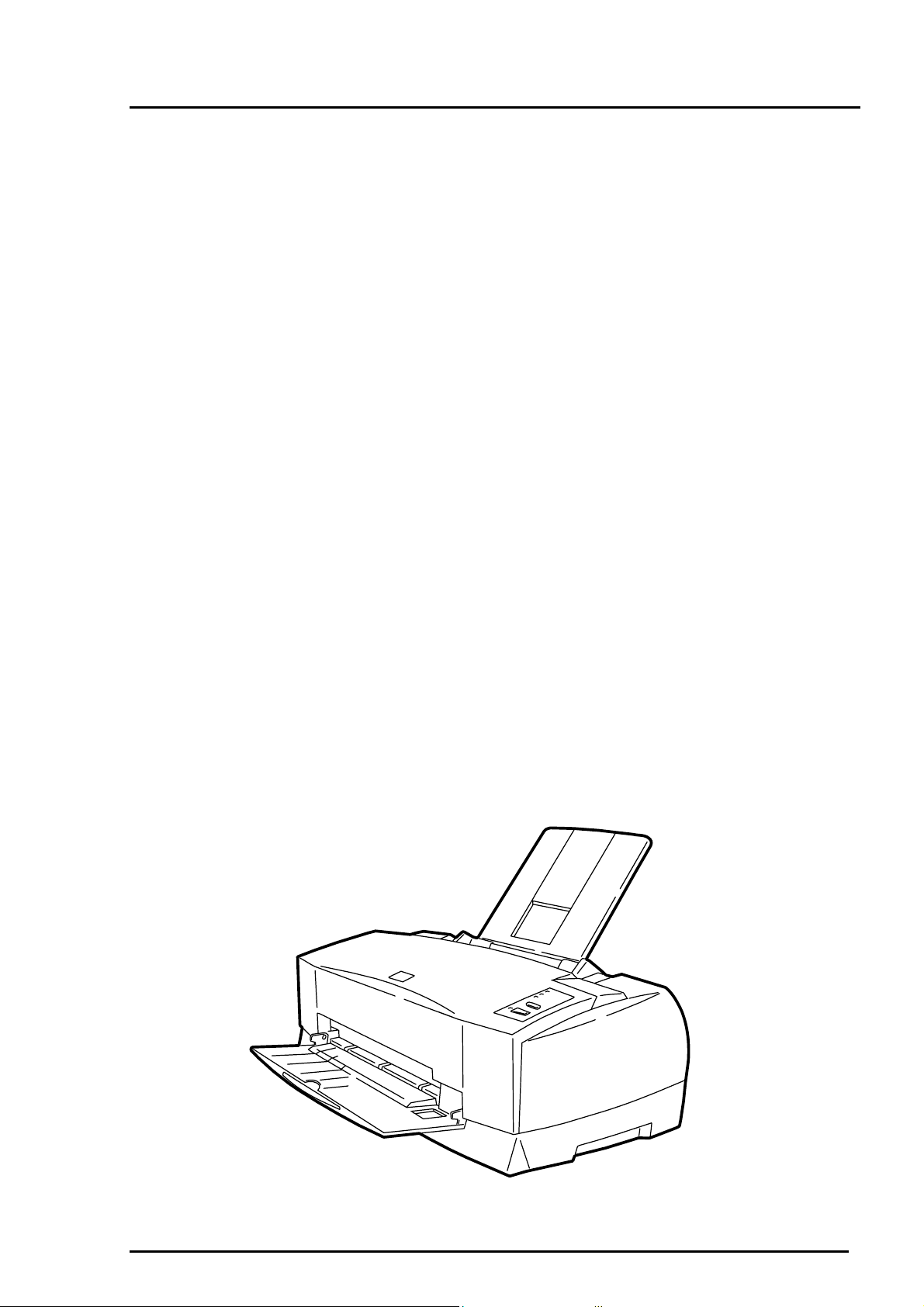
The EPSON Stylus COLOR 800 is a high-performance color ink jet printer designed for the small
office/home office (SOHO) market. The main features of this printer are:
High print quality for color graphics
High resolution 1440 (H) x 720 (V) dpi printing
Colors Cyan, Magenta, Yellow, Black
Printing method Traditional and new Microweave printing
Smaller dot diameter for image improvement
High-speed printing
400 cps in LQ mode
533 cps in Draft mode
Built-in auto sheet feeder with a wide page capability and high capacity
This printer holds: 100 cut-sheets (55 g/m
10 envelopes
20 sheets of glossy paper
30 index cards
50 transparency film sheets
70 sheets of special paper
2 interfaces built-in and 1 optional interface card
Mac serial interface (up to approximately 900K bps)
Bidirectional parallel interface (IEEE-1284 level 1 device)
Optional Type-B interface card
4 scalable fonts and 5 LQ fonts:
Scalable fonts Roman T, Sans Serif H, Roman, Sans Serif
LQ fonts Roman, Sans Serif, Courier, Prestige, Script
9 usable character tables (NLSP version)
Italic, PC437, PC850, PC437 Greek, PC852, PC853, PC855, PC857,
PC866, PC869, MAZOWIA, Code MJK, ISO 8559-7, Latin 1T, Bulgaria,
PC774, Estonia, ISO 8859-2, PC866 LAT
2
)
Rev. A
Figure 1- 1. Exterior View of Stylus COLOR 800
1-1
Page 4
EPSON Stylus
2
&2/25
800
1.2 Accessories and Options
Table 1-1. Accessories
Part Number Description Quantity
4006678
5020108
5020089
Table 1-2. Options and Consumables
Part Number Description Quantity
C82305/C82306
C82307/C82308
C82310∗
C82313∗
C82315∗
C82314∗
C82312∗
C82331∗
C82345∗
C836021∗
C83603∗
C83604∗
C83605∗
C83606∗
S020108
S020089
S041059
S041025 200 sheets
S041060
S041061
S041026 200 sheets
S041062
S041067
S041054
S041121
S041122
S041071
S041072
S041107
S041126
S041124
S041063
S041064
S041106
Serial interface card
32KB serial interface
32KB parallel interface card
32KB EEE-488 interface card
TWAIN interface card
Coax interface card
LocalTalk™ interface card
Ethernet interface card
Type B bidirectional parallel interface card
Parallel interface cable (shielded) from D-SUB 25-pin to
Amphenol 57
Serial interface cable from D-SUB 25-pin to D-SUB 25pin
Serial interface cable from D-SUB 9-pin to D-SUB 25-pin
Black ink cartridge
Color ink cartridge
EPSON 360 dpi ink jet paper (A4)
EPSON 360 dpi ink jet paper (Letter)
EPSON photo-quality Ink jet paper (A4)
EPSON photo-quality ink jet paper (Letter)
EPSON photo-quality ink jet paper (Legal)
EPSON photo-quality ink jet card (A6)
EPSON photo-quality ink jet card (5.8 inches)
EPSON photo-quality ink jet card (10.8 inches)
EPSON photo-quality glossy film (A4)
EPSON photo-quality glossy film (Letter)
EPSON photo-quality glossy film (A6)
EPSON photo-quality glossy paper (A4)
EPSON photo-quality glossy paper (Letter)
EPSON ink jet transparencies (A4)
EPSON ink jet transparencies (Letter)
EPSON photo-quality self-adhesive sheets (A4)
Note: Asterisk in a part number replaces the last digit of the part number, which varies by
country.
User’s Guide 1
Ink Cartridge (Black) 1
Ink Cartridge (Color) 1
CD ROM (Printer Driver, Utility) 1
100 sheets
100 sheets
100 sheets
100 sheets
100 sheets
50 sheets
15 sheets
15 sheets
10 sheets
30 sheets
30 sheets
10 sheets
1-
Rev. A
Page 5
1.3 Hardware Specifications
1.3.1 Printing Specifications
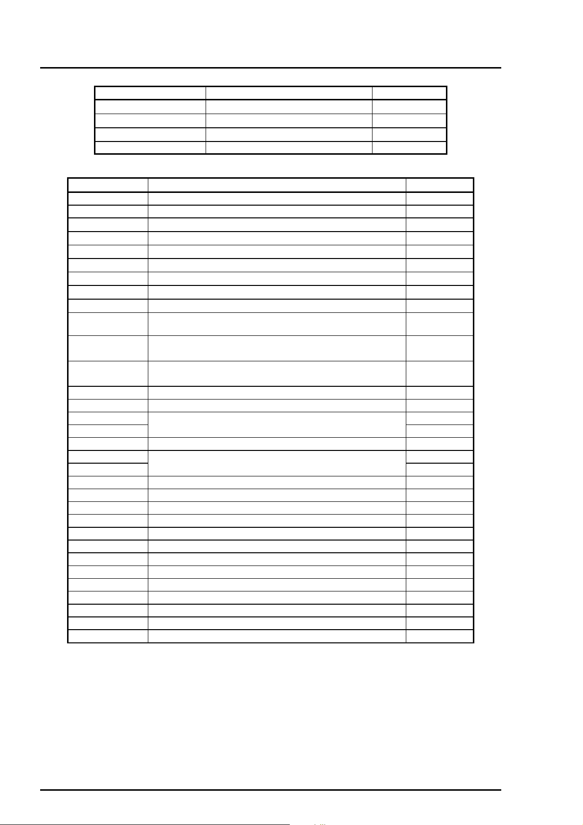
Print method
Nozzle configuration
32/360 inch
On-demand ink jet
Monochrome 128 nozzles (32 x 4 staggered)
Color (magenta, cyan, yellow) 64 nozzles (32 X 2 staggered,
144/360 inch
32/360 inch
#127#128
#125#126
32/360 inch
144/360 inch
#64
each color)
32/360 inch
#63
320/360 inch
#64
144/360 inch
#63
Product Description
32/360 inch
#64
#63
#2 #3#4#1
Black
Paper feed direction
#2
Cyan
Figure 1- 2. Nozzle Configuration
Print direction
Bidirectional with logic-seeking
1.3.2 Print Speed and Printable Columns
Table 1-3. Print Speed and Printable Columns in Character Mode
Character Pitch Printable
Columns
10 cpi (Pica) 80 400 cps 533 cps
12 cpi (Elite) 96 480 cps 640 cps
15 cpi 120 600 cps 800 cps
17 cpi (Pica condensed) 137 684 cps 912 cps
20 cpi (Elite condensed) 160 800 cps 1067 cps
Table 1-4. Print Speed and Printable Area for Raster Graphics Mode
Print Mode Printable Area Available Dots CR Speed
180 dpi x 180 dpi 8.27 inch 1488 26.7 ips
360 dpi x 360 dpi 8.27 inch 2976 20 ips
720 dpi x 720 dpi 8.27 inch 5952 20 ips
1440 dpi x 720 dpi *
1
8.27 inch
#1
#2
Magenta
#1
#2
Yellow
LQ Speed Draft Speed
5952 *
2
10 ips
#1
Rev. A
*1: Printing at 1440 x 720 dpi is available only using the Microweave driver.
*2: Can be printed by sending following command sequence:
1. Set print speed to 10 ips.
2. Print a 180 x 720 raster image.
3. Advance the paper using an increment of 31/720 inch.
4. Move the print position horizontally using an increment of 1/1440 inch.
5. Print a 180 x 720 raster image.
6. Advance the paper using an increment of 31/720 inch.
7. Repeat steps 2 to 6.
1-3
Page 6
EPSON Stylus
4
&2/25
800
1.3.3 Paper Feeding
Paper Transport Method
Line Spacing
Paper Path
Feeding Speed
1.3.4 Paper Specifications
1.3.4.1 Cut Sheets
Table 1-4. Cut Sheet Specifications
Size Width Length
A4
Letter
B5
Legal
Half Letter
Exclusive
A5
210 mm (8.3”) 297 mm (11.7”)
216 mm (8.5”) 279 mm (11.0”)
182 mm (7.2”) 257 mm (10.1”)
216 mm (8.5”) 356 mm (14.0”)
139.7 mm (5.5”) 215.9 mm (8.5”)
185.2 mm (7.25”) 266.7 mm (10.5”)
148.5 mm (5.8”) 210 mm (8.3”)
Friction feed with built-in auto sheet feeder (ASF)
1/6, 1/8, or programmable at 1/360 inch
Top entry (ASF) with semi straight paper path
1/3 inch100 ms
Continuous 5.0 inches per second
Thickness
Paper Weight
Quality
0.08 mm (0.003”) to 0.11 mm (0.004”)
64 g/m
Exclusive paper, bond paper, PPC
2
(17 lb.) to 90 g/m2 (24 lb.)
1.3.4.2 Transparencies, Glossy Paper
Table 1-5. Transparency Size
Size Width Length
Thickness
A4
Letter
210 mm (8.3”) 297 mm (11.7”)
216 mm (8.5”) 279 mm (11.0”)
0.075 mm (0.003”) to 0.085 mm (0.0033”)
Note: Printing on transparencies is available only at normal temperatures.
1.3.4.3 Envelopes
Table 1-6. Envelope Size
Size Width Length
No.10 241 mm (9 1/2”) 104 mm (4 1/8”)
DL 220 mm (8.7”) 110 mm (4.3”)
C6 114 mm(4.5”) 162 mm (6.4”)
Thickness
Paper Weight
Quality
Note: 1. Printing on envelopes is only available at normal temperatures.
2. Insert the longer side of the envelope horizontally.
0.16 mm (0.006”) to 0.43 mm (0.02”)
45 g/m
Bond paper, Plain paper, Airmail
2
(12 lb.) to 90 g/m2 (24 lb.)
1.3.4.4 Index Cards
Table 1-7. Index Card Size
Size Width Length
A6 index card 105 mm (4.1”) 148 mm (5.8)
5” X 8” 127 mm (52) 203 mm (8”)
8” X 10” 203 mm (8”) 254 mm(10”)
Thickness
1-
Less than 0.23 mm (0.0091”)
Rev. A
Page 7
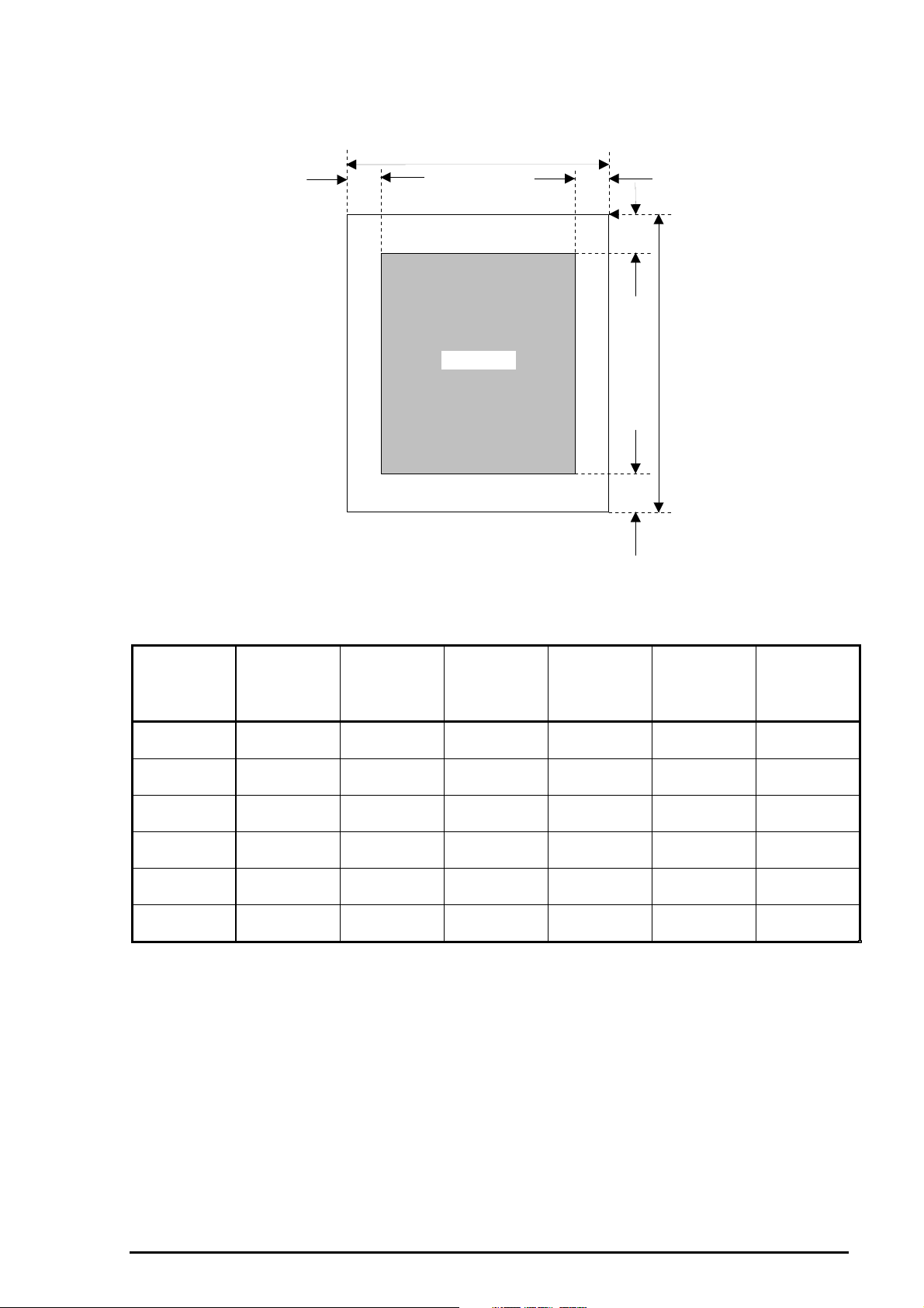
1.3.5 Printable Area
Cut Sheets
Product Description
PW
LM RM
TM
PW
Paper Size
(Paper
Width)
(typical)
A4 210 mm
(8.3”)
Letter 216 mm
(8.5“)
B5 182 mm
(7.2“)
Legal (L) 216 mm
(8.5“)
Statement 139.7 mm
(5.5“)
Executive 190.5 mm
(7.5“)
Printable Area
BM
Table 1-8. Margins for Different Cut Sheet Sizes
Figure 1- 3. Printable Area for Cut Sheets
PL (Paper
Length)
(typical)
297 mm
(11.7”)
279 mm
(11.7“)
257 mm
(10.1“)
536 mm
(14.0“)
215.9 mm
(8.5“)
254 mm
(10“)
LM (Left
Margin)
(Minimum)
3 mm
(0.12”)
3 mm
(0.12”)
3 mm
(0.12”)
3 mm
(0.12”)
3 mm
(0.12”)
3 mm
(0.12”)
RM (Right
Margin)
(Minimum)
3 mm
(0.12”)
*1
9 mm
(0.35”)
3 mm
(0.12”)
9 mm *
1
(0.35”)
3 mm
(0.12”)
3 mm
(0.12”)
(Top Margin)
PL
TM
(Minimum)
3 mm
(0.12”)
3 mm
(0.12”)
3 mm
(0.12”)
3 mm
(0.12”)
3 mm
(0.12”)
3 mm
(0.12”)
BM (Bottom
Margin)
(Minimum)
14 mm
(0.54”)
14 mm
(0.54”)
14 mm
(0.54”)
14 mm
(0.54”)
14 mm
(0.54”)
14 mm
(0.54”)
*1: 3 mm (0.35”) in raster graphics mode.
Rev. A
1-5
Page 8
EPSON Stylus
6
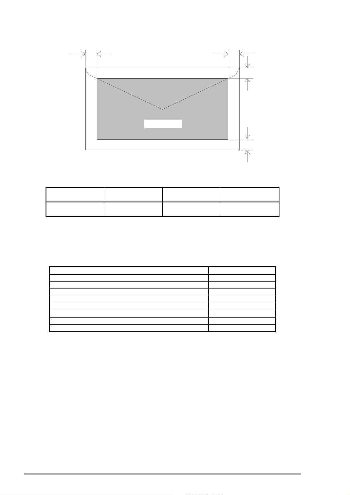
Envelopes
&2/25
800
LM
LM
(Left Margin)
3 mm
(0.12”)
Printable area
Figure 1- 4. Printable Area for Envelopes
Table 1-9. Minimum Margins for Envelopes
RM
(Right Margin)
3 mm
(0.12”)
TM
(Top Margin)
3 mm
(0.12”)
RM
TM
BM
BM
(Bottom Margin)
14 mm
(0.55”)
1.3.6 ASF Paper Capacity
The following table shows the maximum capacity for each paper type you can load in the ASF.
Table 1-10. ASF Paper Capacity
Paper Capacity
Plain paper (64 g/m2) 100 sheets
EPSON photo-quality paper 65 sheets
EPSON 360 dpi paper 65 sheets
EPSON photo-quality glossy paper 20 sheets
EPSON photo-quality glossy film 30 sheets *1 *
EPSON ink jet transparencies 30 sheets *
EPSON photo-quality cards 30 sheets *
EPSON photo-quality self-adhesive sheets 1 sheet
*1. When 30 sheets are loaded in the ASF, you must set the TOP margin to more than
30 mm. Otherwise you must load the paper sheet by sheet.
*2. Depending on the paper, you must set the paper feed guide sheet for the last sheet
in the ASF.
2
1
2
1-
Rev. A
Page 9
1.3.7 Ink Specifications
Black Ink Cartridge
Table 1-11. Black Ink Cartridge Specifications
Black Ink Cartridge
Type Exclusive cartridge
Color Black (Quick Penetration)
Print Capacity 900 pages / A4 (ISO/IEC 10561 Letter Pattern at 360 dpi)
Ink life 2 years from indicated production date
Storage Temperatures
Dimensions 30 mm (W) x 58 mm (D) x 38.5 mm (H)
*1 The cartridge must not be kept at 40° C (104° F)for more than a month.
*2 The cartridge must not be kept at 60° C (140° F) for more than 120 hours.
Note:
1. Do not refill the cartridge. The ink cartridge is a consumable item.
2. Do not use a cartridge whose ink life has expired.
3. Ink freezes below –4° C (23° F); however it will be usable again after keeping it
for more than 3 hours at room temperature.
Storage –20 to 40° C (–4 to 104° F)
Storage (packed) –30 to 40° C (–22 to 104° F)
In transit (packed) –30 to 60° C (–22 to 140° F)
(1.18” x 2.28” x 1.51”)
Product Description
* 1
* 1
* 1 *2
Color Ink Cartridge
Table 1-12. Color Ink Cartridge Specifications
Color Ink Cartridge
Type Exclusive cartridge
Color Magenta, Cyan, Yellow (Quick Penetration)
Print Capacity 300 pages A4 (at 360 dpi, 5% duty each color)
Ink life 2 years from indicated production date
Storage Temperatures
Storage –20 to 40° C (–4 to 104° F)
Storage (packed) –30 to 40° C (–22 to 104° F)
In transit (packed) –30 to 60° C (–22 to 140° F)
Dimensions 42.9 mm (W) X 52.7 mm (D) X 38.5 mm (H)
(1.68”X 2.07” X 1.51”)
*1 Do not keep the cartridge at 40° C (104° F) for more than a month.
*2 Do not keep the cartridge at 60° C (140° F) for more than 120 hours.
Note:
1. Do not refill the cartridge. The ink cartridge is a consumable item.
2. Do not use a cartridge whose ink life has expired.
3. Ink freezes below –4° C (23° F); however it will be usable again after keeping it
for more than 3 hours at room temperature.
* 1
* 1
* 1 *2
Rev. A
1-7
Page 10

EPSON Stylus
8
&2/25
800
1.3.8 Electric Specifications
120 V Version
Rated voltage 120 VAC
Input voltage range 103.5 to 132 VAC
Rated frequency range 50 to 60 Hz
Input frequency range 49.5 to 60.5 Hz
Rated current 0.4 A (Maximum 0.5A)
Power consumption Approximately 18 W (ISO/IEC 10561 Letter pattern)
Energy star compliant
Insulation resistance 10M ohms, min. (between AC line and chassis, 500 VDC)
Dielectric strength 1,000 VAC rms. for 1 minute or
1,200 VAC rms. for 1 second (between AC line and chassis)
220-240 V Version
Rated voltage 220 to 240 VAC
Input voltage range 198 to 264 VAC
Rated frequency range 50 to 60 Hz
Input frequency range 49.5 to 60.5 Hz
Rated current 0.2 A (Maximum 0.3A)
Power consumption Approximately 18 W (ISO/IEC 10561 Letter pattern)
Insulation resistance 10M ohms, min. (between AC line and chassis, 500 VDC)
Energy star complinat
Dielectric strength 1,500 VAC rms. for 1 minute (between AC line and chassis)
1.3.9 Reliability
Total Print Volume
Printhead Life
75,000 pages (A4/Letter)
2,000 million dots /nozzle
1.3.10 Safety Approvals
120 V Version
Safety standards UL1950 with D3
CSA C22.2 No.950 with D3
EMI FCC part15 subpart B class B
CSA C108.8 class B
220 - 240 V Version
Safety standards EN 60950 (VDE, NEMKO)
EMI EN 55022 (CISPR Pub.22) class B
AS/NZS 3548 class B
1.3.11 CE Marking
220 - 240 V Version
Low Voltage Detection 73/23/EEC EN 60950
EMC Detection 89/336/EEC EN 55022 class B
EN 61000-3-2
EN 61000-3-3
EN 50082-1
IEC801-2
IEC801-3
IEC801-4
1.3.12 Acoustic Noise
Noise level
1-
Approximately 51 dB (A) (According to ISO 7779)
Rev. A
Page 11

1.3.13 Environmental Conditions
Temperature
Operating 10 to 35 *
Storage –20 to 40° C (–4 to 104° F) (for less than 1 month at 40°) *
Transit –20 to 60° C (–4 to 140° F) (for less than 120 hours at 60°)
1
Product Description
2
Humidity
Operating 20% to 80% (without condensation) *
Non operating 5% to 85% (without condensation) *
Resistance to Vibration
Operating 0.15 G *
2
Non-operating 0.50 G
Resistance to Shock
Operating 1 G within 1 ms*
2
Non-operating 2 G within 2 ms
Humidity (%)
90
80
70
60
50
40
30
20
Operating environment
1
2
C
10 20
(50 H)
Figure 1- 5. Environmental Conditions
*1 :Refer to the table above.
*2 :In shipment container.
1.3.14 Physical Specifications
Weight
Dimensions
6.5 kg
475 mm (W) x 274 mm (D) x 177 mm (H) (18.7” x 10.78” x 6.96”)
C
27
(80 H)
30
C
C
35
C
(95 H)
Temperature ( )
40
C
C
Rev. A
1-9
Page 12

EPSON Stylus
0
&2/25
800
1.4 Firmware Specifications
1.4.1 Contr ol Codes and Character Specifications
Control Codes
Character Tables
Standard version (11 character tables)
Italic table PC 437 (US, Standard Europe)
PC 850 (Multilingual) PC 860 (Portuguese)
PC 861 (Icelandic) PC 863 (Canadian-French)
PC 865 (Nordic) Abicomp
BRASCII Roman 8
ISO Latin 1
NLSP version (19 character tables)
Italic table PC850 (Multilingual)
PC 437 (US, Standard Europe) PC 437 (Greek)
PC 852 (East Europe) PC 853 (Turkish)
PC 855 (Cyrillic) PC 857 (Turkish)
PC 866 (Russian) PC 869 (Greek)
MAZOWIA (Poland) Code MJK (CSFR)
ISO 8559-7 (Latin, Greek) ISO Latin 1T (Turkish)
Bulgaria (Bulgaria) PC 774
Estonia ISO8859-2 (ISOLatin2)
PC 866 LAT
ESC P/2
EPSON remote command
IBM X 24E emulation
Legal and 14 international character sets
1-1
Rev. A
Page 13

Typefaces
Bitmap LQ fonts
EPSON Roman 10 cpi, 12 cpi, 15 cpi, Proportional
EPSON Sans Serif 10 cpi, 12 cpi, 15 cpi, Proportional
EPSON Courier 10 cpi, 12 cpi, 15 cpi
EPSON Prestige 10 cpi, 12 cpi, 15 cpi
EPSON Script 10 cpi, 12 cpi, 15 cpi
Scalable fonts
EPSON Roman 10.5 pt.; 8 pt. to 32 pt. (2 pt. increments)
EPSON Sans Serif 10.5 pt.; 8 pt. to 32 pt. (2 pt. increments)
EPSON Roman T 10.5 pt.; 8 pt. to 32 pt. (2 pt. increments)
EPSON Sans Serif H 10.5 pt.; 8 pt. to 32 pt. (2 pt. increments)
Note: Each typeface has 4 variations: Normal, Bold, Italic, and Bold Italic
An example of variations for EPSON Roman is as follows:
EPSON Roman normal
EPSON Roman bold
EPSON Roman italic
EPSON Roman bold italic
Product Description
Rev. A
1-11
Page 14

EPSON Stylus
2
Combinations of Character Tables and Typefaces
Standard
Version
NLSP
Version
&2/25
800
Table 1-13. Character Tables and Fonts
Character Tables Bitmap Fonts Scalable Fonts Scalable Fonts
EPSON Roman
EPSON Sans Serif
EPSON Courier
EPSON Prestige
EPSON Script
Italic table
PC 437 (US Standard
Europe)
PC 850 (Multilingual)
PC 860 (Portuguese)
PC 861 (Icelandic)
PC 863 (Canadian-French)
PC 865 (Nordic)
BRASCII
Abicomp
Roman 8
ISO Latin 1
Italic table
PC 437 (US Standard
Europe)
PC 850 (Multilingual)
PC 437 (Greek)
PC 852 (East Europe)
PC 853 (Turkish)
PC 855 (Cyrillic)
PC 857 (Turkish)
PC 866 (Russian)
PC 869 (Greek)
MAZOWIA (Poland)
Code MJK (CSFR)
ISO 8859-7 (Latin/Greek)
ISO Latin 1T (Turkish)
Bulgaria (Bulgaria)
PC 774
Estonia
ISO 8859-2 (ISO Latin 2)
PC 866 LAT
Supported Supported Supported
Supported Supported Not Supported
EPSON Roman
EPSON Sans
Serif
EPSON Roman T
EPSON Sans Serif H
Supported
1.4.2 I nput Data Buffer
Capacity 32KB
1-1
Rev. A
Page 15

Product Description
1.5 Interfaces
The EPSON Stylus COLOR 800 is equipped with two interfaces: parallel and Mac serial interface, and a
card slot for an optional Type-B interface. This section provides information on each interface.
1.5.1 Parallel Interface (Forward Channel)
Transmission Mode
Synchronization
Handshaking
Signal Level
Table 1-14. Signal Level for TTL-Compatible IEEE-1284 Level 1 Device
Parameter Minimum Maximum Condition
VOH* — 5.5 V
VOL* –0.5 V —
IOH* — 0.32 mA VOH = 2.4 V
IOL* — 12 mA VOL = 0.4 V
CO — 50 pF
VIH — 2.0 V
VIL 0.8 V —
IIH — 0.32 mA VIH = 2.0 V
IIL — 12 mA VIL = 0.8 V
CI — 60 pF
Notes: * A LOW logic level on the Logic H signal line is as follows:
2.0 V or less when the printer is powered off.
3.0 V or more when the printer is powered on.
The receiver provides an impedance equivalent to 7.5K ohms to ground.
8-bit parallel, IEEE-P1284 compatibility mode
/STROBE pulse
BUSY and /ACKNLG signal
TTL compatible level (IEEE-P1284 Level 1 device)
Refer to Table 1-15.
Adaptable Connector
The BUSY signal is set HIGH before setting either /ERROR LOW or PE HIGH, and held HIGH until all
these signals return to an inactive state. The BUSY signal is HIGH in the following cases:
During data entry.
When the input data buffer is full.
While /INIT signal is at a LOW level or during hardware initialization.
During a printer error condition (See the /ERROR signal).
During test printing.
When the printer is in default setting mode.
When the parallel interface is not selected.
57-30360 (Amphenol) or equivalent
Rev. A
1-13
Page 16

EPSON Stylus
4
&2/25
800
The ERROR signal is at a LOW level when one of the following errors has occurred:
Printer hardware error (fatal error)
Paper-out error
Paper-jam error
Ink-out error
The PE signal is HIGH during a paper-out error.
Data Transmission Timing (Forward Channel)
Table 1-15. Data Transmission Timing
Parameter Minimum Maximum
tsetup 500 ns —
thold 500 ns —
tstb 500 ns —
tready 0 —
tbusy — 500 ns
tt-out — 120 ns
tt-in — 200 ns
treply — —
tack 500 ns 10 µs
tnbusy 0 —
tnext 0 —
Note: tt-out shows the rise and fall time of every output signal.
tt-in shows the rise and fall time of every input signal.
DATA
STROBE
BUSY
ACKNLG
data byte n data byte n+1
thold
tsetup
tstb
treply
tack tnbusy
Figure 1- 6. Data Transmission Timing
tnext
1-1
Rev. A
Page 17

Connector Pin Assignments and Signals
Table 1-16. Connector Pin Assignments and Signals (Forward Channel)
Pin No. Signal Name Return
GND Pin
1
2-9
10
11
12
13
14
31
32
36
18
35
17
16,33,19-30
15,34
1.
/STROBE
2.
DATA 0-7
3.
/ACKNLG
4.
BUSY
5.
PE
6.
SLCT
7.
/AFXT
8.
/INIT
9.
/ERROR
10.
/SLIN
11.
Logic H
12.
+5V
13.
Chassis
GND
14.
GND
15.
NC
19 I The STROBE pulse. Reading in of data is
20-27 I The DATA 0 to DATA 7 signals represent
28 O This signal is a negative pulse indicating that
29 O When this signal is at a HIGH level, the
28 O When this sign is at a HIGH level, the paper
28 O Always at HIGH level when the printer is
30 I Not used.
30 I The falling edge of a negative pulse or a
29 O When the printer detects an error, this
30 I Not used.
— O Pulled up to +5 V via 3.9K-ohm resistor.
— O Pulled up to +5 V via 3.3K-ohm resistor.
— — Chassis ground.
— — Signal ground.
— — Not connected.
Product Description
I/O Description
performed at the falling edge of this pulse.
data bits 0 to 7, respectively. Each signal is
at a HIGH level when data is logical 1 and a
LOW level when data is logical 0.
the printer can again accept data.
printer is not ready to accept data.
empty status is detected.
powered on.
LOW signal on this line causes the printer to
initialize. Minimum 50 µs pulse is
necessary.
signal goes LOW.
Note: 1. / at the beginning of a signal means active LOW.
2. The I/O column indicates the direction of the signal as viewed from the printer.
Rev. A
1-15
Page 18

EPSON Stylus
&2/25
800
1.5.2 Parallel Interface (Reverse Channel)
Transmission Mode
Adaptable Connector
Synchronization
Handshaking
Data Transmission Timing
Signal Level
Extensibility Request
The printer accepts a request when the extensibility request value is 00H or 04H. The description of
each value is as follows:
00HRequest nibble mode reverse channel transfer
04HRequest to return Device ID using nibble mode reverse channel transfer.
Device ID
The printer sends following device ID string upon request:
[00H] [43H]
MFG EPSON
CMD ESCPL2E, PRPXL, BDC
MDL STYLUS[SP]COLOR[SP]800
CLS PRINTER
Note: [00H] denotes a hexadecimal value of zero.
IEEE-1284 nibble mode
Same as the forward channel
Refer to the IEEE-1284 specification
Refer to the IEEE-1284 specification
Refer to the IEEE-1284 specification
IEEE-1284 level 1 device (See forward channel.)
Table 1-18 shows pin assignments and signals for the parallel interface reverse channel.
Table 1-17. Connector Pin Assignments and Signals (Reverse Channel)
Pin No. Signal Name Return
GND Pin
1 HostClk 19 I Clock signal from the host computer.
2-9 DATA 0-7 20-27 I These signals represent parallel data on bits
10 PtrClk 28 O Clock signal from the printer
11 PtrBusy/
Data bits 3,7
12 AckDataReq/
Data Bits 2,6
13 Xflag/Data bits 1, 5 28 O X flag signal. Data bits 1 or 5 in reverse
14 Host Busy 30 I Busy signal from the host computer
31 /INIT 30 I Not used
32 /Data Avail/
Data Bit 0,4
36 1284-Active 30 I 1284 active signal.
18 Logic-H — O Pulled up to +5 V via 3.9K-ohm resistor.
35 +5V — O Pulled up to +5 V via 3.3K-ohm resistor.
17 Chassis GND — — Chassis ground for the printer.
16, 33, 19-30 GND — — Signal ground.
15, 34 NC — — Not connected.
29 O Busy signal from the printer. Data bits 3 or 7
28 O Acknowledge request signal. Data bits 2 or 6
29 O Data available signal. Data bits 0 or 4 in
I/O Description
2 to 9. Each signal is HIGH when the data is
logical 1 and LOW when the data is logical 0.
in reverse channel.
in reverse channel.
channel.
reverse channel.
Note: 1. The symbol / at the beginning of a signal means active LOW.
2. The I/O column indicates the direction of the signal as viewed from the printer.
1-16
Rev. A
Page 19

1.5.3 Mac Serial Interface
Standard
Synchronization
Bit Rate
Word Format
Data bits 8 bit
Handshaking
Adaptable Connector
Recommended I/F Cable
Table 1-18. Connector Pin Assignments for Serial Interface
Pin No. Signal Name I/O Functional Description
1 SCLK O Synchronous clock
2 CTS I Clear to send
3 TxD- O Transmit data 4 S.G. I Signal ground
5 RxD- I Receive data 6 TxD+ O Balanced transmit +
7 DTR O Data terminal ready
8 RxD+ I Balanced receive +
Product Description
RS-423 compliant
Synchronous
Approximately 900Kbps/1.8 Mbps
Start bit 1 bit
Parity bit No parity bit
Stop bit 1 bit
X-ON/X-OFF, DTR protocol
8-pin mini circular connector
Apple System Peripheral-8 cables
Note: Refer to the figure below for the connector pin arrangement.
8
7
5
2
Table 1-19. X-ON/X-OFF, DTR Protocol
State Buffer space X-ON/X-OFF DTR
Busy Less than 1024 bytes Send X-OFF code Off
Ready More than 2048 bytes Send X-ON code On
Figure 1- 7. Serial I/F Pin Assignments
6
34
1
Rev. A
1-17
Page 20

EPSON Stylus
&2/25
800
1.5.4 Optional Interface
The Stylus COLOR 800 supports an optional Type-B interface (Level 2) with the following characteristics.
Reply Message
When ESC/P 2 mode is selected:
Main type MTP48p, PW136cl10cpi, PRG(W0xxxx)rev, SPD0fast
Product name Stylus COLOR 800
Emulation type ESCPL2-00
Entity type EPSONLQ2
When IBM X24E is selected:
Main type MTP48p, PW136cl10cpi, PRG(W0xxxx)rev, SPD0fast
Product name Stylus COLOR 800
Emulation type PRPXL24-00
Entity type EPSONPRPXL24
1.5.5 Preventing Hosts from Data Transfer Timeout
Generally, hosts abandon data transfer to peripherals when a peripheral is BUSY continuously for dozens
of seconds. To prevent this kind of timeout, the printer receives data very slowly, several bytes per minute,
even the printer is in a busy state. This slowdown starts when the remainder of the input buffer drops
under several hundred bytes. Finally, the printer is BUSY continuously when the input buffer is full.
1.5.6 Interface Selection
The Stylus COLOR 800 can have three types of interfaces: parallel, serial, and optional Type-B. Each
interface can be selected manually or automatically. Both modes are selected through default setting
mode.
Manual Selection
One of 3 interfaces selected through the default setting mode. The selected interface is fixed.
Automatic Selection
Automatic interface selection is enabled in default setting mode. In automatic interface selection mode,
the printer is initialized to the idle state when it is powered on (*1) scanning which interface is to receive
data. Then the interface that receives data first is selected. When the host stops data transfer and the
printer is in the standby state for a number of seconds, the printer returns to the idle state. As long as the
host sends data or the printer interface is busy state, the selected interface is left as it is.
*1: No interface is selected in this state.
Interface Selection and Interface State
When an interface other than the parallel interface is selected, the parallel interface goes into the
BUSY state.
When the interface other than serial interface is selected, the serial interface sets the DTR signal
MARK.
When the printer is initialized and returned to idle state, the parallel interface goes into ready state
and the serial interface sets the DTR signal SPACE.
Note: An interrupt signal such as the INIT on the parallel interface is ignored while that interface is not
selected.
1-18
Rev. A
Page 21

Product Description
1.6 Operations
This section describes the functions of each button on the control panel and LED printer status indicators.
1.6.1 Control Panel
The control panel for this printer consists of 3 non-lock pushbuttons, 1 lock type pushbutton, and 4 LED
indicators. Refer to Figure 1-8.
(b)
(c)
(d)
(3)
(4)
Figure 1- 8. Control Panel
Panel Description
See Table 1-21 for the panel buttons and LED descriptions.
Table 1-20. Panel Buttons and LED Descriptions
Buttons LEDs
1234abcd
Description
Color
Panel Functions (Normal Usage)
Power Load/EjectCleaning
(Black)
Cleaning
(Color)
(a)
(2)
(1)
Power Paper Out Ink Out
(Black)
Green Red Red Red
Ink Out
(Color)
Rev. A
Table 1-21. Panel Functions
Buttons Functions
Load/Eject
Cleaning (Black)
(Press for 2 seconds)
Cleaning (Color)
(Press for 2 seconds)
Cleaning (Black)
+
Cleaning (Color)
(Press for 2 seconds)
*1: Only effective when the printer is in the ink cartridge change mode.
*2: Only effective when the printer is in the
Loads or ejects paper.
Exits ink cartridge change mode.*
Performs black ink cartridge cleaning.
Enters ink cartridge change mode. *
Performs color ink cartridge cleaning.
Enters ink cartridge change mode. *
Enters ink cartridge change mode.
In the ink cartridge change mode, the carriage moves to
the black cartridge change position by pressing
“Cleaning (Black)” button.
In the ink cartridge change mode, the carriage moves to
the color cartridge change position by pressing
“Cleaning (Color)” button.
Ink Low
or
Ink Out
1
condition.
2
2
1-19
Page 22

EPSON Stylus
0
&2/25
800
Panel Functions at Power On
This printer also enters various functions by holding down a specific button and turning on the printer.
Each combination and its function are described in Table 1-23.
Table 1-22. Panel Function with Power On
Button Pressed *
1
Function
(while turning on the printer)
Load /Eject
Cleaning (Black)
Cleaning (Color)
Load /Eject + Cleaning (Color)
Load /Eject + Cleaning (Black)
Cleaning (Black) + Cleaning (Color)
Load /Eject
+
Starts LQ self-test printing.
Starts Draft self-test printing.
Enters default setting mode.
Enters Hex-dump mode.
Enters the printhead alignment mode.
Enters ink smudge prevention mode.
Resets a specific area of EEPROM and
Timer IC.*
2
Cleaning (Black)
+
Cleaning (Color)
Then press Cleaning (Color) button
once again within 3 seconds.
*1
: ”+” means to press one button while holding down the other button(s).
*2:
Refer to Table 1-28 or the EEPROM map described in the Appendix.
LED Indicators
Several printer conditions can be identified by LEDs on the control panel. Which LED (or LEDs) lights
varies, depending on the condition. See Table 1-24 for printer conditions and LED status.
Table 1-23. Printer Conditions and LED Status
Indicators
Printer Condition Power Ink out
Power on condition On
(Black)
1
---*
Ink out
(Color)
--- --Ink sequence Blinks --- --- --Ink cartridge change mode Blinks --- --- --Data processing Blinks --- --- --Paper out --- --- --- On
Paper jam --- --- --- Blinks
No ink cartridge or ink end (black) --- On --- --Ink level low (black) --- Blinks --- --No ink cartridge or ink end (color) --- --- On --Ink level low (color) --- --- Blinks --Enter EEPROM and Timer IC reset On
1 second
On
1 second
Maintenance request Blinks Blinks Blinks Blinks
Fatal error Blinks Blinks On On
*1: “---” means no effect.
Paper Out
On
1 second
1-2
Rev. A
Page 23

Product Description
1.6.2 Default Settings
The printer enters default setting mode when you press the
printer. The menus available for this printer are shown in Table 1-25.
Table 1-24. Default Setting Menus
Menu Setting *
Print direction*
2
Font
Auto
/ Bi-d / Uni-D
Roman / Sans Serif /
Courier
Roman T / Sans Serif H / Draft
Pitch
I/F mode
Auto I/F wait mode
Software
Auto CR (IBM mode only)
AGM (IBM mode only)
Character tables
Standard version
10 cpi
Auto
10 seconds
ESC/P2
On /
On /
/ 12 cpi / 15 cpi / 17.1 cpi / 20 cpi / Proportional
/ Parallel / Mac Serial / Option
/ 30 seconds
/ IBM X24E
Off
Off
Italic USA, Italic France
Italic Germany, Italic U.K.
Italic Denmark, Italic Sweden
Italic Italy, Italic Spain 1
PC 437
, PC 850
PC 860, PC 863
PC 865, PC 861
BRASCII, Abicomp
Roman 8, ISO Latin 1
Character tables
NLSP version
Italic USA, Italic France
Italic Germany, Italic U.K.
Italic Denmark, Italic Sweden
Italic Italy, Italic Spain 1
PC 437
, PC 437 (Greek)
PC 850, PC 853
PC 855, PC 852
PC 857, PC 866
PC 869, MOZOAWIA
Code MJK, ISO 8559-7
ISO Latin 1T, Bulgaria
PC 774, Estonia
ISO 8859-2, PC 866 LAT
Auto line feed
On /
Off
Network I/F mode This mode is for network environment.
Off
: Used in usual environment
On: Used in network environment
Loading position
Economy mode
Parallel I/F transfer rate
3 mm /
On /
Fast
8.5 mm
Off
/ Normal
/ Others *
*1: Underlined parameters in bold letters are factory default settings.
*2: Refer to the following tables 1-26, 1-27.
*3: This is selected when a value other than 3 mm / 8.5 mm is set into EEPROM with the
command.
Table 1-25. Print Direction Mode Characteristics
Black and White Printing CMYK Printing (Color)
Auto Throughput and quality is better.Throughput is better.
Bi-D Throughput is the best.
Print quality may be down.
Uni-D Throughput is worse.
Print quality is the best.
Cleaning (Color)
button while turning on the
1
/ Prestige / Script/
3
Color quality with special paper is worse.
(Color correction depends on the print
direction.
Throughput is the best.
Color quality with special paper is worse.
(Color correction depends on the print
direction.)
Throughput is worse.
Color quality is the best.
ESC l
Rev. A
1-21
Page 24

EPSON Stylus
2
Default
Setting Mode
*1 Printing direction is controlled by a driver in the Windows / Mac environment.
Setting Method
1.
See the flowchart below for the default setting method.
&2/25
800
Table 1-26. Printing Direction and ESC U Command
Character Mode
(for DOS)
Raster Graphics Mode
(for Windows / Mac)*1
ESC U 0 Auto Bi-D
Auto ESC U 1 Auto Uni-D
ESC U 2 Auto Auto
Auto Auto
ESC U 0 Bi-D Bi-D
Bi-D ESC U 1 Uni-D Uni-D
ESC U 2 Auto Auto
Bi-D Bi-D
ESC U 0 Uni-D Bi-D
Uni-D ESC U 1 Uni-D Uni-D
ESC U 2 Uni-D Auto
Uni-D Uni-D
Start
Hold down the "Cleaning(Color)"
button, and turn on the printer.
The printer prints:
1. Firmwear version number
Method of selecting the language
2.
for "Usage of this mode"
Select the desirable language by
pressing the "Cleaning(Black)"
Then press the "Cleaning(Color)" button.
The printer prints:
1. The latest settings
2. "Usage of this mode"
Change the settings?
button.
YES
NO
Select the setting menu : "Cleaning(Color)" button
Change the setting value : "Load/Eject" button
Memorize the new setting : "Cleaning(Color)" button
More change ?
NO
Turn the printer off once to save the new setting(s) into the EEPROM.
YES
Figure 1-9. Default Setting Flowchart
1-2
Rev. A
Page 25

Product Description
1.6.3 Printhead Alignment Mode
The Stylus COLOR 800 allows users to perform printhead alignment operation without a special program.
The following list shows adjustments performed for this printer.
Table 1-27. Printer Adjustment Patterns
Pattern No. Menu
1 Bi-d adjustment (533 cps, units: 1-720 inch)
2 Bi-d adjustment at (400 cps, units: 720 inch)
3 Head gap adjustment in main scan direction — from left to right (400 cps, 720 units/inch)
3 Head gap adjustment in main scan direction — from left to right (200 cps, 720 units/inch)
Adjustment Method
1.
Press the
2.
The printer prints the adjustment method on A4 paper.
Load/Eject
Cleaning (Black)
and
buttons while turning on the printer.
3.
Look at the tests printed along with the instruction and press the
until the panel lights indicate the appropriate test number.
4.
Print the adjustment pattern by pressing the
5.
Look at the test patterns on the new printout and press the
panel lights indicate the test pattern that is most
6.
Press the
7.
Repeat steps 3 to 6 as many times as needed to properly align all the test patterns on the
printouts.
8.
Turn off the printer.
Load/Eject
button.
Load/Eject
button.
Cleaning (Black)
Cleaning (Color)
button
button until the
1.6.4 Ink Smudge Prevention Mode
When the printer is in this mode, the carriage remains at the edge of the carriage for extra time before
each return. This extra time allows ink to dry enough to avoid ink smudges caused by bleeding and ink
contact with the paper. Note this function is designed as a response to any customer’s complaint and is
not described in the user’s guide. Also, it is necessary to acknowledge to customers in advance that this
mode does not provide the fastest throughput for the printer. The printer goes into this mode when you
press the
Cleaning (Black)
Cleaning (Color)
and
buttons while turning on the printer.
1.6.5 EEPROM Clear Mode
This mode is used to reset a specific area of EEPROM. Press the
Cleaning (Color)
seconds. The
operation. The addresses initialized are specified, and there is no panel operation that initializes data of
other addresses in the EEPROM. Table1-29 lists the specified addresses and their descriptions.
buttons while turning on the printer; then press the
Paper Out, Ink Out (Black)
Ink Out (Color)
, and
Load/Eject, Cleaning (Black)
Cleaning (Color)
LEDs light for 1 second during the
button within 3
, and
Table 1-28. EEPROM Clear Items
EEPROM Addresses (Hex) Data Name Factory Values
22H Interface 00H Auto
6CH / 6DH Protection Counter A 00H / 00H
52H / 53H Color Cleaning Timer 00H / 00H
62H / 63H Black Cleaning Timer 00H / 00H
6EH / 6FH Power Off Time 00H / 00H
Rev. A
1-23
Page 26

EPSON Stylus
&2/25
800
1.6.6 Printer Initialization
This printer has the following three initialization types: Power-on initialization, Operator initialization, and
Software initialization.
Power-on Initialization
Triggers Turning on the printer
Cold reset command (remote RS command).
Actions performed:
Initializes the printer mechanism.
Clears input data buffer.
Clears download character set.
Clears print buffer.
Refer to Section 1.5.7,
Operator Initialization
Triggers Turning the printer off and back on again within 10 seconds
The printer recognizes the INIT signal (negative pulse) on the
parallel interface.
Actions performed
Clears input data buffer.
Clears download character set.
Clears print buffer.
Refer to
Software Initialization
Trigger ESC @ command
Actions performed
Clears print buffer.
Refer to
Initialization Items and Values
Initialization Items and Values
Initialization Items and Values
1-24
Rev. A
Page 27

Product Description
1.6.7 Initialization Items and Values
The values used when this printer is initialized are described under
the default setting mode or the remote control codes are, however, stored as initialization values only after
power off. On the other hand, values set by other methods are cleared at power off, and the printer returns
to the initialization values shown in the table when the printer is initialized.
Table 1-29. Initialization Values
Initialization Item Default Set
by Panel Operation?
Print direction Y Y Auto
Font Y Y Courier
Pitch N Y 10 cpi
I/F Y Y Auto
Auto I/F wait mode Y Y 10 seconds
Software Y N ESC/P 2
Auto CR (IBM mode only) Y Y Off
AGM (IBM mode only) Y Y Off
Character table Y Y PC437
Character table for NLSP Y Y PC437
Auto line feed Y Y OFF
Network I/F mode Y N Off
Loading position Y Y 8.5 mm
Economy mode Y Y OFF
Parallel l/F mode Y N Fast
Line spacing N E 4.23 mm (1/6 inch)
Page length N Y Maximum
EPSON Control Codes? Factory Value
Default Settings
. Values set through
Y: Stored after the printer is powered Off.
E: Effective only while printer power is On.
N: Cannot change.
Rev. A
1-25
Page 28

EPSON Stylus
&2/25
800
1.6.8 Self-test Function
Pressing the
self-test mode. The self-test is used to check the following:
Control circuit function
Printer mechanism function
Print quality
Turn off the printer to exit this mode.
Load/Eject
Cleaning (Black)
or
button while turning on the printer puts the printer in the
1.6.9 Hexadecimal Dump Function
Pressing the
hexadecimal dump mode. Each line has Hexadecimal codes, along with their corresponding letters printed
in the right column. If a received code denotes an unprintable character, such as a control code, “.”
(period) is printed in the right column. This function enables users to check whether the data from the host
is properly transferred. Turn off the printer to exit the mode.
Load/Eject
Cleaning (Color)
and
buttons while turning on the printer activates the
1.6.10 Error Conditions
This printer is in an error condition when any error in Table 1-31 is detected.
Table 1-30. Error Conditions
Error Name Detection Trigger
Fatal error The carriage moves abnormally.
The carriage does not move.
Paper out / paper jam error No paper is loaded.
Paper is jamming.
Ink end error An ink cartridge is not installed.
Ink end.
Maintenance error Waste ink has exceeded the specified amount.
1.6.11 Monochrome Printing Mode
This printer has 3 printing modes:
Default mode
Color mode
Monochrome mode
Each mode is selected according to printer condition, as described below.
Default Mode
Color mode is selected automatically when both black and color cartridges are installed
and no ink end error has occurred. When color ink ends, the printer can go into
monochrome print mode. It is, however, switched by turning the printer off and back on
again, or by sending the INIT signal.
Default mode is selected when the printer is initialized.
Color Mode
The printer prints normally, based on whether print data is black or color.
Can be selected through the printer driver.
Monochrome Mode
The printer prints all data in black only. Color data selection (
mode. After the printer goes into monochrome print mode, you can return it to color mode
by turning the printer off and back on or sending an INIT signal after replacing the color
cartridge. This mode is also selected through the printer driver. In this case, it is used,
regardless of the color ink consumption, because this mode is defined by the
command.
ESC r
) is ignored in this
ESC r
1-26
Rev. A
Page 29

1.7 Main Components
The main components of the Stylus COLOR 800 are:
Main control board C202 MAIN board
Power supply board C202 PSB/PSE board
Control panel bard C202 panel board
Printer mechanism
Housing
The following figure shows the main component layout of the Stylus COLOR 800.
Product Description
Housing
C202 PNL Board Assembly
C202 MAIN Board Assembly
C202 PSB/PSE Board Assembly
Printer Mechanism
Figure 1-10. Stylus COLOR 800 Component Layout
Rev. A
1-27
Page 30

EPSON Stylus
&2/25
800
1.7.1 C202 MAIN Board
The C202 MAIN board controls various printer operations. It consists of an HD6432653 CPU (128-pin,
19.66 MHz), ASIC E05B33CB (208-pin, 19.66 MHz), 8M-bit-type PROM (42-pin, including CG data) or
8M-bit-type PROM + 8M-bit-type CG (NLSP version only), 4M-bit-type DRAM, EEPROM, and several
drivers. Because this board is installed into the slot in the rear cover of the printer using 2 screws and
several connectors, it is easily removed and installed.
IC17
Black head common
Driver IC
Motor driver IC
UDN2917
IC18
Color head common
driver IC
IC2 ASIC
E05B33C
IC11
EEPROM
IC12
Parallel I/F Circuit IC
Figure 1-11. C202 MAIN Board
IC1 CPU
C090A02CB
IC3
P-ROM
IC15
Mac Serial
Transceiver IC
IC5
DRAM
IC7
CG
IC20
Timer IC
1-28
Rev. A
Page 31

Product Description
1.7.2 C202 PSB/PSE Board
This board consists of a transformer, switching FET, regulator IC, diode bridge, photo coupler, fuse,
various transistors, and so on. It supplies C202 MAIN board with +5 V and +35 V.
Switching
FET Q1
Transformaer
T1
DB1
Photo Coupler
PC1
F1 FuseDiode Bridge
Figure 1-12. C202 PSB/PSE Board
IC51
CN2
CN1
Rev. A
1-29
Page 32

EPSON Stylus
&2/25
800
1.7.3 C202 Panel Board
The C202 panel board is the control panel for the Stylus COLOR 800. It has 4 buttons including the power
button and 4 LEDs.
EPSON
Figure 1-13. C202 Panel Board
C202PNL
1.7.4 Printer Mechanism
This printer mechanism consists of monochrome / color heads; motors, such as the ASF motor, CR
motor, and PF motor; sensors, such as the HP sensor, PE sensor, ASF HP sensor, Black Cartridge Out
detection sensor, and Color Cartridge Out detection sensor, thermistor, and a pump unit.
1-30
Figure 1-14. Printer Mechanism
Rev. A
Page 33

1.7.5 Housing
This printer consists of the printer cover, upper housing, and lower housing.
Printer Cover
Upper Housing
Product Description
Figure 1-15. Housing
Lower Housing
Rev. A
1-31
 Loading...