

Page 1

Chapter 3
Disassembly and Assembly
3.1 Overview................................................................................................................3-1
3.1.1 Precautions for Disassembling the Printer......................................................... 3-1
3.2 Disassembly and Assembly Procedures............................................................3-3
3.2.1 Before Beginning Disassembly........................................................................... 3-4
3.3 C202 MAIN Board Assembly Removal................................................................3-5
3.4 Upper Housing Removal......................................................................................3-6
3.4.1 C202 Panel Board Assembly Removal................................................................ 3-9
3.5 Printhead Removal.............................................................................................3-10
3.6 Paper Eject Frame Assembly Removal.............................................................3-13
3.7 Front Paper Guide Assembly Removal.............................................................3-14
3.8 Home Position (HP) Sensor Removal...............................................................3-15
3.9 C202 PSB/PSE Board Assembly Removal .......................................................3-16
3.10 Carriage Motor (CR Motor) Assembly Removal.............................................3-18
3.11 ASF (Auto Sheet Feeder) Removal..................................................................3-19
3.11.1 ASF Assembly Disassembly- ........................................................................... 3-21
3.11.2 ASF HP Sensor Removal.................................................................................. 3-26
3.12 Paper Feed Motor Assembly Removal............................................................3-28
3.13 Printer Mechanism Removal............................................................................3-30
3.13.1 Cap Assembly Removal....................................................................................3-31
3.13.2 Pump Assembly Removal................................................................................ 3-33
3.13.3 Pump Motor Removal....................................................................................... 3-35
3.13.4 Carriage (CR) Assembly Removal ................................................................... 3-36
3.13.5 Top Frame Removal.......................................................................................... 3-40
3.13.6 Paper Empty (PE) Sensor Assembly Removal................................................ 3-42
3.13.7 I/S (Ink System) Frame Removal...................................................................... 3-44
3.13.7.1 I/S Frame Disassembly (Removing the Pump Motor)............................ 3-47
3.13.8 Paper Feed Roller (PF Roller) Assembly Removal......................................... 3-51
3.13.9 Ink Drain Pad Removal.....................................................................................3-54
Page 2
Disassembly and Assembly
3.1 Overview
This section describes procedures for disassem bling main components of the EPSON Stylus
COLOR 800. Unless otherwise specified, you can assemble units or components by reversing
disassembly. Therefore, no assembly procedures are included. Pr ecautions for disassembly or
assembly are described under the heading
assembling the unit are described under
3.1.1 Precautions for Disassembling the Printer
See the precaution below when disassembling and assembling EPSON Stylus COLOR 800.
❏ Disconnect the power cable before disassembling or assembling t he pr inter.
❏ Wear goggles to protect your eyes from ink. I f ink gets in your eye, flush it with fresh
water and see a doctor immediately.
❏ If ink comes in contact with your skin, wash it off with soap and water. If irritation occur s,
contact a physician.
POINTS TO NOTE
REQUIRED ADJUSTMENTS
. Adjustments required after
WARNING
.
❏ A lithium battery is installed on the main board of this printer. Be sure to observe the
following instructions when servicing the bat t ery:
Keep the battery away from any m et al or other batteries so that electrodes of the
opposite polarity do not come in contact with each other.
Do not heat the battery or put it near fire.
Do not solder on any part of the batter y. (Doing so may result in leakage of
electrolyte from the batt er y, burning, or explosion.)
Do not charge the battery. (An explosive may be generated inside the battery and
cause burning or explosion.)
Do not dismantle the battery. (The gas inside the battery may hurt your throat .
Leakage, burning, or explosion also may result.)
Do not install the battery in the wr ong direction. (This may cause burning or
explosion.)
CAUTION
❏ Danger of explosion if the battery is incorrectly replaced. Replace only with the same or
equivalent type recommended by the manufact ur er. Dispose of used batter ies accor ding
to government laws and regulations.
ATTENTION
❏ Risque d’esplosion si la pile est remplacée incorrectment. Ne remplacer que par une pile
fu mêmetype ou d’un type équivalent recommandé par le fabricant . Eliminer les piles
déchargées selon lois et les règles de sécurité en vigueur.
Rev. A
3-1
Page 3

EPSON Stylus
2
&2/25
800
CAUTION
❏ Never remove the ink cartridge from t he car riage unless the manual specifies to do so.
❏ When transporting the printer af ter the ink cartridge has been installed, be sure to pack
the printer for transport without removing the ink cartridge.
❏ Use only recommended tools for disassembling, assembling, or adjusting the printer.
❏ Apply lubricants and adhesives as specified. (See Chapter 6 for det ails. )
❏ Make adjustments specified when you disassemble the printer. (See Chapter 4 f or
details.)
3-
Rev. A
Page 4
Disassembly and Assembly
3
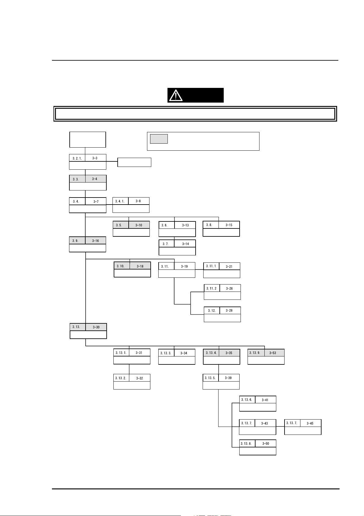
3.2 Disassembly and Assembly Procedures
This section describes disassembly or assembly procedures for pr inter assemblies and parts.
CAUTION
Read precautions in Section 3.1.1 prior to disassembly and assembly.
Start
Pre-disassembling
Operation
C202MAIN Board
Removal
Upper Housing Removal
C202PSB/PSE Board
Removal
Paper Supprt Removal
Stacker Removal
Control Panal Removal
Print Head Removal
Carriage Motor Removal
: If the shaded parts was replaced or removed,
perform the required adjustment which is mentioned
on page 4-1 of the Chapter 4
Paper Eject Frame
Assembly Removal
Paper Guide (Front)
Removal
ASF Assembly Removal
Home Position Sensor
Removal
ASF Assembly
Disassembly
ASF Home Position
Removal
Sensor
Rev. A
Printer Mechanism
Removal
Paper Feed Motor
Removal
Cap Assembly Removal
Pump Assembly Removal
Pump Motor Removal
Carriage Assembly
Removal
Top Frame Removal
Figure 3-1. Printer Disassembly Procedures
Ink Drain Pad Removal
Paper Empty Sensor
Assembly Removal
I/S Frame Removal
Paper Feed Roller
Assembly Removal
I/S Frame Disassembly
3-
Page 5
EPSON Stylus
4
&2/25
800
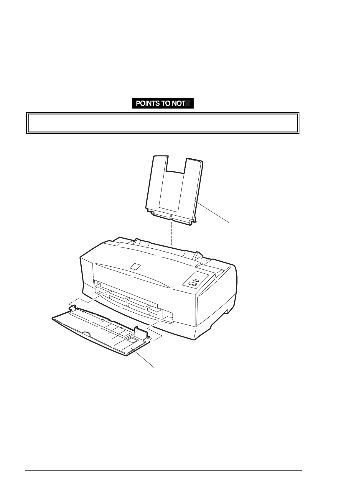
3.2.1 Before Beginning Disassembly
Remove the following parts before beg inning disassembly.
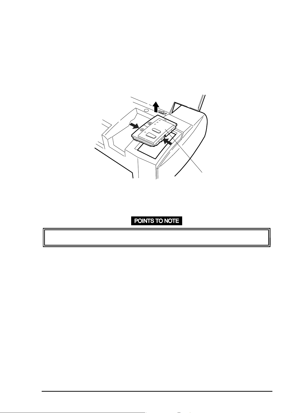
Paper Support
Output Tray
To remove the output tray, shift it to the right end, then push the handle on the left edge
inward. This will help you to remo ve it m or e easily.
2. Output Tray
Figure 3-2. Before Beginning Disassembly
1. Paper Support
3-
Rev. A
Page 6
Disassembly and Assembly
5
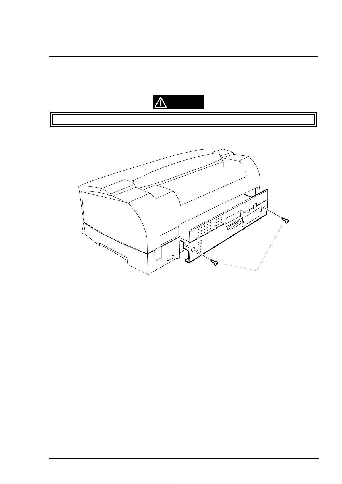
3.3 C202 MAIN Board Assembly Removal
1. Remove 2 screws (CBS, 3x8, F/Zn) securing the C202 MAIN board assembly to the back of
the printer. (See Figure 3-3.)
2. Move C202 MAIN board about 5 cm (2”) out from the back of the printer. (See Figure 3-3.)
CAUTION
C202 MAIN board assembly shield plate edges are sharp. So, be caref ul handling t hem.
CBS Scrws (3X8, F/Zn)
Figure 3-3. C202 MAIN Board Assembly Removal
Rev. A
3-
Page 7
EPSON Stylus
6
&2/25
800
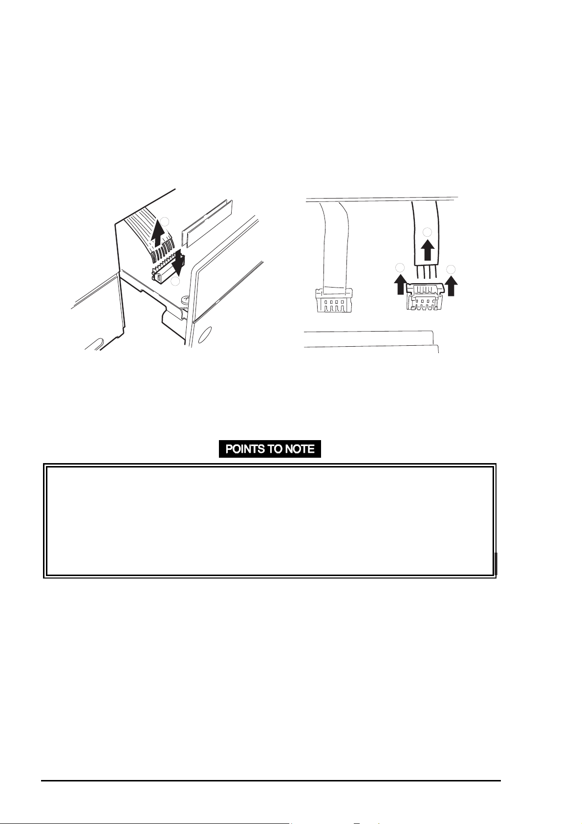
3. Disconnect all cables (CN4, CN6, CN7, CN8, CN11, CN12, and CN13) and FFCs (CN9 and
CN10) from C202 MAIN board assembly. (See Figure 3-4) Use instructions below to
disconnect connectors:
CN11, CN12, CN13: Release the connector lock lever by pulling it up, and
disconnect the cable.
CN4: Release the connector lock lever by pressing it down, and
disconnect the cable.
2
2
1
Disconnecting CN4
1
Disconnecting CN11, CN12, CN13
1
Figure 3-4. Connector Removal
Remove C202 MAIN board from the printer main board slot . (See Figure 3-3.)
❏ Note the direction when connecting cables for CN11, CN12, CN13, and CN4. Be sure to
insert the pin 1 side into the position marked w it h a “ 1” on the board.
❏ Ensure that the locks for CN11, CN12, CN13 are locked after connection.
❏ Hold down the lock lever for CN4 while connecting the cable.
❏ Make sure no cables or FFCs are cut by the shield plates.
❏ Tightening torque for the screws (CBS, 3X8, F/ Zn) is 8 ~10 kg- c m .
3-
Rev. A
Page 8
Disassembly and Assembly
7
3.4 Upper Housing Removal
1. Remove the parts shown in Figure 3-2.
2. remove 2 screws (CBS, 3X8, F/Zn) securing the C202 MAIN board assembly to the printer.
Then draw the C202 MAIN board forward about 5 cm.
3. Disconnect the control panel FFC from CN5 on the C202 MAIN board assembly.
(See Figure 3-5.)
Connector CN5
Figure 3-5 Connector for CN5 Removal
Rev. A
3-
Page 9
EPSON Stylus
8
&2/25
800
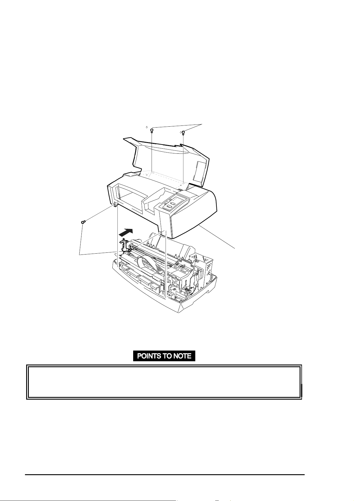
4. Remove 4 screws (CCP, 4x12, F/Zn): 2 screws securing the upper housing to the f ront and
2 screws securing the upper housing to the top rear side of the printer.
(Refer to Figure 3-6. )
5. Set the platen g ap lever to the “+” position. Then, pull the front part of the upper housing
forward, and lift it backward to remove.
CCP, 4X12
Upper Case
CCP, 4X12
Figure 3-6. Upper Housing Removal
❏ Before installing the upper housing, set the platen gap lever to the “+” position to make
the job easier. You must set it back to “0” after theu upper housing is securely positioned.
❏ Tightening torque for the screws (CCP, 4x12, F/Zn) = 10 kg-cm.
3-
Rev. A
Page 10
Disassembly and Assembly
9
3.4.1 C202 Panel Board Assembly Removal
1. Remove the upper housing. (See Section 3.4. )
2. Turn the upper housing up, and release the lock lever f or the FFC connector by pushing it
out. Then disconnect the FFC.
3. Release 2 hooks attaching the C202 panel board assembly to the upper housing. Then
remove the C202 panel board assembly from the upper housing. (See Figure 3-7.)
Control Panel
Figure 3-7. Control Panel Removal
❏ During assembly, be careful not to bend the contact plate m ount ed on the C202 panel
board.
Rev. A
3-
Page 11
EPSON Stylus
0
&2/25
800
3.5 Printhead Removal
1. Remove the upper housing. (Refer to Section 3.4.)
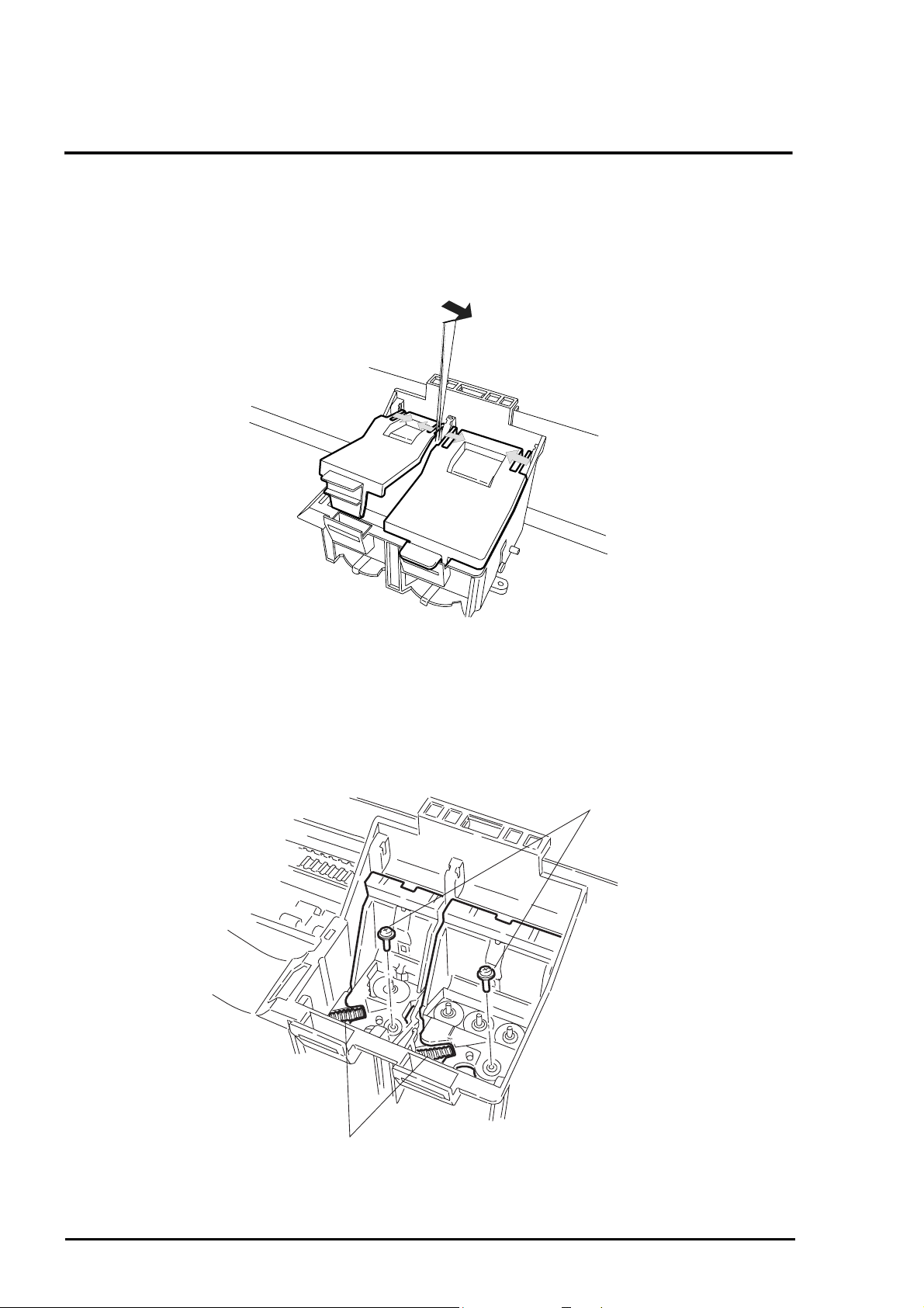
2. Open the ink cartridg e covers and r em ove the ink cartridges from t he CR assem bly.
3. Using tweezers, release the ink cartridge covers from the pins fixing them to the CR
assembly. Then remove the ink cartridge covers. ( See Figure 3-8.)
Figure 3-8. Cartridge Cover Removal
4. Remove 2 head fixing screws securing the printheads to the CR assembly at the bottom.
5. Remove 2 compression springs (9.9 g) holding each printhead t o the carriag e. (See Figur e
3-9.)
Head Fixing Screw
Compression Spring (9.9)
Figure 3-9. Screw and Spring Removal
3-1
Rev. A
Page 12
6. Remove 2 FFCs from the printheads. ( See Figure 3-10.)
Head FFCs
Disassembly and Assembly
Figure 3-10. Head FFC Removal
7. Shift the printheads forward. Then remove them by lif t ing upward carefully.
CAUTION
❏ In handling the printheads, note the follow ing:
Ground yourself. The driver IC is att ached dir ectly to the printhead unit.
Do not touch the printhead surface.
❏ Before installing a new printhead in the CR assembly, note the voltage ID stamped on
the right side of the printhead.
❏ When tightening and loosening printhead fixing screws, use your hand t o support the
bottom of the CR assembly.
Rev. A
3-11
Page 13
EPSON Stylus
2
&2/25
800
❏ Before installing the printhead into the CR assembly, move the carriage to the capping
position to protect the head surface.
❏ Procedures for printhead assembly are described below.
1. Remove the 2 FFCs from the clips used to att ach t hem .
2. Insert the color head FFC through the slit in t he back of the CR assembly with the
exposed terminal facing the rear, and connect it to the color head. Then install the
color head in the CR assembly.
3. Insert the black head in the CR assembly. Then insert the black head FFC through
the slit with the exposed terminal facing t he r ear.
4. Fasten the printheads in the CR assembly with the compression springs (9.9 g)
and head fixing screws.
5. Place both FFCs back into the clips used to hold them. Be sure t hey ar e also
placed in the small clip beside the larger one. Be careful not to disconnect the
FFCs from the printheads while installing t hem int o the clips. (See Figure 3-11.)
❏ Tightening torque for the head fixing screw = 2.5 ~ 3.1 kg-cm.
❏ When mounting a head fixing screw, screw carefully with force while supporting the
bottom of the carriage so not to st rip the screw head.
❏ Ensure the head fixing screw washers do not tur n after tightening head fixing screws.
FFC Fixing Clip
Head FFC
Figure 3-11. Head FFC and FFC Clips
REQUIRED ADJUSTMENT
❏ After replacing or removing the print head, perform the specified adjustment. ( See
Chapter 4.)
3-1
Rev. A
Page 14
Disassembly and Assembly
3
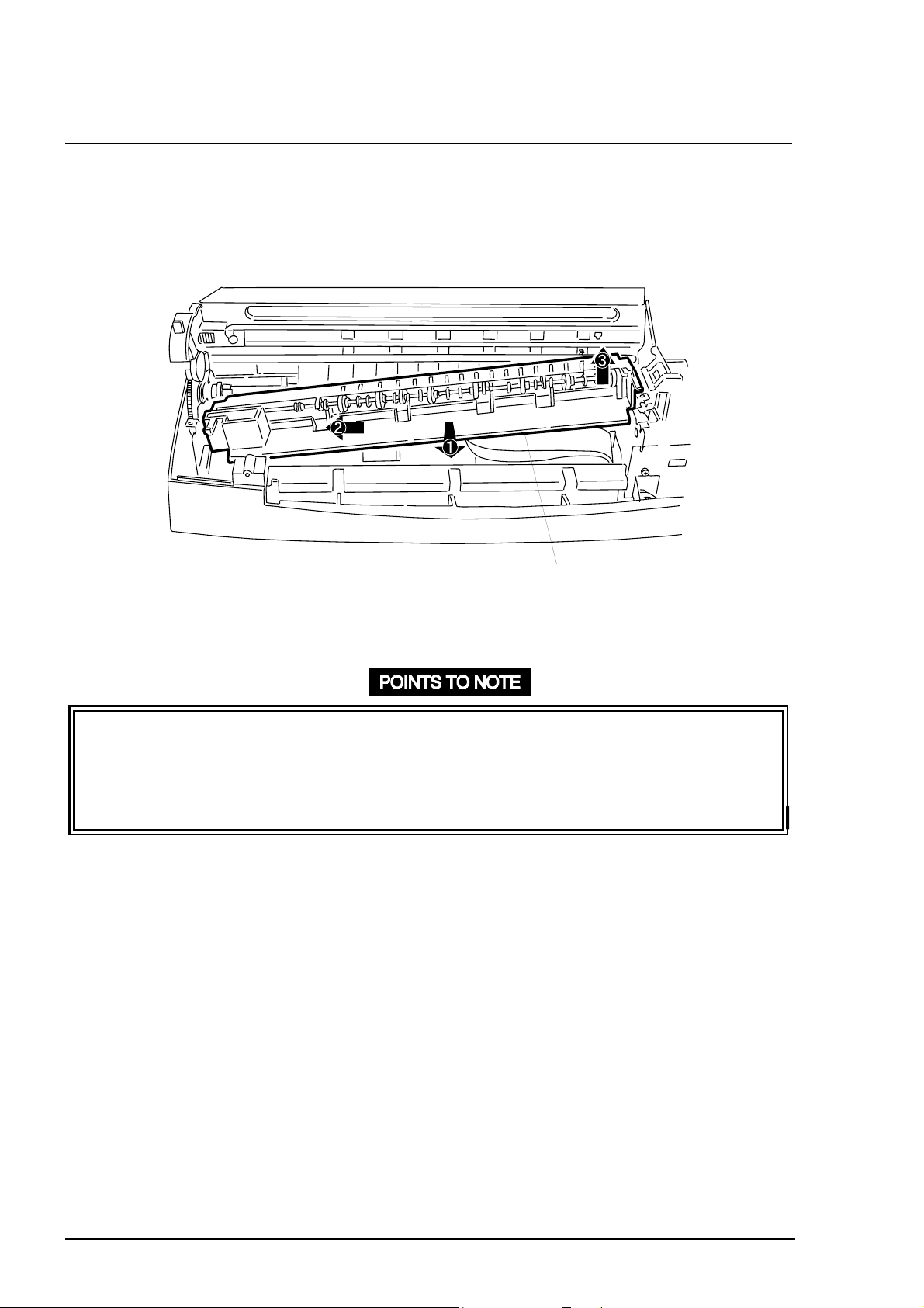
3.6 Paper Eject Frame Assembly Removal
1. Remove the upper housing. (See Section 3.4. )
2. Release the CR lock lever using tweezers. Then shift the CR to the left of the FFC holder.
3. Release 2 hooks for the FFC holder, and remove the FFC holder. (See Figure 3-12.)
FFC Holder
Paper Eject Frame
Figure 3-12. FFC Holder Removal
4. Remove the printhead FFCs from the sub holder, and remove the sub holder. Then remove
2 screws (CBS, 3x6, F/Zn) securing the paper eject frame. (See Figure 3-13.)
Paper Eject Frame CBS Screw (3X&, F/Zn) Head FFC
Figure 3-13. Screws Securing t he Paper Eject Frame
5. Hold down FFC along the paper eject frame, and shift the CR back to the capping position.
Then lift the paper eject frame assembly up about 3 mm (0.12”) and slide it forward.
❏ In mounting FFCs, be careful not to damage or catch them while sliding the CR unit.
❏ Make sure the FFC holder is securely hooked to the paper eject fr am e assembly.
❏ Tightening torque for the screws (CBS, 3x6, F/Zn) = 8 ~ 10 kg-cm .
Rev. A
3-1
Page 15
EPSON Stylus
4
&2/25
800
3.7 Front Paper Guide Assembly Removal
1. Remove the paper eject fram e assem bly. (See Section 3.6.)
2. Lift up the front paper guide assembly slightly, and shift it forward while sliding it t o the left
to release the pins from the cut out s in the right frame. (See Figure 3-14.)
Front Paper Guide Assembly
Figure 3-14. Front Paper Guide Removal
❏ There are 4 pins, 2 on each edge. Be sure to fit them int o the cutouts in the right and left
frame when installing the front paper guide assem bly.
❏ When engaging the gear (19 mm) on the left edge of the front paper guide assembly
and the gear (17 mm) on the left edge of the paper feed roller, be careful not to damage
them.
3-1
Rev. A
Page 16
Disassembly and Assembly
5
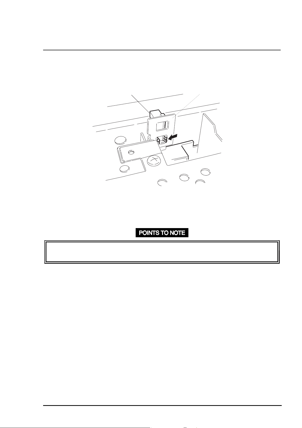
3.8 Home Position (HP) Sensor Removal
1. Remove the upper housing. (See Section 3.4. )
2. Using tweezers, release 2 hooks fixing the HP sensor to t he sub pum p f r ame. T hen rem ove
the HP sensor by pulling it downward. (See Figure 3-15.)
Home Postion Sensor
Figure 3-15. HP Sensor Removal
3. Disconnect the HP sensor connector cable from the HP sensor.
Sub Pump Frame
❏ Note the direction in which the HP sensor is att ached. Place t he cable side down.
❏ Tightening torque for the screws (CBS, 3x8, F/Zn) = 8 ~ 10 kg-cm .
Rev. A
3-1
Page 17
EPSON Stylus
6
&2/25
800
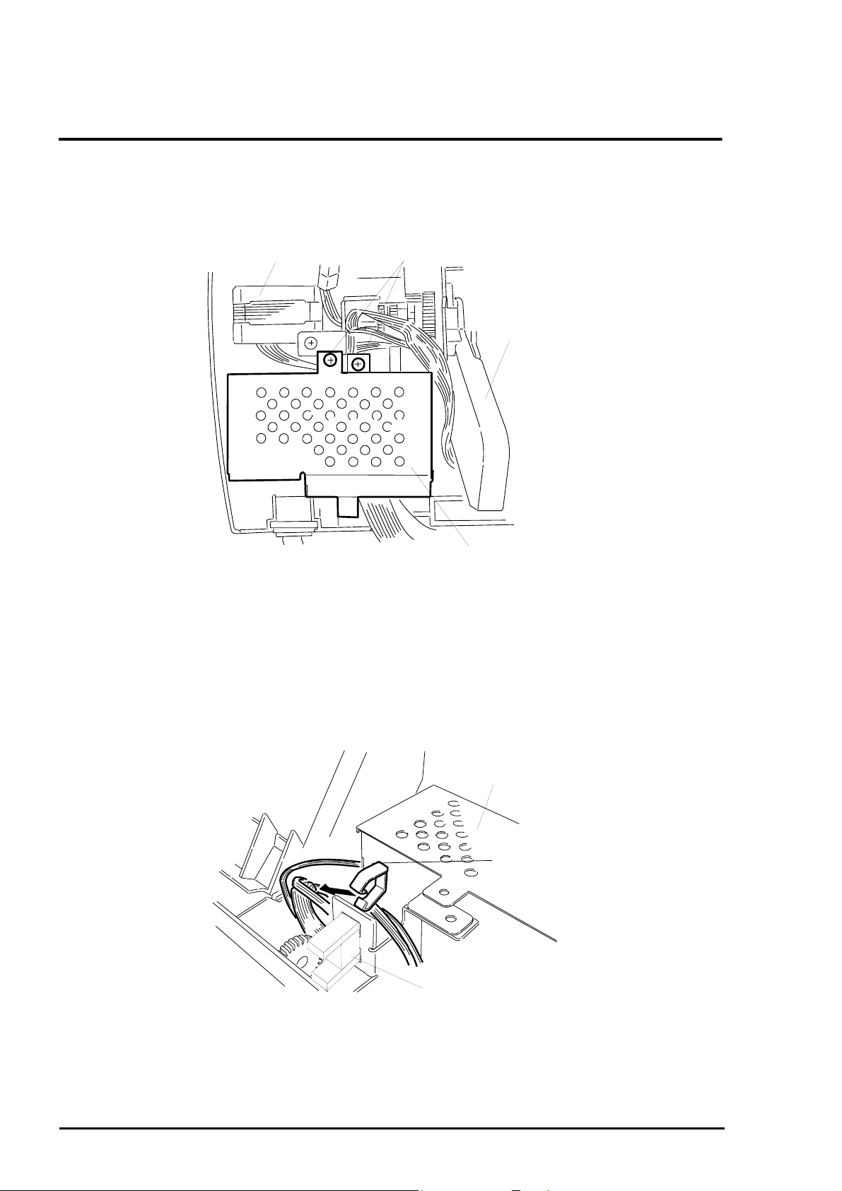
3.9 C202 PSB/PSE Board Assembly Removal
1. Remove the upper housing. (See Section 3.4. )
2. Remove 2 screws (CBS, 3x6, F/Zn) securing the C202 PSB/PSE board assembly to the
printer mechanism. (See Figure 3- 16.)
Carriage Motor
CBS Screw (3X6, F/Zn)
ASF Frame
C202PSB/PSE Board Assembly
Figure 3-16. C202 PSB/PSE Board Removal
3. Hold down the lock lever for CN4 on the C202 MAIN board assembly, and disconnect the
connector cable for the C202 PSB/PSE board.
4. Remove all connectors from the clamp attached to the C202 PSB/PSE board assembly.
(See Figure 3-17.)
C202 PSB/PSE Board
Assembly
Cable Clump
Home Position Sensor
Figure 3-17. Connector Cable Removal
5. Lift up the C202 PSB/PSE board, and remove it from the printer mechanism.
3-1
Rev. A
Page 18

Disassembly and Assembly
7
❏ Place the connectors for the printer m echanism back in the cable clamp after installing
the C202 PSB/PSE board assembly.
❏ Tightening torque for the screws (CBS, 3X6, F/ Zn) = 8 ~ 10 kg- c m .
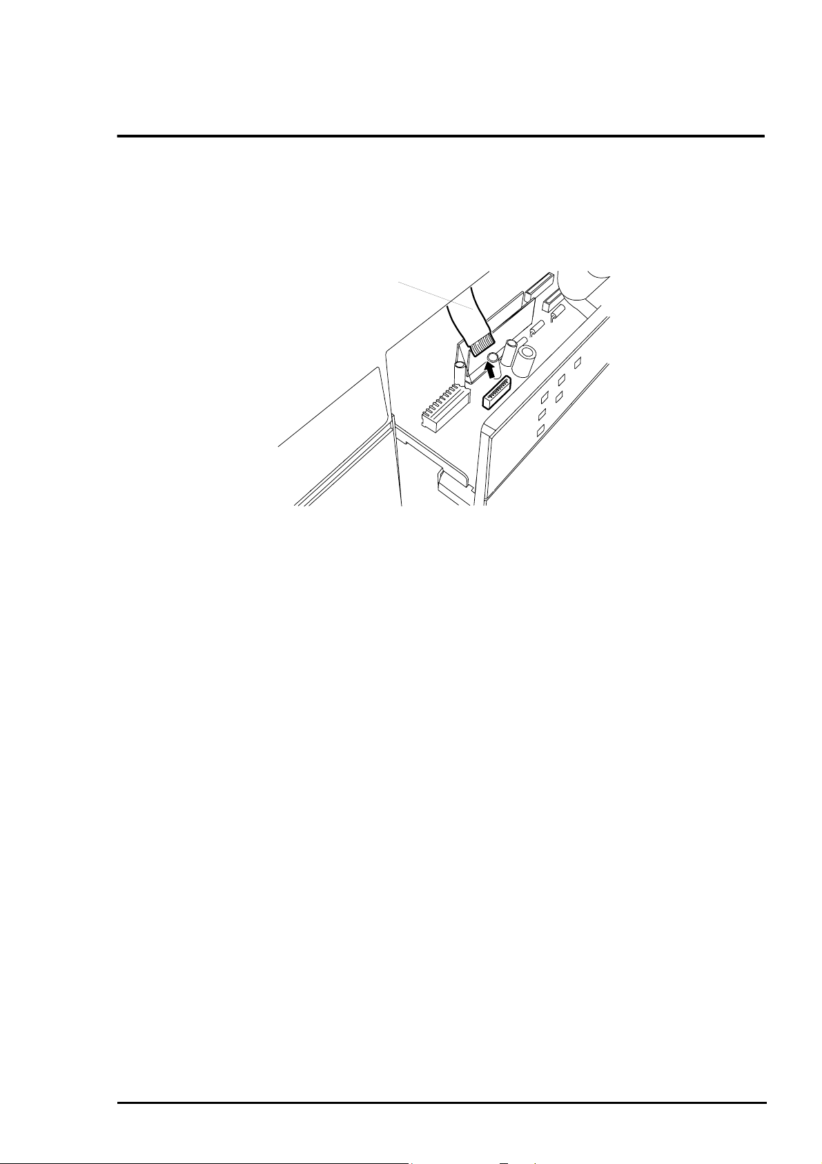
❏ When connecting the cable for the C202 PSB/PSE board to CN4 on the C202 MAIN
board, insert the cable through the slot , as shown in Figure 3-18.
C202PSB/PSE Board Assembly
CN4 Cable
Slit in the Lower Case
Figure 3-18. Removal of Cable for CN4
Rev. A
3-1
Page 19

EPSON Stylus
8
&2/25
800
3.10 Carriage Motor (CR Motor) Assembly Removal
1. Remove the upper housing. (See Section 3.4. )
2. Release the CR lock lever using t weezers. Then shift t he CR assembly from the capping
position manually.
3. Remove 2 screws (CBS, 3x6, F/Zn) securing the CR motor assembly to t he t op frame. (See
Figure 3-19.)
Timing Belt
Figure 3-19. Screws Securing t he CR M otor Assembly
Top Frame
CBS Screws (3X6, F/Zn)
4. Disengage the timing belt from the pinion gear.
5. Unlock CN12 on the C202 MAIN board by pulling up the lock lever. Then disconnect the CR
motor connector cable from CN12.
6. Remove the CR motor assembly from the printer mechanism.
❏ When mounting the CR motor assembly t o the top frame, insert the CR mot or cable
facing the bottom of the print er, and fit the CR motor assembly pins into the cutout in the
top frame.
❏ Tightening torque for the screws (CBS, 3x6, F/Zn) = 8 ~ 10 kg-cm .
REQUIRED ADJUSTMENT
Perform the Bi-d adjustm ent after reinstalling the CR motor assembly. See Chapter 4.
3-1
Rev. A
Page 20

Disassembly and Assembly
9
3.11 ASF (Auto Sheet Feeder) Removal
1. Remove the C202 PSB/PSE board assembly. (See Section 3.4.6.)
2. Remove 2 screws (CPS, 4x10 and ASF fixing screw, F/Zn) securing the ASF to the right
frame and to the rear left of the frame, respectively. ( See Figure 3-20.)
ASF Fixing Screw
CBP Scrwe (4X10, F/Zn)
Figure 3-20. Removal of Screws Fixi ng t he ASF
3. Remove 1 gear (27.2 mm) at the right edge of the ASF from the hopper release lever by
squeezing with tweezers or prying a Phillips screwdriver into the joint. (See Figure 3- 21. )
Tweezers
Gear (27.2)
Figure 3-21. Gear (27.2 mm) Removal
Rev. A
3-1
Page 21

EPSON Stylus
0
4. Slide the ASF assembly to the left, then to the rear; and remove the ASF assembly from the
printer mechanism. Be sure to disconnect t he ASF HP sensor cable from the sensor.
&2/25
800
❏ Connect the ASF HP cable to the connector at the lef t edge of the ASF before installing
the ASF assembly.
❏ Several connectors are laid behind the ASF assembly. Make sure they are not cut under
the ASF assembly when installing the ASF.
❏ Tightening torque for the screws (CBP, 4x10, F/Zn) = 10 ~ 12 kg- cm .
❏ When engaging the gear (27.2 mm) and loading (LD) roller shaft, note the side they
face. Make sure they are correctly adjusted and securely locked. (See Figure 3-22.)
Loading Roller Shaft
Release Hopper Lever
Figure 3-22. Engagement of Loading Roller Shaft and Gear (27.2 mm)
Gear (27.2)
3-2
Rev. A
Page 22

Disassembly and Assembly
3.11.1 ASF Assembly Disassembly
1. Remove the ASF. (See Sect ion 3.11. )
2. Remove the left shaft bushing, located at the left end of the loading ( LD) roller shaft. (See
Figure 3-23.)
Bushing Fixing the Shaft
on the Left
Loading Roller Shaft
Figure 3-23. Left Bushing Removal
CAUTION
Remove this bushing with care so you do not damage it.
3. Shift the LD roller shaft about 1 cm (half an inch) left, and using tweezers, and release the
tab attaching the detection wheel to the left edge of the LD roller shaft. Then remove the
detection wheel. (See Figure 3-24.)
Rev. A
Detection Wheel
Figure 3-24. Detection Wheel Removal
Loading Roller Shaft
3-21
Page 23

EPSON Stylus
2
&2/25
800
4. Release the pin at the top left edge of t he hopper assembly f rom the ASF f r ame. Then alig n
the right arm of t he hopper assembly with the cutout in the ASF right frame, and rem ove the
hopper assembly carefully by lifting up the left edge. Be careful not to bend the
compression springs in the paper loading assemblies. ( See Figure 3-25.)
Hopper Assembly
ASF Frame
Top Left Part of ASF Assembly
Bottm Right Part of ASF Assembly
Arm
Cutout in the ASF Frame
(Bottom right)
Figure 3-25. ASF Hopper Assembly Removal
5. Shift the LD roller shaft further left , and r emove the paper loading assem blies along with the
paper loading shaft fr om the ASF frame.
6. Remove the paper loading assemblies from the LD roller shaft.
7. Release 2 hooks securing the LD roller cover to the paper loading assembly using the
tweezers. Then remove the LD roller cover. (See Figure 3-26.)
Paper Takup Roller
Assembly
Paper Takeup
Roller Cover
Locking Tabs
Figure 3-26. LD Roller Cover Removal
8. Release 2 locking tabs securing t he LD r oller assem bly to the paper loading assembly using
the tweezers. Then remove the LD roller assembly. (See Figure 3-27).
3-2
Rev. A
Page 24

3
Paper Takeup Assembly
Paper Takeup Roller Assembly
Fixing Clicks
Figure 3-27. Locking Tabs on the LD Roller
CAUTION
Disassembly and Assembly
Never touch the rubber part of the LD roller assemblies with your bare hands.
❏ Ensure the following are correctly mount ed ont o the paper loading assembly before
assembling. (See Figure 3-28.)
1 torsion spring
1 extension spring 1 compression spring rod spring
❏ When installing paper loading assemblies, insert the LD r oller’s narrow edge to the left.
Extension Spring
Rod Spring
Paper Loading Assembly
Compression Spring (1.66)
Tosrion Spring
Figure 3-28 Spring Installation
Rev. A
3-2
Page 25

EPSON Stylus
4
&2/25
800
❏ Follow the instructions below when installing t he hopper assem bly into the ASF frame
with the paper loading assemblies mounted on it: (See Figure 3- 29. )
1. Note the direction to place the compression spring. One end is bent straight
inward. Be sure to insert the st r aight end facing up.
2. Hook the straight end to the fram e as show n in Figur e 3-29.
3. Insert tweezers through the cutout in the back of the ASF frame to release the
tabs after mounting the hopper assembly. (See Figure 3-29.)
❏ When installing the LD roller shaft into the ASF frame after mounting both paper loading
assemblies, shift the right paper loading assembly t o the right edge of the ASF frame,
then fix it by aligning the grroove in the back of the paper loading assembly, however,
moves freely from left to right or vice versa. (See Figure 3-30)
ASF Frame
Paper Loading Assembly
Figure 3-30 Paper Loading Roller Install at i on
Compression Spring (1.66)
Hooks
ASF Frame Rail Ribs
Roung cutout at the back of the
ASF Frame
Straight End of the Compresion Spring (1.66)
Figure 3-29. Releasing the Compression Spring
3-2
Rev. A
Page 26

Disassembly and Assembly
5
g
❏ Be sure to fix both right and left pins on the ASF fr ame securely into the holes in the
hopper assembly.
❏ When installing the detection wheel onto the left end of the LD roller shaft, be sure to
engage it in the right direction. Pay attention to which way the end faces.
❏ Ensure that the left frame of the left paper loading assembly fits correctly into the groove
in the bottom of the left edge guide f or the hopper assembly. (See Figure 3-31.)
Left Edge Guide of the Hopper Assembly
Bushing
Left Frame of the Left Paper Loading Assembly
Figure 3-31. Engaging Hopper Assembly and Bushin
Rev. A
3-2
Page 27

EPSON Stylus
6
&2/25
800
3.11.2 ASF HP Sensor Removal
1. Remove the ASF assembly. (Refer to Section 3.11.)
2. Remove the right hopper release lever in the ASF assembly.
3. Remove the bushing from the left edge of the loading (LD) roller shaf t in the ASF assem bly.
(See Figure 3-32.)
Bushing Fixing the Shaft at the Left
Paper Loading Roller Shaft
Figure 3-32. Bushing Removal
4. Shift the LD roller shaft lef t about 2 cm ( 1”) . T hen, using tweezers, release the t ab f ixing the
detection wheel at the left edge of t he LD roller shaft. (See Figure 3-33. )
Detection Lever
Figure 3-33. Detection Wheel Removal
3-2
Paper Takeup Roller Shaft
Rev. A
Page 28

Disassembly and Assembly
7
5. I nsert tweezers into the slit in the back of the ASF HP sensor, and release the clips. Then
remove the ASF HP sensor. (See Figure 3-34.)
ASF Frame (Left Side)
ASF Home Position Sensor
Tweezers
Figure 3-34. ASF HP Sensor Removal
❏ When mounting the detection wheel onto the LD roller shaft, push the wheel into the
shaft until it clicks.
❏ The bushing at left end of the LD roller shaft m ust be located on the right of the left
hopper release lever. (See Figure 3-32.)
Rev. A
3-2
Page 29

EPSON Stylus
8
&2/25
800
3.12 Paper Feed (PF) Motor Assembly Removal
1. Remove the ASF. (Refer to Section 3.11.)
2. Remove 1 C-ring and 1 plain washer securing the combination gear (14 mm, 31.5 mm) to
the left frame.
3. Remove 2 screws (CBS, 3x6, F/Zn) securing the PF motor assembly to the left frame.
(Refer to Figure 3-35. )
CBS Screws (3X6, F/Zn)
Combination Gears (14, 31.5)
Figure 3-35. PF Motor Assembly Removal (1)
4. Push the PF motor assembly inward, holding the combination gears, and remove the PF
motor assembly and the combination gears. (Refer to Figure 3-36.)
C-ring
Paper Feed Motor Assembly
Plain Waher
Left Frame
Figure 3-36. PF Motor Assembly Removal (2)
3-2
Combination Gears (14, 31.5)
Rev. A
Page 30

Disassembly and Assembly
9
5. Disconnect the paper feed motor cable from the CN13 on the C202 MAIN board assembly.
6. Remove the PF motor from t he pr inter mechansm.
❏ Be careful not to damage the teeth on the combination gear (14 mm, 31.5 mm), paper
feed pinion gear, or gear (70 mm) when engaging them.
❏ When installing the PF motor assembly in t he lef t frame, be sure to fit the shaft for the
combination gear into the cutout in the f r am e.
❏ Tightening torque for the screws (CBS, 3X8, F/ Zn) = 8 ~ 10 kg- c m .
Rev. A
3-2
Page 31

EPSON Stylus
0
&2/25
800
3.13 Printer Mechanism Removal
1. Remove the units and assemblies by following the procedures described in Sect ion 3. 9.
2. Disconnect all the connectors and FFCs fr om t he C202 MAIN board assembly.
3. Remove 4 screws (CB, 4x12, F/Zn) securing the printer mechanism to the lower case.
(Refer to Figure 3-37. )
CB Screws (4X12, F/Zn)
CB Screws (4X12, F/Zn)
Figure 3-37. Printer Mechanism Screw Removal
4. Lift up the printer mechanism to remove it from the lower case.
❏ Make sure the connectors are not cut when you inst all t he pr inter mechanism.
❏ Always hold the upper or rear part of t he mechanism, and never touch the gears.
❏ Do not forget to insert the sub ink drain pad into the printer mechanism before installing
the mechanism into the lower case. The m ount ing locat ion is show n in Figure 3-38.
❏ Tightening torque for the screws (CB, 4x12, F/Zn) = 4 ~ 5 kg-cm .
3-3
Rev. A
Page 32

Sub Drain Ink Pad
Printer Mechanism Viewed from the Rear
Figure 3-38. Sub Ink Drain Pad
Disassembly and Assembly
REQUIRED ADJUSTMENT
❏ Perform necessary adjustm ent and data input referring to Table 4-1 in Chapter 4 when
the printer mechanism is replace with a new one.
3.13.1 Cap Assembly Removal
1. Remove the printer mechanism. (Refer to Section 3.13.)
Black Ink Tube
Color Ink Tube
CBS Screw (3X6)
Figure 3-39. Tube Removal
2. Release the CR lock lever using tweezers, and slide the CR assem bly left.
3. Remove 1 screw (CBS, 3x6, F/Zn) securing the cap assembly to the top frame.
4. Remove both tubes from the black and color caps carefully. (See Figure 3-39.)
5. Remove the cap assembly from the printer mechanism.
Rev. A
3-31
Page 33

EPSON Stylus
2
&2/25
800
❏ Tubes linking the pump assembly are made of silicone, and a minor flaw can become a
crack. Therefore, use the exclusive tw eezers designed for the tubes car efully when
positioning the tubes back onto the pins.
❏ Handle the cap assembly carefully, and never touch the rubber portion and pad portion
of the caps.
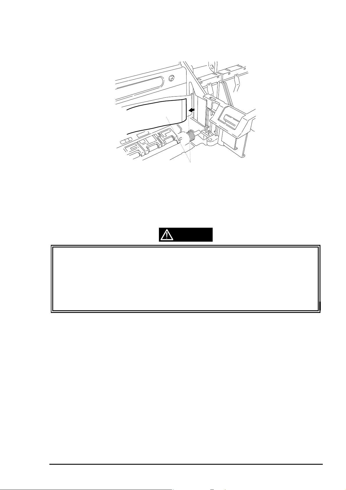
❏ Align the pin at the left edge with the hole in the right frame when positioning the cap
assembly, as show in Figure 3-40.
❏ Make sure that the right edge of the cap assembly is locat ed on t he right of the left edge
of the top frame.
❏ Tightening torque for the screws (CBS, 3x6, F/Zn) = 8 ~ 10 kg-cm .
Right Frame
Cap Assembly Location Holes
Figure 3-40. Cap Assembly Removal
Cap Assembly
3-3
Rev. A
Page 34

Disassembly and Assembly
3
3.13.2 Pump Assembly Removal
1. Remove the cap assembly. (Refer to Section 3.13.1. )
2. Remove 2 screws (CBS, 3x6, F/Zn) securing the outer sub frame assembly to the middle
sub frame assembly and to the slider shaf t respectively. Then remove the whole outer sub
frame assembly with the pump drive gear and the pump reduction gear. (Refer to Figure 3-
41.)
Middle Sub Frame Assembly
Figure 3-41. Outer Sub Frame Assembly Removal
CBS Screws (3X6, F/Zn)
Outer Sub Frame
Rev. A
3-3
Page 35

EPSON Stylus
4
3. Remove 1 screw (CBS, 3X6, F/Zn) secur ing the pump assembly to the middle sub frame
assembly. (Refer to Figure 3-42.)
&2/25
800
Pump Assembly
CBS Scew (3X6, F/Zn)
Middle Sub Frame Assembly
Figure 3-42. Pump Assembly Removal
4. Remove the pump assembly from the middle sub frame assembly.
CAUTION
❏ Be careful not to damage the tubes while removing the pump assembly.
❏ Tightening torque for the screws (CBS, 3x6, F/Zn) = 8 ~ 10 kg-cm .
❏ Never install the pump assembly into the printer mechanism before mounting the head
cleaner on the pump assembly. The head cleaner must not be mounted on the pump
assembly alone.
❏ When mounting the head cleaner on the pump assembly, face the rubber part of the
cleaner to the right. Be sure to hook the hole in t he head cleaner to the pump assembly,
as shown in Figure 3-43.
3-3
Rev. A
Page 36

5
Pump Assembly
Pump Assembly Viewed from the Right
Figure 3-43. Head Cleaner Location
3.13.3 Pump Motor Removal
Disassembly and Assembly
Hook Fixing the Head Cleaner
1. Remove the printer mechanism. (Refer to Section 3.13.)
2. Remove 2 screws (CBS, 3x6, F/Zn) securing the pump motor to t he pump sub fram e. Then
remove the pump motor. (Refer to Figure 3-44.)
Pump Motor
CBS screw (3X6, F/Zn)
Printer Mechanism Viewed from the Right
Figure 3-44. Screws Fixi ng t he Pump M ot or
❏ Be careful not to damage the combination gear (12 mm, 26 mm) when mounting the
pump motor pinion gear into the motor pinion gear mounting hole in the pump sub frame.
❏ When installing the pump motor onto the pump sub frame, insert the motor harness
facing the top.
❏ Tightening torque for the screws (CBS, 3x6, F/Zn) = 8 ~ 10 kg-cm .
Rev. A
3-3
Page 37

EPSON Stylus
6
&2/25
800
3.13.4 Carriage (CR) Assembly Removal
1. Remove the printer mechanism. (Refer to Section 3.13.)
2. Release the CR lock lever using tweezers. Then manually slide the CR assembly from the
capping position.
3. Remove 2 screws (CBS, 3x6, F/Zn) securing the CR motor assembly to the printer
mechanism top frame.
4. Disengage the timing belt from the pinion gear in the CR motor assembly. (See Figure
3-45.)
Timing Belt
Figure 3-45. Timing Belt Removal
5. Remove the printhead. (Refer to Section 3.5.)
Carriage Motor Pinion Gear
CAUTION
To prevent printhead damage, never disassemble or assemble the CR assembly with the
printhead installed in it.
3-3
Rev. A
Page 38

Disassembly and Assembly
7
6. Remove 1 E-ring and 1 screw (CBS, 3x6, F/Zn) securing the right parallelism adjustment
bushing to the top fram e. Then tur n the bushing f orward unt il it fit s into the cut out in the top
frame and slide it to the rig ht. (Refer to Figure 3-46. )
Top Frame
Right Parallelism Adjust Bushing
Figure 3-46. Parallelism Adjustment Bushing Removal
7. Remove the compression spring (19.9 g) using tweezers. Then shift the sub pulley holder to
the right and remove it fr om t he top frame. (Refer t o Figure 3-47.)
Compression Spring (19.9)
Sub Pulley Holder
Figure 3-47. Sub Pulley Holder Removal
Rev. A
3-3
Page 39

EPSON Stylus
8
8. Shift the CR shaft to t he rig ht t o re move the CR assem bly fr om t he platen g ap lever and lef t
parallelism adjustment bushing. ( See Figure 3-48.)
&2/25
800
Platen Gap Lever
Figure 3-48. CR Assembly Removal
9. Take the CR shaft out fr om the CR assembly.
10. Remove the oil pad from the CR assembly.
Carriage Assembly
❏ Place the oil pad with the oiled side down onto the CR guide w hen mounting the oil pad
into the CR assembly.
❏ Install the CR shaft with the edge whose side is cut in a “D” shape to the left.
❏ When installing the platen gap sub lever onto the CR shaft, insert the side marked with
an “{ “ out, set the platen gap lever to 0, and engage t he platen gap sub lever notch with
the platen gap lever by slipping it upward. (See Figure 3- 49.)
❏ When installing the CR assembly, make sure the timing belt has no torsion and is
correctly placed between the CR assembly and top f r am e.
❏ Fit the groove on the upper edge of the CR assembly to the top edge of the top frame.
(See Figure 3-49.)
❏ Fit the CR shaft into the U-cut of the slider. (See Figure 3-51.)
❏ To tur n t he r ight par allelism adjustment bushing to the rear, support it by the bottom and
push the top edge outward.
❏ When mounting the compression spring (19. 9 g) ont o the sub pulley holder, fit the spring
to the pin on the left end of the holder f ir st .
3-3
Rev. A
Page 40

9
Platen Gap Lever
Platen Gap Sub Lever
Figure 3-49. Engaging the PG Sub Lever
Disassembly and Assembly
Carriage Frame
Top Frame Edge
Viewed from the top
Figure 3-51. Fitting the Cartri dge Slider to the Upper Edge
Carriage
Slider
Slider Shaft
Carriage Shaft
Figure 3-50. Engaging the Cartridge Shaft and Sl ider Shaft
REQUIRED ADJUSTMENT
❏ In case that the CR assembly is replaced, per form necessary adjustment (Refer to Table
4-1 in Chapter 4)
Rev. A
3-3
Page 41

EPSON Stylus
0
&2/25
800
3.13.5 Top Frame Removal
1. Remove the ASF assembly. (See Section 3.11.)
2. Remove the printer mechanism. (See Sect ion 3. 13.)
3. Remove the CR assembly. (See Section 3.13.4.)
CAUTION
❏ It is possible to remove the top fram e without removing the CR assembly and ASF
assembly, but it is highly recommended that you remove these assemblies before
removing the top frame. Otherwise the printheads or frames might be dam aged or bent.
4. Using tweezers, remove torsion springs (117.6 g) attaching 5 upper paper guide assemblies
and 1 right paper guide assembly. Then, take the 5 upper paper guide assemblies out
backwards and the right paper guide assembly f or ward to r emove them. (See Figure 3-52.)
Torsion Spring (117.6)
Top Frame
Upper Paper Guide
Printer Mechanism Viewed from the Rear
Figure 3-52. Releasing the Torsion Springs
Rear Paper Guide
3-4
Rev. A
Page 42

Disassembly and Assembly
5. Remove 3 screws (CBS, 3x6, F/Zn) securing the top frame t o the printer mechanism, and 1
screw CBS, 3x6, F/Zn) securing the top fr am e and cap assem bly. (See Figure 3-53.)
CBS Screw (3X6, F/Zn)
Figure 3-53. Removing the Screws Securing t he Top Frame
6. Disconnect the paper end sensor connector cable from the paper end sensor assembly.
Then remove the top frame.
❏ In installing the top frame to the printer mechanism, be sure not to damage the gear
(70 mm) at the left edge
❏ Be sure to place the driven roller shafts in t he upper paper guide assemblies parallel to
the PF roller. Figure 3-54 shows how to engage upper paper guide assembly parts .
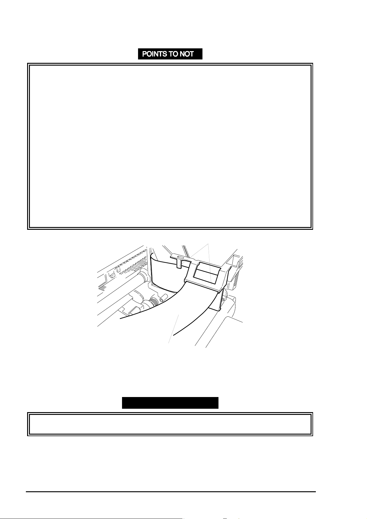
❏ When mounting the right paper guide assembly, insert it into the gap from the fr ont , as
shown in Figure 3-55.
❏ Tightening torque for the screws (CBS, 3x6, F/Zn) = 8 ~ 10 kg-cm
Rev. A
3-41
Page 43

EPSON Stylus
2
&2/25
800
Top Frame
Right Paper Guide Assembly
Printer Mechanism Viewed from the Front
Paper Feed Roller
Figure 3-55. Right Paper Guide Installation
3.13.6 Paper Empty (PE) Sensor Assembly Removal
1. Remove the top frame. ( Refer to 3.13.5.)
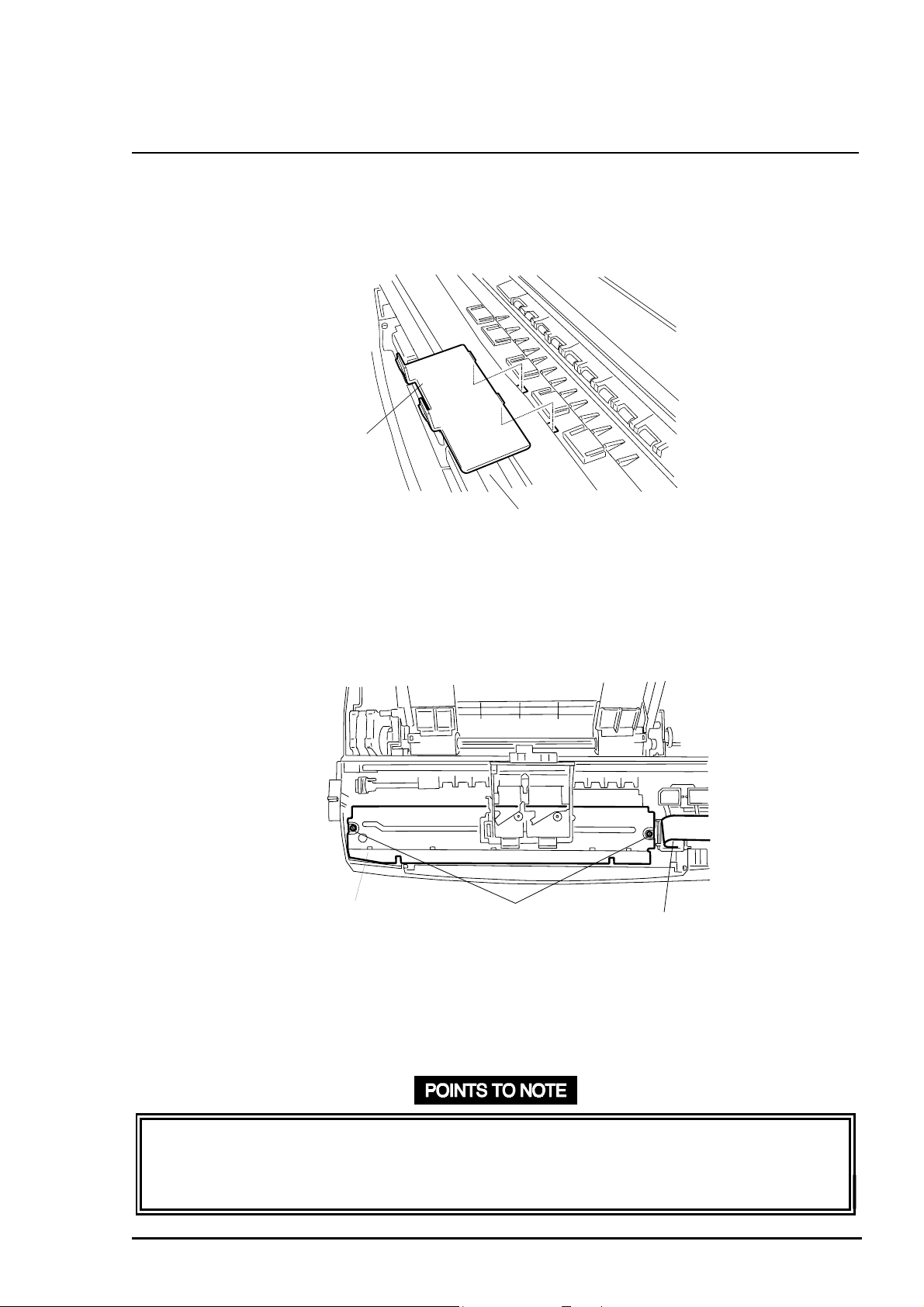
2. Release the hook for the PE sensor assembly using tweezers. Then remove the paper end
sensor assembly by lifting upward. (See Figure 3-56.)
Hooks Attaching the
Paper End Sensor
Top Frame
Location holes
Figure 3-54. Paper End Sensor Assembly Removal
3-4
Rev. A
Page 44

Disassembly and Assembly
3
❏ When mounting the paper end sensor assembly on the t op f rame, be sure to mount the
torsion spring correctly at the point shown in Figure 3-57.
❏ After installing the paper empty sensor lever, ensure it bounces smoothly.
❏ Install the paper empty sensor and right paper guide assem bly in t he following order:
c
Mount the paper empty sensor onto the t op f r am e.
d
Align the paper empty sensor lever with the cut out in the upper paper guide
assembly.
e
Attach the right paper guide assembly to the t op frame, or refer to POI NTS TO
NOTE in Section 3.13.5.
❏ Ensure that the hooks for the PE sensor assembly f it secur ely into the cutouts in the top
frame.
Printer Mechanism Viewed from the Bottom
Paper End Sensor
Cable Connector
Figure 3-56. Torsion Spring
Torsion Spring (0.22)
Rev. A
3-4
Page 45

EPSON Stylus
4
&2/25
800
3.13.7 I/S (Ink System) Frame Removal
CAUTION
When releasing joints linking the I/S frame and right frame, be careful not to bend the
frames.
1. Remove the pump assembly. (Refer to Section 3.13.2.)
2. Remove the top frame. ( Refer to Section 3.13.5.)
3. Remove the head FFCs from the sub cable holder. (See Figure 3-58.)
Head FFCs
Sub Cable Holder
Figure 3-57. Head FFC Removal
4. Remove 2 screws (CBS, 3x6, F/Zn) securing the I/S frame and right frame. (See Figure
3-59.)
CBS Screws (3X6, F/Zn)
I/S Frame
Figure 3-58. I/S Frame Removal (1)
3-4
Rev. A
Page 46

Disassembly and Assembly
5
5. Slide the I/S frame forward by releasing 3 joints (2 at the back and 1 on t he front of the
printer mechanism) for the I/S frame and right frame. Then remove the I/S frame by
lowering downward. (See Figure 3-60.)
Right Frame
Joints
I/S Frame
Figure 3-59. I/S Frame Removal (2)
6. Remove connector cables for the CR HP sensor and pump motor from the printer
mechanism.
Rev. A
3-4
Page 47

EPSON Stylus
6
&2/25
800
❏ When joining the I/S frame wit h t he r ight f rame, be sure to align it with the slots in t he
right frame appropriately. Then push until it meets resistance.
❏ Pay attention to the 20.8 mm gear in the combination gear (12 mm, 20.8 mm) when
connecting the I/S frame to the right fram e. It must engage the 16.8 mm gear cor rectly. ❏
❏ Leave some backlash for the combination gear (12 mm, 20.8 mm).
❏ When attaching the I/S fr am e t o the right frame, be sure to mount t he scr ew on the front
first. Otherwise, the frame will bend. (See Figure 3-61.)
❏ After installing the I/S fram e onto the printer mechanism, only carry t he pr int er
mechanism by holding the bottom frame.
❏ Tightening torque for the screws (CBS, 3x5, F/Zn) = 8 ~ 10 kg-cm .
1
Figure 3-60. Order for Mounting Screws
3-4
2
Rev. A
Page 48

Disassembly and Assembly
7
3.13.7.1 I/S Frame Disassembly (Removing the Pump Motor)
1. Remove the I/S frame. ( See Sect ion 3. 13.7.)
2. Remove 2 screws (CBS, 3x6, F/Zn) securing the pump motor. (See Figure 3-62.)
Pump Motor
CBS screw (3X6, F/Zn)
Printer Mechanism Viewed from the Right
Figure 3-61. Removing the Screws Securing t he Pump M ot or
3. Remove 1 hexagon nut (6N, class-2, M4) and 1 draft spring (0.4 g) securing the slider shaf t
to the middle sub frame. T hen r emove the slider shaft. (See Figure 3-63. )
Extension Spring
Gear (16.8)
Middle Sub Frame
Hexagon Nut (6N, Class-2, M4)
Shaft Slider
Figure 3-62. Slider Shaft Removal
CAUTION
Be careful not to damage the gear (16.8 mm) when removing the hexagon nut (6N, class-2,
M4) securing the slider shaft.
Rev. A
3-4
Page 49

EPSON Stylus
8
&2/25
800
4. Remove 1 hexagon nut (6N, class-2, M4) and 1 draft spr ing (0.4 g) securing the slider shaft
Remove 2 screws (CBS, 3x6, F/Zn) securing the inner sub frame. Then remove the inner
sub frame and following 6 parts from the middle sub frame:
c Combination gear (12 mm, 20.8 mm) d Gear (16.8 mm)
e Plain washer (7.2x0.3x12, S/Na) f Compression spring (0.26 g)
g Compression spring (0.31 g) h Plain washer (5.2x0.2x11, S/Na)
(See Figure 3-64.)
Inner Sub Frame
Plain Washer
7.2X0.3X12,S/Na
Compression Spring 0.26
CBS Screws 3X6,F/Zn
Figure 3-63. Inner Sub Frame Removal
Combination Gear
12,20.8
Gear 16.8
Compression
Spring 0.31
Inner Sub Frame
Compression
Spring
Be careful not to catch the
Compression Spring with
the Inner Sub Frame.
Plain Washer 5.2X0.2X10,S/Na
3-4
Rev. A
Page 50

Disassembly and Assembly
9
5. Remove 2 screws (CBS, 3X6, F/Zn) securing the middle sub frame, then remove the
middle sub frame and the following 11 parts from the sub pump frame:
c Combination gear (12, 15) d Plain washer (5.2x0.3x12, S/Na)
e Spring washer (5.3x0.07x10, S/Na) f Combination gear (14.4, 21.6)
g Cam h Torsion spring (7.3)
i Combination gears (12, 26) j Gear (11.5)
k 3 E-rings (4, F/UC)
(See Figure 3-65.)
Sub Middle Frame
Combination Gear,
14.4,21.6
Combination Gear,
21,26
Sub Middle Frame
CB Screw (3x6,F/Zn)
Torsion Spring, 7.3
Cam
Gear, 11.5
E-ring (4,F/UC)
Combination Gear, 12,15
Plain Washer
(5.3x0.3x12,S/Na)
U-type Spring Washer
(5.3x0.07x10, S/Na)
Figure 3-64. Middle Sub Frame Removal
U-type Spring Washer
Plain Washer
Combination Gear, 12,15
Pay attention to the assembly order
of above 3 parts.
CAUTION
❏ Do not mount the E-ring before engaging all fr am es. Otherwise frames and shafts may
bend. Be sure to use the exclusive E-ring holder to avoid damaging gear s and shaf ts.
❏ Notice how gears engage. See figures 3-64 and 3-65.
❏ Tightening torque for the screws (CBS, 3x6, F/Zn) = 8 ~ 10 kg-cm .
❏ After tightening screws, make sur e the U-shaped spring washer is mounted correctly.
Rev. A
3-4
Page 51

EPSON Stylus
0
&2/25
800
Checklist after Engaging I/S Frame
❏ Gear engagement
Insert the cam in the direction show n in Figur e 3- 66 ( top left illustration), and turn the
combination gear right and left. Then check that gears turn smoothly.
❏ Engagement of slider and combination gear
c
Move slider to the right, and check that it engages the combination gear smoothly.
If not, turn combination gear (12 mm, 26 mm) in both directions, and check that
they engage the slider properly, as shown in Figure 3-66 (bottom left illustration).
❏ Cam changeover (pump side)
c
Insert the cam in the direction show n in Figur e 3- 66 ( top left illustration) and shift
the slider to the right.
d
Turn the combination gear (12 mm, 26 mm) clockwise, and check that the gear
(16 mm) engages the combination gear (12 mm, 15 mm) and cam smoothly.
Check that the combination gear (14.4 mm, 21.6 mm) turns along with the cam.
Make sure gears rotate smoothly and immediat ely.
❏ Cam changeover (ASF side)
c
Insert the cam in the direction show n in Figur e 3- 66 ( top right illustration) and shift
the slider to the left.
d
Turn the combination gears (12 mm, 26 mm) counterclockwise, and check that the
gear (16 mm) engages the combination gear (12 mm, 15 mm) and cam smoothly.
Check that the combination gear (14.4 mm, 21.6 mm) turns smoothly along with
the cam. Make sure the gears rotate smoothly and immediately.
Torsion Spring (7.3)
Combination Gear
(14.4, 21.6)
Combination Gear
(12, 26)
Gear (16)
Slider Shaft
Combination Gear
(12, 15)
Cam
I/S Frame
Viewed from the Left
Shift the slider
to the Right.
Engaging Point with the
Combination Gear (12, 15)
I/S Frame
Viewed from the Top
Cam
I/S Frame
Viewed from the Left
Slider
Shift the slider
to the Left.
Engaging Point with the
Combination Gear (12, 15)
I/S Frame
Viewed from the Top
Figure 3-65. Checkpoints for Assembling the I/S Frame
3-5
Rev. A
Page 52

Disassembly and Assembly
3.13.8 Paper Feed Roller (PF Roller) Assembly Removal
CAUTION
❏ When releasing or turning lock levers for t he paper feed roller bushings, be careful not to
damage them.
❏ When removing the paper feed roller f r om the right and left frames, be caref ul not to
damage the teeth for the gear (70 mm).
❏ Never touch the surface of the black-coat ed r oller in the paper feed roller assembly with
your bare hands. The roller surface coating is so sensitive that it must be handled
cautiously to prevent the coating from peeling.
1. Remove the top frame. ( See Sect ion 3. 13.5.)
2. Remove the front paper g uide. ( See Figure 3-14.)
3. Release 3 hooks securing the rear paper guide to the bottom frame. (See Figure 3-67.)
Tabs Fixing the Rear Paper Guide
Rear Paper Guide
Figure 3-66. Rear Paper Guide Removal
Paper Feed Roller Assembly
Bottom Frame
Rev. A
3-51
Page 53

EPSON Stylus
2
4. Push levers out to release the lock levers for the right and left bushings (12 mm) securing
the paper feed roller assembly to the right and left frames. Then turn them forward until they
fit through the cutout s in the frames. Shift the paper feed roller assembly left, and remove
the paper feed roller assembly and rear paper guide along with the gear (70 mm) by lifting
upward. (See Figure 3-68.)
&2/25
800
Gear (70)
Figure 3-67. Paper Feed Roller Assembly Removal
Paper Feed Roller Assembly
❏ When installing the paper feed roller assembly int o the right and left frames, insert the
right and left bushing on the left of each frame. Then align the bushings with the cutouts
in the frame, and slide the shaft t o t he r ight .
❏ Make sure that the bumps on each bushing lever fit into t he locat ion holes in t he frames.
(See Figure 3-69.)
❏ If you dismount the gear (70 mm) after removing the paper feed roller assembly, be sure
to press the gear back into the paper feed roller assembly before reinstalling the paper
feed roller assembly to the right and left frames. Do not hold the gear by its teeth dur ing
this operation.
❏ Make sure that 3 hooks fixing the rear paper guide to t he bot tom frame securely fit into
the cutouts in the bottom fr am e.
❏ Make sure the contact spring on the left is corr ect ly m ounted onto the bottom frame, as
shown in Figure 3-70.
3-5
Rev. A
Page 54

Disassembly and Assembly
3
Figure 3-68. Bushing Locations
Paper Feed Roller Assembly
Contact Spring
Rear Paper Guide
Figure 3-70. Contact Spring Location
Rev. A
3-5
Page 55

EPSON Stylus
4
&2/25
800
3.13.9 Ink Drain Pad Removal
1. Remove the printer mechanism. (See Sect ion 3. 13.)
2. Remove the ink drain pad from t he lower case.
Ink Drain Pads
Lower Housing
3-5
Figure 3-71. Ink Drain Pad Removal
Rev. A
 Loading...