

Page 1
EPSON TERM NAL PRINTER
S~hs.
800+
SERVICE MANUAL
EPSON
Page 2

NOTICE
All rights reserved. Reproduction of any part of this manual in any form whatsoever without
SEIKO EPSON’S express written permission is forbidden.
The contents of this manual are subjects to change without notice.
All efforts have been made toensure theaccuracyof thecontentsof this manual. However, should
any errors be detected, SEIKO EPSON would greatly appreciate being informed of them.
The above notwithstanding SEIKO EPSON can assume no responsibility for any errors in this
manual or the consequence thereof.
Epson and Epson ESC/P are registered trademark of Seiko Epson Corporation.
General Notice: Other product names used herein are for identication purposes only and maybe
trademarks of their respective campanies.
@Copyright 1994 by SEIKO EPSON CORPORATION Nagano, Japan
-i-
Page 3

PRECAUTIONS
Precautionary notations throughout the text are categorized relative to 1) personal injury and 2)
damage to equipment.
DANGER
WARNING
The precautionary measures itemized below should always be observed when performing repair/
maintenance procedures.
1.
2.
3.
Signals a precaution which, if ignored, could result in serious or fatal personal injury.
Great caution should be exercised in performing procedures preceded by DANGER
Headings.
Signals a precaution which, if ignored, could result in damage to equipment.
ALWAYS DISCONNECT THE PRODUCT FROM BOTH THE POWER SOURCE AND
PERIPHERAL DEVICES PERFORMING ANY MAINTENANCE OR REPAIR PROCEDURE.
NO WORK SHOULD BE PERFORMED ON THE UNIT BY PERSONS UNFAMILIAR WITH
BASIC SAFETY MEASURES AS DICTATED FOR ALL ELECTRONICS TECHNICIANS IN
THEIR LINE OF WORK.
WHEN PERFORMING TESTING AS DICTATED WITHIN THIS MANUAL, DO NOT
CONNECT THE UNIT TO A POWER SOURCE UNTIL INSTRUCTED TO DO SO. WHEN
THE POWER SUPPLY CABLE MUST BE CONNECTED, USE EXTREME CAUTION IN
WORKING ON POWER SUPPLY AND OTHER ELECTRONIC COMPONENTS.
REPAIRS ON EPSON PRODUCT SHOULD BE PERFORMED ONLY BY AN EPSON
1.
CERTIFIED REPAIR TECHNICIAN.
MAKE CERTAIN THAT THE SOURCE VOLTAGE IS THE SAME AS THE RATED VOLT-
2.
AGE, LISTED ON THE SERIAL NUMBER/RATING PLATE. IF THE EPSON PRODUCT
HAS A PRIMARY AC RATING DIFFERENT FROM AVAILABLE POWER SOURCE, DO
NOT CONNECT IT TO THE POWER SOURCE.
ALWAYS VERIFY THAT THE EPSON PRODUCT HAS BEEN DISCONNECTED FROM
3.
THE POWER SOURCE BEFORE REMOVING OR REPLACING PRINTED CIRCUIT
BOARDS AND/OR INDIVIDUAL CHIPS.
4.
IN ORDER TO PROTECT SENSITIVE MICROPROCESSORS AND CIRCUITRY, USE
STATIC DISCHARGE EQUIPMENT, SUCH AS ANTI-STATIC WRIST STRAPS, WHEN
ACCESSING INTERNAL COMPONENTS.
REPLACE MALFUNCTIONING COMPONENTS ONLY WITH THOSE COMPONENTS
5.
BY THE MANUFACTURE; INTRODUCTION OF SECOND-SOURCE
NONAPPROVED COMPONENTS MAY DAMAGE THE PRODUCT AND VOID ANY
APPLICABLE EPSON WARRANTY.
ICS
OR OTHER
- ii -
Page 4

PREFACE
This manual describes functions, theory of electrical and mechanical operations, maintenance, and repair
of
Stylus 800+.
The instructions and procedures included herein are intended for the experience repair technician, and
attention should be given to the precautions on the preceding page. The chapters are organized as
follows:
CHAPTER 1. GENERAL DESCRIPTION
Provides a general product overview, lists specifications, and illustrates the
CHAPTER 2. OPERATING PRINCIPLES
Describes the theory of printer operation.
CHAPTER 3. DISASSEMBLY AND ASSEMBLY
Includes a step-by-step guide for product disassembly and assembly.
CHAPTER 4. ADJUSTMENT
Includes a step-by-step guide for adjustment.
main components of the printer.
CHAPTER 5. TROUBLESHOOTING
Provides Epson-approved techniques for adjustment.
CHAPTER 6. MAINTENANCE
Describes preventive maintenance techniques and lists lubricants and adhesives
required to service the equipment.
APPENDIX
“Describes connector pin assignments, circuit diagrams, circuit board component layout and exploded diagram.
The contents of this manual are subject to change without notice,
-
iv -
Page 5
Revision
Rev.
A
REVISION SHEET
issue
Dste
April 20, 1994
Revisbn
Page
Ist issue
“v-
4. .
‘+,-
-’
c)
Page 6

TABLE OF CONTENTS
CHAPTER 1. GENERAL DESCRIPTION
CHAPTER 2. OPERATING PRINCIPLES
CHAPTER 3.
CHAPTER 4.
CHAPTER 5.
CHAPTER 6.
APPENDIX
DISASSEMBLY AND ASSEMBLY
ADJUSTMENT
TROUBLESHOOTING
MAINTENANCE
-
vi -
Page 7
Chapter 1 General Description
Table of Contents
1.1 FEATURES
1.2 SPECIFICATIONS
1.2.1
1.2.2
1.2.3
1.2.4 Ink Cartridge . . . . . . . . . . . . . . . . . . . . . . . . . . . . . . . “ .. ....0.. s “ 0..
1.2.5 Environmental Conditions . . . . . . . . . . . . . . . . . . . . . . . . . . . . .
1.2.6 Electrical Specifications. . . . . . . . . . . . . . . . . . . . . . . . . . . . . . .
1.2.7 Reliability. . . . . . . . . . . . . . . . . . . . . . . . . . . . “ . . . s Q “ “ .0. . s .- “ - “ “ “ 1-10
1.2.8 SafetyApprovals. . . . . . . . . . . . . . . . . . . . . . . . . . . . . . .
1.2.9 Physical Specifications . . . . . . . . . . . . . . . .. .. .. .. ... ... .”.
1.3 INTERFACE SPECIFICATIONS
1.4 PRINTER OPERATIONS
1.4.1 Control Panel.... . . . . . . . . . . . . . . . .. ... ...
1.4.2 Panel Operation atPowerOn . . . . . . . . . . . . . . . . . . . . . . . . . . . . . . . .
1.4.3 Default Setting. . . . . . . . . . . . . . . . . . . . . . . . . . . . . . . . . . . -” .. 0.-. “
1.4.4
1.4.5 ErrorConditions. . . . . . . . . . . . . . . . . . . . . . . . . . . . . . . . . . ..”...-””
Printing Specifications. . . . . . . . . . . . . . . . . . .
Paper Handling Specification. . . . . . . . . . . . . . . . . . . . . . . . . . . . . . . . . .
Paper Specification . . . . . . . . . . . . . . . . . . . . . . . . . . . . . . . . . . . . . . .
Initial InkCharge . . . . . . . . . . . . . . . . . . . . . . . . . . . . . . . . . . . . . . . . .
.’.
. . . . . . . . . . . “ s -----
. ““.... 1-9
.“.””.. 1-9
.O-”.””-”.= 1-10
-”s”- 1-10
..”.-OS --.oo.mS”m” 1-13
1-1
1-3
1-3
1-5
“
.
1-6
1-8
1-11
1-13
1-14
1-14
. 1-15
1-15
1.5 MAIN COMPONENTS
1.5.1
1.5.2 Power Supply Unit
1.5.3
Main Control Board
Printer Mechanism (M-4811). . . . . . . . . . . . . . . . . . . . . . . . . . . . . . . . .
(C134
(C106 PSB-B/PSE-B
MAIN Board). . . . . . . . . . . . . . . . . . . . . . . .
Board). . . . . . . . . . . . . . . . . .
1-16
1-16
1-17’
1-17
List of Figures
Figure 1-1. View of the Stylus 800+. . . . . . . . . . . . . . . . . . . . . . . . . . . . . . . . . .
Figure l-2. Nozzle Configuration . . . . . . . . . . . . . . . . . . . . . . . . . . . . .
Figure 1-3. Printable Area - Cut Sheet (Built-in Sheet Feeder). . . . . . . . . . . . .
Figure 1-4. Printable Area - Cut Sheet / Envelope (Manual Insertion Slot) . . . . 1-7
Figure 1-5. Adjust Lever . . . . . . . . . . . . . . . . . . . . . . . . . . . . . . . . . . “ .-. . “ . .
Figure 1-6. Temperature / Humidity Range. . . . . . . . . . . . . . . . . . . . . . . . . . . .
Figure 1-7. Data Transmission Timing. . . . . . . . . . . . . . . . . . . . . . . . . . . . . . .
Figure 1-8. Control Panel. . . . . . . . . . . . . . . . . . . . . . . . . . . . . . . . . . . . . . . . .
Figure 1-9.
Figure 1-10.
Figure 1-11. Printer Mechanism (M-4811). . . . . . . . . . . . . . . . . . . . . . . . . . . .
C134
MAIN Board Component Layout . . . . . . . . . . . . . . . . . . . . .
C106 PSB-B/PSE-B
Board Component Layout . . . . . . . . . . . . .
.
. . . . . .
1-1
1-13
1-16
1-17
1-17
1-1
1-3
1-7
1-8
1-9
I
Rev.
A
l-i
Page 8

Table 1-1. Consumable forthe Stylus
800+.
. . . . . . . . . . . . . . . . . . . . . . . . . . . 1-1
Table l-2. Feature Comparison . . . . . . . . . . . . . . . . . . . . . . . . . . . . . . . . . . . . . 1-2
Table l-3. Print SpeedandPrintable Columns . . . . . . . . . . . . . . . . . . . . . . . . . 1-3
Table 1-4. Character Tables. . . . . . . . . . . . . . . . . . . . . . . . . . . . . . . . . . . . . . . . 1-4
Table 1-5. Adjust Lever Settings . . . . . . . . . . . . . . . . . . . . . . . . . . . . . . . . . . . . 1-8
Table l-6. Requirements for Operation andStorage . . . . . . . . . . . . . . . . . . . . . 1-9
Table l-7. Electrical Specifications. . . . . . . . . . . . . . . . . . . . . . . . . . . . . . . . . . . 1-9
Table l-8. Signal
andConnector PinAssignments . . . . . . . . . . . . . . . . . . . . . 1-11
Table l-9. Default Setting Item. . . . . . . . . . . . . . . . . . . . . . . . . . . . . . . . . . . . . 1-14
Table 1-10. Error Codes. . . . . . . . . . . . . . . . . . . . . . . . . . . . . . . . . . . . . . . . . . 1-15
@
-.
.:
;:. ,
‘
l-ii
Rev.
@
A
Page 9
Stylus
tUW+
service Manual
General Description
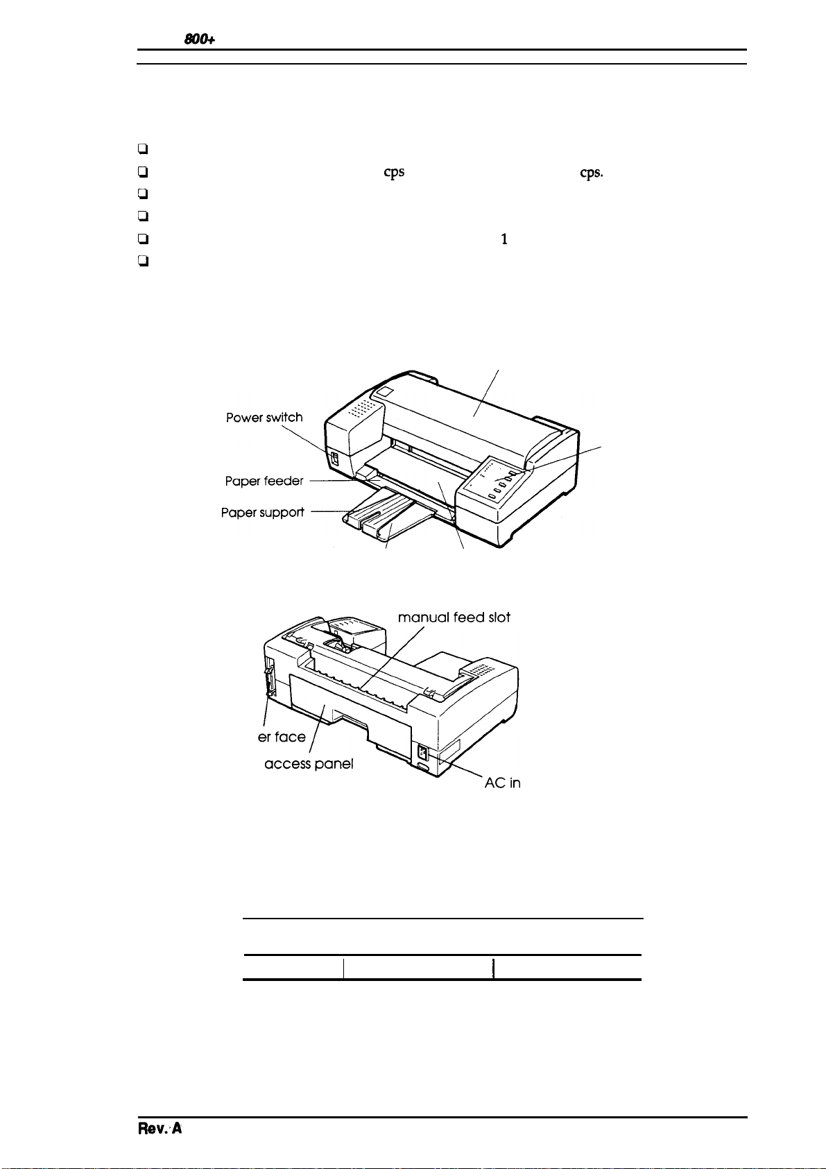
1.1 FEATURES
The Stylus 800+ is a serial inkjet printer that uses a newly developed inkjet technology to produce
superb quality output with high-speed printing. The major features of this printer are:
~
High print quality from a MACH (Multi-Layer ACtuator Head) inkjet technology.
D
Fast printing of LQcharacters at 165
D
Compact design saves precious work space.
D
Built-in auto sheet feeder with a capacity for a
D
Equipped with4 scalable fonts, 5 bitmap LQ fonts, and
Cl
9 character tables for the standard version
15 character tables for the NLSP (National Langauage Support) version.
The figure below shows a view of the printer.
cps
and draft characters at 250
maximum of 100 cut sheets (either A4 or letter).
1
draft font, standard.
Printer cover
cps.
parallel
control panel
Paper separator Paper feeder cover
int
let
Figure 1-1. View of the Stylus 800+
Rev.A
Table 1-1. Consumable for the Stylus 800+
Part No.
I
S020025
Description
I
Ink cartridge
I
I
Black ink cartridge
Type
I
I
1-1
Page 10
Gomrd
oescf@knl
wh18ao&
Su’v&ohhud
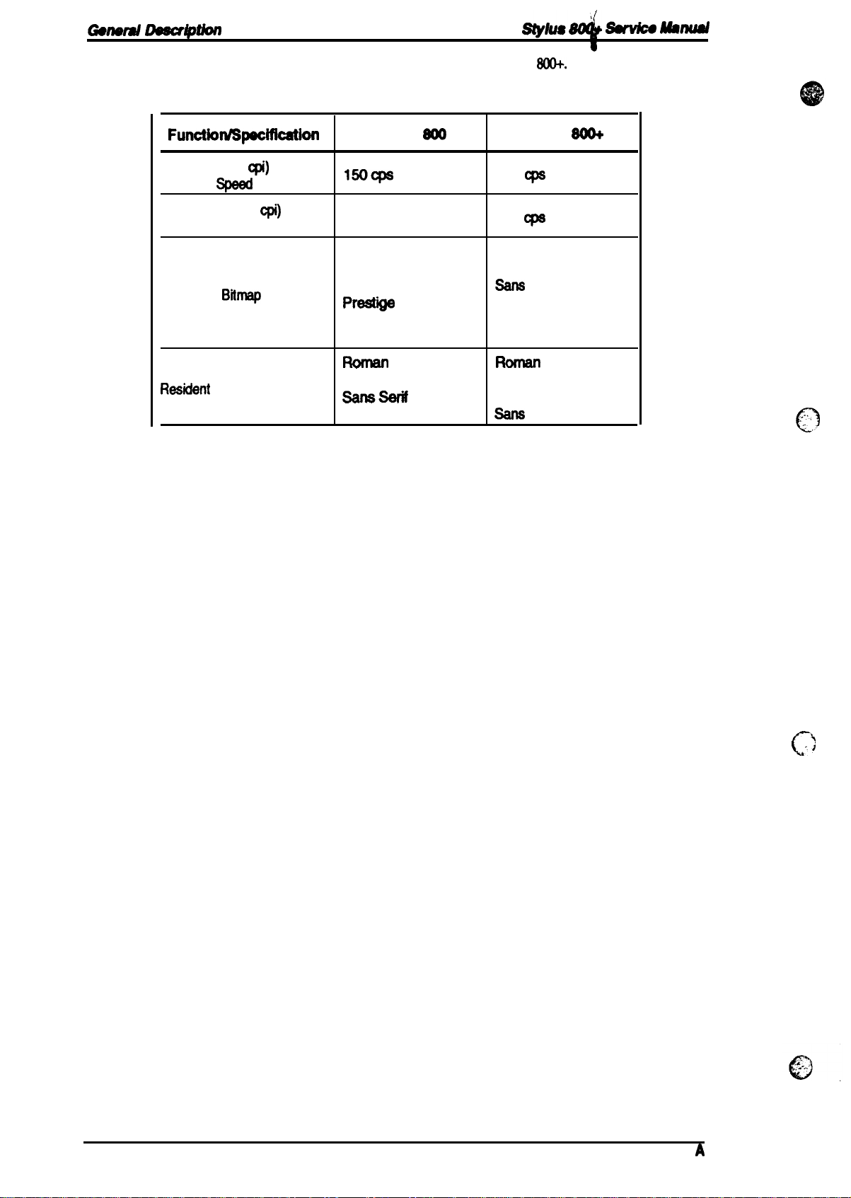
Table
1-2
shows the differences
Function/SpecWation
LQ Fonts (10
Printing
Draft Fonts (10
Printing Speed
Resident
Rasident
cpi)
Spaed
Bitrnsp
Scalable Fonts
in features for the Stylus 800 and Stylus
Table 1-2. Feature Comparison
cpi)
Fonts
stylus
150CPS
cannot printing
Roman ‘
sane serif
Courier
Prest”*
script
Roman T
~=
Saris Serif H
Soo
165
250
Draft
Roman
Ssns
Courier
Prestige
script
Roman T
Saris serif
sane
W+.
stylus
Cps
Cpe
Serif
Serif H
SO&
..,,’,
n
<,,.
1-2
Rev.
..1
c’
A
Page 11
Stylus
800+
service Manual
1.2 SPECIFICATIONS
This section provides detailed statistics for this printer.
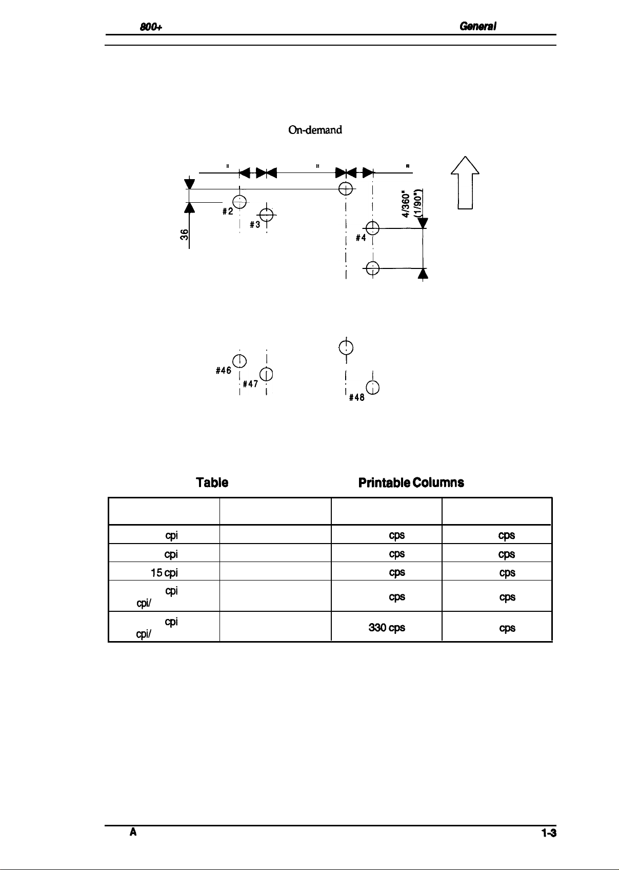
1.2.1 Printing Specifications
GenwW
Description
Print system: Ondernand
Nozzle configuration:
17/360
‘o
%
II
#2y
A
I
I #3
,+
48 nozzles (12 nozzles
1,
60/360
,
#1
i i
I
i
‘d
i i
ii
ii
ii
hi
#45 ‘
9
#’$6Y#47~
I
Figure 1-2. Nozzle Configuration
inkjet system
x
4 staggered columns)
,,
12/3
~
‘O=a
60
i
~$
i’
i #4 i
i’
i’
i i
i
I
i
i,48d)
0
Paper feed
direction
Print direction:
Print speed and printable columns:
Character Pitch
10
cpi
12
cpi
15 cpi
17
cpi
(10
cpi/
condensed)
20
cpi
(12
cpi/
condensed)
Tabie
1-3. Print Speed and
Printable Columns Print Speed (LQ)
80
96
120
137
160
Bidirectional printing with logical seeking control
See table below.
Printabie Coiumns
Print Speed (Draft)
165
CPS
198
C@
246
@s
283
Cpe
330cps
250
300
375
429
500
Cps
Cps
Cps
Cps
Cps
Rev.
A
14
Page 12
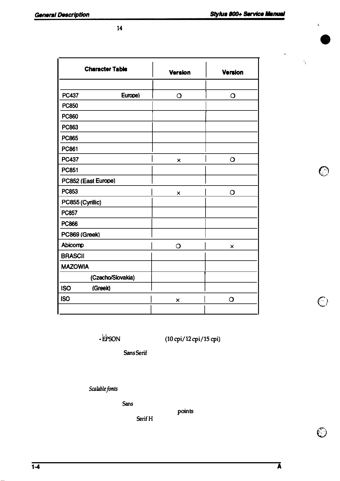
Character sets:
Character tables:
Legal and
See the table below.
14
international character sets.
Chamcter Table
Italic
PC437
{lJ.S./Standard
PC850
(Multilingual)
PC880
(Portuguese)
PC883
(Canadian-French)
PC885
(Nordic)
PC881
(Iceland)
PC437
Greek
PC851
(Greek)
PC852 (East Eurme)
PC853
(Turkish)
PC855 (Cyrillic)
PC857
(Turkish)
Table 1-4. Character Tables
standard
Veraion
o
o
o
1
I
I
Eumtw)
I
1010
1
o
o
o x
Ixlo
x
x
Ixlo
x
x
*
NLSP
Vewaion
0
0
x
x
x
o
o
o
o
Fonts:
PC888
(Russian)
PC889 (Greek)
Abicornp
BRASCII
MAZOWIA
Code
ISO
8859-7
ISO
Latin IT (Turkish)
Bulgaria
(Poland)
MJK
(Czecho/Sbvakia)
(Greek)
(Bulgaria)
o supported
Bitmap fonts —
-
- EPSON Roman
- EPSON
-
- EPSON Prestige
- EPSON Script
Scdiablefmts
-
- EPSON %s Serif
- EPSON Roman T
- EPSON Saris
x Not supported
ii50N
EPSON
Draft
%llS %if
Courier
—
EPSON Roman
SerifH
x
x
Iolx
o
x
x
x
I
Ixlo
x
(lOcpi/12
(10/12/15/proportional)
(10/12/15/proportional)
(10/12/15)
(10/12/15)
(10/12/15)
8-32 points (units= 2 points)
8-32 points (units= 2 points)
8-32
8-32 points (units= 2 points)
cpi/15cpi)
points
(units= 2 points)
o
o
x
o
o
o
o
I
14
Rev.
A
Page 13
Stylus
S00+
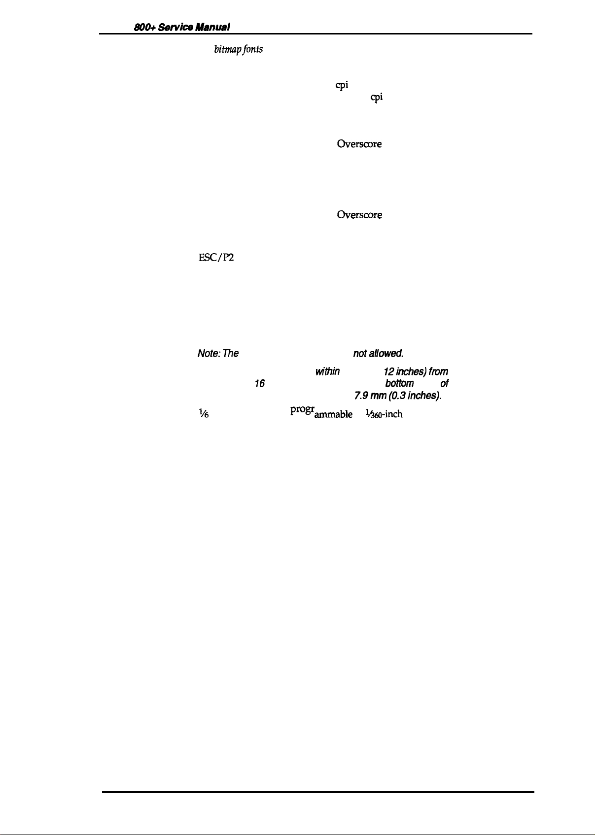
Print mode:
Servke
A4snusl
For
bitrnapfonts
—
General Description
Selection and mixture of the following modes are allowed.
- Print quality (LQ)
- Character pitch (10/12/15
- Condensed (not available with
- Double width
- Emphasized
- Italic
- Double underline
- Strike through
cpi
or proportional)
15
cpi
character pitch)
- Double height
- Double strike
- Underline
-
OverScore
- Shadow / outline
For scalable fonts —
-
Emphasized
- Italic
- Double underline
-
Strike through
- Double strike
- Underline
-
OverScore
- Shadow / outline
Control codes:
Input buffer
Esc/P2
32KB or 8KB (selected using the default setting labeled “Mixed text/
graphics mode”)
1.2.2 Paper Handling Specification
Feeding system:
Feeding pitch:
Paper path:
Feeding speed:
Friction feed from the built-in sheet feeder or manual insertion slot.
Note: The
following operations are
1. Reverse feeding
or 16 mm (0.63 inches) from the
2. Reverse feeding beyond 7.9mm
1,6
or l&in& feed or
Prow
Built-in sheet feeder (front entry)
Manual insertion slot (top-rear entry)
87 rns (at
1/6-inch feed
pitch)
w“thin
3mm (O.
ammable
nota//owed.
12inches) ftvm
Mtom
(0.3inches).
in
1A60-inch
the top edge
edge of the paper.
minimum increments.
Rev. A
1-5
Page 14
General
Deecriptbn
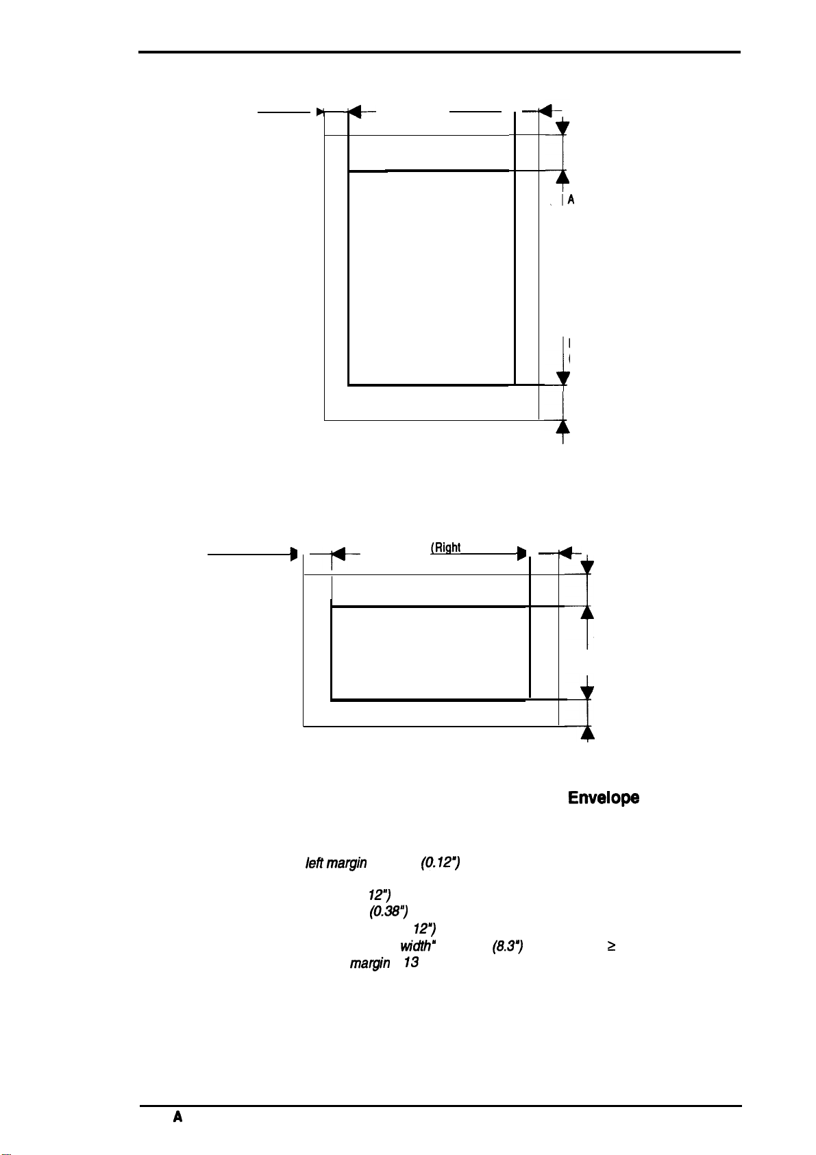
1.2.3 Paper Specifications
Usable paper:
Slykls m
~Mmud
cut sheet
Envelope
With the built-in
size:
skt
feeder —
For European/Paafic version:
A4(WXL :210 mm(83”)x
297mm(11.T’))
For U.S. version:
Letter (W x L: 216 mm (85”) x279 mm (11.0”))
‘IhiClmess:
weight
Quality:
0.06564Bond paper,
o.14mrn(o.oo26
90g/m2 (18 -
Ph&Ompier
- 0.0055”)
241b.
/ 55- 78
paper
With manual insertion —
Width:
Length:
Thickness:
weight
182-216 mm (7.2 - 8.5”)
257- 297mm(lo.1 - 11.7”)
O.(M5-
0.11
52-
90g/m2
rnm(O.0026-
(14 -
0.0043”)
241b
/ 45-
78kg)
Quality: Bond paper, Photocopier paper
#6
(w
X
L :
166
Size:
#lI)(wx
Thickness:
0.16-052
Note: Variatbnsrnpaperthkkness
mm (6%”) X %? mm
L
:240
mm(9k”) X
mm(O.0063
- 0.020”)
W”thi.
104mm(41Z$”))
theprintaMearea mustbe
0.25mm (0.CMW~ orless.
weight:
Quality:
45- 90g/m2 (12Bond paper, Air mail
241b.)
kg)
(354”))
Notes
1. Envekpesare usable only Mthmanualinsertion feed.
2.
Ptintingon envelcpeskguamnte edonlyatmxmal
and humidity.
3. lnsertenve@esinto
themanualinsertion slotsidewaya.
temperature
14
Rev.
A
Page 15
Stylus &MO+ Service Manual
General Description
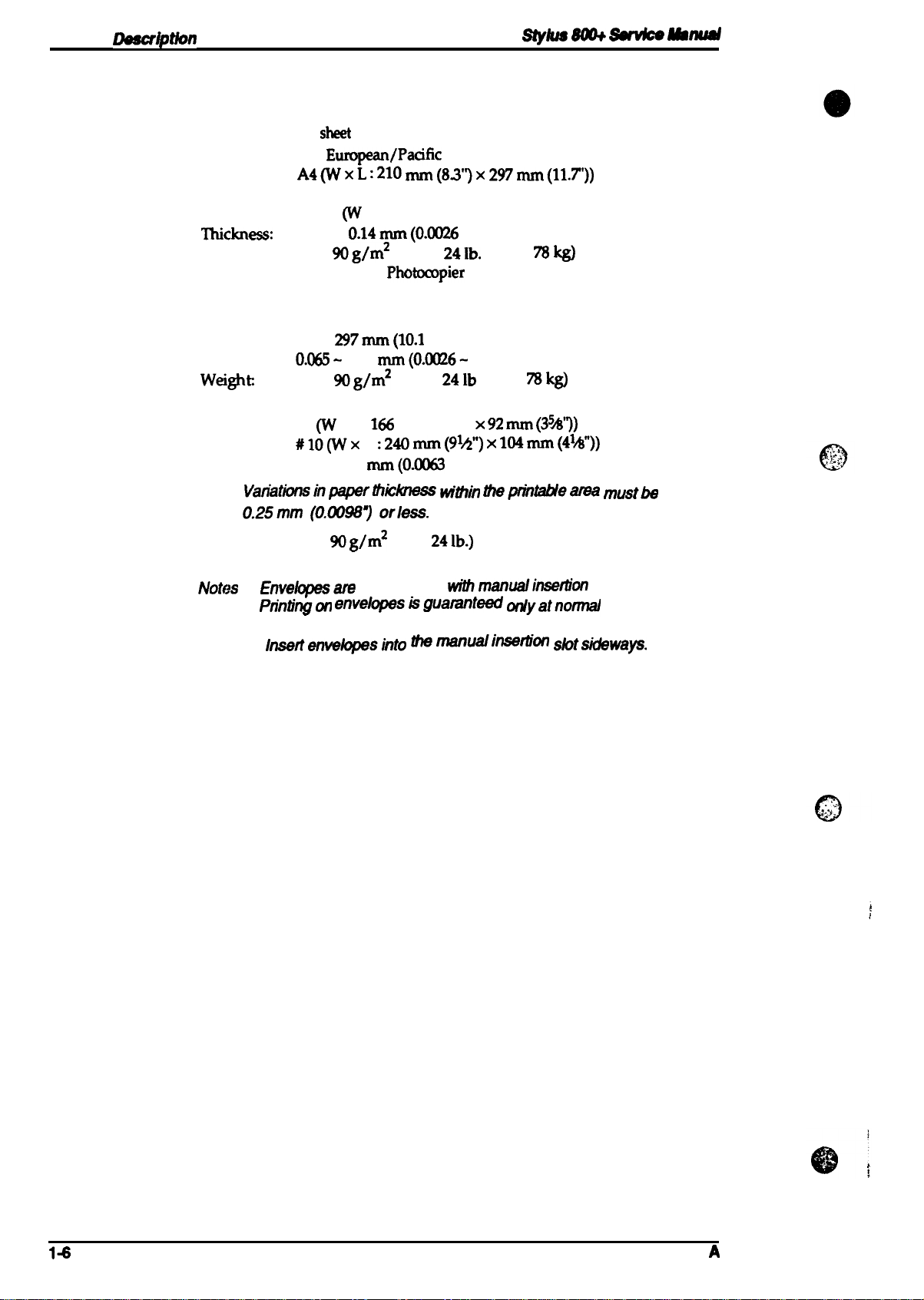
Printable area:
Cut sheet (with built-in sheet feeder)
B
(Left margin) ,
Figure 1-3. Printable Area — Cut Sheet
c
—
t--
(Right margin) ,
Printable area
(Built-in Sheet Feeder)
—
-4
A
(Top margin)
D
(Bottom margin)
-1
-+
Notes:
Cut Sheet / envelopes (with the manual insertion slot)
B
(Left margin)
D
Printable area
c
~Right
margin)
Figure 1-4. Printable Area — Cut Sheet/
(Manual Insertion Slot)
A: The minimum top margin= 3 mm (O. 12”)
B: The minimum Ieflmargin = 3 mm
C: The minimum right margin is
A4 size= 3.0 mm (O.
Letter size =
Manual insertion =3 mm (O.
Manual insertion = ‘Paper
D: The minimum bottom
9.0
12”)
mm
(0.38~
matgin
(0.12”)
127
(Paper widths A4 (210 mm))
w“dth”
207 mm
= 13 mm (0.51”)
—
s
t-
A
J
(Top margin)
D
(Bottom margin)
EnveIoW
(8.3”)
(Paper width 2 A4 (210 mm))
Rev.
A
1-7
Page 16
-nerd
Description
stylus
8m+
~
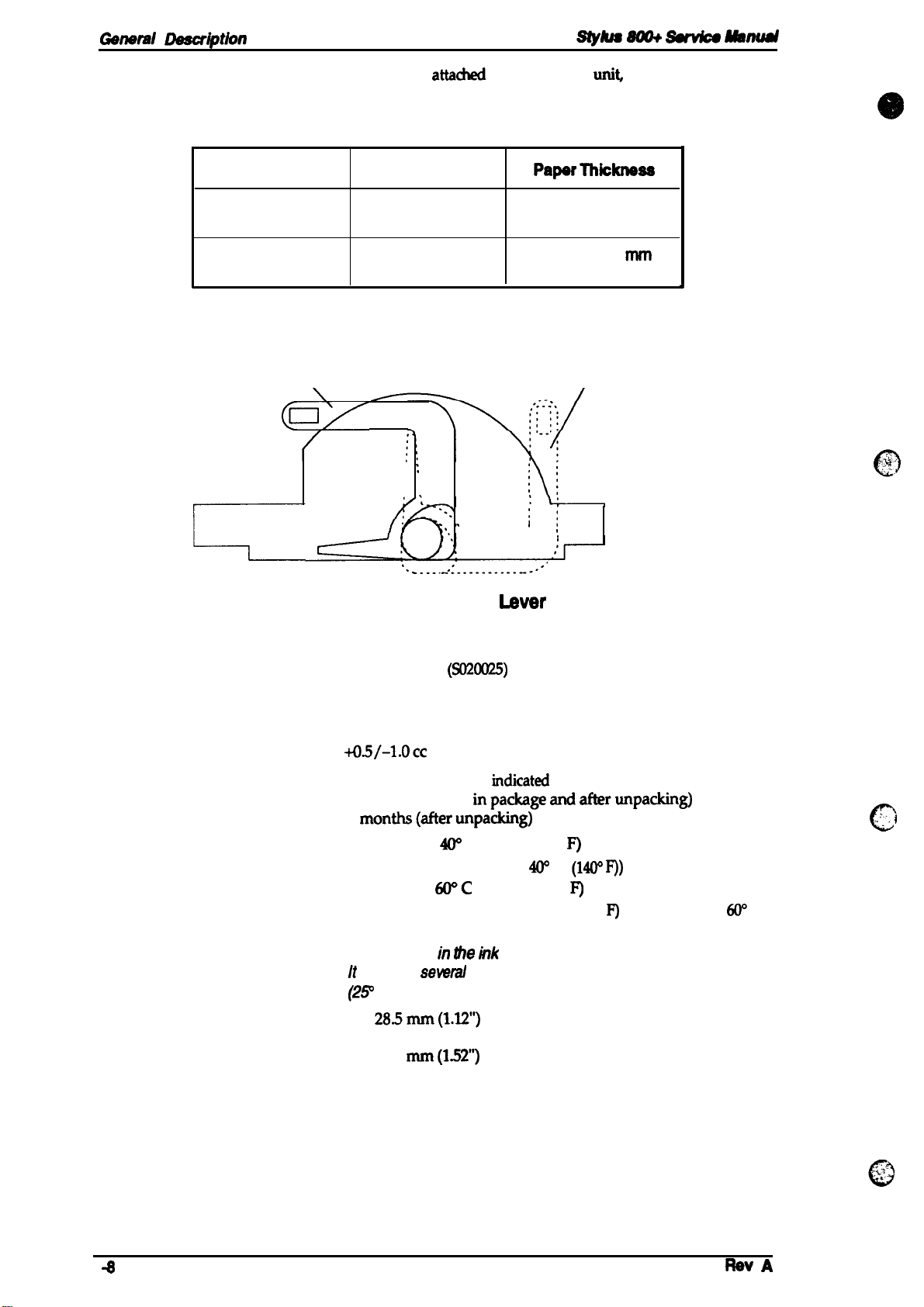
Mstnd
Adjust lever settings:
Lever Position
Plain paper, bond paper
The adjust lever,
position for the paper thickness, as shown below.
attadwd
to the carriage
Table 1-5. Adjust Lever Settings
Paper Type
Left
Right
Cut Sheets
Envelopes
\
\
(Ox
:
:
.
,
, ,
,
,
. . . . . . ------
unit
must be set to proper
Papsr
Thkknsss
0.065-0.11
nun
(0.0026- 0.0056”)
0.16- 0.52
(0.0063-
mm
0.020”)
Envelopes
/
,,
,,
In
0
4
1.2.4 Ink Cartridge
Type:
Ink color:
Print capacity:
Ink
capacity:
Life:
Temperature conditions:
Dimensions:
Figure 1-5. Adjust
Exclusive cartridge
Black
0.7
million characters (LQ)
29.0 +o.5/-l.occ
The effective life from the
2years (total time
6
Storage —
Transport —
Note: Ink freezes in
Width
Depth 54.5 mm (215”)
Height 38.5
months(afterunpacking)
If
requires
(2P
C(77 9).
28.5mm(l.12”)
(SOXXX25)
inpackageandafterunpacking)
-30- m c (-22 - 104°
(Up to 1 month at
-30-
WC (-22 -
(Up to 1 month at 40° C (104° P) or 120 hours at
(140’ P’))
the rnk
sewal
hours to unfreeze at mom temperature
mm(l.52”)
Imer
rndicated
cartridge if kept below-C (26.6°
production date is:
F)
W
C
(14W P))
140”
F)
6(T’
9.
C
‘:”.
c
\
Page 17

Stylus 800+
1.2.5
service Manual
Environmental Conditions
Table 1-6. Requirements for Operation and Storage
Ganwd
Description
Description
Temperature
Humidity
Resistance to shock
Resistance to vibration
Note:
*7
= Operating conditions must be h this range shown h the
*2=
When the pnnteris in the shipping container.
*3= Without condensation.
Humidity
(%RH)
80%
ss~o
*o’Y.
Operating
10- 35° C (50 - 95° F)*
20- 80% RH “1’”
3
1 G, within 1 ms
0.15 G, 10-55 Hz
l
-20- 50° c (-4 - 122°
5- 85% RH ‘2”3
2 G, within 2 ms ● 2
0.50 G, 10-55 Hz ● 2
figure
Print assured range
Storage
Mow.
F)
● 2
10”
c
(5o”
F) (80” F) (95” F) (“F)
Figure 1-6. Temperature/ Humidity Range
1.2.6 Electrical Specifications
Table 1-7. Electrical Specifications
Item
Rated voltage
Input voltage range
Rated frequency range
Input frequency range
Rated current
Power consumption
Insulation resistance
(applying 500
120 V Version
103.5- 132 V 198-264 V
49.5 -60.5 Hz 49.5 -60.5 Hz
Approx.
(self-test with 10
10
line and chassis)
27” C
c
“c
35”
220-240 V Version
120
VAC
220-240
VAC
50-60 Hz 50-60 Hz
0.5 A
13 W
cpi
LQ (self-test with 10
characters)
MQ,
minimum 10
VDC
between AC
(applying 500
0.3 A
Approx.
13 W
characters)
MQ,
minimum
VDC
between AC
line and chassis)
cpi
LQ
Dielectric strength
Rev.
A
1000
VAC rms
1200
-1 minute or
VAC rms
-1 second
(between AC line and chassis)
1500
(beween
VAC rms
‘c ‘ine
and
-1 minute
Chasis)
14
Page 18
Gsnsrd Dssaiption
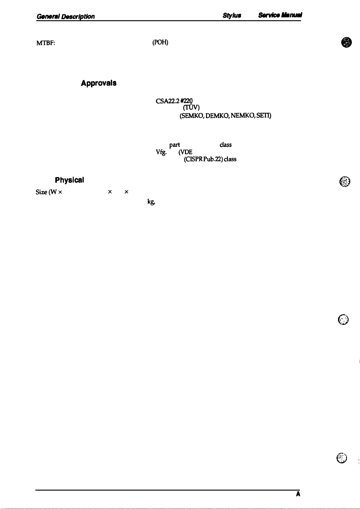
1.2.7 Reliability
stylus 8@+
ssfwicsmm4d
MTBF:
Printhead life:
Total print volume:
1.2.8 Safety
Safety
Radio frequency interference (lWI):
1.2.9
Size(Wx DX H):
Weight
standards:
Physicai
4000 power on hours
1 billion dots per nozzle
75000 pages (with A4 or letter-size paper)
Approvais
US. version:
European version:
US. version:
European version:
Specifications
435 X 264 X 154 mm (17.1 x 10.4x
Approximately 4.8
(POH)
at a duty cycle of 10’Yo
UL1950 with D3
CSA22.2 m
EN 60950
IEC 950
FCC
Vfg.
EN 55022
ka
excluding the ink cartridge
m
(SEMKO, DEMKO, NEMKO, SETI)
part
15, subpart B,
243
(VDE
0878 part 3, part 30)
(CISPR Pub.22) ClaSS
6.1 inches)
ChSS
B
B
-iii.”
c)
1-1o
Rev.
A
Page 19
Stylus
800+
service
Manual
General Dasoription
1.3 INTERFACE SPECIFICATIONS
The Stylus 800+ is equipped with an 8-bit parallel interface, standard.
Data format:
Synchronization:
Handshaking:
Signal level:
Adaptable connector:
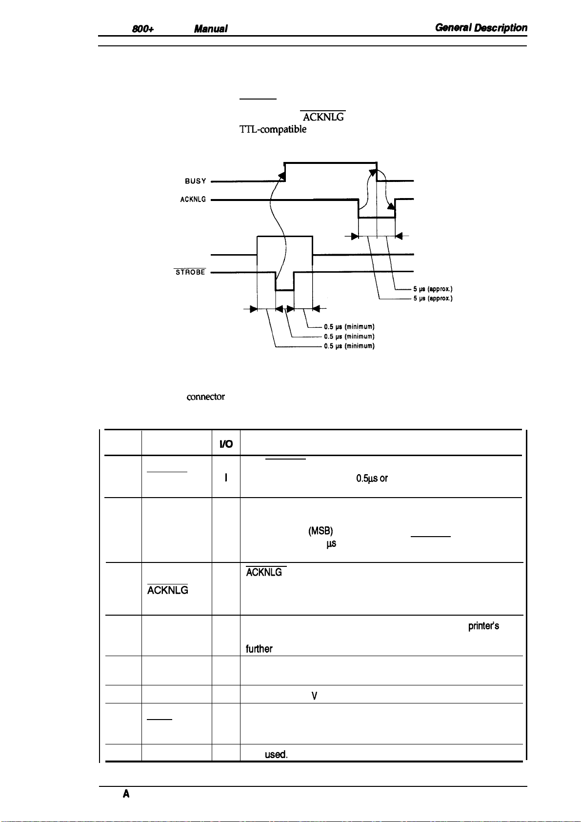
Data transmission timing:
ACKNLG
DATA
Figure 1-7. Data Transmission Timing
8 bit parallel
STROBE pulse synchronization
By BUSY and
TI’L-compatible
36-pin 57-30364) (Amphenol) or equivalent
See Figure 1-7.
ACKNLG
h
signals
level
i
[
)
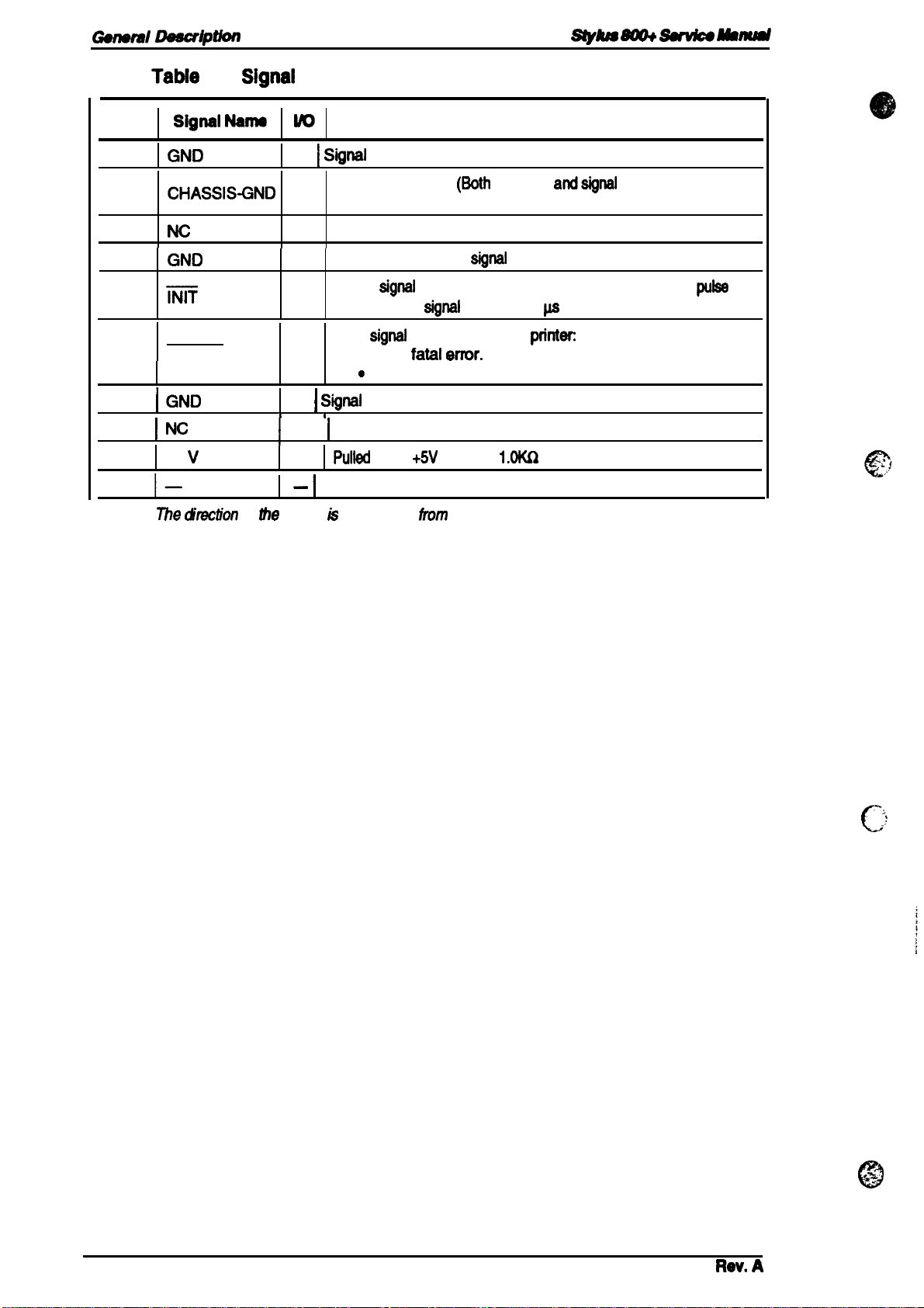
Table 1-8 shows the
comector
Table 1-8. Signal and Connector Pin Assignments
Pin No. Signal Name
STROBE
1
2-9
10
11
12
DATA 1-8
ACKNLG
BUSY
PE
pin assignments and signal functions of the 8-bit parallel interface.
I/o
The STROBE pulse is used to read data from the host computer.
1
The pulse width must be
and data is latched with rising edge of this signal.
DATA 1-8 are parallel data bits. When one of these signals is
HIGH, the data bit is 1; when LOW, the data bit is O. The most
significant bit
I
maintained for 0.5
edge.
ACKNLG
approximately 10 p.s. This signal goes LOW on completion of
o
data reception to indicate the printer is ready to receive further
data.
The BUSY signal informs the host computer of the
o
status. When this signal is HIGH, the printer cannot accept
futiher
data.
This signal indicates whether paper is available in the printer or
o
not. A HIGH level indicates no paper.
(MSB)
p.s
is the acknowledge pulse, with a width of
Description
0.5p.sor
is DATA 8. The signal state must be
on either side of STROBE signal’s active
more. Normally, it is HIGH,
printet’s
13
14
15
Rev.
SLCT
AFXT
NC
A
o
Pulled up to +5 V through a 1.OK S2 resistor in the printer.
If this signal is set to LOW, the printer automatically performs
I
one line feed upon receipt of a CR (carriage return) code. The
status of this signal is checked only at power on and initialization
—
Not
USed.
1-11
Page 20
Garleml
Descdption
Styhm
m
Sutdc9 Msmd
Pin No.
16
17
18
19-30
31
32
33
34
35
36
Note:
Tabie
1-8.
I
Signai Narno
I GND
CHASSIS-GND
Nc
GND
m
ERROR
I GND
I
NC
+5
v
l—
Z5e
&ection of
Signai
and Connector Pin Assignments (Continued)
I
I
W
— I
Signai
Chassis ground.
—
connected in the printer.)
—
Not used.
—
Twisted-pair return
if this
i
width of this
This
o
—
I
Signai
1 1
—
I
!
tie
signal h as viewed
Not used.
—
Puited
,
—
I
Not used
ground.
signai
go& LOW, the printer is initialized. The
signat
goes LOW if the
● has a
.
runs
fatai wmr.
out
ground.
up to
+5V
(reserved).
Description
(i30th
chassis
signai
ground.
signai
must be 50 @ or more.
printec
of paper.
through
tkom
the
1.OKQ
printer.
resistor in the
andsignai
ground are
pulse
printer.
c
%,
@
‘,
;’
.
1-12
Rav. A
Page 21
Stylus
&WO+
Sarvke Manual
General Dsscrlptkm
1.4 PRINTER OPERATIONS
This section describes the basic operations of the printer.
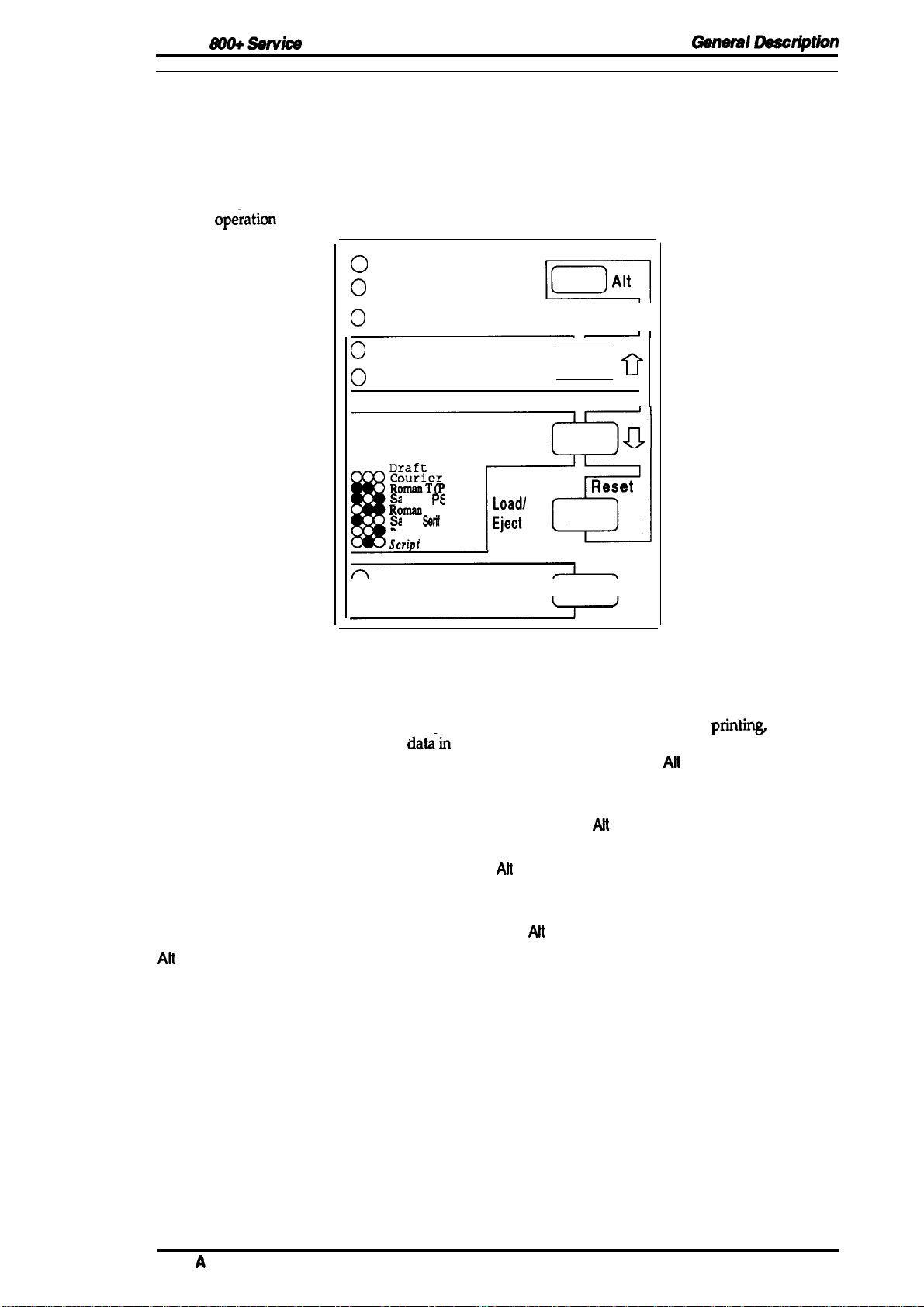
1.4.1 Control Panel
The control panel for this printer contains five non-lock type push buttons and nine LED indicators
for easy
ope;ation
of the various printer functions.
O
Data
O
Paper Out
0
Ink Out
O
Economy
O
Condensed
E=El
II
[:: 1
0
Buttons
Pause
Economy/Condensed
Font
Load/Eject
Alt
000
m
Draft
ourier
omarIT
S)
ii..
San:
#’
s H ( S)
D,..,,
lwum
Saris
B--
B
“ Pause
Sarif
Prestige
scriDt
‘on’
I.oadl
Eject
m
FIUl
Reset
II
Figure 1-8. Control Panel
Switches printer status between printing and no
print
datz-in
the input buffer.
When you hold down this button and the
for 2 seconds, the printer initiates printhead cleaning.
Selects economy or condensed printing alternately. Also works as a
reverse micro feed button, if the
Selects one of the available fonts. Also works as a forward micro
feed button, if the
When you press this button, the printer either loads new paper into
the printer or ejects paper currently in the paper path. Also works
as a reset button, if the Ah button has been pressed.
This button alternates functions of certain buttons. When you hold
down this button in pause mode for 3 seconds, the printer moves
the carriage to the ink cartridge installation/replacement position.
Ait
button has been pressed.
Alt
button has been pressed.
Alt
printin~
button in pause mode
if there is
Indicators
Pause
Data
Paper Out
Ink Out
Economy/Condensed
Font
Rev.
A
Lights when the printer is in pause mode.
Lights when there is print data in the input buffer.
Lights when the printer is out of paper. Blinks if a paper jam occurs.
Lights when the printer detects an ink end in the ink cartridge.
Blinks when the ink level becomes low.
This LED shows the currently selected mode.
Indicates the currently selected font.
1-13
Page 22
Gen9m/ Lkscd@n
1.4.2 Panel Operation at Power On
SiJdu88m+
~
Wnual
You can turn on the following functions
panel.
Self-test mode:
Hex dump mode:
monstration mode:
De
Smudge prevention mode:
Other functions that can be activated from the control panel at power on, such as the default setting
mode and the initial ink charge mode, are described in the sections that follow.
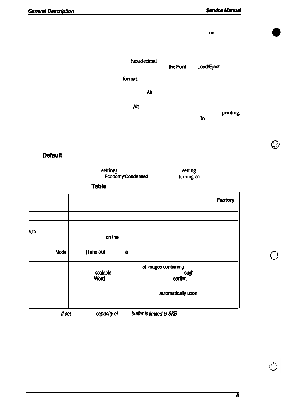
1.4.3
The printer lets you set and save some default settings that it will start with after every
initialization. You can define the
setting mode by holding down the
Defauit
Setting
Start self-test printing by turning the printer on while holding down
the Font button (LQ self-test) or
Start the built-m
printer on while holding down
Once this mode is selected, the printer pMts all received data m
hexadecimal
Start printing of a demonstration page by turning on the printer
while holding down the Ah button.
Enter smudge prevention mode by turning on the printer while
holding down the AH and Font buttons.
If the paper has a tendency to smudge during high duty
you can prevent smudges using this feature. Jn this mode, the
printer waits a few
settings
Ecofimy/Condensed
at
power on by holding down buttons cm the control
LoadEject
hexadwirnal
hrnat.
seconds after printing a line to line feed.
in the table below in default
data dump print mode by turning the
(he Font
button while
button (Draft self-test).
and
LOWE~
setting
mode. Start default
tuming-6n
the printer.
buttons.
printins
,..
..”’,
,,..
0
Tabie
1-9. Default Setting ttem
Menu
Contents
Character Table Selects the character table
ON: Print direction is selected automatically for optimal print
4uto
Print Direction
Network l/F
Mixed Text/
Graphics Mode
Auto Line Feed receipt of the CR code.
Note:
●
Mcde
1 =
OFF: For normal use.
ON: Line feed operation is performed
OFF: No line feed operation with CR code.
/fset
to ON, the
quality (alignment).
OFF: Depends
ON: For netvvorkenvironments, such as LocalTalk.
(Thne+xh
ON: For
ON: To ensure proper printing
and
MS
onthe
printing ie disabled.)
normal environments. (Time-out printing is enabled.)
ecalable
Wotd
capcityof
fonts using certain applications,
or WordPerfect version 5.1 or
Description
ESC U command.
input
bufferh finu’tedto 8KB.
ofimagescontaining
automsticaltyupon
graphics
~lh
eartier.
as
Fectoty
Setting
ON
OFF
c)
OFF
OFF
1-14
Rev.
A
Page 23
Stylus
800+ Setvica
Manual
General Daacription
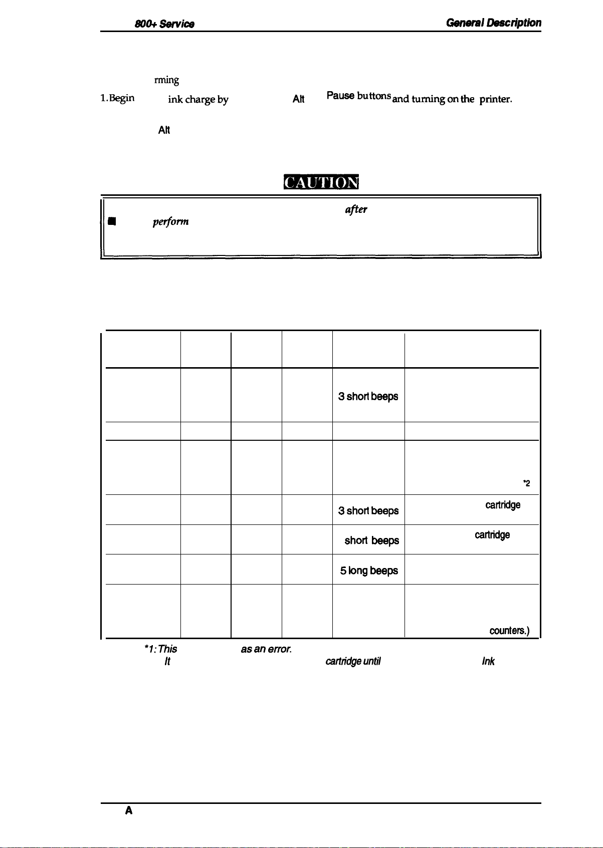
1.4.4 Initial Ink Charge
When the printer is setup for the first time, the printer’s entire ink supply path must be filled with
rming
ink by perfo
the initial ink charge operation, as described below.
1. Be@
2.
3. Press the
The Pause
initial
inkchargeby
Install the ink cartridge.
Alt
button.
LED blinks while the initial ink charge operation is in progress, and when it completes,
pressing the
Alt
and
Pa~butions andtirningon the
pfiter.
the printer automatically becomes ready.
■
The ink cartridge
N
Do not
perjorm
must be
installed immediately
afler
unpacking the package.
the initial ink charge operation more than twice on the same printer.
Otherwise, the operation consumes too much ink in the cartridge and shortens the life of
the waste ink tank.
1.4.5 Error Conditions
The printer detects various errors and indicates them with the LED indicators and the buzzer.
Table 1-8. Error Codes
Error
Paper end
Paper
LED
ON
Ink End
LED LED
OFF
Pause
OFF
Buzzer Recovery
Load paper and press the
~ ~hon ~wp
following buttons:
1. Pause
2. Load/Eject
Paper jam
Ink low ● 1
Ink end
No ink cartridge
Carriage error
Waste ink tank
over-flow
Notes:
“1: This
●
2: It is not
error.
BLINKS
OFF
OFF
OFF
OFF
OFF
is not treated as an
OFF OFF
BLINKS
ON
ON
OFF OFF
ON
error.
necessary to replace the ink
3 short beeps Same as above.
—
OFF
OFF
No beeps
a Shoti ~ps
3
‘hod be~
~ ~ng beep
BLINKS 3 short beeps
caflndge until
the printer detects the
Press Pause and replace
the ink cartridge with a new
one. Then, press Pause
again to resume printing.
Replace the ink
catlridge
V
and press Pause.
Install the ink
cattridge
and
press Pause.
Tum the printer off and back
on again.
Service maintenance
required. (Replace the waste
ink absorbing material and
reset the protect
munters.)
Ink
End
Rev.
A
1-15
Page 24
1.5 MAIN COMPONENTS
The main
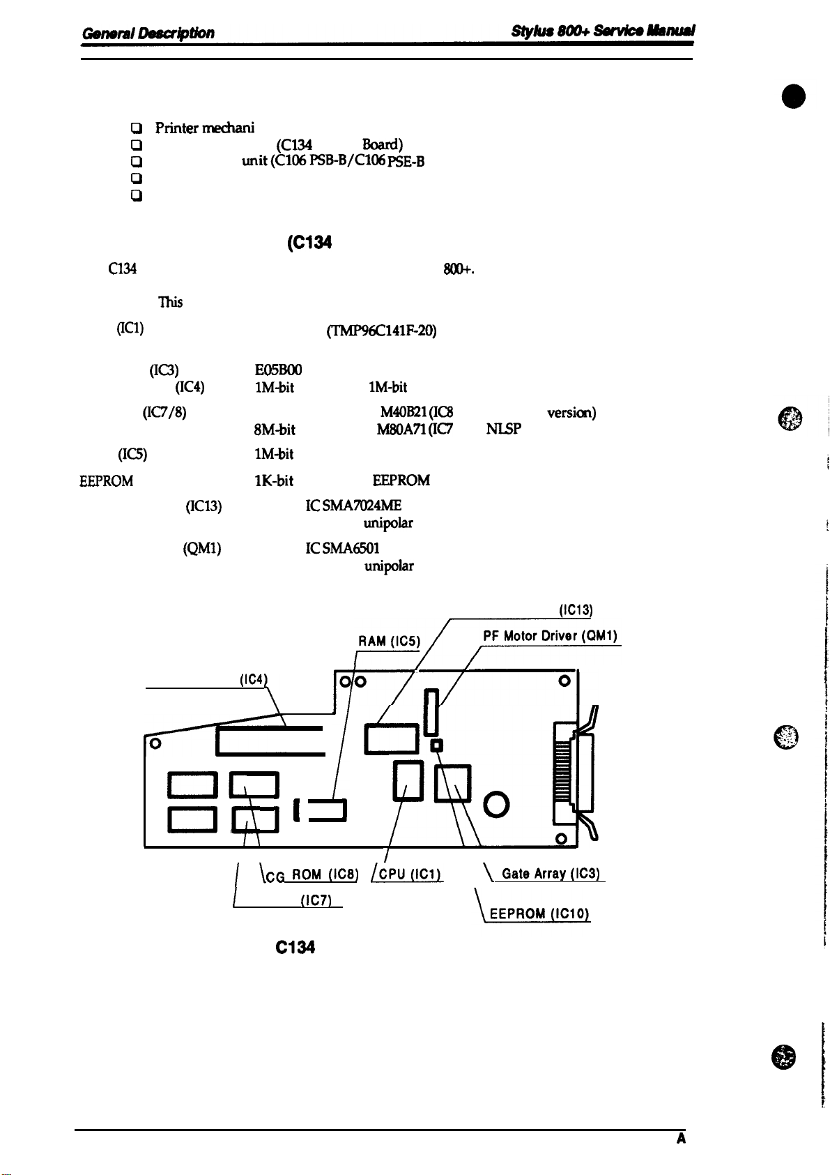
1.5.1 Main Control Board
The
the host computer and processing received print data, as well as control of the whole printer
mechanism.
CPU
Gate array
Program ROM
CG ROM
RAM
EEPROM
CR motor driver
components
o
PMtermechanl
Cl
Main control board
0
Power supply unit(C106PSB-B/C106
0
Control panel
0
Housing
of this printer are:
“sm (M-4611)
(C134
(C134
C134
MAIN
(ICl)
(n)
(IC1O) IK-bit
board is the main
This
board consists of the following components
(IC3)
(IC4)
(IC7/8)
(IC13)
Constant current
controller of the Stylus
16-bit CPU
19.6608 MHz operating clock
E05BO0
IM-bit
EPROM or
4M-bit mask ROM
8M-bit
mask ROM
IM-bit
PSRAM
(64x 16 bit)
Hybrid IC
MAIN Baud)
PSE-B
MAIN Board)
~141F-20)
IM-bit
M40B21 (IC8
M80A71 (IC7
EEPROM
SMA7024ME
unipolar
Board)
800+.
It takes charge of interfacing with
mask ROM
/ for standard
/ for
drive
NISP
versicm)
version)
PF motor driver
Program ROM
ml,
n
o
(QM1)
Hybrid IC
Constant voltage
(IC4
I), I t
I
\
CG
H
~
CG ROM
Figure 1-9.
SMA6501
unipolar
Fr~
I
\
I
drive
CR Motor Driver
/
1
I
‘
[
0
/
ROM (Ica)
(IC7)
C134
MAiN Board Component Layout
(!W!_@L
\\
\
\
@teArray(lc3)
(IC13)
.,.
..>s
-.;:.
o
1-16
Rev.
A
Page 25
Stylus
S00+ Sarvica
Manual
General Daacription
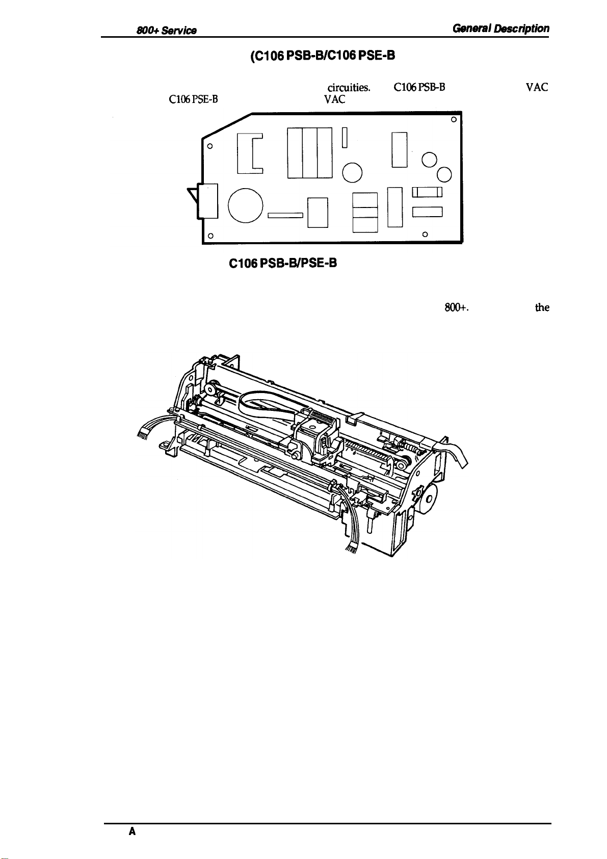
1.5.2 Power Supply Unit
The power supply unit converts input AC voltage and generates the different DC voltages required
by the printer mechanism and other electrical
input, and the
C106 PSE-B
board is for 220 to 240
Figure 1-10.
(C106 PSB-B/C106 PSE-B
circuities.
VAC
input.
CI06 PSB-WPSE-B
Board Component Layout
The
Board)
C106 PSB-B
board is for 120
VAC
1.5.3 Printer Mechanism (M-4811)
The M-4811 printer mechanism is specifically designed for the Stylus
carriage assembly, which includes the printhead and the ink supply system, the carriage motor, the
paper feed motor, the paper feeding mechanism, and the pump mechanism.
800+.
It consists of
the
Rev.
A
Figure 1-11. Printer Mechanism (M-4811)
1-17
Page 26
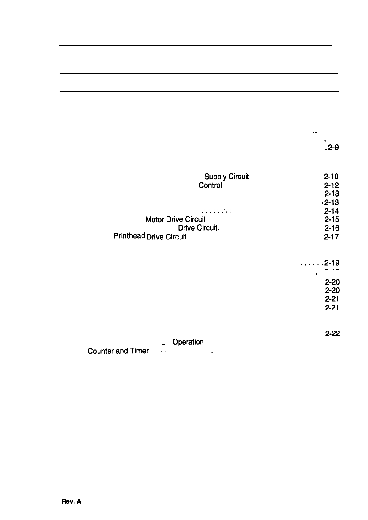
Chapter 2 Operating Principles
Table of Contents
“ “
. . 2-6
.
2-7
. 2-9
2-1o
2-10
2-12
2-I3
2-13
2-14
2-15
2-16
2-I7
2-1
2-1
2.1 OVERVIEW
2.2 PRINTER MECHANISM OPERATING PRINCIPLES
2.2.1
2.2.2 Carriage Drive Mechanism . . . . . . . . . . . . . . . . . . . . . . . . . . . . . . . . . . . 2-4
2.2.3 Paper Feed Mechanism. . . . . . . . . . . . . . . . . . . . . . . . . . . . . . . . . . . . . . 2-5
2.2.4 Ink System. . . . . . . . . . . . . . . . . . . . . . . . . . . . . . . . . . . . . . . . . . . .
2.2.5 Pump Mechanism . . . . . . . . . . . . . . . . . . . . . . . . . . . . . . . . . . . . . . . . .
2.2.6 Cap Mechanism.. . . . . . . . . . . . . . . . . . . . . . . . . . . . . . . . . . . . . . . . . .
2.3
Printer Mechanism. . . . . . . . . . . . . . . . . . . . . . . . . . . . . . . . . . . . . . . . . . 2-2
2.2.2.1 Adjust Lever . . . . . . . . . . . . . . . . . . . . . . . . . . . . . . . . . . . . . . . . 2-4
OPERATING PRINCIPLES OF THE CIRCUITS
2.3.1
2.3.2 Operating Principles of the Main
Operating Principles of the Power
2.3.2.1 Reset Circuits . . . . . . . . . . . . . . . . . . . . . . . . . . . . . . . . . . . . . .
2.3.2.2 SensorCircuits . . . . . . . . . . . . . . . . . . . . . . . . . . . . . . . . . . . . .
2.3.2.3 InkEnd Detection . . . . . .
2.3.2.4 Carriage
2.3.2.5 Paper Feed Motor
2.3.2.6
Printhead DriveCircuh
MotorDfiveCircuh
DriveCircufi.
SupplyCircufi
Control
.....:...
. . . . . . . . . . . . . . . . . . . . . . . . . . . . . . .
Circuit . . . . . . . . . . . . . . . . . .
. . . . . . . . . . . . . . . . . . . . . . . . . . .
. . . . . . . . . . . . . . . . . . . . . . . .
. . . . . . . . . . . . . . . . .
. . . . . . . . . . . . . . . . . . . .
2.4
INK SYSTEM MANAGEMENT
2.4.1 InkOperations. . . . . . . . . . . . . . . . . . . . . . . . . . . . . . . . ... ...
2.4.1.1
2.4.1.2
2.4.1.3
2.4.1.4
2.4.1.5
2.4.1.6
2.4.1.7
2.4.1.8
2.4.1.9
2.4.2 CounterandTimer. . . :. . : . . . . . . . . . . . . . . . . . . . . . . . . . . . . . . . . . . 2-23
2.4.2.1 Refresh-l Timer... . . . . . . . . . . . . . . . . . . . . . . . . . . . . . . . . . . 2-23
2.4.2.2 Flushing Counter. . . . . . . . . . . . . . . . . . . . . . . . . . . . . . . . . . . . 2-23
2.4.2.3 CL Counter K . . . . . . . . . . . . . . . . . . . . . . . . . . . . . . . . . . . . . . 2-23
2.4.2.4 Protect Counter. . . . . . . . . . . . . . . . . . . . . . . . . . . . . . . . . . . . . 2-23
PowerOnOperation . . . . . . . . . . . . . . . . . . . . . . . . . . . . . . . .
Cleaning Operation. . . . . . . . . . . . . . . . . . . . . . . . . . . . . . . . . .
Standby Operation . . . . . . . . . . . . . . . . . . . . . . . . . . . . . . . . . .
Initial Charge Operation . . . . . . . . . . . . . . . . . . . . . . . . . . . . . .
Refresh Operation. . . . . . . . . . . . . . . . . . . . . . . . . . . . . . . . . . .
Cleaner Blade Operation. . . . . . . . . . . . . . . . . . . . . . . . . . . . . . 2-22
InkCartridge(l/C) Replacement Operation. . . . . . . . . . . . . . . . 2-22
Disengage OnOperation . . . . . . . . . . . . . . . . . . . . . . . . . . . . .
Micro Absorbing
OPeration
. . . . . . . . . . . . . . . . . . . . . . . . . . . . 2-23
....s” 2-19
2-18
---
.
z-19
2-21
2-=
2-20
2-20
2-21
Rev.A
2-I
Page 27
List
of Figures .
Figure 2-1. Functional Block Diagram of the Printer Mechanism. . ..........2-1
Figure 2-2. Structure of the
Figure 2-3. Structure of the
Printhead
Printhead
1 . . . . . . . . . . . . . . . . . . . . . ..........2-2
2. . . . . . . . . . . . . . . . . . . . . ..........2-2
Figure 2-4. Principles of the Printing Operation 1 . . . . . . . . . . . . . . . . . . . . . .. 2-3
Figure 2-5. Principles of the Printing Operation 2 . . . . . . . . . . . . . . . . . . . . . . .2-3
Figure 2-6. Carriage Drive Mechanism. . . . . . . . . . . . . . . . . . . . . . . . ........2-4
Figure 2-7. Adjust Lever. . . . . . . . . . . . . . . . . . . . . . . . . . . . . . . . . . . . . . . . . . . 2-4
Figure 2-8. Paper Feed Mechanism 1 . .
.’.
. . . . . . . . . . . . . . . . . . . . . . . .. ...2-5
Figure 2-9. Paper Feed Mechanism 2 . . . . . . . . . . . . . . . . . . . . . . ..........2-5
Figure 2-10.
Figure 2-11.
Figure 2-12.
Figure 2-13.
Figure 2-14.
Figure 2-15.
Figure 2-16.
Figure 2-17.
Figure 2-18.
Figure 2-19.
Figure 2-20.
Figure 2-21.
Figure 2-22.
Figure 2-23.
Figure 2-24.
Diagram of the Ink System. . . . . . . . . . . . . . . . . . . . . . .........2-6
Pump Mechanism Block. . . . . . . . . . . . . . . . . . . . . . ...........2-7
Pump Operation . . . . . . . . . . . . . . . . . . . . . . . . . ..............2-8
Cap Mechanism . . . . . . . . . . . . . . . . . . . . . . . . ...............2-9
Block Diagram of the Circuits. . . . . . . . . . . . . . . . . . . . . . . .. ...2-10
Power Supply Circuit Block Diagram. . . . . . . . . . . . . . . . . . . . . . 2-11
Main Control Circuit Block Diagram. . . . . . . . . . . . . . . . . . . . . . .2-12
Reset
CirWt
Block Diagram . . . . . . . . . . . . . . . . . . . . . . . .....2-13
Sensor Circuit Block Diagram . . . . . . . . . . . . . . . . . . . . . . .....2-13
Ink End Detection. . . . . . . . . . . . . . . . . . . . . . . . . . . . . . . . .....2-14
Carriage Motor Drive Circuit Block Diagram. . . . . . . . . . . . .....2-15
Paper Feed Motor Drive Circuit Block Diagram . . . . . . . . . .....2-16
Printhead
Printhead
Drive Pulse . . . . . . . . . . . . . . . . . . . . . . . . . . . . .....2-17
Drive Circuit Diagram. . . . . . . . . . . . . . . . . . . . . . . .. .2-17
Relationship of Ink System Operation to Carriage Position .. ...2-18
List of Tables
Table 2-1. Carriage Drive Motor Specification . . . . . . . . . . . . . . . . . . . . .. ....2-4
Table 2-2. Adjust Lever Position . . . . . . . . . . . . . . . . . . . . . ...............2-4
Table 2-3. Paper Feed Drive Motor Specification. . . . . . . . . . . . . . . . . . . . . . .. 2-5
Table 2-4. Pump Mechanism Operation. . . . . . . . . . . . . . . . . . . . . . .........2-8
Table 2-5. DC Voltage Distribution. . . . . . . . . . . . . . . . . . . . . . . . . . . . . .....2-10
Table 2-6. Carriage Motor Drive Modes. . . . . . . . . . . . . . . . . . . . . . . . . .....2-15
Table
2-7. Paper Feed Motor Drive Modes . . . . . . . . . . . . . . . . . . . . . . .....2-16
. .
c’
I
I
1
2-ii
Rev.
A
Page 28
Stylus
800+ Satvics
Manual
2.1 OVERVIEW
OpaUng
Ftincipbs
T’& section describes the operating
circuits.
prinaples
for the Stylus
800+
printer mechanism and electrical
2.2 PRINTER MECHANISM OPERATING PRINCIPLES
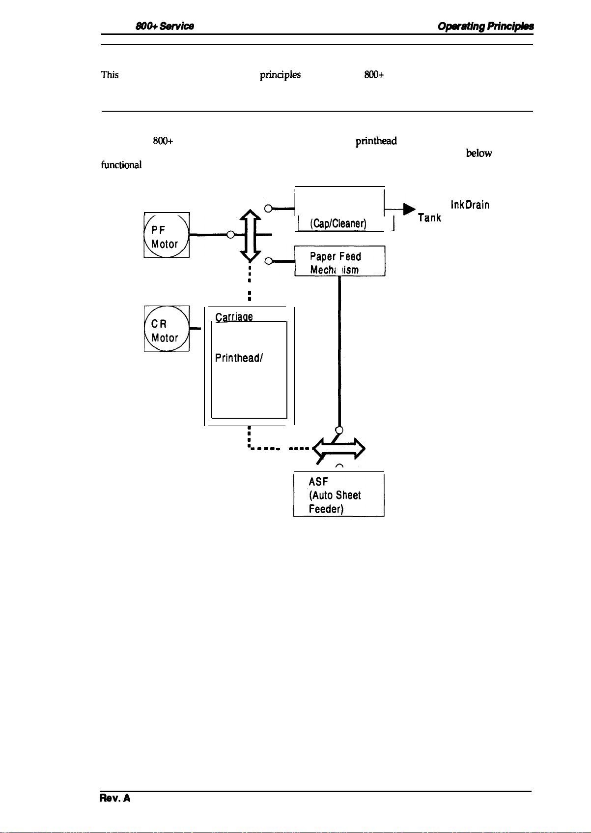
The Stylus
carriage drive mechanism, pump mechanism, and various
functioml
800+
printer mechanism is composed of the
block diagram of the printer mechanism.
Pump
1
I
o-l
~toJ--w
m
●
n
m
■
rriaae
U
CR
Motor
!%
nit
Mechanism
‘(&p’c’caner)
printhead
‘
unit, paper feed mechanism,
sensors. The figure
L
Waste
+-
‘an’
-,
E
Printhead/
Filter/
Driver Circuit
below
Inl- ‘--’-
K
uraln
shows a
m
m
m
% . . .
m ■ . . .
(
.
$+
M
Figure 2-1. Functional Block Diagram of the
Printer Mechanism
Rav.A
2-1
Page 29
Opwating
Princ@h!ss
2.2.1 Printer Mechanism
Stylus Wl+
~tillad
printer mechanism
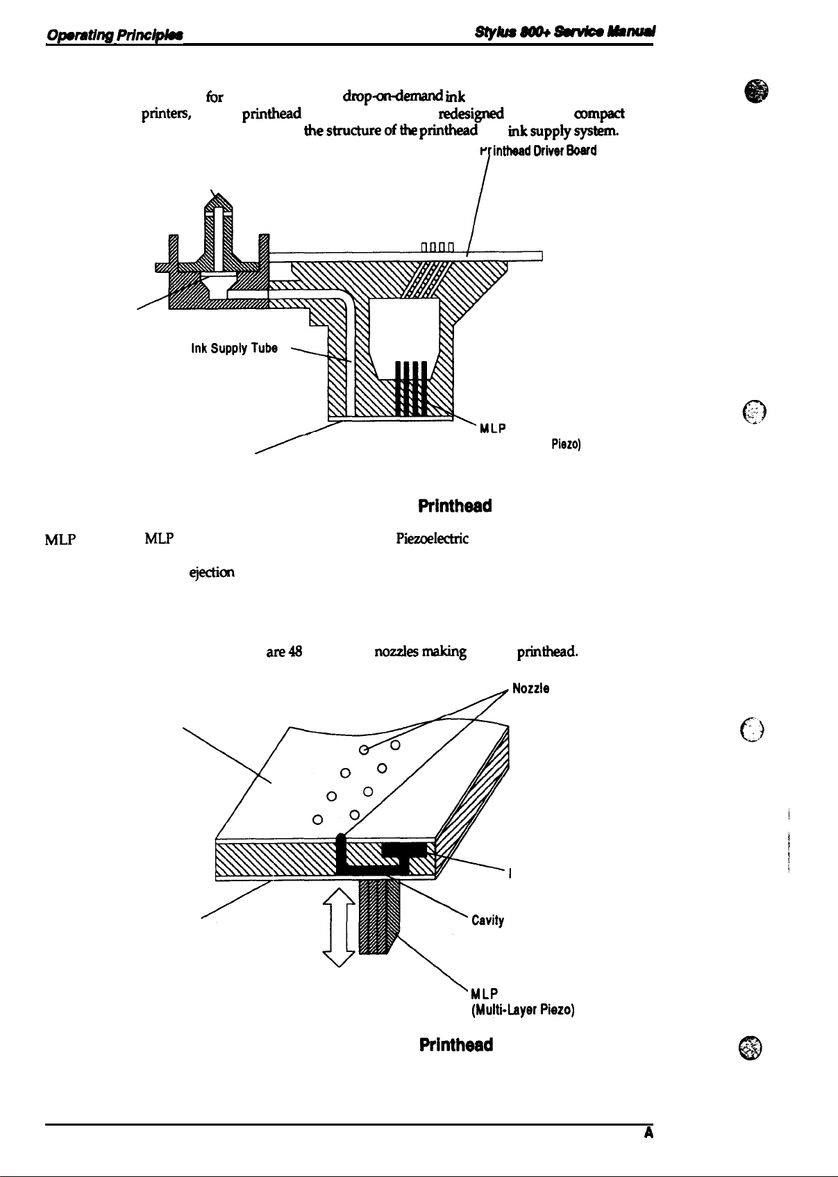
The
EPSON ink jet
highly reliable. The figure below shows
printem,
Cartridge
Filter
Needle
fbr
this printer uses a
but the
\
Cavity Set
(Nozzle)
printhead
has been completely
dmpawknand rnk
thestructureofthe
jet system similar to all other
wdesigned
printhead
to make it
and
rnksupplysystem.
P
intheed IMver Soerd
I
(Multi-Layer
Piezo)
a)mpact
and
MLP
Cavity
❑ Nozzles
Nozzle Plate
Figure
MLP
is the abbreviation for Multi-Layer
(voltage) is applied, this element pushes the vibration plate, compressing the cavity
for ink
Ink supplied from the ink cartridge is stored in this space and is ejected from the
nozzles when the vibration plate compresses this area.
These eject ink against the paper’s surface in response to the application of the
print signal. There
ejectkm
2-2.
Structure of the
from the nozzle.
are4S individual
Printhead
Piezoelectric
nmzlesmaking
1
element- When a drive pulse
up this
printhead.
>’022’8
supply
Tank
nk
i
2-2
Vibration Plate
Figure 2-3. Structure of the
‘ MLP
(Multi-byer Piezo)
Printhead
2
Rev.
A
Page 30
Stylus
Principles of the Printing Operstion
The
1.
S00+
service Manual
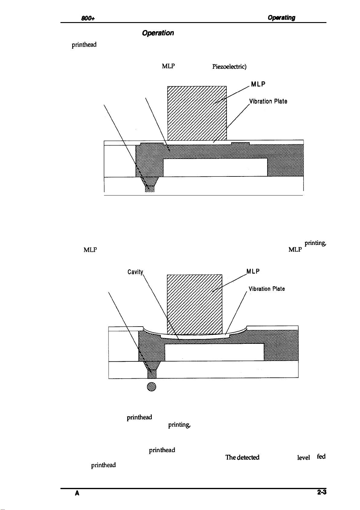
printhead
Normal state
performs the following operations to eject ink from each nozzle:
Opsfating
Principles
No electrical charge is applied to the
of the cavity, and pressure in the cavity is kept at a constant level.
Cavity
\
Nozzle
MLP
(Multi-Layer
Piezoelectric)
Figure 2-4. Principles of the Printing Operation 1
2. Ejection
element attached to the back
MLP
The head data signal is applied to the control line of a nozzle to select the active nozzle for
and the
bends the vibration plate to compress the cavity. Then, ink is ejected from the nozzle.
MLP
element is gradually charged with the drive voltage. Charging the
Nozzle
MLP
printin~
element
Figure 2-5. Principles of the Printing Operation 2
When the ink charge or
out with the pump mechanism. During
from the ink cartridge and ejected from the nozzle, according to the change in the volume of the
cavity.
printhead
cleaning operation is performed, ink in the cavity is vacuumed
printin~
on the other hand, ink is simultaneously supplied
A thermistor is attached to the
viscosity of the ink varies, depending on the temperature.
back to the
Rev.
A
printhead
drive voltage control circuit to regulate the drive voltage to a proper level.
printhead
drive board to monitor the temperature, because the
The dew
temperature
level
is
fed
24
Page 31

Opmtmg Princ@ks
Stylus m Swv4c9 Aanud
2.2.2
The
carriage unit to move along the carriage guide shaft from left 10 right or vice versa.
drive motor on this printer is a 4-phase,
the printer to stop the carriage or change carriage
carriage is
carriage drive control
Carriags
timing belt attached to the base of the carriage unit is driven by the
Drive Mechanism
reqnimd
by the home
arcuit
to determine
Table 2-1.
ttem
Motor Type
Drive Voltage
Coil
Reaietance
Drive Frequency
Excitation Mode
2@ole,
positkm
Carriags Orive
4-phaae / 200Do19 hybrid-tyPe etapping
35
v
10.00 t
9601-2
phaee
hybrid-type stepping motor
movement at any position.
sensor, and
the motor phase switching mode.
Motor
i
5ek
7%/pale (at
6oooppe
excitation
poeition rnformatkm
SpSCifkation8
Deaoriptlon
250
C,
770 F)
carriage
motor
tir,
mechanb,
The
position cd the
is fed back to the
causing*
The mrriage
allowing
.:;,.,
.,
0
Figurs
2-6.
Carriags
Drive Mechanism
2.2.2.1 Adjust Lever
Set the adjust lever, attached to the carriage unit, to the appropriate
paper used for printing.
positicm
Table 2-2. Adjust Lever Position
Paper
Type
cut
aheet
Envebpee
Plain paper, bond paper
\
Figure 2-7.
Levar
Poeitbn
Horizontal (A)
Vertical (B)
. .
. . . . . . . . . . . . . . . . . . .
Adjust
‘
Lever
Platen Gap
—
+0.7
mm
/“
.
for the thickness of the
.
Envelopes
.
.,.
.
u
Page 32

Stylus
800+ Sawica
Manual
2.2.3 Paper Feed Mechanism
Opwating
Principles
This printer’s paper feed mechanism
or the manual feed slot. The paper feed drive motor is a
that directly drives the paper feed mechanism (paper advancing operation, paper pickup
operation). This motor also drives the pump mechanism, but only when the printer is in the
cleaning state.
can
feed paper either from the built-in
4phase, 46-pole, PM-type stepping motor
ASF
(auto sheet feeder)
Table 2-3. Paper Feed Drive Motor Specifications
Item
Motor Type
Drive Voltage
Coil Resistance
Drive Frequency
Excitation Mode
4-phase /48-pole PM-type stepping motor
35 v k
54&
650-800
I
2-2 phase excitation
570
3 QI pole (at 25° C, 77°
PPS
Description
I
F)
I
Rev.
Figure 2-8. Paper Feed Mechanism 1
Figure 2-9. Paper Feed Mechanism 2
A
24
Page 33

Opemting
Princlpks
2.2.4 Ink System
W
printer’s ink system is composed of the
❑ Ink cartridge
Pump
0
Cap mechanism
❑
Printhead cleanin
❑ Waste inkdraintank
The
figure below shows a diagram of the
mechams
“m
g mechanism
lbllowing
rnk
system.
mechanisms:
=
Ink Cartridge
Sl)w8 m
S&wm Rbud
Head Driver
Board
Cleaner
Filter
\
I
1
/
I
/
I
!
I
Printhead
./
Pump
@
,.
/
1
i
Figure 2-10. Diagram of the Ink System
2-6
Rev.
A
Page 34

Stylus
2.2.5 Pump Mechanism
800+ Sarvica
Manual
Opwating Prlnc@las
The paper
position where the paper feed motor engages the pump mechanism gear trains, when the carriage
unit is at the ink system home position. The figure below shows a block of the pump mechanism.
Pump system operation depends on the rotational direction of the paper feed drive motor, as
shown in table below.
<Drive: Pump mechanism>
rl
-----
-----
-l
4
L--–
---
lked
motor drives the pump mechanism when the transmission gear is moved to the
A
I
J
L.. 2
<Switch lever:
Set>
<Drive: Paper
feed mechanism>
n-f
Figure 2-11. Pump Mechanism Block
<Switch
lever:
Reset>
0
Rev.
A
2-7
Page 35

Opmthg
FY’hw@9s
Siyhm
m
~
Manual
Table
r
PF
Motor Rotational
24.
Pump Mechanism Operation
1
Diraotion
Oparatiort
1
Pumping
clockwise
(forward rotation)
(Cw)
Pseudo-pumping
Gear
backruah mmpenaation
(falee abeorbing)
Micro absorbing
Countedockwiee (CCW)
(baclward
The pump draws
rotation)
rnk
from the printhead nozzles and drains it to the waste ink drain tank.
operation is performed by the printer to eli
below
illustrates pump operation. When the paper
pulley pump in the wheel pump unit rotates in the direction of the arrow, while
Pump pulley reeet
Gear
backrueh compenaatiort
.
This
minate dust/bubbles within the nozzles. The figure
tked
drive motor rotates CW (forward), the
squ
eezing
the ink
tube to push the ink out of the tube and into the waste ink drain tank. On the other hand, when the
motor rotates CCW, the pulley pump moves inward along the grooves of the wheel pump,
releasing the pressure applied to the ink tube.
Vaammin~ No
Pumping
Ftubbsf
bkdo
Rotation:
(Rubber
blado pushes tho
pulley to outcrsido of
W!IOOI, and tha
the Ink tub..)
CCW
pump
(CCW)
Pump
whoci
pUlllp
tho
PUMP
pullay caotacts
Vauwrling
No Pumping
Rotation: CW
(Rubber
blado
by pushing II to
(CW)
rsaotstho pump
tho
Inn-r MD.)
pullay
2-8
Figure 2-12. Pump Operation
Rev.
A
Page 36

Stylus
2.2.6 Cap Mechanism
800+
Service
Manual
Operating
Principiss
The cap mechanism prevents the
the nozzle while the printer is not in use.
automatically so that a cap closely contacts the
to the ink system home position.
1
\
1+
‘
-
\
printhead
Carriage
(Printhead)
nozzles from drying or bubbles from forming inside
e
The
printhead
printhead
capping operation is performed
surface when the carriage unit is moved
.
.
.
.
.
.
.
.
.
.
.
.
.
.
.
.
&
\
Slider Valve
■
‘/
Cap Unit
,..
Figure 2-13. Cap Mechanism
Rev.
A
2-s
Page 37

Opening
Prfnc@hw
Slylus SW+
2.3 OPERATING PRINCIPLES OF THE CIRCUITS
~
-In@
The Stylus
C134
C106PSB-B/PSE-Bboad
In addition to the
circuit
figure below shows a block
AC Input
8(M+
contains the following circuit board units:
MAIN board
tnrd
installed in the
(maincontrol
arcuit boards above, part of the
carriage unit, and the
diagr&
M-481 1
Printer Mechanism
,
. . . . . . . . . . . . . . . . . . . . . . . . . . . . . . . . . . . . . . . . . . . . . . . . . . . . . . .
\/
Cl 06
PSB-B/
PSE-B
+35
VDC
+5 VDC
circuit board)
(powersupplycircuitboard)
printhead
printhead
of the arcuits.-
Carriage
/
. . . . . . . . . . . . . . . . . . . . . . . . . . . . . .
.
Head Driver
Board
CR Motor
. . . . . . . . . . . . . . . . . . . . . . . . . . . . . .
PF Motor
d
drive circuit is
is attached directly to this board.
built
on a separate
Head Drive
I
~
Voltage
(+35 VDC)
The
I
C134
MAIN
~
~
L
,.. . . . . . . . -. - . . -- . . . . . . .- . . . . ---- . --- . . . . . . . . . . . .- .- -. . . . . . . . .,
I
C106
Control
Panel
Figure 2-14.
2.3.1 Operating Principles of the Power Supply Circuit
The power supply
VAC)
or the
functionality, except for components in the primary arcuit that
voltage. The application of output voltages is summarized in the table below.
arcuitry fbr
C106 PSE-B
BOARD (220-240
Tabie
Vottago
+35VDc
Motor
Printhead
Biock
this printer is provided either by the
2-5. DC
drive
Diagram of the Circuits
VAC).
Both boards am identical in design and
Voitage
(caniage
(through the drive
Distribution
Applkation
and
paper
vottage
feed)
accomm
generation circuit)
C106 PSB-B
odate the specified input
PNL
BOARD (120
2-1o
I
C134
I
+5
VDC
MAIN
Sensors (home
control panel
(PF motor holding
bad
poeition
and paper end)
vottage)
Rw. A
Page 38

Stylus 800+ Sarvica Manual
Oparating Princ@9s
The figure below shows a block diagram of the power supply circuit (CIM
power supply circuit employs the RCC (ringing choke converter) switching control system. The
input AC voltage supplied from the external AC source is first input to the filter circuit for higher
TRe
harmonics absorption.
converting it into DC voltage.
operation. Along with the switching operation on the primary side, +35
passing through the smoothing circuit. The +35
circuit through the +35 V line voltage detection circuit and, thus, the +35
stabilized. This +35
VDC
Primary
AC voltage is
This DC voltage is input to the switching circuit for switching
is
also
input to the +5
Side
fhen
input to the rectification and smoothing circuit,
VDC
VDC
regulation arcuit to regulate a stable +5
Secondary
level is fed back to the primary switching
Side
m
cl 1
—~
Smoothing
Circuit
Q1
b
DB1
Full-wave
Rectifier
Circuit
F?
Filter
Circuit
T1
,.—.
,,
—.—
1
*
~
I
ZD52
+35
v
ZD8 1/82183/84185151
+35
v
Voltage Drop
Sensing
Circuit
ZD53
+5
v
I
PSB-B/PSE-B).
VDC
is generated after
VDC
output level is
~+5
~+35
This
VDC.
VDC
VDC
Pcl
!–
L
$
AC Input
Figure 2-15. Power Supply Circuit Block Diagram
This circuit contains the protection circuits described below.
1.
+5
VDC
line overvoltage protection circuit
The output voltage level of the +5 V line is monitored with a
voltage level exceeds the predefine level (+7
switching circuit through a
+5
VDC
2.
The output current is monitored with detection resistors
+5
control
voltage level (constant current operation).
+35
3.
The output level is monitored with
level drops below the limit level (+32 V), it activates
primary switching circuit operation.
+35
4.
The output level of the +35
diode
the primary switching circuit to control the
constant output voltage control.
line over current protection circuit
VDC
generation switching control IC
IC
shortens the ON time of the switching transistor
VDC
line voltage drop sense circuit
VDC
line constant
(ZD52).
This circuit feeds back the output voltage level status througha photocouplerto
photocoupler (PCl)
vokage
output control circuit
VDC lhe
Zener
is monitored by a detection circuit that consists of a
V),,
this status is fed back to the primary
to stop the +35 V generation.
(IC51).
If the current level exceeds the limit, the
diodes
(ZD81,
ON/OPF
82,83,84,85, and 51). If the voltage
photocoupler PCl,
time of the switching transistor for
1
(R53
Zener
diode
and
R81)
(Q51)
to decrease the output
(ZD53),
and fed back to the
and this stops the
and if the
Zener
Rav. A
2-11
Page 39

WW
Pril?+hm
SiyIl#8
U@+
su’ldco
Manual
2.3.2
The
l&bit
making it capable of handling data a an 6-bit bus width data bus or a 16-bit bus width data bus.
Themtbre,
speed. Gate array
Centronics
drive motor and the paper feed motor. This board also is equipped witha
to store parameters, such as the
as well as the special counter value used for
Operating
C134
MAIN board is the main
TMP96C141F
a
l~bit
parallel
I
IC3
Prlnciplea
CPU (ICI),
data bus width ROM is used cm this board, increasing the internal process”
E05BW (IC3)
interhce),
l—l
of
tha
Main Control Circuit
cxmtrol
running at
manages
and the control panel. The CPU directly
pMter
+35 VDC
circuit of this printer.
19.6fXXl MHz
printhead
mechanism control parameter, default setting parameters,
printhead
This CPU has a unique architecture,
drive control,
protection.
‘his
circuit is controlled by the
extemaI
mntrola
I/F control (fir%
both the carriage
93C46
EEPROM (IC1O)
ri
Control
Panel
‘05’00
CRO-3
I
P61x
mmm
]
(Program)
~
I
IC13
SLA7024
;ti
CR Motor
Figure 2-16. Main Control Circuit Block Diagram
II
ADO-15
(CG/4,
QM1
SMA6501
8, 16M) ]
PF Motor
l(CG/4,
IC14
Mask ROM
(CG/
--l
4,8,
8,
16M)
m
16M)j
(lM)
IC15
Mask ROM
l(CG/4,
8,
16M) I
2-12
Rev.
A
Page 40

Stylus Wlh
Servke Manual
Optwating
Principks
2.3.2.1
The
Reeet Circuita
C135
MAIN board contains two reset circuits: the +5 V monitor reset circuit and the +35 V
monitor reset circuit. The +5 V monitor reset circuit monitors the voltage level of the +5 V line,
using reset IC
E05BO0
gate array
circuit, on the other hand, monitors the voltage level of the +35 V line, using reset IC
(IC1l), and outputs a reset signal to the CPU. The reset signal is generated when the voltage
drops, and this causes a
PST592 (IC12),
(IC3),
when the voltage level drops below +4.2 V. The +35 V monitor reset
non-maskable
and outputs a reset signal to both the CPU (ICI,
interrupt
(NMI).
TMP96C141)
and the
51955BFP
level
&&
23
RESET
~
E05A85EB
(IC3)
1
27
21
NMI
RESET
CPU
(ICI)
3
Figure 2-17. Reset Circuit Block Diagram
2.3.2.2 Sensor Circuits
The following sensor circuits
1. HP sensor
A photocoupler-type HP (home position) sensor is attached to the back of the
emble
carnage unit to detect the carriage home position as a print reference position. A
HIGH level from the signal indicates that the
2.
PE
sensor
A mechanical switch PE (paper end) sensor is built into the printer mechanism to
determine whether there is paper in the printer or not.
3.
IE
sensor
Two electrical contacts are attached to the ink cartridge holder in the carriage unit,
and when the ink cartridge is installed, the metal pins built into the ink cartridge
touch these contacts. “he IE (ink end) sensor circuit applies a HIGH level signal
when performing the ink end status detection operation. The ink level is
determined by the resistance between the two contacts by measuring the input
signal level with analog port ANO (pin 73) of CPU.
4. Thermistor
A thermistor is attached to theprinthead unit to monitor its temperature. The CPU
changes the printhead drive signal’s pulse width (charge pulse width) based on the
temperature level.
PE
(CN4)
+5
v
-
79 80
SW8
E05BO0
(IC3)
I
the main board to monitor printer mechanism status:
carriage is in home position.
+5 v +5 v
10 I
~3r7!3)
+5 v
Sw
INK
46
48
777-
IC9
1
Rev.
CPU
(ICI)
AN1 ’
74
+5 v
Figure 2-18. Sensor Circuit Block Diagram
A
2-13
Page 41

Opmthg
2.3.2.3
Pdnc@k8
Ink End Detection
S&h m
Su’vko
hmnml
The IE (Ink
low and whether an
modes based on the output voltage level of the
Cl
Cl
Inklow
0
End) sensor
Abnormal condition mode:
Normal
Mode A:
conditon
mode:
attached to
rnk
cartridge
mode:
❑ Mode B:
Cl Inkend
Cl
No
mode:
inkcartridge
mode:
the
-ge
(I/C)
is installed. The detected status is divided into seven
Errormnditkm
Normal amditim
Ink is low
Ink is low (during printing) (printable)
Inkend
Jnkend
No I/C (not
detects, not
IE
sensor.
(during pumping) (not printable)
rnstalled)
High
Mode \
Resistance
Value
ody
the ink end, but&m when ink is
(not
printable)
(prin-table)
@intable)
(not printable)
(not printable)
-
Ink
End
I
/
No Ink
Cartridge
o
if.;
.
Normal
Condition
Abnormal
d
Low
Condition
Full
Ink Remaining
Figure 2-19. Ink End
When the ink end detection operation has d
the control panel,
1. During
2. During pump operation:
3. In standby
as described below:
pMting
State:
If an ink end is detected, the printhead is
panel indicates an INK END error.
If Mode B is detected, the printer indicates an INK END error after
the detection operation sequence completes and
operatkm.
If Ink ad mode, Abnormal mode, or No ink cartridge mode is
detected, the printer indicates an INK END error after interrupting
pump operation.
If Ink end mode, Abnormal mode, or No ink cartridge
detected, the
m.
etermined ink status, the
/
Empty
--+
Detect}on
pMter indicates the status on
cxipped
ptiter
indicates an INK END error on the control
and the control
interrupk
pump
tie
c’
is
2-14
Rev.
A
Page 42

Stylus
2.3.2.4 Carriage Motor Drive Circuit
The
using a constant current,
drive current level using the output signals from ports
switching operation is directly controlled by the phase control signals output from ports
P603 (p=
800+
service Manual
SLA7024
carriage motor drive IC
unipolar
l-to 4) of the CPU. The table below shows the carriage
(IC13)
drives the carriage motor for the printer mechanism
drive system. Gate array
E05BO0 (IC3)
CRO
to
CR3
rnotordrive
Oparating Principbs
selects the motor phase
(pins 75 to 78). The phase
modes
-
Table 2-6. Carriage Motor Drive Modes
P600
to
CR Speed
(CPS)
250 6000
165
63
40 960
HOLD
CPU
(ICI)
E05B00 CR()
(IC3)
r
P600
P601
P603
P602
CR1
CR2
CR3
Frequency
~
-
6
‘7INB
5
‘6
R224
Acceleration
Current
0.60 0.4W0.45
0.60 0.30/0.60
0.60 0.
0.60 0.
SLA7024
(IC13)
INA
IN-A
IN-B
RFA
RFB
I
Drive
(PPS) (A/Phase)
3960
2000 1-2
—
2
3
4
+5V
d
78
77
76
75
s
R33
R34
R35
R36
Phase
Excitation
1-2
phaee
1-2
phaae
phaae
1-2
phaae
2-2 phase
R59 R223
I
NormeUDeoeleretion
current
(NPhase)
SWO.60
WO.60
Approximately 0.15
+35V
;
*
a
~
“
-A
-B
A
B
8
1
18
11
CR
Motor
(CN6)
CRCOM
CRA
CR-A
CRB
CR-B
Rev. A
Figure 2-20. Carriage Motor Drive Circuit
Biock
Diagram
2-15
Page 43

Op9mting Princ@8s
S@8 *
SUvics
~
2.3.2.5 Paper Feed Motor
The paper
❑
Paperpickupmechanism
Pump mechanism
The
system. The CPU outputs phase
switching operation.
TCJ3 (orn 12)
HOLb mode. The drive
fked
motor
Paper feed mechanism
SMA6501
driver IC
to switch the
lbr
(QM1)
‘Ihe
Tabie
Driw!
this printer drives the
drives the paper feed motor using a constant voltage,
control signals
CPU also outputs the supply voltage switching
supply
mod~~shom-rn
2-7. Paper Feed Motor Drive Modes
M*
Continuous feed
pump
drive
CPU
(lCl)
P61O
P611
P612
P613
5
6
7
8
El
T03
12
J
Circuit
tdkmving nwchams
from ports
voltage to +5
the
Phase Excitation
2-2
phaae
2-2
ptlaae
10 BP
Q1..
. .
.
“nw
unipolar
P61O
to
P613
(pins 5 to 8) for the phase
amtrol
signal
VDC
wkm the paper feed motor control is m
tabiebelow.
Drive
Fmquency(PPS)
800
650
SMA6501
(QM1)
‘ B1
3
B2
6
B3
8
B4
1
1
2
cl
C2 ;
C3
9
C4
B
D1
T
PF Motor
(CN5)
)
‘
PFA
5
PF-A
2
PFB
8
PF-B
1
fmm
drive
port
. . . . . . . .
.
+’
+’
777
Figure 2-21. Paper Feed Motor Drive Circuit Block Diagram
2-16
Rev.
A
Page 44

Stylus
4MI+ Ssrvks
hknusl
OpmWng
Princ@lss
2.3.2.6
The
•l
The
nozzle selector to drive the
gate array
printhead
gate array
one bit corresponding to each nozzle of the
complete, gate array
(discharge pulse) to the common drive
trapezoidal pulse and applies it to the
selected by the head data is activated to inject ink by energizing the MLP element drive with the
applied trapezoidal drive pulse.
Printhead
printhead
Commondrivecircuit(trapezoidal drivepulsegeneration)
❑
Head drive circuit (nozzle control built on
SED5620D
drive circuit for this printer is composed of the following two parts:
E05BO0 (IC3)
as data for each nozzle.
E05BO0
Drive Circuit
theprinthead)
64-bit thermal head driver in the head drive circuit on the
printhead
and is output from port S1 (pin 63) to the head drive circuit on the
outputs the
E05BW
nozzles selectively. Print data is converted into serial data by
Then, the
LAT
signal, and the latched data becomes 48-bit parallel data, with
outputs the common drive pulse
printhead
SED5620D
printhead.
arcuit.
head driver latches the head data when
When data transfer and nozzle selection is
The
common drive circuit then generates the
as a common drive pulse. After this, the nozzle
::
printhead
PWC
(charge pulse) and
is used as a
PWD
(IC3)
CPU
(lCl)
Pwc
PWD
:
j
Figure 2-22.
HCLK
LAT
~,
AN1
65
M
63
74
Printhead
.:- - - - ; - - - - -: - - - - - - -
::
1
Drive
Pulae
+5 v
+
HEAD-1
2
HCLK
:“
IAT
SI
‘2TH
HEAD-2
(CN3)
Rev.
A
Figure 2-23.
Printhead
Drive Circuit Diagram
2-17
Page 45

Openlting Princ@b98
2.4 INK SYSTEM MANAGEMENT
l’his
section explains how the ink system is controlled to protect
system and ensure highquality output.
operations:
Power on
a
caning
Standby
Initial charge
❑
Refresh
Cleaner blade
I/C (ink cartridge)
Disengage ON
Mimo
absorbing
l%ese
ink system operations are controlled by the values indicated m
timers:
Refresh timer
Flushingcounter
Protect counter
The
figure
below shows how the carriage position determines which ink system operation is to be
executed.
replacemmt
Ink system control is composed of
!9tyhmUlUt+SU@csAklnml
the
printhead and ink supply
h
following
the
following counters and
Ink System
Home Position (HP)
I
. . . . . . . . . . . . . . . . . . . . . . . . . . . . . . . . . . . . . . . . . . . . . . . . . . . . . . . . . . . . . . . . . . . . . . . . . . . . . . . . . . . . . . . .
:
Printer Mechanism
:
(M-4811)
I
. . . . . . . . . . . . . . . . . . . . . . . . . . . . . . . . . . . . . . . . . . . . . . . . . . . . . . . . . . . . . . . . . . . . . . . . . . . . . . . . . . . . . . . . . . . . . . . . .
flushing
~
Position ‘ ;
ASF
Sheet Loading
Position
Cleaner End Position
False Absorbing
Position
--””->&
;........
*
“
L------,
j Capmnp
i
;
Mechanism
ij/
~....~
::
I
:,
.
!
i
!
Cleaner
Stari
c
.
.
j
.,
I
Cleaner Reset
Posilion
2-18
Ink cartridge
R~
Position
Figure 2-24. Relationship of Ink
carriage
System Operation to
Position
Rev.
A
Page 46

Stylus
890+ Sawice
Manual
2.4.1 Ink Operations
Various ink operations can be performed selectively by the printer.
Operating Principles
2.4.1.1 Power on
Power on consists of the following operations (only one of which is performed, depending on the
position of the carriage and condition of ink cartridge when the printer is turned on):
At ink
❑
At ink system home position
No inkcartridge
Note:
systemhome
Ink
level
is normal
Notatink system home position
Ink is low
/n the
nozz/es
Operstion
position
flushing operation,
and then ink is injected from all the nozzles
1. Moves the carriage to the flushing position and
performs the flushing operation.
2. Returns the carriage to thehomeposition (standby for
printing).
Note:
1.
2.
3.
4.
5.
6.
7.
1.
2.
3.
4.
5.
6.
7.
1) Displays INK END.
2) Enter the pause mode.
the
pnntheadmoves
The false absorbing
cedes the above-mentioned sequence, depending
on the protect counter R value.
Performs cleaner blade - I operation.
(Refer to Section 2.4.1.6)
Performs ink absorbing operation.
Performs pressure release operation.
Performs micro absorbing operation.
Performs false absorbing operation.
Performs cleaner blade - II operation (including the
flushing operation).
Moves the carriage to the standby position.
Performs cleaner blade - I operation.
Performs ink absorbing operation.
Performs pressure release operation.
Performs micro absorbing operation.
Performs false absorbing operation.
Performs cleaner blade - II operation (including the
flushing operation).
Moves the carriage to the standby position.
to the position where the cap covers the
foward
opemtion is
the cap.
performed pre-
Rev. A
2-19
Page 47

Opomffng
Pdnc@ks
2.4.1.2 Cleaning Operation
Slyks m
SUvke#b#n#d
‘l’his operation is
simuhaneously.
depending on the value of cleaning counter K and the number of pMted lines from the previous
cleming operation.
OCL1 (-Normal) 1.
❑ ICL2 (Intensive) 1.
❑
CL3 (False)
perhned
There are three
2.
3.
4.
5.
6.
7.
8.
9.
2.
3.
4.
5.
6.
7.
8.
9.
10.
11.
12.
This indudes the same operations as CL1, except that the carriage is moved
to the false absorbing position and the false absorbing operation is
performed in step 4.
when
M
the carriage is out of home
Printer starts deaner blade- I operation.
Printer changes the gear engagement (pump drive ON).
Ink absorbing operation begins.
Printer
Printer
Printer performs the false absorbing operation.
Cleaner blade - II
Printer moves the
state to pause.
If the carriage is out of
Printer starts cleaner blade - I operation.
Printer changes the gear engagement (pump drive ON).
Ink absorbing operation begins.
Printer performs the pressure release operation.
Printer
Rubbing operation begins.
Printer changes the gear engagement (pump drive ON).
The micro absorbing operation begins.
Printer
Cleaner blade - II operation (including the flushing operation) starts.
Printer moves the carriage to the standby position.
caning is selected by pressing the Ah and
cl
cleanin
pertbrms
perfbrms
perhns
perkxms
g modes, each of which is performed sektively,
poaition,
pressure
micro absorbing operation.
operation begins
carriage to the standby position and changes the printer
the false absorbing
the false
.release
honw
position, it
abwrbing
it returns to the home
operation.
(including the flushing
returns to the home
operaticm.
operation.
Pauaa
buttons
poaition.
operatkm).
poaition.
@
2.4.1.3 Standby Operation
The
standby operation prevents an increase in the viscosity of the ink held inside the printhead
nozzles.
semnds
1. Printer counts the number of flushing operations from the last standby operation, using the
2. Printer moves the carriage to the home position.
‘I%
operation is performed automatically if no data is received
from the last print data.
combined print counter N. Then it performs flushing based on the counter value.
tbr
more than three
2-20
Rev.
.:
.”.
,..~.,,
c)
A
!
Page 48

Stylus W(I+
2.4.1.4 Initial Charge operation
service Manual
Opafating
Ptincipbs
This operation is performed when initial charge mode is selected to charge the
The operation has two modes, depending on the value held by protect counters B and C.
❑
Initial Charge
❑
False Charge
2.4.1.5 Refreah Operation
This operation prevents an increase in the viscosity of the ink inside the
any ink attached to the nozzle plate surface. Refresh consists of the following operations:
1. If the ink cartridge is not mounted
2. Printer performs cleaner blade - I operation.
3. Printer Changes thegearengagement (pump drive on).
4. Printer performs
5. Printer performs pressure release operation.
6. Printer performs
7. Printer performs pressure release operation.
8. Performs rubbing operation.
9. Performs micro absorbing operation.
10. Performs false absorbing operation.
11. Performs cleaner blade -II operation (including the flushing operation).
12. Moves the carriage to the standby position.
This operation is identical with the initial charge operation, except that the
operations for steps 4 and 6 are changed as follows:
. Printer moves the carriage to the false absorbing position and performs the
false absorbing operation. Then, moves the carriage to home position after
step 8.
inkabsorbingoperation
inkabsorbingoperation
onthecarriage,load
(absorption
(absorption = middle).
printhead
the ink cartridge.
=high).
printhead
and eliminates
with ink.
❑
Refresh - I operation
El
Print start
❑
False absorbing
Activated by ttk REFRESH-I signal, output every 20 seconds during
continuous printing.
1. Printer returns the carriage to home position.
2. Carriage moves to the flushing position.
3. Printer performs flushing operation.
4. Printer performs false absorbing operation, if the ink level counter R
value exceeds 3000.
5. Printer returns to the previous state.
Ejects high-viscosity ink inside the nozzles when the printing starts from the
standby state.
1. Carriage moves to the flushing position and printer performs flushing.
2. Printer starts printing operation.
Absorbs ink inside the cap and eliminates ink attached to the nozzle plate
surface.
1. Moves the carriage to the false absorbing position.
2. Performs false absorbing operation.
3. Resets the pump pulley.
4. Release a mechanical pressure of the pump drive mechanism.
5. Adjusts the phase with paper feeding mechanism gears.
6. Returns the carriage to the home position.
Rev.
A
2-21
Page 49

operating
PrhIc@9&Z
2.4.1.6 Cleaner Blade Operation
stytus
8@+
SUvka
MmnW
The cleaner blade operation eliminates any dust or ink attached to the nozzle plate
operation consists of the following separate operational modes.
tes
❑ ICleanerblade- I
fJCleanerblade -11
Cl
Rubbing
Elimina
absorbing operation is
1. Printer positions
2. Printer moves the carriage tothedeanerstart position.
3. Printer moves the
4. Printer resets thedeanerblade.
5. Printer returns the
Elimina
operation is performed.
1. Printer positions
2. Printer moves the
3. Printer moves the carriage tothedeanerend position (head surface is
4. Printer resets thedeanerblade.
5. Printer moves thecarriage
6. Printer moves the carriage to the home position.
Removes dust or ink adhering to the head surface.
1. Printer positions
2. Printer moves the carriage to the cleaner start position.
3. Printer moves the
4. Printer moves the carriage to the
5. Moves
any dust attached to the
perfdrrnd
thedeanerblade.
carriage to the deanerend
wiped off with the cleaner blade).
carriage to the home position.
tes
any dust or ink cm the nozzle plate surface after the ink absorbing
thedeanerblade.
carriage to the cleaner start position.
wiped off with the cleaner blade).
tothe
thedeanerblade.
carriage to the cleaner end position
(wiping = rubber side)
(wiping = felt side).
thecarriage
tothehorne position. (l’his resets
nozzle
plate surface before the ink
poaition (head
flushing position and performs flushing.
fiushingpositicn
thecleanerblade.)
surf%ce. This
surface is
2.4.1.7 Ink Cartridge
This operation is performed when the ink cartridge is replaced.
1. Printer moves the carriage to the I/C replacement position.
2. Replace the ink cartridge.
3. Printer performs
4. Printer performs the ink absorbing operation with an absorption amount selected based on the
rnk
status of the previous I/C (ink end or ink low).
5. Printer performs themicro absorbing operation.
6. Printer performs the false absorbing operation.
7. Printer performs the cleaner
(UC)
Replacement Operation
thecleanerblad~I operation.
bIade-11
operation.
2.4.1.8 Disengage On Operation
This operation
pump mechanism.
1. Printer moves the carriage to the
spedfied
2. Printer moves the carriage to the pump disengage lever position.
3. Printer releases mechanical pressure of the paper feed drive mechanism (generates a
4. Printer moves the carriage to the false absorbing position.
5. Printer adjusts thegearphase to the pump drive mechanism
6. Printer moves the carriage to home position.
nwves
position.
the switch lever to the position where it transmits the PF motor drive to the
ASFsheet
loading position, where the
@ars.
Ieveris
settothe
baddash).
2-22
Rev.
A
Page 50

Stylus
2.4.1.9 Micro Absorbing Operation
Once
into the ink path in the form of tiny bubbles. Such small air bubbles block the ink path and act as
an obstacle to ink ejection from the nozzle. This operation
the printhead cavity.
1. Printer performs the false absorbing operation.
2. Printer performs the micro absorbing operation.
800+
Service Manual
the ink cartridge is installed, if it is removed from the printer, a small amount of air may get
elirnina
tes any small air bubbles from
Operating
Principkw
2.4.2
The 93C46
control of ink system operation.
2.4.2.1 Refresh - I Timer
This timer is used to prevent an increase in the viscosity of ink in the nozzle. It counts every 20
seconds during the printing operation. It resets when:
❑
❑
Counter and Timer
EEPROM
The flushing operation completes preceding printing.
The refresh - I operation completes.
(IC1O) on
the main board stores certain counter and timer values used for
2.4.2.2 Flushing Counter
The flushing counter consists of the following counters.
Ink level counter R
Combined print counter N
2.4.2.3
CL Counter K
This counter indicates the amount of ink that exists in the cap, in
proportion to the number of flushing operations. When the counter
value exceeds or equals 3000 (R 2 3000), the printer performs the
false absorbing operation.
This counter is used to keep a wet condition inside the cap.
The flushing operation is performed based on the counter N value at
the flushing position, when the printer is in the standby state.
This counter is used to switch cleaning operation mode, to prevent an excessive ink drainage. The
counter value is changed when
2.4.2.4
There are four protect counters to
The value of these counters is stored in the
Protect counter A
Protect counter B
Protect counter C
Ink counter R
Protect Counter
This counter is used to
counter value is equal to or exceeds
an error on the control panel and maintenance is required.
This counter prevents excessive ink drainage to the waste ink drain tank by
limiting the total number of the initial charge operations. If the operation is
selected when the counter value is equal to or exceeds 10 (B> 10), the printer
only performs the false charging operation.
This counter is used to prevent a continual initial charge operation. If the
operation is selected while the counter value is 1 (C = 1), the printer only
performs the false charging operation.
This counter counts the amount of ink inside the cap.
CL1
or
CL2
cleaning operation is performed.
manage the amount of ink draining to the waste ink drain tank.
EEPROM
on the main board at power off.
manage the total amount of drained ink. If the
16000 (A >
16000), the printer indicates
Rev.
A
2-23
Page 51

Chapter 3 Disassembly and Assembly
Table of Contents
3.1 OVERVIEW
3.1.1 Precautions for Disassembling the Printer. . . . . . . . . . . . . . . . . . . . . . . .
3.2
DISASSEMBLY
AND ASSEMBLY
3-1
3-1
3-2
3.2.1 Upper Housing Removal. . . . . . . . . . . . . . . . . . . . . . . . . . . . . . . . . . . . . 3-3
3.2.2 Power Supply Unit (C106
3.2.3 Main Controller
(C134
MAIN Board) Removal. . . . . . . . . . . . . . . . . . . . . 3-5
PSB-B/PSE-B
Board) Removal . . . . . . . . . . . 3-4
3.2.4 Printer Mechanism (M-481 1) Removal . . . . . . . . . . . . . . . . . . . . . . . . . . 3-6
3.2.5 Printer Mechanism Disassembly. . . . . . . . . . . . . . . . . . . . . . . . . . . . . . . 3-7
3.2.5.1
3.2.5.2
3.2.5.3
3.2.5.4
3.2.5.5
3.2.5.6
3.2.5.7
Printhead
Pump Unit Removal . . . . . . . . . . . . . . . . . . . . . . . . . . . . . . . . . . 3-9
Head Cleaner Replacement . . . . . . . . . . . . . . . . . . . . . . . . . . .
Carriage Unit Removal . . . . . . . . . . . . . . . . . . . . . . . . . . . . . . .
CR Motor Removal . . . . . . . . . . . . . . . . . . . . . . . . . . . . . . . . . .
PF
Motor Removal . . . . . . . . . . . . . . . . . . . . . . . . . . . . . . . . . . 3-14
Paper Feed RollerAssembly Removal . . . . . . . . . . . . . . . . . . . 3-15
Unit Removal . . . . . . . . . . . . . . . . . . . . . . . . . . . . . . . 3-7
3-11
3-12
3-13
List of Figures
Figure 3-1
Figure
Figure 3-3.
Figure 3-4.
Figure 3-5.
Figure 3-6.
Figure 3-7.
Figure 3-8.
Figure 3-9.
Fi@re3-10.
Disassembly Flowchart. . . . . . . . . . . . . . . . . . . . . . . . . . . . . . . . . . 3-2
3-2
Upper Housing Removal. . . . . . . . . . . . . . . . . . . . . . . . . . . . . . . . . 3-3
Power Supply Unit Removal . . . . . . . . . . . . . . . . . . . . . . . . . . . . . . 3-4
Main Controller Removal. . . . . . . . . . . . . . . . . . . . . . . . . . . . . . . . . 3-5
Printer Mechanism (M-481
Printhead
Printhead
Unit Removal . . . . . . . . . . . . . . . . . . . . . . . . . . . . . . . . . 3-7
Unit Removal (Continued). . . . . . . . . . . . . . . . . . . . . . . . 3-8
1)
Removal . . . . . . . . . . . . . . . . . . . . . . 3-6
Pump Unit Removal . . . . . . . . . . . . . . . . . . . . . . . . . . . . . . . . . . . . 3-9
Pum~
Unit Removal (Continued). . . . . . . . . . . . . . . . . . . . . . . . . .
Head Cleaner Replacement . . . . . . . . . . . . . . . . . . . . . . . . . . . .
3-10
3-11
Figure 3-11. Carriage Unit Removal . . . . . . . . . . . . . . . . . . . . . . . . . . . . . . . . 3-12
Figure 3-12. CR Motor Removal . . . . . . . . . . . . . . . . . . . . . . . . . . . . . . . . . . .
Figure 3-13. PF Motor Removal . . . . . . . . . . . . . . . . . . . . . . . . . . . . . . . . . . .
3-13
3-14
Figure 3-14. Paper Feed Roller Assembly Removal . . . . . . . . . . . . . . . . . . . . 3-15
Rev.
A
3-i
Page 52

Stylus 800+
service Manual
DisassamblyandAssambly
3.1 OVERVIEW
This section describes procedures for disassembling the main components of this printer. Unless
otherwise specified, the disassembled unit or components can be reassembled simply by reversing
the disassembly procedure. The assembly procedure is, therefore, omitted. Precautions for any
disassembly or assembly procedure are titles
after assembling the unit are titled
3.1.1 Precautions for Disassembling the Printer
Refer to the precautions below when disassembling the printer.
‘
■
Disconnect the power cable before disassembling or assembling
■
Wearprotective goggles to protect your
away with fresh water and see a doctor immediately.
■
If the ink comes into contact with your skin, wash it
irritation occurs, contact a doctor.
Required Adjustments.
Dsassembly/AssetnbZy
eyesfiom
ink.
Points.
Ifinkgets
oflwith
Adjustments required
thepn”nter.
in your eyes, wash it
soap and water. If
■
Never remove the ink cartridgefiom the
■
When transporting the printer afier installing the ink cartridge, be sure to pack the
printer for transportation without removing the ink
■
When transporting the printer, be sure to pack it with the protective material.
■
Use
only recommended tools
■
Apply lubricants and adhesives as specified. (See Chapter 6.)
9
Make specified adjustments when you disassemble the printer. (See Chapter 4.)
fordisassemblin~
cam”age
unless instructed to do so.
cati”dge.
assemblin~
oradjustingthe
printer.
Rev.
A 3-1
Page 53

3.2
DISASSEMBLY AND ASSEMBLY
Follow the precautions in
This
chapter consists of the sections shown in the diagram below. Refer to the
the printer in the Appendix,
Upper Housing Removal
3.2.1
G=
Power Supply Unit
(CI06
PSB-B/PSE-B)
I
3.2.2
1
3.2.3
1
Sti”on
if~
Page 3-3
I
Removal
Page
Page 3-5
I
3.1.1 when
T’
I
3-4
I
J
iiisasscmbling
I
I
I PumpUnitRernoval I
I Head Cleaner Replacement I
1
t
the printer.
Printhead Unit Removal
3.2.5.1 Page 3-7
w
3.2.5.3
*
Carriage Unit
Page
Rernovai
3-11
explokl
I
I
I
1
view of
II
. . .
‘%
63
Printer Mechanism (M-481 1)
Removal
3.2.4
,
Page 3-6
Figure 3-1. Disassembly Flowchart
3.2.5.4
CR Motor Removal
I
3.2.5.5
I
o
3.2.5.6
I
7
PF Motor
w
Paae
Page
Removai
Page 3-14
m
3-12
3-13
I
I
. .
o
*
3-2
Rev.
.
@
A
Page 54

Stylus 800+
service Manual
3.2.1 Upper Housing Removal
DisassemMyandAssembly
[Step 1]
[Step 2]
[Step 3]
[Step 4]
[Step 5]
[Step 6]
Holds the upper housing
[Step 7] Remove theupperhousingby lifting the front side.
Remove the printer cover by releasing the tabs holding it to the upper housing.
Remove the paper support by releasing the tabs holding it to the lower housing.
Remove the rear paper guide.
Remove the control panel. (Release the tab by inserting a screwdriver into the hole in the
upper housing, as shown in figure below.)
Remove2 screws (CBB (M3 x 12)).
Release 3 tabs by inserting a flathead screwdriver into the holes at the bottom of the lower
housing, as shown in figure below.
fhvnly
and
pull
it while releasing the tabs.
Control Panel
I
Rev.
Figure 3-2. Upper Housing Removal
A
3-3
Page 55

Disassembly and
Assemb&
Styilm m
&wk@ mtnd
3.2.2 Power Supply Unit (CI06
[Step 1] Remove theupperhousing. (Relkr
[Step2] Disconnect thecablesfromconnectors
[Step3]
[Step4]
Remove 5screws(2CBB(M3 x6),2 CBS(h43x6), 1CB(0)(M4X8))
supply unit to the lower
Push in the locking tab and take out the power supply unit by sliding it toward the
of the printer.
■
When you disconnect and connect the
PSE-B
board, squeeze the end of the cable to remove or insert it.
■
When you connect the cable to connector
yellow stripe on the
CN3
----
cabk
with pin 1 of
PSB-WPSE-B
tostxtion3.2.l.)
housin~
as shown in the figure below.
cablefhn
Board) Removal
CNl
and CN30ftheC106PSB-B/PSE-B board.
securing the power
CZV3
CN3.
connector
of the
CUM PSB-BIPSE-B
CN3
of the
CIW PSB-BI
boarh align the
baclc
@
“,
‘
c
. -
,.
)
Figure
3-3.
Power Supply Unit
Removai
,,
c
., ..,,
. .
-<.
6
Page 56

Stylus
S00+
service Manual
Diaassambly
and Assembly
3.2.3 Main Controller
[Step 1] Remove the upper housing. (Refer tosection3.2.l.)
[Step 2] Disconnect the cables from the connectors CN2, CN3, CN4, CN5,
C134
MAIN board.
[Step 3] Remove 4 screws (2 CBB(M3 x
■
When you replace the main board, initialize the EEPROM contents as follows:
1)
Reassemble the printer.
2) Turn the printer on while holding down the
LOADIEJECTand PAUSE buttons on the control panel.
■
When you replace the main board, you must also replace the block resistor in location
RM22. Take the
printhead drive voltage control.
●
When you replace the main board, the waste ink absorbing materials must be replaced
at the same time.
■
When you disconnect and reconnect the
board, squeeze the end of the cable to remove or insert it.
■
When you connect the cable to connector
stripe on the cable with pin
■
When you connect the cable to connector
stripe on the cable with pin
(C134
resistorfiom
MAIN Board) Removal
CN6,
and
IO)and
the old main board and use itin the new board for proper
1
of
CN7.
1
of
CN6.
2
CBS(M3x6))and
AL~ ECONOMYICONDENSED,
cablefiom
CN7
CN6
connector
of the
of the
takeout
CN7
C134
MAIN
C134 MAXN
thernaincontroller.
of the
board,
board, align the red
C134
align
MAIN
the
CN7
of the
yellow
Figure 3-4. Main Controller Removal
CBS(M3X6)
troller
Bi-Directional
Default Setting Parameter
Rev.
A
Printing Alignment Adjustment (Chapter 4, Section 4.2)
Regt”stration
(Chapter 4, Section 4.3)
I
3-s
Page 57

Disassembly
andAssambly
Styh&a m
Suvka Man@
3.2.4
[Step2]
[Step3]
[Step
[Step 5] Remove 4screws
Printer Mechanism (M-4811) Removal
[Step 1] Remove theupperhousing. (Refer tosection3.2.L)
Remove
Remove
4]
Move the carnage
■
Wipe
ofiany
■
when
you reinstall the printer mechanism, make sure that the
inserted properly into the space between the lower housing and the waste ink absorbing
matert”al.
thepowersupplyunit.
themaincontder.
tothecenterofthe
(CB(M4X
ink around the end of the ink
(Refer
(Refer tosection3X2.)
16)) and takeout the printer mechanism.
tosecti@i3U.)
printer.
drain
tube when you
remov
e the mechanism.
waste
ink drain tube is
CB(M4X16)
Mechanism
e
Ink Drain
Figure 3-5. Printer Mechanism (M4811) Removal
Tube
when you replace the
resistor in location
mechanism comes with its own block resistor, to ensure optimal control of the driver
circuit.)
Bi-directional
Printing Alignment Adjustment (Chapter&
printhead
RM22
or the p“nter
on the C134 MAIN board. (Every new
mechanti
you must replace the block
printhead
Sectwn 42)
and printer
3-6
Rev.
i
I
A
i
Page 58

Stylus
S00+ Sawic@
Manual
Disassembly and
AssembM
3.2.5
Printer Mechanism Disassembly
The procedures described in this section explain how to remove components from within the
printer mechanism.
3.2.5.1 Printhead Unit Removal
[Step 1]
[Step
[Step 3]
[Step 4]
[Step 5]
9
E
9
Remove the printer mechanism. (Refer to section 3.2.4.)
Move the
2]
second paper guide
towards you and remove the ink cartridge.
Release the 4 tabs holding the carriage cover and takeoff the cover.
Remove the tension bar that holds the
Disconnect the cables from the
CN3, and the cable from connector
Take measures to protect the
is directly attached on the
Never touch the nozzle surface or the metallic cover of theprinthead. Handle it only by
holding the edges of the
When you replace the printhead or the printer
resistor in location RM22 on the
mechanism comes with its own block resistor, to ensure optimal control of the driver
circuit,)
carnage to
printhead.
the middle
roller,
as
printhead
printhead
C134 M.AIN
of
the
printer. me
illustrated
printhead
unit.
in
the
printhead
unit (the
CN1)
and remove it.
unitfrom static electricity, because the driver
mechanism, you
board. (Every new
carriage is l~ted between first and
figure
below. l’ull the
unit in place.
FFC
cables from comectors CN2 and
ink
Cartridge ~arnp
must replace the block
pn”nthead
or printer
IC
Rev.
Ist
Figure 3-6.
A
Printhead
Unit Removal
3-7
Page 59

Disassembly and
Assamb/y
Sty&a 8W+
SUvica
Maw
Ink Carriage
@
o
o
CD
I
Ink Carriage
o
,..
.,. .
M
Tension Bar
Figure 3-7. Printhead Unit Removal (Continued)
Rev.
,.,
.,,,,
.
:
. . .
.
c)
A
Page 60

Stvlus $00+
Service Manual
DisaseembiyandAssembly
3.2.5.2
[Step
1]
[Step 2]
[Step 3]
[Step
4]
[Step 5]
[Step 6]
Pump Unit Removal
Remove the printer mechanism. (Refer to section 3.2.4.)
Move the carriage to the middle of the printer. The carriage is located between the first
and second paper guide rollers, as illustrated in the figure below.
Remove 2 screws (CBB (M3 x 10)) attaching the front paper guide assembly to the
mechanism.
Lift the front side of the carriage and hold it. Lift the left end of the front paper guide
assembly slightly, and then lift the right end. Take out the front paper guide assembly by
pulling it toward you.
Insert a piece of paper between the
surface of the
Push the pump unit inward by releasing the tab securing the pump unit to the holder
plate. At the same time, release the tab at the bottom of the pump unit. Then take the
pump unit out of the printer mechanism.
printhead
from being darnaged.
printhead
and the printer mechanism to protect the
Figure 3-8. Pump Unit Removal
uide Assembly
Rev.
A
3-9
Page 61

Dkassainbly and
blaaembly
Styhla m
Sarvka
hWJual
1
I
.,.
.
(!??
~
I
Figure
3-9.
Pump Unit Removal (Continued)
,.-
,.
. . . .
c)
i
t
1
i
I
f
3-1o
Rev.
,$?.
(i/l
A
Page 62

Stylus
MIO+ Sarvks
Manual
Disassembly and Assembly
3.2.5.3 Head Cleaner Replacement
[Step 1] Remove the pump unit. (Refer tosection3.2.5.2.)
[Step 2] Remove the head cleaner from the pump unit.
Keeping the head cleaner clean is extremely important to keep the ink injection system
working properly in the
Therefore, handle the head cleaner vey
■
Never touch the head cleaner with your bare hands.
■
When attaching the head cleaner to the pump unit, weargloves and use clean tweezers
to handle it.
Cap Unit
printhead,
and it directly
carejidlyl
and
aflects
printing quality.
obseroe
the following instructions.
Cleaner
GLEANER,
HEAD
@
Hook the CLEANER, HEAD to
the cap unit by turn up the
pan of it.
Figure 3-10. Head Cleaner Replacement
Rev.
A
3-11
Page 63

Disassambty
and
Assambly
stylus m
SiWvka Riarnd
3.2.5.4
[Step 1]
[Step
2]
[Step
3]
[Step 4]
[Step 5]
[Step 6]
Cerriage
Remove the printer
Remove the tension spring that holds the CR motor in place. Then take the timing belt out
of the CR motor drive pulley and the driven pulley.
Remove the ground spring plate on the left side.
Rotate the shaft holder that holds both ends of the carriage guide shaft, and push the ends
inward to disengage them from the left and the right frames of the printer mechanism.
Remove the
Remove the carnage unit along with the carriage guide shaft.
Unit Removal
mechanism
FFC
cables that go through the base frame assembly.
(Refer to section 3.2.4.)
Shaft Holder
.+.’
. .: ,
e
Figure 3-11. Carriage Unit
Paper Gap Adjustment (Chapter ~ Section 4.4)
3-12
Removai
Rev.
i
A
Page 64

Stvlus 800+ Sawica
Manual
Disassembly and Assembly
3.2.5.5
[Step 1] Remove theprintermechanism. (Refer tosection3.2.4.)
[Step 2] Remove the tension spring and take
[Step 3] Remove 3 screws
CR Motor Removal
(CP(P2) (M3
and remove the CR motor.
thetifigbelt
x 10)) securing the CR motor tothe CRmotorholder plate,
outofthe CR motor dnvepulley.
CP(P2)(M3X1O)
Figure 3-12. CR Motor
Removal
Rev.
A
3-13
Page 65

Dlaaaaembly
and
AaaamMy
$t’yhJa800+
~Manua/
3.2.5.6 PF Motor Removal
“ m.
(Rei%r
[Step 1] Remove theprintermechams
[Step2]
Remove
Since the holding plate retains the pressure springs under it, be sure not to loose them when
removing the holding plate.
3screws(CBB(M3x
IO)), and remove theholdingplate.
to section 3.2.4.)
[Step3]
Remove 1 screw
(CBB
(M3 x
IO)), andremovethe PFmotor.
CBB(M3X1O)
-.
c
)
i
Figure 3-13. PF Motor Removal
.
(,.’
I
1
3-14
Rev.
A
Page 66

Stylus
800+
service Manual
Disassembly
and Assembly
3.2.5.7
[Step 1] Remove
[Step2]
[Step3] Remove2
[Step 4]
[Step 5] Remove the paperfeed roller assembly.
Paper Feed Roller
theprintermeclwmism.
Remove thecarnage unit. (Refer tosection3.2.5.4.)
screws
Remove2
screws
f~
Assembly Removal
(Refer tosection3.2.4.)
(CBB
(M3 x IO)), and remove theleft frame assembly.
(CBB
(M3x 10)), and remove the right frame assembly.
CBB(M3X1O)
Figure 3-14. Paper Feed Roller Assembly Removal
Paper Gap Adjustment (Chapter 4, Section 4.4)
Rev.
A
1
3-15
Page 67

Chapter 4 Adjustment
Table of Contents
4.1
OVERVIEW
4.1.1 Precaution for Adjusting the Printer. . . . . . . . . . . . . . . . . . . . . . . . . . . . . 4-1
4.2
BI-DIRECTIONAL
PRINTING ALIGNMENT ADJUSTMENT
4-1
4-1
4.3 DEFAULT SETTING PARAMETER REGISTRATION
4.4 PAPER GAP ADJUSTMENT
4-2
4-2
Figures
Figure 4-1. PG Adjustment - 1 . . . . . . . . . . . . . . . . . . . . . . . . . . . . . . . . . . . . . . 4-3
Figure 4-2. PG Adjustment -2. . . . . . . . . . . . . . . . . . . . . . . . . . . . . . . . . . . . . . 4-3
List of Tables
Table 4-1. Gap and Adjustment Direction . . . . . . . . . . . . . . . . . . . . . . . . . . . . . 4-2
Rev.
A
Page 68

Stylus MM+
Service
Manuai
4.1 OVERVIEW
Adjustment
This section describes the adjustment procedures
printer for repair.
rquired
when you disassemble and assemble the
4.1.1 Precaution for Adjusting the Printer
Refer to the precaution below when adjusting the printer.
Uniess othenwise
ments.
4.2
BI-DIRECTIONAL
The bidirectioml printing alignment adjustment is required after you have
mechanism or replaced the main board. This adjustment lets you determine the compensation
value required to adjust deviations in the print position caused by the different print speeds that
result from the slight variations allowed within the tolerances of the mechanical components. The
adjustment modifies the print timing between odd-numbered lines and even-numbered lines in
bi-directioml
board
(C134
MAIN), and refers to it when bidirectional printing is performed.
1.
Load a stack of paper into the auto sheet feeder of the printer.
2.
Connect the PC to the printer and turn on both units.
Execute BASIC on the PC and start the
3.
4.
When the Market Select menu appears, enter your market number.
When the Main Menu appears, enter 2 to select Bi-D Printing Alignment.
5.
Follow the instructions displayed on the monitor, and press Enter to start the adjustment.
6.
7.
The printer prints the draft mode check pattern with a sample compensation value.
Check the printed draft mode sample pattern. If the character” l“ is not vertically aligned in
8.
both odd- and even-numbered lines, enter a compensation value in the range -30 to +30.
■
Positive compensation value: Shift 2nd line to the left
■
Negative compensation value: Shift 2nd line to the right
For confirmation, the printer pMts the draft mode sample pattern with the selected
9.
compensation value. If the alignment is correct, press Y for LQ mode adjustment.
10.
The printer prints the LQ mode sample pattern. The procedure for LQ mode adjustment is
same as for draft mode.
11.
If the alignment is correct, press Y to finish the adjustment.
12.
Terminate the program by selecting 6 from the Main Menu, and turnoff the printer.
specified, disconnect the power cable before you perform any adjust-
PRINTING ALIGNMENT ADJUSTMENT
@moved
printing. The printer stores this compensation data in the EEPROM on the main
DONAUP.BAS
program.
the printer
Because the compensation value you specify is not valid until the printer is turned off, be sure to
turn off the printer immediately after you finish the adjustment.
Rev.
A
4-1
Page 69

Adjustment
4.3
DEFAULT
SEITING
styh#8 m
PARAMETER REGISTRATION
Scrvke Menual
The set-up value that specifies the product distribution destination is stored in
main board
board or the
1. Connect the PC to the printer and turn on both units.
2. Execute BASIC on the PC and start the
3. When the Market Select menu appears, enter your market number.
4. When the Main Menu appears, enter 1 to select Default Setting
5. When the next menu
setting parameters to the printer.
6. Press Y and then Enter to return to the Main Menu.
stored in
(C134
MAIN). Therefore, this set-up value must be written in
EEPROM
EEPROM
chip is replaced.
DONAUP.BAS
appws,
when the printer is turned off.
press Y and
h-en EMer.
program.
The program
The transfemd
EEPROM
Pamneter
EEPROM m
when the main
-ti~”
transikrs
setting parameters
the default
the
4.4 PAPER GAP ADJUSTMENT
When the
distiun
print quality.
Place the paper gap
1.
the figure below, so that the top edge of the gauge contacts the support plate of the base frame
assembly.
2.
Move the
edge of the carriage to
3.
Carefully place the carriage on the PG gauge and verify that there is a gap between the front
edge of the carriage unit and the front frame.
printer mechanism is d
between the
printhead
(PG)
carriage to the position where the PG gauge is attached, while lifting up the front
wid=
isassembled
and the paper surface (the paper gap) to 1.0 mm to ensure higher
gauge
(#F609)
the gap between the
to remove or
in the adjustment position on the left side, as shown in
mplam
printhead
the carriage unit, adjust the
and the
mduuus
“m.
am
Table 4-1. Gap and Adjustment Direction
Gap between Carriage and Front Frame
Yes
(Gap exists between
4.
Rotate the parallelism adjustment bushing on the left end of the carriage guide
printhead
gauge, the front edge of the carriage unit pops up and moves the bushing 1 step in the reverse
direction.
5.
Remove the PG gauge and place it in the adjustment position on the right side.
6.
Repeat steps 2 to 4, and adjust the gap with the parallelism adjustment bushing on the right
side of the carriage guide shaft.
7.
Verify the gap for the left adjustment position again by rotating the bushing 1 step
counter-clockwise
contacts the PG gauge. When you mrrow the gap and the
(CCW) and
~nthead and PG
seeing whether the front edge of the carriage unit pops up.
gauge)
Left
Buahing
Cw
Ccw Cw
printhead
Right
Ccw
Buahing
shafi
until the
contacts the
PG
J-.:
.+,.
c1
4-2
Rev.
A
@
J
.,
,
Page 70

Stylus
800+
Service
Manual
Adjustment
Shaft holder
/
;.. .
Carriage guide shaft
n
I
J
J
o
[
LEFT
Adjust position
Shaft h Ider
!
PG Gauge
Figure 4-1. PG Adjustment -1
arriage
. . . . . . . . . . . . . . . . . . . . . . . . . . . . . . . . . . . . . . . . . . . . . . . . . . . . . . . . . . . . .
7
I
/
RIGHT
Adjust position
printhead
n
Rev.
PG Gauge
Cut
section
(A-A’)
Figure 4-2. PG Adjustment -2
A
4-3
Page 71

Chapter 5 Troubleshooting
Table of Contents
5.1 OVERVIEW
5.2 SELF-DIAGNOSTIC FUNCTION
5.3 TROUBLESHOOTING
5.3.1
5.3.2 CI06
5.3.3
Troubleshooting
PSB-B/PSE-B
C134
MAIN Board Unit Repair. . . . . . . . . . . . . . . . . . . . . . . . . . . . . . . .
Abnormal
Board Unit Repair. . . . . . . . . . . . . . . . . . . . . . . . . 5-11
Operations . . . . . . . . . . . . . . . . . . . . . . . . . . 5-2
5-1
5-1
5-2
5-12
List of Tables
Table 5-1. Motor Resistance. . . . . . . . . . . . . . . . . . . . . . . . . . . . . . . . . . . . . . .
Table 5-2. Sensor Status. . . . . . . . . . . . . . . . . . . . . . . . . . . . . . . . . . . . . . . . . .
Table 5-3. Error Codes . . . . . . . . . . . . . . . . . . . . . . . . . . . . . . . . . . . . . . . . . . .
Table 5-4. Symptoms and Problems. . . . . . . . . . . . . . . . . . . . . . . . . . . . . . . . . 5-2
Table 5-5. The Printer does Not Operate at All. . . . . . . . . . . . . . . . . . . . . . . . .
Table 5-6. The LEDs do Not Operate at All. . . . . . . . . . . . . . . . . . . . . . . . . . . . 5-3
Table 5-7. The Buttons do Not Operate at All . . . . . . . . . . . . . . . . . . . . . . . . . . 5-3
Table 5-8. Carriage Error Displayed . . . . . . . . . . . . . . . . . . . . . . . . . . . . . . . . . 5-4
(ASF)
Table 5-9. Paper is Not Fed
Table 5-10.
Table 5-11.
Table 5-12.
Table 5-13.
Table 5-14.
Table 5-15.
Table 5-16.
Table 5-17.
Table 5-18.
Table 5-19.
Table 5-20.
Table 5-21.
Table 5-22.
Table 5-23.
Table 5-24.
Paper is Not Fed. . . . . . . . . . . . . . . . . . . . . . . . . . . . . . . . . . . . . . . 5-6
Paper Out Displayed . . . . . . . . . . . . . . . . . . . . . . . . . . . . . . . . . . . 5-6
Paper Jam Displayed. . . . . . . . . . . . . . . . . . . . . . . . . . . . . . . . . . . 5-7
Ink Low or Ink End Displayed. . . . . . . . . . . . . . . . . . . . . . . . . . . . . 5-7
No Ink Cartridge Displayed. . . . . . . . . . . . . . . . . . . . . . . . . . . . . . . 5-7
Waste Ink Tank Overflow Displayed. . . . . . . . . . . . . . . . . . . . . . . . 5-7
Self-test is Abnormal . . . . . . . . . . . . . . . . . . . . . . . . . . . . . . . . . . . 5-8
Self-test Printout has Poor Quality (Dots). . . . . . . . . . . . . . . . . . . . 5-8
Self-test Printout has Poor Quality (Line Spacing). . . . . . . . . . . . . 5-9
Self-test Printout has Poor Quality (Other). . . . . . . . . . . . . . . . . . . 5-9
Abnormal Printing in On-line Mode
Abnormal Printing in On-line Mode (Printer). . . . . . . . . . . . . . . . . 5-10
Abnormal Printing in On-line Mode (Host) . . . . . . . . . . . . . . . . . . 5-10
Repair of the C106
Repair of the
C134
. . . . . . . . . . . . . . . . . . . . . . . . . . . . . . . . . . 5-5
(Bi-directional).
PSB-B/PSE-B
MAIN Board. . . . . . . . . . . . . . . . . . . . . . . . . . 5-12
Board. . . . . . . . . . . . . . . . . . . 5-11
. . . . . . . . . . . 5-10
5-1
5-1
5-1
5-3
Rev.
A
5-i
Page 72

Stylus
800+ Servios
Manual
Troubleshooting
5.1 OVERVIEW
The Stylus 800+ has a sophisticated, built-in selfdiagnostic function that reduces troubleshooting
time
b;
identifying failed-components.
The following tables show motor resistance ratings and sensor test points.
Table 5-1. Motor Resistance
I
Motor
CR
Motor
PF Motor
Resistance
10.OQ +
54.OQ h %2 I
7Y0
/
phase
phase
Table 5-2. Sensor Status
Sensor
PE Sensor
HP Sensor
5.2
SELF-DIAGNOSTIC FUNCTION
This section describes the
checks the operating conditions of each component.
displays
is required.
an
error message on the control panel. Table 5-3 lists the messages that tell you if service
Test Point
CN4
/ Pin 1
CN3
/ Pin 10
selfdiagnostic
Signal Level
H
(5V)
L
(GND)
H
L
function, in which the printer controller automatically
Table 5-3. Error Codes
Remark
At
25° c (77°
At 25° C (77° F)
F)
status
Paper present
No paper (paper end)
At home position (HP)
Away from HP
If any abnormality is detected, the printer
Error
Paper out
Paper jam
Ink low
Ink
end
No ink cartridge
Carriage Error
Waste ink tank overflow
Paper Ink End Pause
LED LED LED
ON
BLINKS
OFF
OFF
OFF
OFF OFF OFF
OFF
OFF OFF
OFF OFF
BLINKS
ON
ON
ON
BLINKS 3 short times
-
OFF
OFF
Buzzer
3 short times
3 short times
No beeps
3 short
3 short times
5 tong times
times
Rev.
A
5-1
Page 73

Tmwbkshodng
Styhle -
SwvJce&nlu/
5.3 TROUBLESHOOTING
This section describes how to troubleshoot abnormal operations and repair the arcuit board unit.
5.3.1 Troubleshooting Abnormal Operations
their
CSUSe,
This
section describes how to detect
resolve them. Each entry in the table below refers you to a detailed troubleshooting table.
malfimctions,
how to determine
Table 5-4. Symptoms and Problems
and hOW
to
Symptom
The printer does not operate at ail.
The control panel
at all.
The control panel buttons do not operate
at all.
Carriage error displayed.
Paper is not fed.
Paper out displayed.
Paper jam displayed.
Ink low or ink end displayed.
LEDs
do not operate
The printer mechanism does not operate
at power on.
The printer mechanism operates, but the
LEDs
There is no response to pressing the
printets
The printer displays a carriage error at
power on.
The paper is not fed from the auto sheet
feeder
The paper is not fed from the manual
feed sbt.
The paper is fed, but a paper out is
displayed.
The printer displays a paper jam.
A new ink cartridge is inserted, but ink
bw
or ink end is displayed.
Printer Problem
do not light.
buttons.
(ASF).
Reference
Table
55
~
5-7
58
59
5-1o
5-11
5-12
5-13
1
No ink cartridge displayed.
UVaste
ink tank
~elf-test
3elf-test
M
is abnormal.
printout has poor quality.
normal printing in on-line mode.
overfbw
displayed.
An ink cartridge is inserted, but no ink
cartridge is displayed.
The printer displays a waste ink tank
overflow.
The carriage moves, but the printhead
does not print.
Dots are missing.
Line spacing is inconsistent.
Other problems.
Bidirectional printing position is
abnormal.
The printer does not print.
Data from the host is incorrect.
5-14
5-15
6-16
5-17
S18
5-19
520
5-21
522
. .
. .
.,.
o
I
r
,
5-2
Rev.
t
A
Page 74

Stylus
800+
service Manual
TtvuMaahooting
Table 5-5. The Printer does Not Operate at All
Cause
Connector
PSB-B/PSE-B
disconnected.
Connector
PSB-B/PSE-B
connector
MAIN board may be
disconnected.
Fuse F1 on the
PSE-B
The
board may be defective.
The
be defective.
CN1
on the
board maybe
CN3
on the Cl 06
board or
CN7
on the Cl 34
C106 PSB-B/
board is blown.
C106 PSB-WPSE-B
C134
MAIN board may
C106
)tep
Is connector
1
C106 PSB-B/PSE-B board
disconnected?
is
Cl 06
2
connector
MAIN board disconnected?
Is fuse F1 on the
3
PSB4YPSE-B
With the power on, are there
outputs of +5
pin 4
4
+35 VDC
and pin 2 (-) from
C106 PSB-BJPSE-B
—
5
Checkpoint
CN1
connector
PSB-B/PSE-B
(+)
CN3
CN7
board blown?
VDC
and pin 6 (-) and
between pin 1
on the
on the
board or
on the
C106
between
CN3
board?
C134
(+)
on the
‘indin~
Yes
Yes
Yes
No
—
Soiution
Connect
C106 PSB-W
PSE-B
Connect
the
PSE-B bard
CN7
MAIN board.
Repiace
Repiece
C106 PSB-W
PSE-B
Replace the
C134
board.
CN1
on
board.
CN3
on
C106 PSB-W
or
on the
MAIN
C134
fuse F1 .
the
board.
Table 5-6. The LEDs do Not Operate at All
Cause
Connector
MAIN board may be
disconnected.
The control panel may be
defective.
The
C134
be defective.
CN8
on the
MAIN board may
C134
Table 5-7. The Buttons do Not Operate at All
I
Cause
Connector
MAIN
disconnected.
The control panel may be
defective.
boatd
CN8
on the
maybe
C134
Checkpoint
Is connector
C134
MAIN board
disconnected?
2
—
3
Step Checkpoint
Is connector
1
C134 MAiN board
disconnected?
2—
CN8
CN8
on the
on the
I
Finding
Yes
—
—
I
I I
I
Finding
Yes
—
Soiution
Connect
the
board.
Repiace
control panel.
Repiace
C134 MAiN
board.
I
Connect
the
board.
Replace the
control panei.
CN8
C134
MAIN
the
the
Soiution
CN8
C134
MAIN
on
on
The
C134
MAIN board may
be defective.
Rev.
A
a
— —
Replace the
C134
MAIN
board.
5-3
Page 75

Troul?leshooting
Table 5-8. Carriage Error Displayed
cause
The carriage mechanism is
defective.
step
Turn off the printer and try to
move the carnage
,
Does the
smoothly?
Checkpoint
caniage
move
rnanuaiiy.
Stylus m SUvlce Msnusl
Finding
~
solution
Check the
Cartiage
mechanism, and
replace of
rmssmbie the
affected parts.
.., .
.. ..,-,
. .
,
c)
The HP sensor is defective.
The carnage motor is
defective.
Does the carriage
~
abruptly to the
frame before the error is
displayed?
Disconnect
MAIN board and use a
muitimeter
resistame
and pin 5, pin 2 and pin 5,
pin 3 and pin 5, and pin 4
and pin 5(4 points
the disconnected cable side.
Pin 1- Pin 5
Pin 2- Pin 5
Pin 3- Pin 5
Pin 4- Pin 5
Are the resistances of
points above approximately
10 ohms?
3
If
anycoii
the carriage motor drive
circuit using the following
procedure:
1. Set the
resistance check mode.
2.
Place the (-)
the
2,3, & 4 of
on the
to check the
between: pin 1
is shorted, check
muitimeter
muitimeter
C134 MAiN
3. Place the(+)
pin 6 of
the
conneotor CN7 on
C134 MAiN
mo%
@ht
or
CN6
on the
total)
to
tem”nai
on pins 1,
oonnector CN6
board.
terminai
board
(GND).
W~
the power off, does the
muitirneterdetect
‘w’?
left
C134
coii
on
all
four
of
on
~=
No
k
Repiacs the
Sensu.
Replace the
Caniage
HP
motor.
Replace the
carriage motor
andthec134
MAiN boafd.
c
.
. . .
1
The
c134
be defective.
5-4
MAIN
bd
~Y
4
—
—
Repiacethe
C134 MAiN
i)oard.
Rev.
A
Page 76

Stylus
800+
Service Manual
Tnwbktshooting
Table 5-9. Paper is Not Fed
Cause
The paper-end
be
defective.
The paper feed motor may
be defective.
sensor may
(ASF)
CN5
on
Finding
k
No
k
Step
Does the sensor toggle?
‘
(Check with a
Disconnect
MAIN board and use a
multimeter
resistance between: pin 1
and pin 3, pin 5 and pin 3,
pin 2 and pin 4, and pin
and pin 4 (4 points total) on
the disconnected cable side.
Pin 1- Pin 3
Pin 5- Pin 3
Pin 2- Pin 4
Pin 6- Pin 4
Are the resistances of all four
points above approximately
54 ohms?
z
If any coil is shorted, check
the paper feed motor drive
circuit using the following
procedure:
1. Set the
2. Place the (-) terminal of Replace the
3. Place the
With the power off, does the
multimeter
Checkpoint
multimeter.)
CN5
on the Cl 34
to check the coil
6
muftimeter
resistance check
the
multimeter
5,2, & 6 of connector
on the
pin 6 of connector
the
(GND).
C134
(+)
C134
MAIN
detect “I=” ?
to
tie.
on pins 1,
MAIN board.
terminal on
CN7
board
Solution
Replace the
paper-end
sensor.
Replace the
paper feed motor.
paper feed motor
and the
MAIN board.
C134
The
ASF
mechanism maybe
defective.
The paper path may be
defective.
Rev.
A
s
Does the
4 —
ASF
roller rotate?
No
—
Replace or
reassemble the
ASF
mechanism.
Reassemble the
paper path.
6-5
Page 77

Troubleshooting
Stylua m
SUvicehW)U/
Table 5-10. Paper is Not Fed
cause
The paper-end sensor may
be defective.
The paper feed motor may
be defective.
(Manuai
Step
Does the sensor toggle?
‘
(Check with a
Disconnect
MAIN board and use a
multimeter
resistance between: pin 1
and pin 3, pin 5 and pin 3,
pin 2 and pin 4, and pin 6
and pin 4 (4 points total) on
the disconnected cable side. No
Pin 1- Pin 3
Pin 5- Pin 3
Pin 2- Pin 4
Pin 6- Pin 4
Are the resistances of all four
points above approximately
54 ohms?
z
If any coil is shorted, check
the paper feed motor drive
circuit using the following
procedure:
1. Set the
2. Place the (-) terminal of Replace the
3. Pface the
Whh
multimeter
Checkpoint
multimeter.)
CN5
on the
to check the coil
multimeter
resistance check mode.
the
multimeter
5,2, & 6 of connector
on the
pin 6 of connector
the
(GND).
C134
(+)
C134
MAIN board
the power off, does the
detect
to
on pins 1,
MAIN board.
terminal on
CN7
‘~”
?
C134
CN5
on
Feed)
Finding
b
k
Solution
Replace the
papermm
Replace the
paper feed motor.
paper feed motor
and the
MAIN board.
C134
1
)
rhe
paper path maybe
~efective.
Cause
The paper-end sensor is
defective.
5-s
Tabie
Step
3
—
5-11. Paper Out
Checkpoint
1
—
Dispiayed
—
Finding Solution
—
R~e
paper path.
Replace
paper-
sensor.
the
ttw
Rev.
i
A
Page 78

Stylus
S00+ Sarvice
Manual
Table 5-12. Paper Jam Displayed
Troubleshooting
Cauaa Step
The paper path is defective.
The paper-end sensor is
defective.
Table 5-13. Ink Low or Ink End Displayed
Cause
The Cl 34 MAIN board may
be defective.
Table 5-14. No Ink Cartridge Displayed
Cause
Checkpoint
Is the
1
2
Step Checkpoint
1
Step
paper path OK?
—
—
Checkpoint
Finding Solution
Replace or
No
—
Finding Solution
—
Finding Solution
reassemble the
paper path
mechanism.
Replace the
paper-end
sensor.
Replace the
C134
MAIN
board.
Connector
MAIN board may be
disconnected.
The
be disconnected.
The
be
defective.
The waste ink tank may be
full or the
may be defective.
CN3
on the
printhead
Cl 34
connector may
MAIN board may
Cause
C134
MAIN
C134
Table 5-15.
boatd
Is connector
1
C134
MAIN board Yes the
disconnected? board.
Is the
z
disconnected?
3
—
CN3
on the
printhead mnnector
Yes
—
Waste Ink Tank Overflow Displayed
Step Checkpoint
Is the printer OK after the
1
EEPROM
is cleared?
Finding
Yes
No
CN3
Connect
C134
Connect the
printhead.
Replace the
C134
MAIN
board.
Solution
Replace the
waste ink tank
pad.
Replace the
C134
MAIN
board and the
waste ink tank
pad.
on
MAIN
Rev.
A
5-7
Page 79

T~b/eshooting
stylus
Table 5-16. Self-teat is Abnormal
m
Suv&o Manusi
Csuse
Connector
MAIN board my be
disconnected.
The
printhead oonnector
be disconnected.
Ink cartridge maybe
defective.
Printhead
dirty.
Printhead
CN2
on the
surface maybe
maybe defective.
Table 5-17. Self-test Printout has Poor Quality (Dots)
Cause
Printhead
dirty.
surface maybe
C134
may
Step
1
*
3
4
5
Step
1
Cheokpdnt
Is connector
C134
MAIN
disconnected?
Is the
printhead
disconnected?
CN2
boatd
connector
on the
Finding
I
Is printing OK after ink
cartridge
Is printing OK after cleaning
the
—
Is printing OK after cleaning
the
repkement?
printhead?
Checkpoint
printhead?
Finding
Yes
Yes
Yes
~=
—
‘=
Solutlon
connect
the
board.
Connect the
printhead
Oonnector.
Replaoe
Caltridge.
Clean the
pdnthead.
Replace the
printhead.
C134
the ink
CN2 cm
MAIN
solution
L?z.
,.,
.*.
..
.”,
c1
Ink cartridge may be
defective.
Printhead
maybe defective.
Is printing OK after ink
2
cartridge
3 —
replaoernent?
Yes
—
Reptace
cartridge.
Replaoe
printhead.
the ink
the
54
Rev.
A
Page 80

Stylus
S00+
service Manual
Troubleshooting
Table 5-18. Self-test Printout has Poor Quality (Line Spacing)
Cause Step
The
paper feed mechanism
may
be defective.
The paper feed motor may
be
defective.
Checkpoint
Check the paper feed
,
mechanism gears and No
rollers. Are they OK?
Disconnect
CN5
on the
C134
Finding
Replace or
reassemble the
gears and rollers.
MAIN board and use a
muttimeter to check the coil
resistance between: pin 1
and pin
3,
pin 5 and pin
3,
pin 2 and pin 4, and pin 6
and pin 4 (4 points total) on
the disconnected cable side.
Pin 1- Pin 3
No
Replace the
paper feed motor.
Pin 5- Pin 3
Pin 2- Pin 4
Pin 6- Pin 4
Are the resistances of all four
points above approximately
54 ohms?
p
If any coil is shorted, check
the
~oer
feed motor drive
circuit using the following
procedure:
1. Set the
multimeter
to
resistance check mode.
2. Place the (-) terminal of Replace the
the
multimeter
5,2, & 6 of connector
on the
3. Place the
pin 6 of connector
the
C134
on pins 1,
C134
MAIN board.
(+)
terminal on
MAIN
CN7
board
CN5
on
paper feed motor
0
‘
and the
MAIN board.
(GND).
With the power off, does the
multimeter
detect “00” ?
Solution
C134
The
C134
MAIN board
be defective.
Table 5-19. Self-test Printout has Poor Quality (Other)
Cause
The pump unit may be
defective.
The
printhead
defective.
Rev.
A
maybe
may
4
—
Step
Checkpoint
Does the waste ink drop from
1
the tube to the pad during the No
cleaning operation?
2
—
—
Finding
—
Replace the
C134
MAIN
board.
Solution
Replace the
pump unit.
Replace the
printhead.
M
Page 81

TmWeahooting
Slyhls m
Servke Manual
Table 5-20. Abnormal Printing in On-line Mode
The bidirectional printing
value may be incorrect.
Table 5-21. Abnormal Printing in
cause
Printer
be
Printer default settings may
be incorrect.
Interface cable may be
defective.
softvvare
inccmect.
settings may
step
1
Step
,
Are they OK?
~
Are they OK?
Change the interface cable.
3
Is printing OK?
Checkpoint
Checkpoint
On-1ine
Mode (Printer)
(Bi-dkectional)
Finding SoIutkm
Adjust the
—
Finding solution
No
No
~
bidirectional
printing position.
(Refer to Chapter
4.)
correct the
eoftware
Correct the
printer default
settings.
Replace the
interface cable.
settings.
The
C134
be
defective.
MAIN
bOard ~Y
Table 5-22. Abnormal Printing in
Cauae
Host software settings may
be incorrect.
Printer default settings may
be incorrect.
Interface cable may be
d6fective.
The
C134
MAIN
be defective.
board ~Y
4
—
Step
,
Are they OK?
Are they OK?
2
Change the interface cable.
3
Is printing OK?
4
—
Checkpoint
On-1ine
Mode (Host)
—
Finding
No
No
~
—
Replace the
C134
MAIN
board.
solution
correct the
software
correct the
printer defauft
settings.
Replace the
interlace cable.
Replace the
C134
board.
settings.
MAIN
I
I
I
,
!5-10
Rev.
49
A
Page 82

Stylus
800+ service Manual Troubleshooting
5.3.2
This section describes problems related to the power supply board
below presents various symptoms, likely causes, and checkpoints. The checkpoints
waveforms, resistances, and other values to check to evaluate the operation of each component.
C106 PSB-B/PSE-B
Table 5-23. Repair of the
Board Unit Repair
CI06 PSB-WPSE-B
(C106
PSBB/PSE-B). The table
Board
retkr
to
I
Rev.
A
5-11
Page 83

Tmd#eshmtiw
SIJ@s
8@+
SU@cs Mvn#sJ
5.3.3
This section describes problems related to the main controller board
below presents various symptoms, likely causes, and ctdcpoints.
wavetlmns, resistarms,
C134
MAIN Board
Unit
Repair
and other
Table 5-24. Repair of the
values
to check to evaluate the operation of each
C134
MAIN Board
(C134
MAIN). The table
The
checkpoints
compcment.
reikr
to
“,
Q
,
“\
-’
.;
c
c1
5-12
Rev.
A
Page 84

Stylus
800+
Saffice Manual
Table 5-24. Repair of the C134 MAIN Board (Continued)
Troubleshooting
Rev.
A
5-13
Page 85

Chapter
6 Maintenance
Table of Contents
6.1 PREVENTIVE MAINTENANCE
6.2 SERVICE MAINTENANCE
6.2.1 Printhead Cleaning . . . . . . . . . . . . . . . . . . . . . . . . . . . . . . . . . . . . . . . . . 6-2
6.2.2 Waste Ink Drain Tank Replacement . . . . . . . . . . . . . . . . . . . . . . . . . . . . 6-2
6.3
LUBRICATION
List of Figures
Figure 6-1. Lubrication Points . . . . . . . . . . . . . . . . . . . . . . . . . . . . . . . . . . . . . . 6-4
List
of Tables
Table 6-1. Protect Counter Operations . . . . . . . . . . . . . . . . . . . . . . . . . . . . . . . 6-2
Table 6-2. Recommended Lubricants . . . . . . . . . . . . . . . . . . . . . . . . . . . . . . . . 6-3
Table 6-3. Lubrication Points. . . . . . . . . . . . . . . . . . . . . . . . . . . . . . . . . . . . . . . 6-3
6-1
6-2
6-3
Rev.
A
Page 86

Stylus
800+ Sarvice
Manual
Maintenance
6.1 PREVENTIVE MAINTENANCE
Although this printer is designed so that no specific maintenance is required on a regular basis, it is
a
good;dea
to ;lean the
prin;er
thoroughly whenever you get a
chance:
You can
cle~:
Outer case
If it is dirty, clean it with a soft, clean cloth, dampened with mild detergent if necessary.
Auto sheet feeder
If the inside of the auto sheet feeder is dirty (dusty), carefully brush away all dust and
using a soft brush. If the sheet feeder’s
pickup
roller is dirty, clean its surface with a soft, clean
dirt
cloth.
Inside the printer
If you notice any dust or dirt accumulated inside the printer when you open the outer case for
repair, remove all dust and dirt using a vacuum cleaner.
Never use thinner,
trichloroethylene,
or ketone-based solvents for cleaning.
These chemicals can damage the components of the printer.
■
Do not use a hard or abrasive brush for cleaning.
■
Be
carefil
not to damage the components of the printer when usinga vacuum
cleaw.
Rev.
A
6-1
Page 87

Wniwwnca
Styius9@+ SUvke
Malnld
6.2 SERVICE MAINTENANCE
Certain maintenance is required
print quality.
6.2.1
U
printer has an automatic
injection as well as keep the
printhead
1. Turn the printer on and press the PAUSE button to pause the printer. Make sure that the
2. Hold down the
Wwn the printer accepts the button input from the control panel, the buzzer sounds and the
cleaning cycle starts. It takes approximately 30 seconds to complete, and the PAUSE LED
during
Printhead
print quality deteriorates, clean the
cleaning operation only if print quality declines. Unnecessary cleanings waste ink.
PAUSE LED is on.
thecleaningcycle.
Cleaning
printhead
ALT
button and press the PAUSE button for two seconds.
When
6.2.2 Waste Ink Drain Tank Replacement
The printer uses a counter to determine the total amount of wasted ink sent to the waste ink drain
tank. This information is stored in the
When the value in counter A reaches a predetermined value, the printer detects it and signals an
error (’Waste ink tank overflow.”
absorbing materials should then be replaced and the protect counters should be reset, as
in the table below.
when
the printer detects an error or when you see a decline m
printhead
cleaning cycle to ensure proper nozzle operation for ink
printhead
thecleanin
in good condition. However, you should perform this
EEPROM
Re!kr
using the built-in
g is completed, the PAUSE LED stops flashing.
on the main
to Chapter 1, Table 1-6,
printhead cleanin
board as a value m
ErroY Cudks).
gfunctkm. l%e
pro=
The waste ink
fIashes
counter A.
desaibed
I
*
i
Tabie
6-1. Protect Counter Operations
I
Condition
t
1
Protect counter A value is 216,000
Protect counter A value
Protect counter A
overflow error (counter A value
s:
(*1)
Note;
To initialize counters A, B, and C, perform the following operations:
1.
Open
the lower case. Reassemble the printer.
2. Turn
and PAUSE buttons (the upper two buttons and lower two buttons on the control panel).
operation resets protect counters A, B, and C to their initial values(0).
lheprotectcounterA
(*2) In this case, the main
(*3)
Protect counters
ment
sotiam.
the
upper
theprintercm
case
and remove the waste ink absorbing materials from
while holdrngdownthe
iss 16,000 (*1)
value is unknown
is >
va.luecanbe obfainedbyentenng
contru//erboatd (Cl34 MN)
Band
C can be
(*2)
25,000)
ALT,
Countar
to
Reaet
A, B, C
B, C (*3)
A,
B, C
A, B, C
n?set
by using apmgram su@ied
ECONOMY/CONDENSED, LOAD/EJECT’,
Waate
Ink Absorbing
Material status
Replace
It)o
not
,
mpk109
Replace
Replace
the&faultsettingmo&.
maybe
detlxtive.
the ~mp~t
tih
the a@stt-
I
!
This
ti
6-2
Rev.
I
A
Page 88

Stylus
800+ Sarvica
Manual
6.3 LUBRICATION
Maintananca
The printer must be
the mechanical noise exceeds a certain level. Epson recommends only the lubricants listed in table
below for this printer, both of which have been tested extensively and found to comply with the
requirements of this printer mechanism. The figure on the next page shows the lubrication points.
lubrimted
properly when it is disassembled for component replacement, or if
Table 6-2. Recommended Lubricants
Name
o-5
G-26
Quantity
40 cc
40 g
Part No. Availability
1010513
B702600001
availabie)
E
E
Note:
Type
Oil
Grease
E = Epson exclusive product (not commercial
Table 6-3. Lubrication Points
Ref. No.
in
Figure
(1)
(2) Flat Gear, 8
(3)
(4)
Right Frame Assembly (gear shafts A, B, and C)
Reduction Shaft
)
Oil Pad (Carriage)
Lubrication Point
Lubricant
G-26 (1 -3
G-26 (1 -3
G-26 (1 -3
I
o-5(3 drops)
mg)
mg)
mg)
(5)
(6)
Do not apply too much lubricant, because it may place a stain on the mechanism or cause a
mechanism
CR
Guide Shaft
PF Roller
maljhtaction.
O-5
(paint on the shaft)
G-26 (1 -3
mg)
k
Rev.
A
6-3
Page 89

Mdnlvnance
Styh#s$lUk
$m?koM8nud
.;
\
/./
/
\\
“\
\
;-,
&..
J
c
6-4
Figure 6-1. Lubrication Points
Rev.
A
Page 90

Appendix
Table of Contents
A.1
CONNECTOR SUMMARY
A.2
CIRCUIT DIAGRAM
A.3
CIRCUIT BOARD COMPONENT LAYOUT
A.4
EXPLODED DIAGRAM
List of Figures
Figure
Figure A-2.
Figure A-3.
Figure A-4.
Figure A-5.
Figure A-5.
Figure A-6.
Figure A-7.
Figure A-8.
Figure A-9.
A-1.
Interconnection of Major Components . . . . . . . . . . . . . . . . . . . . . .
C134
MAIN Board Circuit Diagram. . . . . . . . . . . . . . . . . . . . . . . . . A-5
C106
PSB-B Board Circuit Diagram. . . . . . . . . . . . . . . . . . . . . . . . A-7
C106PSB-E
C106 PNL
C134
MAIN Board Component Layout. . . . . . . . . . . . . . . . . . . . .
C106 PSB-B/PSE-B
CI06
PNL
Stylus 800+ Exploded Diagram (1). . . . . . . . . . . . . . . . . . . . . . . . A-12
Stylus 800+ Exploded Diagram (2). . . . . . . . . . . . . . . . . . . . . . . . A-13
Board Circuit Diagram . . . . . . . . . . . . . . . . . . . . . . . . A-8
Board Circuit Diagram. . . . . . . . . . . . . . . . . . . . . . . . . . A-9
Board Component Layout . . . . . . . . . . . . . . A-n
Board Component Layout. . . . . . . . . . . . . . . . . . . . . . A-1
A-1
A-5
A-9
A-11
A-1
A-10
1
List of Tables
Table A-1. Connector Summary . . . . . . . . . . . . . . . . . . . . . . . . . . . . . . . . . . . . A-2
CNI
Table A-2. Connector Pin Assignment Table A-3. Connector Pin Assignment Table A-4. Connector Pin Assignment Table A-5. Connector Pin Assignment Table A-6. Connector Pin Assignment Table A-7. Connector Pin Assignment Table A-8. Connector Pin Assignment Table A-9. Connector Pin Assignment -
. . . . . . . . . . . . . . . . . . . . . . . . . . A-2
CN2
. . . . . . . . . . . . . . . . . . . . . . . . . . A-2
CN3
. . . . . . . . . . . . . . . . . . . . . . . . . . A-3
CN4
. . . . . . . . . . . . . . . . . . . . . . . . . . A-3
CN5
. . . . . . . . . . . . . . . . . . . . . . . . . . A-3
CN6
. . . . . . . . . . . . . . . . . . . . . . . . . . A-3
CN7
. . . . . . . . . . . . . . . . . . . . . . . . . . A-3
CN8
. . . . . . . . . . . . . . . . . . . . . . . . . . A-4
Rev.
A
A-i
Page 91

Stylus
800+
Service Manual
Appendix
A.1 CONNECTOR SUMMARY
The
figure below shows the interconnection between the major components of the Stylus 800+.
. . . . . . . . . . . . . . . . . . . . . . . . . . . . . . . . . . . . . . . . . . . . . . . . . . . .
Printhead
,Unit
Parallel l/F
~
o
-
z
–
g
. . . . . . . . . . .
-
—
HP
Sensor
~
a
PE
j CN8 ]
Control Panel
C106
I
I CN6 I
I I
PNL
I
j CN51
I
Sensor
a
PF Motor
CR
Motor
c1
----------------------------------------------------Printer Mechanism
(M-4811)
Rev.
Figure A-1. Interconnection of Major Components
A
A-1
Page 92

Applmdix
Siylua
Table A-1. Connector Summary
m
Suidco
Wnud
Board
C134
MAIN
C106 PSB-WPSE-B
C106 PNL
Table A-2. Connector Pin Assignments -
Pin
1
2-9
10
11
12
13
14
15
16
17
18
19
20-30
31
32
33
34
35
36
Vo
I
I
o
0
0
0
I
.
.
.
.
.
.
I
o
.
.
.
I
Looation
CN1
CN2
CN3
CN4
CN5
CN6
CN7
CN8
CN1
CN2
CN1
Narna
m
DO-D7
B
BUSY
PE
SLCT
Nc
GND
GND
Nc
GND
GND
m
m
.
.
m
Pin
36
pins
12
12
2
6 PF motor
5
8
18
2
8
18
Centronics
HEAD-1 (to
HEAD-2 (to
PE sensor
CR motor
PS-iine
Panel control (to
AC input (UN)
DC
(to
(to
O@Ut
C134
MAIN)
STROBE signal
Parallel data (DATA1 Acknowledge signal
Busy
signal
Paper-end signal
Printer select signal
Auto
line-feed signal
No connation
Ground
Ground
No connection
Ground
Ground
Printer initialize signal
Error
aignal
Notused
Not used
Not
Used
Printer select signal
Daaoription
parallel
ptinthead
printhead
C106 PSB-WPSE-B)
(to
C134
VF
unit)
unit)
C106 PNL)
IVprinter
MAI
CN1
Daaoription
DATA8)
mechanism)
.&$..
o
(’
. . .
-.
. . .
.
,
1 I
A-2
Pin
1-6
Table A-3. Connector Pin Assignments -
CN2
I I
tto
-
Nama
VH
Printhaad
drive
Daacriptlon
wltage (VH)
I
Rev.
A
Page 93

Stylus 800+ Sarvica
Manual
Appendix
I
Pin
1
2
3
4
5
6
7
8
9
10
11
12
Pin
1
2
Table A-4. Connector Pin Assignments -
I/o
.
0
.
0
.
0
0
0
I
I
Name
GND
HCLK
GND
LAT
GND
SI
GND
l/E
HPV
HP
+-EN
TH Thermistor
Ground
Synchronizing clock signal (to
Ground
Latch signal (to
Ground
Head serial data signal
Ground
Ink-end
Power supply to the photodiode of HP sensor
HP sensor (output)
+5V
(IE)
Dc
Description
S1)
signal
signal
Table A-5. Connector Pin Assignments -
I/o
I
I
I
PE
GND
Name
I
Paper-end (PE) signal
Ground
Description
CN3
S1)
CN4
I
Table A-6. Connector Pin Assignments -
Pin
1
2
3
4
5
6
I/o
o
0
0
0
Name
PFA
PFB
.
PFCOM
.
PFCOM
PF-A
PF-B
Phase A drive signal
Phase B drive signal
PF power
PF power supply line
Phase -A drive signal
Phase -B drive
suppiy
Description
line
(+3W+5V
signal
Table A-7. Connector Pin Assignments -
I
Pin
1
2
3
4
5
I
I
l/O I Name
Table A-8. Connector Pin Assignments -
I
0
0
0
0
CRA
CR-A
CRB
CR-B
CRCOM CR power
I
I
Phase A drive signal
Phase -A drive signal
Phase B drive signal
Phase -B drive signal
supply
Description
line
(+35V
CN5
DC)
(+35/+5V
DC)
CN6
DC)
CN7
Rev.
Pin
1
2,3
4,5
6,7
8
A
L/o
I
I
-
-
-
I
I
+35V
GP
+5V
GND
+35V
Name
I
I
I +35V
GND
+5V
GND
+35V
Dc
(for
Dc
(for
Dc
+35V)
+5V)
Description
A-3
Page 94

Table A-9. Connector Pin Assignments- CN8
Pin
1
2
3
4
5
6
7
8
9
10
11
12
13
14
15
16
17
18
m
0
0
0
0
Nemo
.
+5
0
0
I
I
I
I
I
m
m
=
m
=
PAUSE
m
E
0
E
E
0
m
m
0
E
m
I
a
GND
-
-
f=
+5V
DC
LED8
drive signal (L = LED on)
SW1
input signal (L =
SW2 input
SW3 input
SW4
input
eignal
PAUSE
LEDO
LED1
LED2
LED3
LED4
LED5
LED6
LED7
SW5
input
drive signal
drive signal
drive signal
drive signal
drive signal
drive
drive signal
drive signal
input
eignal
Ground
Frame ground
13sscriptkm
Button pressed)
eignal
eignel
eigrbd
signel
M
Rev.
A
Page 95

Stylus
(u
z.
*V
h.
II* !
EL
800+ Sawica
I
4
Manual
Appandix
.&I
-?-k
+
w>
0
;Ul
IL
u>
0
0 0
0
“i-
CJ
*
raw. A
.
0
3j
Figure A-3. CI06
PSB-B
Board Circuit Diagram
A-7
Page 96

N
2.
*V
Il.
1.
C!_
d
1
1
1
I
-
-J
1
I
.s
ma
a~
0
u.
Q
+
.
.
----
I
I
L
go
a.
1“4
I
0
z
.-
3
*
NQ
00
1-
:
UN
m
2
3
In
Figure A-4. C106
PSE-B
Board Circuit Diagram
@
Page 97

Stylus
800+
Service
Manual
Appendix
CN1
0
Swl 03
SW2
04
SW3
05
SW4
06
SW5 o ‘
PAUSE 07
GND O
+5V
o ‘
LE D8 O
LEDO 08
LED1
0
LED2
o
LED3
o
LE D4 O
LED5
o
LE D6
0
- Sw
-0 Sw 2
~-osw3
O-. s W4
6
7
‘
2
O-osws
- Sw o
+LE
D8
@ LEDO
9 LED1
0
‘
~
LE D 2
~
LED 3
LED4
LED5
LED6
T
1
4
)
i
)
4
)
4
)
(
( )
5
Parts
Name
Swo
Sw 1
Sw
Sw
SW4
Sws
LE DO Led Led Led Led
[LED I
LED2
LE D3 Green
LE D4
LED5
LE
ILED7 I Oranae I
L
LE D9
I
Sty(us
Stylus 800+
2
3
1
Green
Green
Green
D6
E
D8 Orange
J1
J2
Green
8.00
M.J-500
MJ-SOOV2
stylus 1000
0 0
0
0
0
0
0 0
o
x
Led
Green
x
x o x
x
0
o
]
Led I Led
-.
-
Green
Green
Green Green
Green
x
Orange Orange Orange
Green
;
I
Green
Green
I
X
Orange Green
I
:;:; :;;V2
0
0
0
0
0
0
0
0
0 0
0
---
Green Green
Green Green
I
Led
Green
Green
I
Green
0
x
o
o
x
I
I
I
Figure A-5. CI06 PNL Board Circuit Diagram
Rev.
A
A-9
Page 98

Applmd&
A.3 CIRCUIT BOARD COMPONENT LAYOUT
Sty/us Um+
Su’v$@
Mmuul
1)
+CLs
I
Figure A-6.
. . . . . .
●
. . . . . . . . . . .
~
. . . . . . . . . .
mill
0
III?
C134
MAIN Board Component Layout
94 . . . .
000
o
.
0000
4)
Owooo
30
;
A-1o
Rev.
A
Page 99

Stylus
800+ Sewice
Manual
Appendix
-“!
ASSYo
C 106
CMK-P2X*A
~ri
2013030 00
.
PSB-B~
Ct4K-P2X *A
1;
C15
(r
I
I
“r
12
z
0
lln
pJ
I
+
pJpJT~,~*,.,*,.[.,.
:
MODELEPS-21
12
s
n
1
El+
2083 +
2082
+6!!70
ZDe2
20s1
=
Ifi,-gi%i
--------,. -
c::
,
5
\“*r
sit
Figure A-7. CI06
@
r-~
m
.1.
].[. .1.
.1.1. [.
D
1 [ _.’
PSB-B/PSE-B
.1.
YJri
Board Component Layout
,1
Rev.
Figure A-8. C106 PNL Board Component Layout
A
A-n
Page 100

A.4 EXPLODED DIAGRAM
A-12
Figure A-9. Stylus
800+
Exploded Diagram (1)
Rev.
I
1
A
 Loading...