

Page 1

TMNet WinConfig Ver.3
User’s Guide
M00001901
Rev. B
1/25
©SEIKO EPSON CORPORATION 2008-2009. All rights reserved.
Page 2

- This document applies only to the product(s) identified herein.
- No part of this document may be reproduced, stored in a retrieval system, or
transmitted in any form or by any means, electronic, mechanical, photocopying,
recording, or otherwise, without the prior written permission of SEIKO EPSON CORPORATION.
- The contents of this document are subject to change without notice. Please contact
EPSON for the latest information.
- While every precaution has been taken in the preparation of this document, SEIKO
EPSON CORPORATION assumes no responsibility for errors or omissions.
- Neither is any liability assumed for damages resulting from the use of the information contained herein.
- Neither SEIKO EPSON CORPORATION nor its affiliates shall be liable to the purchaser of this product or
third parties for damages, losses, costs, or expenses incurred by the purchaser or third parties as a result of
accident, misuse, or abuse of this product or unauthorized modifications, repairs, or alterations to this
product, or (excluding the U.S.) failure to strictly comply with SEIKO EPSON CORPORATION's operating
and maintenance instructions.
- SEIKO EPSON CORPORATION shall not be liable for any damages or problems arising from the use of any
options or any consumable products other than those designated as Original EPSON Products or EPSON
Approved Products by SEIKO EPSON CORPORATION.
TRADEMARKS
EPSON is a registered trademark of SEIKO EPSON CORPORATION.
General Notice: Other product and company names used herein are for identification
purposes only and may be trademarks of their respective companies.
Microsoft, Windows, Windows Vista, and Windows 7 are registered trademarks or a trademark of Microsoft
Corporation in the United States and /or other countries.
Copyright(C) SEIKO EPSON CORPORATION 2008-2009. All rights reserved.
2/25
©SEIKO EPSON CORPORATION 2008-2009. All rights reserved.
Page 3

Contents
1. Features..............................................................................................................................................................4
2. Supported Operating Systems.........................................................................................................................4
3. Supported Devices............................................................................................................................................4
4. Configuring the Network Interface...................................................................................................................4
5. About Passwords ..............................................................................................................................................6
6. Setup Windows..................................................................................................................................................7
6.1 Opening screen.............................................................................................................................................................7
6. 2 Menu bar.......................................................................................................................................................................8
6. 2. 1 Timeout ................................................................................................................................................................ 8
6. 2. 2 Search Paths ........................................................................................................................................................ 9
6. 2. 3 Search Options.................................................................................................................................................. 10
6. 3 Printer menu .............................................................................................................................................................. 13
6. 4 Print Server menu...................................................................................................................................................... 14
6. 5 TCP/IP menu .............................................................................................................................................................. 16
6. 6 Wireless menu ........................................................................................................................................................... 17
6. 6. 1 Wireless Advanced Settings dialog box..........................................................................................................19
7. Troubleshooting ..............................................................................................................................................21
3/25
©SEIKO EPSON CORPORATION 2008-2009. All rights reserved.
Page 4

1. Features
This utility helps you configure various network parameters for Ethernet devices mounted on the TM printers.
It has combined the features and devices supported by TMNet WinConfig Ver.1.00 and Ver.2.00.
2. Supported Operating Systems
Microsoft Windows Server 2008 R2 (64bit)
Microsoft
Microsoft Windows Server 2003 R2 SP2 (32bit / 64bit)
Microsoft Windows 7 (32bit / 64bit)
Microsoft
Microsoft Windows XP Professional SP3 (32bit / 64bit)
Microsoft Windows
Windows Server 2008 SP2 (32bit / 64bit)
Windows Vista SP2 (32bit / 64bit)
2000 Professional SP4
3. Supported Devices
This utility works with TM printers that can mount UB-E01, UB-E02, UB-E02A, UB-R02, UB-R02A, UB-R03,
UB-R03A and with the TM-C610, TM-C3400, TM-P60 printer.
4. Configuring the Network Interface
Using TMNet WinConfig, follow the steps below to conf igure your network interface.
1. In the Tree view on the left side of the window, select the interface that is connected to the device.
2. In the List view on the right side of the window, select the network interface to configure.
Note:
TMNet WinConfig does not list the model name of your interface:
The model name of your interface may not be listed if the IP address of the network interface has not been
changed from the factory default (192.168.192.168). Use the MAC address of the device to know which
one is yours. If you are using a TM printer, you can find out the MAC address of a device via the Network
Status Sheet. The factory default IP address cannot be used anywhere on the network due to the product
specifications. Please change it to an appropriate number as required by your environment.
You have more than one device of the same model:
If you have more than one device of the same model connected to your computer, their MAC addresses
can help you tell them apart. If you are using a TM printer, you can find the MAC address of a device via the
Network Status Sheet.
You want to see a device listed which is located outside your local network:
A printer located outside your local network can be listed by selecting Tool, Search Options, and then IP
and making appropriate changes there. See 6.2.3 Search Options for more details.
4/25
©SEIKO EPSON CORPORATION 2008-2009. All rights reserved.
Page 5

You cannot find your device on the list:
If your device is not listed in the List view, make sure the device is turned on and that it is located withi n the
same segment as your computer.
3. Click the Configuration button.
Or double-click the network interface device you want to configure.
4. In the Network Interface Card Properties window that appears, select the tab for the protocol that you
want to configure.
Configure the network interface settings to suit your operational envi ronment. Ref er to the follo wing section s for
information on each protocol setting.
Location See 6.3 Printer Menu
Administrator Name, Return to Default See 6.4 Print Server Menu
TCP/IP See 6.5 TCP/IP Menu
Wireless Network See 6.6 Wireless Menu
5. When you are done with all the settings, click OK.
6. In the window that appears, click OK again.
7. The Password window appears.
Initially, no password is set.
z If you do not want to set your password yet, just click OK here without entering anything. Your settings
will be sent to the network interface.
z If you do want to set your password, refer to 5. Setting the Password.
Note:
Do not turn off the device or send other data to it until you see the message “Configuration successfully
completed” as TMNet WinConfig is still communicating with the device.
8. It takes a maximum of three minutes for all the settings to become effective.
Do not turn off the device until that happens. After about three minutes have passed, choose Refresh from the
View menu and confirm the current settings.
This completes the configuration of the network interface.
Note:
You are advised to store the settings you have made in a safe place.
5/25
©SEIKO EPSON CORPORATION 2008-2009. All rights reserved.
Page 6
5. About Passwords
A p assword is required to configure the network inte rface. Follow the step s below t o set a password o r change the
current password.
1.Select the network interface to configure on the List view , a nd then click Send in the Net work Interface
Card Properties dialog box.
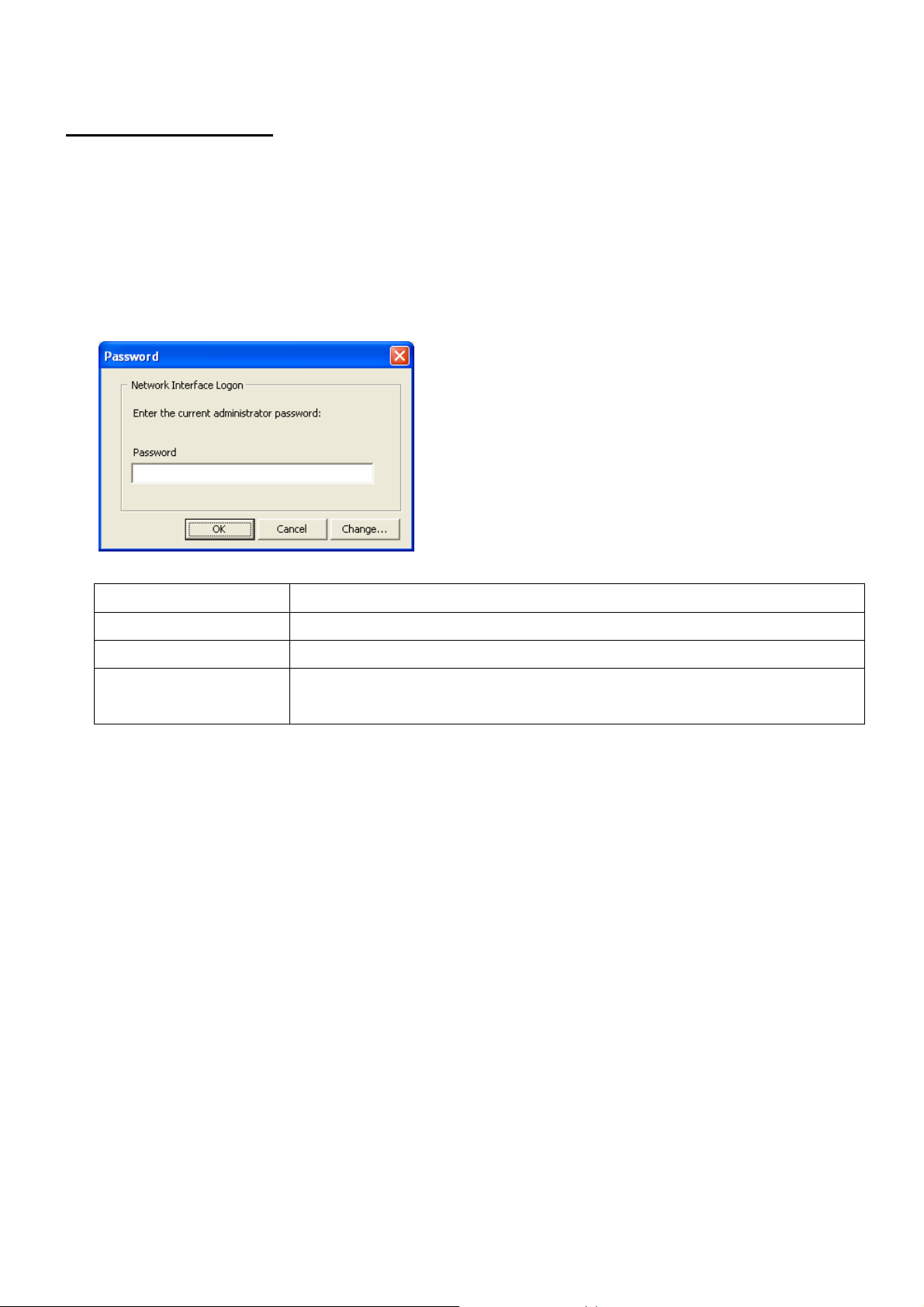
2.The Password dialog box appears.
Item Explanation
Password Enter the password for the selected device. Passwords are case sensitive.
Cancel button The current processing is canceled.
Change button The Administrator Password dialog box appears. Specify the administrator
password for the selected device.
3.Click Change or Batch Password Change in the Password dialog box, and then specify the password
for the selected device.
[Old Password]
Leave it blank if you are setting a password for the first time.
[New Password]
Enter the new password (up to 32 characters). Passwords are case sensitive.
[New Password (again) ]
Enter the password again to confirm.
Note:
- Since the new password becomes effective after the data is sent to the network interface, enter the old
password immediately after changing the p assword.
- If you forget your password, you need to initialize the network interface.
6/25
©SEIKO EPSON CORPORATION 2008-2009. All rights reserved.
Page 7

6. Setup Windows
This section explains in full detail the workings of each setup window.
6.1 Opening screen
You will see the TMNet WinConfig opening window when you launch TMNet WinConfig.
Item Explanation
Tree view
Items
List view
Search button
Launch Browser button
Configuration button
(*1) Selection of COM is also possible by customization.
Clicking Ethernet, Wireless, or USB (*1) brings up information on the network
interfaces connected to the selected network or port.
The list will be sorted in ascending or descending order of the item you have
chosen, such as IP Address, MAC Address, Printer ID, or Model Name. The
display width for each item can be controlled by dragging the right edge of each
item header.
The information on the network devices connected to the interface you have
selected in the Tree view is displayed here. To start configuration, double-click the
network interface you want to configure, or select the network interface and click
the Configuration button.
Updates the List view with the latest information by rescanning the interfaces.
When the IP address is set to something other than the factory default, you can
launch TMNet WebConfig by selecting a network interface and clicking this
button. Normally you do not need to use this button.
Click this button to start configuring a network interface. It opens the Network
Interface Card Properties window.
7/25
©SEIKO EPSON CORPORATION 2008-2009. All rights reserved.
Page 8
6. 2 Menu bar
TMNet WinConfig provides the following menus and sub-menus.
Item Explanation
Device
View Refresh
Tool
Help About TMNet
Configuration
Launch Browser
Exit
Timeout
Search Paths
Search Options
WinConfig
Configures the network interface you have selected.
When the IP address is set to something other than the factory
default, you can launch TMNet WebConfig with this. Normally you do
not need to use this.
Exits TMNet WinConfig.
Updates the List view with the latest information by rescanning the
interfaces.
Opens the Timeout window where you can set the timeout value.
See 6.2.1 Timeout for more information.
Opens the Search Paths window where you can set the paths for
searches.
See 6.2.2 Search Paths for more information.
Opens the Search Options window for TCP/IP and COM where you
can set various search options.
See 6.2.3 Search Options for more information.
Displays the copyright and version information on TMNet WinConfig.
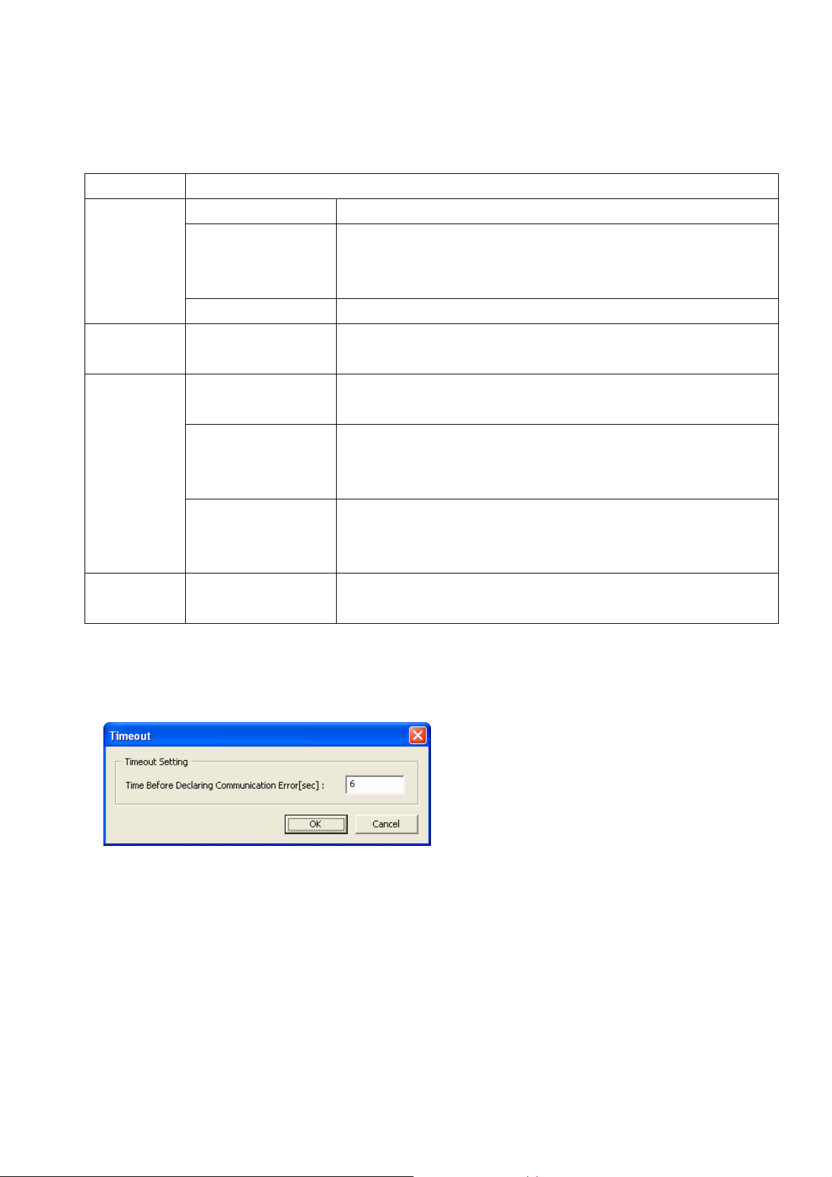
6. 2. 1 Timeout
This window can be opened by selecting Tool and then Timeout.
In this window, you can set the timeout time for communicating with a network interface. A communication
error occurs if this time is exceeded.
The following table explains in detail how this setup window works.
8/25
©SEIKO EPSON CORPORATION 2008-2009. All rights reserved.
Page 9

Item Explanation
Time Before
Declaring
Communication
Error
OK button Click the OK button to save your settings.
Cancel button Click the Cancel button to discard any changes.
6. 2. 2 Search Paths
This window can be opened by selecting Tool and then Search Paths.
Specify (between 6 and 120 seconds) the timeout time at which a communication
error is triggered. The default value is 6 seconds. Normally you need not change
this value.
Specify a larger value for this if you see a communication error after you have
changed the search options so that other network segments are to be searched as
well.
A larger timeout value means more time required to search for network interfaces.
In this window, you ca n select the protocols that are used for searching for network interfaces.
The following table explains in detail how this setup window works.
Item Explanation
Search Setting Select the preferred protocols used to search for network interfaces.
TMNet WinConfig will use these protocols when it searches for network interfaces.
OK button Click the OK button to save new settings.
Cancel button Click the Cancel button to discard any changes.
9/25
©SEIKO EPSON CORPORATION 2008-2009. All rights reserved.
Page 10

6. 2. 3 Search Options
6. 2. 3. 1 Search Options-IP
This window can be opened by selecting Tool, Search Options, and then IP.
TMNet WinConfig can search for TCP/IP-managed network interfaces that are located outside your local
network. It will scan the network segment matched by the network address specified here for any network
interfaces that are used.
The settings you make here will take effect when you choose Refresh from the View menu or restart
TMNet WinConfig.
The following table explains in detail how this setup window works.
10/25
©SEIKO EPSON CORPORATION 2008-2009. All rights reserved.
Page 11

Item Explanation
Search Specified
Address
IP Address
Select this check box if you want TMNet WinConfig to search for network interfaces
located outside your local network (beyond the router). Do not select it unless you
intend to configure network interfaces in other segments. It would cause searches
to take more time.
Enter the network address for the segment you want to search. Use an address with
all bits in the host ID portion set to 0.
If, for example, the network segment you are interested in has the subnet mask
255.255.255.0 (Class C) and the network interface has the IP address 192.168.0.5,
then enter 192.168.0.0 here.
If you try to specify an address whose host ID portion does not have all bits set to 0,
a message that looks like the following appears:
“The network address 192.168.0.5 that you entered will be added to the list as
192.168.0.0. Add this address?”
Click OK, and the corrected address (with all bits in the host ID portion set to 0) will
be added to the list.
If the corrected address is already on the list, a message like the following is
displayed and the address will not be added:
“The network address 192.168.0.5 that you entered will be added to the list as
192.168.0.0. This address is already registered.”
Subnet Mask
List box Clicking the Add button will add to the list the network address and subnet mask
Add button
Delete button
OK button Click the OK button to save new settings.
Cancel button Click the Cancel button to discard any changes.
Enter here the subnet mask for the segment you want to search.
you have entered.
Adds the network address and subnet mask to the list. You can add up to 20 pairs of
addresses.
Removes the selected address pair from the list.
11/25
©SEIKO EPSON CORPORATION 2008-2009. All rights reserved.
Page 12

6. 2. 3. 2 Search Options-COM
This window can be opened by selecting Tool, Search Options, and then COM.
TMNet WinConfig can search for network interfaces managed by the COM port. Set up a COM port here,
and the system will search for network interfaces connected to your computer via that COM port. The
settings you make here will take effect when you choose Refresh from the View menu or restart TMNet
WinConfig.
The following table explains in detail how this setup window works.
Item Explanation
Port
BaudRate
Parity
Flow Control
OK button Click the OK button to save new settings.
Cancel button Click the Cancel button to discard any changes.
Select a COM port for searching.
Only the ports that are available are listed here.
Choose a communication speed for the selected COM port.
Choose a parity setting from None, Odd, or Even.
Choose a flow control method from None, RTS/CTS, or DTR/DSR
12/25
©SEIKO EPSON CORPORATION 2008-2009. All rights reserved.
Page 13

6. 3 Printer menu
This window can be opened by selecting Device, Configuration, and then the Printer tab.
The Printer menu displays information on printers that have network interfaces mounted on them.
The following table explains in detail how this setup window works.
Item Explanation
Location
Model Name
Printer ID
Printer Type
ROM Version
Enter the physical location of the printer (with 0 to 255 ASCII characters). Character
numbers that can be used varies depending on the network system you use.
The model name of the printer on which a network interface is installed is displayed
here. Grayed out if the network interface is not supported by the system.
You can use 0 to 128 ASCII characters.
Character numbers that can be used varies depending on the network system you
use.
The model ID of the printer is displayed, in decimal.
This item is not displayed if the network interface is not supported by the system.
The type ID of the printer is displayed, in decimal.
This item is not displayed if the network interface is not supported by the system.
The ROM version ID of the printer is displayed, in decimal.
This item is not displayed if the network interface is not supported by the system.
OK button Click the OK button to save new settings. The password is required.
Cancel button Click the Cancel button to discard any changes.
13/25
©SEIKO EPSON CORPORATION 2008-2009. All rights reserved.
Page 14

6. 4 Print Server menu
This menu can be opened by selecting Device, Configuration, and then the Print Server tab.
The Print Server menu displays information on the network interface card mounted on the print server.
Wireless Information appears only for a wireless network interface card.
The following table explains in detail how this menu works.
Item Explanation
Administrator Name
MAC Address
Hardware Version
Software Version
Return to Default button
Enter the administrator name of the printer .
You can use 0 to 255 ASCII characters.
Character numbers that can be used varies depending on the network system you
use
It is grayed out and does not accept input if the network interface is not supported
by the system.
The MAC address of the network interface is displayed.
The hardware version of the network interface is displayed.
The software version of the network interface is displayed.
Reverts to the factory default settings. The password is required.
14/25
©SEIKO EPSON CORPORATION 2008-2009. All rights reserved.
Page 15

Item Explanation
Communication Mode
SSID
Channel
Transmission Rate
Associated Access
Point (MAC Address)
Signal Condition
Refresh button
OK button Click the OK button to save new settings. The password is required.
Cancel button Click the Cancel button to discard any changes.
The communication mode of the wireless network is displayed.
The Service Set Identifier (SSID) of the access point or wireless LAN is displayed.
The channel used for wireless communication is displayed.
The transmission speed for the wireless network is displayed.
The MAC address of the access point used for wireless LAN in the Infrastructure
mode is displayed. If the Ad Hoc mode is used, this item does not appear.
The condition of the radio waves is displayed.
Three antennas: Excellent
Two antennas: Good
One antennas: Poor
None: No connection
Question mark: Unknown.
Make an inquiry to the network I/F and updates the content with the latest wirele ss
information.
15/25
©SEIKO EPSON CORPORATION 2008-2009. All rights reserved.
Page 16

6. 5 TCP/IP menu
This menu can be opened by selecting Device, Configuration, and then the TCP/IP tab.
The TCP/IP menu helps you configure the TCP/IP settings on the network interface.
The following table explains in detail how this menu works.
Item Explanation
Manual, Automatic,
DHCP, BOOTP, RARP
Set using Automatic
Private IP Addressing
(APIPA)
Set using PING
Select the method for assigning an IP address. The choices here vary depending
on the network interface.
If you select Automatic, a different IP address is assigned to the network
interface every time you turn on the device. If you do not have a DHCP server with
DNS support, select Manual here and specify an IP address directly.
If you select Automatic when DHCP, BOOTP, and RARP are all grayed out,
TMNet WinConfig will obtain an IP address from the server by automatically
determining the server type.
If this check box is selected, a private IP address is automatically assigned to the
network interface by APIPA (Automatic Private IP Addressing) when there is no
DHCP server on the network or there is no response from the DHCP server. The
private IP address will be in the range of 169.254.0.1 to 169.254.255.254.
This check box is grayed out if the IP Address Setting is set with Manual or
APIPA is not supported.
Select this check box when setting an IP address using the ARP/PING command.
16/25
©SEIKO EPSON CORPORATION 2008-2009. All rights reserved.
Page 17

Item Explanation
IP Address
Subnet Mask
Default Gateway
OK button Click the OK button to save new settings. The password is required.
Cancel button Click the Cancel button to discard any changes.
Enter an IP address for the network interface. Make sure that the IP address you
choose is unique and does not conflict with the address of any other device on the
network.
Due to the product specifications, the factory default IP address
(192.168.192.168) assigned to the device cannot be used on the network. Make
sure that you assign a valid IP address to the network interface.
Enter the subnet mask of the network.
Enter the IP address of your gateway, whether it is a server or a router.
6. 6 Wireless menu
This menu can be opened by selecting Device, Configuration, and then the Wireless tab.
The Wireless menu helps you configure the wireless settings on the network interface. This setup menu only
appears for a wireless network interface.
17/25
©SEIKO EPSON CORPORATION 2008-2009. All rights reserved.
Page 18

Item Explanation
Communication Mode
SSID
Channel
WEP
Input using hex
Active WEP Key
WEP Key Length
WEP Key (1 to 4)
Select the wireless LAN mode.
Enter the SSID for the wireless LAN group to connect to. It is initially set to
EpsonNetIBSS, but make sure you change this value.
It only accepts ASCII, up to 32 characters.
You can enter either name of ESS ID and SSID here.
Enter the ESS ID of the access point if the wireless LAN group operates in the
Infrastructure mode.
Only available when the wireless LAN operates in the Ad Hoc mode. Specify the
same channel as used on the wireless LAN.
Select this check box when using WEP Keys for encryption.
Select this check box when entering WEP Keys in hexadecimal.
The default is to enter them in ASCII.
When more than one WEP Keys are specified, choose one as the active key.
Select the length of a WEP Key. This indicates the strength of the encryption.
Enter WEP Keys
The exact format for a WEP Key varies according to the values in the fields Input
using hex and WEP Key Length.
For a 64-bit (40-bit) WEP Key, use 10 digits in hexadecimal or 5 characters in
ASCII.
For a 128-bit (104-bit) WEP Key, use 26 digits in hexadecimal or 13 characters in
ASCII.
The WEP Keys you enter here will all become hidden from view after the network
interface is configured. Do not forget your WEP Keys.
WPA/WPA2
PSK (Pre-shared Key)
Advanced Settings...
button
OK button Click the OK button to save new settings. The password is required.
Cancel button Click the Cancel button to discard any changes.
Select this check box when using WPA/WPA2 with a PSK (Pre-shared Key) for
encryption.
Grayed out when your network interface does not support WPA/WPA2.
Enter the PSK (Pre-shared Key) password (with 8 to 63 ASCII characters) to be
used for WPA/WPA2 authentication.
Click this button if you want to proceed to make advanced settings on the wireless
LAN. Normally you do not need to change them. Do it only if you need to improve
wireless communication performance.
See 6.6.1 Wireless Advanced Settings dialog box for more information.
18/25
©SEIKO EPSON CORPORATION 2008-2009. All rights reserved.
Page 19

6. 6. 1 Wireless Advanced Settings dialog box
This dialog box can be opened by selecting Tools and then Timeout settings.
The Wireless Advanced Settings menu helps you set the detail of wireless LAN setting for the network I/F.
Items in the dialog box may be grayed out if they are not supported by your network interface.
Item Explanation
Transmission Rate
Authentication
Method
Enable the power
management
function
Normally use Auto to communicate with the best speed for your environment. The
system will try a slower rate if conditions deteriorate, affecting the communication at
the current rate.
Select a fixed transmission speed in some reasons: 1 Mbps, 2 Mbps, 5.5 Mbps, or
11 Mbps.
Shared Key or Open System. Initially, Shared Key is selected if WEP is enabled in
the Wireless menu (see 6.6), and Open System if not. You can change this to
reflect your wireless network environment.
Select this check box to enable the power management to conserve electricity. If
enabled, the batteries will last longer.
19/25
©SEIKO EPSON CORPORATION 2008-2009. All rights reserved.
Page 20

Item Explanation
RTS/CTS Threshold
(0-2347)
Enable the roaming
function
AP Density
Set fragment
threshold
Specify the threshold (number of bytes) between 0 and 2347. Data with its frame
size larger than this value performs the RTS/CTS handshake. If you are not
suffering from performance loss caused by some hidden terminals, you can specify
a larger value for this to improve overall throughput. The initial value may vary
depending on the kind of network interface used. The value of 0 for this means the
RTS/CTS handshake control is always on.
Find the best threshold value for your environment by monitoring your wireless LAN
performance.
Select this check box to enable roaming among multiple access points.
Select Medium or High if your node switches access points too frequently due to
the high density of access points in your area. This reduces noise or interference
and minimizes the frequency with which roaming takes place.
If a data frame fails to reach its destination, it nee ds to be re-transmitted. Select this
check box if you want the data to be broken into smaller chunks when they are
transmitted. This improves performance when there is high traffic on the wireless
LAN. You specify the packet size in the Fragment Threshold field.
If you clear this check box, a data frame is transmitted as a whole.
Fragment Threshold
(256-2346)
OK button Click the OK button to save new settings.
Cancel button Click the Cancel button to discard any changes.
Specify the threshold value (in bytes, between 256 and 2346) for fragmentation to
occur. Data is transmitted in pieces so that its size does not exceed this value. It
defaults to 2346 bytes.
20/25
©SEIKO EPSON CORPORATION 2008-2009. All rights reserved.
Page 21

7. Troubleshooting
Cannot configure the network interface or cannot print from the network.
Step 1
First, check to see if you can print out the Network Status Sheet. If you can print out the sheet, make sure
that there are no errors in the settings that are printed on the sheet.
Step 2
Verify that the hub and the cables are all working properly. Check to see if the lamp on the hub for the port
the device is connected to is either lit or flashing on and off. If it is dead, confirm the following:
z Try connecting the device to another port to see if the lamp lights up.
z Try connecting the device to another hub.
z Try different LAN cables.
If all these failed, there is a possibility that your network interface is damaged. Consult the operation manual
for the device.
Step 3
If your network interface is running on TCP/IP, check to see if it has a valid IP address assigned. The default
IP address 192.168.192.168 initially set to the device cannot be used on the network due to the product
specifications. Choose a different IP address as your operational environment requires.
Step 4
Make sure that you have not selected Block in the Windows Securi ty Warning window or in a similar warnin g
window displayed by a commercial security application. If you have, TMNet WinConfig cannot communicate
with other devices on the network. To enable communication, register this software as an exception in the
security settings for the Windows Firewall or other security applications that you are using.
Some commercial applications, even after you have followed the steps above, do not allow this software to
send data on the network. If this is the case, try turning off the blocking altogether in those applications'
settings or try quitting the applications before using TMNet WinConfig.
Note that the action written above is accompanied by risk. Make sure that turn on the blocking or restart the
security application after setting network interface.
21/25
©SEIKO EPSON CORPORATION 2008-2009. All rights reserved.
Page 22

In the opening window of TMNet WinConfig, the Model Name field is empty and the IP Address says
NONE.
Step 1
This occurs if you have not changed the IP address of your network interface. You can still configure your
network interface by looking at its MAC address. Find out the MAC address on the Network Status Sheet if
you have a printer connected to the network. The opening window will display the correct IP address after
you complete the configuration.
Step 2
Update the window by choosing Refresh from the View menu.
See 6.2 Menu bar for more details.
Step 3
Select Tool and then Timeout, and increase the timeout time in the Timeout setup window that appears.
Note that doing so may slow down TMNet WinConfig because it would need more time for searching. See
6.2.1 Timeout for more details.
The IP address changes to a different number when you haven't touched it.
Step 1
In the TCP/IP setup menu, select Manual for IP Address Setting and enter an IP address directly.
Step 2
If your DHCP server does not support dynamic DNS but you need to select Automatic in the TCP/IP setup
menu, decide in what order you turn on the network devices or leave them on at all time.
It takes a few minutes to start TMNet WinConfig.
If you have Novell client services or a Microsoft NetWare client installed on your computer, it may affect the
performance of TMNet WinConfig because they use IPX for dialup network. Stop using them if you do not
need them.
The wireless network interface server does not appear in the List view.
Step 1
Make sure that the wireless network interface is switched on.
Step 2
Make sure that the wireless network interface is properly connected to the device.
Step 3
Make sure that the network settings on the network interface, such as the WEP Key, SSID, and the
authentication method, all reflect the settings on the wireless LAN.
Step 4
Check your network environment to see if there isn't any interference from other wireless devices, if stations
aren't placed too wide apart, or if there aren't any obstacles in the area interfering with transmissions.
22/25
©SEIKO EPSON CORPORATION 2008-2009. All rights reserved.
Page 23

The WEP Keys and the WPA/WPA you have entered are not displayed on the screen.
For security reasons, these keys become hidden from view once you enter them. Do not forget what they are.
Bad reception of radio signals in the Ad Hoc mode.
Try using a different channel (by at least 5) than the one used on the nearest wireless LAN group.
The wireless communication speed is very slow.
Step 1
Try increasing the RTS/CTS Threshold value so that there is less interference caused by some hidden
terminals. Refer to 6.6.1 Wireless Advanced Settings dialog box for more details.
Step 2
For a poor wireless environment, specify a lower value for the Fragment Threshold (6.6.1).
Step 3
Increase the Transmission Rate as required. Note that the higher the rate, the shorter the range will be.
The wireless network interface does not roam from one access point to another.
Try changing the AP Density value in the Wireless Advanced Settings dialog box.
Installation of TMNet WinConfig Ver.3 failed with the error message “Old version is detected. Please
uninstall the old TMNet WinConfig, and install TMNet WinConfig Ver.3.”
If you already have Ver.1.00 or Ver.2.00 of TMNet WinConfig installed on your computer, you cannot install
TMNet WinConfig Ver.3 on the same computer. Uninstall the older version before installing this version.
“Some functions of this program are blocked by the Windows Firewall. To enable it, you need to register
TMNet WinConfig to exceptions for the Windows Firewall, and restart TMNet WinConfig. See the TMNet
WinConfig User’s Guide for how to register.” is displayed, and the printer is not searched.
Follow the steps below to register this program to exception or confirm if it is registered.
1. Display the Windows Firewall screen.
For Windows XP: [Control Panel] – [Windows Firewall]
For Window Vista: [Control Panel] – [Security] – [Allow a program through Windo ws Firewall]
For Windows 7: [Control Panel] – [System and Security] – [Allow a program through Windows
Firewall]
23/25
©SEIKO EPSON CORPORATION 2008-2009. All rights reserved.
Page 24

2. In the General tab, make sure the Windows Firewall is set to ON, and the checkbox of “Don’t allow
exceptions” is not checked. If it is checked, uncheck it.
3. Click the Exceptions tab, and make sure there is “TMNet WinConfig” in the program list.
If there is not, click the Add Program button, and add TMNet WinConfig to the list.
24/25
©SEIKO EPSON CORPORATION 2008-2009. All rights reserved.
Page 25

4. Make sure the checkbox of “TMNet WinConfig” in the list is checked, and click the OK button.
5. Restart TMNet WinConfig.
25/25
©SEIKO EPSON CORPORATION 2008-2009. All rights reserved.
 Loading...