

Page 1
®
SERVICE MANUAL
SERVICE MANUAL
SERVICE MANUALSERVICE MANUAL
Color Flat Bed Scanner
EPSON GT-10000
SESC99005
Page 2
Notice:
n
All rights reserved. No part of this manual may be reproduced, stored in a retrieval system, or transmitted in any form or by any means,
electronic, mechanical, photocopying, recording, or otherwise, without the prior written permission of SEIKO EPSON CORPORATION.
n
The contents of this manual are subject to change without notice.
n
All effort have been made to ensure the accuracy of the contents of this manual. However, should any errors be detected, SEIKO EPSON
would greatly appreciate being informed of them.
n
The above not withstanding SEIKO EPSON CORPORATION can assume no responsibility for any errors in this manual or the consequences
thereof.
EPSON is a registered trademark of SEIKO EPSON CORPORATION.
General Notice: Other product names used herein are for identification purpose only and may be trademarks or registered trademarks of their
respective owners. EPSON disclaims any and all rights in those marks.
Copyright © 1999 SEIKO EPSON CORPORATION. Printed in Japan.
Page 3
PRECAUTIONS
Precautionary notations throughout the text are categorized relative to 1)Personal injury and 2) damage to equipment.
DANGER
WARNING
The precautionary measures itemized below should always be observed when performing repair/maintenance procedures.
Signals a precaution which, if ignored, could result in serious or fatal personal injury. Great caution should be exercised in
performing procedures preceded by DANGER Headings.
Signals a precaution which, if ignored, could result in damage to equipment.
DANGER
1. ALWAYS DISCONNECT THE PRODUCT FROM THE POWER SOURCE AND PERIPHERAL DEVICES PERFORMING ANY MAINTENANCE
OR REPAIR PROCEDURES.
2. NOWORK SHOULD BE PERFORMED ON THE UNIT BY PERSONS UNFAMILIAR WITH BASIC SAFETY MEASURES AS DICTATED FOR
ALL ELECTRONICS TECHNICIANS IN THEIR LINE OF WORK.
3. WHEN PERFORMING TESTING AS DICTATED WITHIN THIS MANUAL, DO NOT CONNECT THE UNIT TO A POWER SOURCE UNTIL
INSTRUCTED TO DO SO. WHEN THE POWER SUPPLY CABLE MUST BE CONNECTED, USE EXTREME CAUTION IN WORKING ON
POWER SUPPLY AND OTHER ELECTRONIC COMPONENTS.
WARNING
1. REPAIRS ON EPSON PRODUCT SHOULD BE PERFORMED ONLY BY AN EPSON CERTIFIED REPAIR TECHNICIAN.
2. MAKE CERTAIN THAT THE SOURCE VOLTAGES IS THE SAME AS THE RATED VOLTAGE, LISTED ON THE SERIAL NUMBER/RATING
PLATE. IF THE EPSON PRODUCT HAS A PRIMARY AC RATING DIFFERENT FROM AVAILABLE POWER SOURCE, DO NOT CONNECT IT
TO THE POWER SOURCE.
3. ALWAYS VERIFY THAT THE EPSON PRODUCT HAS BEEN DISCONNECTED FROM THE POWER SOURCE BEFORE REMOVING OR
REPLACING PRINTED CIRCUIT BOARDS AND/OR INDIVIDUAL CHIPS.
4. IN ORDER TO PROTECT SENSITIVE MICROPROCESSORS AND CIRCUITRY, USE STATIC DISCHARGE EQUIPMENT, SUCH AS ANTI-
STATIC WRIST STRAPS, WHEN ACCESSING INTERNAL COMPONENTS.
5. REPLACE MALFUNCTIONING COMPONENTS ONLY WITH THOSE COMPONENTS BY THE MANUFACTURE; INTRODUCTION OF
SECOND-SOURCE ICs OR OTHER NONAPPROVED COMPONENTS MAY DAMAGE THE PRODUCT AND VOID ANY APPLICABLE EPSON
WARRANTY.
Page 4
PREFACE
This manual describes basic functions, theory of electrical and mechanical operations, maintenance and repair procedures of GT-10000. The
instructions and procedures included herein are intended for the experienced repair technicians, and attention should be given to the precautions on
the preceding page. The chapters are organized as follows:
CHAPTER 1. PRODUCT OUTLINE
Provides a general overview and specifications of the product.
CHAPTER 2. OPERATING PRINCIPLES
Describes the theory of electrical and mechanical operations of the product.
CHAPTER 3. TROUBLESHOOTING
Provides the step-by-step procedures for troubleshooting.
CHAPTER 4. DISASSEMBLY & ASSEMBLY
Describes the step-by-step procedures for disassembling and assembling the
product.
CHAPTER 5. ADJUSTMENTS
Provides Epson-approved methods for adjustment.
CHAPTER 6. MAINTENANCE
Provides preventive maintenance procedures and the lists of Epson-approved
lubricants and adhesives required for servicing the product.
CHAPTER 7. APPENDIX
Provides the following additional information for reference:
• Connector Pin Assignment
• Circuit Board Component Layout
• Circuit Board Diagram
• Exploded Diagrams & ASP List
Page 5
Revision Status
Revision Issued Date Description
A June 14, 1999 First Release
Page 6
EPSON GT-10000 Revision A
Table of Contents
CHAPTER 1 PRODUCT OUTLINE
Overview ........................................................................................................ 9
Specifications .............................................................................................. 10
Basics ..................................................................................................... 10
Image Handling Specifications .......... ..................................................... 10
Electrical Specifications .................................................... ...................... 11
Safety, EMC, EPA .................................................................................. 11
Resistance to Electric Noi se ................................................................... 11
Environmental Specifications ................................................................. 11
Reliability ................................................................................................ 11
Operating Conditions .............................................................................. 11
Original Document Condition ................................................................. 12
Physical Dimensions and Weight ........................................................... 12
Interface Specifications ............................................................................... 13
SCSI Interface ........................................................................................ 13
Basic Specifications ........................................................................... 13
Functions ............................................................................................ 13
SCSI Electrical Specifications ............................................................ 13
Connectors ... ...................................................................................... 13
Terminator .......................................................................................... 13
SCSI ID Setting .................................................................................. 13
Commands ......................................................................................... 14
Status ................................................................................................. 15
Display Messages .............................................................................. 15
Connector pin arrangement .................... ............................................ 16
IEEE 1394 Serial Bus Interface *Option* ............................................... 16
Control Code ............................................................................................... 17
Operation Specifications .............................................................................. 18
Buttons and Sw itches .............. ............................................................... 18
LED Specifications ................................................................................. 19
Switch Setting ......................................................................................... 19
Error Indication ....................................................................................... 20
Available Scan Area ............................................................................... 20
Transportation Screw ............................................................................. 21
CHAPTER 2 OPERATING PRINCIPLES
General Descript i on .... . .. .. .. . .. .. . .. .. .. . .. .. .. . .. .. .. . .. .. . .. .. .. . .. .. .. . .. .. .. . .. .. . .. .. .. . .. .. .. . .. 23
Mechanical Operation of the Scan ner ..... .. .. . .. .. . .. .. .. . .. .. .. . .. .. .. . .. .. . .. .. .. . .. .. .. . .. 24
Electrical Circuit Operations ........................................................................ 25
Control Circuit Operation ........................................................................ 25
Power Supply Circuit Operation ............................................................. 26
CHAPTER 3 TROUBLESHOOTING
Overview ..................................................................................................... 29
Errors and Causes of Errors .................................................................. 29
Troubleshooting ..................................................................................... 30
Test Points ......................................................................................... 30
Troubleshooting Other Errors ............................................................. 30
Troubleshooti ng Circui t B oard E rrors .......... . .. .... . .. .. .. ... .. .. . .. ... .. .. .. ... .. .. . .. 35
Power S upply B oard (B054 PS H B oard) ..... .. .. . .. .... . .. .. .. ... .. . .. .... . .. .. .. ... 35
Control Circuit Board (B093M AIN Board) ........................................... 35
CHAPTER 4 DISASSEMBLY & ASSEMBLY
Overview ..................................................................................................... 37
Tools ....... .. . .. .. . .. .. .. . .. .. .. . .. .. . .. .. .. . .. .. .. . .. .. .. . .. .. ....... . .. .. .. . .. .. .. . .. .. . .. .. .. . .. .. .. ... 37
Screws ................................................................................................... 38
Disa ss embly P rocedures . .. . .. .. . .. .. .. ....... . .. .. .. . .. .. . .. .. .. . .. .. .. . .. .. .. . .. .. ....... . .. .. .. . .. 40
Document Cover Unit Removal .............................................................. 41
Electrical Circuit Removal ...................................................................... 41
Main Boards Removal ........................................................................ 42
Scanner Body Disassembly ................................................................... 44
Upper Housing Removal .................................................................... 44
Scanner Mechanism Removal ........................................................... 45
Scanner Mechanism Disassembly ......................................................... 46
Panel Board Assembly Removal ........................................................ 46
Sub Board Assembly Removal ........................................................... 47
HP Sensor (CR) Remov al .................................................................. 48
CR Motor Assembly Removal ............................................................ 48
6
Page 7
EPSON GT-10000 Revision A
Glass Frame Assembly Removal ....................................................... 49
Lamp Assembly and Inverter Board Assembly Removal ................... 52
Option Frame Assembly Removal ...................................................... 54
CHAPTER 5 ADJUSTMENTS
Updating Firmware .............. ........................................................................ 56
Preparations Before Updating ................................................................ 56
Updating Firmware ................................... .............................................. 57
Light Correction ........................................................................................... 61
Necessary Tools ..................................................................................... 61
Light Correction Procedure .................................................................... 61
CHAPTER 6 MAINTENANCE
CHAPTER 7 APPENDIX
Connector Pin Assignment .......................................................................... 67
Connector Pin Assignment ..................................................................... 67
Connector Summary .......................................................... .................... 67
Main Board Circuit Signals ................................................................. 68
Circuit Board Component Layout ...... .......................................................... 72
Circuit Diagram ............................................................................................ 74
Exploded Diagrams & ASP List ................................................................... 76
Exploded Diagrams ................................................................................ 76
ASP List .................................................................................................. 79
7
Page 8

PRODUCT OUTLINE
CHAPTER
1
Page 9

EPSON GT-10000 Revision A
1.1 Overview
The EPSON GT-10000 is an business/office A3 size flat-bed type color image
scanner for use wi th Microsoft® Windows®. The main features of the scanner
are:
o
High resolution
Optical resolution is 600 dpi
12 bit in, 8 bit out
o
Wide readable area
Scans up to A3 size originals
o
High-speed scanni ng
A3 portrai t with full color = 4mS/line
o
Option
Auto Document Feeder (same as GT-12000)
o
Network-use software
EPSON TWAIN Pro Network
EPSON Scan Se rver
o
Scan-Navigation button support
The scan button is functional when using the EPSON TWAIN Pro Network
o
Fast SCSI support
Up to 10MB/S in synchronous data transfer mode
o
International Energy Star compliant
o
High-speed seria l interface (planned option for Windows 2000)
IEEE1394 s erial interface standard
o
Quick operation
Xenon-Gas Cold Cathode Fluorescent Lamp does not require warm-up
period (same as GT-12000).
PRODUCT OUTLINE Overview 9
Page 10
EPSON GT-10000 Revision A
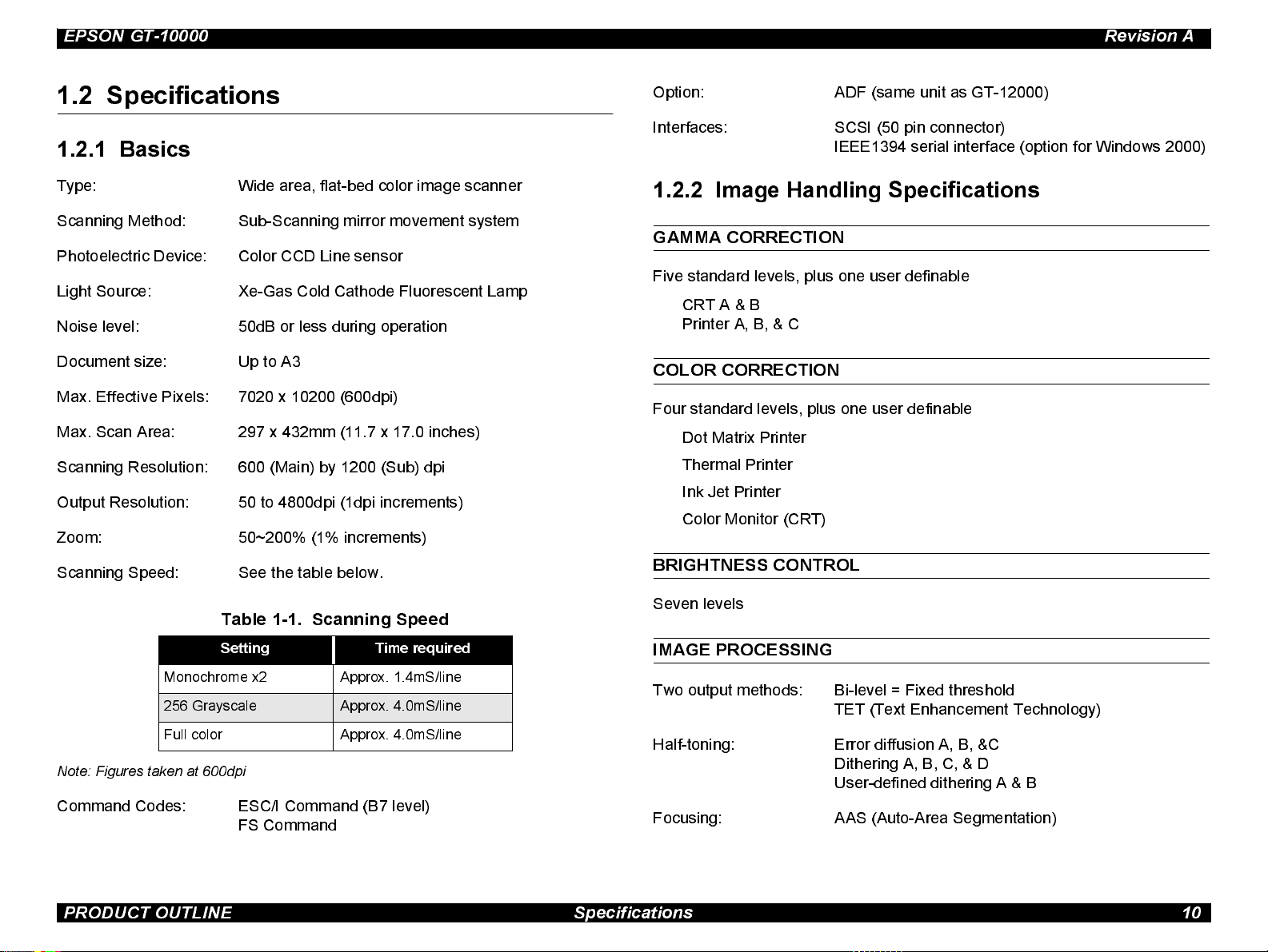
1.2 Specifications
1.2.1 Basics
Type: Wide area, flat-bed color image scanner
Scanning Method: Sub-Scanning mirror movement system
Photoelectric Device: Color CCD Line senso r
Light Source: Xe-Gas Cold Cathode Fluorescent Lamp
Noise level: 50dB or less during operation
Document size: Up to A3
Max. Effective Pixels: 7020 x 10200 (600dpi)
Max. Scan Area: 297 x 432mm (11.7 x 17.0 inches)
Scanning Resolution: 600 (Main) by 1200 (Sub) dpi
Output Resolution: 50 to 4800dpi (1dp i increments)
Zoom: 50~200% (1% i ncrements)
Option: ADF (same unit as GT-12000)
Interfaces: SCSI (50 pi n connector)
IEEE1394 s erial interface (option for Windows 2000)
1.2.2 Image Handling Specifications
GAMMA CORRECTION
Five standard levels, plus one user definable
CRT A & B
Printer A, B, & C
COLOR CORRECTION
Four st andard levels, plus one user definable
Dot Matrix Printer
Thermal Printer
Ink Jet Printer
Color Monitor (CRT)
Scanning Speed: See the table below.
BRIGHTNESS CONTROL
Seven levels
Table 1-1. Scanning Speed
Setting Time required
Monochrome x2 Approx. 1.4mS/line
256 Grayscale Approx. 4.0mS/line
Full color Approx. 4.0mS/line
Note: Figures taken at 600dpi
Command Codes: ESC/I Command (B7 level)
FS Command
IMAGE PROCESSING
Two output methods: Bi-level = Fixed thres hold
TET (Text Enhancement Technology)
Half-toning: Error diffusion A, B, &C
Ditheri ng A, B, C, & D
User-defined dithering A & B
Focusing: AAS (Auto-Area Segmentation)
PRODUCT OUTLINE Specifications 10
Page 11
EPSON GT-10000 Revision A
1.2.3 Electrical Specifications
Power supply voltage: Universal pow er
Rated v oltage = AC100 - 120 V (AC ± 10%)
Rated v oltage = AC220 - 240 V (AC ± 10%)
Rated frequency range: 50~ 60 Hz (49.5 - 60.5 Hz)
Power consumpti on: Approximately 50W (wit hout opti o n)
Approximately 55W (wit h option)
Ω
Insulati on resistance: 10M
Dielectric strength: AC1.2kV rms / minute (between AC line and chassis)
or more (DC 500V between AC line and
chassis)
1.2.4 Safety, EMC, EPA
Safety : UL1950 (UL)
CSA C22.2 NO.950 (CSA)
EN60950 (VDE)
IEC950 (ROSTES T, PSB)
EN61000-3-3
EN 50082-1
IEC 801-2
IEC 801-3
IEC 801-4
EPA: Energy Star Program
1.2.5 Resistance to Electric Noise
Static Electricity: Panel = 10kV
Metallic parts = 7kV (150pF/150
Ω)
1.2.6 Environmental Specifications
Temperature: Operating = 5 to 35°C
When not in use =- -25 to 60°C
Humidity: Operating = 10 to 80% (no condensation)
Storage = 10 to 85% (no condensati on)
EMC: FCC Part15 Subpart B C lass B
1.2.7 Reliability
CSA C108.8 Class B
AS/NZS3548 Class B
CISPR Pub22 Class B
CNS13438 Class B
CE Marking:
Low Voltage Directive 73/23/EEC EN60950
EMC Directive 89/336/EEC EN55022 Class B
EN61000-3-2
PRODUCT OUTLINE Specifications 11
Main unit: MCBF: carriage = 100,000 cycles
Hinge = 25,000 turns
1.2.8 Operating Conditions
Dust: Ordinary office or home conditions.
(Should be kept away from extreme dust.)
Illumination: Operation under di rect sunlight or near strong light
source should be avoided.
Page 12
EPSON GT-10000 Revision A
1.2.9 Original Document Condition
Reflective type: Smooth surface such as a printing and photograph.
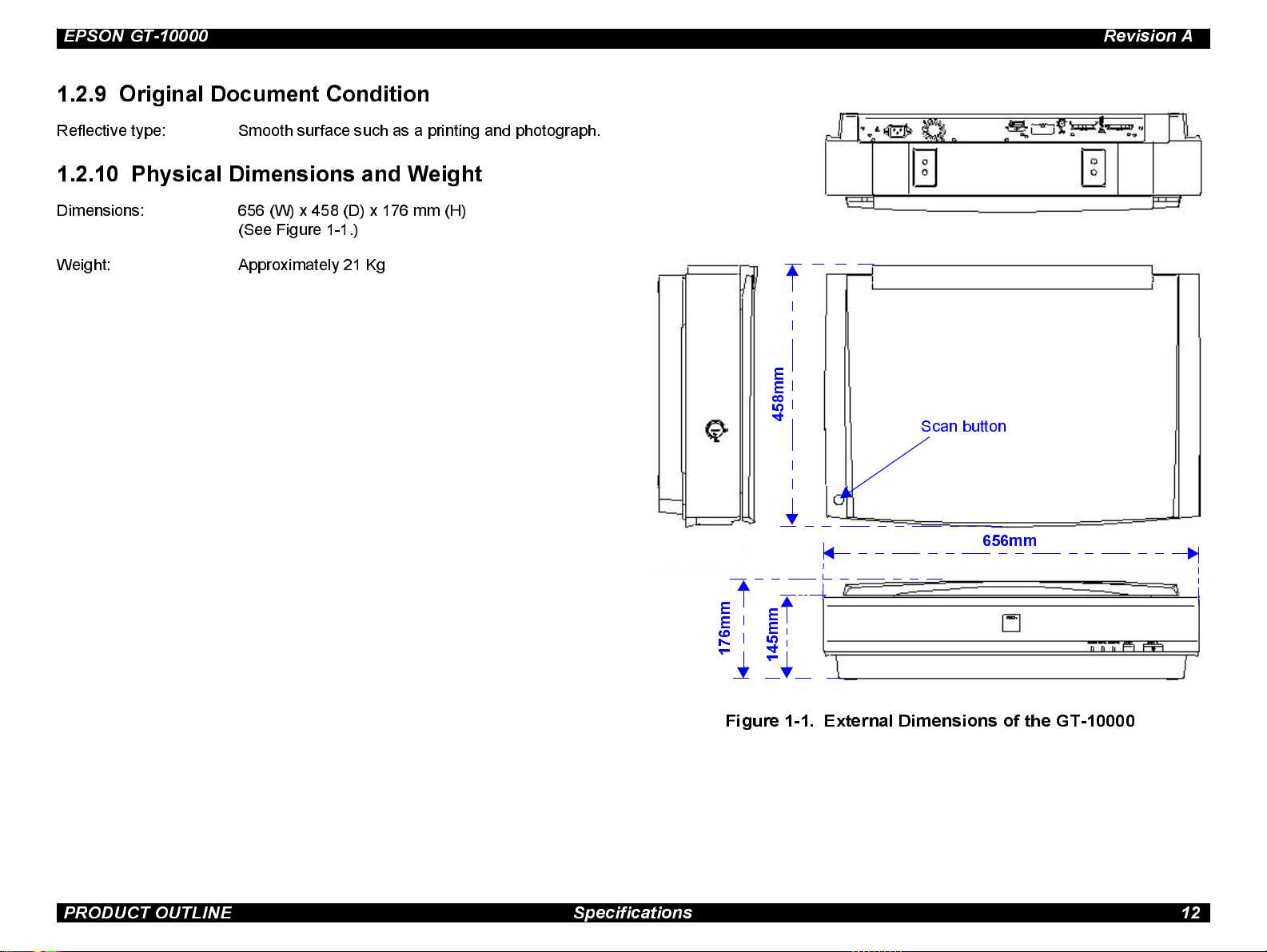
1.2.10 Phy s ica l Dimens ion s and Weig h t
Dimensions : 656 (W) x 458 (D) x 176 mm (H)
(See Fig ure 1 -1.)
Weight: Approximately 21 Kg
m
m
8
5
4
Scan but ton
656mm
m
m
6
7
1
m
m
5
4
1
Figure 1-1. External Dimensions of the GT-10000
PRODUCT OUTLINE Specifications 12
Page 13
EPSON GT-10000 Revision A
1.3 Interface Specifications
This s canner is equipped with two standard SCSI interfaces.
1.3.1 SCSI Interface
1.3.1.1 Basic Specifications
The SCSI interface specifications are described below, any items not included
in the following pages are in conformance with ANSI X3T9.2/375R revision 10L
(SCSI-2).
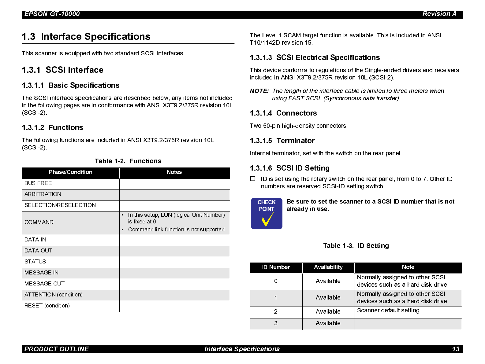
1.3.1.2 Functions
The following functions are included in ANSI X3T9.2/375R revision 10L
(SCSI-2).
Table 1-2. Functions
Phase/Condition Notes
BUS FREE
ARBITRATION
SELECTION/RESELECTION
• In this setup, LUN (logical Unit Number)
COMMAND
DATA IN
DATA OUT
is fixed at 0
• Command link function is not supported
The Level 1 SCAM target function is available. This is included in ANSI
T10/1142D revis ion 15.
1.3.1.3 SCSI Electrical Specifications
This devi ce conforms to regulations of the Single-ended drivers and receivers
included in ANSI X3T9.2/375R revision 10L (SCSI-2).
NOTE:
The length of the interface cable is limited to three meters when
using FAST SCSI. (Synchronous data transfer)
1.3.1.4 Connectors
Two 50-pin high-density connectors
1.3.1.5 Terminator
Internal terminator, set with the switch on the rear panel
1.3.1.6 SCSI ID Setting
o
ID is s et using the rotary switch on the rear panel, from 0 to 7. Other ID
numbers are reserved.SCSI-ID setting switch
CHECK
PO INT
Be sure to set the scanner to a SCSI ID number that is not
already in use.
Table 1-3. ID Setting
STATUS
MESSAGE IN
MESSAGE OUT
ATTENTION (condition)
RESET (condition)
ID Number Availability Note
0Available
1 Available
2Available
3 Available
Normally assigned to other SCSI
devices such as a hard disk drive
Normally assigned to other SCSI
devices such as a hard disk drive
Scanner default setting
PRODUCT OUTLINE Interface Specifications 13
Page 14
EPSON GT-10000 Revision A
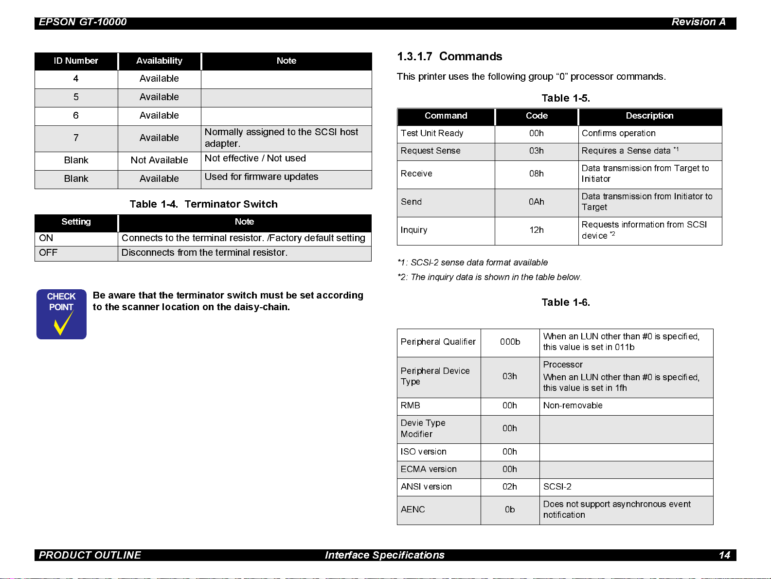
ID Number Availability Note
4 Available
5 Available
6 Available
7 Available
Blank Not Available
Blank Available
Normally assigned to the SCSI host
adapter.
Not effective / Not used
Used for firmware updates
Table 1-4. Terminator Switch
Setting Note
ON Connects to the terminal resi stor. /Factory default setting
OFF Disconnect s from the terminal resistor.
CHECK
PO INT
Be aware that the terminator switch must be set according
to the sc anner location on the daisy-chain.
1.3.1.7 Commands
This printer uses the following group “0” processor commands.
Table 1-5.
Command Code Description
Test Unit Ready 00h Confirms operation
Request Sense 03h Requires a Sense data
Receive 08h
Send 0Ah
Inquiry 12h
*1: SCSI-2 sense data format available
*2: The inquiry data is shown in the table below.
Table 1-6.
Peripheral Qualifier 000b
When an LUN other than #0 is specified,
this value is set in 011b
Data transmission from Target to
Initiator
Data transmission from Initiator to
Target
Requests information from SCSI
*2
device
*1
Peripheral Device
Type
RMB 00h Non-removable
Devie Type
Modifier
ISO version 00h
ECMA version 00h
ANSI version 02h SCSI-2
AENC 0b
03h
00h
Processor
When an LUN other than #0 is specified,
this value is set in 1fh
Does not support asynchronous event
notification
PRODUCT OUTLINE Interface Specifications 14
Page 15
EPSON GT-10000 Revision A
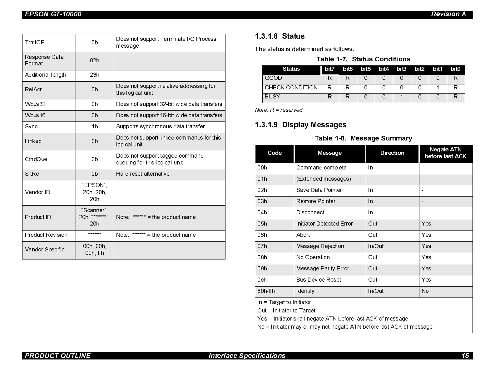
TrmIOP 0b
Respo nse Data
Format
Additional length 23h
RelAdr 0b
Wbu s32 0b Does not support 32-bit wide data transfers
Wbus16 0b Does not support 16-bit wide data transfers
Sync 1b Supports synchronous data transfer
Linked 0b
CmdQue 0b
SftRe 0b Har d res et alternative
Vendor ID
Product ID
02h
“EPSON”,
20h, 20h,
20h
“Scanner”,
20h, “******”,
20h
Does not support Terminate I/O Process
messag e
Doe s not support relative addr essing for
this logical unit
Does not support linked commands for this
logical unit
Does not support tagged command
queuing for this logical unit
Note:: ****** = the product name
1.3.1.8 Status
The stat us is determined as follows.
Ta ble 1- 7 . Status Conditions
Status bit7 bit6 bit5 bit4 bit3 bit2 bit1 bit0
GOOD R R 0 0 0 0 0 R
CHECK CONDITION R R 00001R
BUSY R R 0 0 1 0 0 R
Note: R = reserved
1.3.1.9 Display Messages
Table 1- 8. Messa ge Summary
Code Message Direction
00h Command complete In -
01h (Extended messages)
02h Save Data Pointer In -
03h Restore Pointer In -
04h Disconnect In -
05h Initiator Detected Error Out Yes
Negate ATN
before last ACK
Product Revision “****” Note:: ****** = the product name
Vendor Specific
00h, 00h,
00h, ffh
06h Abort Out Yes
07h Message Rejection In/Out Yes
08h No Operation Out Yes
09h Message Parity Error Out Yes
0ch Bus Device Reset Out Yes
80h-ffh Identify In/Out No
In = Target to Initiator
Out = Initiator to Target
Yes = Initiator shall negate ATN before last ACK of message
No = Initiator may or may not negate ATN before last ACK of message
PRODUCT OUTLINE Interface Specifications 15
Page 16
EPSON GT-10000 Revision A
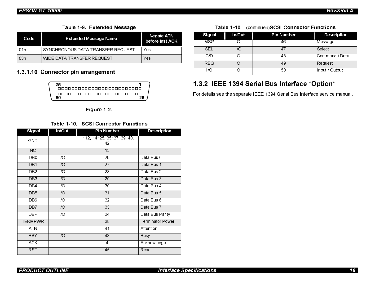
Table 1-9. Extended Message
Code Extended Message Name
01h SYNC HRONOUS DATA TRANSFER REQUEST Ye s
03h WIDE DATA TRANSFER REQUEST Yes
Negate ATN
before last ACK
1.3.1.10 Connector pin arrangement
25
50
Figure 1-2.
Table 1-10. SCSI Connector Functions
Signal In/Out Pin Number Description
GND
NC 13
DB0 I/O 26 Data Bus 0
DB1 I/O 27 Data Bus 1
DB2 I/O 28 Data Bus 2
DB3 I/O 29 Data Bus 3
DB4 I/O 30 Data Bus 4
DB5 I/O 31 Data Bus 5
DB6 I/O 32 Data Bus 6
DB7 I/O 33 Data Bus 7
DBP I/O 34 Data Bus Parity
TERMPWR 38 Terminator Power
ATN I 41 Attention
BSY I/O 43 Busy
ACK I 4 Acknowledge
RST I 45 Reset
1~12, 14~25, 35~37, 39, 40,
42
1
26
Table 1-10.
Signal In/Out Pin Number Description
MSG O 46 Message
SEL I/O 47 Select
C/D O 48 Command / Data
REQ O 49 Request
I/O O 50 Input / Output
(continued)
SCSI Connector Functions
1.3.2 IEEE 1394 Serial Bus Interface *Optio n*
For detai ls see t he sep arate IEE E 1394 S eri al Bus Inte rface serv ice manual.
PRODUCT OUTLINE Interface Specifications 16
Page 17
EPSON GT-10000 Revision A
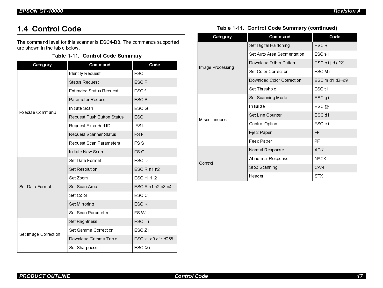
1.4 Control Code
The command level for this scanner is ESC/I-B8. The commands supported
are shown in t he table below.
Table 1-11. Control Code Summary
Category Command Code
Iden tity Request ESC I
Status Request ESC F
Exten d ed Status Request ESC f
Param et er Request ESC S
Initiate Scan ESC G
Execute Command
Request Push Button Status ESC !
Request Extended ID FS I
Request Scanner Status FS F
Request Scan Parameters FS S
Initiate New Scan FS G
Set Data Format ESC D i
Set Resolution ESC R n1 n2
Set Zoom ESC H i1 i2
Table 1-11. Control Code Summary (continued)
Category Command Code
Set Digi t al Half toni ng ESC B i
Set Auto Area Se gment at i on ESC s i
Download Dit her Pat te rn ESC b i j d (j^2)
Image Processing
Set Color Corre ction ESC M i
Download Color Corre cti on ESC m d1 d2~d9
Set Threshol d ESC t i
Set Scanning Mode ESC g i
Ini ti a liz e ESC @
Set Line Counter ESC d i
Miscellaneous
Control Opti on ESC e i
Eject Paper FF
Feed Paper PF
Normal Res ponse ACK
Abnormal Response NACK
Control
Stop Scanning CAN
Header STX
Set Data Format
Set Image Correct ion
Set Scan Area ESC A n1 n2 n3 n4
Set Color ESC C i
Set Mirroring ESC K I
Set Scan Parameter FS W
Set Brightness ESC L i
Set Gamma Correction ESC Z i
Download Gamma Tabl e ESC z i d0 d1~d255
Set Sharpness ESC Q i
PRODUCT OUTLINE Control Code 17
Page 18
EPSON GT-10000 Revision A
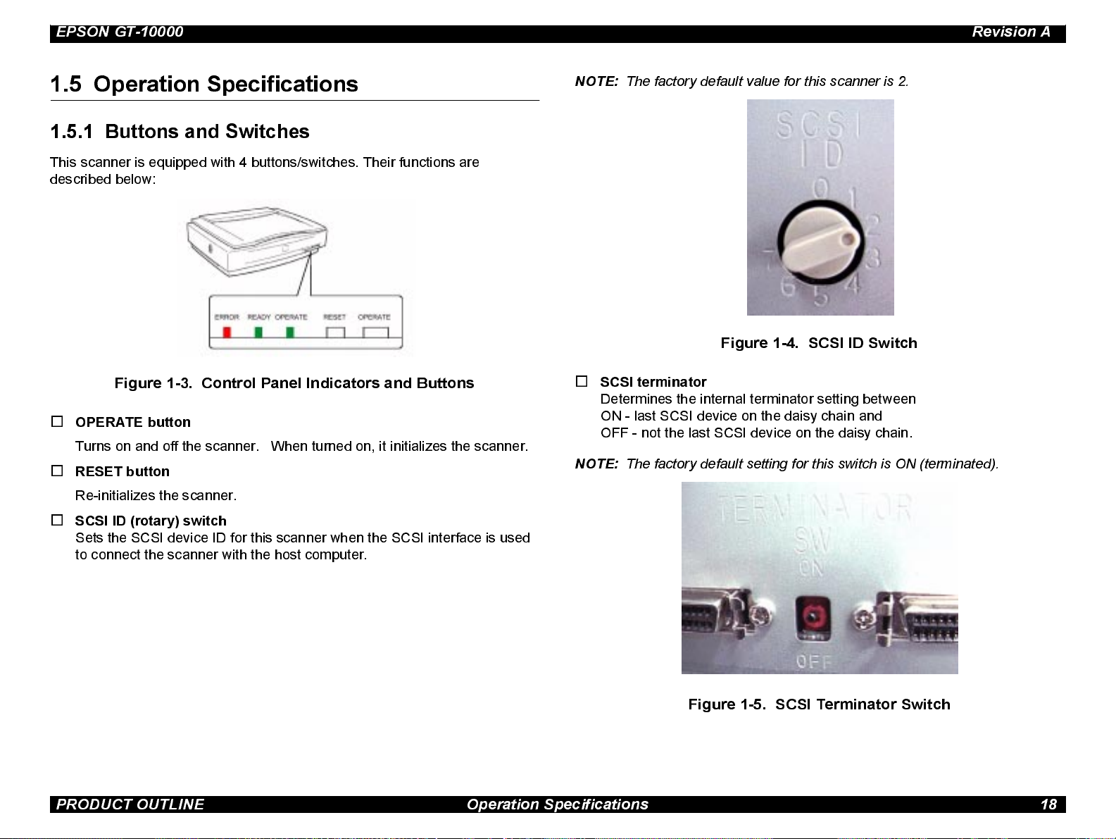
1.5 Operation Specifications
1.5.1 Buttons and Switches
This s canner is equipped with 4 buttons/switches. Their functions are
described below:
Figure 1-3. Control Panel Indicators and Buttons
o
OPERATE button
Turns on and off the scanner. When turned on, it initializes the scanner.
o
RESET button
NOTE:
The factory default value for this scanner is 2.
Figure 1-4. SCSI ID Switch
o
SCSI terminator
Determines the internal terminator setting between
ON - last SCSI device on the daisy chain and
OFF - not the last SCSI device on the daisy chain.
NOTE:
The factory default setting f o r this switch is ON (terminated).
Re-initializes the scanner.
o
SCSI ID (rotary) switch
Sets the SCSI device ID for this scanner when the SCSI interface is used
to connect the scanner with the host computer.
Figure 1-5. SCSI Terminator Switch
PRODUCT OUTLINE Operation Specifications 18
Page 19
EPSON GT-10000 Revision A
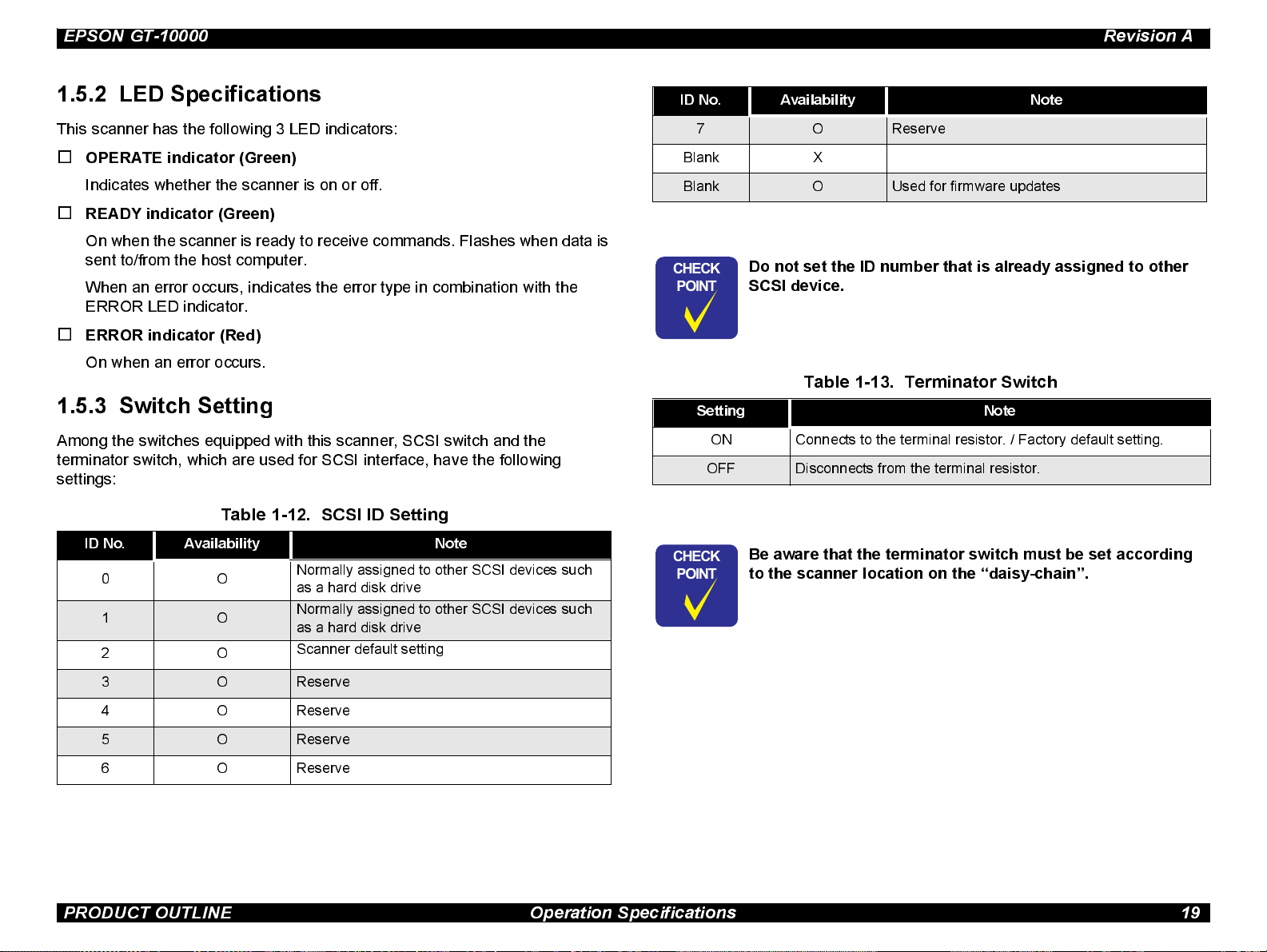
1.5.2 LED Specifications
This s canner has the following 3 LED indicators:
o
OPERATE indicator (Green)
Indicates w hether the scanner is on or off.
o
READY indicator (Green)
On when the scanne r is ready to receive commands. Flashes when data is
sent to/from the host computer.
When an error occurs, indicates the error type in combination with the
ERROR LED indi cator.
o
ERROR indicator (Red )
On when an error occurs.
1.5.3 Switch Setting
Among the switche s equipped with this scanner, SCSI switch and the
terminator s witch, which are used for SCSI interface, have the following
settings:
Table 1-12. SCSI ID Setting
ID No. Availability Note
0O
1 O
2O
Normally assigned to other SCSI devices such
as a hard disk drive
Normally assigned to other SCSI devices such
as a hard disk drive
Scanner default setting
ID No. Availability Note
7 O Reserve
Blank X
Blank O Used for firmware updates
CHECK
PO INT
Do not set the ID number that is already assigned to other
SCSI device.
Table 1-13. Terminator Switch
Setting Note
ON Connects to the terminal resistor. / Factory default setting.
OFF Disconnects from the terminal resistor.
CHECK
PO INT
Be aware that the terminator switch m ust be set according
to the scan ner location on the “daisy-chain”.
3 O Reserve
4 O Reserve
5 O Reserve
6 O Reserve
PRODUCT OUTLINE Operation Specifications 19
Page 20
EPSON GT-10000 Revision A
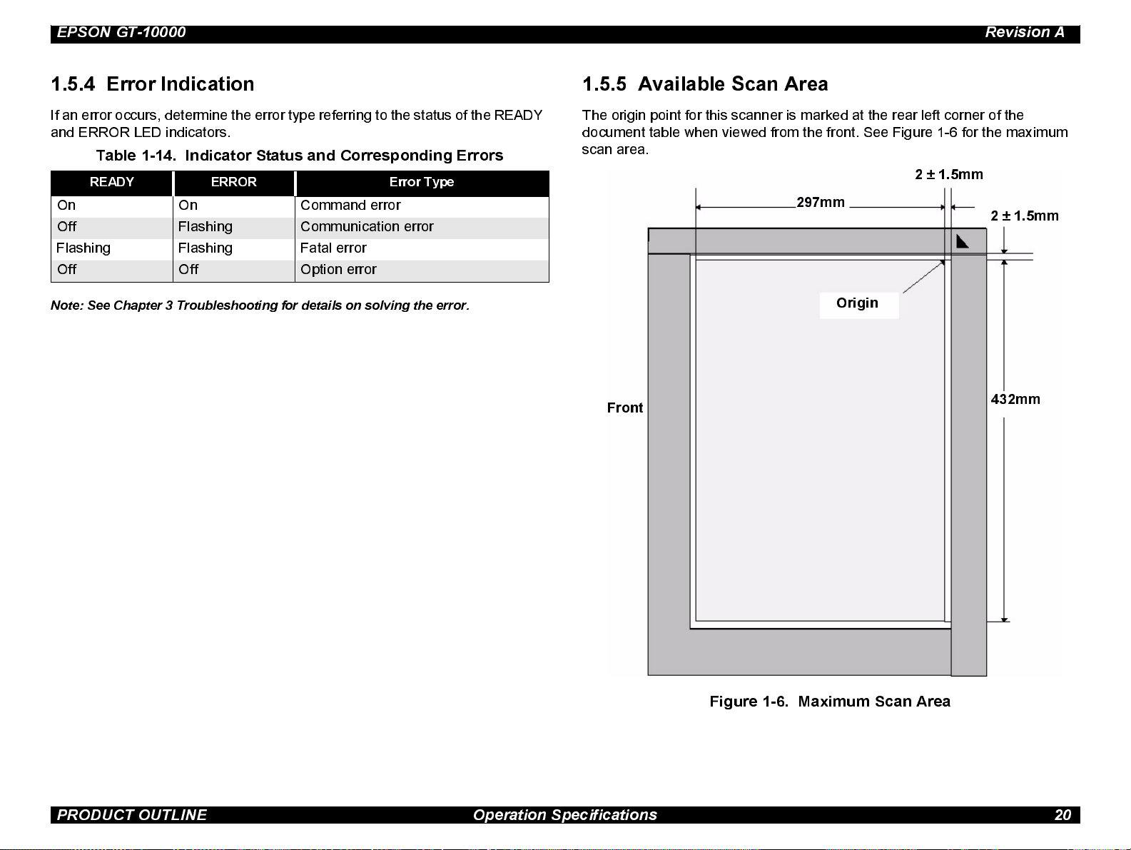
1.5.4 Error Indication
If an error occurs, determine the error type referring to the status of the READY
and ERROR LED i ndicators.
Table 1-14. Indicator Status and Corresponding Errors
READY ERROR Error Type
On On Command error
Off Flashing Communication error
Flashin g Flashing Fatal error
Off Off Option error
Note: See Chapter 3 Troubleshooting for details on solving the error.
1.5.5 Available Scan Area
The origi n point for this scanner is marked at the rear left corner o f the
document table when viewed from the front. See Figure 1-6 for the maximum
scan area.
2 ± 1.5mm
297mm
Origin
Front
2 ± 1.5mm
432mm
Figure 1-6. Maximum Scan Area
PRODUCT OUTLINE Operation Specifications 20
Page 21
EPSON GT-10000 Revision A
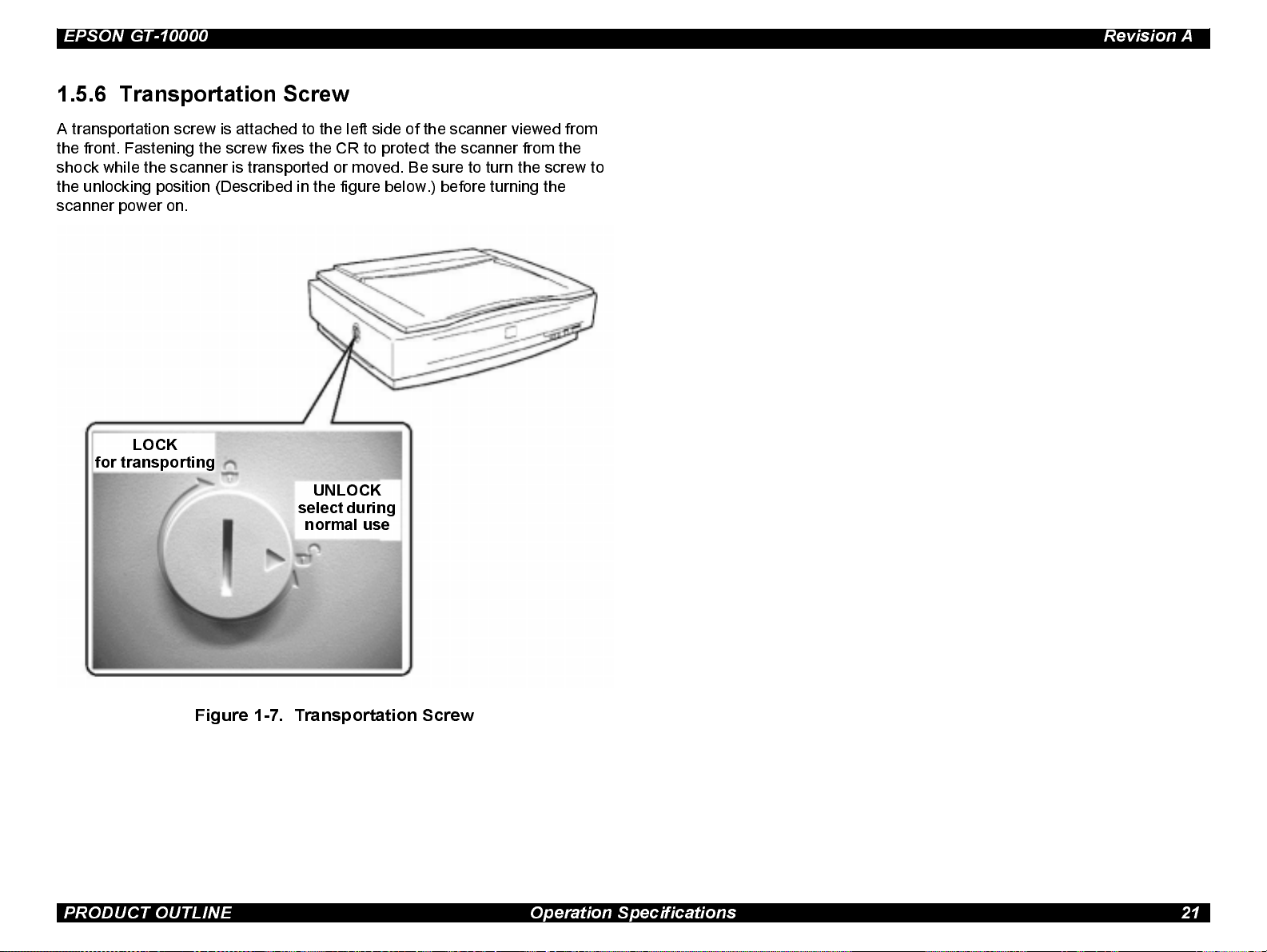
1.5.6 Transpo rtat io n Screw
A transporta ti on screw i s attached to th e left side of the scanner view ed from
the front. Fastening the screw fixes the CR to protect the scanner from the
shock while the scanner is transported or moved. Be sure to turn the screw to
the unlocking position (Described in the figure below.) before turning t he
scanner power on.
LOCK
for transportin g
UNLOCK
select during
normal use
Figure 1-7. Transportation Screw
PRODUCT OUTLINE Operation Specifications 21
Page 22
OPERATING PRINCIPLES
CHAPTER
2
Page 23
EPSON GT-10000 Revision A
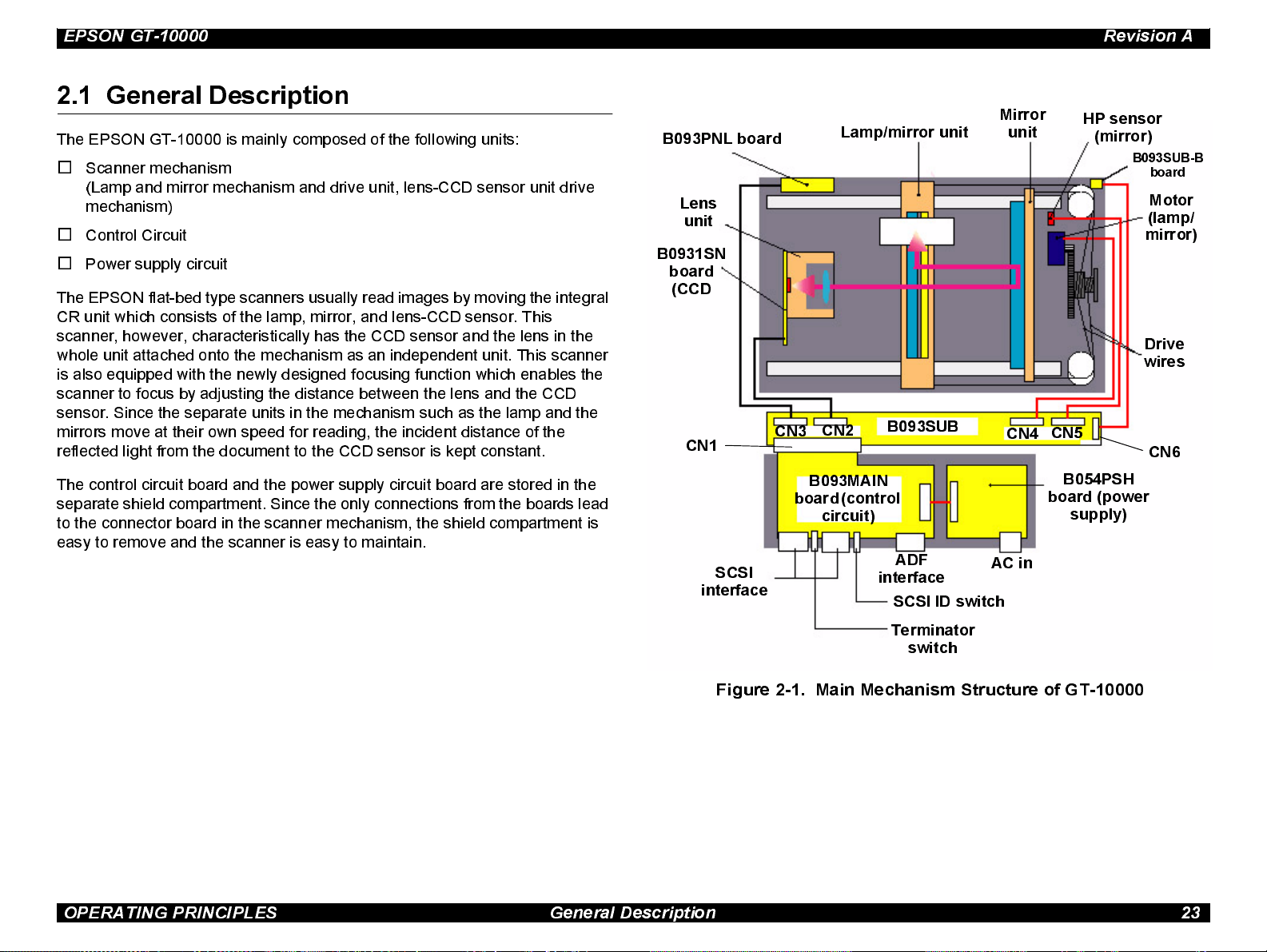
2.1 General Description
The EPSON GT-10000 i s mainly composed of the following uni ts :
o
Scanner mechanism
(Lamp and mirror mechanism and drive unit, lens-CCD sensor unit drive
mechanism)
o
Control Circuit
o
Power supply circuit
The EPSON flat-bed type scanners usually read images by moving the integral
CR unit which consists of the lamp, mirror, and lens-CCD sensor. This
scanner, however, characteristically has the CCD sensor and the lens in the
whole unit attached onto the mechanism as an independent unit. This scanner
is also equipped with the newly designed focusing function which enables the
scanner to focus by adjusting the distance between the lens and the CCD
sensor. Since the separate units in the mechanism such as the lamp and the
mirrors move at their own speed for reading, the incident distance of the
reflected light from the document to the CCD sensor is kept constant.
B093PNL board
Lens
unit
B0931SN
board
(CCD
CN1
CN3
Lamp/mirror unit
CN2
B093SUB
Mirror
unit
CN4
HP sensor
(mirror)
B093SUB-B
board
Motor
(lamp/
mirror)
Drive
wires
CN5
CN6
The control circuit board and the power supply circuit board are stored in the
separate shi eld compartment. Since the only connections from the boards lead
to the connector board in the scanner mechanism, the shield compartment is
easy to remove and the scanner is easy to maintain.
SCSI
interface
B093MAIN
board (control
circuit)
interface
Terminator
ADF
SCSI ID switch
switch
AC in
B054PSH
board (power
supply)
Figure 2-1. Main Mechanism Structure of GT-10000
OPERATI N G PRINC IPLE S Gene ral Des c ript ion 23
Page 24
EPSON GT-10000 Revision A
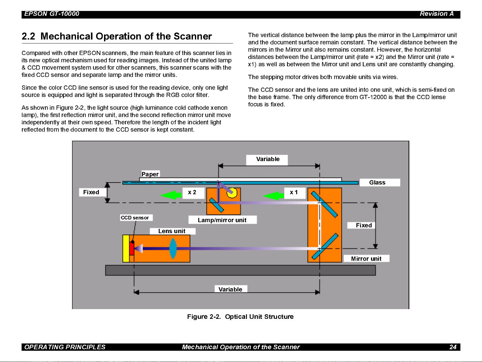
2.2 Mechanical Operation of the Scanner
Compared with other E PSON scanners, the main feature of this scanner lies in
its new optical mechanism used for reading images. Instead of the united lamp
& CCD movement system used for other scanners, this scanner scans with the
fix ed CCD sensor and separate lamp and the mirror units.
Since the color CCD line sensor is used for the reading device, only one light
source is equi pped and light is separated through the RGB color filter.
As shown in Figure 2-2, the light source (high luminance cold cat hode xenon
lamp), the first reflection mirror unit, and the second reflection mirror unit move
independently at their own speed. Therefore the length of the i ncident light
reflected from the document to the CCD sensor is kept constant.
Paper
Fixed
x 2
The ve rtical distance between the lamp plus the mirror in the Lamp/mirror unit
and the document surface remain constant. The vertical distance between the
mirrors i n the Mirror unit also remains constant . However, the horizontal
distances between the Lamp/mirror unit (rate = x2) and the Mirror unit (rate =
x1) as w ell as between the Mirror unit and Lens unit are constantly changing.
The stepp ing motor drives both movable units via wires.
The CCD sensor and the lens are united into one unit, which is semi-fixed on
the base frame. The only difference from GT-12000 is that the CCD lense
focus is fixed.
Variable
Glass
x 1
CCD sensor
Lens unit
Lamp/mirror unit
Fixed
Mirror unit
Variable
Figure 2-2. Optical Unit Structure
OPERATING PRINCIPLES Mechanical Ope ration of the Scanner 24
Page 25
EPSON GT-10000 Revision A
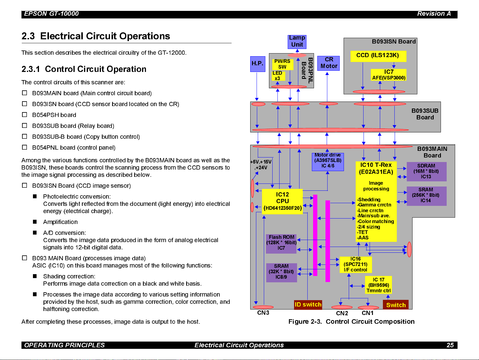
2.3 Electrical Circuit Operations
This section describes the electrical circuitry of the GT-12000.
2.3.1 Control Circuit Operation
The control circuits of this scanner are:
o
B093MAIN board (Main control circuit board)
o
B093ISN board (CCD sensor board located on the CR)
o
B054PSH board
o
B093SUB board (Relay board)
o
B093SUB-B board (Copy button control)
o
B054PNL board (control panel)
Among the various functions controlled by the B093MAIN board as well as the
B093ISN, thes e boards control the scanning process from the CCD sensors to
the image signal processing as described below.
o
B093ISN Board (CCD image sensor)
n
Photoelectric conversion:
Converts light reflected from the document (light energy) into electrical
energy (electrical charge).
n
Amplification
n
A/D conversi on:
Converts the image data produced in the form of analog electrical
signals into 12-bit digital data.
H.P.
+5V,+15V
,+24V
(
HD6412350F20
(128K * 16bit)
PW/RS
SW
LED
x3
IC12
CPU
Flash ROM
IC7
Lamp
Unit
B
o
a
r
d
)
B
CR
0
9
Motor
3
P
N
L
Motor drive
(A3957 SL B )
IC 4/5
B093ISN Board
CCD (ILS123K)
IC7
AFE(VSP3000)
IC10 T-Rex
(E02A31EA)
Image
processing
-Shedding
-Gamma crrctn
-Line crrctn
-Main/sub ave.
-Color matching
-2/4 sizing
-TET
-AAS
B093SUB
Board
B093MAIN
Board
SDRAM
(16M * 8bit)
IC13
SRAM
(256K * 8bit)
IC14
o
B093 MAIN Board (processes image data)
ASIC (IC10) on this board manages most of the following functions:
n
Shading correction:
Performs image data correction on a black and white basis.
n
Processes the image data according to various setting information
provided by the host, such as gamma correction, color correction, and
halftoning correction.
After completing these processes, image data is output to the host.
SRAM
(32K * 8bit)
IC8/9
ID switch
CN3
Figure 2-3. Control Circuit Composition
(SPC7211)
I/F control
CN2
IC16
IC 17
(BH9596)
Trmntr ctrl
Switch
CN1
OPERATING PRINCIPLES Electrical Circuit Operations 25
Page 26

EPSON GT-10000 Revision A
B093MAIN BOARD
Name Location Description
CPU
HD6412350F20
T-REX
E02A31EA
SPC7211 IC16
A3957SLB IC4/5 Motor drive control
BH9596 IC17 Terminator control
IC12
IC10
The CPU that controls this entire operation
of this board and operates at 20 MHz.
Voltage = 5.0V
The image processor that controls the
functions described below, operates at
48Mhz. Voltage = 3.3V
• CCD control
• Line correction processing
• Buffer memory
• Image processing
The SCSI interface processor operates at
40Mhz. Voltage = 5.0V
B093ISN BOARD
Name Location Description
Color CCD line sensor outline:
• Effective pixel = 7250 pixels x 3 colors
CCD sensor
ILX123K
IC9
• Light shield = 16 pixels x 3 colors
• Bi-D scanning rate = Max. 6 million
pixels/second
• Shutter function
±
10%
± 0.3V
± 10%.
B054PNL BOARD
This board has a power switch (push-lock), RESET switch and LED indicators
(OPERATE, READY, ERROR). (Same board used in GT-12000; compatible.)
2.3.2 Power Supply Circuit Operation
Since the power supply circuit board B054PSH for this scanner meets the
universal specification requirements, it can be used with rated voltage from
100V to 240V AC.
The electrical circuit for the AC input part is designed on the basis of
200V li ne. In case the input voltage is 200V line level, the ordinary full wave
rectifying system is used. With this system, the voltage is rectified by the diode
bridge DB1 and then smoothed by th e seri a l smoothing capacit ors C11 and
C32 to produce approximately 250 VDC.
On the other hand, if the input voltage is 100V line level, the double-voltage
rectifying system is used instead. With this system, the input AC current is
separated into the following 2 flows; the positive half cycles of the current flow
through the control IC (IC2) (from Pin 2 to Pin 3) via the diode bridge (DB1) and
the smoothing capacitor C11, and the negative half cycles of the current flow
through the smoothing capacitor (C32) and DB1 via IC2 (from Pin 3 to Pin 2).
Through these flows, the positive and negati ve AC current are separat ely
charged in the s moothing capacitors C11 and C32, respectively. The final
VDC (approximately 250 VDC) is equivalent to the output voltage produced by
the 200V line. At power-on, the control circuit (IC2) is activated by the full wave
rectifying system. Then, if the input voltage is the 100 VDC line level, the
system automatically switches to the double-voltage rectifying system after a
certain period set by the circuit.
ADC
VSP3000
IC2
A/D converter processing IC
Resolution = 12 bit
B093SUB BOARD
This relay board connects the B093MAIN board (which is located on a metal,
shielded tray) w ith the B093ISN and B054PNL boards.
OPERATING PRINCIPLES Electrical Circuit Operations 26
Page 27

EPSON GT-10000 Revision A
Except for the full wave rectifier circuit/voltage doubler rectifier circuit at the AC
input part , the normal RCC (Ringing Choke Converter) regulator circuit is used
for the rest part of the power supply circuit, and the different levels of VDC are
distributed to corresponding mechanisms, as shown in Table 2-1:
Table 2-1. DC Output Power
Output VDC Application
+5 V Logic power lines
+24 V
+15 V
• Motor drive power source
• Power source for the lamp (inverter)
+12 V production
(Drives the cooling fan for the metal, shielded tray that contains
the B093MAIN and B054PSH boards.)
Positive
Voltage
input
DB1
C11
Voltage
Negative
output
C32
IC2
AC input
100V = on
200V = off
Figure 2-4. Double-voltage Rectifier Circuit Operation
OPERATING PRINCIPLES Electrical Circuit Operations 27
Page 28

TROUBLESHOOTING
CHAPTER
3
Page 29

EPSON GT-10000 Revision A
3.1 Overview
This chapter describes troubleshooting techniques to help you solve any
scanner problems you may encounter. First see the next section to determine
what kind or error ha s occurred, and then see the appropriate explanation in
the following pages to determine the correct solution.
3.1.1 Errors and Causes of Errors
The self-diagnostic function equipped with this scanner automatically detects
the operating st atus of all major parts. The scanner communicates any
detected error and the cause of the error using a combination of the indicator
lights as described below.
COMMAND ERROR
Table 3-1.
LED Status Cause Operation/Condition
Ignores the wrong command
/parameter (no change made to
the current settings), and
returns NACK to wait for the
next command/ parameter.
Remedy
READY
ERROR
Received
undefined
command or illegal
parameter.
The error is cleared when a legal command or
parameter is received.
COMMUNICATION ERROR
Table 3-2.
LED Status Cause Operation/Condition
• Wrong communicati on
procedure or opera ti on
READY
ERROR
(flashing)
Remedy
detecte d.
• For SCSI I/F, if the error
occurred in any phase ex ce pt
“bus free ”, communica ti on
and operations stop for over
30 seconds.
• Turn the scanner off and back on or press the RESET button.
• For SCSI, se nd “RESET” signal.
The lamp goes off and the
scanner s tops oper at i ng.
FATAL ERROR
Table 3-3.
LED Status Cause Operation/Condition
• The lamp goes off and the
scanner s tops oper at i ng.
• Sets the sta tus bit to bit
“7”.
Remedy
READY
ERROR
(both
flashing)
Hardware error, such as
• The lam p does not li ght.
• Scanner turned on wit h the
CR unlocked.
• Other defects in the scanner.
• Turn the scanner off a nd back on or press the “ RESET”
switch.
• Send ini ti lia ze command *ESC @”.
• Send SCSI “bus device reset”
• For SCSI, se nd “RESET” signal.
TROUBLESHOOTING Overview 29
Page 30

EPSON GT-10000 Revision A
OPTION ERROR
Table 3-4.
LED Status Cause Operation/Condition
Option error, such as
REA DY
ERROR
Remedy Solve the error.
CHECK
PO INT
• The scanner cover is open.
• Paper out
• Other similar error
Sets the status bit to bit “7”.
An [Op tio n Error] can be detec ted on ly wh en the
optio n is pro pe rly ins talled .
3.1.2 Troubleshooting
This sect ion provides test points for each major unit and check points for each
abnormal phenomenon.
3.1.2.1 Test Points
Test poi nts for the motors and sensors are shown in the tables below .
MOTORS
Condition: Test the motor without any cables connected.
Table 3-5. Motor Check Points
Motor Test Point Signal Level
SENSORS
Condition: Test the sensors with the power on.
T able 3-6 . Sensor Check Points
Motor Te st Point Signal Level
• High when the mirror unit is
in the home position.
• Low when it is outside of its
home position.
HP sensor (Mirror)
CAUTION
Be careful no t to sho rt-c ircu it the signals while
<B093SUB board>
CN4: Pin 1 (Signal)
Pin 2 (GND)
checking them.
3.1.2.2 Troubleshooting Other Errors
See the table below for miscellaneous errors not covered in the previous
sections.
Table 3-7. In case of abnormal performance
Phenomenon Description Refer to Flowchart
The scanner doesn’t
operate at power on.
“Fatal Error” is indicated
and does not clear after the
scanner is turned off and
back on
“Communication Error” is
indicated
“OPERATE” LED d oes
not light.
CR does not move. Figure 3-1
Abnormal movement
of CR, such as
crashing into the
frame.
Lamp does not light. Figure 3-4
SCSI not set properly
or defective
Figure 3-1
Figure 3-3
Figure 3-5
Motor (for driving
the mirror)
<Cable connector>
Between Pins 1 and 3
Between Pins 2 and 4
15.0
Ω
The scanner does not scan
images properly.
Black lines, White
banding, and so on
Figure 3-6
TROUBLESHOOTING Overview 30
Page 31

EPSON GT-10000 Revision A
Flowchar t 3- 1. COperate light does not light up
Start
CN1 on B093SUB
not grounded
properly?
No
Has the fuse F1/F2
(B054SUB) blown?
No
Disconnect cables from
CN2/4/5/6 on B093SUB, and
then with power on test CN5
for the following voltages.
Bet ween Pin s:
1 and 4: +24V DC
7 and 4: +5V DC
9 and 10: +15V DC
Yes
Connect properly
Yes
Disconnect cables
from CN2/4/5/6 on
B093SUB, and replace
the fuse. Then turn on.
Did the fuse burn
out again?
Replace B054PSH
Yes
No
A
Check the resistance of
the mirror drive motor
coil: 15.0
A
Ω
Is it correct?
Yes
Replace
B093MAIN
No
Check the motor driver
IC on B093MAIN.
For Mirror motor
resistance between Pin
15/22 of IC4/5 and GND =
infinite
Yes
Is it correct?
No
Replace
B093MAIN
Are they correct?
No
Replace B054PSH
Replace the
motor
Yes
A
TROUBLESHOOTING Overview 31
Page 32

EPSON GT-10000 Revision A
Flowchar t 3- 2. CR (Mirror/ l amp) does not move
Star t
Transportation
screw set to locked
position?
No
Turn off the scanner and
manually move the carriage.
Does it move smoothly?
Yes
With power on, test CN5 on
B093MAIN.
Between Pin 1 and 4: +24V DC
Yes
No
Unlock the screw
Th e mech anism
is defective.
Replace it
A
Check the resistance
of the mirror motor
coil: 15.0
Ω
Is it correct?
Yes
Replace
B093MAIN
Replace the
motor
No
Check the motor driver
IC on B093MAIN.
For the mirror motor,
resistance between Pin
15/22 of IC4/5 and GND
= infinite
Yes
Is it correct?
No
Is it correct?
No
Replace
B054PSH
Yes
A
Replace
B093MAIN
TROUBLESHOOTING Overview 32
Page 33

EPSON GT-10000 Revision A
Flowchar t 3- 3 . CR moves abnormally (crashes into frame) Flowchart 3-4.
Start
Transportation
screw set to locked
position?
No
Test CN4 on B093MAIN for the HP
signal level.
Is the signal “High” when
CR is in home position?
Yes
Yes
Replace the lamp on the
Unlock the
screw
Does the lamp operate
Replace the inverter board on the
Replace
B093MAIN
Start
carriage.
normally?
No
carriage.
Lamp does not light
Yes
Old lamp was
defective.
No
Replace the HP
sensor (for mirror)
Does the lamp operate
normally?
No
Replace
B093MAI N
Yes
Old inver ter
was defective.
TROUBLESHOOTING Overview 33
Page 34

EPSON GT-10000 Revision A
Flowchart 3-5. SCSI I/F communication error occurs Flowchart 3-6. Scanned image is abnormal
Start
Make sure only the last SCSI
device in Daisy Chain is terminated
Make sure there are no SCSI ID
conflicts.
Are the settings correct?
Yes
Try another SCSI cable.
Does the scanner
operate properly?
No
Yes
Set them
correctly.
Old cable was
defective.
Replace.
Start
Stains or foreign
material on glass?
No
Stains or forei gn
material on mi rror ?
No
Replace B093M AI N an d perfo rm a
test scan.
Does the scanner
operate normally?
No
Yes
Yes
Yes
Clean the
glass
Clean the
mirro r
Old B093MAIN
was defective
No
Replace
B093MAIN
Replace the
mechans im
TROUBLESHOOTING Overview 34
Page 35

EPSON GT-10000 Revision A
3.1.3 Troubleshooting Circuit Board Errors
This s ection describes the check points for the electrical circuit boards.
3.1.3.1 Power Supply Board (B054PSH Board)
Tabl e 3- 8. B054PSH Board T r ouble sh ooti ng
Phenomenon Check Points
<Abnormal voltage>
+5VDC is not output.
<Abnormal voltage>
+24 VDC is not output.
<Abnormal voltage>
+15 VDC in not output.
3.1.3.2 Control Circuit Board (B093MAIN Board)
Table 3-9. B093MAIN Board Troubleshooting
Phenomenon Check Points
<No operation at all>
Reset IC is defective.
Test the signal waveform output between Pins 8
and 11 (chopping waveform) for IC51 (TL494)
Test the drain waveform at the Switching FET/Q1
Test the signal waveform output from Pin 1 for
IC52 (78M15)
Check the reset IC (IC11) for the signal
waveforms output from the following
pins:
Pin 7 (for +5V input)
Pin 5 (for PWRS output)
Table 3-9. B093MAIN Board Troubleshooting (continued)
Phenomenon Check Points
<”Fatal Error”>
Carriage does not stop at the home
position.
<”Fatal Error”>
Lamp does not light.
<”Fatal Error”>
White standard level is not read
properly.
<”Communication Error”>
Bi-directional I/F and SCSI I/F
<Image is read abnormally>
Check if the signal waveform input to Pin
110 of the CPU (IC12) changes in
accordance with the CR position.
Check the output from Pin 95 of ASIC
(IC12)
Check the signal output waveform for
ASIC (IC12) Pin 202:
Main cause: ASIC (IC16) is defective.
(Replace IC16 or B093MAIN board.)
Main cause: ASIC (IC10) is defective.
(Replace IC10 or B093MAIN board.)
Check the CPU (IC12) for the ROM
<No operation at all>
EPROM access error
<No operation at all>
CPU is defective.
<”Fatal Error”>
Motor (for mirror) drive circuit is
defective.
access signal waveforms output from the
following pins:
Pin 2 (for CS0 signal)
Pin 91 (for RD signal)
Check the clock signal waveform input to
the following pin:
Pin 85 (for XTAL input)
Check the Driver IC (IC 4/5) Phase drive
signal waveform output from Pin 15/22
TROUBLESHOOTING Overview 35
Page 36

DISASSEMBLY & ASSEMBLY
CHAPTER
4
Page 37

GT-10000 Revision A
4.1 Overview
This chapter describes how to disassemble this scanner. Unless ot herwise
specifi ed, assembly can be accomplished by following disassembly procedures
in reverse order.
n
W ARNING
CAUTION
Be sure to disconnect the power cable from the AC power
socket prior to servicing.
n
Since this scanner weighs h eavy (approximately 20 kg), it
must be carried b y two people.
n
Never disassemble any scanner parts unless specified to
do so, because th is scanner mechanism needs precise
assembly and adj ustment to maintain accurate control
system at its satisfactory level.
n
Secure yourself enough roo m for servicing, considering
the size o f the scanner.
n
Since this scanner weighs as heavy as approximately 20
kg, be sure to perform servicing on a heavy-duty, level
table.
n
Make sure that the “CR fixing knob” is set to the locking
position to fix the CR by the rear before packing the
scanner for transportati on.
4.1.1 Tools
Tools used for servicing are as listed in the table below:
Table 4-1. Tool List
Description Availability SE Parts Code Reference
(+) Screw Driver (No. 2)
(+) Screw Driver (No. 1)
Box Driver (Diagonal: 6mm)
Box Driver (Diagonal: 5mm)
Tweezers
Leveling Tools (3 stages and 1
adjuster as 1 set)
Mechanism Lift Handle
Light Correcting Panel
White Standa rd Char t
¤
¤
¤
¤
¤
¢
¢
¢
¢
- Versatile
- ditto
- ditto
- ditto
- ditto
1039140
1040176 ditto
1050003
1050004
Same as
GT-12000
Exclusively
desi gned for GT-
10000.
Exclusively
designed for GT-
10000.
(Must be attached
to the Light
Correcting Panel
before use.)
¤
Commercially available.
¢
Not commercially available.
DISASSEMBLY & ASSEMBLY Overview 37
Page 38

GT-10000 Revision A
4.1.2 Screws
Screws used in this scanner are listed in the table below. However, the list
does not include the screws which are used for servicing not specified in this
manual. Be sure to use the correct types and numbers of screws for each part
when assembling the scanner.
Table 4-2. Screw List
No.
1 CPFS M3x8 Black
2 CB M3x6 Gold
3 CP M2.5x8 Silver
Screw Type /
Specification
Appearance Color
Table 4-2. Screw List (continued)
No.
6 CPS M4x12 Silver
7 CB M4x10 Gold
8 CPS M4x18 Gold
Screw Type /
Specification
Appearance Color
9 CR; B Damper Shaft Gold
4
5
Screw Lock Screw
(Diagonal: 5 mm)
Brass Spacer (Hexagon)
(Diagonal: 6mm)
Silver
10 CB M3x3 Gold
Silver
DISASSEMBLY & ASSEMBLY Overview 38
Page 39

GT-10000 Revision A
Table 4-2. Screw List (continued)
No.
11 CB M3x12 Black
12 CB M4x6 Gold
13 CPFS M3x8 Gold
Screw Type /
Specification
Appearance Color
DISASSEMBLY & ASSEMBLY Overview 39
Page 40

GT-10000 Revision A
4.2 Disassembly Procedu res
Document Cover
This section describes disas se mbling and removing procedures for each major
unit of the scanner.
Removal
(Section 4.2.1)
See the flowchart in F i gure 4-1. The jobs in the yellow box i nvolve use of the
adjusting tools exclusi vely designed for this scanner. Therefore, make sure that
you read the i ns tructions in each secti o n carefully t o figure out the procedures
before servi ci ng.
Electrical Circuit
Removal
(Section 4.2.2)
Scanner Body
Disassembly
(Section 4.2.3)
Scanner Mechanism
Disassembly
(Section 4.2.4)
Main Boards Removal
(Section 4.2.2.1)
Upper Housing Removal
(Section 4.2.3.1)
Mechanism Removal
(Section 4.2.3.2)
Panel Board Assembly Removal
(Section 4.2.4.1)
Sub Board Assembly Removal
(Section 4.2.4.2)
HP Sensor (CR) Removal
(Section 4.2.4.3)
Motor (CR) Assembly Removal
(Section 4.2.4.4)
Glass Frame Assembly Removal
(Section 4.2.4.5)
Lamp/Inverter Board Assembly
Removal (Section 4.2.4.6)
Option Frame Assembly Removal
(Section 4.2.4.7)
Figure 4-1. Disassembly Procedure for GT-10000
DISASSEMBLY & ASSEMBLY Disassembly Procedures 40
Page 41

GT-10000 Revision A
4.2. 1 Docum ent Cover Unit Removal
4.2.2 Electrical Circuit Removal
The major electrical circuit boards (B093MAIN and B054PSH) of this scanner
are all stored in one independent shield compartment. Therefore, they can be
removed in one unit (board unit) from the scanner with ease.
1. Disconnect the AC power cable from the scanner.
2. Remove 3 screws (No.1) securing the shield compartment which contains
the electrical circuit boards at the back of the scanner. Then take out the
compartment from the scanner.
Figure 4- 3. Shiel d Compar t me nt Remov a l
CHECK
PO INT
For easy removal, pull the translucent card spacers located
at both sides of the shield compartment.
Figure 4-2. Document Cover Unit Removal
DISASSEMBLY & ASSEMBLY Disassembly Procedures 41
Page 42

GT-10000 Revision A
4.2.2.1 Main Boards Removal
Main boards stored in the shield compartment should be removed in the
following procedure:
1. Remove the shield compartment. (See 4.2.2.)
2. Remove 18 screws (No.2) securing the top shield and the top shield cover,
and remove both units together.
Figure 4- 4. Removal of Top Shiel d and Shield Cove r
3. Main Boar d Assembly Rem o val
Disconnect the connector cables from connectors CN5 and CN7 on the main
board assembly.
4. Remove the following s crews securing the main board assembly, and a
brass spacer securi ng the top shield, and remove the main board:
n
6 screws: No. 2, securing the board along the edges.
n
6 screws: No. 3 = 4 screws securing the SCS II I/F connector; No. 4 = 2
screws securing the ADF OPTION connector.
DISASSEMBLY & ASSEMBLY Disassembly Procedures 42
Page 43

GT-10000 Revision A
5. Power Supply Board Assembly Removal
Connector CN7
Connector CN5
Fixing Screws (No.2)
Brass Spacer (Hexagon)
n
Remove the connector cables from connector CN1 on the power
supply board ass embly and connector CN5 on the main board
assembly.
6. Remove 6 screws (No.2) securing the power supply board assembly and
remove the power s upply board.
Power Supply Connector CN1
Figure 4-5. Main Board Assembly Removal (a)
Power Sup ply Board Fixing
Screws (No.2)
Main Board
Connector CN5
Figure 4-7. Power Supply Board Assembly Removal
SCSI I/F Fixing Screws
ADF Option I/F
Fixing Screws
Figure 4-6. Main Board Assembly Removal (b)
DISASSEMBLY & ASSEMBLY Disassembly Procedures 43
Page 44

GT-10000 Revision A
4.2.3 Scanner Body Disassembly
This s ection describes procedures for disassembling the major units of the
scanner.
4.2.3.1 Upper Housing Removal
CAUTIO N
1. Remove the document cover (See Figure 4.2).
2. Usi ng tw e ezers, remove t he CR fixi ng knob at tached to the left si de of the
scanner.
3. Remove 4 screw s (2 for each of No.6 and No.7) securing the upper
housing to the chass i s on the s canner. Note that the 2 front screw s are
covered w i th the screw caps. Pinch them out wit h tw eezers pri or to
removing the screws.
4. Lift up th e upper hous ing to remov e i t.
CHECK
PO INT
When removing the CR fixing knob or screw caps, take
cautions not to damage the upper housing.
When reinstalling the upper housing, make sure that the
optical plate is installed on the specified position.
Screw
6
(No.6)
CR Fixing Knob
Screw
Cap
Screw
(No.7)
Screw Cap
Figure 4-8. Upper Housing Removal
Remove the cap by lifting it up
while pushing it toward the other
side of the cutout.
Cross-section
Screw Cap
Be careful not to damage
the upper housing.
Figure 4-9. Screw Caps Removal
DISASSEMBLY & ASSEMBLY Disassembly Procedures 44
Page 45

GT-10000 Revision A
Optical Plate
Figure 4-10. Optical Plate Installation
Inner Side of the
Upper Housing
CHECK
PO INT
Note the following when installing the scanner mechanism:
n
Remove key tops for the power switch and reset
switches from the lo wer housing.
n
Install the sca nner mechanism to the lower housing.
n
Reinstall the key tops.
Place the removed mechanism on flat stable surface.
4.2.3.2 Scanner Mechanism Removal
The scanner mechanism can be removed from the lower housing in the
following procedure:
1. Remove the upper housing (See 4.2.3.1).
2. Remove 4 screws (No.8) securing the scanner mechanism to the lower
housing. Then remove the mechanism from the lower housing.
DISASSEMBLY & ASSEMBLY Disassembly Procedures 45
Page 46

GT-10000 Revision A
4.2.4 Scanner Mechanism Disassembly
The rest of the chapter describes procedures for removing the major parts/
units in the scanner mechanism.
CAUTIO N
Note that producing this scanner requires precise assembly
and adjustment to ensure ac curate control system.
Therefore, n ever disassemble any scanner parts unless
specified to do so.
4.2.4.1 Panel Board Assembly Removal
1. Remove the scanner mechanism (See 4.2.3.2).
2. Turn the mechanism over and place it on a flat surface.
3. Disconnect the white cable from CN1 and the black cable from CN2 of the
panel board as sembly.
4. Remove 2 screws (No.2) securing the panel board assembly, and remove
the assembly.
CHECK
PO INT
Unit arrangement at the bottom of the mechanism is as
shown on the following page.
Figure 4-11. Scanner Mechanism Removal
DISASSEMBLY & ASSEMBLY Disassembly Procedures 46
Page 47

GT-10000 Revision A
4.2.4.2 Sub Board Assembly Removal
CR Motor Assembly
Figure 4- 12 . Unit Arrangement
CR HP Sensor
Sub Board Assembly
CN1CN2
Panel Board Assembly
1. Remove the scanner mechanism (See 4.2.3.2).
2. Turn the mechanism over and place it on a flat surface.
3. Disconnect all connector cables from the sub board assembly (B093SUB).
4. Remove 4 screws (No.3) securing the board to the bracket, and remove
the board.
CHECK
PO INT
CN6 CN2
When placing the scanner up side down, lay a clean soft
cloth under the scanner to protect the glass surface.
CN5
CN4
CN3
Panel Board Assy
Screws (No.2)
Screws (No.2)
Figure 4- 14 . Sub Board Assembl y Remov al
Figure 4-13. Panel Board Assembly Removal
DISASSEMBLY & ASSEMBLY Disassembly Procedures 47
Page 48

GT-10000 Revision A
4.2.4.3 HP Sensor (CR) Removal
This section describes procedure for removing the HP sensor which detects
reference position of the carriage mirror assembly.
1. Remove the scanner mechanism (See 4.2.3.2).
2. Unlock the carriage fixing screws, and move the carriage mirror assembly
away from the HP.
3. Turn the mechanism over and place it on a flat surface.
4. Release the hook fixing the HP sensor at the bottom of the mechanism and
remove the HP sensor unit. Then disconnect the connector cable from the
removed HP sensor.
CR Motor Assembly
CR HP Sensor
Panel Board Assembly
4.2.4.4 CR Motor Assembly Removal
This section describes procedure for removing the motor unit which drives the
carriage mechanism (mirror/lamp).
1. Remove the scanner mechanism (See 4.2.3.2).
2. Turn the mechanism over and place it on a flat surface.
3. Unhook the torsion spring from the tension lever assembly, then remove 1
screw (No.13) and the bush to remove the tension lever assembly.
4. Disconnect the cable for the motor from the relay connector and remove 4
CR; B damper shafts (No.9), and then remove the motor.
CHECK
PO INT
When assembling, hook the spring to the tension lever
assembly first, and fasten the screws.
Sub Board Assembly
Figure 4-15. HP Sensor (CR) Removal
DISASSEMBLY & ASSEMBLY Disassembly Procedures 48
Page 49

GT-10000 Revision A
4.2.4.5 Glass Frame Assembly Removal
CR; B Damper Shafts
Top of the Scanner
Screw (No.13)
Figure 4-16. CR Motor Assembly Remova l
Since the glass frame assembly (document glass) is one of the reinforcing
parts of the mechanism, the whole scanner mechanism may be deformed if it is
removed. Be sure to follow the instruction provided in this section during any
servicin g whic h involves rem oving the gla ss frame assembly.
.
n
CAUTIO N
When removing the document glass, m ake sure to set the
scanner on the ad justing tools exclusively designed for
this scanner.
n
Be sure to fit all the rubber feet of the scanner in the top
indents of the stages and the adjuster (Any of the feed
should not be placed over the top surface of the tools).
n
Set the scanner on a stable and level table.
n
Make sure that the scanner mechanism is installed in the
lower housing when removing the glass frame assembly.
Turning Table
(with 4 divisions)
Base
(with 1 groove)
Stage
(3 pieces)
Adjuster
Figure 4- 17 . Adjusting T ools
DISASSEMBLY & ASSEMBLY Disassembly Procedures 49
Page 50

GT-10000 Revision A
n
Turn the t able manually [2 quarters], which can be measured by 4
divis ions on the table and the groove on the base, to push the table up
from the posi tion where the table was moved up to by the spin.
n
After adjusting, make sure that each corner of the scanner is securely
in contact with the corresponding tool.
3. Remove 9 screws (No.10) and remove the glass frame assembly. The
screws to be removed and their locations are shown on the following page.
Stage
(Set in the front left,
rear right and rear
left corners.)
Adjuster
(Set in the front
right corner.)
Turn the turning table to
move the table up and
down to adjust height.
Figure 4-18. Tool Position and Adjusting Method
1. Remove the upper housing (See 4.2.3.1).
2. Referring to Figure 4-18, set the scanner on the adjusting tools (leveling
tools) and level the scanner according to the following procedure:
n
Set the scanner on 3 stages, placing each of the specified rubber feet
on the corresponding stage.
n
Set the adjuster under the rubber foot in the front right corner of the
scanner bottom, aligning the center of the adjuster with the foot. Make
sure that you can see the groove on the base of the adjuster when it is
set.
CAUTIO N
When reinstalling the glass frame assembly, refer to
Section 4.2.3.5 .1 to confirm the correct installation position.
Misplacing of the glass frame assembly will cause the CR to
scan the document from a wrong position.
n
Hold the bas e of the adjuster with a hand and spin the table until i t
reaches the bottom of the scanner by its own force.
DISASSEMBLY & ASSEMBLY Disassembly Procedures 50
Page 51

GT-10000 Revision A
n
Push the whole glass frame assembly from the front against the frange
Screws (No.10)
Screws
(No.10)
Screws
(No.10)
shaft stoppers until the glass edge is in contact with the bus hes.
n
Keeping the glas s frame assembly in contact with the stoppers, move
the assembly toward left and push it against the positioning bump
located on t he top surface of the left side frame.
n
When the glass frame assembly is in the correct position, fix it with 9
screws.
Screws
(No.10)
Front of the Scanner
Figure 4-19. Glass Frame Assembly Removal
4.2.4.5.1 Glass Frame Assembly Installation
After the glass frame assembly has been removed for any purpose, it must be
reinstalled in the following procedure.
1. Place the glass frame assembly on the specified position in the scanner
mechanism.
2. While referring to Figure 4-20, determine the installation position according
to the following procedure:
CHECK
PO INT
Positioning Bump
When installing the glass frame assembly, ensure that
glass fixing plates (one for each of the front and rear) are
properly positioned (See Figure 4-19).
Frange Shaft Stoppers
Figure 4-20. Determining the Glass Frame Assembly Position
n
Install the frange shaft stoppers at the 2 bumps located in the rear
frame.
DISASSEMBLY & ASSEMBLY Disassembly Procedures 51
Page 52

GT-10000 Revision A
4.2.4.6 Lamp Assembly and Inverter Board Assembly
Removal
This section describes how to remove the lamp assembly and the inverter
board assembly from the carriage.
1. Remove the glass frame assembly (See 4.2.3.5).
2. Move the CR to the position indicated in Figure 4-22 (the position where
the front and rear frames are indented).
3. Remove 2 screws (No.2) securing the carriage mirror cover, and slide the
cover toward the rear side of the scanner to release the engagement with
the hook on the carriage. Then lift up the cover and remove it.
Screw (No.2)
4. Disconnect the connector cable for the lamp from the connector (CN2,
white) on the inverter board assembly. Then remove the lamp from the
carriage.
5. Disconnect the cable (black) from the connector (CN1) on the inverter
board ass embly. Then remove the bracket (silver) fixing t he ferrite core.
6. Remove 2 screws (No.2 ) securing the inverter board assembly.
7. Slide the inv erter board assembly toward the front side of the scanner to
release the engagement with the hook on the carriage. Then remove the
inverter board.
Figure 4-21. Carriage Mirror Cover Removal
DISASSEMBLY & ASSEMBLY Disassembly Procedures 52
Page 53

GT-10000 Revision A
Lift up to remove.
p
m
a
L
CN2
Cut Part of the Board
Screws (No.2)
CHECK
PO INT
When assembling , make sure that the cover is securely
engaged with the hook on the carriage.
Hook
Rear
Cover
Carriage Base
Front
CN1
Figure 4-22. Lamp Assembly and Inverter Board Assembly
Removal
DISASSEMBLY & ASSEMBLY Disassembly Procedures 53
Page 54

GT-10000 Revision A
4.2.4.7 Option Frame Assembly Removal
This s ection describes how to remove the option frame assembly attached to
the back of this scanner.
1. Remove the upper housing (See 4.2.3.1).)
2. Remove 8 screws securing the option frame assembly to the back of the
scanner and remove it. The types and locations of the screws to be
removed are as follows:
n
No.11: Locat ed in the upper right corner of the option frame assembly
(when view ed from the back of the scanner).
n
No.12: Rest of the positions are indicated in Figure 4-23 Option Frame
Assembly Removal below.
Screw (No.11)
Screws (No.12)
Figure 4-23. Option Frame Assembly Removal
DISASSEMBLY & ASSEMBLY Disassembly Procedures 54
Page 55

ADJUSTMENTS
CHAPTER
5
Page 56

EPSON GT-10000 Revision A
Confirm the installation folder, and click “OK”. The program will be
5.1 Upd ating Firmware
To update the firmware, the following are necessary:
o
Update Program (K90E02V)
o
SCSI Cable
o
automatically installed (data file of the firmware will be placed in the same
installation folder), and the following program group will be created on the
PC.
5.1.1 Preparations Before Updating
1. Select non-synchronized connection for SCSI on the PC (See manual for
each SCSI board). However, since the selection of non-synchronized or
synchronized setting cannot be made for the SCSI board which is not
equipped with BIOS, it is necessary to check each SCSI board beforehand.
2. Install the Update Program for the firmware according to the procedure
shown below.
o
Double-click the program “K90E02V.exe” located in the “Firmware” folder,
and the following screen will appear.
Figure 5-2.
Figure 5-1. Installation of Firmware Program
ADJUSTMENTS Updating Firmware 56
Page 57

EPSON GT-10000 Revision A
5.1.2 Updating Firmware
1. Connect the scanner to the PC v ia SCSI.
2. Turn on the PC and Windows.
3. Bring up EFlash, and the EFlash start screen shown in Figure 5-3 will
appear.
4. Click “About” button to display information on the program and the required
environment as shown in Figure 5-4.
Figure 5-4. Firmware Update Requirements and Environment
5. Double-click anywhere in the above screen other than “OK” button to
Figure 5-3. Firmware Update Start Screen
display “Option” screen (shown in Figure 5-5 on the following page), and
select light correction value setting for the firmware update at “Light
Correction Value”. If the light correction is necessary after updating the
firmware, select “[Production] Perform Light Correction after EFlash”. If
firmware updat e only is desired, select “[User Update] Save and Restore
the current value”. To specify the light v alue, select “[Special] Force t o
wri te the specified value” and enter the light value.
ADJUSTMENTS Updating Firmware 57
Page 58

EPSON GT-10000 Revision A
10. 1). In Figure 5-6, confirm the version of writing firmware. Name of the
scanner and the current version of ROM are shown at “Target Scanner”,
and the latest version of firmware data is shown right below.
Figure 5-6.
2). Click “Next” button for Flash Reservation.
Figure 5-5. Option Window
6. Click “OK” button in Fi gure 5-5 to go back to Figure 5-4.
7. Click “OK” button in Fi gure 5-4 to go back to Figure 5-3.
8. Make sure that the scanner is ready (green lamp is on).
9. In Figure 5-3, click “Next” button and upload the firmware according to the
following procedure:
ADJUSTMENTS Updating Firmware 58
Page 59

EPSON GT-10000 Revision A
3). When the Flash Reservation is complete, “REBOOT SCANNER!”
message box will appear (Figure 5-5).
Figure 5-7.
4). Reboot the scanner. You cannot proceed to the next step without
rebooting the scanner. Make sure that “Ready” lamp is on.
5). Click “O K” to start writing the firmware. Writi ng status is indicated by
the progress bar as shown in Figure 5-8 below. When writi ng process is
complete, “REBOOT SCANNER!” message will appear on the screen
again.
Figure 5-8.
ADJUSTMENTS Updating Firmware 59
Page 60

EPSON GT-10000 Revision A
6). Reboot the scanne r and click “OK”. The reboot message box will be
closed and Figure 5-9 will appear on the screen.
Figure 5-10.
Figure 5-9.
7). Make sure that the scanner is ready, and click “Next”. Figure 5-10 will
appear and the scanner version information “Before EFlash” and “After
EFlash” wi ll be displayed. Compare the version before and after EF lash to
confirm that the firmware has been properly written.
8). Click “Next” to go b a ck to the EFlash Start Screen.
9). Click “Cancel” to complete the firmware updating procedure.
ADJUSTMENTS Updating Firmware 60
Page 61

EPSON GT-10000 Revision A
5.2 Light Correction
GT-10000 requires the light correction after the disassembly and assembly
procedures described in Chapter 4. Since the Firmware Update Program has
“Light Correction Value” setting as shown in 5.1 Updating Firmware, it is
recommended that the light correction be conducted together with the firmware
update.
5.2.1 Necessary Tools
No. Tool Name Function Remark
Light Correcting
1
Plate
White Standard
2
Chart
Decides position of the
White Standard Chart
and works as a weight.
Functions as white
standard for the light
correction.
Two pieces must
be used as one
set.
Must be attached
to the Light
Correcting Plate
before use.
SEC Parts
Code
1050003
1050004
5.2.2 Light Correction Procedure
This section describes the procedure for conducting the light correction.
1. Turn off the scanner.
2. Select the SCSI ID 9 with the rotary switch as shown in Figure 5-8 (factory
default is 2). ID 9 is not indicat ed on the switch panel; however, when
turning the switch counterclockwise from 0, the next ID is 9.
Figure 5- 11 . SCSI ID for Light Correction
ADJUSTMENTS Light Correction 61
Page 62

EPSON GT-10000 Revision A
3. Remove the Document Unit Cover, and place the light correction tools
(Light Correcting Plates att ached w i th the Whi te S tan dard Chart) on the
glass as shown i n Figure 5-12.
CAUTIO N
4. While pressing the push button, turn on the scanner. Keep pressing the
push button until the lamp turns on.
5. The scanner will automatically correct the light value.
6. Turn off the scanner, and set t he SCSI ID rotary switch back to No. 2. The
light correct ion process is now complete.
n
To ensure the accurate light correction value, the White
Standard Chart which has flaws or smudges on its surface
must be replaced.
n
Replacement procedure for the White Standard Chart is as
follows:
- Peel off the double-face ta pe attached to the White Standard
Chart.
- Attach the White Standard Chart to the Light Correcting
Plates al ong the two lines engraved on the plate surface.
CAUTIO N
If the corrected light value does not meet the standard
values, error lamp on the front control panel flashes to
indicate an error. In such a case, it is necessary to conduct
the light correctio n again.
Figure 5-12. Light Correcting Plates Setting
CHECK
PO INT
White Standard Chart must be tightly attached to the glass
surface.
n
Use two Ligh t Correcting Plates as one set.
CHECK
PO INT
The corrected light value cannot be confirmed until the next
time the light correction is conducted (See Figure 5-13).
n
ADJUSTMENTS Light Correction 62
Page 63

EPSON GT-1000
0
A
S
n
3
Figure 5-13. Light Value of t he Scanner
Revision
ADJUSTMENT
Light Correctio
6
Page 64

MAINTENANCE
CHAPTER
6
Page 65

EPSON GT-10000 Revision A
Maintenance procedures for GT-10000 are the same as those of GT-12000.
MAINTENANCE 65
Page 66

APPENDIX
CHAPTER
7
Page 67

EPSON GT-10000 Revision A
7.1 Connector Pin A ss ig nm ent
7.1.1 Connector Pin Assignment
Scanner Mechanism
B054PNL
Board
CN3
B0931SN
Board
CN2
CN1
CN4
Motor
(Mirror)
CN4
B093SUB Board
HP Sensor
(Mirror)
CN5
B054PSH Board
Scan
Navigation
Button
6
N
C
7.1.2 Connector Summary
Connectors used on the electrical circuit boards are summarized in the table
below.
Table 7-1. Connector Summary
Board
B093MAIN
B054PSH
CN
No.
CN1 For connection with SCSI I/F 7.1.2.1 Table 7-4
CN2 For connection with SCSI I/F 7.1.2.1 Table 7-4
CN3 For connection with ADF/TPU Option 7.1.2.1 Table 7-6
CN4 For connection with B093SUB Board 7.1.2.1 Table 7-2
CN5 Power supply line from B054PSH Board 7.1.2.1 Table 7-3
CN1 For connection with AC inlet –
CN2 Power supply line for B093MAIN Board
CN1 For connection to B093MAIN Board 7.1.2.1 Table 7-2
CN2 For connection to B093ISN Board –
CN3 For connection to B054PNL Board
Function Ref.
GT-12000 Service
Manual 7-3
GT-12000 Service
Manual 7-4
GT-12000 Service
Manual 7-5
GT-12000 Service
Manual 7-5
–
CN2
SCSI
I/F
B093MAIN Board
CN1SW
SCSI
I/F
SWD1
CN3
ADF/TPU
I/F
B093SUB
5
N
C
2
N
C
CN1
CN4 For connection to the motor
CN5 For connection to HP sensor (mirror)
CN6
For connection to Scan Navigation Button
Board
AC Input
APPENDIX Connector Pin Assignment 67
Page 68

EPSON GT-10000 Revision A
7.1.2.1 Main Board Circuit Signals
B093MAIN – RELAY CONNECTOR (CN4)
Table 7-2.
PIN No. Signal Name Function
1 GND GND
2 GND GND
3 GND GND
4 ADCLK AD clock
5 CLP Not used.
6 GND GND
7 STB Shutte r (bl ue ) for CCD
8 STR Shutter (red) for CCD
9 RS Reset signal for CCD
10 GND GND
11 CLKA Cl ock si gnal for CCD
12 GND GND
13 AD1 Image data (1) af te r AD conversion
14 AD3 Image data (3) af te r AD conversion
15 AD5 Image data (5) af te r AD conversion
16 AD7 Image data (7) af te r AD conversion
17 AD9 Image data (9) af te r AD conversion
18 AD11 I ma ge data (11) aft e r AD conve rs i on
19 SLOAD Serial light signal for ADC
20 SCK1 Serial clock signal for ADC
21 OPSW Powe r swi tch (s econdar y side )
Table 7-2.
PIN No. Signal Name Function
22 LEDP LED (POWER)
23 LEDR LED (ERROR)
24 GND GND
25 GND GND
26 +24V Power supply (+24V)
27 +24V Power supply (+24V)
28 HMMP Home sensor power supply
29 MMB Motor (Phase B)
30 MMBX Motor (Phase /B)
31 +12V Power supply (+12V)
32 +12V Power supply (+12V)
33 LCMP Clamp signal for ADC, Start signal
34 GND GND
35 CDS2 Data sampling signal for ADC
36 CDS1 Reference sampling signal for ADC
37 STG Shutter (green) for CCD
38 GND GND
39 CLKC LH signal for CCD
40 CLKB Not used.
41 SHFT Shift signal for CCD
42 AD0 Image data (0) after AD conversion
43 AD2 Image data (2) after AD conversion
44 AD4 Image data (4) after AD conversion
45 AD6 Image data (6) after AD conversion
46 AD8 Image data (8) after AD conversion
APPENDIX Connector Pin Assignment 68
Page 69

EPSON GT-10000 Revision A
Table 7-2.
PIN No. Signal Name Function
47 AD10 Image data (10) after AD conversion
48 GND GND
49 SDAT1 Serial data signal for ADC
50 PUSHB Push button si gnal
51 RSSW Reset switch
52 LEDR LED (READY)
53 +5V Power supply (+5V)
54 GND GND
55 LMP Lamp signal
56 +24V Powe r supply (+24V)
57 HMM Home se ns or signal
58 MMA Motor (Phase A)
59 MMAX Motor (Phase /A)
60 GND GND
Table 7-3.
PIN No. Signal Name Function
7 +5V Power supply (for logic line)
8 +5V Power supply (for logic line)
9 +15V Power supply (for generating +12V)
10 GND GND
11 TEMP Output from the thermistor
12 OPSW Power switch (secondary side) control signal
B093MAIN - POWER SUPPLY CONNECTOR (CN5)
Table 7-3.
PIN No. Signal Name Function
1 +24V Powe r s upply (for motor dri ve, la m p)
2 +24V Power supply (for motor drive, lamp)
3 +24V Power supply (for motor drive, lamp)
4 GND GND
5 GND GND
6 GND GND
APPENDIX Connector Pin Assignment 69
Page 70

EPSON GT-10000 Revision A
B093MAIN – SCSI I/F CONNECTOR (CN1, CN2)
Table 7-4.
PIN No. Signal Name
1GND
2 GND
3GND
4 GND
5GND
6 GND
7GND
8 GND
9GND
10 GND
11 GND
12 GND
13 -------------(NC)
Table 7-4. (continued)
PIN No. Signal Name
24 GND
25 GND
26 SD0
27 SD1
28 SD2
29 SD3
30 SD4
31 SD5
32 SD6
33 SD7
34 SDP
35 GND
36 GND
37 GND
38 TERM PWR
14 GND
15 GND
16 GND
17 GND
18 GND
19 GND
20 GND
21 GND
22 GND
23 GND
39 GND
40 GND
41 /ATN
42 GND
43 /BSY
44 /ACK
45 /RST
46 /MSG
47 /SEL
APPENDIX Connector Pin Assignment 70
Page 71

EPSON GT-10000 Revision A
Table 7-4. (continued)
PIN No. Signal Name
48 /CD
49 /REG
50 /IO
B093MAIN – FAN CONNECTOR (CN2)
Table 7-5.
PIN No. Signal Name
1+12
2 GND
B093MAIN - OPTION CONNECTOR (CN3)
Table 7-6.
PIN No. Signal Name Function
1 IN1 Not used (TPU[HOME]/Select)
2 IN1 Not used (TPU[COVER]/Select)
Table 7-6.
PIN No. Signal Name Function
12 SEL Not used (Select signal for TPU)
13 +5 Power supply (+5V)
14 GND GND
15 +24 Power supply (+24V)
16 +24 Power supply (+24V)
17 GND GND
18 +5 Power supply (+5V)
19 +5 Power supply (+5V)
20 +24 Power supply (+24V)
21 RXD RXD for ADF
22 /RXD /RXD for ADF
23 /TXD /TXD for ADF
24 TXD TXD for ADF
25 DSR DSR for ADF
26 DTR DTR for ADF
3IN1
4 OU5 Not used (Lamp control signal)
5In1
6 +5 Power supply (+5V)
7 GND GND
8 +24 Power supply (+24V)
9 SDAT Not used (Motor drive serial data for TPU)
10 SCK Not used (Transfer CLK for TPU)
11 LOD Not used (Latch pulse LOD for TPU)
APPENDIX Connector Pin Assignment 71
Page 72

EPSON GT-10000 Revision A
7.2 Circuit Board Component Layout
Figure 7-1. Component Layout - B093MAIN Board
APPENDIX Circuit Board Component Layout 72
Page 73

EPSON GT-10000 Revision A
Component layout of th e Power Supply Board Assembly is the same as that of
GT-12000 (B054PSH Board). Refer to the corresponding section of the GT-
12000 Service Manual.
APPENDIX Circuit Board Component Layout 73
Page 74

EPSON GT-10000 Revision A
7.3 Circuit Diagram
Circuit diagram of the main board is shown on the following page.
APPENDIX Circuit Diagram 74
Page 75

Page 76

EPSON GT-10000 Revision A
7.4 Exploded Diagrams & A SP List
7.4.1 Exploded Diagrams
Exploded diagrams of this scanner are shown on the following pages.
o
GT-10000 No.01
o
GT-10000 No.02
APPENDIX Exploded Diagrams & ASP List 76
Page 77

The parts to which no reference number
is assigned will not be available as
after-sale service parts.
102
104
106
192
134
107
192
134
192
133
191
176
189
121
174
175
117
109
103
C
117
117
124
101
109
109
124
117
115
117
125
109
118
136
B
137
A
401
110
111
192
108
100
117
113
112
134
116
199
400
114
113
G
177
188
191
194
122
191
F
198
191
191 191
JP2
JP3
181
191
105
D
120
118
136
197
331
E
191
123
197
131
191
191
191
E
134
300
G
130
F
191
133
176
191
119
191
191
200
191
181
194
194
191
GT-10000 NO.01 Rev.01 10109
Page 78

The parts to which no reference number
is assigned will not be available as
after-sale service parts.
548 510
519
503
B
547
514
515
504
505
517
547
191
J
547
191
535
526
535
539
547
502
560
536
536
549
533
191
536
547
535
530
531
547
549
535
547
532
A
534
549
549
547
547 505
505
511
537
H
538
509
557
191
555
556
539
512
539
505
547
543
521
541
501
522
539
514
517
551
516
516
518
546
550
K
553
541
520
540
192
545
527
513
D
191
525
I
525
192
191
558
506
552
506
527
450
K
192
506
192
192
525
C
523
547
H
192
542
508
192
551
554
I
J
507
141
140
192
GT-10000 NO.02 Rev.01 10109
Page 79

EPSON GT-10000 Revision A
7.4.2 ASP List
ÈÈ
Table 7-7.
Drawing No. Parts Code Name
100 1045003 HOUSING, UPPER
101 1036233 HOUSING, LOWER
102 1045030 COVER, DOCUMENT
103 1045007 MAT, COVER, DOCUMENT
104 1045031 COVER, DOCUMENT; B
105 1038165 SHEET, INSULATION
106 1045013 FRAME ASSY., GLASS; B
107 1036636 MOUNT PLATE,GLASS,REAR
108 1036244 MOUNT PLATE, GLASS, FRONT
109 1036595 FOOT
110 1047927 LOGO PLATE; C
111 1036236 KEYTOP, RESET SWITCH
112 1036235 KEYTOP, POWER SWITCH
113 1036238 PLATE, MAGNET
114 1036241 OPTOCAL PLATE
115 1036263 KNOB, FASTEN, CR
116 1036886 SUPORT, SWITCH
117 1036246 SHEET, CASE
118 1036592 CAP, SCREW
119 1044992 SHIELD, TOP
120 1044994 INSULATOR, POWER SUPPLY, UPPER
121 1045020 COVER, SHELD, TOP
122 1044991 SHIELD, MAIN
Table 7-7.
Drawing No. Parts Code Name
123 1044993 I MSULATOR, POWER SUPPLY, LOWER
124 1036245 CAP, LOCATE
125 1045006 KEY TOP, START SWITCH
130 2030331 FAN ASSEMBLY
131 1006805 HEXAGON NUT M3,F/ZN
133 1045269 C.C.SCREW,3X6,F/ZB
134 1036880 C.B.P-TITE SCWER 4X12 F/NI
136 B010304611 C.B.SCREW M4X10
137 1016009 C.B.P-TITE SCWER 3X8 F/ZN
140 2031635 SCSI BARD
141 1047905 SCALE,SUB
174 1045023 GASKET,SHIELD
175 1045024 GASKET,SHIELD;B
176 1045025 GASKET,SHIELD;C
177 1045026 GASKET,SHIELD;D
181 1036624 SCREW LOCK
188 1045120 BSB SPACER
189 1045027 GRIP,COVER,SHIELD
191 B300204211 C.B.S. SCREW M3X6
192 B010350511 C.B.SCREW M3X3
194 1045289 C.
197 B300204311 C.B.S. SCREW M3X8
198 1003978 C.B.SCREW M3X20
199 B045800115 C.B.(O) SCREW M4X8 F/ZG
200 2030038 BOARD ASSY,MAIN
APPENDIX Exploded Diagrams & ASP List 79
Page 80

EPSON GT-10000 Revision A
Table 7-7.
Drawing No. Parts Code Name
300 2025122 BOARD ASSY.,PS
331 2025126 HARNESS
400 2002364 POWER CABLE,(VD31303SA-10A)
401 2031709 INTERFACE CABLE
450 2025234 BOARD ASSY., PNL
500 2032531 MECHA UNIT,ASP
501 1036327 COVER,CARRIAGE,MIRROR
502 1045000 COVER,HOLDER,LENS
503 1036261 FASTENING PLATE,CR
504 1036264 SPRING,FASTEN,CR
505 1036331 STOPPER,CR
506 1036314 SPRING,GROUND
507 1044988 GROUNDING PLATE,FRAME
508 1044987 SUPPORT PLATE,BOARD,CONNECTOR
509 1036979 LEVER ASSY.,TENSION
Table 7-7.
Drawing No. Parts Code Name
520 2025158 HARNESS,MORTOR,CR
521 2025177 BOARD ASSY.,INVERTER
522 1036326 INSULATION PLATE,INVERTER
523 1036332 GROUNDING PLATE,LAMP,FFC
525 1044989 GROUNDING PLATE,BARD,SUPPORT PLATE
526 1047906 FLANGE,SHAFT,STOPPER
527 X510060030 SNAP BAND
530 1044985 FRAME,OPTION
531 1043766 MOUNT PLATE,L
532 1043767 MOUNT PLATE,R
533 1036321 HOLDER,L
534 1036322 HOLDER,R
535 1036884
536 1038310 C.F.S.SCREW,4X10,F/ZN
537 1014853 C.P.F.S-TITE,3X8,F/ZN
510 1025473 ROLLER,TENSION
511 1050062 TORSION SPRING, 100.9
512 2025176 LAMP ASSY.
513 2030042 BOARD ASSEMBLY.,SUB
514 1017596 SHAFT,DAMPER,CR;B
515 2030332 MOTOR ASSEMBLY,CR
516 1012618 DAMPER,CR
517 1008492 PLAIN WASHER
518 1047010 FERRITE CORE
519 1036262 SHAFT,FASTEN,CR
538 1050061 SPACER,3*1.6
539 1038311 C.B.P-TITE SCREW,4X18,F/ZN
540 2025173 FERITECORE
541 1036598 DOUBLE SIDE TAPE,12.5X17
542 1036313 MOUNT PLATE,FERRITE CORE,PANEL
543 2025172 FERITECORE
545 2021833 DETECTOR,HP;C
546 2025156 HARNESS,HP,CR
547 B010303311 C.B.SCREW M3X6
548 B150300611 RETAINING RING
APPENDIX Exploded Diagrams & ASP List 80
Page 81

EPSON GT-10000 Revision A
Table 7-7.
Drawing No. Parts Code Name
549 B010304411 C.B.SCREW M4X6
550 1047790 FORM,SHIELD;C
551 1047791 FORM,SHIELD;D
552 2030340 CABLE,INVERTOR
553 2030179
554 2030180
555 2030182 BOARD ASSY.,SUB
556 1044990 HOLDER,BOARD,SWITCH
557 2030181
558 1038167 SHEET,FFC
560 B010303618 C.B.SCREW M3X12
APPENDIX Exploded Diagrams & ASP List 81
 Loading...