

Page 1

EPSON® ESC/ITM Scanner
GT-1000
GT-4000
GT-6000 ES-300C
GT-6500 ES-600C
GT-8000 ES-800C
GT-8500 ES-1000C
GT-9000 ES-1200C
GT-5000 Action Scanner II
GT-300 ES-300GS
Reference Manual
Page 2

All rights reserved. No part of this publication may be reproduced, stored in a retrieval system, or
transmitted in any form or any means, electronic, mechanical, photocopying, recording, or
otherwise, without the prior written permission of Seiko Epson Corporation. No patent liability is
assumed with respect to the use of the information contained herein. While every precaution has
been taken in the preparation of this book, Seiko Epson Corporation assumes no responsibility for
errors or omissions. Neither is any liability assumed for damages resulting from the use of the
information contained herein.
Seiko Epson Corporation shall not be liable against any damages or problems arising from the use
of any options other than those designated as Original Epson Products by Seiko Epson Corporation.
EPSON is a registered trademark of Seiko Epson Corporation.
EPSON ESC/I is a trademark of Seiko Epson Corporation.
HP PaintJet is a trademark of Hewlett-Packard Company.
Apple and Macintosh are trademarks of Apple Computer, Inc.
Copyright © 1995 by Seiko Epson Corporation, Nagano, Japan.
ii
Page 3

Preface
This manual was designed to be a comprehensive guide to
programming EPSON scanners using the advanced ESC/I control
language. It was written with both the professional and advanced
hobbyist programmer in mind.
Before you begin using this manual, you should thoroughly review
the operating instructions in your scanner’s user’s guide.
iii
Page 4

iv
Page 5

Contents
Introduction
Manual Construction . . . . . . . . . . . . . . . . . . . . . . . . . 1-2
Overview . . . . . . . . . . . . . . . . . . . . . . . . . . . . . 1-2
Command Usage . . . . . . . . . . . . . . . . . . . . . . . . . 1-2
Command Reference . . . . . . . . . . . . . . . . . . . . . . . 1-2
Appendix . . . . . . . . . . . . . . . . . . . . . . . . . . . . . 1-2
Using This Manual . . . . . . . . . . . . . . . . . . . . . . . . . . 1-3
To understand EPSON scanners . . . . . . . . . . . . . . . . . 1-3
To write a scanner control program . . . . . . . . . . . . . . . 1-3
Chapter 1 Overview
What Is a Scanner . . . . . . . . . . . . . . . . . . . . . . . . . . . 1-2
Basic scanning principles . . . . . . . . . . . . . . . . . . . . 1-2
Reading color . . . . . . . . . . . . . . . . . . . . . . . . . . 1-4
Reading monochrome . . . . . . . . . . . . . . . . . . . . . . 1-4
EPSON Scanner Features . . . . . . . . . . . . . . . . . . . . . . . 1-5
Control Code Construction . . . . . . . . . . . . . . . . . . . . . . 1-7
Function level . . . . . . . . . . . . . . . . . . . . . . . . . . 1-7
Parameters . . . . . . . . . . . . . . . . . . . . . . . . . . . . 1-7
Computers and Handshaking . . . . . . . . . . . . . . . . . . . . . 1-8
Image Data . . . . . . . . . . . . . . . . . . . . . . . . . . . . . . 1-9
Image data format . . . . . . . . . . . . . . . . . . . . . . . . 1-9
Line data transfer . . . . . . . . . . . . . . . . . . . . . . . . 1-11
Block data transfer . . . . . . . . . . . . . . . . . . . . . . . . 1-12
Functions . . . . . . . . . . . . . . . . . . . . . . . . . . . . . . . 1-13
Image definition . . . . . . . . . . . . . . . . . . . . . . . . . 1-13
Gamma correction . . . . . . . . . . . . . . . . . . . . . . . . 1-14
Data form definition . . . . . . . . . . . . . . . . . . . . . . . 1-16
Image processing . . . . . . . . . . . . . . . . . . . . . . . . 1-21
v
Page 6

Using Scanner Features . . . . . . . . . . . . . . . . . . . . . . . . . 1-23
Scanning multiple shade documents for
output on devices capable of expressing
multiple shades. . . . . . . . . . . . . . . . . . . . . . . . . . 1-23
Scanning multiple shade documents for
bi-level output devices capable of black
and white only . . . . . . . . . . . . . . . . . . . . . . . . . . 1-24
Scanning documents without multiple
shades . . . . . . . . . . . . . . . . . . . . . . . . . . . . . . 1-24
Scanning documents to obtain unprocessed
data . . . . . . . . . . . . . . . . . . . . . . . . . . . . . . . 1-24
Chapter 2 Command Usage
Execution Commands . . . . . . . . . . . . . . . . . . . . . . . . . 2-2
1. Start scanning (ESC G) . . . . . . . . . . . . . . . . . . . . . 2-2
2. Request ID (ESC I) . . . . . . . . . . . . . . . . . . . . . . . 2-3
3. Request Status (ESC F) . . . . . . . . . . . . . . . . . . . . 2-3
4. Extended Status Request (ESC f) . . . . . . . . . . . . . . . 2-3
5. Request condition (ESC S) . . . . . . . . . . . . . . . . . . . 2-4
Data Form Commands . . . . . . . . . . . . . . . . . . . . . . . . . 2-5
1. Set Color Mode (ESC C) . . . . . . . . . . . . . . . . . . . . 2-5
2. Set Data Format (ESC D) . . . . . . . . . . . . . . . . . . . 2-5
3. Set Resolution (ESC R) . . . . . . . . . . . . . . . . . . . . 2-7
4. Set zoom (ESC H) . . . . . . . . . . . . . . . . . . . . . . . 2-7
5. Set scanning area (ESC A) . . . . . . . . . . . . . . . . . . . 2-8
6. Set data order (ESC K) . . . . . . . . . . . . . . . . . . . . . 2-8
Image Setting Commands . . . . . . . . . . . . . . . . . . . . . . . 2-9
1. Set brightness (ESC L) . . . . . . . . . . . . . . . . . . . . . 2-9
2. Set gamma correction (ESC Z) . . . . . . . . . . . . . . . . . 2-10
3. Download gamma table (ESC z) . . . . . . . . . . . . . . . . 2-12
Image Processing Commands . . . . . . . . . . . . . . . . . . . . . 2-13
1. Set halftoning mode (ESC B) . . . . . . . . . . . . . . . . . 2-13
2. Download dither pattern (ESC b) . . . . . . . . . . . . . . . 2-15
3. Set color correction (ESC M) . . . . . . . . . . . . . . . . . 2-16
4. Download color correction (ESC m) . . . . . . . . . . . . . . 2-17
vi
Page 7

Auxiliary Commands . . . . . . . . . . . . . . . . . . . . . . . . . 2-18
1. Initialize the scanner (ESC @) . . . . . . . . . . . . . . . . 2-18
2. Set the scanning mode (ESC g) . . . . . . . . . . . . . . . . 2-18
3. Set the line counter (ESC d) . . . . . . . . . . . . . . . . . 2-19
4. Control option (ESC e) . . . . . . . . . . . . . . . . . . . . 2-20
5. Eject (FF) . . . . . . . . . . . . . . . . . . . . . . . . . . . 2-20
Control Codes . . . . . . . . . . . . . . . . . . . . . . . . . . . . . 2-20
1. Header (STX) . . . . . . . . . . . . . . . . . . . . . . . . . 2-20
2. Abort scanning (CAN) . . . . . . . . . . . . . . . . . . . . 2-21
3. Normal response (ACK) . . . . . . . . . . . . . . . . . . . 2-21
4. Negative response (NAK) . . . . . . . . . . . . . . . . . . . 2-21
Command Order . . . . . . . . . . . . . . . . . . . . . . . . . . . . 2-22
ID information . . . . . . . . . . . . . . . . . . . . . . . . . . 2-22
Control flow . . . . . . . . . . . . . . . . . . . . . . . . . . . 2-23
Recommended command order . . . . . . . . . . . . . . . . . 2-24
Using commands when options are
installed . . . . . . . . . . . . . . . . . . . . . . . . . . . . 2-24
Data Block Transfer Order . . . . . . . . . . . . . . . . . . . . . . 2-26
Data block structure . . . . . . . . . . . . . . . . . . . . . . . 2-26
Information block . . . . . . . . . . . . . . . . . . . . . . . . 2-27
Data . . . . . . . . . . . . . . . . . . . . . . . . . . . . . . . 2-30
Transfer order . . . . . . . . . . . . . . . . . . . . . . . . . . 2-32
Scanning Area . . . . . . . . . . . . . . . . . . . . . . . . . . . . . 2-35
Resolution, zoom, and maximum scannable
area . . . . . . . . . . . . . . . . . . . . . . . . . . . . . . . 2-36
Setting the scanning area . . . . . . . . . . . . . . . . . . . . 2-38
Image trimming (1) . . . . . . . . . . . . . . . . . . . . . . . 2-40
Image trimming (2) . . . . . . . . . . . . . . . . . . . . . . . 2-42
Error Processing . . . . . . . . . . . . . . . . . . . . . . . . . . . . 2-44
Command error . . . . . . . . . . . . . . . . . . . . . . . . . 2-44
Communications error . . . . . . . . . . . . . . . . . . . . . . 2-44
System error . . . . . . . . . . . . . . . . . . . . . . . . . . . 2-45
Option error . . . . . . . . . . . . . . . . . . . . . . . . . . . 2-46
Function Level and Commands . . . . . . . . . . . . . . . . . . . . 2-47
Using the function level . . . . . . . . . . . . . . . . . . . . . 2-47
Commands and function level table . . . . . . . . . . . . . . . 2-48
Items not affected by function level . . . . . . . . . . . . . . . 2-50
Typical Programming Errors and Solutions . . . . . . . . . . . . . 2-51
vii
Page 8

Chapter 3 Command Reference
Summary of the Scanner Commands . . . . . . . . . . . . . . . . . . 3-2
Format of the Command Reference . . . . . . . . . . . . . . . . . . 3-4
Execution Commands . . . . . . . . . . . . . . . . . . . . . . . . . 3-6
Data Form Definition Commands . . . . . . . . . . . . . . . . . . . 3-18
Image Definition Commands . . . . . . . . . . . . . . . . . . . . . . 3-36
Image Processing Commands . . . . . . . . . . . . . . . . . . . . . 3-45
Auxiliary Commands . . . . . . . . . . . . . . . . . . . . . . . . . . 3-57
Control Codes . . . . . . . . . . . . . . . . . . . . . . . . . . . . . . 3-65
Appendix A Interface Specifications
Serial Interface Specifications . . . . . . . . . . . . . . . . . . . . . A-2
Signal pin assignments . . . . . . . . . . . . . . . . . . . . . . A-3
Cable wiring . . . . . . . . . . . . . . . . . . . . . . . . . . . . A-3
Parallel Interface Specifications . . . . . . . . . . . . . . . . . . . . A-4
Signal pin assignments . . . . . . . . . . . . . . . . . . . . . . A-5
Timing charts . . . . . . . . . . . . . . . . . . . . . . . . . . . A-7
SCSI Interface Specifications . . . . . . . . . . . . . . . . . . . . . A-8
Basic Specification . . . . . . . . . . . . . . . . . . . . . . . . A-8
SCSI Operation Procedure . . . . . . . . . . . . . . . . . . . . . . . A-13
Communication Operation . . . . . . . . . . . . . . . . . . . . A-13
SCSI Commands . . . . . . . . . . . . . . . . . . . . . . . . . A-15
Unit Attention Condition . . . . . . . . . . . . . . . . . . . . . A-16
Sense Data . . . . . . . . . . . . . . . . . . . . . . . . . . . . . A-17
Initialization . . . . . . . . . . . . . . . . . . . . . . . . . . . . . . A-19
Default settings . . . . . . . . . . . . . . . . . . . . . . . . . . A-19
viii
Page 9

Appendix B Scanner Model Technical Data
GT-1000 Technical Data . . . . . . . . . . . . . . . . . . . . . . . B-2
Physical Characteristics . . . . . . . . . . . . . . . . . . . . . B-2
Error Indications . . . . . . . . . . . . . . . . . . . . . . . . . B-2
Software Functions and Settings . . . . . . . . . . . . . . . . B-3
Software Defaults . . . . . . . . . . . . . . . . . . . . . . . . B-3
DIP Switch Setting . . . . . . . . . . . . . . . . . . . . . . . . B-4
The Identity Data-Block . . . . . . . . . . . . . . . . . . . . . B-6
The Condition Data-Block . . . . . . . . . . . . . . . . . . . . B-7
GT-4000 Technical Data . . . . . . . . . . . . . . . . . . . . . . . B-9
Physical Characteristics . . . . . . . . . . . . . . . . . . . . . B-9
Error Indications . . . . . . . . . . . . . . . . . . . . . . . . . B-9
Software Functions and Settings . . . . . . . . . . . . . . . . B-10
Software Defaults . . . . . . . . . . . . . . . . . . . . . . . . B-11
DIP Switch Setting . . . . . . . . . . . . . . . . . . . . . . . . B-12
The Identity Data-Block . . . . . . . . . . . . . . . . . . . . . B-15
The Condition Data-Block . . . . . . . . . . . . . . . . . . . . B-17
GT-6000 (ES-300C) Technical Data . . . . . . . . . . . . . . . . . B-19
Physical Characteristics . . . . . . . . . . . . . . . . . . . . . B-19
Error Indications . . . . . . . . . . . . . . . . . . . . . . . . . B-19
Software Functions and Settings . . . . . . . . . . . . . . . . B-20
Software Defaults . . . . . . . . . . . . . . . . . . . . . . . . B-21
DIP Switch Setting . . . . . . . . . . . . . . . . . . . . . . . . B-22
The Identity Data-Block . . . . . . . . . . . . . . . . . . . . . B-25
The Condition Data-Block . . . . . . . . . . . . . . . . . . . . B-28
GT-6500 (ES-600C) Technical Data . . . . . . . . . . . . . . . . . B-30
Physical Characteristics . . . . . . . . . . . . . . . . . . . . . B-30
Error Indications . . . . . . . . . . . . . . . . . . . . . . . . . B-31
Software Functions and Settings . . . . . . . . . . . . . . . . B-32
Software Defaults . . . . . . . . . . . . . . . . . . . . . . . . B-33
DIP Switch Setting . . . . . . . . . . . . . . . . . . . . . . . . B-34
The Identity Data-Block . . . . . . . . . . . . . . . . . . . . . B-38
The Condition Data-Block . . . . . . . . . . . . . . . . . . . . B-41
ix
Page 10

GT-8000 (ES-800C) Technical Data . . . . . . . . . . . . . . . . . . B-43
Physical Characteristics . . . . . . . . . . . . . . . . . . . . . . B-43
Error Indications . . . . . . . . . . . . . . . . . . . . . . . . . B-43
Software Functions and Settings . . . . . . . . . . . . . . . . . B-44
Software Defaults . . . . . . . . . . . . . . . . . . . . . . . . . B-45
The Identity Data-Block . . . . . . . . . . . . . . . . . . . . . B-46
The Condition Data-Block . . . . . . . . . . . . . . . . . . . . B-49
GT-8500 (ES-1000C) Technical Data . . . . . . . . . . . . . . . . . B-51
Physical Characteristics . . . . . . . . . . . . . . . . . . . . . . B-51
Error Indications . . . . . . . . . . . . . . . . . . . . . . . . . B-51
Software Functions and Settings . . . . . . . . . . . . . . . . . B-52
Software Defaults . . . . . . . . . . . . . . . . . . . . . . . . . B-53
The Identity Data-Block . . . . . . . . . . . . . . . . . . . . . B-54
The Condition Data-Block . . . . . . . . . . . . . . . . . . . . B-57
GT-9000 (ES-1200C) Technical Data . . . . . . . . . . . . . . . . . B-60
Physical Characteristics . . . . . . . . . . . . . . . . . . . . . . B-60
Error Indications . . . . . . . . . . . . . . . . . . . . . . . . . B-60
Software Functions and Settings . . . . . . . . . . . . . . . . . B-61
Software Defaults . . . . . . . . . . . . . . . . . . . . . . . . . B-62
The Identity Data-Block . . . . . . . . . . . . . . . . . . . . . B-63
The Condition Data-Block . . . . . . . . . . . . . . . . . . . . B-67
GT-5000 (Action Scanner II) Technical Data . . . . . . . . . . . . . B-69
Physical Characteristics . . . . . . . . . . . . . . . . . . . . . . B-69
Error Indications . . . . . . . . . . . . . . . . . . . . . . . . . B-69
Software Functions and Settings . . . . . . . . . . . . . . . . . B-70
Software Defaults . . . . . . . . . . . . . . . . . . . . . . . . . B-71
The Identity Data-Block . . . . . . . . . . . . . . . . . . . . . B-72
The Condition Data-Block . . . . . . . . . . . . . . . . . . . . B-75
GT-300 (ES-300GS) Technical Data . . . . . . . . . . . . . . . . . . B-78
Physical Characteristics . . . . . . . . . . . . . . . . . . . . . . B-78
Error Indications . . . . . . . . . . . . . . . . . . . . . . . . . B-78
Software Functions and Settings . . . . . . . . . . . . . . . . . B-79
Software Defaults . . . . . . . . . . . . . . . . . . . . . . . . . B-80
The Identity Data-Block . . . . . . . . . . . . . . . . . . . . . B-81
The Condition Data-Block . . . . . . . . . . . . . . . . . . . . B-84
x
Page 11

Introduction
Introduction 1
Page 12

Manual Construction
This manual consists of the following sections:
❏ Overview
❏ Command Usage
❏ Command Reference
❏ Appendix
The contents of each of these sections is described below:
Overview
Presents an overview of scanner functions, EPSON scanner
features, control codes, and programming concepts. This
information is helpful in quickly understanding scanner operating
concepts.
Command Usage
Provides recommended ESC/I command usage and program
construction for optimum use of EPSON scanner features. This
section also provides information on image data transfer, the
scanning environment, and error handling.
Command Reference
Lists each ESC/I command and its parameters in detail.
Appendix
Offers additional information necessary for writing scanner
programs. This includes the specifications for each type of
interface, command support levels, and available scanner options.
2 Introduction
Page 13

Using This Manual
To get the most out of this manual, you should follow the steps
below:
To understand EPSON scanners
Read through the overview once, and then read the Command
Usage section in depth.
To write a scanner control program
Read through the overview once, then read the Command Usage
section. From there, move to the Command Reference section,
followed by the Appendix.
Always refer to the Appendix to ensure that the interface and data
types correspond to your target scanner models.
Also, several examples of common programming errors and
information on resolving these errors are included.
Introduction 3
Page 14

4 Introduction
Page 15

Chapter 1
Overview
This chapter provides a brief description of scanner operations and
concepts. The special features of EPSON brand scanners are also
outlined in this chapter.
1
Overview 1-1
Page 16

What Is a Scanner
A scanner is a device that performs the following functions:
❏ Reflects light off your documents
❏ Separates the light by color and intensity
❏ Converts that reflected light to digital data
❏ Sends the digital data to your computer for further processing
Basic scanning principles
A scanner normally includes two components: a light source that
illuminates the document and a sensor that detects the light reflected
off the document. The sensor is composed of CCD element arrays that
detect the brightness of the reflected light and produce corresponding
digital signals.
The document is read by a horizontal row of sensors that move
vertically down the page. Data from the sensors is read at regular
intervals (such as 300 times per inch), achieving very high resolutions.
Data is organized horizontally and vertically; the scanning direction is
referred to by the following terms:
1-2 Overview
Page 17

Main scan
The horizontal scanning direction
Sub scan
The vertical scanning direction
By combining the main scan and sub scan data, an entire page can be
converted into organized digital data.
Overview 1-3
Page 18
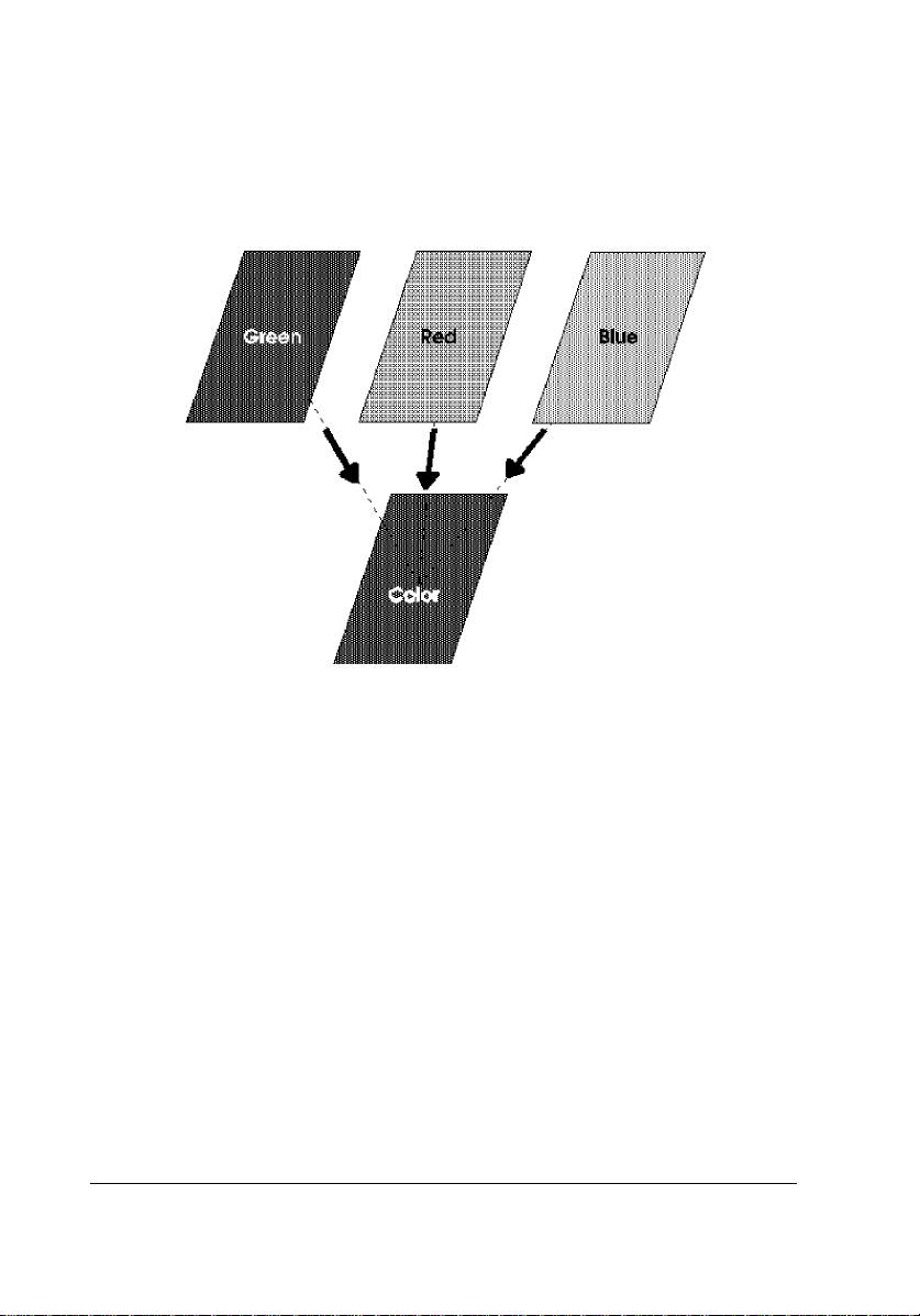
Reading color
By illuminating the document with three lights, red (R), green (G),
and blue (B), the scanner can analyze and separate a document’s three
color components. The computer can then overlay this color-separated
data to produce full-color images.
Reading monochrome
Even though you have a color scanner, you can still read your documents
as monochrome. Color scanners can read documents as monochrome in
two ways:
❏ Treat all the data on the page as the same color. This method uses
all the light sources, and is fine if you plan to print data in black
and white only.
❏ Specify one color (R, G, or B) as a dropout color. This method
uses only one light source and reads all data except for the color
specified.
1-4 Overview
Page 19

EPSON Scanner Features
EPSON scanners feature the following special attributes.
❏ A unified control code structure
All scanner features are controlled by EPSON’s ESC/I scanner
control codes, so the commands for each feature are the same for
all scanner models. All models are downwardly compatible, so
programs written for lower level scanners will work identically on
upper level scanners.
❏ Internal image data processing circuits
Each scanner contains circuitry capable of processing image data
before it is sent to the computer; the type of processing is
specified by control codes. By preprocessing image data, the
computer can process data faster with a reduction in image
distortion.
❏ Support of various interfaces
GT-1000: RS-232C Serial, Bi-directional Parallel
GT-4000: RS-232C Serial, Bi-directional Parallel,
SCSI (option)
GT-6000: RS-232C Serial, Bi-directional Parallel,
SCSI (option)
GT-8000: Bi-directional Parallel, SCSI
GT-6500: RS-232C Serial, Bi-directional Parallel, SCSI
GT-8500: Bi-directional Parallel, SCSI
GT-9000: Bi-directional Parallel, SCSI
GT-300: Bi-directional Parallel, SCSI
GT-5000: Bi-directional Parallel, SCSI
ES-300C: RS-232C Serial, Bi-directional Parallel,
SCSI (option)
ES-600C: Bi-directional Parallel, SCSI
ES-800C: Bi-directional Parallel, SCSI
ES-1000C: Bi-directional Parallel, SCSI
ES-1200C: Bi-directional Parallel, SCSI
ES-300GS: Bi-directional Parallel, SCSI
Action Scanner II Bi-directional Parallel, SCSI
Overview 1-5
Page 20

❏ Optional automatic document feeder
An automatic document feeder can be mounted on the GT-8000
(ES-800C), GT-6500 (ES-600C), GT-8500 (ES-1000C), or
GT-9000 (ES-1200C) scanner models, allowing you to
automatically load and scan multiple documents. This is
particularly useful when using OCR (Optical Character
Recognition) software to input text from long documents, or
when creating an image data base.
❏ Optional transparency illumination unit
This unit can read transparencies (film) when mounted on the
GT-8000 (ES-800C), GT-6500 (ES-600C), GT-8500 (ES-1000C),
or GT-9000 (ES-1200C) models. You can now scan film directly,
without having to first make a print of the film as was necessary
in the past. This allows for more accurate reading of film colors
with a minimum of degradation in image resolution. You can also
now directly read documents stored on film.
1-6 Overview
Page 21
Control Code Construction
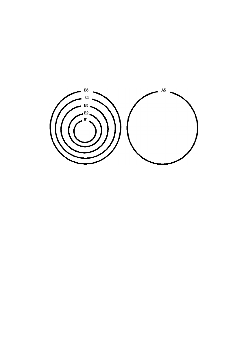
Function level
The EPSON image scanner control language currently has the
following function levels: B1 to B5 and A5. The relationship of each
level is shown in the following diagram. Each level contains the
commands and features of all lower levels.
For example, if you are using a B4-level scanner, all programs made
for B1 through B3 levels should run with no problem. All scanners
feature the control codes from lower level machines.
However, some scanner settings are unique to particular scanner
models, so you must take these into account when writing scanner
programs.
Parameters
Some commands require additional parameters. Commands that
require parameters do not take effect until the parameters are sent, so
always make sure you send the correct parameters. Sending an
incorrect parameter may cause a scanner error.
Overview 1-7
Page 22

Computers and Handshaking
Scanners are connected to their host computers by some kind of
interface. Since a scanner sends data to the computer, the interface
must carry data not only from the computer to the scanner, but also
from the scanner to the computer. For this reason, the interface must
be capable of bi-directional communication.
A method of interaction between the computer and scanners is
necessary to prevent the computer from sending data at the same time
the scanner is sending data. This interaction method is the basis for
governing scanner operation.
EPSON scanner and computer interaction is controlled by a method
called handshaking. After the computer sends data to the scanner, it
must wait for the proper reply from the scanner before sending more
data. Also, when the scanner sends data to the computer, it must wait
for the correct response from the computer before sending additional
data. Handshaking dictates the method of sending data and how the
data is acknowledged by both the computer and scanner.
1-8 Overview
Page 23
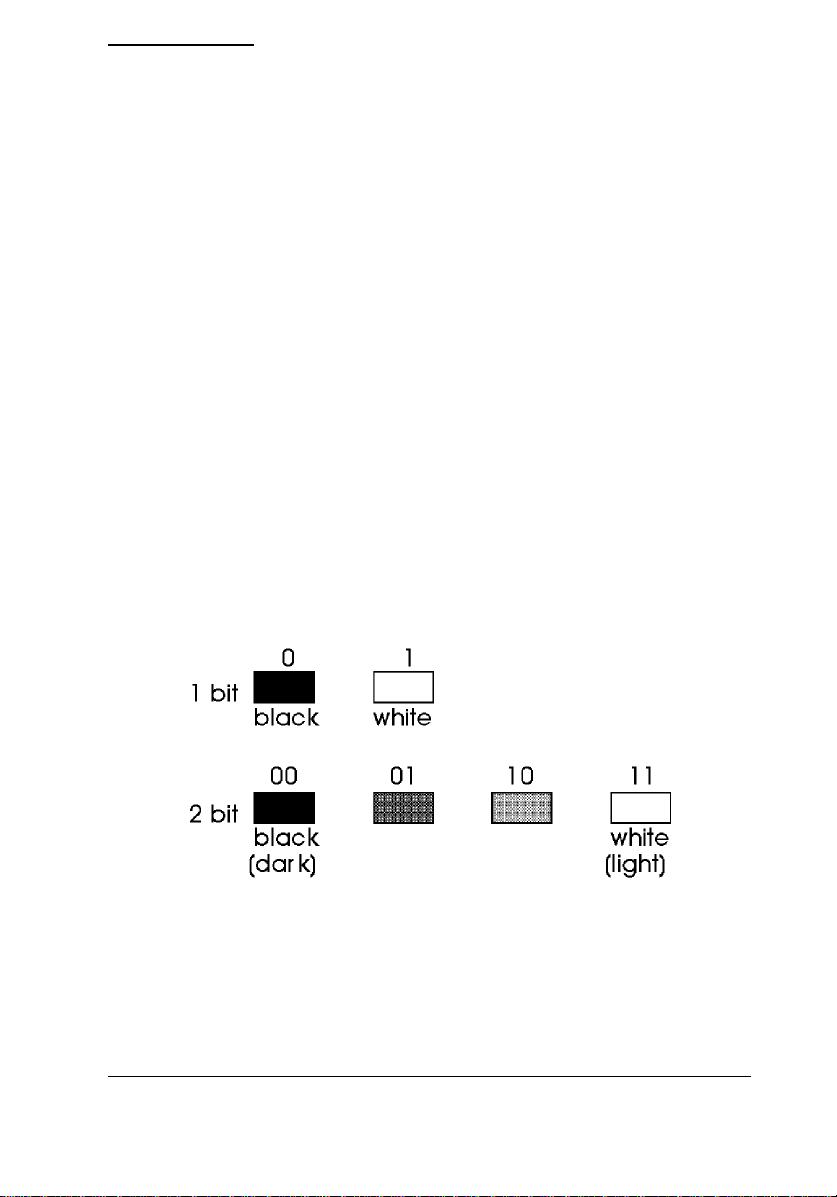
Image Data
The manner in which an image is converted into data and the way the
data is sent to the computer is predetermined. The following sections
describe this process.
Image data format
The smallest element of image data is called a pixel (short for picture
element). A pixel is an individual dot; combining these dots, or pixels,
forms an image.
If you represent each pixel by one bit of data, you can determine
whether that pixel is light or dark (1 or 0). This is called bi-level
conversion, and produces bilevel data.
However, most images contain a nearly infinite number of color
shades. By increasing the number of data bits per pixel, you can
increase the possible number of pixel shades you can represent. As
you can see from the following illustration, 1 bit per pixel allows you
to show only two shades; 2 bits per pixel allows you to represent up to
4 shades.
The image data format is what determines the amount of data
necessary for each pixel. The amount of data determines how many
shades you can express. Normally, you can select from 1 to 8 bits per
pixel. For monochrome scanning, this data determines the shade of
gray. For color scanning, you can differentiate the same number of
shades for each of three colors (green, red, and blue).
Overview 1-9
Page 24

As you increase the amount of data, you dramatically increase the
number of minute differences in color you can represent.
Bits per pixel Monochrome shades Colors
1 bit/color/pixel 2 8
2 bits/color/pixel 4 64
3 bits/color/pixel 8 512
4 bits/color/pixel 16 4,096
5 bits/color/pixel 32 32,768
6 bits/color/pixel 64 262,144
7 bits/color/pixel 128 2,097,152
8 bits/color/pixel 256 16,777,216
1-10 Overview
Page 25
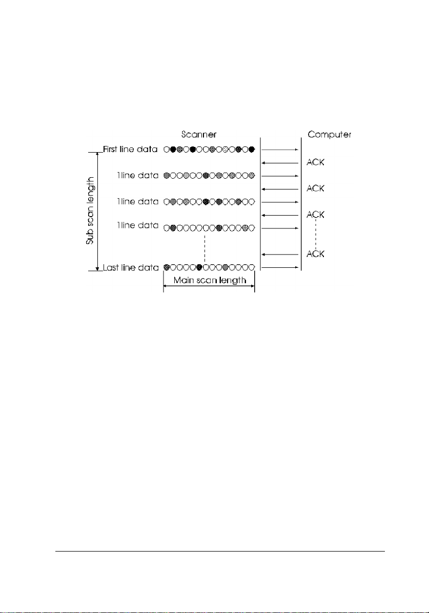
Line data transfer
The scanner reads one horizontal line of data (main scan) and sends it
to the computer. After the computer confirms it has received the data,
the scanner sends the next line of data. The scanner repeats theses
steps until data for the entire image is sent to the computer. This
method is called line data transfer.
Overview 1-11
Page 26
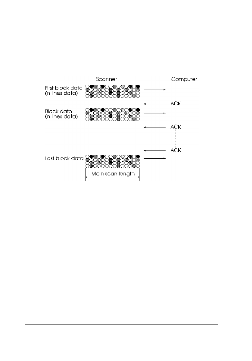
Block data transfer
Line data transfer sends the data to the computer line by line.
However, block data transfer sends multiple lines of data to the
computer all at once. You can use commands to specify the number of
lines sent at one time; in this way you can select the most efficient
block size to send your data.
1-12 Overview
Page 27
Functions
EPSON scanners feature a number of various functions. A brief
overview of these functions is provided below. For more detailed
explanations, see the following chapter on using these functions, as
well as the command reference section.
Image definition
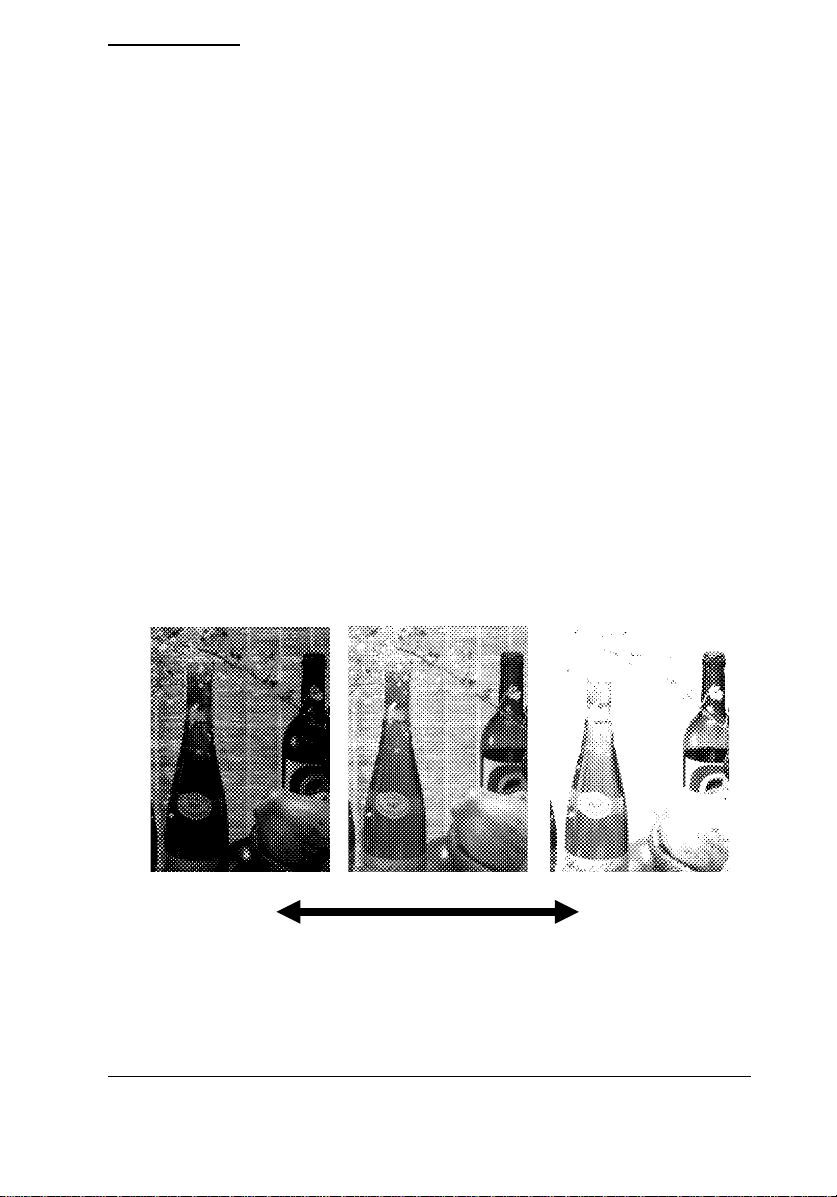
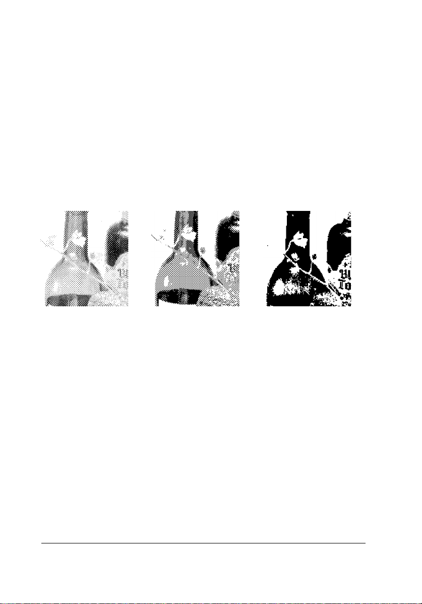
Brightness
This function allows you to set the brightness at which images are
scanned. The following illustration shows the difference this setting
can make in the final scanned image. Setting the brightness to a
brighter setting results in a bright image in which some thinner lines
may be washed out. On the other hand, setting brightness to a darker
setting results in a blacker image in which some intricate details may
turn out completely black.
Dark Bright
Overview 1-13
Page 28
Gamma correction
Gamma correction is a function that adjusts the light intensity so it
matches the output device.
Although an image may display clearly on your CRT display, your
printer may not produce it the same way. Since image reproduction
depends on the output device (CRT, printer, etc.), gamma correction
adjusts the light intensity so the image is faithfully reproduced on the
output device you are using. The term gamma refers to the ratio
between the input and output light intensity.
Display A Display B
Printer A Printer B Printer C
1-14 Overview
Page 29
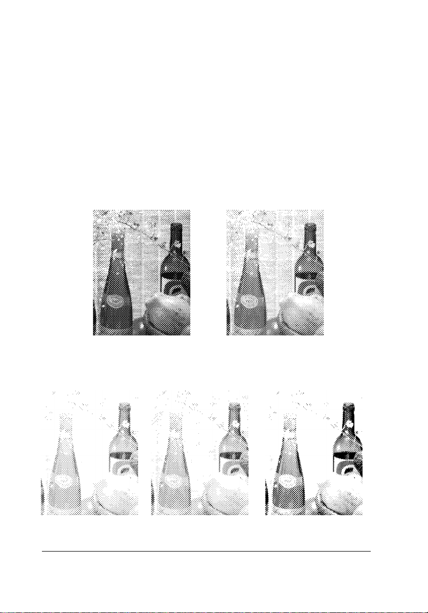
Halftoning
Halftoning adjusts the shade and color of each pixel according to the
shade and color of the surrounding pixels. Setting halftoning to large
results in a sharper contrast between dots. Setting halftoning to small
results in reduced contrast.
Overview 1-15
Page 30
Data form definition
Data format
The data format function determines how many bits are used to
represent one pixel. Increasing the bits increases the number of shades
and intensity that can be expressed. However, the data required to
represent an image is also increased. For example, to scan an A4 size
image using 8 bits per pixel at 300 dots per inch (dpi) in color would
require 26.4 MB of data.
Also, if your printer or CRT is not capable of expressing these
differences in color and shade, there is no reason to produce such
precise (and sizable data).
8 bit 2 bit 1 bit
1-16 Overview
Page 31

Resolution
The resolution determines how detailed a scan is. The resolution is
normally defined as the number of dots scanned per inch. The units of
resolution are dots per inch. You can also think of it as the density of
pixels in the image.
The greater the resolution, the greater the image detail you can scan.
However, the more detail you have, the greater the amount of data a
scan produces. For example, doubling the resolution in both the
horizontal and vertical directions results in four times the amount of
data.
Each output device also has its own specific resolution. If you scan an
image at the same resolution as your output device, the final image
will be the same size as the original. Likewise, if you scan an image at
double the resolution of your output device, the final image will be
twice the size of the original.
Note:
Some software may adjust images that include resolution information
so they appear as their actual size.
Overview 1-17
Page 32

Zoom
The zoom function causes an image scanned at the same resolution as
the output device to be output at a greater size than the original. The
zoom function can be set independently from the resolution setting.
Since the zoom function enlarges or shrinks the image of the original
document, the data amount expands or shrinks in response to the
zoom setting.
1-18 Overview
Page 33
Scanning area
The maximum scannable area for each scanner is determined by the
physical dimensions of the document table. You can also use
commands to tell the scanner to scan only a certain portion of your
document.
You set the scanning area in units of pixels. First set the point to begin
scanning, and then set the number of pixels beyond that point you
wish to scan.
Since you set these values as the number of pixels, using the zoom
function or changing the resolution affects the physical size of the
scanning area.
Overview 1-19
Page 34

Color setting
Setting the color determines the method used for scanning.
If you select monochrome scanning, you can specify either red (R),
green (G), or blue (B) as the dropout color. The scanner then ignores
the specified dropout color when scanning a document. For example,
if you want to read a document that has been marked with red pen,
you can select the dropout color to be red; the scanner then ignores the
red markings and scans only the original document.
If you select color scanning, you can choose page scanning, line
scanning, or byte scanning. Page scanning scans the entire page three
times; once for each color. Line scanning scans all three colors line by
line. Byte scanning scans byte by byte.
1-20 Overview
Page 35

Image processing
Halftoning
For documents with many shade gradations (like a photograph) in
full-color mode (24-bit data), you can faithfully reproduce the image
on a full-color output device. Some output devices, such as 8-color PC
monitors or 8-color printers, cannot faithfully portray a full-color
image; however, a method does exist for approximating multiple
shades on these types of output devices.
For example, by adjusting black and white pixels slightly,
you can approximate various shades of gray between black
and white. This type of data processing is called halftone processing,
and several versions are available on EPSON scanners. Two typical
forms of halftone processing are dither processing and density pattern
processing. Dither processing is the normal type of data processing
found on scanners. EPSON scanners also represent halftones using
dither processing.
Halftone mode A Halftone mode B
Overview 1-21
Page 36

Halftone mode C None
Dither mode A Dither mode B
Dither mode C Dither mode D
1-22 Overview
Page 37

Color correction
Colors expressed on different types of color output devices vary
slightly depending on each device’s characteristics. The color
correction feature allows you to adjust colors on output devices to
more closely approximate your original document.
Using Scanner Features
The scanner functions you use will vary, depending both on the type
of document you are scanning and the output device you plan to use.
This section describes which features are available for which types of
documents, as well as which features are available with which types
of output devices.
Scanning multiple shade documents for output on
devices capable of expressing multiple shades.
When you scan multiple shade documents (such as photographs or
pictures) and output them to devices capable of expressing multiple
shades (such as full-color computers or color film recorders), use the
following feature settings for best results.
Data format 3 to 8 bits/pixel/color
Image correction Method appropriate to output device
Data processing No
Overview 1-23
Page 38

Scanning multiple shade documents for bi-level output
devices capable of black and white only
When you scan multiple shade documents and output them to devices
capable of expressing only black and white, use the following feature
settings for best results.
Data format 1 bit/pixel/color
Image correction Method appropriate to output device
Data processing Yes
Scanning documents without multiple shades
When you scan line drawings, characters, logos, diagrams, etc., turn
all data and image processing off and scan the document. This allows
you to achieve the maximum contrast possible.
Data format 1 bit/pixel/color
Image correction Standard settings
Data processing No
Scanning documents to obtain unprocessed data
If you want to perform all data processing using your application
software, with no processing by the scanner, use the following feature
settings for best results.
Color setting Page scanning
Data format 8 bits/pixel/color
Image correction Standard settings
Brightness One step darker than standard
1-24 Overview
Page 39

Chapter 2
Command Usage
2
Command Usage 2-1
Page 40

Execution Commands
Execution commands tell the scanner to send back data to the
computer.
Use execution commands to begin image data transfer from the
scanner to the computer, to obtain the scanner ID and status, and to
obtain information on the current scanner settings.
1. Start scanning (ESC G)
Upon receiving this command, the scanner begins scanning and
sending image data to the computer. The scanner sends image data in
data blocks that consist of one or more lines.
After the computer receives a complete data block, it should send an
ACK code to the scanner to confirm receipt.
When the scanner receives the ACK code, it begins sending the next
data block.
This process is repeated over and over to continue sending data.
However, the computer should not send an ACK code after the final
data block.
To determine the final data block, refer to the status information block
at the beginning of each data block. See
page 2-28 for details on the status information block.
ESC G and other commands
The ESC G command begins scanning based on the current scanner
settings. Make sure you use the other commands to make your desired
settings before sending the ESC G command.
2-2 Command Usage
Page 41

2. Request ID (ESC I)
When the scanner receives this command, it relays the scanner ID
information to the computer in the following order.
Scanner command level
Available resolution values
Maximum scannable area
(at the highest resolution, with 100% zoom)
If you are creating a program for use with different scanner models,
you can use this command to determine the features and settings
available on the connected scanner model.
The ID information is transferred as a data block from the scanner to
the computer. See Appendix B for details on the ID information for
each scanner model.
3. Request Status (ESC F)
When the scanner receives the ESC F command, it sends a data block
to the computer that includes the status information. See page 2-28 for
details on status information. The length of the information block
within the data block is four bytes. The contents of these four bytes
are as follows:
Header (STX) 1 byte
Status 1 byte
Byte counter 2 bytes
4. Extended Status Request (ESC f)
Upon receiving this command, the scanner sends a data block to the
computer that includes the status of the scanner and any options
installed.
The data block is composed of the normal information block
combined with 33 bytes of extended status data.
Command Usage 2-3
Page 42
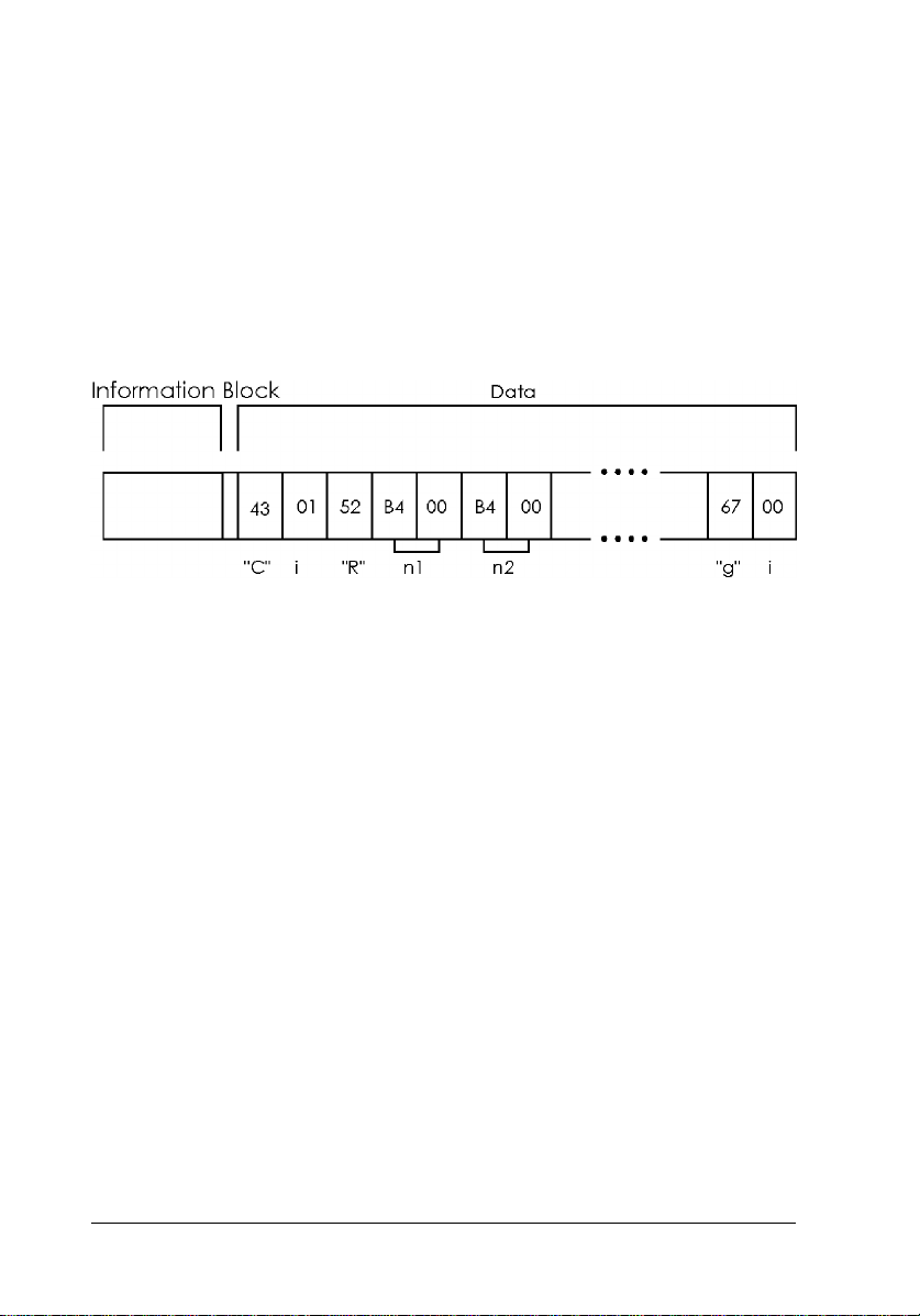
5. Request condition (ESC S)
This command causes the scanner to send a data block to the
computer that contains the current values of the settings for all the
scanner’s features.
The features available are different for each scanner model. Following
is a sample of a B4-level data block sent when the scanner receives
this command.
The ESC code and command code are ASCII character data. The 1 or
2 bytes of binary data that follow are that command’s setting
(parameter) value. Two-byte data is listed with the lower byte first and
the upper byte last.
2-4 Command Usage
Page 43

Data Form Commands
Data form commands regulate the amount of image data sent to the
computer (as determined by the setting for scanning color, resolution,
tone, and zoom).
1. Set Color Mode (ESC C)
This command sets either color or monochrome scanning.
If you select color scanning, you must specify page scanning, line
scanning, or byte scanning. Page scanning scans the entire page three
times; once for each color. Line scanning scans for each color on a
line-by-line basis. Byte scanning scans on a byte-by-byte basis.
If you select monochrome scanning, you can specify red, green, or
blue to be a dropout color.
ESC C and other commands
Selecting line scanning or byte scanning enables the use of the Color
Correction Command (ESC M).
2. Set Data Format (ESC D)
This command sets the number of bits available for representing each
color (green, red, and blue during color scanning). The number of bits
determines the number of shades that can be represented for each
color; the more bits, the more colors available. However, increasing
the number of shades available also increases the overall data required
to represent an image.
Command Usage 2-5
Page 44

For example, if you specify 8 bits per pixel for each color, the scanner
produces 8 bits of data per pixel per color. This requires eight times
the data necessary to represent 1 bit/pixel/color. As the number of bits
per color changes, the data format for each byte of data changes as
shown below:
ESC D and other commands
Halftone processing with the ESC B command is only available when
the number of bits/color/pixel is set to 1 or 2.
Setting the data format to 2 bits/color/pixel disables halftoning modes
B and C on the GT-1000, GT-4000, GT-6000, GT-6500, ES-300C,
and ES-600C. (You can select halftoning modes B and C, but mode A
processing takes place instead.) Selecting a data format of 3
bits/color/pixel disables all halftoning modes on all scanner models.
2-6 Command Usage
Page 45

3. Set Resolution (ESC R)
You can set different values for the resolution for the main scan
(horizontal direction) and the sub scan (vertical direction). You can
find the resolutions available by reading the scanner’s user’s manual
or, from within a program, sending the ID Request command.
ESC R and other commands
Multiple resolutions are available on all scanners. You can check the
resolutions available on the currently connected scanner by checking
the data block returned by the scanner when you send the ID Request
command. For B5- and A5-level scanners, you can select a resolution
from 50 dpi to the maximum available resolution of the scanner in
1-dpi increments. Trying to select a resolution that is not available
results in a command error.
This command determines the number of pixels that can be scanned
within the scanning area, based on the current zoom setting. Because
of this, you should always set the zoom and resolution before setting
the scanning area.
Even if your desired resolution is not available on the current scanner,
you can still adjust the zoom and resolution settings to approximate
your desired resolution. First set the resolution to the value closest to
your desired setting; then adjust the zoom until the resolution value
approximates your desired setting.
4. Set zoom (ESC H)
You can set the zoom (image enlargement/reduction) for the main
scan and sub scan independently, between the values of 50% to 200%.
After the scanning resolution is set, this command enlarges or reduces
the number of dots scanned, independent of the resolution. This
results in the scanned image being enlarged or reduced.
Command Usage 2-7
Page 46

Set zoom and other commands.
The combination of this command and the ESC R (Set resolution)
command determine the maximum number of dots you can scan. You
can calculate the number of dots by multiplying the zoom percent by
the original dot setting.
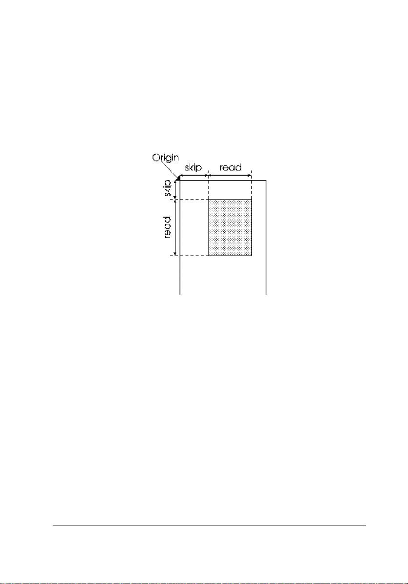
5. Set scanning area (ESC A)
This command selects the area to be scanned.
The main scan and sub scan are set in units of dots (in the current
resolution) measured from the origin. First you set the ‘‘skip distance’’
from the origin to the beginning of the main scan and sub scan. Then
you set the length of the main and sub scan as measured from the
point defined by the skip distance.
You must always set the main scan length in 8-dot units. However, the
skip distances and the sub scan length can be set in 1-dot units.
ESC A and other commands
Setting the resolution and zoom value determines the maximum
scannable area. You cannot set values that would exceed this
maximum scannable area.
6. Set data order (ESC K)
This command selects the order in which image data is scanned. You
can set the direction from left to right or from right to left.
2-8 Command Usage
Page 47

Image Setting Commands
Image setting commands are commands that tell the scanner what
kinds of image processing to perform on the image data. Brightness
settings and gamma correction (adjusting for input and output
brightness) settings are examples.
1. Set brightness (ESC L)
This command sets the scanning brightness. If the standard brightness
setting results in images that are too dark or light, use this command
to adjust the brightness. You can select from among seven brightness
levels; settings in between these seven levels are not possible.
The Set brightness (ESC L) command is ineffective when a gamma
table defined with the ESC z command is selected by the ESC Z (Set
gamma correction) command.
Command Usage 2-9
Page 48

2. Set gamma correction (ESC Z)
This command adjusts the scanned data according to the type of
output device you plan to use.
The gamma correction setting is independent of any other scanner
settings.
On B4 and higher-level scanners, you can use the ESC z command to
define gamma correction tables to match the unique needs of specific
types of documents and output devices.
Gamma correction processes data for various types of output devices
as explained below:
CRT Display A
This setting takes the scanned data and converts it directly to image
data. This is suitable for displays that are incapable of displaying
different tones of gray or color; for example, displays that can display
only 8 or 16 colors. This is also recommended for line or character
data that is scanned as bi-level data (1 bit/pixel/color).
2-10 Command Usage
Page 49

CRT Display B
This setting is suitable for 256-color displays and other displays that
are capable of showing multiple color levels. On these types of
displays, scanned data appears dark and grainy. CRT Display B
gamma correction processes the image data to appear more
continuous, improving its display appearance. On identical computers,
CRT Display B images appear brighter than CRT Display A images.
Printer Output A
This is the best choice for output on high-resolution printers (24-dot
matrix and laser printers). This type of correction processes image
data to appear more as individual dots, lightening the image. This type
of processed image may appear light or washed out when shown on a
computer display.
Printer Output B
Use this type of correction when printing out on low-resolution
printers (9-dot matrix). This type of output device produces images
that appear grainy; Printer Output B correction adjusts the data to
appear more continuous. The resulting image may appear light or
washed out on a computer screen. Also, Printer Output A images
appear lighter than Printer Output B images when output on the same
device.
Printer Output C
Use this type of processing when images and data are combined. If
you use this type of correction, black characters in an image appear
sharper, while illustrations are not affected.
Command Usage 2-11
Page 50

3. Download gamma table (ESC z)
Using this command, you can select the table used for gamma
correction. You can specify the type of output adjustment produced
for each of the 256 available color tones.
For example, to achieve the following type of image correction, you
can set the values determined by the equation below.
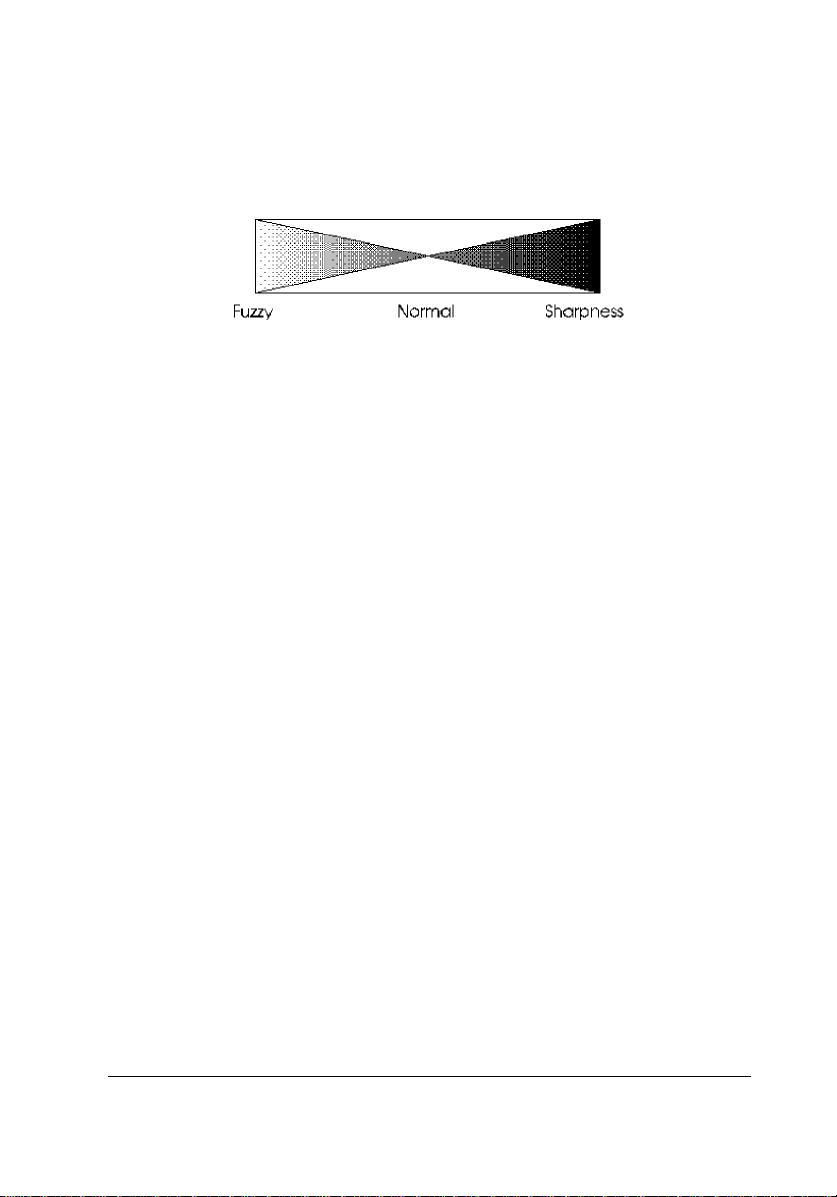
4. Set Sharpness (ESC Q)
This command is used to emphasize or de-emphasize the edges in
your images. Five settings are available. Emphasizing the edges of an
image makes it appear sharper. De-emphasizing the edges make it
appear softer. It is difficult to classify which images appear better with
which setting; you must match this setting to your particular document
and output device.
2-12 Command Usage
Page 51

Image Processing Commands
Image processing commands are used to modify scanned data before
sending it to the computer. Two commands are available: halftone
processing and color correction.
1. Set halftoning mode (ESC B)
This command enables or disables halftone processing for
bi-level data and quad-level data. The type of processing
performed is outlined below. However, the type of processing
available differs by scanner model. See Appendix B for details.
This command also enables or disables Text Enhancement
Technology. This function is only available for B5 or A5
command level scanners or higher.
❏ No data processing
Unprocessed data is sent directly to the computer. Use this setting
when scanning characters or line art that needs no processing.
❏ Halftoning mode A
Produces hard tones using the Error Diffusion method, producing
images with higher contrast. This is appropriate for most images.
❏ Halftoning mode B
Produces soft tones using the Error Diffusion method. This
method produces a softer image than halftoning
mode A.
❏ Halftoning mode C
Produces an image using a screen, again using the Error Diffusion
method.
❏ Dither mode A
Processes data using a 4×4 bayer pattern
Command Usage 2-13
Page 52

❏ Dither mode B
Processes data using a 4×4 spiral pattern
❏ Dither mode C
Processes data using a 4×4 screen pattern
❏ Dither mode D
Processes data using a 8×4 screen pattern
❏ User-defined modes A and B
Processes data using the pattern defined with the ESC b command
Built-in dither patterns
2-14 Command Usage
Page 53

ESC B and other commands
The scanner ignores the image processing you select with the ESC B
command if you have already selected 3 bits/color/pixel or higher
with the ESC D command.
2. Download dither pattern (ESC b)
This command defines the dither pattern that is selected when you use
ESC B to select user-defined dither patterns A and B. You can select
square patterns with sizes of 4×4, 8×8, and 16×16. You define the
dither pattern by assigning a threshold data value to each pattern
member. Since image data has a value from 0 to 256, you can set the
threshold value from 0 to 256.
The threshold values you define with this command remain in effect
until you turn off the scanner or redefine new values. The ESC @
(Initialize the scanner) command does not clear these values.
Command Usage 2-15
Page 54

To determine the data for a typical spiral dither pattern like the one
shown in figure a, multiply the threshold value by 16 and add 8; the
results are the values shown in figure b. The data is then sent in the
order shown in figure c.
3. Set color correction (ESC M)
Color correction adjusts the colors to match those available on your
output device.
The color produced by different output devices varies depending on
the method used to express color. You can use this command to
correct colors to match various output devices.
The following output devices can be selected with this command.
❏ Dot-matrix impact printers
Use for color impact printing.
❏ Thermal printers
Use for color thermal printing.
❏ Ink-jet printers
Use for color ink-jet printing.
2-16 Command Usage
Page 55

❏ CRT displays
Use for color CRT displays
❏ User defined setting
Use for your customized output.
❏ No color correction
ESC M and other commands
The ESC M command is effective only after you select color line
scanning or byte scanning with the ESC C command.
4. Download color correction (ESC m)
Using this command, you can set the data for color correction. The
scanner converts the color data in accordance with the data specified
by this command.
Command Usage 2-17
Page 56

Auxiliary Commands
Auxiliary commands are provided for physical operation of the
scanner. These commands include the reset command and option
operation commands.
1. Initialize the scanner (ESC @)
This command returns all scanner settings to their original values (the
values when the scanner is first turned on). The carriage returns to the
home position. However, the definitions created with the ESC b and
ESC z commands are not erased.
2. Set the scanning mode (ESC g)
You can select from two modes with this command: high-speed mode
and normal mode. The scanner is always in normal mode unless you
change it with this command. If you are scanning at 8 bits/pixel (in
monochrome) or 8 bits/color/pixel (in color) you must select normal
mode.
In high-speed mode, the scanner moves its sensor faster. This is useful
if a high degree of scanning precision is not required, or if you are
scanning bi-level data such as characters or line drawings.
2-18 Command Usage
Page 57

3. Set the line counter (ESC d)
Sending this command causes the scanner to send data in block
format. If you don’t send this command at the beginning of each job,
the scanner defaults to line mode and sends data after each line is
scanned.
You can set the parameter in this command from 1 to 255 lines. This
tells the scanner how many lines to send to the computer at a time. In
other words, setting the parameter to 10 results in the printer sending
scanned data in blocks 10-lines long. During line mode, the scanner
confirms that the computer receives each line of data after it is sent.
By sending data in blocks of multiple lines, you can save the time
required for line-by-line confirmation.
Setting the line counter with this command does not necessarily mean
the final data block will include that exact number of lines. Make sure
your program always checks the line counter value included in each
data block when receiving data. For example, if the value X is the
number of total lines you are scanning, the number of lines in the final
data block would be MOD[
remainder of the division operation.
ESC d and other commands
X
⁄
]. The operator MOD indicates the
i
If you select color line scanning with the ESC C command, you must
select a parameter for the ESC d command that is a multiple of 3.
Command Usage 2-19
Page 58

4. Control option (ESC e)
This command is effective only when an option has been installed on
the scanner. If you send these commands when no option is installed,
the scanner returns a NAK signal and a command error results.
You can check if an option is installed by either using the ESC f
command or by checking the option flag in the status byte.
When using the optional Automatic Document Feeder, you cannot
select color page scanning; you should always use the ESC C
command to select color line scanning, byte scanning, or monochrome
scanning.
If you send this command when using the optional Transparency Unit
or Automatic Document Feeder, the scannable area changes. Check
the extended status information to determine the new scannable area.
5. Eject (FF)
If you send this command when the Automatic Document Feeder is
installed, the scanner returns an ACK code and ejects the document
when scanning is completed.
Control Codes
These are commands that control data transfer.
1. Header (STX)
Send this code to indicate the beginning of a data block.
2-20 Command Usage
Page 59

2. Abort scanning (CAN)
Usually you send an ESC G command to start scanning and, after the
scanner sends a data block, the computer responds with an ACK code
to confirm the data was received. If the computer sends a CAN code
instead of the ACK code, the scanner cancels scanning and stops
sending data.
The scanner recognizes the CAN code only after it has sent a data
block and is waiting to receive the ACK code from the computer. If
the scanner receives the CAN code when it is waiting to receive a
command, a command error results.
After the scanner cancels scanning, the carriage returns to the home
position. Other scanner settings are not affected by canceling
scanning. Also, scanning does not resume at the position where it was
canceled.
3. Normal response (ACK)
When the scanner receives correct commands or parameters, it sends
this code to the computer as a kind of confirmation.
When sending image data, the computer should send an ACK code to
the scanner after it receives each data block. When scanning in color,
the computer should send an ACK code after each data block for each
color.
4. Negative response (NAK)
When the scanner receives an incorrect command or parameter, it
sends a NAK code. When the scanner sends this code, a command
error also results.
If the scanner returns a NAK code, the previously sent command is
not performed. If you were trying to change a scanner setting, the
previous setting remains in effect.
Command Usage 2-21
Page 60

Command Order
By using the Request ID (ESC I) command, you can determine the
scanner model. This allows you to create software that sends only the
commands featured on that particular model. Always check the
scanner ID before making settings with software commands.
The ID information consists of the following:
❏ The scanner function level
❏ The available scanner resolutions
❏ The maximum scannable area
The maximum resolution and maximum scannable area values are
used to determine the available parameters in the Set scanning area
(ESC A) command when zoom and resolution are changed.
ID information
1. Scanner function level
The scanner level indicates which commands are supported on the
connected scanner, allowing you to make full use of the scanner’s
features. You also can determine which commands are not available,
so you can avoiding causing command errors.
2. Available resolutions
All scanning resolutions available on the connected scanner are listed
in the ID information. All resolutions are available for both the main
scan and sub scan; the main scan and sub scan values can be set
independently from each other. The last resolution value is the highest
resolution available on the scanner.
2-22 Command Usage
Page 61

3. Maximum scannable area
This value is expressed in units of dots (main scan × sub scan), based
on the maximum scannable area available when the scanner is set to
the highest available resolution and zoom is set to 100%.
Control flow
Using the ID information, you should send commands to the scanner
in the following order.
1. Obtain the scanner’s ID information by sending the ESC I command.
2. After checking the scanner function level, send commands available
at that level to make the various scanner settings.
3. Refer to the resolution and maximum scannable area information in
the ID information and set the resolution, zoom, and scanning
area.
4. Start scanning.
To scan again, repeat steps 2 through 4 above.
Command Usage 2-23
Page 62

Recommended command order
Send commands in the following order to control the scanner
properly. Make sure to send the ESC R, ESC H, ESC A, and ESC G
commands in the following order.
ESC I Request ID
ESC e Control option
ESC C Set color
ESC D Set data format
ESC B Set halftoning mode
ESC L Set brightness
ESC Z Set gamma correction
ESC M Set color correction
ESC Q Set sharpness
ESC g Set the scanning mode
ESC K Set data order
ESC R Set resolution
ESC H Set zoom
ESC A Set scanning area
ESC d Set line counter
ESC G Start scanning
Using commands when options are installed
With scanners that are capable of using options, your programs should
always check the flag in the status byte to determine if options are
installed. Then use the following steps to operate the scanner.
1. Use the ESC I (Request ID) command to obtain the scanner’s ID
information. This information includes the scanner’s function
level, the scan resolutions available, and the maximum scannable
area.
2. Check bit 4 in the ID information status byte. If the bit is not set to
1, no option is installed and option use should be discontinued.
3. Send the ESC f (Request extended status) command to determine
the option’s maximum scannable area.
4. Send the ESC e (Control option) command and enable the option.
2-24 Command Usage
Page 63

5. Following the order on the previous page, send the command to set
the scanning area and send any other commands necessary to
prepare for scanning. For details on these commands, see Chapter
3.
6. Send the ESC f command. Check if the option is enabled and make
sure no error has occurred. In an error occurs, perform the proper
error recovery procedures.
7. Send the ESC G (Start scanning) command.
8. Receive the image data. If an error occurs during data reception, the
status byte’s error flag and area end flag are set to 1, and the byte
counter is set to 0; scanning then ends. After clearing the cause of
the error, send the ESC @ (Initialize the scanner) command to
reset the scanner and return to step 4.
9. After image scanning is complete, send the FF (Eject document)
command (only if you are using the ADF).
10. To repeat scanning, return to step 6.
11. If you don’t plan to use an installed option, always send the ESC e
command to disable the option before you begin scanning.
Command Usage 2-25
Page 64

Data Block Transfer Order
The computer sends commands and parameters to the scanner in 8-bit
code format. The scanner sends data to the computer in groups of
8-bit codes called ‘‘blocks.’’
Data block structure
Data blocks can take two forms: line data structure and block data
structure.
Note:
The scanner must support the ESC d (Set line counter) command and
be function level B4 or higher to transfer data using the block data
structure.
A data block consists of two parts: the first part contains a header and
status block; the second part is the scanned data extended.
Line data structure
Line data consists of a 4-byte information block followed by either an
ID information data, an extended status data, or one line of the main
scan image data.
The information block size is fixed at four bytes. The amount of data
following differs depending on the data type. The byte counter in the
information block specifies how much data is contained in the block.
2-26 Command Usage
Page 65

Block data structure
Block data consists of a 6-byte information block followed by n lines
of image data (n is the value of the line counter in the information
block).
You specify block data transfer with the ESC d (set line counter)
command. By sending multiple lines of data at once, you can shorten
the total data transfer time.
The information block size is fixed at 6 bytes. You can use the byte
counter and line counter in the information block to determine the
amount of data (number of bytes).
Information block
An information block is included in all data blocks; and provides
information on the beginning of the data block, the current state of the
scanner, and the length of the data that follows.
Header
This byte is always set to the STX code (02H), and indicates the
beginning of the data block.
Command Usage 2-27
Page 66

Status byte
This byte indicates the color of the image data or the state of the
scanner. Each bit in the Status byte has a different meaning, as shown
in the following diagram. Currently, bits 0, 1, and 6 are reserved (not
used).
Error flag (bit 7)
This flag is set to ‘‘1’’ when an error other than a command error
occurs. In this case, no data follows, so the byte counter is set to 0
(00H, 00H).
If a system error occurs, the scanner accepts only the ESC F and ESC
f commands. These two commands are used to determine if a system
error has occurred.
Area end flag (bit 5)
This flag is set to ‘‘1’’ when the data block is the final block of
scanned data in the scanning area. Do not send an ACK code to the
scanner after receiving the final data block (when this flag is set to 1).
Option flag (bit 4)
This flag is set to ‘‘1’’ when an option is installed.
2-28 Command Usage
Page 67

Scanning color (bits 2 and 3)
These bits indicate the scanning color. When monochrome is selected,
these bits indicate the dropout color (if a dropout color is selected).
Byte counter
The byte counter indicates the number of data bytes contained in each
data line. The counter consists of two bytes (an upper and lower byte);
the value of the counter is determined according to the following
formula:
(number of data bytes) = (lower byte) + (256 × (upper byte))
Make sure that your program checks the byte counter in each data
block and receives all data sent by the scanner. If the computer does
not accept all data, the scanner goes into a waiting state.
Line counter
When in block data transfer mode, this counter indicates the number
of lines of image data in the block. When in color line scanning mode,
data is organized in successive lines of green, red, and blue data (in
that order). Each color is counted as a separate line, so the line counter
must be a multiple of three. For example, n lines of color data result in
a line counter equal to 3n.
Command Usage 2-29
Page 68

Data
This is the data block following the information block. The type of
data in the data block depends on the type of information requested by
the computer.
Image data
Image data blocks sent in response to the ESC G (Start scanning)
command
ID information data
Data, including the scanner function level, sent in response to the ESC
I (Request ID) command
Scanner state data
Data on the scanner’s current settings and parameters sent in response
to the ESC S (Request condition) command
Extended status data
Data on the scanner’s option settings sent in response to the ESC f
(Request extended status) command
Note:
The data block sent in response to the ESC F (Request status)
command consists of the information block only; no data block is
included. Because of this, the byte counter is set to 0 (00H, 00H).
Use this command when you need to check only the contents of
the status byte.
Image data
This is the scanned image data sent in response to the ESC G (Start
scanning) command. The amount of data sent depends on the current
scanner settings.
The commands that determine the amount of data are the ESC D (Set
data format) command and the ESC A (Set scanning area) command.
ID information data
This is data sent in response to the ESC I (Request ID) command.
This data includes the following.
2-30 Command Usage
Page 69

The scanner function level
The available resolutions
The maximum scannable area
The basic format of this data is as follows:
The first two bytes show the scanner function level, in ASCII
character format. The scanner function level tells you which
commands are supported by the attached scanner.
Following these two bytes are the available scanner resolutions,
described in 3-byte groups. Multiple resolutions are listed, and the
available resolutions differ according to scanner model. The values
listed are the available values for the parameter in the ESC R (Set
resolution) command. The values listed can be assigned to both the
main scan and sub scan; the main scan and sub scan can be set
independently of one another. The final 5 bytes are the maximum
scannable area when the maximum resolution and 100% zoom are
selected. This value also varies by scanner model. This value, along
with the maximum resolution value, are the maximum parameters
available with the ESC A command.
Command Usage 2-31
Page 70

Scanner state data
This is the data sent in response to the ESC S (Request condition)
command. The example below is for a B4-level scanner.
The first two bytes are the ESC C (Set color) command’s parameters.
The next 5 bytes are the ESC R (Set scanning resolution) command’s
parameters.
The last two bytes are the ESC g (Set scanning mode) command’s
parameters.
Transfer order
The recommended order of data transfer for each type of data is
outlined in the flow charts below.
2-32 Command Usage
Page 71

Image data
Monochrome, color line, and color byte scanning
Use when sending monochrome and color line scanning data or color
byte scanning data. This includes monochrome scanning when a
dropout color is selected.
Command Usage 2-33
Page 72

Color page scanning
Use when sending color page data.
2-34 Command Usage
Page 73

Single data blocks
Use when you expect single data blocks in response to the ESC I
(Request ID) command, the ESC S (Request condition) command, the
ESC F (Request status) command, and the ESC f (Request extended
status) command.
Scanning Area
The following commands affect the scanning area: the ESC R (Set
resolution) command, the ESC H (Set zoom) command, and the ESC
A (Set scanning area) command. The parameter values in the ID
information are used in these commands. The relationship between
these commands and the scanning area is explained below.
Command Usage 2-35
Page 74

Resolution, zoom, and maximum scannable area
The ID information provides you the following values.
R
(in dpi) : The maximum scannable area available
MAX
X
(in dots) : The maximum main scan value (at the maximum
MAX
resolution, 100% zoom)
Y
(in dots) : The maximum sub scan value (at the maximum
MAX
resolution, 100% zoom)
Based on these values, you can calculate the maximum scannable area
for various resolution and zoom settings according to the following
formulas.
Main scan (in dots)
nx = INT
X
R
MAX
MAX
×
RX × H
100
X
Sub scan
ny = INT
Y
R
MAX
MAX
×
RY × H
100
Y
Based on these values, the limits of the parameters for the
ESC A command are as follows:
n1 (main scan skip length) : 0 ≤ n1 ≤ nx − 8
n2 (sub scan skip length) : 0 ≤ n2 ≤ ny − 1
n3 (main scan reading length) : 8 ≤ n3 ≤ 8 × INT
n4 (sub scan reading length) : 1 ≤ n4 ≤ ny − n
2
nx − n
1
8
n1 + n3 ≤ nx
n2 + n4 ≤ ny
Note:
The limits of the n3 parameter depend on your scanner model. See
your scanner’s manual for details.
2-36 Command Usage
Page 75

The main scan reading length (n3) must always be set in exact
multiples of eight (8-dot units equal units of 1 byte). The main scan
skip length (n1), sub scan skip length (n2), and sub scan reading length
(n4) can be set in 1-dot increments.
Use the above values to set the scanning area with the ESC R, ESC H,
and ESC A commands.
Note:
The ESC A command sets the length (number of lines) of the sub scan
reading length. However, you should always check the area end flag
in the status byte to confirm whether the current data block is the final
block. Do not rely solely on your calculations from the ESC A
command.
Command Usage 2-37
Page 76

Setting the scanning area
Use the ESC R, ESC H, and ESC A commands to set the scanning
area. The diagram below shows the relationship between the ESC R,
ESC H, and ESC A command parameters and the scanning area.
RX : Main scan resolution (in dpi)
RY : Sub scan resolution (in dpi)
HX : Main scan zoom (in %)
HY : Sub scan zoom (in %)
After setting the above values, determine the ESC A parameters based
on the following formulas:
2-38 Command Usage
Page 77

n1 = INT
LX1 × RX × H
100
X
n2 = INT
LY1 × RY × H
n3 = 8 × INT
L
≤ INT
3
≤ INT
4
Y2
n4 = INT
n1 + n
n2 + n
Y
100
L
× R
× H
X2
× RY × H
X
100
Y
1
X
×
8
100
maximum main scan length
maximum resolution
maximum sub scan length
maximum resolution
R
× H
X
× H
Y
100
100
X
Y
×
R
×
Command Usage 2-39
Page 78

Image trimming (1)
This section explains how to trim a rough image, and how to use the
ESC R, ESC H, and ESC A commands to rescan at the same
resolution and zoom values. This is useful when you want to check
the image from within your software and then reset the scanning area
for the next scan.
Rough scanned image Image after trimming
RX1 : Main scan resolution (dpi) RX2 : Main scan resolution (dpi)
RY1 : Sub scan resolution (dpi) R
: Sub scan resolution (dpi)
X2
HX1 : Main scan zoom (%) HX2 : Sub scan zoom (%)
HY1 : Sub scan zoom (%) H
: Sub scan zoom (%)
Y2
n1 : main scan skip length N1 : main scan skip length
n2 : sub scan skip length N2 : sub scan skip length
n3 : main scan reading length N3 : main scan reading length
n4 : sub scan reading length N4 : sub scan reading length
2-40 Command Usage
Page 79

Determining setting values after trimming
After trimming an image, you should resend the ESC A command
using the following parameters.
N1 = INT
n1 × RX2 × H
N2 = INT
n2 × RY2 × H
N3 = 8 × INT
N4 = INT
n4 × RY2 × H
N1 + N3 ≤ INT
N2 + N4 ≤ INT
R
× H
X1
R
× H
Y1
n3 × RX2 × H
RX1 × H
R
× H
Y1
(maximum main scan length)
(maximum sub scan length )
X2
X1
Y2
Y1
1
X2
×
X1
Y2
Y1
maximum resolution )
(
maximum resolution )
(
8
×
×
R
× H
X
100
R
× H
Y
100
X
Y
The parameters for the ESC R, ESC H, and ESC A command should
be set to the following.
ESC R : n
ESC H : i
ESC A : n
1
= H
1
1
= R
= N
n
= R
X2,
2
i
= H
X2,
2
, n2 = N2, n
1
Y2
Y2
= N
3
, n4 = N
3
4
Command Usage 2-41
Page 80

Image trimming (2)
This section explains how to use the ESC R, ESC H, and ESC A
commands to print a trimmed image on your printer.
Rough scanned image Printing size after trimming
RX1 : Main scan resolution (dpi) RPX : Printer resolution (dpi)
RY1 : Sub scan resolution (dpi) main scan (horizontal)
HX1 : Main scan zoom (%) RPY : Printer resolution (dpi)
HY1 : Sub scan zoom (%) sub scan (vertical)
Main scan skip length (inches): L
Sub scan skip length (inches): L
Main scan reading length (inches): L
X2
=
Sub scan reading length (inches): L
=
X1
=
Y1
n3 × 100
RX1 × H
=
Y2
RX1 × H
RY1 × H
X1
RY1 × H
2-42 Command Usage
n1 × 100
X1
n2 × 100
Y1
n4 × 100
Y1
Page 81

Determining the setting values for printing
Based on the size of the image you plan to print and on the resolution
of the printer, use the following formulas to determine the final
scanning settings.
X
=
X
=
Y
×
X × 100
L
X2
Y × 100
L
Y2
N2 = INT
1
N4 = INT
8
n2 × RPY × H
RY1 × H
n4 × RY2 × H
RY1 × H
RX × H
×
100
RY × H
×
100
Y
Y1
Y
Y1
X
Y
Main scan zoom (%): H
Sub scan zoom (%): H
N1 = INT
n1 × RPX × H
RX1 × H
N3 = 8 × INT
N1 + N3 ≤ INT
N2 + N4 ≤ INT
n3 × RPX × H
RX1 × H
(maximum main scan length)
(maximum sub scan length )
X
X1
X1
maximum resolution )
(
maximum resolution )
(
The parameter values for the ESC R, ESC H, and ESC A commands
then become as follows:
ESC R : n1 = RPX, n2 = R
PY
ESC H : i1 = HX, i2 = H
ESC A: n1 = N1, n2 = N2, n3 = N3, n4 = N
Y
4
Note:
On scanners that can respond to printers and other various output
devices, you can set the RPX and RPY values to match the horizontal
and vertical resolution of your target printer.
Command Usage 2-43
Page 82

Error Processing
EPSON scanners have four types of potential errors: command errors,
communications errors, system errors, and option errors. An option
error can occur only with scanner models
on which the optional Automatic Document Feeder or Transparency
Unit can be installed.
When an error occurs, the LED indicator displays the error type. For
details, see the scanner’s user’s manual.
Command error
This error occurs when the scanner receives an incorrect command or
a command with incorrect parameters.
Cause:
The scanner receives an undefined command.
The scanner receives a command with incorrect parameters.
Scanner’s response:
The scanner returns a NAK code to the computer, ignores the
incorrect command or parameters, and waits for the next command.
Error recovery procedure:
Send a correct command; the scanner then clears the error condition.
Communications error
A communication error occurs when the scanner and computer cannot
communicate properly.
Cause:
The interface is disconnected or not connected properly.
2-44 Command Usage
Page 83

The communications (interface) settings are incorrect.
Scanner’s response:
The lamps turn off and the scanner stops moving.
The scanner stops accepting commands.
Error recovery procedure:
After correcting the communications problem, perform one of the
following.
Turn the scanner off and then back on again.
Press the reset button (if the scanner model has a reset button).
Set the parallel interface’s INIT signal to LOW.
Send a device reset message on your SCSI line.
Set the SCSI’s reset line to active.
System error
The scanner itself is not functioning properly.
Cause:
The lamps are disconnected or burned out.
The shipping screw has not been removed from the carriage (the
scanner cannot perform the carriage initialization procedure).
The scanner is broken.
During scanning, an option error was detected (cover open, paper jam,
etc.).
Scanner’s response:
The lamps turn off and the scanner stops moving.
Command Usage 2-45
Page 84

Bit 7 (error flag) of the status byte is set to ‘‘1.’’
The appropriate bit in the extended status byte is set.
The scanner only accepts these commands: ESC F, ESC f, and ESC @.
Error recovery procedure:
After correcting the cause of the problem, perform one of the
following.
Turn the scanner off and then back on again.
Press the reset button (if the scanner model has a reset button).
Send the ESC @ command.
Set the parallel interface’s INIT signal to LOW.
Send a device reset message on your SCSI line.
Set the SCSI’s reset line to active.
Option error
When an option is installed and the ESC e (Control option) command
is enabled, this error occurs if the option does not operate properly.
Cause:
An option error is detected (cover open, paper jam, etc.).
Scanner’s response:
Bit 7 (error flag) of the status byte is set to ‘‘1.’’
The appropriate bit in the extended status byte is set.
Error recover procedure:
Correcting the cause of the error clears the error condition.
2-46 Command Usage
Page 85

Function Level and Commands
Each function level builds on the previous level, so all commands and
parameters in previous levels are included in higher levels. Extended
commands are available regardless of function level.
Using the function level
Higher function levels include all the commands of lower function
levels. Your programs should always check the function level of the
connected scanner and should send only those commands available on
that level.
Note:
All settings have initial default values, and some models have settings
that can be set using DIP switches or the control panel. However,
settings made using commands take precedence over these other
setting methods; to avoid errors and confusion, it is recommended you
make necessary settings using commands whenever possible.
Command Usage 2-47
Page 86

Commands and function level table
The following table shows which commands are available at each
function level.
Command type Command name Command Function
Level
Execution
commands
Data format
commands
Image setting
commands
Image processing
commands
Auxiliary commands Set scanning mode ESC g B4
* The parameters for these commands differ by function level.
Request ID ESC I B1
Request status ESC F B1
Request extended status ESC f Extended
Request condition ESC S B1
Start scanning ESC G B1
Set data format ESC D B1
Set resolution ESC R B1
Set zoom ESC H B2
Set scanning area ESC A B1
Set color ESC C B1*
Set data order ESC K B5, A5
Set brightness ESC L B2
Set gamma correction ESC Z B2*
Download gamma table ESC z B4
Set sharpness ESC Q B4
Set halftoning mode ESC B B1*
Download dither pattern ESC b B4
Set color correction ESC M B3
Download color correction ESC m B4
Set auto area segmentation ESC s A5
Set line counter ESC d B4
Control option ESC e Extended
Eject document FF Extended
Initialize the scanner ESC @ B2
Abort scanning CAN B1
2-48 Command Usage
Page 87

Function level and commands
The commands added at each function level are listed in the table
below.
Function level Command
B1 ESC G (Start scanning)
B2 ESC L (Set brightness)
B3 ESC M (Set color correction)
B4 ESC z (Download gamma table)
B5, A5 ESC K (Set data order)
A5 ESC s (Set auto area
ESC I (Request ID)
ESC F (Request status)
ESC S (Request condition)
ESC R (Set resolution)
ESC A (Set scanning area)
CAN (Abort scanning)
ESC D (Set data format)
ESC C (Set color)
ESC B (Set halftoning mode)
ESC Z (Set gamma correction)
ESC H (Set zoom)
ESC @ (Initialize the scanner)
ESC Q (Set sharpness)
ESC b (Download dither pattern)
ESC g (Set scanning mode)
ESC d (Set line counter)
ESC m (Download color correction)
segmentation)
Extended ESC f (Request extended status)
ESC e (Control option)
FF (Eject document)
Command Usage 2-49
Page 88

Items not affected by function level
Although higher command levels include all the previous commands
of lower command levels, the parameters for commands used to set
the scanning area (ESC R, ESC H, ESC A) are independent of
function level. These parameters are determined by the physical
characteristics of each scanner; obtain the values available for these
parameters by checking the ID information.
❏ Resolution
The resolutions available vary by scanner model and can be
obtained from the ID information returned by the scanner when
you send the Request ID command. If you use the ESC R
command to specify a resolution that is not available on the
connected scanner, a command error results. The last resolution
listed in the ID information is the maximum resolution available
on the connected scanner.
❏ Maximum scannable area
The maximum scannable area (# of main scan dots × # of sub
scan dots) you can set with the ESC A command differs by
scanner model. This value can be calculated from the maximum
resolution and maximum area values found in the ID information.
❏ Zoom setting increments (1% or 10%)
You can adjust the zoom value from 50% to 200%. However, the
minimum increment you can use to adjust the zoom value differs
by scanner model, and is either 1% or 10%. If you make a zoom
setting that is not a multiple of 10% on a scanner that only allows
10% increments, the scanner rounds the setting to the nearest
increment of 10%. (The scanner either corrects or deletes image
data to conform with the ESC A setting. Although this can result
in the image differing slightly from what you expect, you do not
need to take this into consideration within your program.)
❏ Options
To determine whether an option is installed on the connected
scanner, send the ESC F command and check the option flag in
the resulting status byte. You should also use the ESC f command
to determine the maximum scannable area when the option is
installed.
2-50 Command Usage
Page 89

Typical Programming Errors and Solutions
This section lists several concrete examples of programming errors,
their causes, and sample solutions to these problems.
Problem:
The scanner does not scan correctly when a scanner with a
different maximum scannable area is connected.
Cause
You relied on the default maximum scannable area
setting instead of setting the scanning area with the
ESC A command. The maximum scannable area
differs by scanner model.
Solution
Always set the scanning area with the ESC A
command.
Use the ESC I command to determine the current
scanner’s maximum scannable area, and make sure
the parameters in the ESC A command do not
exceed those values.
Command Usage 2-51
Page 90

Problem:
When connecting a different scanner model in your SCSI daisy
chain, an error message such as the following appears; ‘‘The
EPSON scanner is not connected.’’
Cause
When you sent the SCSI inquiry command, the
computer checked the scanner’s model name in the
Vendor Unique Parameter.
Solution
When checking the Vendor Unique Parameter, only
check the following underlined items:
...‘‘EPSON’’,20H,SCANNER,20H,‘‘GT-XXXX’’...
(B1−B4)
...‘‘EPSON’’,20H,20H,20H,SCANNER,20H,
‘‘GT-XXXX’’... (B5, A5)
This ensures that information on a particular model
name is not checked by your program.
Problem:
Although you have attached a new scanner capable of a higher
resolution, you cannot achieve that resolution when scanning.
Cause
Your program is still using the scanning resolution
settings you obtained from the previous scanner
model.
Solution
Use the ESC I command to obtain the scanning
resolution values each time you scan.
2-52 Command Usage
Page 91

Problem:
After connecting a scanner with a higher function level than the
previous scanner, the new scanner does not operate properly.
Cause
Although you used the ESC I command to obtain the
function level information, your program was set up
to work only when the function level was the same
as the previous scanner.
Solution
EPSON scanner function levels are designed so that
higher levels encompass all the commands of lower
levels. Change your program so it works with
scanners of equal level or higher.
Problem:
The speed of image data transfer remains the same, whether you
use a SCSI or bi-directional parallel interface.
Cause
Your program is writing each line of image data to
your hard disk as the data is received.
Solution
When using scanners of B4 level or higher, always
use block data transfer.
Command Usage 2-53
Page 92

Problem:
The scanner scans properly when you use a bi-directional
parallel interface, but when you switch to SCSI, the scanner no
longer operates properly.
Cause
During block data transfer mode, your program does
not read the entire block at one time, but performs
multiple read commands for each data block.
Solution
Change your program so it reads the entire block in
one read operation.
Problem:
After using a scanner option (Automatic Document Feeder or
Transparency Unit), a different program attempts scanning.
Although the second program tries to scan without using the
option, the option remains operational.
Cause
Your program did not exit option mode upon
completion.
Solution
Always exit option mode upon program completion.
2-54 Command Usage
Page 93

Problem:
When connecting a different scanner model, a
time-out occurs on your computer and you can no longer scan.
Cause
The time required for the initialization process and
for the preparation time when you send an ESC G
command differs by scanner model. The new
scanner model took longer than the previous scanner.
Solution
Make sure you provide enough time on your
time-out clock to handle all scanner models
(35 seconds should be enough).
Problem:
When writing data from a GT-6000 or GT-4000 to a
magneto-optical disk, an interface error occurs on the scanner.
Cause
On the GT-6000/4000, the scanner produces an
interface error if no handshake response is received
within 30 seconds. If a writing operation takes longer
than 30 seconds, this error occurs.
Solution
Adjust the size of your data buffer so that no writing
operation takes longer than 30 seconds.
Here are some additional items to consider when you write a scanner
program.
Command Usage 2-55
Page 94

General
❏ Always reset the scanner at the beginning and end of your
programs
❏ Use the ESC @ command to reset the scanner. This allows you to
use the same program with different interfaces.
❏ The time required for resetting differs by scanner model. Because
of this, you should either disable your computer’s time-out or set
the time-out clock to 30 seconds or more.
Parallel interface
❏ If your program sends a command immediately after resetting the
scanner and gets a BUSY signal, wait at least 1 ms and send the
command again.
Option
❏ Always send a FF command after you complete reading of a
document from an ADF.
Using the ESC I command
❏ Always check the scanner information at the beginning of your
program. (This is not necessary if you provide a different driver
for each scanner model.)
About the function level
❏ Since higher-level scanners contain all the functionality of
lower-level scanners, no errors occur when you use a low-level
scanner program on a higher-level scanner.
❏ When running a program designed for a high-level scanner on a
lower-level scanner, make sure your program does not send any
unsupported commands; otherwise, an error results.
2-56 Command Usage
Page 95

Chapter 3
Command Reference
Command Reference 3-1
3
Page 96

Summary of the Scanner Commands
Five types of scanner commands are used with EPSON scanners. In
addition, four control codes are used for handshaking. The five
command types are:
Execution: Requests the scanner to send
back data
Data form definition: Specifies the format of data to be
sent from the scanner
Image definition: Sets image modes
Image processing: Specifies any enhancement
processes to be used
Auxiliary: Helps control the scanner
Execution commands
These commands obtain data from the scanner.
Request ID ESC I
Request status ESC F
Request extended status ESC f
Request condition ESC S
Start scanning ESC G
Data form definition commands
These commands specify the format of image data and data transfer.
Set color ESC C
Set data format ESC D
Set resolution ESC R
Set zoom ESC H
Set scanning area ESC A
Set data order ESC K
3-2 Command Reference
Page 97

Image definition commands
Set conditions for image reading with these commands.
Set brightness ESC L
Set gamma correction ESC Z
Download gamma table ESC z
Set sharpness ESC Q
Image processing commands
Process images before data transfer with these commands.
Set halftoning mode ESC B
Download dither pattern ESC b
Set color correction ESC M
Download color correction ESC m
Set auto area segmentation ESC s
Supplemental commands
Operate the scanner mechanism with these commands.
Initialize the scanner ESC @
Set line counter ESC d
Set scanning mode ESC g
Control option ESC e
Eject document FF
Control codes
Perform handshaking between the computer and scanner using these
commands.
Header STX
Abort scanning CAN
Normal response ACK
Abnormal response NAK
Command Reference 3-3
Page 98

Format of the Command Reference
The command explanations in this chapter are each divided into six
parts. The command explanations are given in the sequence indicated
in the command summary table on the preceding page. (For
recommendations on how to use the commands, see Chapter 2.)
Command title
Indicates the name and function of the command
Command format
Shows the structure of the command and any associated parameters
Command: Shows the command code sequence in ASCII, decimal,
and hexadecimal formats
Parameter: Lists parameters, if applicable
Some commands require parameters to be sent after the command has
been accepted by the scanner. Commands and parameters are listed
separately if the handshaking method requires they be sent separately.
Parameters denoted by n are two-byte parameters (ranging from 0 to
65,535 decimal), with the lower byte preceding the higher byte.
Where necessary, the lower byte is denoted by L and higher byte by H.
Parameters denoted by i are one-byte parameters (ranging from 0 to
255 decimal).
Parameters denoted by d are signed one-byte parameters (ranging
from -127 to 127 decimal).
3-4 Command Reference
Page 99

Handshaking
Shows a diagram indicating the handshaking method used with the
command. See Chapter 2 for details on handshaking.
Parameter range
Shows the range and explains the meanings of parameters, when
relevant. This section also lists the default values.
Explanation
This gives a detailed explanation of the effect and appropriate usage
of the command.
Functional level
Lists values such as B1 and B4 on the command line and in the
parameter range to indicate the ESC/I function level of the command.
See Chapter 2 for details.
Command Reference 3-5
Page 100

Execution Commands
ESC I Request identity
Format: B1 B2 B3 B4 B5 A5
Command:ASCII: ESC I
Decimal: 27 73
Hexadecimal: 1B 49
Parameter: (none)
Handshaking:
1 ESC I command
2 data block
Explanation:
This command requests the scanner to send back a data block that
identifies the properties of the scanner. When this command is
received, the scanner sends the following information.
❏ The scanner’s functional level identification
❏ The resolution settings available
❏ The maximum scannable area at the maximum resolution and
100% zoom (main scan by sub scan in dots)
3-6 Command Reference
 Loading...