

Page 1
SERVICE MANUAL
Large Format Color Inkjet Printer
Epson Stylus Pro GS6000
Confidential
SEIJ08001
Page 2

Notice:
All rights reserved. No part of this manual may be reproduced, stored in a retrieval system, or transmitted in any form or by any means, electronic,
mechanical, photocopying, recording, or otherwise, without the prior written permission of SEIKO EPSON CORPORATION.
The contents of this manual are subject to change without notice.
All effort have been made to ensure the accuracy of the contents of this manual. However, should any errors be detected, SEIKO EPSON would greatly
appreciate being informed of them.
The above not withstanding SEIKO EPSON CORPORATION can assume no responsibility for any errors in this manual or the consequences thereof.
EPSON is a registered trademark of SEIKO EPSON CORPORATION.
General Notice: Other product names used herein are for identification purpose only and may be trademarks or registered trademarks of their
respective owners. EPSON disclaims any and all rights in those marks.
Copyright © 2008 SEIKO EPSON CORPORATION.
Imaging Products CS, PL & Environmental Management
Confidential
Page 3

PRECAUTIONS
Precautionary notations throughout the text are categorized relative to 1) Personal injury and 2) Damage to equipment.
DANGER Signals a precaution which, if ignored, could result in serious or fatal personal injury. Great caution should be exercised in performing
procedures preceded by DANGER Headings.
WARNING Signals a precaution which, if ignored, could result in damage to equipment.
The precautionary measures itemized below should always be observed when performing repair/maintenance procedures.
DANGER
1. ALWAYS DISCONNECT THE PRODUCT FROM THE POWER SOURCE AND PERIPHERAL DEVICES PERFORMING ANY MAINTENANCE OR
REPAIR PROCEDURES.
2. NO WORK SHOULD BE PERFORMED ON THE UNIT BY PERSONS UNFAMILIAR WITH BASIC SAFETY MEASURES AS DICTATED FOR ALL
ELECTRONICS TECHNICIANS IN THEIR LINE OF WORK.
3. WHEN PERFORMING TESTING AS DICTATED WITHIN THIS MANUAL, DO NOT CONNECT THE UNIT TO A POWER SOURCE UNTIL
INSTRUCTED TO DO SO. WHEN THE POWER SUPPLY CABLE MUST BE CONNECTED, USE EXTREME CAUTION IN WORKING ON POWER
SUPPLY AND OTHER ELECTRONIC COMPONENTS.
4. WHEN DISASSEMBLING OR ASSEMBLING A PRODUCT, MAKE SURE TO WEAR GLOVES TO AVOID INJURY FROM METAL PARTS WITH
SHARP EDGES.
WARNING
1. REPAIRS ON EPSON PRODUCT SHOULD BE PERFORMED ONLY BY AN EPSON CERTIFIED REPAIR TECHNICIAN.
2. MAKE CERTAIN THAT THE SOURCE VOLTAGES IS THE SAME AS THE RATED VOLTAGE, LISTED ON THE SERIAL NUMBER/RATING
PLATE. IF THE EPSON PRODUCT HAS A PRIMARY AC RATING DIFFERENT FROM AVAILABLE POWER SOURCE, DO NOT CONNECT IT TO
THE POWER SOURCE.
3. ALWAYS VERIFY THAT THE EPSON PRODUCT HAS BEEN DISCONNECTED FROM THE POWER SOURCE BEFORE REMOVING OR
REPLACING PRINTED CIRCUIT BOARDS AND/OR INDIVIDUAL CHIPS.
4. IN ORDER TO PROTECT SENSITIVE MICROPROCESSORS AND CIRCUITRY, USE STATIC DISCHARGE EQUIPMENT, SUCH AS ANTI-STATIC
WRIST STRAPS, WHEN ACCESSING INTERNAL COMPONENTS.
5. REPLACE MALFUNCTIONING COMPONENTS ONLY WITH THOSE COMPONENTS BY THE MANUFACTURE; INTRODUCTION OF SECONDSOURCE ICs OR OTHER NON-APPROVED COMPONENTS MAY DAMAGE THE PRODUCT AND VOID ANY APPLICABLE EPSON WARRANTY.
6. WHEN AIR DUSTER IS USED ON THE REPAIR AND THE MAINTENANCE WORK, THE USE OF THE AIR DUSTER PRODUCTS CONTAINING
THE INFLAMMABLE GAS IS PROHIBITED.
Confidential
Page 4
About This Manual
This manual describes basic functions, theory of electrical and mechanical operations, maintenance and repair procedures of the printer. The instructions and procedures included
herein are intended for the experienced repair technicians, and attention should be given to the precautions on the preceding page.
Manual Configuration
This manual consists of six chapters and Appendix.
CHAPTER 1.PRODUCT DESCRIPTIONS
Provides a general overview and specifications of the product.
CHAPTER 2.OPERATING PRINCIPLES
Describes the theory of electrical and mechanical operations of the
product.
CHAPTER 3.TROUBLESHOOTING
Describes the step-by-step procedures for the troubleshooting.
CHAPTER 4.DISASSEMBLY / ASSEMBLY
Describes the step-by-step procedures for disassembling and assembling
the product.
CHAPTER 5.ADJUSTMENT
Provides Epson-approved methods for adjustment.
CHAPTER 6.MAINTENANCE
Provides preventive maintenance procedures and the lists of Epsonapproved lubricants and adhesives required for servicing the product.
CHAPTER 7.APPENDIX
Provides the following additional information for reference:
• Connectors
• ASP List
• Exploded Diagrams
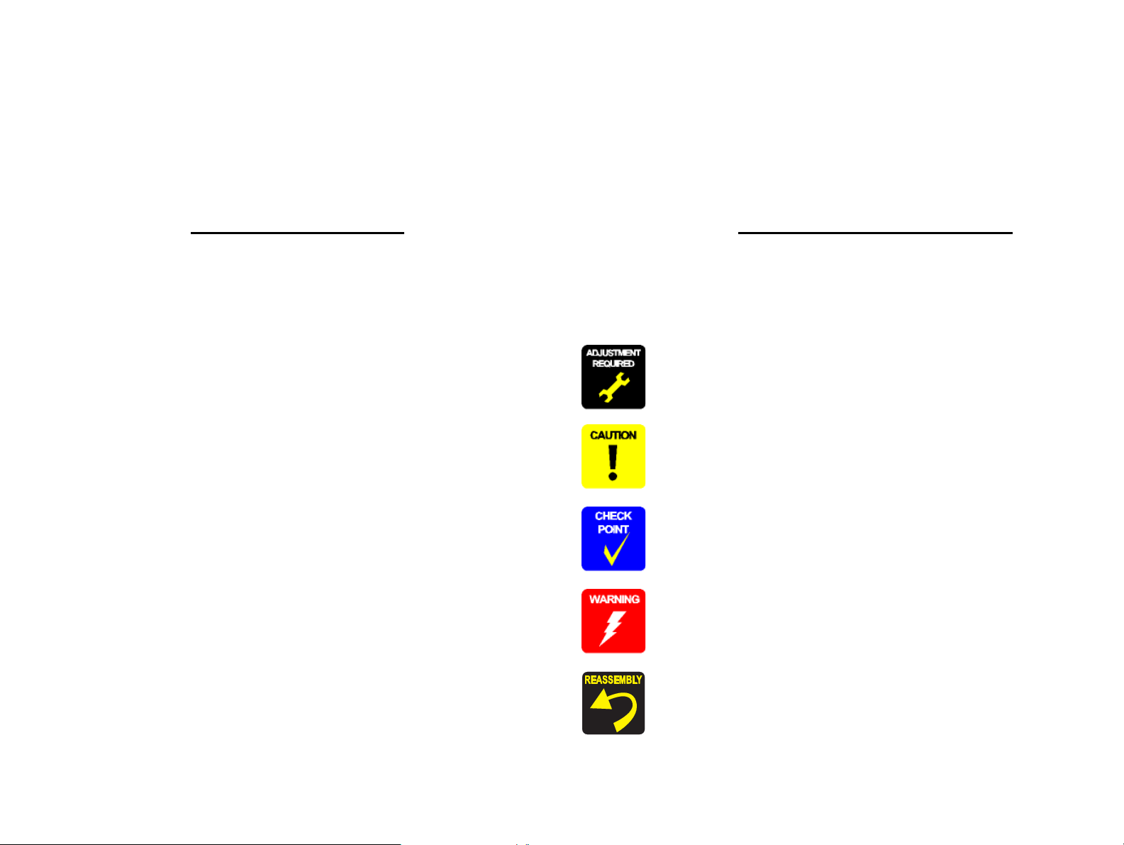
Symbols Used in this Manual
Various symbols are used throughout this manual either to provide additional
information on a specific topic or to warn of possible danger present during a
procedure or an action. Be aware of all symbols when they are used, and always read
NOTE, CAUTION, or WARNING messages.
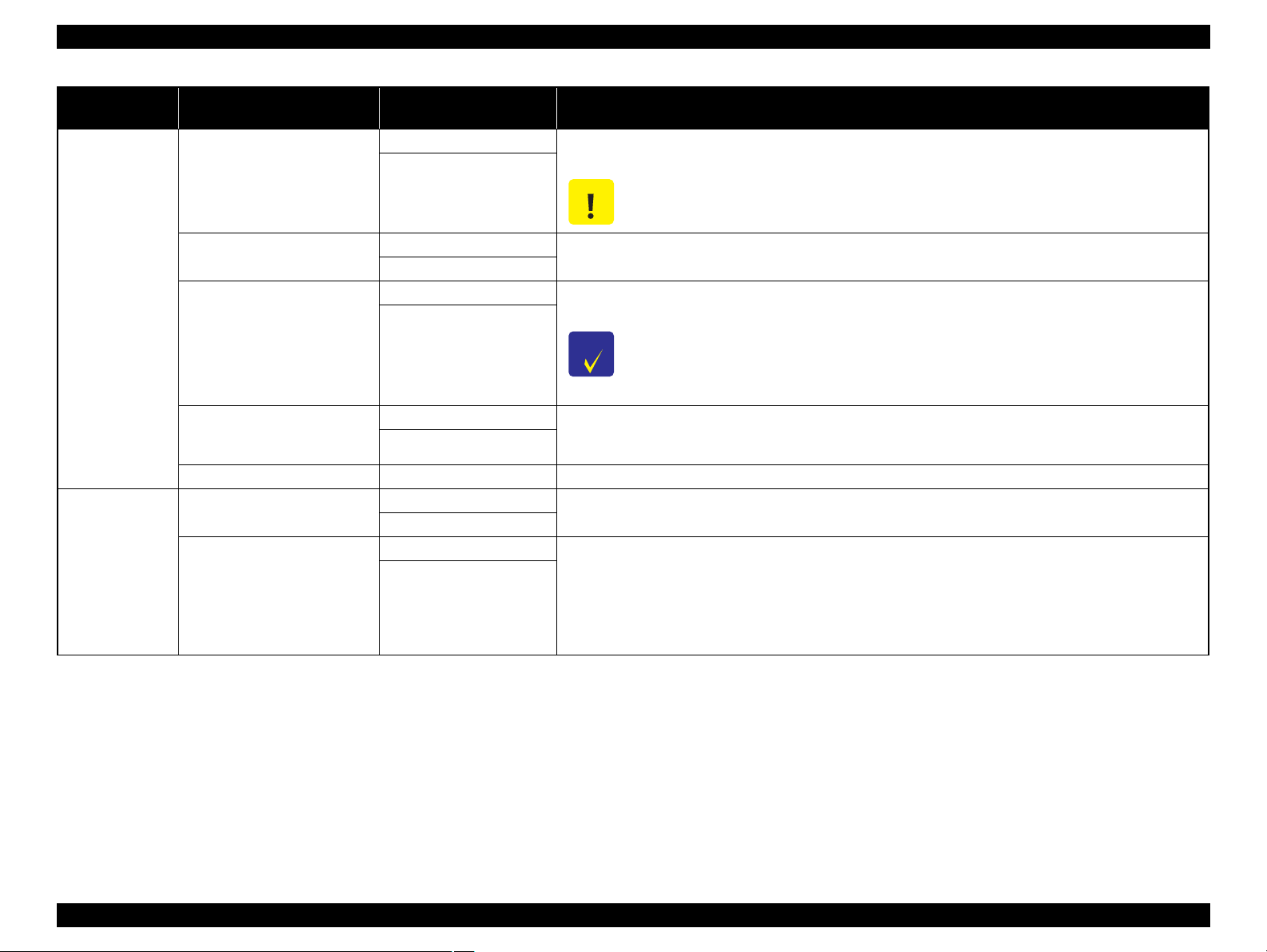
Indicates an operating or maintenance procedure, practice or condition
that is necessary to keep the product’s quality.
Indicates an operating or maintenance procedure, practice, or condition
that, if not strictly observed, could result in damage to, or destruction of,
equipment.
May indicate an operating or maintenance procedure, practice or
condition that is necessary to accomplish a task efficiently. It may also
provide additional information that is related to a specific subject, or
comment on the results achieved through a previous action.
Indicates an operating or maintenance procedure, practice or condition
that, if not strictly observed, could result in injury or loss of life.
Indicates that a particular task must be carried out according to a certain
standard after disassembly and before re-assembly, otherwise the quality
of the components in question may be adversely affected.
Confidential
Page 5

Revision Status
Revision Date of Issue Description
A July 18, 2008 First release
B December 12, 2008 Ch1:
1.2.2 Durability (p. 16)
Revised contents.
1.4.2 Panel Settings (p. 24)
Added the ROLL PAPER COUNTER menu.
1.4.3 Maintenance Mode (p. 32)
Added the REMAINING PPR SETUP menu.
1.4.4 Serviceman Mode (p. 33)
Added the menu list.
Ch4:
4.1.3 Recommended Tools (p. 66)
Added Thread-locker.
Ch5:
5.1.4 Tools for Adjustments (p. 191)
Added Thread-locker.
5.1.5 Service Program Basic Operations (p. 192)
Changed the explanation partially.
5.3.3 CR Height Adjustment (p. 204)
Corrected the values indicating the jig’s thickness.
5.4.6 Head Slant and Alignment Adjustment (p. 212)
Changed the explanation.
5.6.1 RTC and USB ID (p. 224)
Changed the explanation.
5.8.3 Electric Components Test (p. 236)
Changed the actions of the F COVER and the M COVER when checking partially.
Ch6:
6.4 Cleaning (p. 246)
Added the Carriage Rail Cleaner and the Carriage Rail Oil to the Maintenance Kit.
6.5 Lubrication (p. 253)
Added the Part No. of grease.
Confidential
Page 6

Revision Date of Issue Description
B December 12, 2008 Ch7:
7.3 Parts List (p. 262)
Update the information to the latest.
7.4 Exploded Diagram (p. 267)
Update the information to the latest.
C June 5, 2009 Ch3:
3.3 Remedies for Maintenance Requests (p. 54)
Added a table.
3.4 Remedies for Service Call Error (p. 55)
Added the Debug error.
Ch4:
4.1.1 Precautions (p. 64)
Changed the warnings partially.
4.1.3 Recommended Tools (p. 66)
Changed the length of Hexagonal wrench.
4.4.9.6 LOWER BEARING (p. 152)
Added the disassembling/reassembling procedures.
Ch5:
5.1.4 Tools for Adjustments (p. 191)
Added 1000mm Ruler.
5.1.5 Service Program Basic Operations (p. 192)
Changed the name.
5.2 NV-RAM BACKUP UTILITY (p. 198)
Changed the steps of Restore Procedure.
5.8.2 CR Durability Test (p. 235)
Added the section.
Ch6:
6.5 Lubrication (p. 253)
Added the caution.
6.5 Lubrication (p. 253)
Change the name of grease.
6.5 Lubrication (p. 253)
Added the amount of lubricant.
Confidential
Page 7

Revision Date of Issue Description
D September 18, 2009 Ch1:
Ink set configuration (p. 14)
Added the Ink Set Configuration.
Ch5:
5.3.2 CR Reduction Belt Tension Adjustment (p. 201)
Added the procedure.
E January 15, 2010 Ch4:
4.1.1 Precautions (p. 64)
Changed the cautions partially.
4.4.6.3 MAIN BOARD ASSY (p. 110)
Modified the adjustment.
4.4.11.11 CR CURSOR ASSY (p. 175)
Modified the adjustment.
4.4.9.2 CR REDUCTION BELT (p. 144)
Modified the adjustment.
4.4.9.5 CR MOTOR (p. 151)
Modified the adjustment.
4.4.11.1 PRINT HEAD/VALVE ASSEMBLY, HEAD (p. 158)
Modified the adjustment.
Ch5:
5.1.2 Adjustment Items and the Order by Repaired Part (p. 186)
Changes partially.
5.6.4.1 IP Address Setup (p. 228)
Added the adjustment.
5.6.4.2 Network Test (p. 228)
Changed.
5.6.5 NVRAM CLEAR OK (p. 229)
Added the adjustment.
5.6.6 Rear Sensor Test/Rear AD Adjustment (p. 230)
Added the adjustment.
5.6.7 Input Serial Number (p. 231)
Added the adjustment.
5.6.8 CR Origin Adjustment (p. 232)
Added the adjustment.
5.3.2 CR Reduction Belt Tension Adjustment (p. 201)
Changed the procedure. Added the Video. (Chapter 8)
Confidential
Page 8
Revision Date of Issue Description
F December 12, 2011 Ch5:
5.3.3 CR Height Adjustment (p. 204)
Change the Figure 5-20.
Ch5:
6.5 Lubrication (p. 253)
Change Grease type.
Confidential
Page 9

Epson Stylus Pro GS6000 Revision F
Contents
Chapter 1 PRODUCT DESCRIPTION
1.1 Features ............................................................................................................... 12
1.2 Basic Specifications ........................................... ... ....................................... ... .... 13
1.2.1 Printer Specifications ................................................................................. 13
1.2.2 Durability ................................................................................................... 16
1.2.3 Paper size/Printable area ............................................................................ 16
1.2.4 Print Mode / Print Resolution .................................................................... 17
1.3 Dimensions and Main Components ............................................... ..................... 18
1.3.1 Dimensions and Weight ........................................................... .................. 18
1.3.2 Part Names ................................................................................................. 19
1.4 Control Panel .............................................................. ....................................... . 20
1.4.1 Buttons and Indicators ............................................................................... 20
1.4.2 Panel Settings ............................................ ........................................ ......... 24
1.4.3 Maintenance Mode .................................................................................... 32
1.4.4 Serviceman Mode ...................................................................................... 33
Chapter 2 OPERATING PRINCIPLES
2.1 Glossary .............................................................................................................. 41
2.2 Ink System ............................................................ ....................................... ....... 42
2.3 Carriage Mechanism ........................................................................................... 43
2.4 Paper Feed Mechanism ....................................................................................... 44
2.5 Heater Mechanism ..................................... ....................................... .................. 45
2.6 Boards ................................................................................................................. 46
2.7 Sensors ................................................................................................................ 47
2.8 Fans ..................................................................................................................... 48
3.1.2 Troubleshooting Procedure ........................................................................ 50
3.2 Remedies for Error Messages ............................................................................. 51
3.3 Remedies for Maintenance Requests ............................ ..................................... 54
3.4 Remedies for Service Call Error ........................................................................ 55
3.5 Remedies for Print Quality Troubles .............................................. ... ................. 60
Chapter 4 DISASSEMBLY & ASSEMBLY
4.1 Overview ................................................ ........................................ ... ................. 64
4.1.1 Precautions ................................................................................................. 64
4.1.2 Orientation Definition ................................................................................ 66
4.1.3 Recommended Tools ................................................................................. 66
4.2 Parts Diagram ..................................................................................................... 67
4.3 Disassembly Flowchart ...................................................................................... 76
4.4 Disassembly and Assembly Procedure ............................................................... 83
4.4.1 Basic Operations ........................................................................................ 83
4.4.2 Consumables/Accessories ............................................................. ............ 84
4.4.3 Housing ...................................................................................................... 85
4.4.4 Electric Components .................................................................................. 99
4.4.5 Fans ...................................................... ....................................... ............. 101
4.4.6 Boards ....................................................................................... ............... 109
4.4.7 Sensors ................................ ..................................................................... 123
4.4.8 Heaters/Thermistors ................................................................................. 137
4.4.9 Carriage Mechanism ................................................................................ 142
4.4.10 Paper Feed Mechanism .......................................................................... 155
4.4.11 Ink System Mechanism ......................................................................... 158
4.4.12 Take-Up Reel Unit ................................................................................. 177
Chapter 3 TROUBLE SHOOTING
3.1 Overview ............................................................................................................ 50
3.1.1 Preliminary Check ..................................................................................... 50
Chapter 5 ADJUSTMENT
5.1 Overview ................................................ ........................................ ... ............... 185
5.1.1 Precautions ............................................................................................... 185
5.1.2 Adjustment Items and the Order by Repaired Part .................................. 186
9
Confidential
Page 10

Epson Stylus Pro GS6000 Revision F
5.1.3 Description of Adjustments ..................................................................... 189
5.1.4 Tools for Adjustments ............................................................................. 191
5.1.5 Service Program Basic Operations .......................................................... 192
5.1.6 Cautions and Preparation for Pattern Printing ......................................... 197
5.2 NV-RAM BACKUP UTILITY ........................................................................ 198
5.3 CR Related Adjustments .................................................................................. 199
5.3.1 CR Belt Tension Adjustment ................................................................... 199
5.3.2 CR Reduction Belt Tension Adjustment ................................................. 201
5.3.3 CR Height Adjustment ............................................................................ 204
5.3.4 Media Side Margin Adjustment ............................................................... 206
5.4 Head Related Adjustments ............................................................................... 207
5.4.1 Head Rank Input ...................................................................................... 207
5.4.2 Nozzle Check Pattern .............................................................................. 208
5.4.3 Cleaning and Washing ............................................................................. 209
5.4.4 Ink Discharge ........................................................................................... 210
5.4.5 Initial Ink Charge Flag ............................................................................. 211
5.4.6 Head Slant and Alignment Adjustment ................................................... 212
5.4.7 Head Nozzles Alignment Adjustment ..................................................... 218
5.4.8 Head Uni-D/Bi-D Low Gap Adjustment ................................................. 219
5.5 PF Related Adjustments ................................................................................... 222
5.5.1 PF Reduction Belt Tension Adjustment .................................................. 222
5.5.2 Paper Feed Adjustment ............................................................................ 223
5.6 Other Adjustments ............................................................................................ 224
5.6.1 RTC and USB ID ..................................................................................... 224
5.6.2 Firmware Update ..................................................................................... 225
5.6.3 Washing Sequence Flag ........................................................................... 227
5.6.4 IP Address Setup & Network Test ........................................................... 228
5.6.5 NVRAM CLEAR OK .............................................................................. 229
5.6.6 Rear Sensor Test/Rear AD Adjustment ................................................... 230
5.6.7 Input Serial Number ................................................................................ 231
5.6.8 CR Origin Adjustment ............................................................................. 232
5.7 Clear Counters .................................................................................................. 233
5.8 Tests .................................................................................................................. 234
5.8.1 Skew Test ................................................................................................. 234
5.8.2 CR Durability Test ................................................................................... 235
5.8.3 Electric Components Test ....................................... ................................. 236
6.1 Overview ................................................ ........................................ ... ............... 241
6.2 Setting up and Transportation .......................................................................... 242
6.2.1 Setting up ................................................................................................. 242
6.2.2 Transportation .............................................. ............................................ 243
6.3 Maintenance ............................................................ ......................................... 244
6.4 Cleaning .......................................... ....................................... ........................... 246
6.4.1 Cleaning Wiper ................................................................................. ....... 247
6.4.2 Around the Print head .............................................................................. 249
6.4.3 Cleaning the Pressure Rollers and Platen ................................................ 250
6.4.4 Cleaning and Lubricating the CR rail ...................................................... 252
6.5 Lubrication .............................................................. ......................................... 253
Chapter 7 APPENDIX
7.1 Block Wiring Diagram ..................................................................................... 258
7.2 Panel Menu Map .............................................................................................. 259
7.3 Parts List ............................................................. ....................................... ....... 262
7.4 Exploded Diagram ............................................................................................ 267
Chapter 6 MAINTENANCE
10
Confidential
Page 11

PRODUCT DESCRIPTION
CHAPTER
1
Confidential
Page 12
Epson Stylus Pro GS6000 Revision F
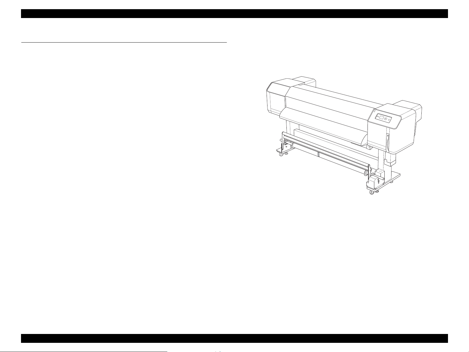
1.1 Features
Epson Stylus Pro GS6000 is a wide-format color Eco-Solvent ink jet printer that
supports 64-inch roll paper. The features of this printer are;
High-speed output
The new type print head achieves high-speed output. It is compatible with paper
up to 1,625 mm in width.
Wide variety of compatible paper
The head is adjustable to two levels of height and compatible with paper up to
1.3 mm in thickness.
Vibrant color reproduction
Eight colors of ink are used for printing in order to reproduce sharp and vivid
colors. This printer uses 950 ml large-capacity ink cartridges. Use of variable dots
can improve color reproduction.
Multi-heater
Heaters are installed at three locations (pre, platen, after) allowing solvent ink to
fix better on paper and dry quickly.
Auto Take-Up Reel Unit
Active indicator
The Active indicator flashes when an error has occurred during operation. Since
the indicator is big, customers can easily check the operational status of the printer
at a distance.
Figure 1-1. External View
This automatically takes up printed paper, keeping it clean and free of creases. It is
also convenient for storage and transportation.
Large-capacity (950 ml) ink cartridge
Epson provides the large-capacity (950 ml) ink cartridges for this printer that
realize the high productivity required for professional work.
High speed USB 2.0 / Gigabit Ethernet
You can connect to a high-speed network (such as USB 2.0 or Ethernet 100/1000)
and that improves the file transfer speed.
PRODUCT DESCRIPTION Features 12
Confidential
Page 13
Epson Stylus Pro GS6000 Revision F
1.2 Basic Specifications
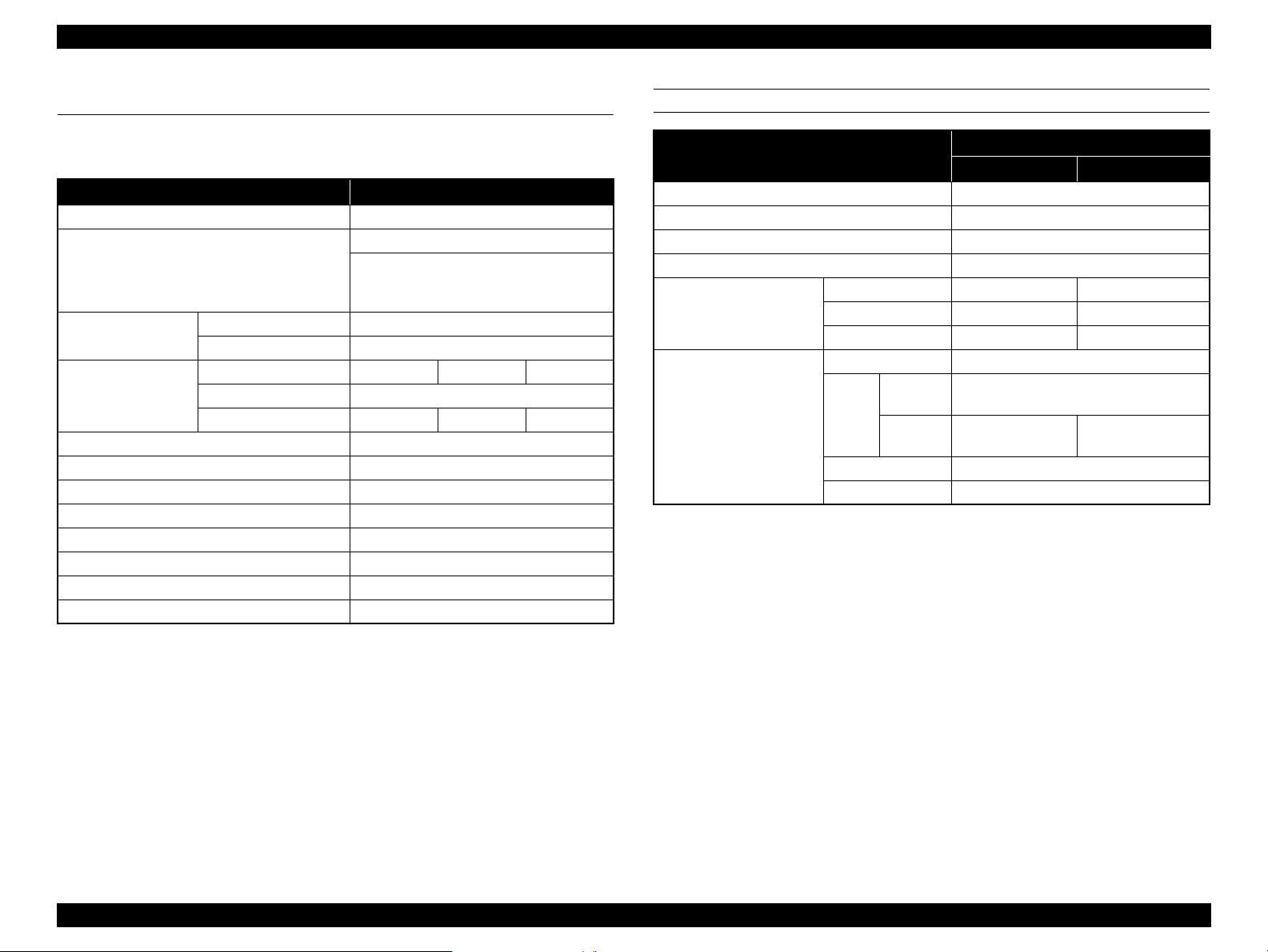
1.2.1 Printer Specifications
Item Specification
Printing method
Nozzle configuration
Character mode
Raster graphic mode
Resolution
Print direction Bidirectional
Control code
Character tables
Character sets EPSON Courier 10 cpi
Paper feed method
Paper path Roll paper
Note *1: Each color has two lines.
Character Pitch 10 cpi
Printing Column 635
Horizontal resolution 540 dpi 720 dpi 1440 dpi
Printable width 1615.0 mm (63.58")
Available dots 34,334 45,779 91,559
RAM 256 MB (MAIN) + 64 MB (Network)
On-demand ink jet
Black: 180 nozzles per color x 2
Color: 180 nozzles per color x 2
(Cyan, Magenta, Light Cyan, Light
Magenta, Yellow, Green, Orange)
Maximum 1440 x 1440 dpi
ESC/P Raster, ESC/P2
PC 437 (US, Standard Europe)
Friction
*1
*1
ELECTRIC SPECIFICATIONS
Item
Rated voltage
Input voltage range AC 90 to 264 V
Rated frequency range
Input frequency range 49 to 61 Hz
Rated current
Power consumption
(MAIN + HEATER)
HEATER 11 A 6 A
TAKE-UP REEL
Ready
mode
Sleep mode Approx. 24 W
Power off: Approx. 3 W
Specification
100-120V Model 220-240V Model
AC 100 to 240 V
50 to 60 Hz
MAIN
Printing Approx. 680 W
Idle heat
ON
Idle heat
OFF
11 A 6 A
0.4A 0.4 A
Approx. 680 W
Approx 48 W Approx 40 W
PRODUCT DESCRIPTION Basic Specifications 13
Confidential
Page 14
EPSON Stylus Pro GS6000 Revision F
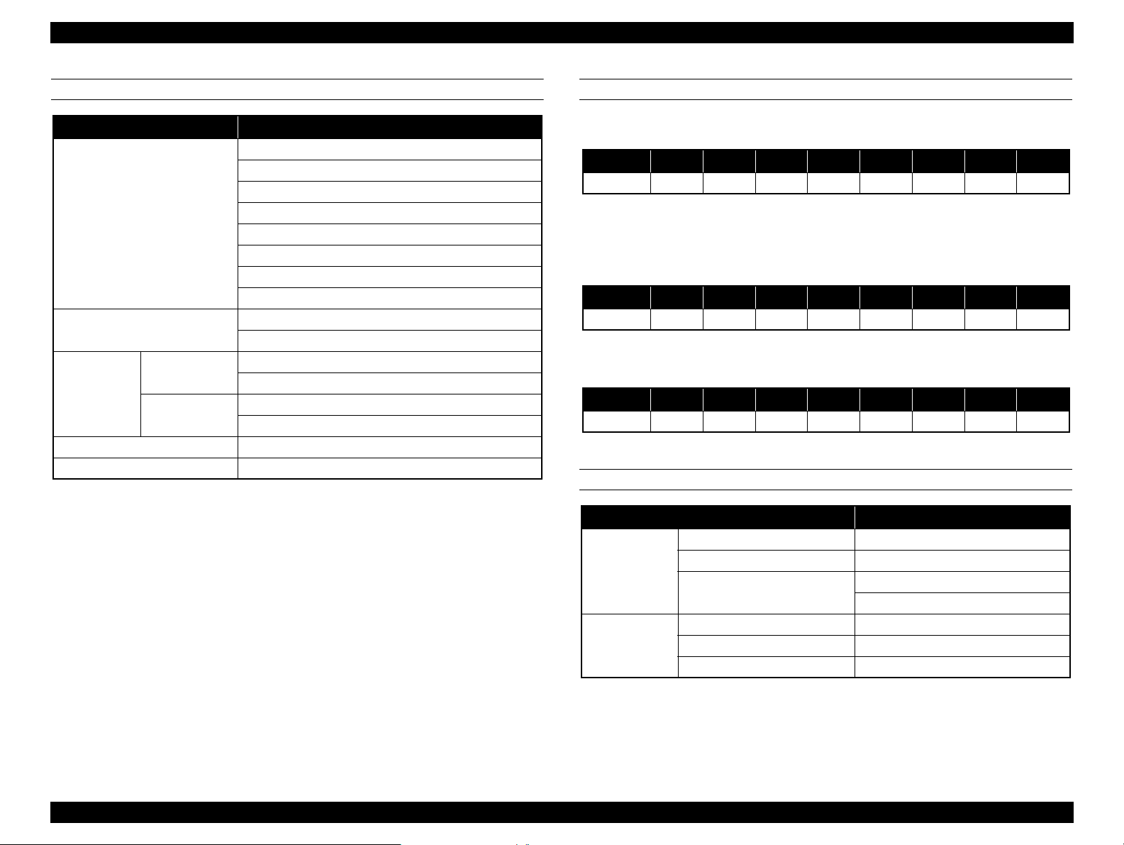
INK CARTRIDGES INK SET CONFIGURATION
Cartridge life
Temperature
Dimensions 53.1 mm (W) x 316.1 mm (D) x 146.2 mm (H)
Item Specification
Cyan
Magenta
Yellow
Colors
Capacity
Storage
(uninstalled)
Storage
(installed)
See expiry date on package or cartridge.
Within 6 months after opening package.
-20 to 40°C (-4 to 104°F)
1 month at 40°C (104°F)
-10 to 40°C (14 to 104°F)
Black
Light Cyan
Light Magenta
Green
Orange
4 days at 32°C (90°F)
950 ml
Ink Set Configuration
Ink Type 1-row 2-row 3-row 4-row 5-row 6-row 7-row 8-row
Pigment Or Gr Lm Lc K Y M C
Note : 1-row starting from the left facing the front of the printer.
Nozzle Configuration
LEFT HEAD:
Ink Type 1-row 2-row 3-row 4-row 5-row 6-row 7-row 8-row
PigmentMMCCKKYY
Note : 1-row starting from the left facing the front of the printer.
RIGHT HEAD:
Ink Type 1-row 2-row 3-row 4-row 5-row 6-row 7-row 8-row
PigmentOrOrGrGrLcLcLmLm
Note : 1-row starting from the left facing the front of the printer.
ENVIRONMENTAL CONDITIONS
Item Specification
Operation 20 to 32°C (68 to 89.6°F)
Temperature
Humidity
Note *: Without condensation
Print Quality Guarantee 22 to 32°C (72 to 89.6°F)
Storage
Operation 40 to 60% RH*
Print Quality Guarantee 40 to 60% RH*
Storage 20 to 80% RH*
-10 to 40°C (14 to 104°F)
4 days at 32°C (90°F)
PRODUCT DESCRIPTION Basic Specifications 14
Confidential
Page 15
EPSON Stylus Pro GS6000 Revision F
ROLL PAPER
Item Specification
Paper size (width)
Internal diameter 3 inches
Outer diameter
When Head height
Thickness
adjustment lever is Low
When Head height
adjustment lever is High
Weight Max. 30 kg
STANDARDS AND APPROVALS
Item Specification
Safety
EMC
Low Voltage Directive
300 mm (12") to 1625 mm (64")
Max. 170 mm (6.7")
Max 0.3 mm
Max 1.3 mm
UL 60950-1
CSA No. 60950-1
2006/95/EC
FCC part 15 subpart B class A
CAN/CSA-CEI/IEC CISPR 22 Class A
AS/NZS CISPR 22 Class A
EN 55022 Class A
EMC Directive
2004/108/EC
EN 60950-1
EN 55024
EN 61000-3-2
EN 61000-3-3
MECHANISM
CR and PF drive method
Paper feed method Loads paper at the rear and ejects paper to the front
Print Head
Ink
Waste ink tank
Take-Up Reel
Unit
Item Specification
Servo motor and DC motor are operated by the firmware
180 nozzles x 8 rows
Two Print Heads are mounted.
Ink supply
method
Ink type Eco-Solvent ink
Ink colors
Attachment Secured to the main unit
Capacity 2,000 ml
Full tank
detection
Noise 50dB or lower
Drive method Driven by DC geared motor
Ink is supplied from the independent ink cartridges
through a tubes via the sub tanks.
Black, Cyan, Magenta, Yellow, Light Cyan,
Light Magenta, Green, Orange
Detected by the float sensor
PRODUCT DESCRIPTION Basic Specifications 15
Confidential
Page 16
EPSON Stylus Pro GS6000 Revision F
300mm
1625mm
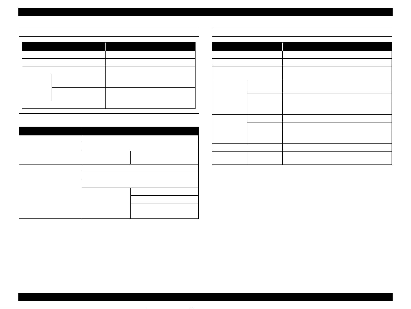
1.2.2 Durability
The following lists the parts that need periodical replacement as indicated.
Item Durability Panel message display
Head Caps
Wiper 1 year None
Head & Dumpers
CR Motor 6,220,000 passes Indicated
PF Motor
6,000,000,000 dots/nozzle None
1 year None
30,000 m. None
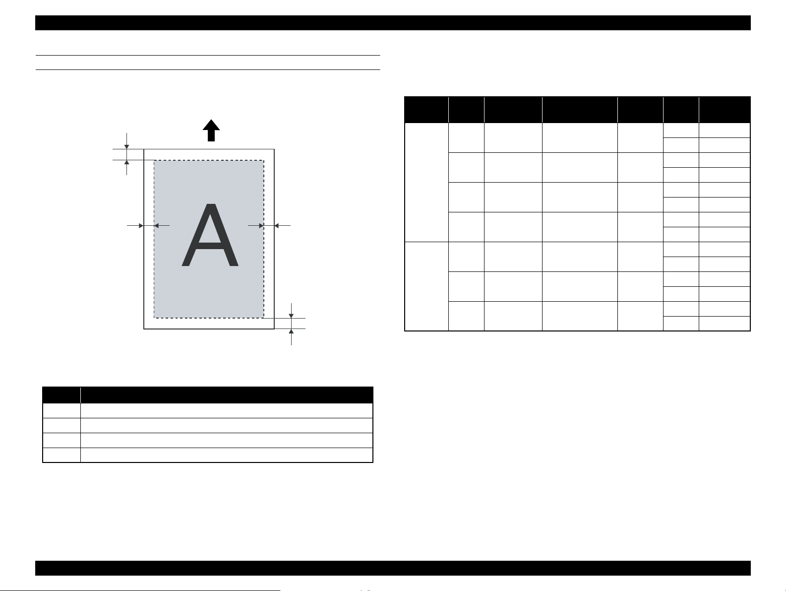
1.2.3 Paper size/Printable area
SUPPORTED PAPER SIZE/THICKNESS
The supported paper size and thickness are described below.
Item Value
Width
Thickness
When Head height adjustment lever is Low Max 0.3 mm
When Head height adjustment lever is High Max 1.3 mm
300 to 1625 mm
Figure 1-2. Supported Paper Size
PRODUCT DESCRIPTION Basic Specifications 16
Confidential
Page 17
EPSON Stylus Pro GS6000 Revision F
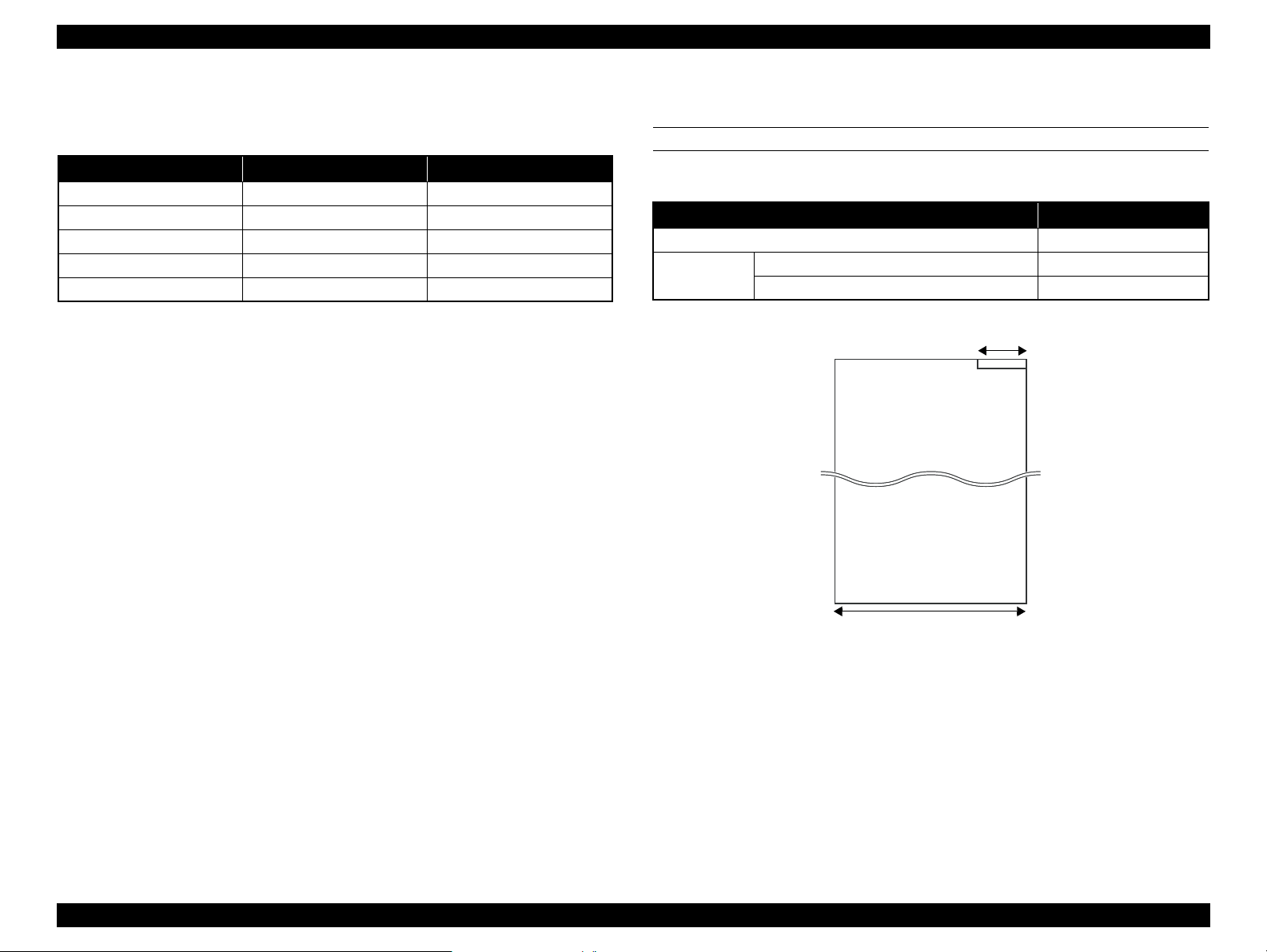
Unit: mm
C
B-R
B-L
A
Feed direction
PRINTABLE AREA
The printable area of this printer is described below.
1.2.4 Print Mode / Print Resolution
The table below lists the print mode and the resolution.
Media
Type
Marking
Film
Banner
Print
quality
Max
Quality
Quality
Quality
Quality
Speed 1 540x720dpi VSD1d-V(400cps) 3x2 pass
Speed 2 720x720dpi VSD1d-V(400cps) 2x2 pass
Speed 3 720x360dpi VSD1d-L(400cps) 2x1 pass
Print density
(HxV)
1440x1440dpi VSD3d-S(320cps) 4x4 pass
1440x720dpi VSD3d-V(320cps) 4x2 pass
1
720x720dpi VSD3d-V(400cps) 4x2 pass
2
540x720dpi VSD3d-V(400cps) 3x2 pass
3
Dot size
Pass
(CRxPF)
Uni/Bi
Uni-D 1.6
Uni-D 3.3
Uni-D 3.6
Uni-D 5.5
Uni-D 5.5
Uni-D 8.3
Uni-D 16.6
Throughput
2
(m
Bi-D 2.9
Bi-D 5.8
Bi-D 7.0
Bi-D 9.3
Bi-D 9.3
Bi-D 13.6
Bi-D 25.3
/h)
Item Value
A Min. 5 mm
B-L
B-R 5 to 25 mm
C
Min. 5 mm When end of the roll paper, the margin will be 77.4 mm.
Figure 1-3. Printable Area
5 to 25 mm
PRODUCT DESCRIPTION Basic Specifications 17
Confidential
Page 18
EPSON Stylus Pro GS6000 Revision F
1,045 mm
2,698 mm
1,267 mm
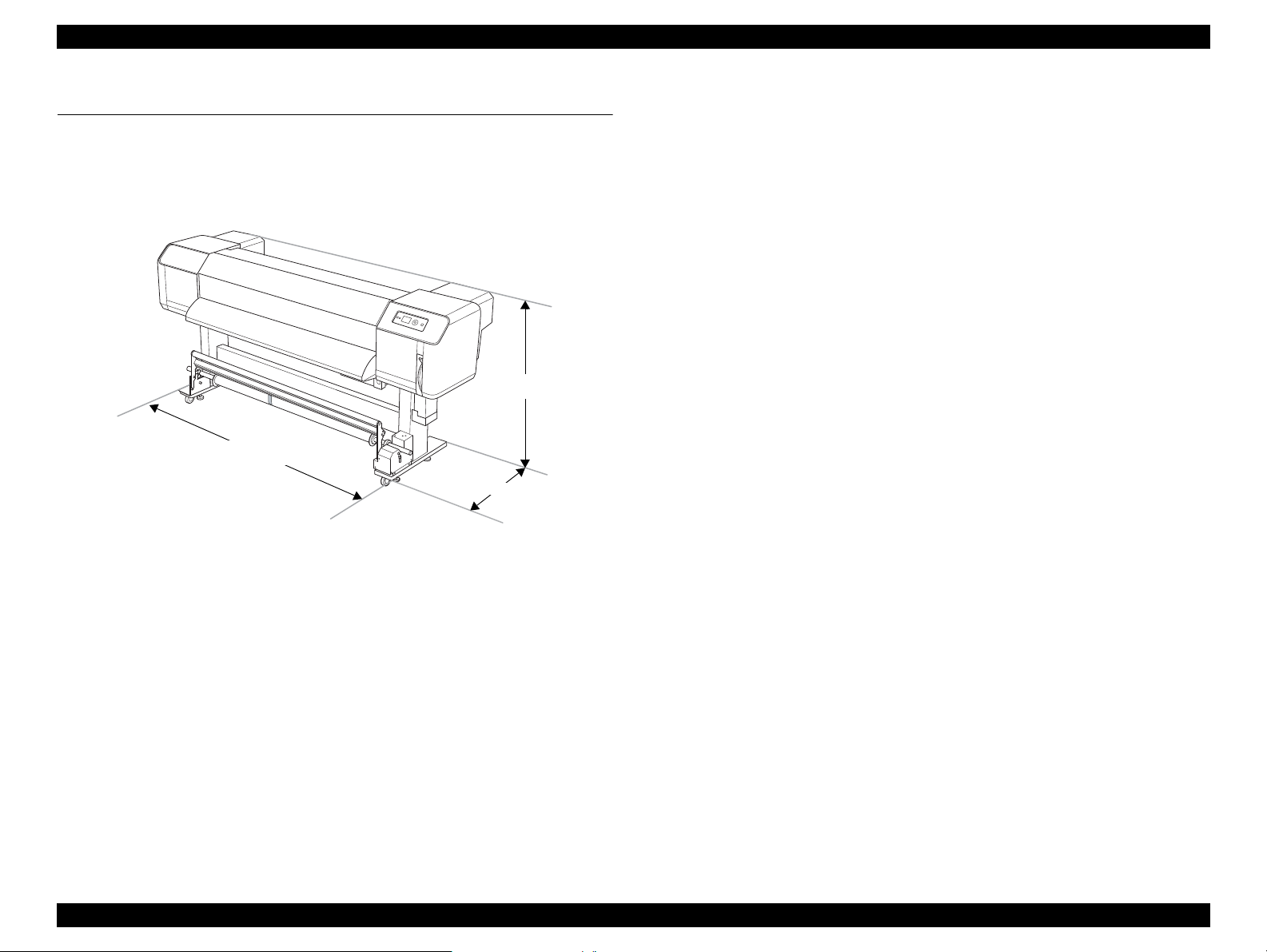
1.3 Dimensions and Main Components
This section describes the printer dimensions and the main components.
1.3.1 Dimensions and Weight
Figure 1-4. Printer Dimensions (standard)
Dimensions
Standard (wi th the Auto Take-up Reel Unit):
2,698 (W) x 1,045 (D) x 1,267 (H) mm
Without the Auto Take-up Reel Unit:
2,698 (W) x 943 (D) x 1,267 (H) mm
Weight
Printer main body and the Stand (excludes the ink cartridges and paper):
Approx. 183 kg
Printer main body only (excludes the ink cartridges and paper):
Approx. 150 kg
Auto Take-up Reel unit: Approx. 19 kg
PRODUCT DESCRIPTION Dimensions and Main Components 18
Confidential
Page 19
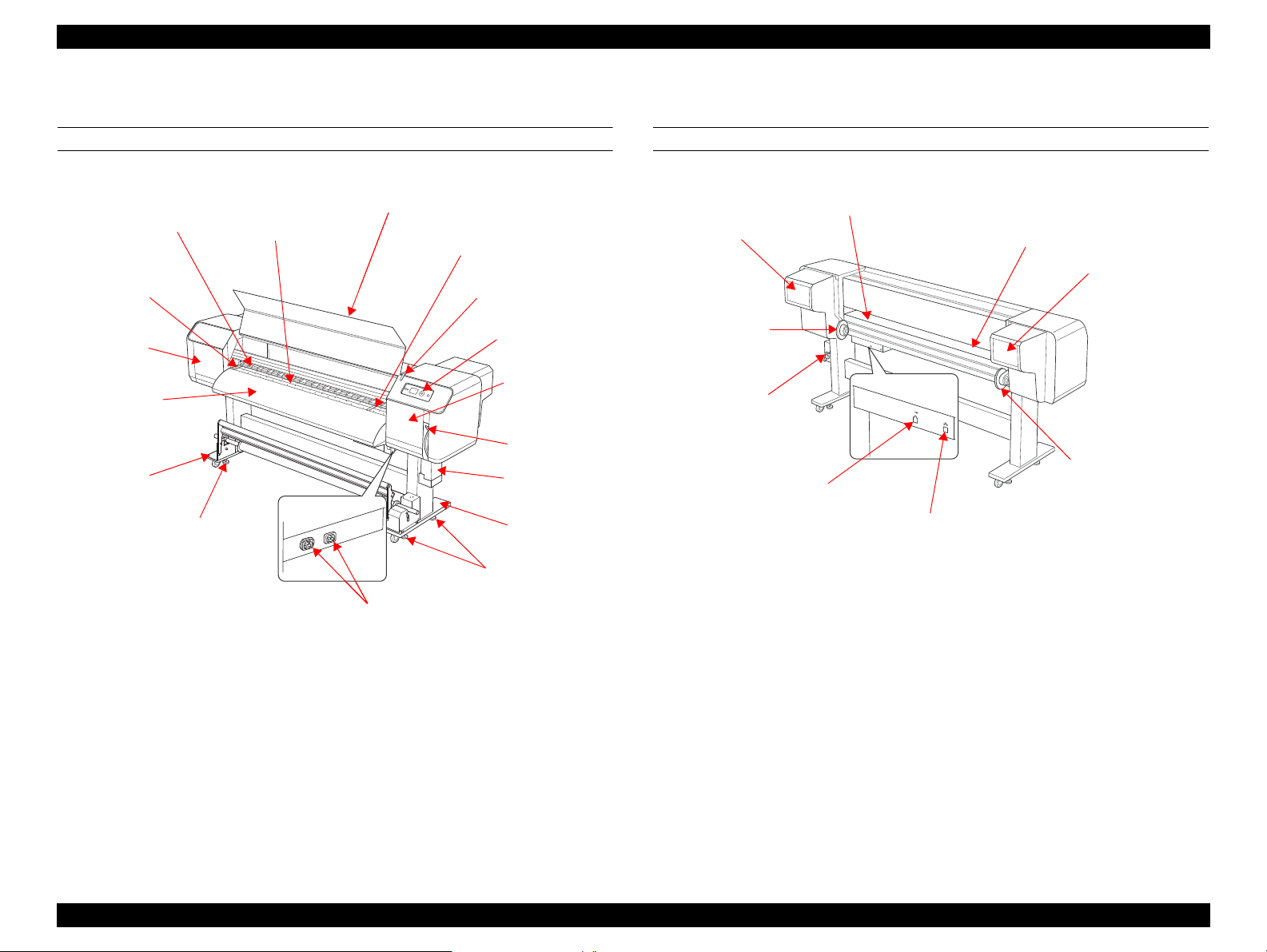
Epson Stylus Pro GS6000 Revision F
Pressure Rollers
Front Cover
Platen
Paper holder plate
Maintenance
Cover
Paper Guide
Front Cover
Paper Holder Plate
Active Indicator
Stand
Adjuster
AC inlet
Adjuster
Stand
Ink drain tank
Paper lever
Maintenance
Cover
Control panel
Paper Guide
Paper Feed Slot
Ink Cartridge
Compartment
Roll Paper Holders
Network Interface Connector
USB Interface Connector
Waste Ink Valve
Roll Paper Holders
Ink Cartridge
Compartment
1.3.2 Part Names
FRONT
Figure 1-5. Part Name (Front)
REAR
Figure 1-6. Part Name (Rear)
PRODUCT DESCRIPTION Dimensions and Main Components 19
Confidential
Page 20
EPSON Stylus Pro GS6000 Revision F
[Pause/Reset]
button
b
a
[Heater]
button
c
[Enter]
button
d
[Low Heat]
button
g
[High Heat]
button
h
[Power] button
[Paper Feed]
button
e
[Paper Feed]
button
e
[Menu]
button
f
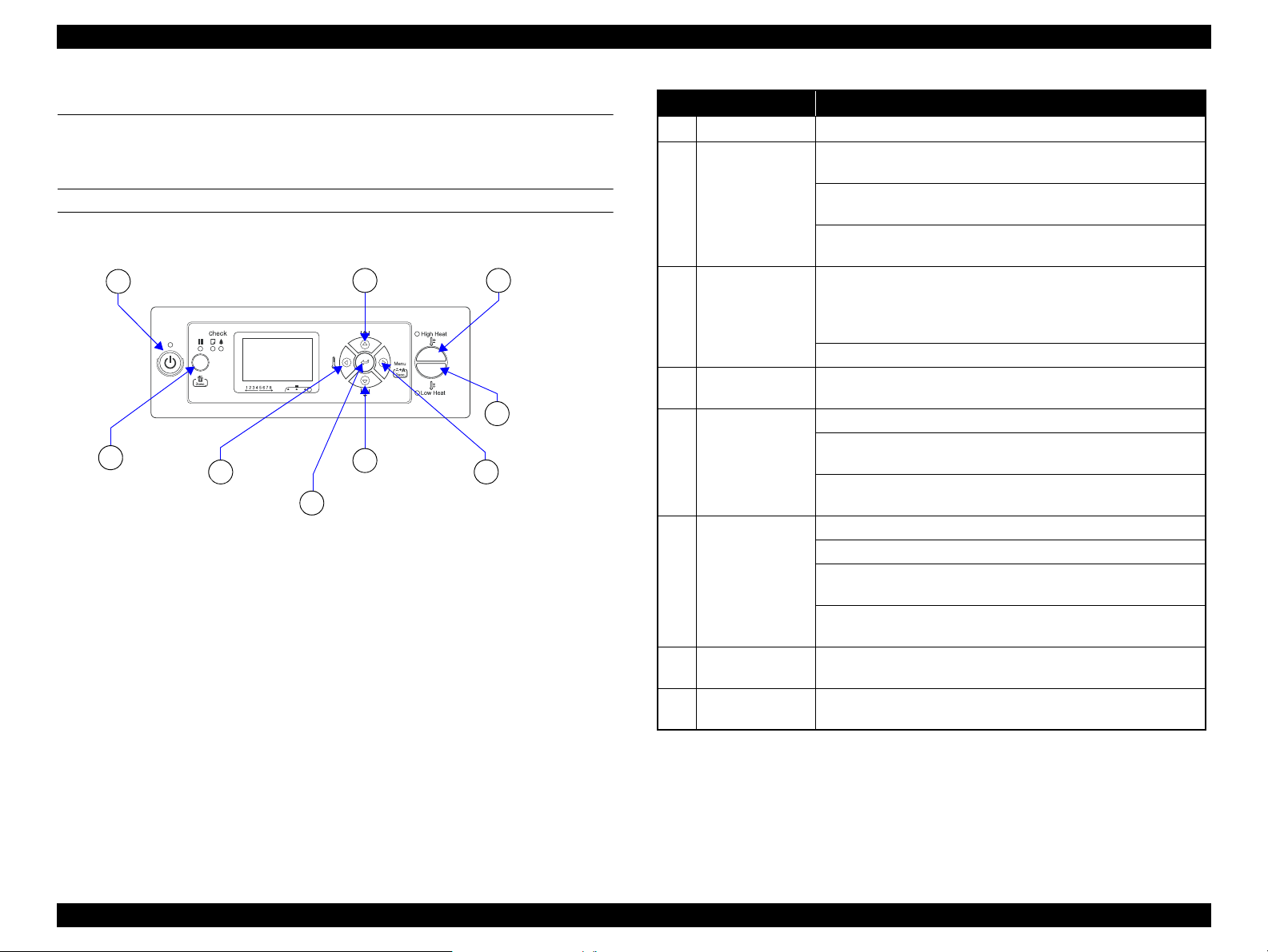
1.4 Control Panel
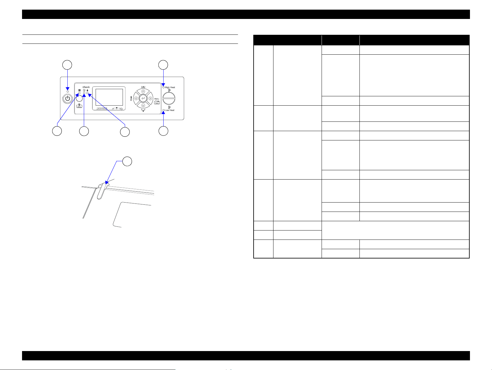
1.4.1 Buttons and Indicators
BUTTONS
Figure 1-7. Buttons
Button Name Function
a
b
c
d[Enter]
e [Paper Feed]
f [Menu]
g [Low Heat]
h [High Heat]
Note *1 : When AUTO TAKE-UP REEL is ON in the Menu mode, the roll paper cannot be
[Power]
[Pause/Reset]
[Heater]
fed in the reverse direction.
Turns the printer on or off.
Stops printing temporarily, or restarts printing if pressed when the
printer is in the pause mode.
Clears print data in the printer memory if pressed and held for
3 seconds.
The printer returns to the READY state when this button is
pressed in the Menu mode.
Selects a heater type. From the right, Pre Heater, Platen Heater,
and After Heater are displayed on the LCD panel. Select a heater
type, and then press the [High Heat] button or [Low Heat] button
to change the preset temperature.
Returns to the previous level when pressed in the Menu mode.
Sets the selected parameter in the selected item in the Menu mode.
Executes the item if the selected item is for execution only.
Feeds the roll paper in the forward or reverse direction.
Changes the parameter in the forward or reverse order when
selecting a desired parameter in the Menu mode.
The numeric value is decreased or increased during numerical
input.
Enters the Menu mode when pressed in the READY state.
Enters the Printer Status menu if pressed during printing.
Stops printing temporarily, or restarts When pressed in the Menu
mode, a desired menu can be selected.
Performs Cleaning (Light) to clean the print heads if pressed and
held for 3 seconds.
Decreases the preset temperature of the heater. You can also
change the preset temperature while printing.
Increases the preset temperature of the heater. You can also
change the preset temperature while printing.
*1
PRODUCT DESCRIPTION Control Panel 20
Confidential
Page 21
EPSON Stylus Pro GS6000 Revision F
Ink Check
light
Pause
light
b
Paper Check
light
c
d
Active indicator
g
Low Heat
light
e
Power light
a
High Heat light
f
LIGHTS (LED)
Figure 1-8. Lights (LED)
Name Status Description
Power light
a
b Pause light
c Paper Check light
d Ink Check light
e Low Heat light
f High Heat light
g Active indicator
On The printer is on.
The printer is:
• analyzing the data
Flashing
Off The printer is off.
On
Off The printer is ready to print data.
On No paper is loaded in the printer.
Flashing
Off The printer is ready to print data.
On
Flashing The installed ink cartridge is nearly expended.
Off The printer is ready to print data.
The status or the meaning is shown by combination of the light.
See ?<Combination of Low and High Heat Lights>? (p22).
Flashing An error has occurred.
Off The printer has no error.
• printing
• cleaning
• in process of turning off
The printer is in the Menu mode.
The printer is in the pause mode.
Paper is jammed.
Paper is not loaded straight.
Paper is nearly ended.
The maintenance call has occurred.
The installed ink cartridge is expended.
The ink cartridge is not installed.
The wrong ink cartridge is installed.
PRODUCT DESCRIPTION Control Panel 21
Confidential
Page 22
EPSON Stylus Pro GS6000 Revision F
a
b
c
d
e
<Combination of Low and High Heat Lights>
When the printer is READY
High Heat Low Heat Status
On On The three heaters have reached preset temperature.
Flashing Off
Flashing Flashing A heater error has occurred.
Off Off Heaters are off.
One or more of the heaters is/are trying to reach the preset
temperature.
When selecting a Heater to set the temperature.
High Heat Low Heat Status
On On
On Off
Off On
You can change the temperature to higher or lower than
the current setting.
You can change the temperature to higher than the current
setting.
You can change the temperature to lower than the current
setting.
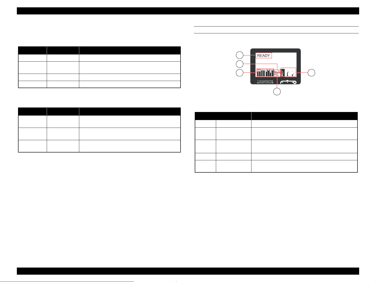
DISPLAY
Figure 1-9. Display
Name Description
a
b
c
d Platen Gap icon Displays the Platen Gap setting that is read by the sensor.
eHeater icon
Messages
Paper Type
Ink cartridge
status icon
Displays the printer status, operation, and error messages.
When you select paper type (1 to 30) in the Paper Setup
menu, the number you selected appears.
Displays the remaining amount of ink in each cartridge.
Displays the preset temperature and the current temperature
of the Pre Heater, Platen Heater, and After Heater.
PRODUCT DESCRIPTION Control Panel 22
Confidential
Page 23
EPSON Stylus Pro GS6000 Revision F
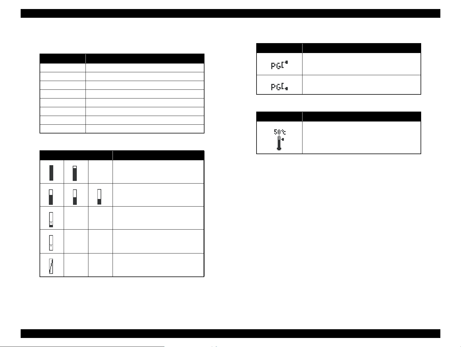
Ink cartridge status icon
Ink cartridges
No. Ink color
1 Orange (OR)
2 Green (GR)
3 Light Magenta (LM)
4 Light Cyan (LC)
5Black (BK)
6 Yellow (Y)
7Magenta (M)
8 Cyan (C)
Ink remaining
Icon Description
Platen Gap icon
Icon Explanation
High
Low
Heater icon
Icon Explanation
The preset temperature is indicated by the graduation
and the numerical value.
The current temperature is indicated by the
thermometer icon.
There is enough ink remaining.
We recommend you prepare a new ink
cartridge.
The icon flashes. The yellow ink cartridge
is nearly empty. Prepare a new ink
cartridge.
The ink is expended so you cannot print.
Replace the ink cartridge with a new one.
This icon indicates the yellow tank.
Cartridge error or no cartridge.
PRODUCT DESCRIPTION Control Panel 23
Confidential
Page 24
EPSON Stylus Pro GS6000 Revision F
1.4.2 Panel Settings
This section describes the panel settings that customers can change.
For the map of menu, see ?7.2 Panel Menu Map? (p259)
MENU LIST
.
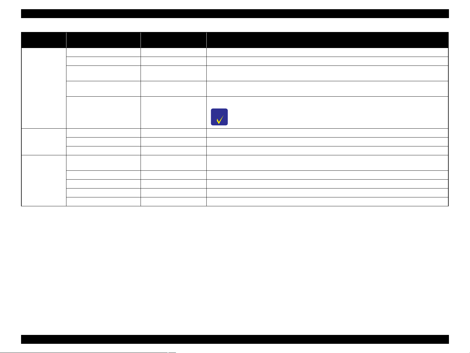
Menu Item
SIDE MARGIN
PAPER SIZE CHECK
PAPER SKEW CHECK
PRINTER SETUP
PRINT NOZZLE PATTERN
HEATING TIME
FLUSH ONTO PAPER
FLUSING FREQUENCY
PAPER ORIGIN SETUP 0mm* - 800mm You can set the beginning of printing (origin) of the horizontal direction.
Parameter
(*: Default setting)
5mm* - 25mm
(0.2inch* - 1.00inch)
ON* You can select whether to check the paper width.
OFF
ON* If the paper is not straight, “PAPER SKEW” appears on the LCD panel and the printer stops printing.
OFF
OFF*
ON: EVERY PAGE
ON: EVERY 10 PAGES
OFF
10min* - 240min
YES* You can set up the flushing operation while printing.
NO
5PASS* You can set the frequency that the print head returns to the flushing box when setting YES in the FLUSH ONTO
1PASS - 999PASS
You can set the margin for left and right side.
ON:
Check the paper width and top edge of the paper.
NO:
Do not check the paper width and top edge of the paper. The printer continues to print even if the paper width
does not match the data width, and the printer may print beyond the paper. Because this soils the inside of the
printer, we recommend you select ON. This may result in a wider blank margin at the top of each page.
A paper align error does not occur even if the printed data is out of range of the paper, and the printer continues
to print.
When you select ON, the printer prints the nozzle check pattern before printing each print job or the 10th sheet,
depending on the setting you have set.
You can set the length of time to preheat the heaters. When more than the set time has passed after turning on
the printer or after printing is finished, each heater turns off.
YES:
The printer performs the flushing operation on the page margins. The printing speed improves since the
number of times to return to the flushing box is decreased.
NO:
Performs the flushing operation to return to the flushing box every time the print head goes and returns.
PAPER setting. (When you select 5PASS, the print head returns to the flushing box every time the print head
goes and returns five times.)
Explanation
PRODUCT DESCRIPTION Control Panel 24
Confidential
Page 25
EPSON Stylus Pro GS6000 Revision F
C A U T I O N
C H E C K
P O I N T
Menu Item
AUTO TAKE-UP REEL
HEAD FAN (COOLING FAN)
PRINTER SETUP
REGULAR CLEANING
ROLL PAPER COUNTER
INITIALIZE SETTINGS EXECUTE You can return all setting values you have made in the Printer Setup menu to their factory set value.
PAPER TYPE
PAPER SETUP
PAPER SETUP
Parameter
(*: Default setting)
Explanation
ON* Use this setting when using the Auto Take-Up Reel Unit. When ON is selected, you cannot feed the roll paper in
the reverse direction.
OFF
When the Auto Take-Up Reel Unit is not installed, do not set to ON. By doing so, the product will be
unable to function properly.
ON*
OFF
You can set up the head fan operation. If print blurring or dot losses occur, select ON.
OFF Yo u can set the auto cleaning interval of this printer. When more than the set time ha s passed since t he previ ous
print job, the print head is cleaned automatically to prevent it from clogging.
The timer will be reset at the following timing:
1h, 2h, 3h, 4h, 5h, 6h*,
9h, 12h, 18h, 24h
when turning on the printer
when changing the interval of the auto cleaning
when performing the cleaning manually
OFF* In this setting, the alert can be set off when the remaining paper falls below 2m. Enter the remaining amount
5 - 99.5m (15 - 300ft)
STANDARD*
PAPER No.1 - 30
(length) of paper currently set on the printer. This menu is displayed only when the REMAINING PPR SETUP
in Maintenance Mode is set to ON.
You can select the paper type to print.
STANDARD* When you select STANDARD, the default settings are used.
When you select a number (between 1 to 30), you can register the settings (such as Print Mode, Paper Feed
Adjust, Head Alignment, Pre Heater, Platen Heater, After Heate r, M/W Adjus tme nt, Paper Suction, Drying
PAPER No.1 - 30
Time, Carriage Movement, Print Multiple Layer) or to recall these settings you have made. The number you
select here is displayed on the LCD panel.
See ?Details of PAPER SETUP? (p29).
PRODUCT DESCRIPTION Control Panel 25
Confidential
Page 26
EPSON Stylus Pro GS6000 Revision F
C H E C K
P O I N T
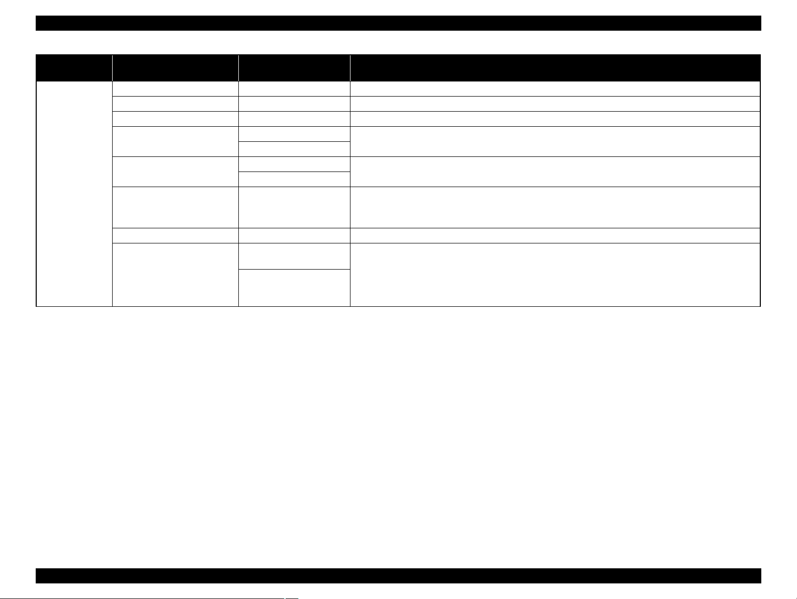
Menu Item
CLEANING (VERY LIGHT) EXECUTE You can perform very light cleaning. It discharges a smaller amount of ink compared to CLEANING (LIGHT).
CLEANING (LIGHT) EXECUTE You can perform normal cleaning. Select this mode normally.
CLEANING (MEDIUM) EXECUTE
MAINTENANCE
CLEANING (HEAVY) EXECUTE
HEAD WASHING EXECUTE
CARRIAGE MAINTENANCE EXECUTE The carriage will move into a position allowing you to clean the cleaning wiper and around the print head.
MAINTENANCE
CLOCK SETTING MM/DD/YY HH:MM You can set year, month, date, hour, and minute.
CONTRAST ADJUSTMENT -20 - 0 - +20 You can adjust the contrast of the LCD panel.
NOZZLE CHECK PRINT
STATUS SHEET PRINT You can print the current printer status.
TEST PRINT
NETWORK STATUS SHEET PRINT You can print the current network status.
JOB INFORMATION PRINT You can print the job information saved in the printer (up to 10 jobs).
CUSTOM PAPER PRINT You can print custom paper information registered in the Paper Setup menu.
Parameter
(*: Default setting)
Explanation
You can perform strong cleaning. It discharges a larger amount of ink compared to CLEANING (LIGHT). Use
this mode when the print head clog situation does not improve by CLEANING (LIGHT).
You can perform stronger cleaning. It discharges a larger amount of ink compared to CLEANING (MEDIUM).
Use this mode when the print head clog situation does not improve by CLEANING (MEDIUM).
You can perform the head washing.
Cleaning cartridge (option) is needed to perform head washing.
You can print a print head nozzle check pattern for each ink cartridge. It also prints the firmware version and the
ink usage.
PRODUCT DESCRIPTION Control Panel 26
Confidential
Page 27
Epson Stylus Pro GS6000 Revision F
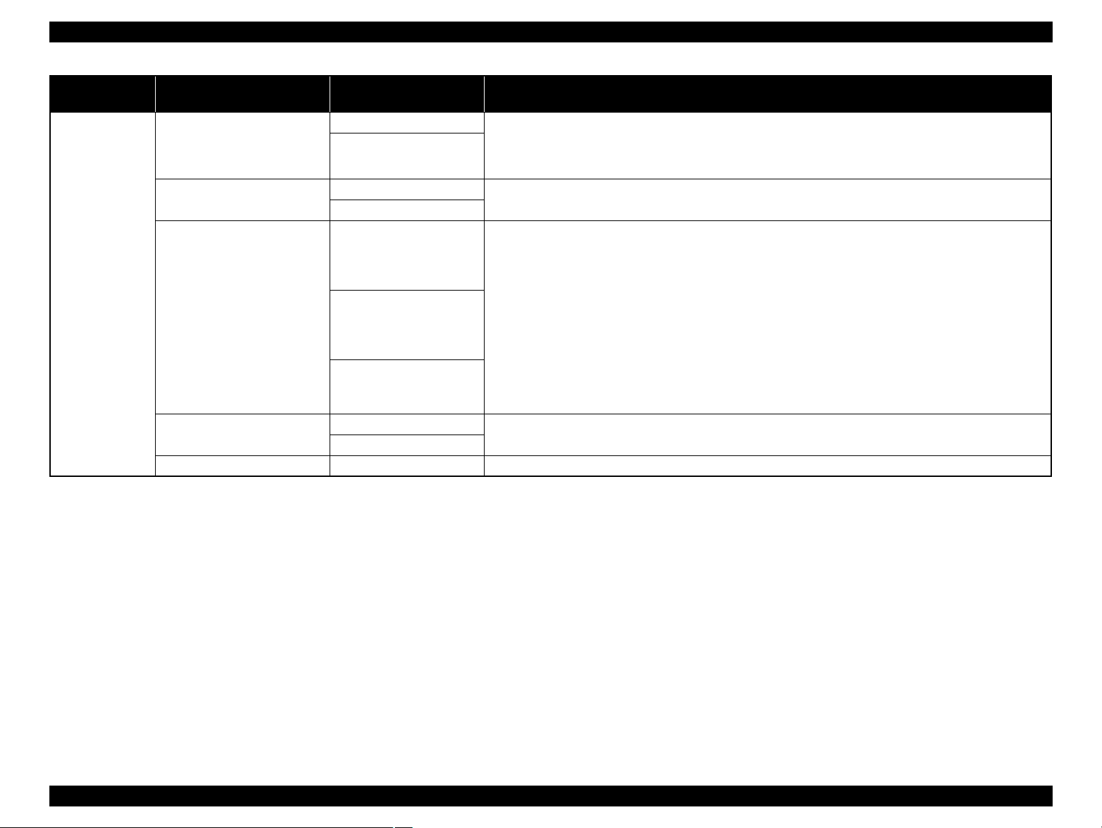
Menu Item
VERSION T0xxxx-xx xx IBCC You can see the firmware version.
PRINTABLE PAGES (ink color) nnnnnn PAGES Yo u can see the number of pages printable for each ink cartridge.
INK LEVEL (ink color) nn% You can see the status of each ink cartridge.
USAGE COUNT
CLEAR USAGE COUNT
PRINTER
STATUS
JOB HISTORY
TOTAL PRINTS nnnnnn PAGES You can see the total amount of pages you have printed.
EDM STATUS
Parameter
(*: Default setting)
INK xxxxx.xml
PAPER xxxxx.xcm
INK EXECUTE
PAPER EXECUTE
No. 0-No. 9
INK xxxxx.xml
PAPER xxx.x cm2
NOT STARTED,
ENABLED, DISABLED
LAST UPLOADED
MM/DD/YY HH:MM GMT,
(NOT UPLOADED)
Explanation
You can see the ink consumption in milliliters and paper consumption amount in centimeters. Values shown in
USAGE COUNT are rough indications.
You can clear the values set in USAGE COUNT.
You can see ink consumption (INK) in milliliters and paper size (PAPER) for e ach print job saved in t he printer.
The latest job is saved as No. 0.
You can see if the EDM is enabled or disabled. If the EDM is enabled, the time that the EDM status was last
uploaded is displayed.
PRODUCT DESCRIPTION Control Panel 27
Confidential
Page 28
Epson Stylus Pro GS6000 Revision F
Menu Item
NETWORK SETUP
IP ADDRESS SETTING
NETWORK
SETUP
IP, SM, DG SETTING
BONJOUR
INIT NETWORK SETTING EXECUTE You can return the network settings of the printer to the factory default value.
Parameter
(*: Default setting)
DISABLE You can configure the network setting of the printer. The following items appear only when ENABLE is
selected. After setting the items, press the button in the Network Setup menu, so the network is reset and the
ENABLE
AUTO
PANEL
IP ADDRESS
000.000.000.000 -
192.168.192.168* -
255.255.255.255
SUBNET MASK
000.000.000.000 -
255.255.255.000* -
255.255.255.255
DEFAULT GATEWAY
000.000.000.000 -
255.255.255.255*
ON
OFF
network connection is available after 15 seconds. The Network Setup menu does not appear while resetting the
network.
You can select the method to set the IP address to the printer. When you select PANEL, IP, SM, DG SETTING
appears.
You can change settings of IP address, subnet mask, and default gateway.
You can enable or disable the Bonjour setting.
Explanation
PRODUCT DESCRIPTION Control Panel 28
Confidential
Page 29
Epson Stylus Pro GS6000 Revision F
a
b
c
C H E C K
P O I N T
Details of PAPER SETUP
After you have selected the paper number, make the following settings.
Item Parameter Explanation
MAX QUALITY You can select the print quality (print mode) according to the usage of print data or print speed.
QUALITY1
QUALITY2
QUALITY3
PRINT MODE
SPEED1
SPEED2
SPEED3
PAPER FEED ADJUST
LINE FEED ADJUST
PRINT SAMPLE PATTERN
HEAD ALIGNMENT BI-D ALL You can perform print head alignment. Check the pattern and enter the value that has the smallest gaps.
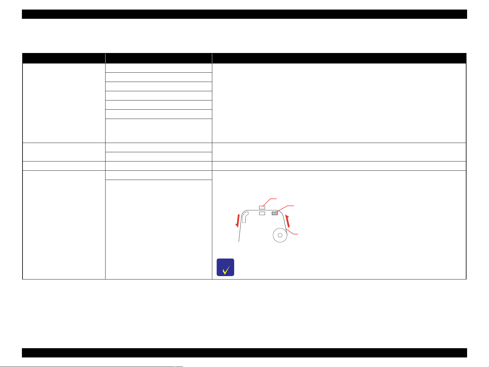
OFF You can set the Pre Heater temperature. The Pre Heater is located under the rear paper guide. Set up to preheat
MAX QUALITY, QUALITY1, QUALITY2:
Performs high-quality printing. Use this mode when printing high quality graphic data that includes photo
data. MAX QUALITY provides priority to print quality. QUALITY1 is balanced between quality and
efficiency. QUALITY2 provides priority to print efficiency.
QUALITY3:
Performs standard printing. Use this mode when printing graphic data.
SPEED1, SPEED2, SPEED3:
Performs high-speed printing. Use this mode when printing text or graphics. SPEED1 provides priority to
print quality. SPEED2 is balanced between quality and efficiency. SPEED3 provides priority to print
efficiency.
You can set the paper feed amount of the printable area. If the paper feed value is too large, white horizontal
micro-banding may appear. If the paper feed value is too small, dark horizontal micro-banding may appear.
the paper before printing and insulate the temperature change in the printer section.
PRE HEATER
30oC to 50oC (86oF to 122oF)
a. Print head, b. Pre Heater, c. Roll paper
For appropriate temperatures to set to this function, see the instructions included with the paper, or
contact your supplier.
PRODUCT DESCRIPTION Control Panel 29
Confidential
Page 30
Epson Stylus Pro GS6000 Revision F
a
b
c
C H E C K
P O I N T
a
b
c
C H E C K
P O I N T
Item Parameter Explanation
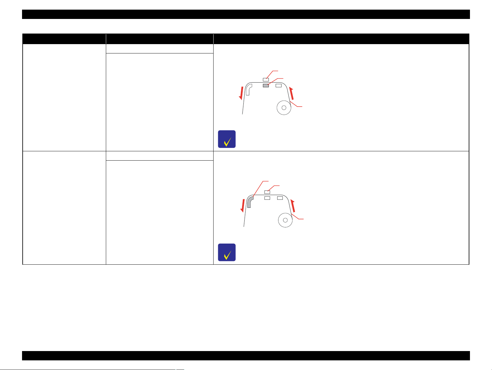
OFF You can set the Platen Heater temperature. The Platen Heater is locate d und er the print heads. Set this menu to
warm up ink and improve print quality.
PLATEN HEATER
AFTER HEATER
30oC to 50oC (86oF to 122oF)
a. Print head, b. Platen Heater, c. Roll paper
For appropriate temperatures to set to this function, see the instructions included with the paper, or
contact your supplier.
OFF You can set the After Heater temperature. The After Heater is located under the front paper guide. Set this menu
to dry printed paper.
30oC to 50oC (86oF to 122oF)
a. After Heater, b. Print head, c. Roll paper
For appropriate temperatures to set to this function, see the instructions included with the paper, or
contact your supplier.
PRODUCT DESCRIPTION Control Panel 30
Confidential
Page 31

Epson Stylus Pro GS6000 Revision F
C A U T I O N
Item Parameter Explanation
LOW A to B You can improve the print quality by adjusting the print mode you have set.
MEDIUM A to D
HIGH A to D
M/W ADJUSTMENT
(Micro Weave Adjustment)
EXTRA HIGH A to B
PAPER SUCTION
HIGH
LOW
DRYING TIME 0.0sec to 10.0sec
LOW A, B:
The effect of M/W Adjustment function will be minimized. If obvious white lines or uneven print density
appear on printed paper in LOW A, set to LOW B.
MEDIUM A, B, C, D:
The printing joint between two head passes will have a wave form. If obvious white lines or uneven print
density appear on printed paper in MEDIUM A, print samples using the other settings and select the best print
result from MEDIUM B to MEDIUM D.
HIGH A, B, C, D:
Perform printing at a slow speed compared with “MEDIUM”. Set up this menu when improving the print
quality compared with “MEDIUM”. If obvious white lines or uneven print density appear on printed paper in
HIGH A, change the setting to the one with the best print result in HIGH B to HIGH D.
EXTRA HIGH A:
Performs “MEDIUM” printing using half of the nozzles of the print head. Since only a half of the nozzles is
used, printing speed becomes half of MEDIUM A to MEDIUM D. Set up this menu when improving the print
quality compared with HIGH A to HIGH D.
EXTRA HIGH B:
Performs “MEDIUM” printing using the other half of the nozzles of the print head that is used for EXTRA
HIGH A. Since only a half of the nozzles is used, printing speed becomes half of MEDIUM A to MEDIUM D.
Set up this menu when improving the print quality compared with HIGH A to HIGH D.
You can set the suction pressure used to feed the printed paper.
You can set the ink drying time for each print head pass. The range is 0 to 10 seconds. Depending on the ink
density, paper type or printing speed, the ink does not dry soon. In this case, set the drying time longer.
When you set the drying time longer, missing dots might occur in the printing.
DATA WIDTH You can set the range that the print head moves while printing.
DATA WIDTH:
The print head moves between the print data width. This improves the print speed since decreasing the
CARRIAGE MOVEMENT
PRINTER FULL WIDTH
transferring range of the print head.
PRINTER FULL WIDTH:
The print head moves from origin to the maximum paper width. This keeps printing quality the same even though
the printing size (width) differs.
PRINT MULTIPLE LAYER
OFF
2 to 8
You can set the overwrite count per line.
PRODUCT DESCRIPTION Control Panel 31
Confidential
Page 32

Epson Stylus Pro GS6000 Revision F
1.4.3 Maintenance Mode
You can change the language or unit used on the display or return all the setting values
to their factory default.
HOW TO ENTER & EXIT
1. Turn off the printer by pressing the [Power] button.
2. Turn the printer on while pressing the
3. To exit the Maintenance mode, press the [Power] button to turn off the printer.
MAINTENANCE MODE LIST
Item Parameter Explanation
ENGLISH
FRENCH
ITALIAN
LANGUAGE
LENGTH UNIT
THERMOMETER UNIT
GERMAN
SPANISH
PORTUGUE
DUTCH
JAPANESE
METRIC
FEET/INCH
o
C
F
[Pause/Reset] button.
You can select the language to be
displayed on the LCD panel.
You can select a unit of measurement
to use to display length.
You can select a thermometer unit.
Item Parameter Explanation
DEFAULT PANEL EXECUTE
CUSTOM 0 - 255 Not available currently.
OFF ROLL PAPER COUNTER menu is
REMAINING PPR SETUP
ON
You can set all setting values you
made in the Menu mode to their
factory set value.
added to the PRINTER SETUP menu
when set to ON.
PRODUCT DESCRIPTION Control Panel 32
Confidential
Page 33

Epson Stylus Pro GS6000 Revision F
C A U T I O N
1.4.4 Serviceman Mode
This printer has the Serviceman Mode which is provided for serviceman to
troubleshoot problems and so on. This section explains how to enter into the
Serviceman mode.
See ?7.2 Panel Menu Map? (p259) for explanation about menus provided in the mode.
Do not disclose the Serviceman Mode to the users.
HOW TO ENTER THE SERVICEMAN MODE
1. Turn off the printer by pressing the [Power] button.
2. Turn the printer on while pressing the
[Menu] buttons.
3. To exit the Serviceman mode, press the [Power] button to turn off the printer.
[Pause/Reset], [Paper Feed ], and
PRODUCT DESCRIPTION Control Panel 33
Confidential
Page 34

Epson Stylus Pro GS6000 Revision F
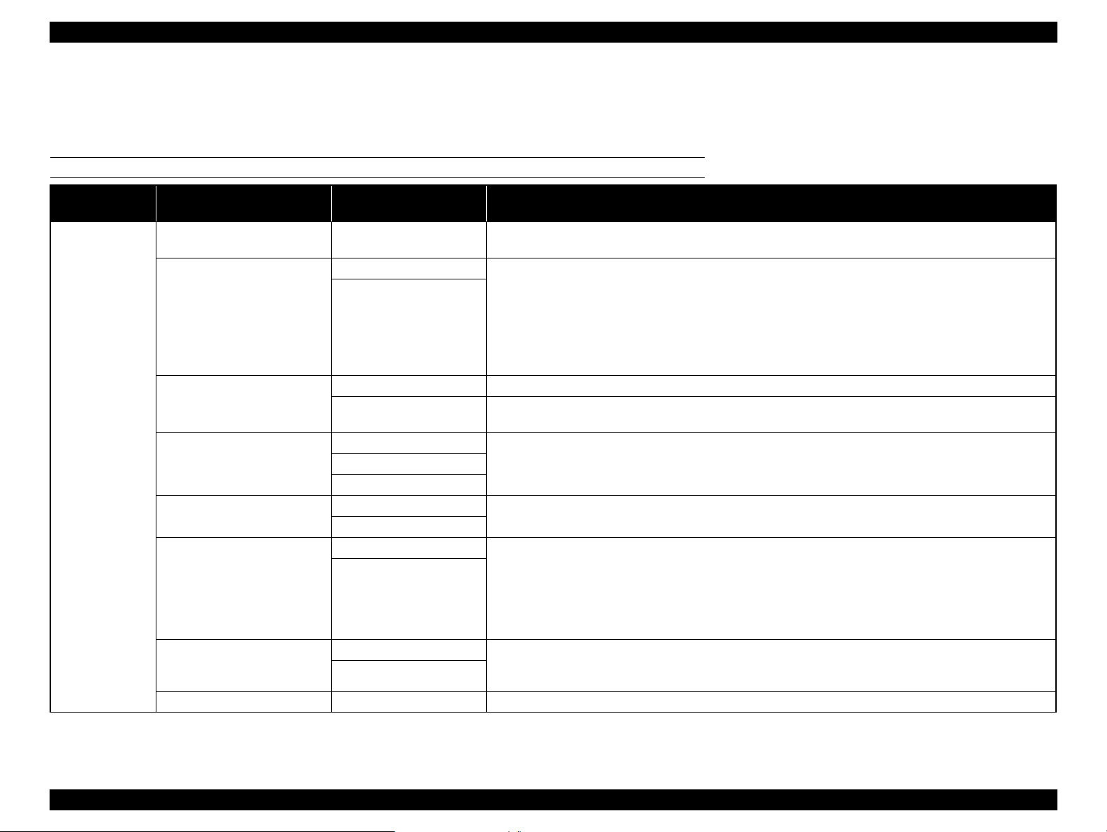
MENU LIST
Table 1-1. Menu List
Menu Explanation
F/W
BOOT
Pram1
Pram2
Serial No.
USB Serial No.
Key
LCD
LED
Printer Check LED
Paper Lever
Mtank
Cartridge Not
Rear AD
Head Temp
Drv Temp
PG
CR Origin
EdgeAD
Paper (All)
Paper (Duty)
Paper1
Paper2
Paper3
Paper4
HT Fan
Head Fan 1
Head Fan2
Displays the F/W version and other parameters.
Checks the operation of the control panel and active indicator.
Checks the sensors operation.
Checks the fans operation.
Test
Version
Panel
Sensor
Encoder CR/PF Checks the encoders operation.
Fan
PRODUCT DESCRIPTION Control Panel 34
Confidential
Page 35

Epson Stylus Pro GS6000 Revision F
Table 1-1. Menu List
Menu Explanation
Actuator CrLock Sol. Checks the CR Lock Solenoid.
CtrlVer.AP
CtrlVer.PCB
1
2
3
CtrlSns.Tank
CtrlSns.Etc
Mist Fan
Box Fan Checks the box fan (cooling fan PE) operation.
Pre.Heater
Platen.Heater
After.Heater
4
5
6
7
8
Mainte Cover Displays the open/close status of the maintenance cover.
Ink Cover Displays the open/close status of the ink cover.
Front Cover Displays the open/close status of the ink cover.
Pre. Heater
After. Heater
Mist Fan All
Mist Fan 1
Mist Fan 2
Mist Fan 3
Pre. Heater 1
Pre. Heater 2
Pre. Heater 1
Pre. Heater 2
Pre. Heater 1
Pre. Heater 2
Displays the heater control board version.
Display the status of the sub tank sensors.
Displays the temperature sensed for each heater posi tion.Platen. Heater
Checks the mist (cooling) fans operation.
Check if the heaters are warming correctly.
Test
Ctrl.Ver
Ctrl.Sns
Ctrl.Test
Ctrl.Fan
Ctrl.Heater
PRODUCT DESCRIPTION Control Panel 35
Confidential
Page 36

Epson Stylus Pro GS6000 Revision F
Table 1-1. Menu List
Menu Explanation
Valve1 On
Valve2 On
Valve3 On
Valve4 On
Valve5 On
Valve6 On
Valve7 On
Valve8 On
Valve1 On
Valve2 On
Valve3 On
Valve4 On
Operates the solenoids of the sub tank valves.
Operates the solenoids of the ink valves.
Displays the error history in reverse chronological order.
Sets the temperature of the heaters.
(The settings are cancelled when exiting the Serviceman Mode)
Test
Adjustment
Tank Valve
Ctrl.Test Ctrl.Actuator
Ink Valve
Ink Pump Rotates the pump motors.
Wiper Operates the wiper (head cleaner).
Error0
Error1
Error History
Edge Sns Lvl Adjusts the media side detection sensor.
CR Origin Adjust Adjusts the CR HP sensor position.
Platen Adjust Used in the factory to warm the platen in a way to do a precise horizontal adjustment.
Heater Temp
Rear AD Adjusts AD value of the paper rear sensor.
Init.Fill Executes the initial ink charge.
Nozzle Check Output Pattern Prints the nozzle check pattern.
Error2
Error3
Error4
Error5
Pre Heater Temp
Platen Heater Temp
After Heater Temp
PRODUCT DESCRIPTION Control Panel 36
Confidential
Page 37

Epson Stylus Pro GS6000 Revision F
Table 1-1. Menu List
Menu Explanation
Nozzle Alignment Output Pattern Checks the nozzle alignment.
Adjust
Confirm
VSD1 400
VSD3 320
VSD3 400
ALL
VSD1 400
VSD3 320
VSD3 400
ALL
VSD1 400
VSD3 320
VSD3 400
ALL
VSD1 400
VSD3 320
VSD3 400
ALL
Prints the CR head slant adjustment pattern.
Runs the gap adjustment.
Configures the durability test settings of the mechanism.
Head Slant
Skew Check Runs the skew check.
Feed Adj. +Side Runs the paper feed & side adjustment.
Adjustment
Gap Adj.
Print Adj.Variable Prints the adjustment variables.
All Pattern Prints the all adjustment patterns.
Life CR Motor
CR Head Slant
PF Head Slant Prints the PF head slant adjustment pattern.
Uni-D Low
Bi-D Low
Uni-D High
Bi-D High
Speed CW
Speed CCW
PageSize
Paper Fan
Head Fan
LifeCount
PRODUCT DESCRIPTION Control Panel 37
Confidential
Page 38

Epson Stylus Pro GS6000 Revision F
Table 1-1. Menu List
Menu Explanation
PF Motor
Pump
Head Fan
CR Lock
Life
Ink Valve
Tank Valve
FeedAmount
LifeCount
Pump Speed
LifeCount
Head Fan1 ON Time
Head Fan1 OFF Time
Head Fan2 ON Time
Head Fan2 OFF Time
LifeCount
WaitTime(Sec.)
LifeCount
Valve1 On
Valve2 On
Valve3 On
Valve4 On
Valve All On
Sol. ON Time
Sol. OFF Time
LifeCount
Valve1 On
Valve2 On
Valve3 On
Valve4 On
Valve5 On
Valve6 On
Valve7 On
Valve8 On
Valve All On
Configures the durability test settings of the mechanism.
PRODUCT DESCRIPTION Control Panel 38
Confidential
Page 39

Epson Stylus Pro GS6000 Revision F
Table 1-1. Menu List
Menu Explanation
Feed
Status
Key: Backward
Key: Forward
Feeds the paper to backward or forward.
Displays the following statuses.
Ink remaining
Set status of ink cartridge
PG status
Cover status
PRODUCT DESCRIPTION Control Panel 39
Confidential
Page 40

OPERATING PRINCIPLES
CHAPTER
2
Confidential
Page 41

Epson Stylus Pro GS6000 Revision F
2.1 Glossary
This chapter provides description of operation principles. To begin with, the
abbreviations used in this chapter are explained below.
Abbreviation Full Spelling
CR Carriage
F Front
HP Home Position
IC
M Maintenance
P Edge Paper Edge
P/S Power Supply
PE Paper End
PF Paper Feed
PG Platen Gap
Ink Cartridge
OPERATING PRINCIPLES Glossary 41
Confidential
Page 42

Epson Stylus Pro GS6000 Revision F
2.2 Ink System
Diagram Name Description
1 Ink Cartridges
2 Two-way valves
3 Sub Tanks
4 Valve Assembly
5 Print Heads
6 Head Cleaner Cleans the nozzle surface of the Print Head.
7 Flushing Box The box where the ink is flushed.
8 Pump Assys The pumps to suck ink.
9 Caps Cap the Print Heads to protect thei r nozzl e surfac es.
The cartridges storing ink.
They mount CSIC.
The valves are located in the ink flow between the Ink
Cartridges and the Sub Tanks.
Relays ink, are located between the Ink Cartridges and
the Print Head.
They prevent stopping printing due to an ink end
during printing operation.
The valves are driven by solenoids. They operate when
carrying out the initial ink charge.
The Carriage Unit has two print head mounted. Each
head has eight 180 nozzle-rows.
Figure 2-1. Ink System
OPERATING PRINCIPLES Ink System 42
Confidential
Page 43

Epson Stylus Pro GS6000 Revision F
2.3 Carriage Mechanism
Figure 2-2. Carriage Mechanism
Diagram Name Description
1 CR Motor The motor to drive the Carriage Unit.
2 CR Lock
3 CR Encoder
4 CR Cursor Assy The unit mounting the Print Heads.
5 CR Belt
6 CR Reduction Belt Conveys the drive force of the CR motor to the CR Bel t.
Locks the Carriage Unit to the home position. It is
driven by a solenoid.
Detects the scale patterns to control the position of the
Carriage Unit.
Conveys the drive force of the CR Motor to the
Carriage Unit.
OPERATING PRINCIPLES Carriage Mechanism 43
Confidential
Page 44

Epson Stylus Pro GS6000 Revision F
䎳䎤䎳䎨䎵䎃䎯䎨䎹䎨䎵
2.4 Paper Feed Mechanism
Figure 2-3. Paper Feed Mechanism
Diagram Name Description
1 PF Encoder Detects the scale patterns to control the paper feeding.
2 PF Motor The motor to drive the Feed Roller.
Hold and feed paper. By switching the Paper Lever up
3 Pressure Rollers
4 PF Reduction Belt
and down, they separate from the Feed Roller or move
back in position.
Conveys the drive force of the PF motor to the Feed
Roller.
OPERATING PRINCIPLES Paper Feed Mechanism 44
Confidential
Page 45

Epson Stylus Pro GS6000 Revision F
2.5 Heater Mechanism
Figure 2-4. Heater Mechanism
Diagram Name Description
Heat paper before printing.
This pre-heating combined with the heating on the
Platen Heaters and the After Heaters allows raising the
1Pre Heaters
2 Platen Heaters
3 Thermistors Detect the temperature of each heater.
4 After Heaters Heat paper to dry ink after printing.
paper temperature successfully after the paper feeding
starts.
The pre-heating also prevents the paper from deforming
when heating during printing operation.
Heat paper to control the sizes of dots landed on the
paper (so as to prevent the ink to spread).
OPERATING PRINCIPLES Heater Mechanism 45
Confidential
Page 46

Epson Stylus Pro GS6000 Revision F
2.6 Boards
Figure 2-5. Boards
Diagram Name Description
1 Main Board Assembly
2 Sub-A Board Assembly
Communicates with the computer.
Processes received data.
Controls the printer mechanism.
Stores the correction values and various counters.
Generates the voltages for the logic system from the
voltage of 42V supplied from the P/S Board
Assembly.
Relays the connection between the Main Board
Assembly and the following parts.
CR Encoder
P Edge Sensor
PG HP Sensor
Print Heads
Cooling Fans
Diagram Name Description
Relays the connection between the Main Board
Assembly, P/S Term Board Assembly, Heater Cont
Board Assembly, Sub-C Board Assembly, and the
following parts.
IC Cover Sensor (right)
3 Sub-B Board Assembly
4 Sub-C Board Assembly
5 Sub-D Board Assemblies
Heater Relay Board
6
Assembly
Heater Cont Board
7
Assembly
P/S Term Board
8
Assembly
9 P/S Board Assembly
F Cover Sensor (right)
M Cover Sensor (right)
Sub Tank Sensors (right)
Pump Motors
Lever Sensor
Paper Rear Sensor
CR HP Sensor
Relays the connection between the Main Board
Assembly, P/S Term Board Assembly, Sub-B Board
Assembly and the following parts.
IC Cover Sensor (left)
F Cover Sensor (left)
M Cover Sensor (left)
Sub Tank Sensors (left)
PF Encoder
Relay the connection between the Main Board
Assembly and the following parts.
Ink Cartridges (CSIC)
The assembly mounting the relays to control the
heaters.
Controls the heaters.
Interface between the Main Board and the printer.
Generates the voltage for this printer from the AC
power supply.
OPERATING PRINCIPLES Boards 46
Confidential
Page 47

Epson Stylus Pro GS6000 Revision F
2.7 Sensors
Figure 2-6. Sensors
Diagram Name Description
1 PG HP Sensor Detects the home position of the platen gap.
2 Paper Edge Sensor Detects the right and left ends of paper.
3 Paper Rear Sensor Detects the presence of paper.
4 CR HP Sensor
5 M Cover Sensors
6 Lever Sensor Detects the position of the paper lever.
Waste Fluid Level
7
Switch Assy
8 Sub Tank Sensors
9 IC Cover Sensors Detect the opening/closing status of the Ink Covers.
10 F Cover Sensors Detect the opening/closing status of the Front Cover.
Detects the home position of the Carriage Unit (CR
Cursor Assy.).
Detect the opening/closing status of the Maintenance
Covers.
Detects the amount of waste ink. If the waste ink
exceeds specified level, the sensor reacts.
Detect the remaining ink in the Sub Tanks. Each tank
has two sensors, and the remaining ink is detected in
stages.
OPERATING PRINCIPLES Sensors 47
Confidential
Page 48

Epson Stylus Pro GS6000 Revision F
䎦䏄䏕䏕䏌䏄䏊䏈䎃䎸䏑䏌䏗
䎨䏏䏈䏆䎃䎥䏒䏛
2.8 Fans
Figure 2-7. Fans
Diagram Name Description
1 Cooling Fan PE Cools the Main Board Assembly.
2 Cooling Fans Prevent dew condensation on the platen.
3 Cooling Fans (24V)
4 Vacuum Fans
Heater Board Cooling
5
Fan
Sucks the mist of ink when printing so as to prevent
contamination of the inside.
Suck paper to the platen so as to stabilize the position of
paper when printing.
Cools the Heater Cont Board Assembly.
OPERATING PRINCIPLES Fans 48
Confidential
Page 49

TROUBLE SHOOTING
CHAPTER
3
Confidential
Page 50

Epson Stylus Pro GS6000 Revision F
W A R N I N G
C A U T I O N
Error message is displayed on
the LCD display.
(See P.51)
Print Quality Troubles
(See P.60)
Occurrence of Troubles
3.1 Overview
This section explains the basic procedure for troubleshooting problems on the printer
quickly and efficiently.
3.1.1 Preliminary Check
Make sure to verify or perform the following basic items whenever servicing the
printer.
1. There is no foreign material which interferes with the proper operation of the
printer.
2. Print the status sheet, and check the information printed on the sheet to find out
possible causes of the error; if the main units have reached their end of life, or if
there is something wrong with the user-defined panel settings.
3. Both outside and inside of the printer are free of significant dirt. Clean it if
significant dirt is observed.
4. None of the parts or components of the printer are missing, chipped or damaged.
5. All of the harnesses are free from damages and connected properly (vertically and
correctly) to their connectors.
6. The cams and gears in the printer mechanism are engaged correctly showing no
signs of wear.
7. When smudges appear on printed pages, clean the rubber rollers in the printer
mechanism if it solves the problem.
8. The rubber rollers in the printer mechanism are engaged correctly showing no
signs of wear.
When handling the lithium battery used for backup of the RTC on
the main board, strictly follow the safety instructions given in
"4.1.1 Precautions" (See P 64).
Before disassembling/reassembling the printer, be sure to turn
the power OFF, confirm the panel display disappears, and
unplug the three power cords (Printer, heaters and Take-up
Reel).
Be sure to use the specified tools for maintenance/repair.
To maintain the product’s quality, be sure to use the specified
lubricant and adhesive.
Be sure to perform the adjustments as required.
3.1.2 Troubleshooting Procedure
Follow the flowchart given below to troubleshoot problems efficiently.
TROUBLE SHOOTING Overview 50
Confidential
Page 51

Epson Stylus Pro GS6000 Revision F
3.2 Remedies for Error Messages
The Error messages and their corresponding remedies are explained below.
Message on LCD Description Remedy/Point to be checked
INK LOW The ink cartridge is nearly expended. The ink cartridge is nearly empty. Although you can continue printing in
the INK LOW status, it may decrease the print quality.
DRAIN TANK FULL
DRAIN WASTE INK FROM THE
DRAIN TANK
INK CARTRIDGE INSTALL
INK CARTRIDGE
LEVER RELEASED
LOWER THE PAPER SET LEVER
LEVER RELEASED
LOAD PAPER
FRONT COVER OPEN
CLOSE FRONT COVER
MAINT COVER OPEN
CLOSE RIGHT MAINT COVER
MAINT COVER OPEN
CLOSE LEFT MAINT COVER
INK COVER OPEN CLOSE RIGHT AND
LEFT INK COVERS
INK COVER OPEN
CLOSE RIGHT INK COVER
INK COVER OPEN
CLOSE LEFT INK COVER
NOT ENOUGH INK REPLACE INK
CARTRIDGE WITH A NEW ONE
The ink drain tank is full. Drain waste ink from the ink drain tank immediately.
Malfunction of the WASTE FLUID LEVEL SW ASSY. Check whether the WASTE FLUID LEVEL SW ASSY operates
normally or not (p.234). If any abnormality is found, check the cable
connection status, and replace the WASTE FLUID LEVEL SW ASSY if
necessary.
This message appears when replacing the ink cartridge. Install an ink cartridge.
The paper lever (PRESSURE LEVER) is in the released position. Move the paper lever (PRESSURE LEVER) to its lowest position to
secure paper.
If this message appears although the lever is lowered, there is something
wrong with the LEVER SENSOR.
The FRONT CLEAR COVER is open. Close the FRONT CLEAR COVER.
The F COVER SENSOR is not installed correctly, or there is something
wrong with the sensor.
The MAINTENANCE COVER ASSY(s) is open. Close the MAINTENANCE COVER ASSY(s).
If this message appears although the cover is closed, there is something
wrong with the M COVER SENSOR.
The Ink Cover(s) is open. Close the Ink Cover(s).
If this message appears although the cover is closed, there is something
wrong with the IC COVER SENSOR.
The ink cartridge is nearly expended. Replace the ink cartridge with a new one.
Check whether the LEVER SENSOR operates normally or not (p.234). If
any abnormality is found, check the cable connection status, and replace
the LEVER SENSOR (p.133) if necessary.
Check whether the FRONT CLEAR COVER properly pushes the sensor.
If not, adjust the sensor position.
When the sensor does not operate, check the cable connection status and
replace the F COVER SENSOR (p.133) if necessary.
Check whether the M COVER SENSOR operates normally or not
(p.234). If any abnormality is found, check the cable connection status,
and replace the M COVER SENSOR (p.133) if necessary.
Check whether the IC COVER SENSOR operates normally or not
(p.234). If any abnormality is found, check the cable connection status,
and replace the IC COVER SENSOR (p.133) if necessary.
TROUBLE SHOOTING Remedies for Error Messages 51
Confidential
Page 52

Epson Stylus Pro GS6000 Revision F
Message on LCD Description Remedy/Point to be checked
NO CARTRIDGE
INSTALL INK CARTRIDGE
INK CARTRIDGE ERROR
REPLACE CARTRIDGE
INK CARTRIDGE
PLEASE USE GENUINE EPSON INK
CARTRIDGES
INK CARTRIDGE
NON-GENUINE CARTRIDGE MAY
NOT PERFORM AT OPTIMUM
CONTINUE?
<YES NO>
INK CARTRIDGE
THIS MAY VOID EPSON'S
WARRANTY.
DO YOU ACCEPT THIS?
<ACCEPT DECLINE>
INK CARTRIDGE
REPLACE INK CARTRIDGE
COMMAND ERROR
CHECK DRIVER SETTINGS
PAPER SKEW
LOAD PAPER PROPERLY
PAPER ERROR
LOAD PAPER PROPERLY
REFER TO THE MANUAL
No ink cartridge is installed. Install an ink cartridge correctly.
The ink cartridge cannot be detected correctly. Replace the ink cartridge. When the error still occurs after the
replacement, check the connection status from the cartridge holder to the
main board.
The ink cartridge was found faulty. There may be some bad contact or
dew condensation in the cartridge.
Non-genuine ink cartridge is installed. Replace the ink cartridge with a genuine Epson ink cartridge. Using a
The ink cartridge is expended. Replace the ink cartridge with a new one.
The printer received damaged or collapsed print data. Cancel the print job, and try another one.
The printer received print data with a wrong command.
The installed printer driver is not correct for the printer. Install the correct printer driver.
The paper loaded on the printer is skewed. Correct the paper skew. If the print job is proceeded with the paper
The paper is not loaded correctly. Release the paper lever (PRESSURE LEVER), and set the paper
Remove the ink cartridge and reinstall it. When the err or still oc cu rs aft er
the reinstallation, replace the cartridge with a new one (do not reinstall the
defective ink cartridge at this time). To prevent condensation from
forming in the new ink cartridge, leave the cartridge at room temperature
for more than four hours before installing it.
non-genuine ink cartridge may void Epson's warranty.
skewed, some portion of the image will extend out of the printable area.
If an error has occurred when using Auto Take-Up Reel Unit, the roll
paper may not be rolled up straight. This phenomenon can be avoided by
trimming both of the front edges when setting the roll paper to the
scroller.
correctly.
TROUBLE SHOOTING Remedies for Error Messages 52
Confidential
Page 53

Epson Stylus Pro GS6000 Revision F
Message on LCD Description Remedy/Point to be checked
PAPER OUT
LOAD PAPER
F/W INSTALL ERROR
UPDATE FAILED
RESTART THE PRINTER
PAPER JAM
REMOVE PAPER
CARRIAGE LOCKED
RELEASE THE CARRIAGE LOCK
PRINTER ERROR
RESTART THE PRINTER
MAINTENANCE REQUEST NNNN See ?3.3 Remedies for Maintenance Requests? (Page 54)
SERVICE CALL ERROR NNNN
PLEASE CONTACT TO THE REPAIR
CENTER
No paper is loaded in the printer. Load paper correctly.
The paper is not ejected properly. Set the paper lever (PRESSURE LEVER) to the released position, and
remove the paper.
The roll paper runs out while printing is in progress. Load a new roll paper.
There is something wrong with the PAPER REAR SENSOR. Check whether any foreign matter is obstructing the paper sensing
operation. If any obstruction is found, remove it.
Check whether the PAPER REAR SENSOR operates normally or not
(p.234). If any abnormality is found, check the cable connection status
and replace the PAPER REAR SENSOR (p.125) if necessary.
The printer fails to update the firmware. Restart the printer, and then update the firmware again.
The paper is jammed. Remove the jammed paper.
The power has been turned on even the protective materials for
transportation is attached.
There is something wrong with the CR LOCK SOLENOID ASSY. Check whether the CR LOCK SOLENOID ASSY operates normally or
It is caused by a bug of the firmware or the element on the MAIN
BOARD ASSY has been broken.
See ?3.4 Remedies for Service Call Error? (Page 55).
Remove the protective materials from the print head to release the print
head.
not (p.234). If any abnormality is found, replace the CR LOCK
SOLENOID ASSY (p.148).
Turn the printer off, and after a while turn it on again.
Install the latest firmware (p.225).
Replace the MAIN BOARD ASSY with a new one (p.110).
TROUBLE SHOOTING Remedies for Error Messages 53
Confidential
Page 54

Epson Stylus Pro GS6000 Revision F
3.3 Remedies for Maintenance Requests
When a Maintenance Request error occurs, the printer displays on the LCD a hexadecimal code of "NNNN" which correspond to the bit numbers assigned to error statuses as shown
in the table below.
Table 3-1. About the Maintenance Request NNNN
Bit assignment (Binary) NNNN
1 2 3 4 5 6 7
1 (N/A) 0 (N/A) (N/A) (N/A) 0
0 (N/A) 1 (N/A) (N/A) (N/A) 0
0 (N/A) 0 (N/A) (N/A) (N/A) 1
1 (N/A) 1 (N/A) (N/A) (N/A) 0
1 (N/A) 0 (N/A) (N/A) (N/A) 1
0 (N/A) 1 (N/A) (N/A) (N/A) 1
1 (N/A) 1 (N/A) (N/A) (N/A) 1
(Hexa-
decimal)
0002
0008
0080
000A
0082
0088
008A
The CR scan pass counter has reached the specified value. (CR MOTOR
and INK TUBE are getting close to the end of their life.)
The RTC backup battery becomes exhausted. Replace the battery and make the date and time setting
The date has not been set. Make the date and time setting using the Service Program
The CR scan pass counter has reached the specified value (CR MOTOR
and INK TUBE are getting close to the end of their life.) and the RTC
backup battery becomes exhausted.
The CR scan pass counter has reached the specified value (CR MOTOR
and INK TUBE are getting close to the end of their life.) and the date has
not been set.
The RTC backup battery becomes exhausted and The date has not been
set.
The CR scan pass counter has reached the specified value. (CR MOTOR
has reached its end of life.) The RTC backup battery becomes exhausted
and The date has not been set.
Cause Remedy
Replace the CR MOTOR (p.151) and the INK TUBE
(p.173) with a new one, perform the necessary adjustments
and clear the counter using the Service Program (p.233).
using the service program (p.224).
(p.224).
Refer to the corresponding remedies.
Refer to the corresponding remedies.
Refer to the corresponding remedies.
Refer to the corresponding remedies.
CR life
Unassigned
Description
Battery exhaustion
Unassigned
Unassigned
Unassigned
Date not set
TROUBLE SHOOTING Remedies for Maintenance Requests 54
Confidential
Page 55

Epson Stylus Pro GS6000 Revision F
C H E C K
P O I N T
3.4 Remedies for Service Call Error
The following tables explains the Service Call error messages and remedies.
Make sure to check the related connectors and cables for poor
connection or any abnormality before replacing any electrical part
as instructed in the Remedy column. If the replacement does not
solve the problem, replace the main board.
Error Code Error Name Description Remedy/Point to be checked
1101
1125
1133
1135
1136
1137
Life end of the CR MOTOR and
the INK TUBE
Carriage home position detection
error
CR MOTOR in position time-out
error
CR ENC ASSY check error The CR ENC ASSY signals have a defect. Check whether the CR ENC ASSY is properly connected.
CR MOTOR step-out error The CR MOTOR is out of step. Clean the CR ENC SCALE.
CR servo parameter error The carriage unit is overloaded abnormally. Check whether any foreign matter is obstructing the carriage movement.
The number of carriage movement cycles reached the specified upper
limit.
The printer cannot detect the carriage home position. Check whether the CR HP SENSOR is properly connected.
The CR MOTOR cannot be driven normally. Clean the CR ENC SCALE.
Update the printer with the latest firmware.
Replace the CR MOTOR (p.151) and the INK TUBE (p.173), perform
the necessary adjustments and clear the counter using the Service
Program (p.233).
Check whether the CR HP SENSOR is correctly installed.
Replace the CR HP SENSOR (p.126).
Check whether the carriage lock properly functions (p.234).
Replace the CR MOTOR (p.151).
Replace the CR HP SENSOR (p.126).
Check whether the CR MOTOR is properly connected.
Replace the CR ENC ASSY (p.128).
Replace the CR MOTOR (p.151).
Check whether the CR HP SENSOR is properly connected.
Check whether the CR HP SENSOR is correctly installed.
Replace the CR HP SENSOR (p.126).
If any obstruction is found, remove it.
Replace the CR MOTOR (p.151).
TROUBLE SHOOTING Remedies for Service Call Error 55
Confidential
Page 56

Epson Stylus Pro GS6000 Revision F
Error Code Error Name Description Remedy/Point to be checked
PF ENCODER ASSY check error The PF ENCODER ASSY signals have a defect. Check whether the PF ENCODER ASSY is properly connected.
1223
1225
1227
1228
131B
1700
1900
1902
1903
1904
PF MOTOR in position time-out
error
PF MOTOR step-out error The PF MOTOR is out of step. Replace the PF MOTOR (p.156).
PF servo parameter error The PF MOTOR is overloaded abnormally. Check whether any foreign matter is obstructing the PF motor operation.
Head driver (transmission gate)
overheat error
Print position error The correct print position cannot be detected. Clean the CR ENC SCALE and CR ENCODER ASSY.
HEATER CONT BOARD ASSY
serial connection failure
An abnormally high temperature
of the PRE HEATERS(64) on the
HEATER RELAY BOARD
ASSY
An abnormally high temperature
of the PLATEN HEATER(64) on
the HEATER RELAY BOARD
ASSY
An abnormally high temperature
of the AFTER HEATER(64) on
the HEATER RELAY BOARD
ASSY
The PF MOTOR cannot be driven normally. Replace the PF MOTOR (p.156).
The temperature of the head driver rises, and reaches the specified level. If the PRINT HEAD is operating without ink charged in it, carry out the
The serial communication between the MAIN BOARD ASSY and the
HEATER CONT BOARD ASSY cannot be made.
An abnormally high temperature of the PRE HEATERS(64) is detected. Check whether the THERMISTOR, PRE(s) is correctly installed.
An abnormally high temperature of the PLATEN HEATER(64) is
detected.
An abnormally high temperature of the AFTER HEATER(64) is
detected.
Check whether the PF MOTOR is properly connected.
Replace the PF MOTOR (p.156).
If any obstruction is found, remove it.
Replace the PF MOTOR (p.156).
ink charge sequence.
Check whether the Head FFC is properly connected. If not (slant
connection or the like), correct it.
Replace the PRINT HEAD(s) (p.158).
Replace the CR ENC SCALE (p.145).
Replace the CR ENC ASSY (p.128).
Install the latest firmware.
Check the communication of the serial cable*.
Replace the serial cable*.
Replace the HEATER RELAY BOARD ASSY (p.114).
Check whether the THERMISTOR, PLATEN(s) is correctly installed.
Replace the HEATER RELAY BOARD ASSY (p.114).
Check whether the THERMISTOR, AFTER(s) is correctly installed.
Replace the HEATER RELAY BOARD ASSY (p.114).
TROUBLE SHOOTING Remedies for Service Call Error 56
Confidential
Page 57

Epson Stylus Pro GS6000 Revision F
Error Code Error Name Description Remedy/Point to be checked
1905
1906
1907
1908
1909
1910
An abnormally low temperature of
the PRE HEATERS(64) on the
HEATER RELAY BOARD
ASSY
An abnormally low temperature of
the PLATEN HEATER(64) on the
HEATER RELAY BOARD
ASSY
An abnormally low temperature of
the AFTER HEATER(64) on the
HEATER RELAY BOARD
ASSY
An abnormal voltage of the heater
on the HEATER CONT BOARD
ASSY
Serial communication failure
between the HEATER CONT
BOARD ASSY and SUB-B/C
BOARD
Insufficient temperature of the
PRE HEATERS(64) on the
HEATER RELAY BOARD
ASSY
An abnormally low temperature of the PRE HEATERS(64) is detected. Check whether the PRE HEATERS(64) are properly connected.
Check whether the THERMISTOR, PRE(s) is correctly installed.
Check whether the THERMISTOR, PRE(s) is properly connected.
Check whether the FUSE has blown. If so, replace the FUSE.
Replace the HEATER RELAY BOARD ASSY (p.114).
An abnormally low temperature of the PLATEN HEATER(64) is
detected.
An abnormally low temperature of the AFTER HEATER(64) is detected. Check whether the AFTER HEATER(s)(64) is properly connected.
The voltage of the HEATER CONT BOARD ASSY is abnormally
changed.
The serial communication between the HEATER CONT BOARD ASSY
and the SUB_B BOARD ASSY/SUB_C BOARD ASSY cannot be
made.
The required temperature of the PRE HEATERS(64) cannot be reached. Check whether the AC cable for the heater is properly connected. If not,
Check whether the PLATEN HEATER(s)(64) is properly connected.
Check whether the THERMISTOR, PLATEN(s) is correctly installed.
Check whether the THERMISTOR, PLATEN(s) is properly connected.
Check whether the FUSE has blown. If so, replace the FUSE.
Replace the HEATER RELAY BOARD ASSY (p.114).
Check whether the THERMISTOR, AFTER(s) is correctly installed.
Check whether the THERMISTOR, AFTER(s) is properly connected.
Check whether the FUSE has blown. If so, replace the FUSE.
Replace the HEATER RELAY BOARD ASSY (p.114).
Replace the HEATER CONT BOARD ASSY (p.113).
Replace the P/S BOARD ASSY (p.117).
Check whether the serial cable is properly connected. If not, connect it
properly.
connect the cable properly.
Check whether the THERMISTOR, PRE(s) is correctly installed.
Check whether the THERMISTOR, PRE(s) is properly connected.
Check whether the FUSE has blown. If so, replace the FUSE.
Replace the HEATER RELAY BOARD ASSY (p.114).
TROUBLE SHOOTING Remedies for Service Call Error 57
Confidential
Page 58

Epson Stylus Pro GS6000 Revision F
Error Code Error Name Description Remedy/Point to be checked
1911
1912
1920
1921
1922
1923
1924
1925
1926
1927
1A23
1A26
Insufficient temperature of the
PLATEN HEATER(64) on the
HEATER RELAY BOARD
ASSY
Insufficient temperature of the
AFTER HEATER(64) on the
HEATER RELAY BOARD
ASSY
HEATER CONT BOARD ASSYSUB TANK SENSOR 1 failure
HEATER CONT BOARD ASSYSUB TANK SENSOR 2 failure
HEATER CONT BOARD ASSYSUB TANK SENSOR 3 failure
HEATER CONT BOARD ASSYSUB TANK SENSOR 4 failure
HEATER CONT BOARD ASSYSUB TANK SENSOR 5 failure
HEATER CONT BOARD ASSYSUB TANK SENSOR 6 failure
HEATER CONT BOARD ASSYSUB TANK SENSOR 7 failure
HEATER CONT BOARD ASSYSUB TANK SENSOR 8 failure
RTC analysis error The value information on various absolute time stored on NVRAM is
RTC communication error The communication with the RTC circuit cannot be made. Replace the MAIN BOARD ASSY (p.110).
The required temperature of the PLATEN HEATER(64) cannot be
reached.
The required temperature of the AFTER HEATER(64) cannot be
reached.
The High sensor for the sub tank 1 is ON (ink exists), but the Low senor
is OFF.
The High sensor for the sub tank 2 is ON (ink exists), but the Low senor
is OFF.
The High sensor for the sub tank 3 is ON (ink exists), but the Low senor
is OFF.
The High sensor for the sub tank 4 is ON (ink exists), but the Low senor
is OFF.
The High sensor for the sub tank 5 is ON (ink exists), but the Low senor
is OFF.
The High sensor for the sub tank 6 is ON (ink exists), but the Low senor
is OFF.
The High sensor for the sub tank 7 is ON (ink exists), but the Low senor
is OFF.
The High sensor for the sub tank 8 is ON (ink exists), but the Low senor
is OFF.
abnormal.
Check whether the AC cable for the heater is properly connected. If not,
connect the cable properly.
Check whether the THERMISTOR, PLATEN(s) is correctly installed.
Check whether the THERMISTOR, PLATEN(s) is properly connected.
Check whether the FUSE has blown. If so, replace the FUSE.
Replace the HEATER RELAY BOARD ASSY (p.114).
Check whether the AC cable for the heater is properly connected. If not,
connect the cable properly.
Check whether the THERMISTOR, AFTER(s) is correctly installed.
Check whether the THERMISTOR, AFTER(s) is properly connected.
Check whether the FUSE has blown. If so, replace the FUSE.
Replace the HEATER RELAY BOARD ASSY (p.114).
Check whether the SUB TANK SENSOR is properly connected.
Replace the SUB TANK SENSOR (p.131).
Check whether the SUB TANK SENSOR is properly connected.
Replace the SUB TANK SENSOR (p.131).
Check whether the SUB TANK SENSOR is properly connected.
Replace the SUB TANK SENSOR (p.131).
Check whether the SUB TANK SENSOR is properly connected.
Replace the SUB TANK SENSOR (p.131).
Check whether the SUB TANK SENSOR is properly connected.
Replace the SUB TANK SENSOR (p.131).
Check whether the SUB TANK SENSOR is properly connected.
Replace the SUB TANK SENSOR (p.131).
Check whether the SUB TANK SENSOR is properly connected.
Replace the SUB TANK SENSOR (p.131).
Check whether the SUB TANK SENSOR is properly connected.
Replace the SUB TANK SENSOR (p.131).
Check if the lithium battery is installed properly.
Replace the MAIN BOARD ASSY (p.110).
TROUBLE SHOOTING Remedies for Service Call Error 58
Confidential
Page 59

Epson Stylus Pro GS6000 Revision F
Error Code Error Name Description Remedy/Point to be checked
Head thermistor error There is something wrong with the Head FFC connection. Check whether the Head FFC is properly connected. If not (slant
1A37
1A38
1A39
1A40
1A41
2000
2002
2003
200A
200B
200C
200D
200E
3000
DXXX Debug error The firmware has a defect.
FXXX
Transistor thermistor error The transistor is faulty. Replace the PRINT HEAD(s) (p.158).
Head error The active signal of head error has been detected. Replace the PRINT HEAD(s) (p.158).
MAIN BOARD ASSY IC2 error
Head rank ID input error The information of the Head rank ID is wrong. Configure the head rank ID again.
NVRAM error NVRAM erase or write error has occurred. Replace the MAIN BOARD ASSY (p.110).
SDRAM error SDRAM read/write error has occurred. Replace the MAIN BOARD ASSY (p.110).
Boot program sum error Installation of the firmware has been failed. Install the main firmware again.
Program loading error The SDRAM is faulty.
Internal insufficient memory error The main firmware has a defect. Install the correct main firmware.
Servo interrupt watchdog time-out
error
System interrupt watchdog time-
out error
Unknown NMI The CPU has detected an unknown NMI. Replace the MAIN BOARD ASSY (p.110).
AC power shut-off The AC power has been shut off due to a power failure, unplugged, P/S
CPU-related error The firmware has a defect. Install the correct main firmware.
The Head Thermistor detects a temperature out of the specification. Replace the PRINT HEAD(s) (p.158).
The Head Thermistor has a defect.
The thermistor detects a temperature out of the specification.
The Flash ROM is faulty. Replace the MAIN BOARD ASSY (p.110).
The program cannot be loaded on the SDRAM.
The servo cannot be controlled. Install the correct main firmware.
A system failure such as CPU failure, defective cash or the like has
occurred.
BOARD ASSY failure, or MAIN BOARD ASSY failure or the like.
The MAIN BOARD ASSY is broken.
The MAIN BOARD ASSY is broken. Replace the MAIN BOARD ASSY (p.110).
connection or the like), correct it.
Replace the MAIN BOARD ASSY (p.110).
Replace the MAIN BOARD ASSY (p.110).
Replace the MAIN BOARD ASSY (p.110).
Replace the MAIN BOARD ASSY (p.110).
Check whether the AC cable is properly connected. If not, correct it.
Replace the P/S BOARD ASSY (p.117).
Replace the MAIN BOARD ASSY (p.110).
Restart the printer.
Reinstall the firmware.
Replace the MAIN BOARD ASSY (p.110)
Note *: serial cable: communication cable between the MAIN BOARD ASSY and the HEATER CONT BOARD ASSY.
TROUBLE SHOOTING Remedies for Service Call Error 59
Confidential
Page 60

Epson Stylus Pro GS6000 Revision F
3.5 Remedies for Print Quality Troubles
This section provides troubleshooting of print quality troubles classifying them by observed sym ptom.
Symptom Description Remedy/Points to be checked
Dot missing The nozzles has been clogged with ink, and the dot missing has occurred. Run cleanings (Cleaning 1, 2, 3, 4, Washing).
Replace the PRINT HEAD(s) (p.158).
Due to a failure of some of the parts listed on the right column, cleaning or firing
ink cannot be made normally.
Ink smear (printed area) The paper is contaminated by ink smear in the paper feed path. Check the PRESSURE ROLLER(s) for ink smudges, and clean it if any dirt is
Paper is rubbed against the printhead. Widen the platen gap.
Inspect the following parts, and correct/replace them as necessary.
PUMP ASSY (p.167)
The pump tube is disconnected.
Some portion of the pump tube has become flat.
The pump tube is broken.
CLEANER HEAD (p.166)
The cleaner blade is contaminated with foreign material or the blade is broken.
WIPER ASSY (p.166)
The WIPER ASSY does not operate due to a trouble of the solenoid.
There is something wrong with the connection of the ink cartridge, ink holder,
tube, VALVE ASSEMBLY, HEAD, or PRINT HEAD(s).
The head FFC is not connected correctly.
PRINT HEAD(s) (p.158)
MAIN BOARD ASSY (p.110)
observed.
Because the vacuum fan is not operating properly, the paper is not held flat during
printing.
Drying ink is insufficient. Raise the heater temperature and make the print again.
There is a foreign material or dirt absorbing ink around the PRINT HEAD(s). Check around the PRINT HEAD(s) for a dirt or foreign material, and remove it if
The paper is buckling. Re-load the paper once the set heater temperature is reached.
The color dots are smearing and mixing into each-other. The ink dots dry too slowly: try increasing the heater temperature.
Turn on the printer in the serviceman mode, and check whether the VACUUM
FAN(s) operates normally (p.234). If any abnormality is found, check the
connection status and replace the defective VACUUM FAN if necessary.
Turn on the printer in the serviceman mode, and check whether the heaters operate
normally (p.234). If any abnormality is found, check the connection status and
replace the defective heater if necessary.
any.
Make sure the heater temperature is not set too high.
TROUBLE SHOOTING Remedies for Print Quality Troubles 60
Confidential
Page 61

Epson Stylus Pro GS6000 Revision F
C A U T I O N
Symptom Description Remedy/Points to be checked
Ink smear (backside) The backside of the paper is contaminated by ink smear in the paper feed path. Check the platen and PRESSURE ROLLER(s) for ink smudges, and clean them if
any dirt is observed.
If the PAPER SIZE CHECK in the PRINTER SETUP menu has been
set to OFF, the printer will print on the platen which results in the ink
smear, so be careful.
The ink does not have enough time to dry before it is rolled on the Take-up Reel. Try increasing the drying time between the passes, increasing the heater
temperature or put a fan in front of the printer to dry the media before it gets rolledup.
Horizontal banding Paper setting made in the custom paper menu is wrong. Correct the paper setting of the custom paper menu.
There is something wrong with paper feeding. Carry out the Paper feed adjustment (p.223).
Check the PF ENC SCALE for scratch, contamination, and correct it if any .
Check the PF ENCODER ASSY for contamination, and clean it if needed.
Replace the PF ENCODER ASSY (p.123).
The PRINT HEAD(s) has not been adjusted properly. Carry out the Head slant adjustment ( p.212).
The PF belt’s tension is not proper. Carry out the PF reduction belt tension adjustment (p.222).
The parameter settings of the NVRAM may be incorrect if the banding occurs right
after replacing the MAIN BOARD ASSY.
The print head has a defect. Replace the PRINT HEAD(s) (p.158).
There are too much blanks between the color dots. The ink dots may be drying too fast: try lowering the heaters temperature settings.
Vertical banding Adjustments have not been carried out properly. Carry out the head Uni-D/Bi-D Low/High gap adjustment (p.219).
Import the NVRAM parameters from the old MAIN BOARD ASSY.
The carriage unit cannot move smoothly. Check the CR BELT and the drive pulley for a defect.
Check whether the CR MOTOR is correctly installed. If not, install it correctly.
There are too much blanks between the color dots. The ink dots may be drying too fast: try lowering the heaters temperature settings.
TROUBLE SHOOTING Remedies for Print Quality Troubles 61
Confidential
Page 62

Epson Stylus Pro GS6000 Revision F
C A U T I O N
According to the specifications, in Speed 2 Mode (720x720dpi), the
banding should be judged from at least a 50 cm distance from the
print.
In Speed 3 Mode (720x360), the banding should be judged from at
least a 150 cm distance from the print.
TROUBLE SHOOTING Remedies for Print Quality Troubles 62
Confidential
Page 63

DISASSEMBLY & ASSEMBLY
CHAPTER
4
Confidential
Page 64

Epson Stylus Pro GS6000 Revision F
W A R N I N G
4.1 Overview
This chapter describes procedures for disassembling the main components of Epson
Stylus Pro GS6000. Unless otherwise specified, disassembled units or components can
be reassembled by reversing the disassembly procedure.
WARNING
Procedures which, if not strictly observed, could result in personal injury are
described under the heading “WARNING”.
CAUTION
“CAUTION” signals a precaution which, if ignored, could result in damage to
equipment.
CHECK POINT
Important tips for procedures are described under the heading “CHECK POINT”.
REASSEMBLY
If the assembly procedure is different from the reversed disassembly procedure,
the correct procedure is described under the heading “REASSEMBLY”.
ADJUSTMENT
Any adjustments required after reassembly of components or parts are described
under the heading “ADJUSTMENT REQUIRED”. Be sure to perform the
specified adjustments with reference to Chapter 5 “ADJUSTMENT”.
When you have to remove any parts or components that are not described in this
chapter, refer to ?7.3 Parts List? (p262) in the Appendix.
The illustrations of this Service Manual have been made with a sample unit so the color
of some parts (lever handles, carriage cover, etc.) is different from the mass production
units.
4.1.1 Precautions
Before starting the disassembly or reassembly of the product, read the following
precautions given under the headings “WARNING” and “CAUTION”.
When the Front Cover is opened, a safety-interlock mechanism
causes the CR MOTOR and the PF motor to stop. Never
disable the interlock function for operator protection.
This printer is equipped with a lithium battery. When handling
the lithium battery, the following precautions should be
followed.
• When replacing the battery, replace only with a specified
type of battery. Using a different type of battery may cause
excess heat or explosion.
• Dispose of used batteries according to manufacture’s
instructions and local regulations. Contact your local
government agency for information about battery disposal
and recycling.
• When disposing of the battery, be sure to securely cover its
(+) end with tape to prevent combustion or explosion.
• Do not recharge the battery.
• Do not use the battery if it is discolored or damaged, or if any
leakage of electrolyte is observed.
• Do not dismantle, solder or heat the battery. Doing so could
result in leakage of electrolyte, heat generation, or explosion.
• Do not heat the battery or dispose of it in fire.
• If the electrolyte leaked from the battery gets in contact with
your skin or gets into your eyes, rinse it off with clean water
and see a doctor immediately.
The power switch is installed on the secondary side of the
power circuit, so power is always supplied unless the power
cord is unplugged. Unless otherwise stated, be sure to unplug
the power cord and wait at least for one minute and 30 seconds
before disassembling or assembling the printer to prevent
electric shock and damage to the circuit.
DISASSEMBLY & ASSEMBLY Overview 64
Confidential
Page 65

Epson Stylus Pro GS6000 Revision F
W A R N I N G
C A U T I O N
C A U T I O N
Always wear gloves for disassembly and reassembly to avoid
injury from sharp metal edges.
If ink gets in your eye, flush the eye with fresh water and see a
doctor immediately.
Never touch the ink or wasted ink with bare hands. If ink comes
into contact with your skin, wash it off with soap and water
immediately. If irritation occurs, contact a physician.
Make sufficient work space for servicing.
Locate the printer on a stable and flat surface.
The ink-path-related components or parts should be firmly and
securely reinstalled on the printer to prevent ink leaking.
Use only recommended tools for disassembly, assembly or
adjustment of the printer.
When using compressed air products; such as air duster, for
cleaning during repair and maintenance, the use of such
products containing flammable gas is prohibited.
Apply lubricants and adhesives as specified.
Be careful not to soil the printer or the floor with leaked ink
when removing the ink-path-related components or parts.
Spread a sheet of paper or cloth on the floor in advance.
Do not touch electrical circuit boards with bare hands as the
elements on the board are so sensitive that they can be easily
damaged by static electricity. If you have to handle the boards
with bare hands, use static electricity discharge equipment such
as anti-static wrist straps.
When reassembling the printer, make sure to connect the
connectors of the electric components or parts correctly and
securely. Use extreme care when connecting FFCs (flexible flat
cables). Improper connection of the FFCs, such as inserting
them diagonally into the connectors, could cause shortcircuiting and lead to breakdown of the electric elements on the
boards.
When reassembling the printer, make sure to route the FFCs
and other cables as specified in this chapter. Failure to do so
may cause an unexpected contact of the cables with sharp metal
edges, or lead to lower the noise immunity.
When the printer has to be operated with the covers removed,
take extra care not to get your fingers or clothes caught in
moving parts.
When you have to remove any parts or components that are
provided as after-service-parts but are not described in this
chapter, carefully observe how they are installed and make
sure to remember it before removing them.
When you removed any parts (especially cables) that are
secured with acetate tape or two-sided tape, be sure to reinstall
and secure them with the tape as exactly the same as they were.
Disassembling the frame and some components of the printer is
prohibited because they are assembled with precise
measurements in 1/100 mm unit at the factory. (See example p.
96 and p. 103.)
When replacing the MAIN BOARD ASSY, P/S BOARD ASSY
and harnesses, be sure to check visually if the harnesses are
caught or there is any connection failure.
DISASSEMBLY & ASSEMBLY Overview 65
Confidential
Page 66

Epson Stylus Pro GS6000 Revision F
Up
Down
Left
Right
Rear
Front
4.1.2 Orientation Definition
The terms used for indicating the orientation/direction throughout this chapter are as
follows.
4.1.3 Recommended Tools
To protect this product from damage, use the tools indicated in the following table.
Table 4-1. Tools
Name Epson Part Number Note
Phillips screwdriver, No. 1 Commercially available --Phillips screwdriver, No. 2 Commercially available --Hexagonal Box driver Commercially available
Hexagonal wrench Commercially available
Hexagonal wrench (Long shaft) Commercially available
Long-nose pliers Commercially available --Tweezers Commercially available --Nippers Commercially available --GS6K/TUBE HOLDER 1501560 --GS6K/SPRING SET TOOL 1501561
GS6K/HEAD HOLDER 1501562
GS6K/PG ADJUSTMENT JIG 1501563 --GS6K/BELT TENSION
ATTACHMENT
5 mm
3 mm
2.5 mm
1501564 ---
You must use the following product.
Supplier: ThreeBond
Product name: 1401
Figure 4-1. Orientation Definition
Thread locker Commercially available
DISASSEMBLY & ASSEMBLY Overview 66
Confidential
Page 67

Epson Stylus Pro GS6000 Revision F
䎰䎤䎬䎱䎷䎨䎃䎦䎲䎹䎨䎵䎃䎷
䎶䎬䎧䎨䎃䎦䎲䎹䎨䎵䎃䎯
䎶䎬䎧䎨䎃䎦䎲䎹䎨䎵䎃䎵
䎳䎤䎱䎨䎯䎃䎦䎲䎹䎨䎵
䎳䎵䎨䎶䎶䎸䎵䎨
䎯䎨䎹䎨䎵䎃䎦䎲䎹䎨䎵
䎶䎬䎧䎨䎃䎦䎲䎹䎨䎵䎃䎯䎕
䎶䎳䎬䎱䎧䎯䎨
䎪䎸䎬䎧䎨䎃䎦䎲䎹䎨䎵
䎰䎤䎬䎱䎷䎨䎱䎤䎱䎦䎨
䎦䎲䎹䎨䎵䎃䎤䎶䎶䎼䎃䎯
䎳䎤䎳䎨䎵䎃䎪䎸䎬䎧䎨
䎦䎲䎹䎨䎵䎃䎯
䎳䎤䎳䎨䎵䎃䎪䎸䎬䎧䎨
䎦䎲䎹䎨䎵䎃䎵
䎰䎤䎬䎱䎷䎨䎱䎤䎱䎦䎨
䎦䎲䎹䎨䎵䎃䎥
䎰䎤䎬䎱䎷䎨䎱䎤䎱䎦䎨
䎦䎲䎹䎨䎵䎃䎥
䎰䎤䎬䎱䎷䎨䎱䎤䎱䎦䎨
䎦䎲䎹䎨䎵䎃䎤䎶䎶䎼䎃䎵
䎬䎫䎃䎦䎲䎹䎨䎵䎃䎯
䎬䎫䎃䎦䎲䎹䎨䎵䎃䎵
䎵䎨䎤䎵䎃䎦䎲䎹䎨䎵
䎷䎲䎳䎃䎦䎲䎹䎨䎵䎃䎵
䎵䎨䎤䎵
䎳䎤䎳䎨䎵䎃䎪䎸䎬䎧䎨
䎷䎲䎳䎃䎦䎲䎹䎨䎵䎃䎯
䎳䎤䎱䎨䎯䎃䎤䎶䎶䎼
䎩䎵䎲䎱䎷
䎦䎯䎨䎤䎵䎃䎦䎲䎹䎨䎵
(p94)
(p94)
(p91)
(p91)
(p92)
(p92)
(p93)
(p89)
(p86)
(p85)
(p85)
(p89)
(p92)
(p90)
(p90)
(p96)
(p95)
(p94)
(p97)
(p88)
(p86)
4.2 Parts Diagram
See the pages written under brackets for the disassembly/assembly procedure.
DISASSEMBLY & ASSEMBLY Parts Diagram 67
Figure 4-2. Housing
Confidential
Page 68

Epson Stylus Pro GS6000 Revision F
䎫䎨䎤䎷䎨䎵䎃䎥䎲䎤䎵䎧
䎦䎲䎲䎯䎬䎱䎪䎃䎩䎤䎱
䎨䎯䎨䎦䎃䎥䎲䎻
䎦䎲䎲䎯䎬䎱䎪䎃䎩䎤䎱䎃䎳䎨
䎹䎤䎦䎸䎸䎰䎃䎩䎤䎱
䎹䎤䎦䎸䎸䎰䎃䎩䎤䎱䎶
䎦䎲䎲䎯䎬䎱䎪
䎩䎤䎱䎶䎃䎋䎕䎗䎹䎌
䎦䎵
䎦䎲䎲䎯䎬䎱䎪䎃䎩䎤䎱䎶
(p107)
(p104)
(p101)
(p103)
(p103)
(p106)
Fan Air direction
DISASSEMBLY & ASSEMBLY Parts Diagram 68
Figure 4-3. Fans
Confidential
Page 69

Epson Stylus Pro GS6000 Revision F
䎫䎨䎤䎷䎨䎵䎃䎦䎲䎱䎷
䎥䎲䎤䎵䎧䎃䎤䎶䎶䎼
䎫䎨䎤䎷䎨䎵䎃䎵䎨䎯䎤䎼
䎥䎲䎤䎵䎧䎃䎤䎶䎶䎼
䎶䎸䎥䏂䎧
䎥䎲䎤䎵䎧䎃䎤䎶䎶䎼
䎤䎯䎤䎵䎰䎃䎯䎨䎧
䎥䎲䎤䎵䎧䎃䎤䎶䎶䎼
䎶䎸䎥䏂䎧
䎥䎲䎤䎵䎧䎃䎤䎶䎶䎼
䎳䎒䎶䎃䎷䎨䎵䎰
䎥䎲䎤䎵䎧䎃䎤䎶䎶䎼
䎶䎸䎥䏂䎥
䎥䎲䎤䎵䎧䎃䎤䎶䎶䎼
䎳䎒䎶䎃䎥䎲䎤䎵䎧䎃䎤䎶䎶䎼
䎷䎨䎵䎰䎬䎱䎤䎯䎃䎥䎯䎲䎦䎮
䎶䎸䎥䏂䎤䎃
䎥䎲䎤䎵䎧䎃䎤䎶䎶䎼
䎶䎸䎥䏂䎦
䎥䎲䎤䎵䎧䎃䎤䎶䎶䎼
䎰䎤䎬䎱䎃䎥䎲䎤䎵䎧
䎥䎤䎷䎷䎨䎵䎼
䎯䎹䎧䎶䎃䎥䎲䎤䎵䎧
䎦䎙䎚䎜䎃䎳䎵䎲䎪
䎩䎸䎶䎨䎶
(p110)
(p99)
(p109)
(p100)
(p113)
(p114)
(p122)
(p121)
(p116)
(p117)
(p119)
(p86)
(p122)
(p118)
Figure 4-4. Electric Components, Boards
DISASSEMBLY & ASSEMBLY Parts Diagram 69
Confidential
Page 70

Epson Stylus Pro GS6000 Revision F
䎳䎩䎃䎰䎲䎷䎲䎵
䎳䎸䎰䎳䎃䎰䎲䎷䎲䎵䎶
䎦䎵䎃䎰䎲䎷䎲䎵
䎦䎵䎃䎦䎸䎵䎶䎲䎵䎃䎤䎶䎶䎼
䎫䎨䎤䎧䎶
䎶䎸䎥䎃䎷䎤䎱䎮䎃䎤䎶䎶䎼
䎶䎸䎥䎃䎷䎤䎱䎮䎃䎤䎶䎶䎼
䎰䎤䎬䎱䎷䎨䎱䎤䎱䎦䎨䎃䎤䎶䎶䎼
䎫䎨䎤䎷䎨䎵䎃䎥䎲䎤䎵䎧䎶
(p172)
(p163)
(p172)
(p167)
(p156)
(p113)
,
(p114)
(p158)
(p175)
(p151)
DISASSEMBLY & ASSEMBLY Parts Diagram 70
Figure 4-5. Main Components (Motors, etc.)
Confidential
Page 71

Epson Stylus Pro GS6000 Revision F
(p126)
(p133)
(p131)
(p131)
(p131)
(p131)
(p133)
(p128)
(p133)
(p133)
(p127)
(p131)
(p131)
(p133)
(p131)
(p123)
(p131)
(p133)
(p133)
(p125)
(p130)
䎬䎦䎃䎦䎲䎹䎨䎵
䎶䎨䎱䎶䎲䎵䎃䎋䎯䎌
䎩䎵䎲䎱䎷䎃䎦䎲䎹䎨䎵
䎶䎨䎱䎶䎲䎵䎃䎋䎯䎌
䎃
䎳䎤䎳䎨䎵䎃䎵䎨䎤䎵
䎶䎨䎱䎶䎲䎵
䎶䎸䎥䎃䎷䎤䎱䎮䎃䎶䎨䎱䎶䎲䎵䎶䎃䎋䎛䎌
䎳䎩䎃䎨䎱䎦䎲䎧䎨䎵䎃䎤䎶䎶䎼
䎶䎸䎥䎃䎷䎤䎱䎮䎃䎶䎨䎱䎶䎲䎵䎶䎃䎋䎚䎌
䎰䎃䎦䎲䎹䎨䎵䎃䎶䎨䎱䎶䎲䎵䎃䎋䎯䎌
䎶䎸䎥䎃䎷䎤䎱䎮䎃䎶䎨䎱䎶䎲䎵䎶䎃䎋䎙䎌
䎶䎸䎥䎃䎷䎤䎱䎮䎃䎶䎨䎱䎶䎲䎵䎶䎃䎋䎘䎌
䎳䎪䎃䎫䎨䎬䎪䎫䎷
䎶䎨䎱䎶䎲䎵
䎳䎤䎳䎨䎵䎃䎨䎧䎪䎨
䎶䎨䎱䎶䎲䎵
䎰䎃䎦䎲䎹䎨䎵
䎶䎨䎱䎶䎲䎵䎃䎋䎵䎌
䎩䎵䎲䎱䎷䎃䎦䎲䎹䎨䎵
䎶䎨䎱䎶䎲䎵䎃䎋䎵䎌
䎦䎵䎃䎨䎱䎦䎲䎧䎨䎵
䎤䎶䎶䎼
䎶䎸䎥䎃䎷䎤䎱䎮䎃䎶䎨䎱䎶䎲䎵䎶䎃䎋䎖䎌
䎶䎸䎥䎃䎷䎤䎱䎮䎃䎶䎨䎱䎶䎲䎵䎶䎃䎋䎗䎌
䎯䎨䎹䎨䎵䎃䎶䎨䎱䎶䎲䎵
䎬䎦䎃䎦䎲䎹䎨䎵
䎶䎨䎱䎶䎲䎵䎃䎋䎵䎌
䎶䎸䎥䎃䎷䎤䎱䎮䎃䎶䎨䎱䎶䎲䎵䎶䎃䎋䎕䎌
䎶䎸䎥䎃䎷䎤䎱䎮䎃䎶䎨䎱䎶䎲䎵䎶䎃䎋䎔䎌
䎦䎵䎃䎫䎳䎃䎶䎨䎱䎶䎲䎵
DISASSEMBLY & ASSEMBLY Parts Diagram 71
Figure 4-6. SENSORS
Confidential
Page 72

Epson Stylus Pro GS6000 Revision F
䎳䎯䎤䎷䎨䎱䎃䎫䎨䎤䎷䎨䎵䎶
䎳䎯䎤䎷䎨䎱䎃䎫䎨䎤䎷䎨䎵䎶
䎷䎫䎨䎵䎰䎬䎶䎷䎲䎵䎶
䎳䎯䎤䎷䎨䎱
䎷䎫䎨䎵䎰䎬䎶䎷䎲䎵䎶
䎳䎯䎤䎷䎨䎱
䎷䎫䎨䎵䎰䎬䎶䎷䎲䎵䎶䎃䎳䎵䎨
䎳䎵䎨䎃䎫䎨䎤䎷䎨䎵䎶
䎷䎫䎨䎵䎰䎬䎶䎷䎲䎵䎶䎃䎳䎵䎨
䎤䎩䎷䎨䎵䎃䎫䎨䎤䎷䎨䎵䎶
䎷䎫䎨䎵䎰䎬䎶䎷䎲䎵
䎤䎩䎷䎨䎵
䎷䎫䎨䎵䎰䎬䎶䎷䎲䎵
䎤䎩䎷䎨䎵
(p137)
(p137)
(p137)
(p138)
(p138)
(p140)
(p140)
(p140)
(p138)
(p138)
DISASSEMBLY & ASSEMBLY Parts Diagram 72
Figure 4-7. HEATERS
Confidential
Page 73

Epson Stylus Pro GS6000 Revision F
(p175)
(p158)
(p142)
(p144)
(p151)
(p148)
(p128)
(p145)
(p158)
(p152)
(p152)
䎦䎵䎃䎰䎲䎷䎲䎵
䎦䎵䎃䎯䎲䎦䎮
䎦䎵䎃䎨䎱䎦䎃䎶䎦䎤䎯䎨
䎦䎵䎃䎨䎱䎦䎲䎧䎨䎵䎃䎤䎶䎶䎼
䎶䎲䎯䎨䎱䎲䎬䎧䎃䎤䎶䎶䎼
䎦䎵䎃䎵䎨䎧䎸䎦䎷䎬䎲䎱䎃䎥䎨䎯䎷
䎯䎲䎺䎨䎵䎃䎥䎨䎤䎵䎬䎱䎪䎃䎯
䎦䎵䎃䎦䎸䎵䎶䎲䎵䎃䎤䎶䎶䎼
DISASSEMBLY & ASSEMBLY Parts Diagram 73
䎫䎨䎤䎧䎃䎯 䎫䎨䎤䎧䎃䎵
Figure 4-8. CARRIAGE MECHANISM
䎦䎵䎃䎥䎨䎯䎷
䎯䎲䎺䎨䎵䎃䎥䎨䎤䎵䎬䎱䎪䎃䎵
Confidential
Page 74

Epson Stylus Pro GS6000 Revision F
䎳䎩䎃䎰䎲䎷䎲䎵
䎳䎤䎳䎨䎵䎃䎯䎨䎹䎨䎵
䎳䎩䎃䎨䎱䎦䎃䎶䎦䎤䎯䎨
䎳䎩䎃䎨䎱䎦䎲䎧䎨䎵䎃䎤䎶䎶䎼
䎳䎩䎃䎵䎨䎧䎸䎦䎷䎬䎲䎱
䎥䎨䎯䎷
䎳䎵䎨䎶䎶䎸䎵䎨䎃䎵䎲䎯䎯䎨䎵䎶
(p157)
(p156)
(p123)
(p155)
(p144)
(p93)
Figure 4-9. Paper Feed Mechanism
DISASSEMBLY & ASSEMBLY Parts Diagram 74
Confidential
Page 75

Epson Stylus Pro GS6000 Revision F
䎶䎸䎥䎃䎷䎤䎱䎮䎃䎤䎶䎶䎼
䎺䎬䎳䎨䎵䎃䎤䎶䎶䎼
䎦䎯䎨䎤䎱䎨䎵
䎫䎨䎤䎧
䎦䎤䎳䎃䎫䎨䎤䎧
䎷䎺䎲䎐䎺䎤䎼
䎹䎤䎯䎹䎨䎃䎤䎶䎶䎼
䎷䎺䎲䎐䎺䎤䎼
䎹䎤䎯䎹䎨䎃䎤䎶䎶䎼
䎬䎱䎮䎃䎷䎸䎥䎨䎶䎃䎵
䎬䎱䎮䎃䎷䎸䎥䎨䎶䎃䎯
䎶䎸䎥䎃䎷䎤䎱䎮䎃䎤䎶䎶䎼
䎬䎱䎮䎃䎦䎤䎵䎷䎵䎬䎧䎪䎨䎶䎃䎯䎦䎒䎯䎰䎒䎪䎵䎒䎲䎵
䎬䎱䎮䎃䎦䎤䎵䎷䎵䎬䎧䎪䎨䎶
䎦䎒䎰䎒䎼䎒䎮
䎹䎤䎯䎹䎨
䎤䎶䎶䎨䎰䎥䎯䎼
䎳䎸䎰䎳䎃䎤䎶䎶䎼䎃䎔
䎳䎸䎰䎳䎃䎤䎶䎶䎼䎃䎕
䎩䎯䎸䎶䎫䎬䎱䎪䎃䎥䎲䎻䎃䎤䎶䎶䎼
䎩䎯䎸䎶䎫䎬䎱䎪䎃䎥䎲䎻
䎰䎤䎬䎱䎷䎨䎱䎤䎱䎦䎨䎃䎤䎶䎶䎼
䎳䎵䎬䎱䎷䎃䎫䎨䎤䎧䎶
(p172)
(p170)
(p170)
(p172)
(p158)
(p166)
(p163)
(p162)
(p167)
(p165)
(p166)
(p173)
(p173)
DISASSEMBLY & ASSEMBLY Parts Diagram 75
Figure 4-10. Ink System Mechanism
Confidential
Page 76

Epson Stylus Pro GS6000 Revision F
Start
? 4.4.3.4 SIDE COVER (p89)?(right
only)
? 4.4.3.5 IH COVER (p90)?
(right only)
? 4.4.3.9 PRESSURE LEVER
COVER (p93)?
? 4.4.3.1 TOP COVER (p85)?
(right only)
? 4.4.3.2 PANEL COVER, T/
ALARM LED ASSY/PANEL ASSY
(p86)?
? 4.4.3.1 TOP COVER (p85)?
(left only)
? 4.4.3.12 REAR COVER (p95)?
? 4.4.3.1 TOP COVER (p85)?
(left only)
? 4.4.3.3 MAINTE COVER T (p88)?
? 4.4.3.4 SIDE COVER (p89)?
(left only)
? 4.4.3.8 SIDE COVER, L2 (p92)?
? 4.4.3.5 IH COVER (p90)?
(left only)
? 4.4.3.13 REAR PAPER GUIDE
(p96)?
? 4.4.3.14 SPINDLE GUIDE
COVER (p97)?
? 4.4.3.10 FRONT CLEAR COVER
(p94)?
? 4.4.3.15 After Heater Cover
(p97)?
? 4.4.3.11 PAPER GUIDE COVER
(p94)? (L & R)
? 4.4.3.7 MAINTE COVER, B
(p92)? (L & R)
? 4.4.3.6 MAINTENANCE COVER
ASSY (p91)? (L & R)
Start
? 4.4.3.3 MAINTE COVER T (p88)?
? 4.4.3.12 REAR COVER (p95)?
? 4.4.3.10 FRONT CLEAR COVER
(p94)?
? 4.4.5.1 COOLING FAN (24V)
(p101)?
? 4.4.3.6 MAINTENANCE COVER
ASSY (p91)? (L & R)
? 4.4.3.7 MAINTE COVER, B
(p92)? (L & R)
? 4.4.3.11 PAPER GUIDE COVER
(p94)? (L & R)
? 4.4.3.15 After Heater Cover
(p97)?
? 4.4.5.4 HEATER BOARD
COOLING FAN (p106)?
? 4.4.4.2 TERMINAL BLOCK
(p100)?
? 4.4.1.1 Unlocking the Carriage
(p83)?
? 4.4.5.5 COOLING FAN PE
(p107)?
? 4.4.3.1 TOP COVER (p85)?
(left only)
? 4.4.4.1 FUSE (p99)?
? 4.4.5.2 VACUUM FAN (p103)?
? 4.4.3.4 SIDE COVER (p89)?
(left only)
? 4.4.5.3 COOLING FAN (p104)?
? 4.4.3.1 TOP COVER (p85)?
(L & R)
? 4.4.3.5 IH COVER (p90)?
(left only)
4.3 Disassembly Flowchart
HOUSING
FANS/ELECTRIC COMPONENTS
DISASSEMBLY & ASSEMBLY Disassembly Flowchart 76
Confidential
Page 77

Epson Stylus Pro GS6000 Revision F
Start
? 4.4.6.1 LVDS BOARD ASSY
(p109)?
? 4.4.6.3 MAIN BOARD ASSY
(p110)?
? 4.4.1.1 Unlocking the Carriage
(p83)?
? 4.4.3.1 TOP COVER (p85)?
(L & R)
? 4.4.3.5 IH COVER (p90)?
(L & R)
? 4.4.6.11 SUB_D BOARD ASSY
(p122)?
? 4.4.3.6 MAINTENANCE COVER
ASSY (p91)? (L & R)
? 4.4.3.15 After Heater Cover
(p97)?
? 4.4.3.4 SIDE COVER (p89)?
(left only)
? 4.4.3.2 PANEL COVER, T/
ALARM LED ASSY/PANEL ASSY
(p86)?
? 4.4.3.13 REAR PAPER GUIDE
(p96)?
? 4.4.3.14 SPINDLE GUIDE
COVER (p97)?
? 4.4.6.10 SUB_C BOARD ASSY
(p121)?
? 4.4.6.5 HEATER RELAY BOARD
ASSY (p114)?
? 4.4.6.6 P/S TERM BOARD ASSY
(p116)?
? 4.4.3.7 MAINTE COVER, B
(p92)? (L & R)
? 4.4.6.7 P/S BOARD ASSY (p117)?
? 4.4.3.3 MAINTE COVER T (p88)?
? 4.4.6.8 SUB_A BOARD ASSY
(p118)?
? 4.4.6.4 HEATER CONT BOARD
ASSY (p113)?
? 4.4.3.4 SIDE COVER (p89)?
(L & R)
? 4.4.3.11 PAPER GUIDE COVER
(p94)? (L & R)
? 4.4.6.9 SUB_B BOARD ASSY
(p119)?
? 4.4.3.1 TOP COVER (p85)?
(left only)
? 4.4.6.2 C679PROG BOARD
(p110)?
? 4.4.3.5 IH COVER (p90)?
(left only)
? 4.4.3.3 MAINTE COVER T (p88)?
BOARDS
DISASSEMBLY & ASSEMBLY Disassembly Flowchart 77
Confidential
Page 78

Epson Stylus Pro GS6000 Revision F
Start
? 4.4.3.2 PANEL COVER, T/
ALARM LED ASSY/PANEL ASSY
(p86)?
or
? 4.4.3.3 MAINTE COVER T (p88)?
? 4.4.3.5 IH COVER (p90)?
(L or R)
? 4.4.3.13 REAR PAPER GUIDE
(p96)?
? 4.4.3.14 SPINDLE GUIDE
COVER (p97)?
? 4.4.3.13 REAR PAPER GUIDE
(p96)?
? 4.4.3.14 SPINDLE GUIDE
COVER (p97)?
? 4.4.3.1 TOP COVER (p85)?
(right only)
? 4.4.1.1 Unlocking the Carriage
(p83)?
? 4.4.10.1 PF ENC SCALE (p155)?
? 4.4.7.7 SUB TANK SENSOR
(p131)?
? 4.4.7.1 PF ENCODER ASSY
(p123)?
? F COVER SENSOR (L)? (p133)
? 4.4.7.8 Others (p133)?
? F COVER SENSOR (R)? (p133) ? IC COVER SENSOR (L)? (p134) ? IC COVER SENSOR (R) ? (p134)
? LEVER SENSOR? (p136)? M COVER SENSOR (R)? (p135)? M COVER SENSOR (L)? (p135)
? 4.4.3.1 TOP COVER (p85)?
(L or R)
? 4.4.3.4 SIDE COVER (p89)?
(L or R)
? 4.4.7.3 CR HP SENSOR (p126)?
? 4.4.7.2 PAPER REAR SENSOR
(p125)?
? 4.4.1.1 Unlocking the Carriage
(p83)?
? 4.4.7.5 CR ENC ASSY (p128)?
? 4.4.3.3 MAINTE COVER T (p88)?
? 4.4.7.4 PAPER EDGE SENSOR
(p127)?
? 4.4.3.4 SIDE COVER (p89)?
(left only)
? 4.4.3.1 TOP COVER (p85)?
(left only)
? 4.4.3.13 REAR PAPER GUIDE
(p96)?
? 4.4.3.14 SPINDLE GUIDE
COVER (p97)?
? 4.4.3.5 IH COVER (p90)?
(left only)
? 4.4.7.6 PG HEIGHT SENSOR
(p130)?
? 4.4.3.5 IH COVER (p90)?
(L & R)
? 4.4.3.5 IH COVER (p90)?
(Left only)
SENSORS
DISASSEMBLY & ASSEMBLY Disassembly Flowchart 78
Confidential
Page 79

Epson Stylus Pro GS6000 Revision F
Start
? 4.4.3.6 MAINTENANCE COVER
ASSY (p91)? (L & R)
? 4.4.8.3 AFTER HEATER (64)/
THERMISTOR, AFTER (p140)?
? 4.4.3.15 After Heater Cover
(p97)?
? 4.4.3.7 MAINTE COVER, B
(p92)? (L & R)
? 4.4.3.11 PAPER GUIDE COVER
(p94)? (L & R)
? 4.4.3.13 REAR PAPER GUIDE
(p96)?
? 4.4.8.1 PRE HEATER (64)/
THERMISTOR, PRE (p137)?
? 4.4.8.2 PLATEN HEATER (64)/
THERMISTOR, PLATEN (p138)?
HEATERS/THERMISTORS
DISASSEMBLY & ASSEMBLY Disassembly Flowchart 79
Confidential
Page 80

Epson Stylus Pro GS6000 Revision F
Start
? 4.4.3.1 TOP COVER (p85)?
(L & R)
? 4.4.3.4 SIDE COVER (p89)?
(L & R)
? 4.4.1.1 Unlocking the Carriage
(p83)?
? 4.4.3.1 TOP COVER (p85)?
(right only)
? 4.4.9.4 CR LOCK SOLENOID
(p148)?
? 4.4.1.1 Unlocking the Carriage
(p83)?
? 4.4.3.12 REAR COVER (p95)?
? 4.4.9.1 CR BELT (p142)?
? 4.4.9.2 CR REDUCTION BELT
(p144)?
? 4.4.3.3 MAINTE COVER T (p88)?
? 4.4.3.2 PANEL COVER, T/
ALARM LED ASSY/PANEL ASSY
(p86)?
? 4.4.9.3 CR ENC SCALE (p145)?
? 4.4.3.4 SIDE COVER (p89)?(right
only)
? 4.4.9.5 CR MOTOR (p151)?
? 4.4.1.1 Unlocking the Carriage
(p83)?
? 4.4.3.5 IH COVER (p90)?
(right only)
? 4.4.3.2 PANEL COVER, T/
ALARM LED ASSY/PANEL ASSY
(p86)?
? 4.4.9.6 LOWER BEARING
(p152)?
? 4.4.1.1 Unlocking the Carriage
(p83)?
Start
? 4.4.3.13 REAR PAPER GUIDE
(p96)?
? 4.4.3.1 TOP COVER (p85)?
(left only)
? 4.4.3.3 MAINTE COVER T (p88)?
? 4.4.3.4 SIDE COVER (p89)?
(left only)
? 4.4.10.2 PF MOTOR (p156)?
? 4.4.10.1 PF ENC SCALE (p155)?
? 4.4.10.3 PRESSURE ROLLER
(p157)?
? 4.4.3.14 SPINDLE GUIDE
COVER (p97)?
CARRIAGE MECHANISM
PAPER FEED MECHANISM
DISASSEMBLY & ASSEMBLY Disassembly Flowchart 80
Confidential
Page 81

Epson Stylus Pro GS6000 Revision F
? 4.4.3.4 SIDE COVER (p89)?
(L or R)
? 4.4.3.5 IH COVER (p90)?
(L or R)
? 4.4.1.1 Unlocking the Carriage
(p83)?
? 4.4.7.7 SUB TANK SENSOR
(p131)?
? 4.4.11.8 TWO WAY VALVE ASSY
(p170)?
? 4.4.11.9 SUB TANK ASSY
(p172)?
? 4.4.11.2 CAP HEAD (p162)?
? 4.4.11.4 FLUSHING BOX ASSY
(p165)?
? 4.4.11.10 INK TUBE, LEFT/INK
TUBE, RIGHT (p173)?
? 4.4.3.1 TOP COVER (p85)?
(right only)
? 4.4.3.4 SIDE COVER (p89)?(right
only)
? 4.4.3.5 IH COVER (p90)?
(right only)
? 4.4.11.6 WIPER ASSY (p166)?
? 4.4.11.4 FLUSHING BOX ASSY
(p165)?
? 4.4.3.13 REAR PAPER GUIDE
(p96)?
? 4.4.3.14 SPINDLE GUIDE
COVER (p97)?
? 4.4.11.7 PUMP ASSY (p167)?
? 4.4.3.3 MAINTE COVER T (p88)?
? 4.4.3.1 TOP COVER (p85)?
(left only)
? 4.4.11.1 PRINT HEAD/VALVE
ASSEMBLY, HEAD (p158)?
? 4.4.3.6 MAINTENANCE COVER
ASSY (p91)?(right only)
? 4.4.3.7 MAINTE COVER, B
(p92)?(right only)
? 4.4.11.3 MAINTENANCE ASSY
(p163)?
? 4.4.11.5 CLEANER HEAD
(p165)?
? 4.4.3.2 PANEL COVER, T/
ALARM LED ASSY/PANEL ASSY
(p86)?
? 4.4.3.6 MAINTENANCE COVER
ASSY (p91)?(right only)
? 4.4.3.2 PANEL COVER, T/
ALARM LED ASSY/PANEL ASSY
(p86)?
or
? 4.4.3.3 MAINTE COVER T (p88)?
? 4.4.3.1 TOP COVER (p85)?
(L or R)
? 4.4.3.5 IH COVER (p90)?
(Left only)
? 4.4.3.4 SIDE COVER (p89)?
(left only)
Start
? 4.4.3.1 TOP COVER (p85)?
(L & R)
? 4.4.1.1 Unlocking the Carriage
(p83)?
? 4.4.3.12 REAR COVER (p95)?
? 4.4.3.3 MAINTE COVER T (p88)?
? 4.4.5.3 COOLING FAN (p104)?
(L & R)
? 4.4.11.1 PRINT HEAD/VALVE
ASSEMBLY, HEAD (p158)?
? 4.4.11.11 CR CURSOR ASSY
(p175)?
? 4.4.7.4 PAPER EDGE SENSOR
(p127)?
? 4.4.7.6 PG HEIGHT SENSOR
(p130)?
INK SYSTEM MECHANISM
DISASSEMBLY & ASSEMBLY Disassembly Flowchart 81
Confidential
Page 82

Epson Stylus Pro GS6000 Revision F
Start
? TAKE-UP SENSOR (p178)?
(Disconnecting only)
? Removing the Take-Up Unit cover
(Common Procedure) (p177)?
? TAKE-UP SW ASSY (p180)?
? TAKE-UP CONT BOARD ASSY
(p178)?
? TAKE-UP P/S BOARD ASSY
(p181)?
? TAKE-UP MOTOR ASSY
(p182)?
? TAKE-UP SENSOR (p178)?
TAKE-UP REEL UNIT
DISASSEMBLY & ASSEMBLY Disassembly Flowchart 82
Confidential
Page 83

Epson Stylus Pro GS6000 Revision F
Pin
Push the pin this
way to unlock
the Carriage.
Inside
Carriage
Insert your
hand into this
space between
Carriage and
the frame.
W A R N I N G
C A U T I O N
Container
Waste ink valve
4.4 Disassembly and Assembly Procedure
This section describes procedures for disassembling the components allowed to be
disassembled. Unless otherwise specified, disassembled units or components can be
reassembled by reversing the disassembly procedure.
4.4.1 Basic Operations
4.4.1.1 Unlocking the Carriage
1. Push and open the MAINTENANCE COVER ASSY (right only). See Figure
4-26.
2. Insert your hand between the Carriage and the frame as shown in the figure below.
3. Push the lock pin to the rear to unlock the Carriage.
4. Push the Carriage to the center.
4.4.1.2 Disposal of Waste Ink
Dispose of waste ink when the ink drain tank is more than half full or when DRAIN
TANK FULL is displayed on the LCD panel.
The waste ink from the printer is industrial waste. It is required to
carry out proper waste ink disposal in compliance with the
industrial waste disposal laws and ordinances of your local
government. Consign disposal of waste inks to an industrial waste
disposer. (At this point, provide the Waste Ink Data Sheet to the
industrial waste disposer, if necessary. You can download it at your
local Epson Web site.)
1. Prepare an empty container to collect the waste ink.
2. Lay a protective material on the floor under the ink drain tank.
3. Open the waste ink valve, and transfer the waste ink to the container.
When transferring the waste ink to the empty container, the waste
ink may splash so put the container close to the waste ink valve.
Figure 4-11. Unlocking the Carriage
DISASSEMBLY & ASSEMBLY Disassembly and Assembly Procedure 83
Figure 4-12. Disposal of Waste Ink (1)
Confidential
Page 84

Epson Stylus Pro GS6000 Revision F
Container
Waste ink valve
C A U T I O N
Flushing Box Unit
Tab and hook
Inside
4. After transferring the waste ink to the container, close the waste ink valve
securely.
5. Wipe the opening of the waste ink valve with a cloth, etc.
6. Dispose of the waste ink as an industrial waste product.
Figure 4-13. Disposal of Waste Ink (2)
4.4.2 Consumables/Accessories
4.4.2.1 Flushing Box Unit (Flushing Pad)
1. Unlock the Carriage. (p83)
Make sure you don’t drop ink from the Flushing Pad or the
Flushing Box when removing a used part.
2. Lift the tab and disengage the hook, then remove the Flushing Box Unit.
Figure 4-14. Removing the Flushing Box Unit
DISASSEMBLY & ASSEMBLY Disassembly and Assembly Procedure 84
Confidential
Page 85

Epson Stylus Pro GS6000 Revision F
C H E C K
P O I N T
C H E C K
P O I N T
TOP COVER (right)
A
A
ALARM LED
A
As seen from the rear
1
2
TOP COVER (inside)
Hook
Positioning hole
Inside
4.4.3 Housing
4.4.3.1 TOP COVER
Basically you can remove this part on the left and the one on the
right in the same way. Therefore this section describes the way to
remove the one on the right only.
1. Remove the two screws on the rear.
A) Silver, Phillips, Pan with S.W & P.W M4x8: two pieces
2. Slide the TOP COVER to the rear and remove it.
When installing the TOP COVER, make sure to engage the hooks
on both sides to their positioning holes.
Figure 4-15. Removing the TOP COVER
When attaching the TOP COVER (right), make sure to set the
front left of it under the ALARM LED COVER. See Figure 4-15.
DISASSEMBLY & ASSEMBLY Disassembly and Assembly Procedure 85
Confidential
Page 86

Epson Stylus Pro GS6000 Revision F
C A U T I O N
PANEL COVER, T
A
PANEL COVER, T
FFC
Cable
Connectors
Backside
PANEL COVER, T
Rib
SIDE COVER (right)
4.4.3.2 PANEL COVER, T/ALARM LED ASSY/PANEL ASSY
1. Remove the TOP COVER (right only). (p85)
2. Push and open the MAINTENANCE COVER ASSY (right only). See Figure
4-26.
3. Remove the five screws.
A) Silver, Phillips, Pan with S.W & P.W M4x8: five pieces
In the next step, do not pull away the PANEL COVER, T too far,
because cables are connected to it.
4. Pull the left side of the PANEL COVER, T slightly and slide the cover up to the
rear.
5. Disconnect the FFC and the cable from their connectors and remove the PANEL
COVER, T.
Figure 4-17. Disconnecting the FFC and the cable
When attaching the PANEL COVER, T, make sure to insert the rib
on the right under the Side Cover (right).
DISASSEMBLY & ASSEMBLY Disassembly and Assembly Procedure 86
Figure 4-16. Detaching the PANEL COVER
Confidential
Page 87

Epson Stylus Pro GS6000 Revision F
A D J U S T M E N T
R E Q U I R E D
ALARM LED
Backside
PANEL COVER, T
A
A D J U S T M E N T
R E Q U I R E D
PANEL ASSY
Backside
Springs
PANEL COVER, T
ALARM LED
1. Remove the two screws and remove the ALARM LED.
A) Silver, Phillips, Cup M3x6: two pieces
Figure 4-18. Removing the ALARM LED
PANEL ASSY/PANEL COVER, T
1. Disengage the three springs from the PANEL COVER, T, and remove the PANEL
ASSY.
Figure 4-19. Removing the PANEL ASSY/PANEL COVER, T
Be sure to refer to Chapter 5 “Adjustment” (see p184) and perform
specified adjustments after replacing or removing this part.
<Adjustment item>
1. Alarm LED Test
DISASSEMBLY & ASSEMBLY Disassembly and Assembly Procedure 87
Be sure to refer to Chapter 5 “Adjustment” (see p184) and perform
specified adjustments after replacing or removing this part.
<Adjustment item>
1. Panel Test
Confidential
Page 88

Epson Stylus Pro GS6000 Revision F
A
MAINTE COVER T
MAINTE COVER T
Rib
SIDE COVER (left)
4.4.3.3 MAINTE COVER T
1. Remove the TOP COVER (left only). (p85)
2. Push and open the MAINTENANCE COVER ASSY (left only). See Figure 4-26.
3. Remove the five screws.
A) Silver, Phillips, Pan with S.W & P.W M4x8: five pieces
4. Pull the right side of the MAINTE COVER T and slide it up to the rear to remove
it.
When attaching the MAINTE COVER T, make sure to insert the
rib on the left under the SIDE COVER (left).
Figure 4-20. Removing the MAINTE COVER T
DISASSEMBLY & ASSEMBLY Disassembly and Assembly Procedure 88
Confidential
Page 89

Epson Stylus Pro GS6000 Revision F
C H E C K
P O I N T
SIDE COVER (right)
B
A
As seen from the top
A
SIDE COVER (right)
As seen from the bottom
4.4.3.4 SIDE COVER
Basically you can remove this part on the left and the one on
the right in the same way. Therefore this section describes the
way to remove the one on the right only.
When removing the covers on the left, remove the MAINTE
COVER T (p88) in Step 2.
1. Remove the TOP COVER. (p85)
2. Remove the PANEL COVER, T. (p86)
3. Remove the eight screws and remove the SIDE COVER.
A) Silver, Phillips, Pan with S.W & P.W M4x8: seven pieces
B) Silver, Phillips, Bind P-tite M4x10: one piece
Figure 4-22. Removing the SIDE COVER (bottom)
Be careful not to fasten the B screw too strong as the cover material
is quite soft and it would enlarge the screw hole, hence decreasing
the fastening efficiency. See Figure 4-21.
Figure 4-21. Removing the SIDE COVER (top)
DISASSEMBLY & ASSEMBLY Disassembly and Assembly Procedure 89
Confidential
Page 90

Epson Stylus Pro GS6000 Revision F
C H E C K
P O I N T
Push here
IH COVER
Ink Cover
As seen from the rear
IH COVER
A
As seen from the outside
4.4.3.5 IH COVER
Basically you can remove this part on the left and the one on
the right in the same way. Therefore this section describes the
way to remove the one on the right only.
When removing the covers on the left, remove the MAINTE
COVER T (p88) in Step 2.
1. Remove the TOP COVER. (p85)
2. Remove the PANEL COVER, T. (p86)
3. Remove the SIDE COVER. (p89)
4. Open the Ink Cover (not an ASP).
5. Remove the three screws from outside.
A) Silver, Phillips, Pan with S.W & P.W M4x8: three pieces
Figure 4-24. Removing the IH COVER (outside)
Figure 4-23. Opening the Ink Cover
DISASSEMBLY & ASSEMBLY Disassembly and Assembly Procedure 90
Confidential
Page 91

Epson Stylus Pro GS6000 Revision F
C H E C K
P O I N T
IH COVER
This screw is IH
COVER (right) only.
A
As seen from the bottom
C H E C K
P O I N T
C A U T I O N
MAINTENANCE COVER ASSY
1
2
Push here
When removing the IH COVER on the left in the next step, remove
three screws only. See Figure 4-25.
6. Remove the four screws and remove it.
A) Silver, Phillips, Pan with S.W & P.W M4x8: four pieces
4.4.3.6 MAINTENANCE COVER ASSY
Basically you can remove this part on the left and the one on the
right in the same way. Therefore this section describes the way to
remove the one on the right only.
Do not place anything on an opened maintenance cover as it is
not able to handle much weight and it may fall.
To prevent breaks or injury, do not leave an open maintenance
cover on the machine but remove it each time.
1. Push and open the MAINTENANCE COVER ASSY.
2. Remove the MAINTENANCE COVER ASSY.
Figure 4-25. Removing the IH COVER (bottom and inside)
Figure 4-26. Removing the MAINTENANCE COVER ASSY
DISASSEMBLY & ASSEMBLY Disassembly and Assembly Procedure 91
Confidential
Page 92

Epson Stylus Pro GS6000 Revision F
C H E C K
P O I N T
MAINTE COVER, B
A
Front Right
SIDE COVER, L2
A
As seen from the bottom
4.4.3.7 MAINTE COVER, B
Basically you can remove this part on the left and the one on the
right in the same way. Therefore this section describes the way to
remove the one on the right only.
1. Remove the MAINTENANCE COVER ASSY. (p91)
2. Remove the two screws.
A) Silver, Phillips, Pan with S.W & P.W M4x8: two pieces
3. Lift the MAINTE COVER, B and remove it.
4.4.3.8 SIDE COVER, L2
1. Remove the TOP COVER (left only). (p85)
2. Remove the MAINTE COVER T. (p86)
3. Remove the SIDE COVER (left only). (p89)
4. Remove the three screws and remove the SIDE COVER, L2.
A) Silver, Phillips, Pan with S.W & P.W M4x8: three pieces
DISASSEMBLY & ASSEMBLY Disassembly and Assembly Procedure 92
Figure 4-27. Removing the MAINTE COVER, B
Figure 4-28. Removing the SIDE COVER, L2
Confidential
Page 93

Epson Stylus Pro GS6000 Revision F
Knob
A
Right inside
Push up
C H E C K
P O I N T
PRESSURE LEVER
COVER
B
A
As seen from the rear
4.4.3.9 PRESSURE LEVER COVER
1. Remove the TOP COVER (right only). (p85)
2. Remove the PANEL COVER, T. (p86)
3. Remove the SIDE COVER (right only). (p89)
4. Remove the IH COVER (right only). (p90)
5. While pushing the knob up, remove the screw and remove the knob.
A) Silver, Phillips, Pan with S.W & P.W M3x6: one piece
To make it easier to remove the screw of the PRESSURE LEVER
COVER from the rear, it is recommended to use a screwdriver
with more than 25 cm long shaft.
6. Remove the two screws and remove the PRESSURE LEVER COVER.
A) Silver, Phillips, Pan with S.W & P.W M4x8: one piece
B) Silver, Phillips, Bind P-tite M3x8: one piece
DISASSEMBLY & ASSEMBLY Disassembly and Assembly Procedure 93
Figure 4-29. Removing the Knob
Figure 4-30. Removing the PRESSURE LEVER COVER
Confidential
Page 94

Epson Stylus Pro GS6000 Revision F
A D J U S T M E N T
R E Q U I R E D
FRONT CLEAR COVER
A
C H E C K
P O I N T
PAPER GUIDE COVER
B
A
As seen from the front bottom
4.4.3.10 FRONT CLEAR COVER
1. Remove the eight screws.
A) Silver, Phillips, Truss machine screw M4x6: eight pieces
2. Slide the FRONT CLEAR COVER to the rear and remove it.
4.4.3.11 PAPER GUIDE COVER
Basically you can remove this part on the left and the one on the
right in the same way. Therefore this section describes the way to
remove the one on the right only.
1. Remove the MAINTENANCE COVER ASSY. (p91)
2. Remove the MAINTE COVER, B. (p92)
3. Remove the five screws and remove the PAPER GUIDE COVER.
A) Silver, Phillips, Pan with S.W & P.W M4x8: three pieces
B) Silver, Phillips, Bind P-tite M4x10: two pieces
DISASSEMBLY & ASSEMBLY Disassembly and Assembly Procedure 94
Figure 4-31. Removing the FRONT CLEAR COVER
Be sure to refer to Chapter 5 “Adjustment” (see p184) and perform
specified adjustments after replacing or removing this part.
<Adjustment item>
1. Sensor Test
Figure 4-32. Removing the PAPER GUIDE COVER
Confidential
Page 95

Epson Stylus Pro GS6000 Revision F
REAR COVER
B
A
As seen from the rear
4.4.3.12 REAR COVER
This part is not specified as an ASP.
1. Remove the TOP COVER (both). (p85)
2. Remove the ten screws.
A) Silver, Phillips, Cup M3x6: five pieces
B) Silver, Phillips, Pan with S.W & P.W M4x8: five pieces
3. Lift the REAR COVER up and remove it.
Figure 4-33. Removing the REAR COVER
DISASSEMBLY & ASSEMBLY Disassembly and Assembly Procedure 95
Confidential
Page 96

Epson Stylus Pro GS6000 Revision F
C A U T I O N
REAR PAPER GUIDE
A
As seen from the rear
As seen from the rear
Do not touch these
REAR PAPER GUIDE
1
2
3
4
As seen
from the rear
Connector
4.4.3.13 REAR PAPER GUIDE
This part is not specified as an ASP.
1. Remove the four screws.
A) Silver, Phillips, Pan with S.W & P.W M4x8: four pieces
2. Slide the REAR PAPER GUIDE toward you a little.
Figure 4-34. Removing the screws of REAR PAPER GUIDE
In the next step, do not touch or loosen the screws securing the
rollers inside of the printer fixed with thread locker (marked with a
red circle). Otherwise, the printer may not print normally. The
screws keep the factory-adjusted Parallelism.
3. Open it and disconnect the four connectors, then remove the guide.
DISASSEMBLY & ASSEMBLY Disassembly and Assembly Procedure 96
Figure 4-35. Removing the REAR PAPER GUIDE
Confidential
Page 97

Epson Stylus Pro GS6000 Revision F
C A U T I O N
SPINDLE GUIDE COVER
A
As seen from the rear
B
A
As seen from the front bottom
After Heater Cover
4.4.3.14 SPINDLE GUIDE COVER
This part is not specified as an ASP.
1. Remove the REAR PAPER GUIDE. (p96)
In the next step, the cover will drop immediately after removing the
last screw. Therefore, make sure to hold the cover when removing
the last few screws.
2. Remove the eight screws and remove the SPINDLE GUIDE COVER.
A) Silver, Phillips, Pan with S.W & P.W M4x8: eight pieces
4.4.3.15 After Heater Cover
This part is not specified as an ASP.
1. Remove the MAINTENANCE COVER ASSY (both). (p91)
2. Remove the MAINTE COVER, B (both). (p92)
3. Remove the PAPER GUIDE COVER (both). (p94)
4. Open the FRONT CLEAR COVER.
5. Remove the five screws at the bottom.
A) Silver, Phillips, Pan with S.W & P.W M4x8: five pieces
DISASSEMBLY & ASSEMBLY Disassembly and Assembly Procedure 97
Figure 4-36. Removing the SPINDLE GUIDE COVER
Figure 4-37. Removing the Screws of After Heater Cover (bottom)
Confidential
Page 98

Epson Stylus Pro GS6000 Revision F
After Heater Cover
A
C A U T I O N
1
2
As seen from the top
3
4
As seen from the top
Rib
6. Remove the five screws on top.
A) Silver, Phillips, Bind machine screw M3x6: five pieces
7. Pull and open the After Heater Cover slightly.
Figure 4-38. Removing the Screws of After Heater Cover (top)
8. Disconnect the four relay connectors. See Figure 4-39.
In the next step to remove the cover, do not pull open the cover
toward you. Otherwise you will damage the rib shown in the figure.
9. Lift the cover up to disengage the rib and remove it.
DISASSEMBLY & ASSEMBLY Disassembly and Assembly Procedure 98
Figure 4-39. Removing the After Heater Cover
Confidential
Page 99

Epson Stylus Pro GS6000 Revision F
C A U T I O N
A
Elec Box
As seen from the rear bottom
C A U T I O N
FUSEs
Inside the box
4.4.4 Electric Components
4.4.4.1 FUSE
In the next step, the cover will drop open suddenly immediately
after removing the last screw. Therefore, make sure to hold the
cover when removing the last few screws.
1. Remove the five screws and open the Elec Box.
A) Silver, Phillips, Pan with S.W & P.W M4x8: five pieces
2. Pry the FUSE out.
When replacing the FUSEs, make sure to use the following fuses
approved and designated by SEIKO EPSON CORPORATION.
Size:
Rating: 250V-15A
Manufacturer: SATO PARTS CO.,LTD
Model: F-7165
Figure 4-41. Removing the FUSE
φ
10.3 x 38mm (L)
Figure 4-40. Opening the Elec Box
DISASSEMBLY & ASSEMBLY Disassembly and Assembly Procedure 99
Confidential
Page 100

Epson Stylus Pro GS6000 Revision F
C H E C K
P O I N T
TERMINAL BLOCK
Clear Cover
Inside the After Heater Cover
Short Pins
TERMINAL BLOCK
B
A
Inside the After Heater Cover
C
4.4.4.2 TERMINAL BLOCK
The unit of ASP includes the Clear Cover, Short Pins, and the
TERMINAL BLOCK.
1. Remove the MAINTENANCE COVER ASSY (both). (p91)
2. Remove the MAINTE COVER, B (both). (p92)
3. Remove the PAPER GUIDE COVER (both). (p94)
4. Remove the After Heater Cover. (p97)
5. Remove the Clear Cover.
6. Remove the four screws that secure four cables on the left.
A) Silver, Phillips, Pan with S.W& Square washer M2x8: four screws
7. Disconnect the cables and remove the two short pins.
8. Remove the two screws on the right and disconnect the two cables.
B) Silver, Phillips, Pan with S.W& Square washer M2x8: two screws
9. Remove the two screws and remove the TERMINAL BLOCK.
C) Silver, Phillips, Pan machine screw M4x6: two pieces
Figure 4-43. Removing the TERMINAL BLOCK
Figure 4-42. Removing the Clear Cover
DISASSEMBLY & ASSEMBLY Disassembly and Assembly Procedure 100
When reassembling the TERMINAL BLOCK on the left, first set
the Short Pins, then attach the cables as shown in the figure above.
Confidential
 Loading...