

Epson GQ-3500 Owner's Manual

EPSON
Notice to Consumers
The standard GQ-3500 with a #5691 card installed has a base memory
configuration of 512 kBytes of RAM. For most application software this amount
of memory is sufficient.
If you are printing large amounts of graphic data, using a number of
downloaded fonts, or mixing graphics and text on a page, it is possible you will
have pages eject which are not complete. No error message will be generated and
the remainder of the page will be printed on the following sheet of paper.
Nothing is wrong with your printer. This occurs when the page gets too complex
and there is insufficient memory.
There are two ways to handle the situation. The easiest and quickest solution
is to switch to a lower graphics resolution. By reducing the resolution to either
150, 100, or 75 DPI, depending upon the complexity of the page, the printer will
then be able to print full page graphics. An alternative solution, if you want the
300 DPI quality, is to purchase one of the EPSON Memory upgrade boards for
the GQ-3500. Contact your dealer for pricing and availability.
Printed in Japan
j
87.05-6
Y59099201001

®
EPSON
GQ-3500
User’s Manual

FCC COMPLIANCE STATEMENT
FOR AMERICAN USERS
This equipment generates and uses radio frequency energy and if not installed and used
properly, that is, in strict accordance with the manufacturer’s instructions, may cause
interference to radio and television reception. It has been type tested and found to comply
with the limits for a Class B computing device in accordance with the specifications in
Subpart J of part 15 of FCC Rules, which are designed to provide reasonable protection
against such interference in a residential installation. However, there is no guarantee
that interference will not occur in a particular installation. If this equipment does cause
interference to radio or television reception, which can be determined by turning the
equipment off and on, the user is encouraged to try to correct the interference by one or
more of the following measures:
-
Reorient the receiving antenna
-Relocate the printer with respect to the receiver
-Plug the printer into a different outlet so that the printer
and receiver are on different branch circuits.
If necessary, the user should consult the dealer or an experienced radio/ television
technician for additional suggestions. The user may find the following booklet prepared
by the Federal Communications Commission helpful
“Television Interference Handbook.”
This booklet is available from the U.S. Government Printing Office, Washington, DC
20402. Stock No.
The connection of a non-shielded printer interface cable to this printer will invalidate
the FCC Certification of this device and may cause interference levels which exceed the
limits established by the FCC for this equipment. If this equipment has more than one
interface connector do not leave cables connected to unused interfaces.
004-0334045~7.
WARNING
All rights reserved. No part of this publication may be reproduced, stored in a retrieval
system, or transmitted, in any form or by any means, mechanical, photocopying recording
or otherwise, without the prior written permission of Seiko Epson Corporation. No patent
liability is assumed with respect to the use of the information contained herein. While
every precaution has been taken in the preparation of this book, Seiko Epson Corporation
assumes no responsibility for errors or omissions. Neither is any liability assumed for
damages resulting from the use of the information contained herein.
Centronics is a registered trademark of Centronics Data Computer Corporation.
Epson is a registered trademark of Seiko Epson Corporation.
IBM is a registered trademark of International Business Machines Corporation.
MS is a trademark of Microsoft Corporation.
Xerox is a registered trademark of Xerox Corporation.
Copyright Q 1986 by Seiko Epson Corporation
Nagano, Japan
ii
SAFETY INFORMATION
Laser Safety
This printer is certified as a Class 1 laser product under the U.S. Department of
Health and Human Services (DHHS) Radiation Performance Standard according to the
Radiation Control for Health and Safety Act of 1968. This means that the printer does
not produce hazardous laser radiation.
Since radiation emitted inside the printer is completely confined within protective
housings and external covers, the laser beam cannot escape from the machine during any
phase of user operation.
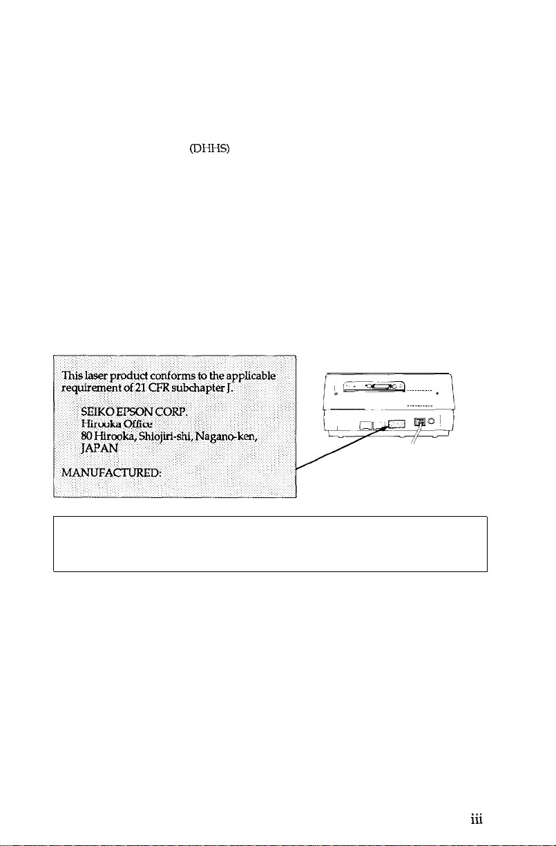
CDRH Regulations
The Center for Devices and Radiological Health (CDRH) of the US. Food and Drug
Administration implemented regulations for laser products on August 2,1976. These
regulations apply to laser products manufactured from August 1,1976. Compliance is
mandatory for products marketed in the United States.
compliance with the CDRH regulations and must be attached to laser products marketed
in the United States.
The label shown below indicates
CAUTION:
Use of controls, adjustments or performance of procedures
other than those specified in the manual may result in hazardous
radiation exposure.
..a
ill

Contents
Introduction
Chapter 1
Setting Up
Unpacking the Printer
1-1
Finding a Place for the Printer
1-1
Installing the Drum Cartridge
1-2
Installing the Toner Cartridge
1-6
Installing the Paper Tray
1-9
Loading Paper
1-9
Turning On the Printer
1-12
Operating the Control Panel
1-12
1-14
The Indicator Lights
Running a Self Test
1-15
Chapter 2
Starting Printing
2-1
Removing the Interface
2-3 Setting Switches
2-7
Connecting the Printer to a Computer
2-8 Using the GQ-3500 with Application Programs
Chapter
SelecType
3-1
3-3 SelecType Functions and Options
3-6 SelecType with DIP Switches or Software Commands
3-6 Using Optional IC Cards
Contents
3
Entering SelecType Mode
V

Chapter 4
Paper
4-1
Paper Delivery Choices
4-2 Types of Paper
4-3 Considerations in Selecting Paper
4-3 Sizes of Paper
Choosing a Standard Paper Size
4-4
Loading the Paper Tray
4-4
4-4 Hand-Feeding Paper
Clearing Paper Jams
4-5
Chapter 5
Maintenance and Status Messages
5-1 Status Messages
IC Card Status Messages
5-3
Paper Status Messages
5-4
5-7 User Maintenance
5-15 Service Maintenance
Corrective or Preventive Maintenance
5-16
5-16 Transfer Charger Wire
Chapter 6
Software Control of Printer Features
6-1
Using BASIC
6-2 Orientation
6-3 Font Selection
6-5 Character Attributes
6-7 Ruled Lines
6-9 Graphics Primitives
Appendix A
Command Summary
A-2 Comman
Page Printer Commands
A-5
A-37 LQ Emulation Commands
A-55 Line Printer Commands
ds in Numerical Order
Appendix B
Directory of Status Messages
Appendix C
DIP Switches
vi
Contents

Appendix D
Character Tables
Appendix E
Specifications
E-1 Printing
Paper and Paper Delivery
E-2
E-2 Mechanical
E-3 Electrical
E-3 Controller Hardware
E-4 Environment
E-4 Transportation
Appendix F
Parallel Interface
DIP Switch 4
F-1
Parallel Interface Jumpers
F-2
F-3 Pin Assignments
GQ-3500 Options
Contents
vii
Introduction
The Epson GQ-3500 Laser Printer combines a semiconductor laser
with the electrophotographic technology used in office copiers to give
you printing that is high quality, quiet, and fast.
Before you set up your printer, take a few minutes to look at the
illustrations in this introduction. The captions name and briefly
describe the basic parts of the outside of the printer.
you in following the setup steps in Chapter 1.
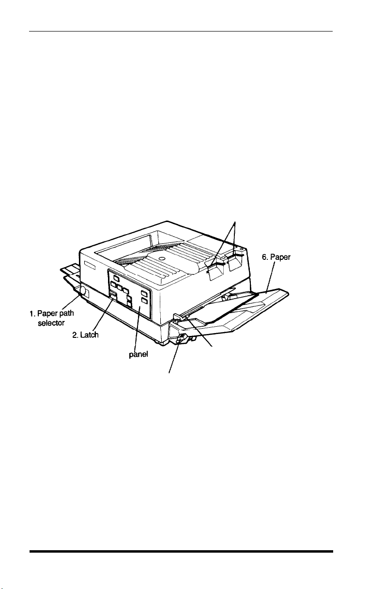
The first illustration shows the front and the right side of the
printer with the major parts identified.
This will help
7.IC card slots
tray
3. Control pknel
4. Paper set lever
1.
Paper path selector. Selects
either faceup or facedown delivery
of printed pages
2.
Latch.
Used to open the printer
3.
Control panel. Has
buttons for controlling the printer and
indicators for displaying its status
4.
Paper set lever. Used for loading paper
5.
Manual feed paper guide.
Guides paper for manual feed
Introduction/GQ-3500
5.
Manual feed paper guide
Intro-1
6.
Paper tray. Holds paper for automatic feed printing
IC card slots. Sockets for optional IC cards, which add additional
7.
fonts and operating modes to the GQ-3500
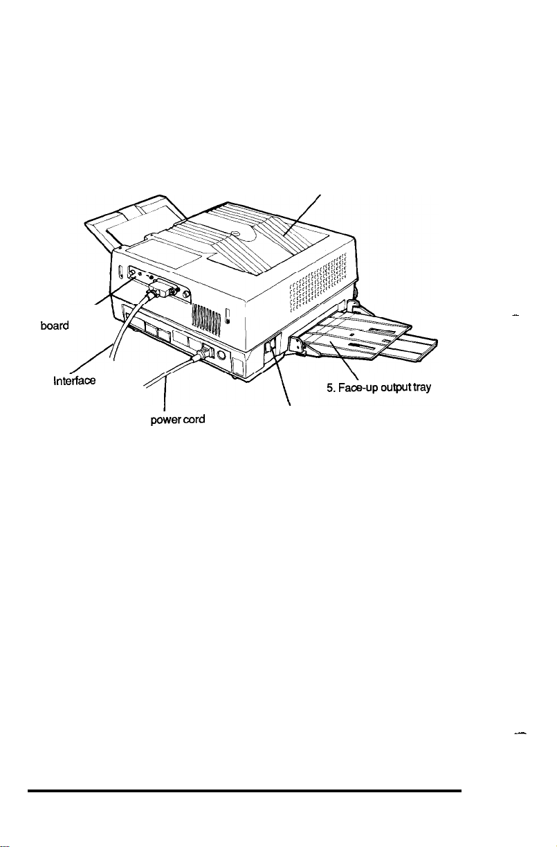
The illustration below shows the back and left side of the
GQ-3500.
6. Face-down tray
1. Interface/
board
2.
In&face
cable
Interface board. A parallel interface is supplied with the printer;
1.
yh
3. AC poher
cord
4. Power switch
a serial interface is available as an option
Interface cable. Used for
2.
AC power cord. Supplies power to the printer
3.
Power switch. The 1 side of this switch turns the printer on;
4.
connecting
the printer to a computer
the 0 side turns it off
Face-up output tray. Receives printed pages when face-up
5.
delivery is selected
Face-down tray. The printer’s top cover also serves as its print exit
6.
tray for face-down delivery
-
Intro-2
-
Introduction/GQ-3500

Laser Printer Precautions
because the GQ-3500 is a laser printer using electrophotographic
technology, certain precautions are necessary to ensure safe and
efficient operation. The following list of precautions applies whenever
you open the printer case.
printers, be sure to familiarize yourself with these precautions.
1.
Be careful not to touch the fusing unit, which is marked by a
CAUTION: HOT SURFACE
2. Protect the light-sensitive drum from exposure to light. The drum
should not be exposed to any light stronger than room light.
Furthermore, the drum should not be exposed to room light for
longer than five minutes. If you must expose the drum for more
than five minutes, either by taking the drum out of the printer or
by leaving the printer case open, cover the drum area with a soft
cloth or paper.
Even if you are familiar with other types of
label.
3. Avoid pressing on the top of the toner cartridge.
on the cartridge may cause toner powder to spill into the printer.
Pressing directly
If
there is a spill, the toner must be removed by a small vacuum
cleaner.
4. Be sure to raise the cover completely when you open the printer. If
the cover is not fully raised when you are servicing the printer
(such as clearing a paper
jam),
damage could result from printer
parts colliding with the cover or the delicate lens shield contained
in the cover.
Introduction/GQ-3500
Intro-3

Chapter 1
Setting Up
To set up your GQ3500 printer simply follow the steps in this
chapter.
1 Unpacking the Printer
Carefully unpack the carton. At the top of the carton is a box
containing several printer components. Beneath that box is the printer
itself, which is protected by white foam packing material.
After you take out the inner box where you found this manual, do
not open the smaller boxes that are inside of it. Instead, carefully
remove the printer from the large carton. See that neither the printer
nor any of the smaller boxes have been damaged during transportation.
Remember
Do not open any of the small boxes and do not plug in or turn on the
printer yet.
When you are finished unpacking, put the packaging materials
including the desiccant bag in the carton and keep them in case you need
to transport the printer. Full details on transporting the printer are in
Appendix E.
2 Finding a Place for the Printer
Now you must find a place for the printer. It must be close enough
to the computer for the cable to reach. Proper operation of the printer
also requires a certain amount of space.
If you’re going to put your printer near a wall or large piece of
furniture, such as a filing cabinet, remember to leave enough space for
operation and maintenance.
You need at least 40 inches in front of the printer (the side with
the control panel), 15 inches on the right, 4 inches on the left (16 inches
if you use the faceup output tray), and 12 inches behind.
Setting Up

Also keep the following tips in mind:
.
Place the printer on a flat, stable surface.
.
Choose a place that is clean and free from excessive heat
(including direct sunlight), moisture, and dust.
.
Use a grounded outlet - one that has three holes to match the
power plug on the printer.
l
Avoid sockets on the same circuits with large motors or other
Don’t use an adapter plug.
appliances that might disturb the power supply.
.
Keep your entire computer system away from potential sources of
interference such as the base units of cordless telephones.
When you have found a place for the printer, place the function
table sticker on the top of the printer in the location indicated in
Figure l-l.
Figure 1-1. Function table location
Function
3 Installing the Drum Cartridge
Before you use the printer, you must install a few important parts
that are packaged separately for safe transportation. The first is the
drum cartridge.
1-2
Setting Up
WARNING
Do not expose the drum cartridge to any light brighter than normal
room light, and do not expose it to room light for more than five
minutes. Leave it boxed until you have read over the next few pages
and know how to install it. Also, do not touch the surface of the drum or
let it rest on any hard surface that might scratch it.
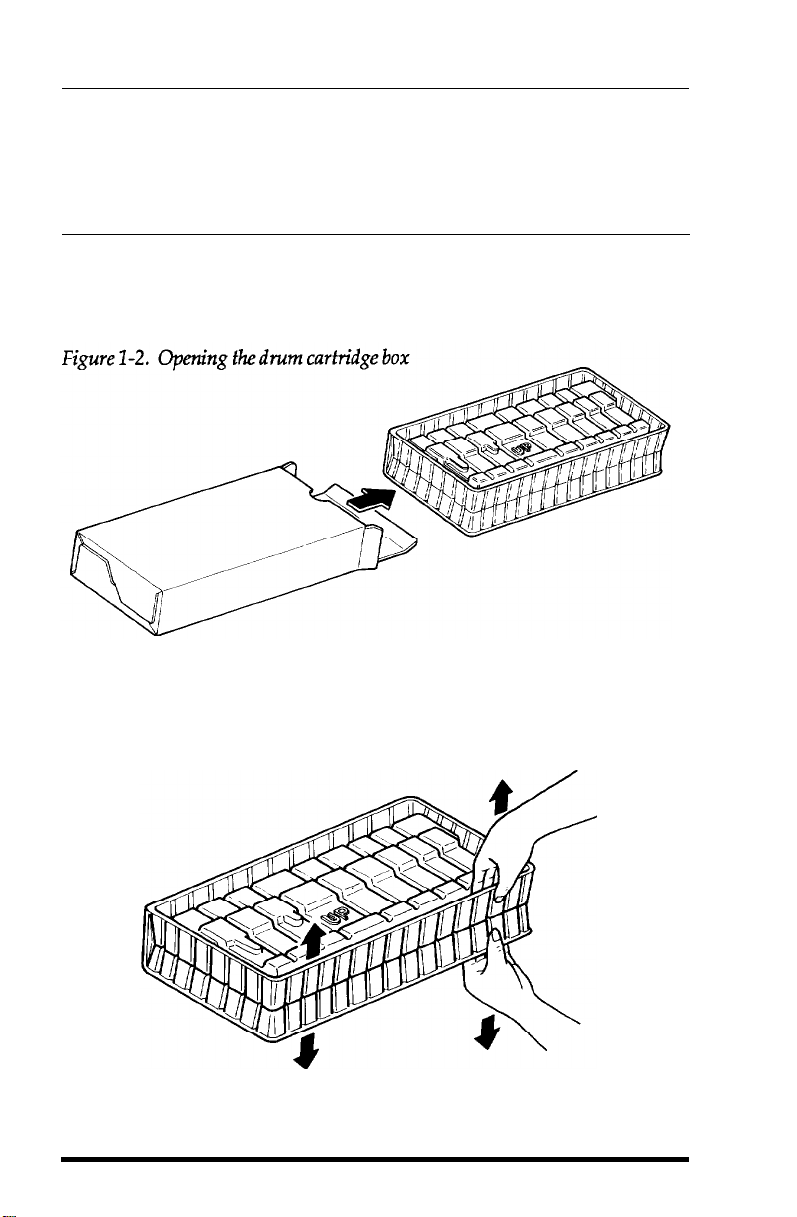
Open the drum cartridge box and pull out the plastic container, as
shown in Figure 1-2.
(The plastic bag inside the box is for eventual
disposal of the cartridge when it has to be replaced.)
See that the side of the plastic container marked UP is up, and
carefully open the plastic container as shown in Figure 1-3.
Figure 1-3. Opening the container
Setting Up
1-3
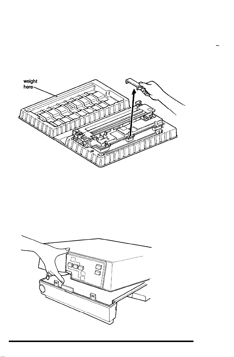
Because the top of the plastic container does not stay open by itself,
put a small object on the top to hold it open, as indicated in Figure 1-4.
Then remove the orange holder.
It is needed only for transportation.
Figure 1-4. The open container
Place
-
Now you are ready to install the drum cartridge.
1.
Lift up on the latch on the front of the printer and open the printer.
Follow these steps:
(See Figure 1-5.)
Figure 1-5. Opening the printer
1-4
Setting Up

2.
Hold the drum cartridge by the two green tabs and lift it out of the
plastic container. Then be sure that the drum is toward the right
side of the printer, and lower the cartridge into the opening to the
left of the block of white foam packing material (as shown in
Figure 1-6).
Figure 1-6. Installing the drum cartridge
3.
Lower the cartridge into the printer until it fits into place. Then
press the green tabs back to the horizontal position.
4.
Press the reset lever at the left rear of the inside of the printer, as
shown in Figure 1-7. This is important because the reset lever
resets the counter that keeps track of the usage of the drum
cartridge.
Setting Up
1-5
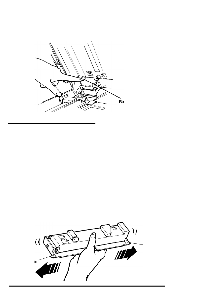
Figure 1-7. Pressing the reset lever
set lever
4 Installing the Toner Cartridge
The toner cartridge must be installed in the developing unit (which
is already in the printer). Follow these steps:
1.
Remove the block of white packing material from the developing
unit (to the right of the drum cartridge).
2.
Next take the toner cartridge out of its box. Remove the take-up
handle and the tape from the top of the cartridge.
3.
Shake the toner cartridge back and forth several times
horizontally, as shown in Figure 1-8. This distributes the toner
evenly in the cartridge.
Figure
1-8. Distributing
Pi
1-6
the toner
Pin
Setting Up
Caution
Do not press on the top of the toner cartridge because toner may spill
into the printer. Instead press on the edge of the cartridge as shown. If
toner spills into the printer, remove it with a small vacuum cleaner.
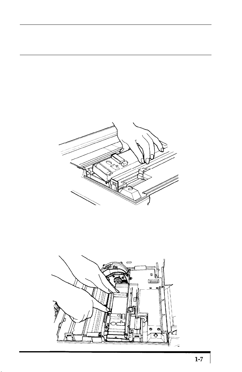
On the bottom right side of the toner cartridge are two pins, one at
4.
each end. (See Figure 1-8.) Hold the toner cartridge vertically
with the pins at the bottom and lower the pins into the notches in
the developing unit. Then tilt the cartridge into place, as shown in
Figure 1-9.
Figure 1-9. Installing the toner cartridge
Now hold the green toner cartridge lock lever down while you
5.
lower the left side of the toner cartridge. Then release the lock
lever to lock the cartridge into place as shown in Figure 1-10.
Figure 1-10. Locking the cartridge info place
Setting Up
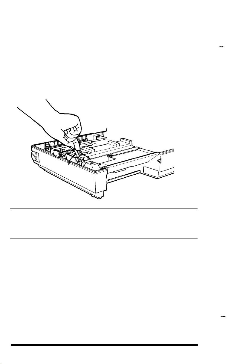
6.
Attach the seal take-up handle to the small plastic shaft at the
front of the toner cartridge. (See Figure 1-11.) Move the lever back
and forth (in the direction of the arrows in Figure 1-11) until it
won’t move any further with moderate pressure.
markings on the seal when you reach the end of it.) This step,
which may take up to 40 back and forth movements of the handle,
peels back the toner seal and releases the toner into the developer.
Figure 1-11. Removing the toner seal
(You will see red
Caution
Once the toner cartridge has been installed, do not remove it until you
are prompted to do so by the TONER OUT light on the control panel.
Otherwise toner will spill into the printer.
7.
Remove and discard the take-up lever.
8.
Tap each of the corners of the toner cartridge to prevent toner from
remaining in the comers of the cartridge.
9.
Make sure that the developer unit is properly locked into place by
pressing on the two places marked by blue dots. They are to the
right of the toner cartridge.
Now that you have installed the internal components, close the
printer and gently press down on the top of the case until the latch
clicks shut.
1-8
Setting Up
5 Installing the Paper Tray
before you install the paper tray, remove all of the packing
material, including any white foam and pieces of tape. Then follow
these steps:
1.
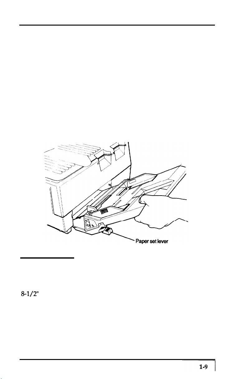
Push down the paper set lever until it clicks into place. (See Figure
1-12 for the location of the paper set lever.)
2.
Hold the paper tray as shown in Figure 1-12. Notice that it is at
an angle. Slide the plastic runners on either side of the paper tray
into the black grooves inside the printer.
installed, the tray clicks into place.
Figure 1-22. Installing the paper fray
When properly
6 Loading Paper
Chapter 4 contains complete information about choosing paper
types and sizes. For now, simply use up to 150 sheets of ordinary
&l/2” x 11” white paper. (Xerox® 4024 copier paper is preferred.)
1.
See that the paper set lever is down, and open the paper guides all
the way. (See Figure 1-13.)
Setting Up
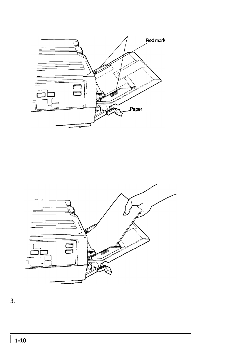
Figure 1-13.
Paper set lever and guides
Paper guides
w
2.
Insert a stack of paper into the tray, making sure that the top of
&Maper
set lever
the stack does not cover the red mark on the inside of the paper
tray.
Push the paper in gently as far as it will go, as shown in
Figure 1-14. (The paper will feed more easily if you fan it before
you load it.)
Figure 1-14.
Loading paper
Slide the paper guides together until they are both against the
edges of the stack of paper. (See Figure 1-15.) Then raise the paper
set lever to the up position.
Setting Up
--
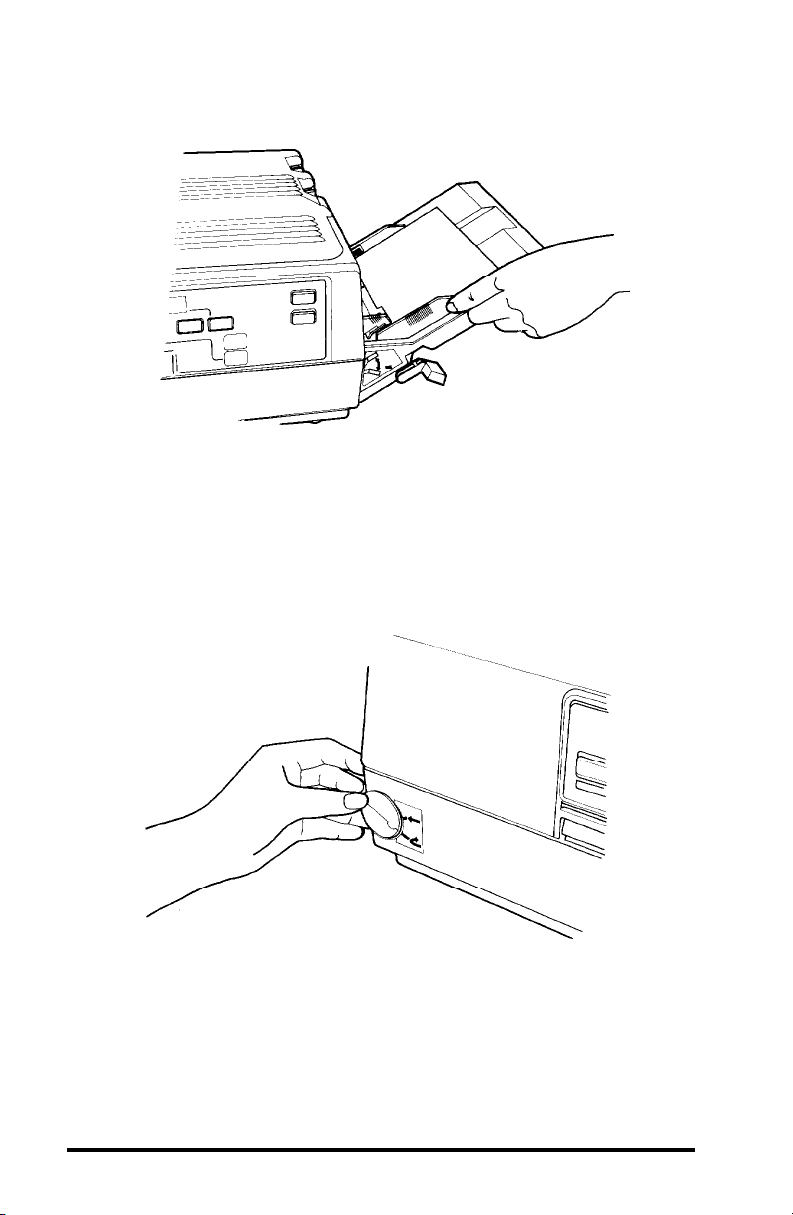
Figure 1-15.
Adjusting
the paper guides
4. Set the paper exit path with the paper path selector at the bottom
left of the front of the printer.
delivery by turning the dial down as shown in Figure 1-16.
Set the path for facedown
With
this setting the paper will exit at the top of the printer.
Figure 1-16. Setting paper path
When ejected facedown, the pages are stacked in the order in
which they are printed.
the use of the face-up output tray.
The other setting for paper delivery requires
because you do not need to use it now,
the installation and use of that tray is explained in Chapter 4.
Setting Up
1-11
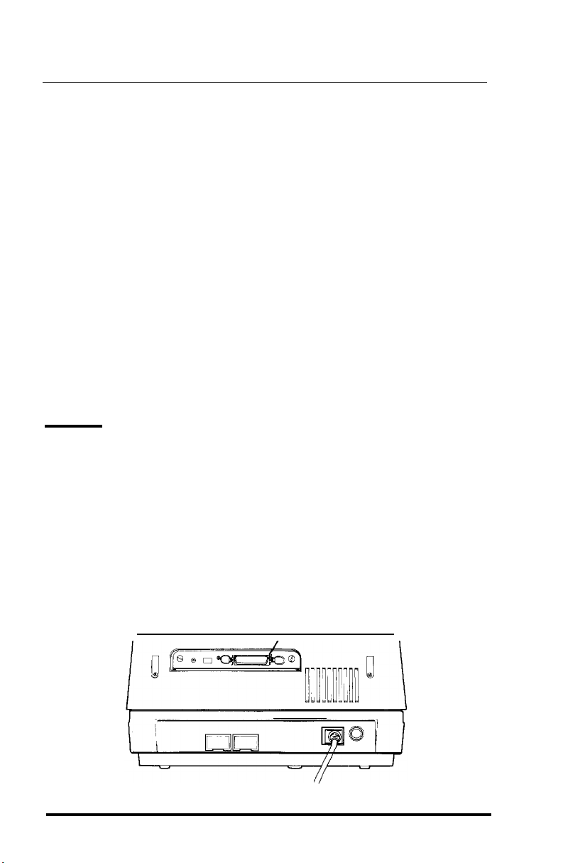
7 Turning On the Printer
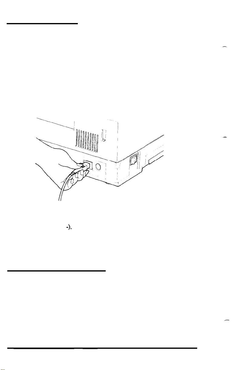
1.
before attaching the power cord, make sure the power switch on
the left side of the printer (see Figure 1-17) is turned off. (It is off
when the 0 side of the switch is pushed in.)
2.
Attach the power cord at the back of the printer as shown in Figure
1-17. Then plug the power cord into a properly grounded outlet.
Figure 1-17. Attaching
3.
Turn the power ON with the power switch. The
the
power cord
STATUS
indicator
on the control panel displays the warm-up symbol, which is two
horizontal lines (-
-).
The warm-up symbol flashes to show that
the printer is warming up. After about 45 seconds, the warm-up
symbol stops flashing, meaning that the printer is ready to
operate. The
POWER, READY,
and
ON LINE
indicators on the
control panel should also be on.
-
8 Operating the Control Panel
The GQ-3500 control panel (shown on the next page in Figure 1-18)
has five buttons, nine indicator lights, and the
LED (Light-Emitting Diode) that can display two numbers or letters.
The bottom half of the panel lists some of the common status messages
and their meanings.
1-12
STATUS
indicator, an
Setting Up
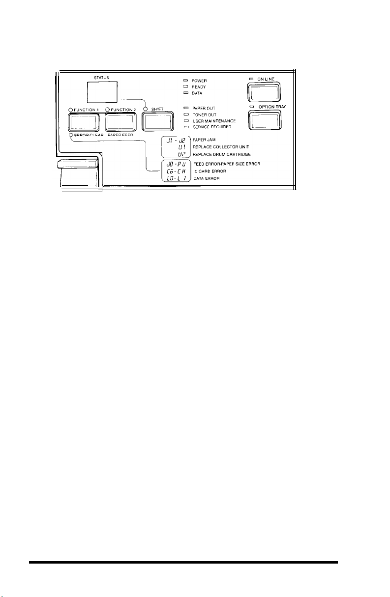
Figure 1-18. The control panel
From this panel you can control almost all the printer functions.
ON LINE
The
ON
LINE button switches the printer between the on line and
off line states. In the on line state, the ON LINE light is on. This means
that the printer can receive and print data (if the POWER and READY
lights are also on).
In the off line state, the ON LINE light is not on, nor is the READY
light on.
In this state, you can enter the SelecType mode, as explained
in Chapter 3.
FUNCTION l/ERROR CLEAR
This button has several uses:
l
Clearing the printer to correct an error condition
l
Continuing printing after clearing a paper jam.
.
Entering the test mode and changing test patterns.
l
Selecting functions in the SelecType mode.
Setting Up
1-13

FUNCTION 2/PAPER FEED
This button also has several uses:
.
Printing out any data received and ejecting the paper.
.
Feeding the paper during a printer self test.
l
Selecting details for each function in the SelecType mode.
Note
Because they have so many functions, these two buttons have two names
each. This manual uses whichever name is appropriate to the
operation being described. For example, the button on the left is called
the
ERROR CLEAR
called the
FUNCTION 1
button when error messages are discussed, but it is
button when selecting functions in SelecType is
described.
SHIFT
When
the printer is off line, this button selects or cancels the
SelecType mode, described in Chapter 3. This button also stops the
printing of multiple copies when the printer is off line.
The Indicator Lights
In addition to the lights above the
ON LINE
and
OPTION TRAY
buttons, the printer has seven other indicator lights.
POWER
READY
DATA
-
Indicates that the printer is turned on and receiving power.
-
Lights when the printer is ready to receive data.
-
Flashes rapidly when data is being received from the host
computer. When no data is being received, it flashes slowly. When
the printer buffer is empty, the light is off.
PAPER OUT
TONER OUT
-
Rashes when the paper tray is out of paper.
-
Flashes when the toner drops below a certain level.
This is an indication that you need to change the toner cartridge.
USER MAINTENANCE
or the collector unit needs to be replaced.
-
This light indicates that the drum cartridge
The
STATUS
display code
tells you which one to replace. (See Chapter 5 for a full explanation.)
1-14
Setting Up
SERVICE REQUIRED
are detected. The
malfunction. See Chapter 5 for full information on
REQUIRED
messages.
- Flashes when certain printer malfunctions
STATUS
display shows the code for the specific
SERVICE
STATUS
display
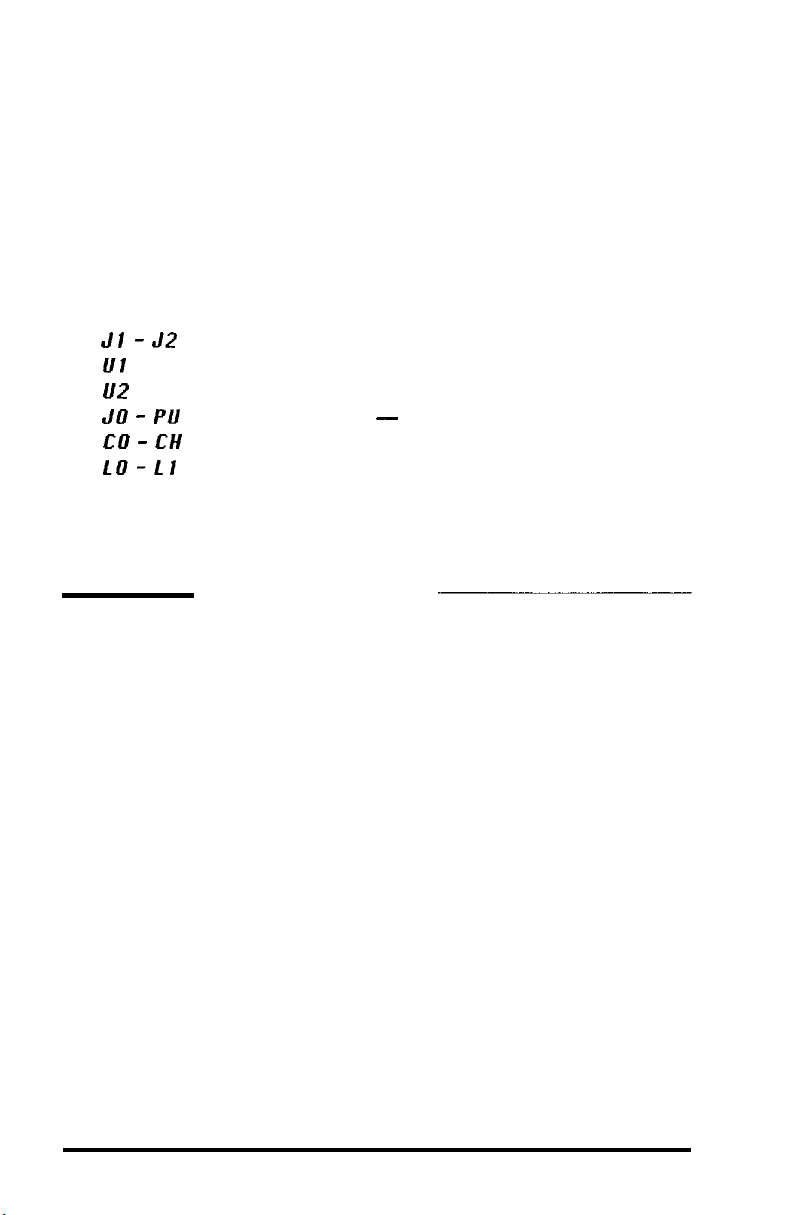
The STATUS
display shows many different messages. Some
common status message codes are shown on the control panel for easy
reference.
Jl -J2
Ul
l/2
JO - PU
CO - CH
LO-L1
PAPER JAM
REPLACE COLLECTOR UNIT
REPLACE DRUM CARTRIDGE
FEED ERROR - PAPER SIZE ERROR
IC CARD ERROR
DATA ERROR
Each of these messages and what you need to do about it is
discussed in this manual, and all of them are listed in Appendix B.
9 Running a Self Test
The GQ-3500 has two built-in self tests so that you can be sure the
printer is working properly.
Before running a self test, see that the paper is loaded correctly
and the power is OFF.
1.
Hold down the
FUNCTION 1
button while you turn the power on.
Release the button when the warm-up symbol (- -) begins to flash
in the
STATUS
display. The warm-up symbol flashes until the
printer is ready and then the message OC appears. Press the
FUNCTION 1
Setting Up
button once again.
1-15
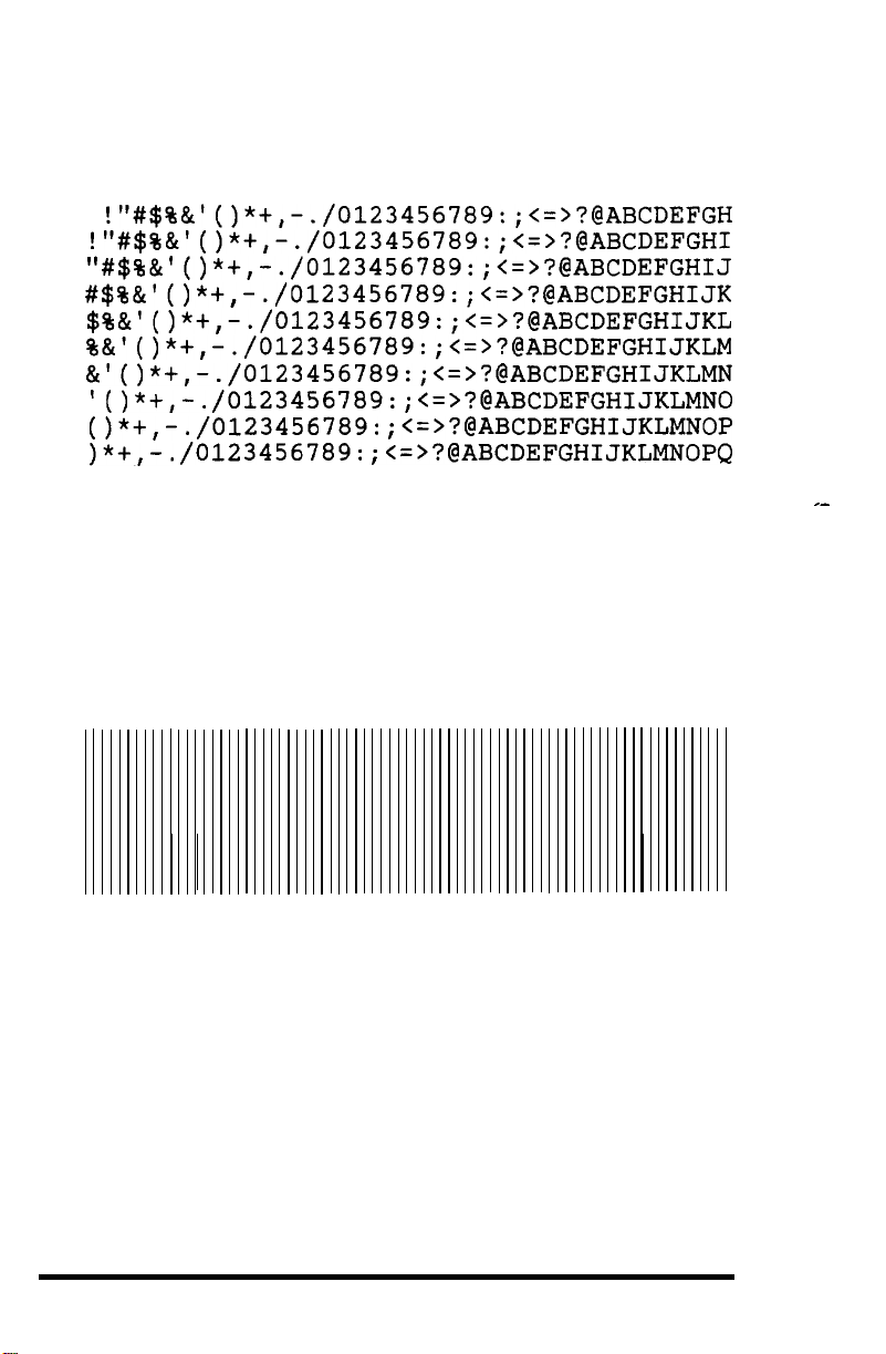
2.
Press the FUNCTION
will flash until the page is ejected from the printer. You will see a
sample of the printer’s characters like this one:
2 button
to start the self test. The 1C message
!"#$%&I()*+,-./0123456789:;<=>?@ABCDEFGH
!"#$%&I()*+,-./0123456789:;(=>?@ABCDEFGHI
"#$%&'()*+,-./0123456789:;<=>?@ABCDEFGHIJ
#$%&'()*+,-./0123456789:;<=>?@ABCDEFGHIJK
$%&'()*+,-./0123456789:;<=>?@ABCDEFGHIJKL
%&'()*+,-./0123456789:;<=>?@ABCDEFGHIJKLM
&I()*+,-./0123456789:;
lo*+,-.
o*+,-.
>*+,-.
3.
Press the FUNCTION
which is indicated by
4.
Press
the FUNCTION
will flash until the page is elected from the printer. The test
shows a pattern of lines like this:
/0123456789:;
/0123456789:
/0123456789:
1 button to change to the other self test,
OC on the STATUS
2 button to start the second self test. The OC
<=>?@ABCDEFGHIJKLMN
<=>?@ABCDEFGHIJKLMNO
;<=>?@ABCDEFGHIJKLMNOP
;<=>?@ABCDEFGHIJKLMNOPQ
display.
_-
5.
Once you have seen that your printer is printing normally, turn the
printer off.
The GQ-3500 comes equipped with a
parallel interface. If your computer can communicate through a
parallel interface, all you need is the proper shielded cable. If your
computer requires a serial interface, see your dealer for
serial interface available for this printer. The serial interface contains
its own instructions. If you don’t know what kind of interface your
computer requires, consult your dealer or your computer manual.
1-16
Centronics®
compatible
the
optional
Setting Up
Chapter 2
Starting Printing
Now that you have set up your GQ-3500 and tested it to make sure
it is working properly, you need to do three things before you start
printing:
Set switches that change some of the printer’s settings to suit your
l
individual
Connect the printer to your computer
.
Set up your application programs for the GQ-3500.
l
It is best to read this entire chapter before you begin changing
switch settings.
Also, whether you are using a parallel or a serial interface, the
DIP switches described in this chapter are the same.
Removing the Interface
Before you change any switch settings, you must remove the
interface from the printer. This doesn’t require any tools. Just follow
these steps:
needs
1.
Locate the interface on the back of the printer.
shown in Figure 2-1.
Figure 2-1. Interface location
Interface board
Starting Printing
Its position is
2-1
2. Make sure that the power to the printer is turned off and that no
cable is connected from the printer to the computer.
3. Loosen the two knobs and pull the interface straight out as shown
in Figure 2-2.
Figure 2-2. Removing the interface
Knob
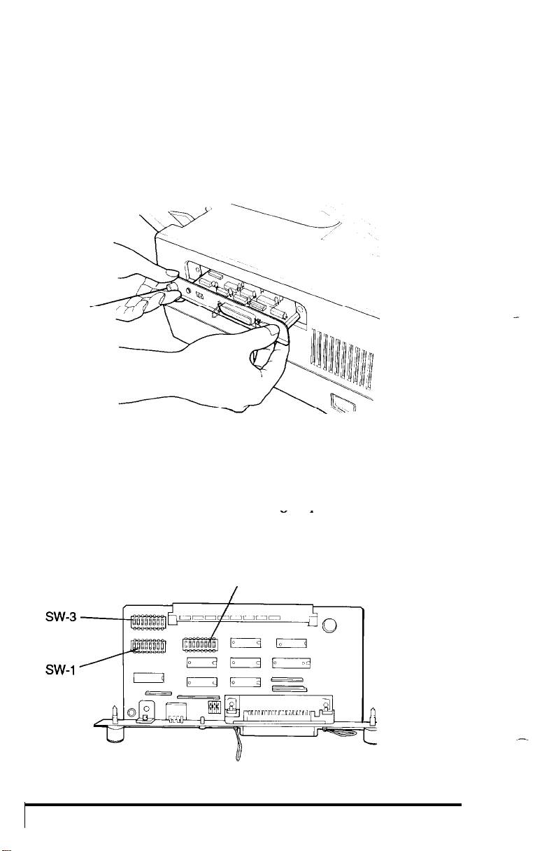
4. Locate the switches on the interface board. The two groups of DIP
switches (see Figure 2-3) are labeled SW 1 and SW 2. Each of the
individual switches also has a small number, from 1 to 8. The
individual switches are referred to by group and number: thus, the
switch with the small number 4 in the group labeled SW 1 is called
switch 1-4.
Figure 2-3. Dip switch location
SW-2
/
-
2-2
Starting Printing

Setting the DIP switches
Use the tip of a ballpoint pen or another small pointed object to
turn the switches ON or OFF.
Setting Switches
This section first describes the main choices you have and then it
tells you how to reset the appropriate switches.
Choosing an operating mode
The GQ-3500 has four operating modes:
Page printer-gives
such features as forms overlays, double-high and triple-high printing,
and graphics primitives. (Chapter 6 contains full details.)
Epson LQ
requires you to use an Epson LQ printer.
Line printer-
allows 66 lines with 136 columns on standard letter size paper, using a
special character set with 13 characters per inch (cpi). The page
printer mode, however, can also print this material. See Chapter 3 for
instructions on using SelecType to put more characters on a page. To
select an operating mode, set switches 1-1 and 1-2 as shown in Table 2-1.
IC card-allows the use of optional IC cards that provide other
operating modes.
instructions with it.
and see whether the GQ-3500 prints properly with your application
programs.
Table 2-1.
emulation - for use with an application program that
If you are not sure which mode to use, use the page printer mode
To select an operating mode, set switches 1-1 and 1-2 as shown in
access to all the printer’s capabilities, including
can be used for printing simple text or spreadsheets.
If you buy an optional IC card, you receive full
It
Starting Printing
2-3

Table 2-1.
Settings for operating mode
1-1
1-2
Automatic reprint when paper jams
When a paper jam occurs, the page being printed is sometimes
spoiled. If switch 1-3 is ON, the printer automatically reprints pages
that jam.
Setting this switch ON may slow
If this switch is OFF, the jammed page is not reprinted.
the
printing speed because
the
printer’s memory buffer retains the data describing the page being
printed until it has finished printing it.
Non-printable codes
Switch 1-4
receives but does not recognize as a printing character.
controls
what
the printer does with codes that it
If this switch is
ON, a space character is substituted for the unknown code to leave
space in the line for you to put the character in manually.
If this
switch is OFF, the unrecognized code is just ignored and no space is left.
Automatic line feed
When switch 1-5 is ON,
carriage return; when it is OFF, it does not.
the
printer adds a line feed to each
If your printing has an
extra space between lines, turn this switch OFF. If your printed lines
are on top of each other, turn this switch ON.
Automatic carriage return
When switch 1-6 is ON the printer starts a new line (by inserting a
carriage return
right margin. If this
line
are discarded.
and
line
feed)
if
it receives a line
switch
is OFF, any characters that don’t fit on a
that
extends past the
Automatic form feed
When switch 1-7 is ON, the printer starts a new page if it receives
more
lines than
will fit on the current page.
If this switch is OFF, the
printer will not start a new page until it receives a form feed code.
2-4
Starting Printing
 Loading...