

Page 1
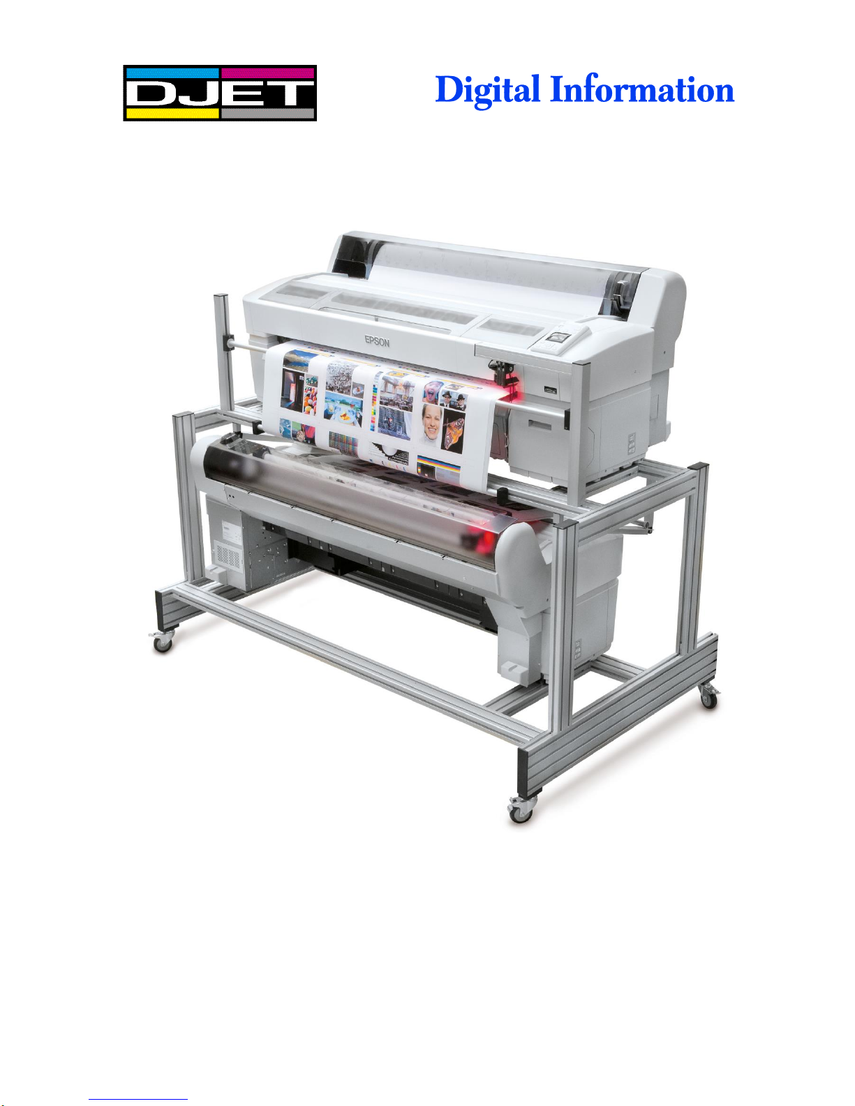
D-Jet 300 / 500 / 700
Installation Manual
Page 2

Digital Information
Technoparkstrasse 1
CH-8005 Zürich
© Copyright by Digital Information Ltd. 2013
This manual is proprietary in nature and the sole property of
Digital Information. It may not be reproduced, in whole or in part,
without the express written permission of Digital Information.
Digital Information reserves the right to modify and/or delete any
material and/or capabilities described herein.
All the documentation in this manual is instructional and for the
operation of DJet machine. Digital Information shall not be
responsible for any damage or claims resulting from any errors or
omissions in this manual.
Owning to our policy of continuous product development,
specifications, terms and description of DJet 300/500/700 are
subject to change without prior notice.
.
Identifier Hardware Installation manual - EN
Target group Service Engineer
Product D-Jet 300 / 500 / 700
Version V2.0
Date November 2013
Article code DJet IM7890-001 EN
Page 3

Table of contents
DJet 300-500-700 – HW Installation Manual I
Table of contents
1 Introduction .................................................................................................................................... 1-1
2 Safety............................................................................................................................................... 2-1
2.1 Warning ............................................................................................................................................ 2-1
3 Pre-Installation Tasks .................................................................................................................... 3-2
3.1 Tools Required ................................................................................................................................. 3-2
3.2 PC Specification ............................................................................................................................... 3-2
3.3 Additional Materials Required .......................................................................................................... 3-2
3.4 Unpacking ........................................................................................................................................ 3-3
4 Frame Setup ................................................................................................................................... 4-1
4.1 DJet 700 / DJet 500 Setup ............................................................................................................... 4-1
4.2 Frame Parts...................................................................................................................................... 4-2
4.3 DJet 300 Setup ................................................................................................................................ 4-3
4.4 Frame Parts...................................................................................................................................... 4-4
5 Frame Assembly............................................................................................................................. 5-1
5.1 Base Plates ...................................................................................................................................... 5-1
5.1.1 Parts .................................................................................................................................. 5-1
5.1.2 Assembly .......................................................................................................................... 5-2
5.2 Side Frame ....................................................................................................................................... 5-3
5.2.1 Parts .................................................................................................................................. 5-3
5.2.2 Assembly .......................................................................................................................... 5-3
5.3 Cross-Beam Profile .......................................................................................................................... 5-5
5.3.1 Parts .................................................................................................................................. 5-5
5.3.2 Assembly .......................................................................................................................... 5-6
5.3.3 Measurements for DJet 300 / 23“ Version ........................................................................ 5-8
5.3.4 Measurements for DJet 500 / 35“ Version ........................................................................ 5-9
5.3.5 Measurements for DJet 700 / 43“ Version ...................................................................... 5-10
5.3.6 Tighten all Profiles .......................................................................................................... 5-11
5.4 Wheels ........................................................................................................................................... 5-11
5.4.1 Parts ................................................................................................................................ 5-11
5.4.2 Mount the Wheels ........................................................................................................... 5-12
5.5 Printer Base Plates ........................................................................................................................ 5-12
5.5.1 Parts for each Printer ...................................................................................................... 5-12
5.5.2 Assembly POM Parts ...................................................................................................... 5-13
5.5.3 Base Plates for Top Printer ............................................................................................. 5-14
5.5.4 Position the Base Plates Front Printer ............................................................................ 5-16
Page 4

Table of contents
II DJet 300-500-700 – HW Installation Manual
5.5.5 Base Plates for Bottom Printer ....................................................................................... 5-16
6 Prepare BACK Printer .................................................................................................................... 6-1
6.1 Paper Roll Holder Guide Epson ....................................................................................................... 6-1
6.2 Base Profile for Paper Guide and Camera Holder ........................................................................... 6-4
6.2.1 Additional Parts ................................................................................................................. 6-4
6.2.2 Assembly .......................................................................................................................... 6-5
7 Paper Entry Guide / Camera System .......................................................................................... 7-10
7.1 Side parts - Step 1 .......................................................................................................................... 7-10
7.1.1 Parts ................................................................................................................................ 7-10
7.1.2 Assembly ........................................................................................................................ 7-11
7.2 Side Parts - Camera Holder BACK Printer .................................................................................... 7-11
7.2.1 Parts ................................................................................................................................ 7-11
7.2.2 Assembly ........................................................................................................................ 7-12
7.3 Assembly „Right Holder“ and „Camera holder“ .............................................................................. 7-13
7.3.1 Parts ................................................................................................................................ 7-13
7.3.2 Assembly ........................................................................................................................ 7-13
7.4 Paper Guide Entry to BACK printer ............................................................................................... 7-13
7.4.1 Parts ................................................................................................................................ 7-13
7.4.2 Side Holders to Base Profile ........................................................................................... 7-14
7.5 Paper Guide Roller ......................................................................................................................... 7-15
7.5.1 Parts ................................................................................................................................ 7-15
7.5.2 Paper Guide Roller ......................................................................................................... 7-16
7.6 Angled Paper Bracket for Printer Back .......................................................................................... 7-17
7.6.1 Parts ................................................................................................................................ 7-17
7.6.2 Assembly ........................................................................................................................ 7-18
7.7 „Paper Jam Protector” .................................................................................................................... 7-19
7.7.1 Parts ................................................................................................................................ 7-19
7.7.2 Positioning ...................................................................................................................... 7-20
7.7.3 Assembly ........................................................................................................................ 7-20
7.8 Camera and LED Bar Lights for Printer Front and Back ................................................................ 7-24
7.8.1 Parts for each camera system ........................................................................................ 7-24
7.8.2 Assembly ........................................................................................................................ 7-24
7.8.3 Camera Focus and Shutter Setup .................................................................................. 7-25
7.9 Camera and LED Back Printer ....................................................................................................... 7-26
7.9.1 LED ................................................................................................................................. 7-26
7.9.2 Camera ........................................................................................................................... 7-26
7.10 Camera Holder Front Printer .......................................................................................................... 7-26
7.10.1 Parts ................................................................................................................................ 7-26
7.10.2 Assembly ........................................................................................................................ 7-27
7.11 Camera and LED for Front Printer ................................................................................................. 7-28
7.11.1 Parts ................................................................................................................................ 7-28
Page 5

Table of contents
DJet 300-500-700 – HW Installation Manual III
7.11.2 Camera Holder ............................................................................................................... 7-29
8 Mount the Printers ......................................................................................................................... 8-1
8.1.1 Parts .................................................................................................................................. 8-1
8.1.2 T3000 - Rubber Foot ........................................................................................................ 8-2
8.1.3 Mount Front Printer ........................................................................................................... 8-2
8.1.4 Mount and Position Back Printer ...................................................................................... 8-3
8.1.5 Lock the Printer ................................................................................................................. 8-3
9 Paper Tension Guide and Deflection Rollers .............................................................................. 9-1
9.1 Paper Tension Guide ........................................................................................................................ 9-1
9.1.1 Parts for Paper Tension Guide .......................................................................................... 9-1
9.1.2 Tension Guide, Right Side ................................................................................................ 9-2
9.1.3 Tension Guide, Left Side ................................................................................................... 9-3
9.2 Lower Deflection Roller .................................................................................................................... 9-4
9.2.1 Parts .................................................................................................................................. 9-4
9.2.2 Deflection Roller Holder .................................................................................................... 9-5
9.3 Upper Deflection Roller .................................................................................................................... 9-6
9.3.1 Parts .................................................................................................................................. 9-6
9.3.2 Assembly .......................................................................................................................... 9-7
10 Line up the Printers ..................................................................................................................... 10-1
10.1 Paper Entry Back Printer................................................................................................................ 10-1
11 Printer Panel Configuration ........................................................................................................ 11-2
11.1 Parameter Setup for FRONT and BACK Printer ............................................................................ 11-2
11.2 Enable DJet Mode ........................................................................................................................ 11-12
12 LED Bar Light ............................................................................................................................... 12-1
12.1 Power Supply Setup for LED Bar Light .......................................................................................... 12-1
Page 6

Page 7

Introduction
Warning
1
DJet 300-500-700 – HW Installation Manual 1-1
1 Introduction
The DJet system is a fully automatic double-sided printing system. It is based on two Epson T-Series
SureColor 3000, 5000 and 7000.
Please note:
Installation of this equipment must be done by a trained service engineer.
Do NOT leave Epson Printers on the stand without securing them with the Printer locking devices.
Page 8

Page 9

Safety
Warning
2
DJet 300-500-700 – HW Installation Manual 2-1
2 Safety
This section provides important safety information and must be read before switching on or
operating the equipment.
2.1 Warning
All precautions mentioned in this document must be strictly observed at all times. Personnel MUST therefore
read the contents of the document BEFORE commencing any work on the equipment described in the
document.
Improper use of controls and switches, failure to comply with warnings, and the performance of adjustments
or procedures not specified in this document may expose personnel to danger.
Installation of this equipment must be done by a trained engineer.
Do NOT leave Epson Printers on the stand without securing them with the Printer locking devices.
Page 10

3
Pre-Installation Tasks
Tools Required
2-2 DJet 300-500-700 – HW Installation Manual
3 Pre-Installation Tasks
3.1 Tools Required
Standard screw driver set
Set if allen key wrench
Set of Phillips screw driver
Measurement tape
Cordless drill for unpacking the crate
3.2 PC Specification
CPU Intel i5 or i7
min. 4 GB RAM
min. 1x 500 GB hard disk drive, 7200rpm
1x 128 GB Solid State Drive
min. 4x USB ports
2x Ethernet ports
19” TFT monitor (touch screen is recommended)
Windows 7, 32/64 bit version
The PC needs to be equipped with a SSD
drive (min 128GB).
3.3 Additional Materials Required
For the DJet startup prepare the following items (not shipped by DI):
3x RJ45 Cat 5 Ethernet cable length: 3m, 3m, 5m
1x Ethernet Switch 10/100/1000 MB, min. 4 ports
2x shielded USB 2.0 cable, “USB-mini B” to “USB-A”
used for camera connection, minimum length is 2 metre
goes to USB Hub
Page 11

Pre-Installation Tasks
Unpacking
3
DJet 300-500-700 – HW Installation Manual 2-3
2x shielded USB 2.0 cable, “USB-A” to “USB-B”
used for connecting the printers via USB HUB to the PC
minimum length is 3 metre
1x shielded USB 2.0 cable, “USB-A” to “USB-B”
used for connecting the USB HUB with the PC
minimum length is 2 metre
1x active 4 port USB Hub (runs with a Power Supply)
connects the both USB cameras and printers to the PC
2x Power Cable for Epson printer
connects both printers to the power outlet strip
minimum length is 3 metre
1x Power Outlet Strip with minimum 5 outlets:
2x Printers, 1x DC Power Supply (LED Bar Lights), 1x USB Hub, 1x Ethernet Switch
3.4 Unpacking
Make sure all parts are available after unpacking the cases. Check the part list inside the shipment.
All packaged items must be inspected at the customer's site before unpacking begins. The following steps
are taken when there has been damage:
1.) Record the observations on the delivery documentation.
2.) Inform the carrier, shipping agent and insurance agent.
Units may be removed from their box only by an approved engineer or representative. Do not proceed with
unpacking when there has been a damage report until authorized by the shipping and insurance agents.
Page 12

Page 13
Frame Setup
DJet 700 / DJet 500 Setup
4
DJet 300-500-700 – HW Installation Manual 4-1
4 Frame Setup
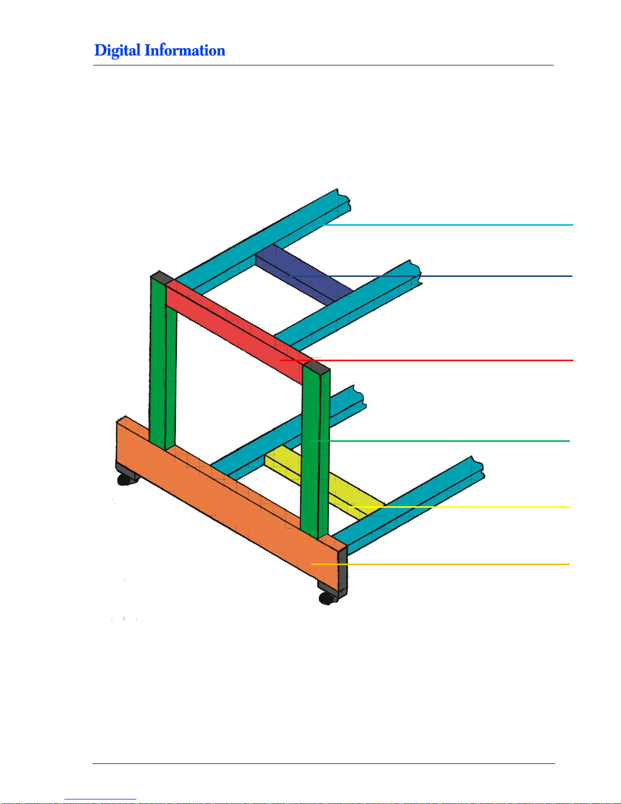
4.1 DJet 700 / DJet 500 Setup
Pos 6 – 1780 mm
Pos 1 – 1100 mm
Pos 3 – 385 mm
Pos 4 – 545 mm
Pos 2 – 675 mm
Pos 5 – 650 mm
Pos 2 – 675 mm
Page 14
4
Frame Setup
Frame Parts
4-2 DJet 300-500-700 – HW Installation Manual
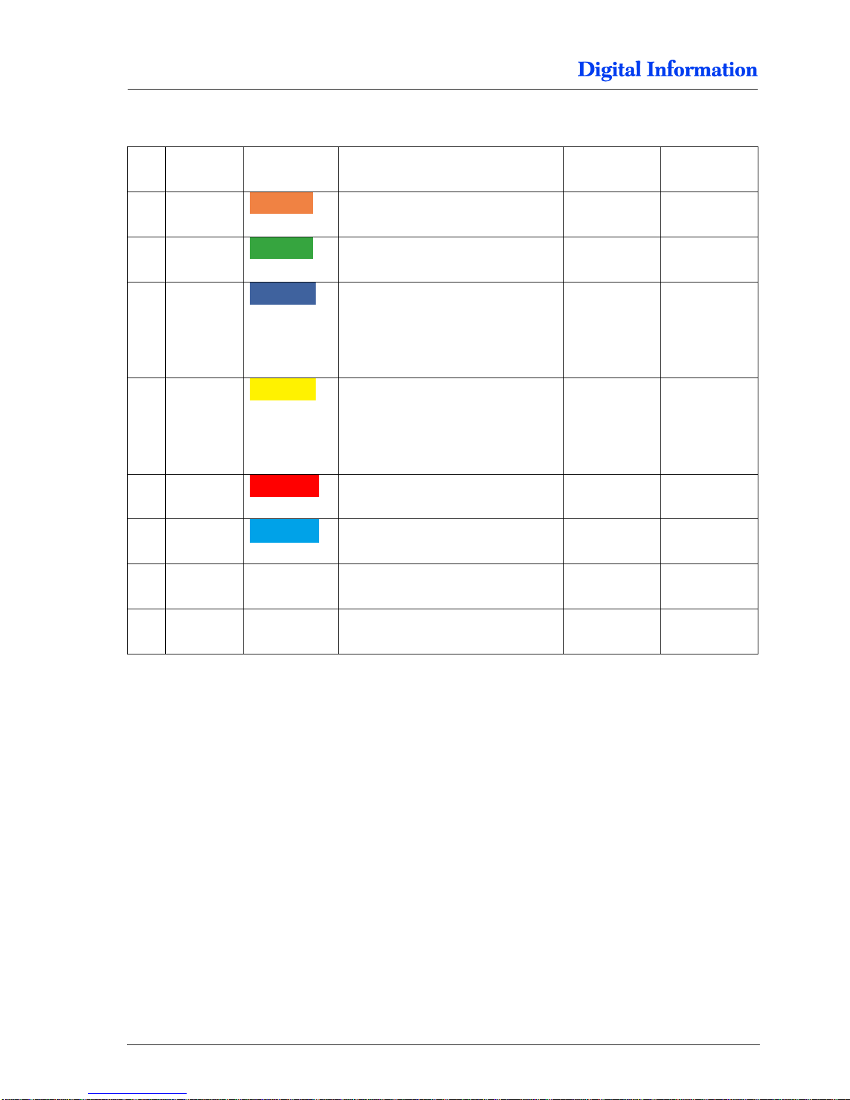
4.2 Frame Parts
Pos Amount
Color
Name
Profile in mm
Length in mm
1 2 Cross-member, 2 wheels mounted
40 x 160
1100
2
4 Pillar
40 x 80
675
3
2 Distance holder for top crossmembers, position 6.
Used to mount the Epson printer to
the stand
40 x 80
385
4
2
Distance holder for bottom crossmembers, position 6.
Used to mount the Epson printer to
the stand
40 x 80
545
5 2 Cross-member top
40 x 80
650
6 4 Cross-member for printer top /
bottom
40 x 80
1780
7 4 Base plate for swivel caster
40 x 80
8 4
Swivel caster, 75mm
Page 15
Frame Setup
DJet 300 Setup
4
DJet 300-500-700 – HW Installation Manual 4-3
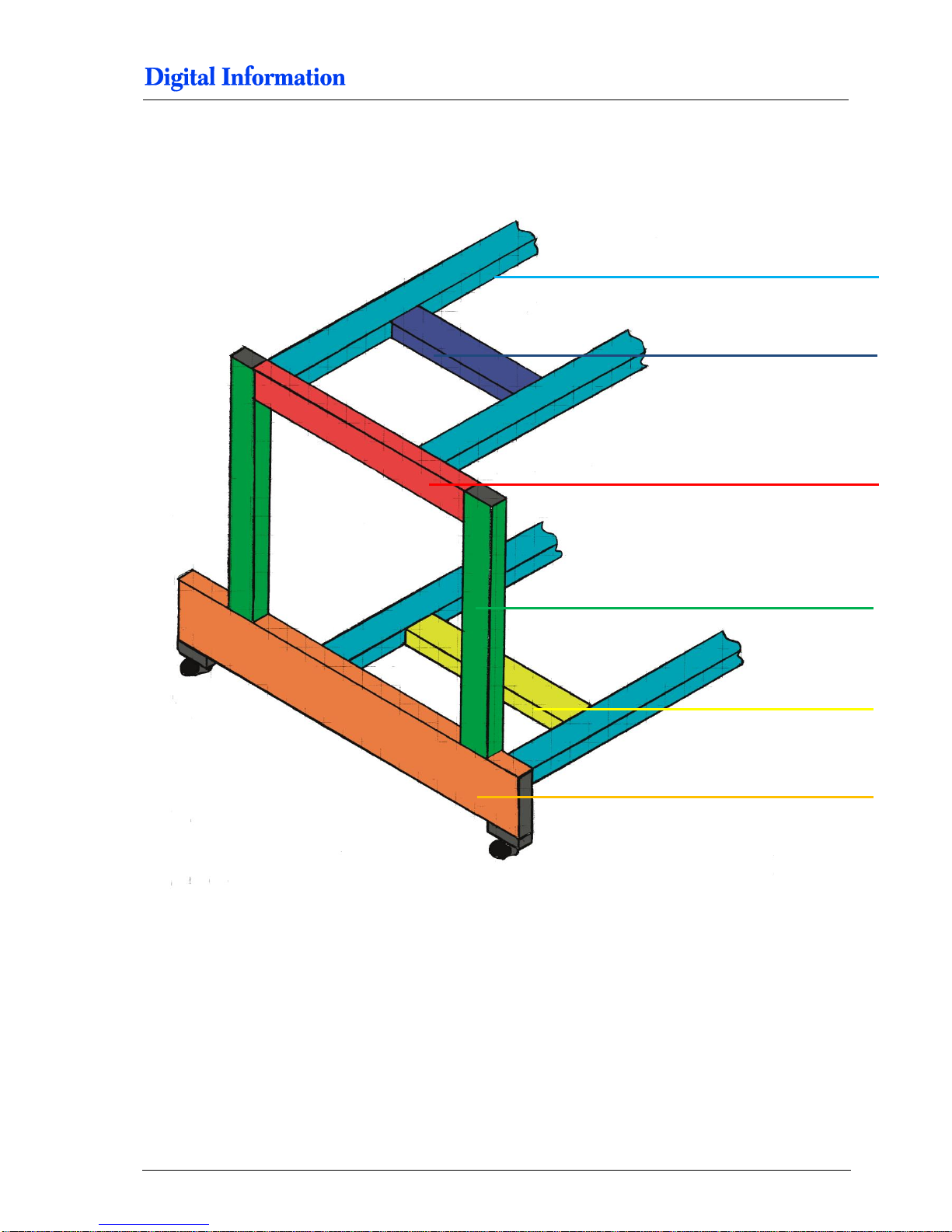
4.3 DJet 300 Setup
Pos 6 – 1310 mm
Pos 1 – 1100 mm
Pos 3 – 385 mm
Pos 4 – 545 mm
Pos 2 – 675 mm
Pos 5 – 650 mm
Pos 2 – 675 mm
Page 16
4
Frame Setup
Frame Parts
4-4 DJet 300-500-700 – HW Installation Manual
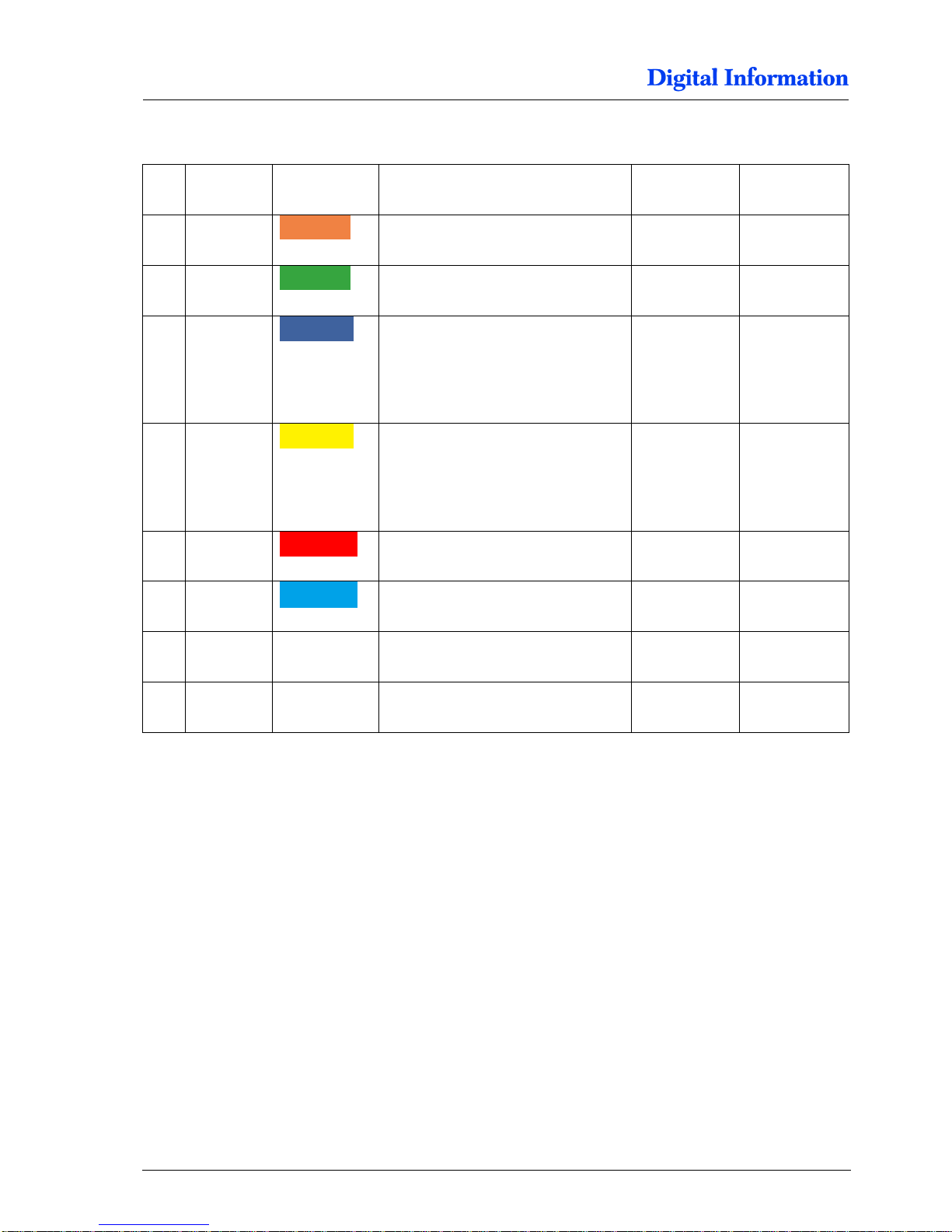
4.4 Frame Parts
Pos Amount
Color
Name
Profile in mm
Length in mm
1 2 Cross-member, 2 wheels mounted
40 x 160
1100
2
4 Pillar
40 x 80
675
3
2 Distance holder for top crossmembers, position 6.
Used to mount the Epson printer to
the stand
40 x 80
385
4
2
Distance holder for bottom crossmembers, position 6.
Used to mount the Epson printer to
the stand
40 x 80
545
5 2 Cross-member top
40 x 80
650
6 4 Cross-member for printer top /
bottom
40 x 80
1310
7 4 Base plate for swivel caster
40 x 80
8 4
Swivel caster, 75mm
Page 17
Frame Assembly
Base Plates
5
DJet 300-500-700 – HW Installation Manual 5-1
5 Frame Assembly
5.1 Base Plates
5.1.1 Parts
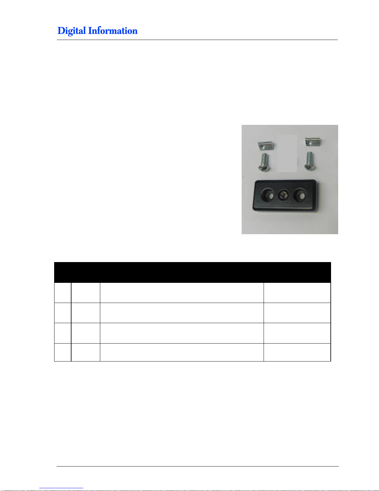
Locate the following parts.
Pos Amount
Name
Dimension
23
4 Base plate for swivel caster with M10
40 x 80
25
8 Allen screw with rounded head,
M8 x 20
26
8 Slot nut
M8
1 2 Aluminum Profile Nr.1
1100 mm
Page 18
5
Frame Assembly
Base Plates
5-2 DJet 300-500-700 – HW Installation Manual
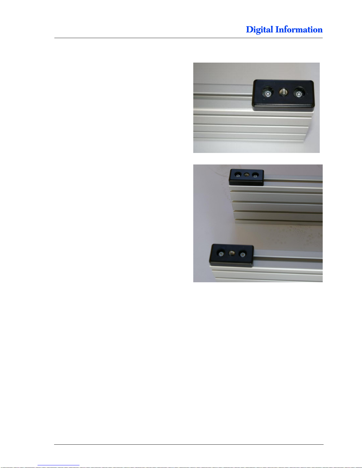
5.1.2 Assembly
Mount on both sides of profile Nr.1 (orange - 1100
mm) the wheel base plates.
Page 19
Frame Assembly
Side Frame
5
DJet 300-500-700 – HW Installation Manual 5-3
5.2 Side Frame
5.2.1 Parts
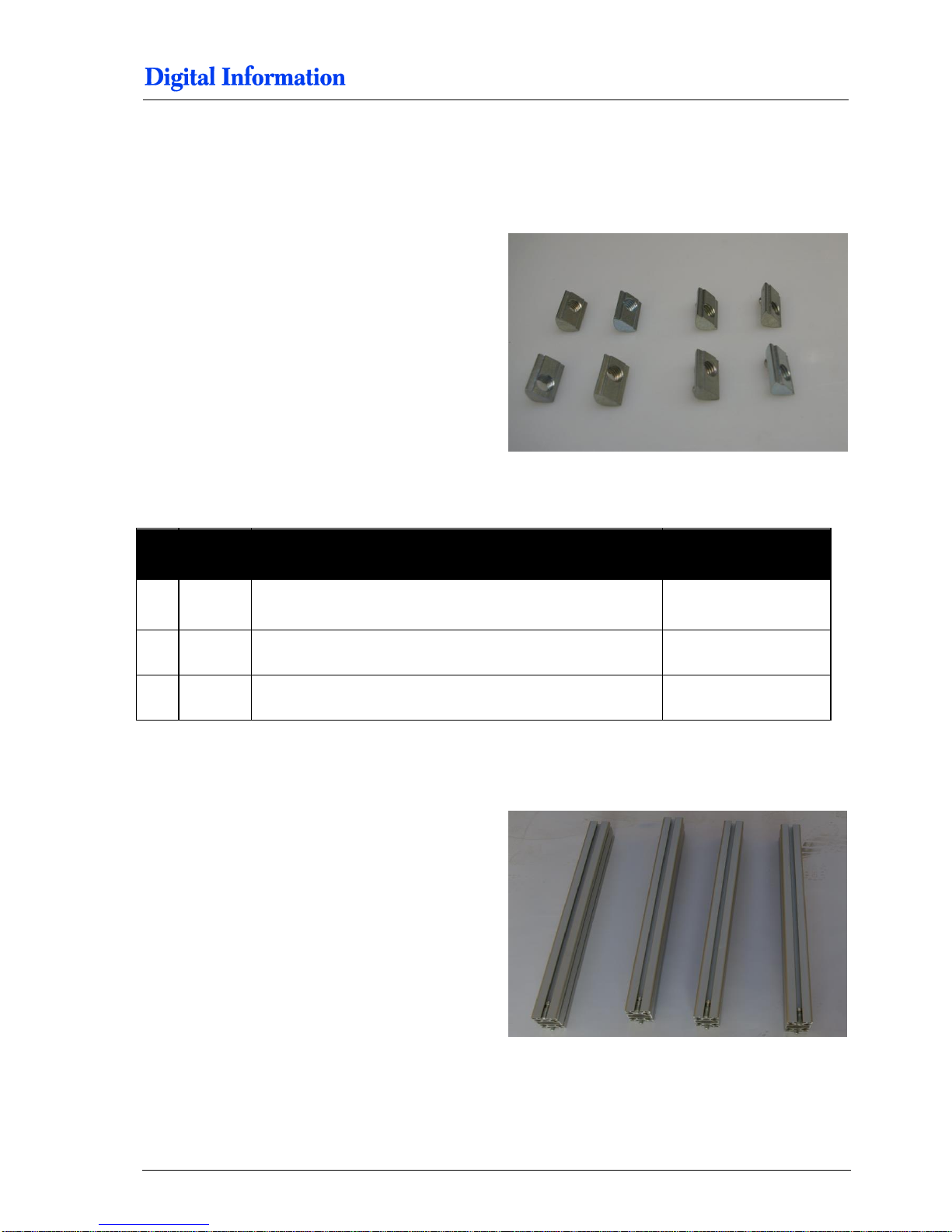
Locate the following parts.
5.2.2 Assembly
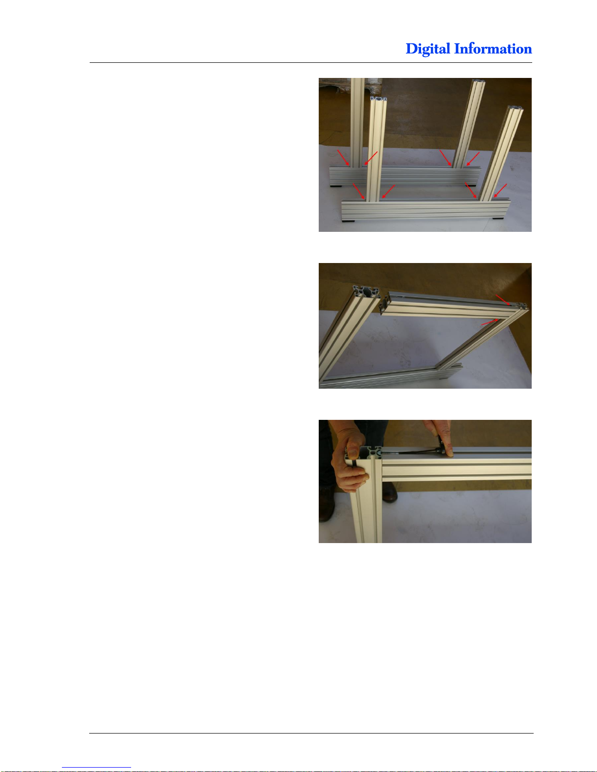
Locate profile Nr.2 (green - 675 mm).
Pos Amount
Name
Dimension
26
16 Slot nut
M8
2 4 Aluminum Profile Nr.2
675 mm
5 2 Aluminum Profile Nr.5
650 mm
Page 20
5
Frame Assembly
Side Frame
5-4 DJet 300-500-700 – HW Installation Manual
Frist, insert 4 slot nuts M8 into each base profile
Nr.1. Then mount profile Nr.2.
Do not fully tighten the screws yet!
Locate profile Nr.5 (red – 650 mm).
Insert into profile Nr.2 four slot nuts, size M8.
Tighten the screws firmly on the right sides.
Tighten the screws firmly on the left side.
Page 21
Frame Assembly
Cross-Beam Profile
5
DJet 300-500-700 – HW Installation Manual 5-5
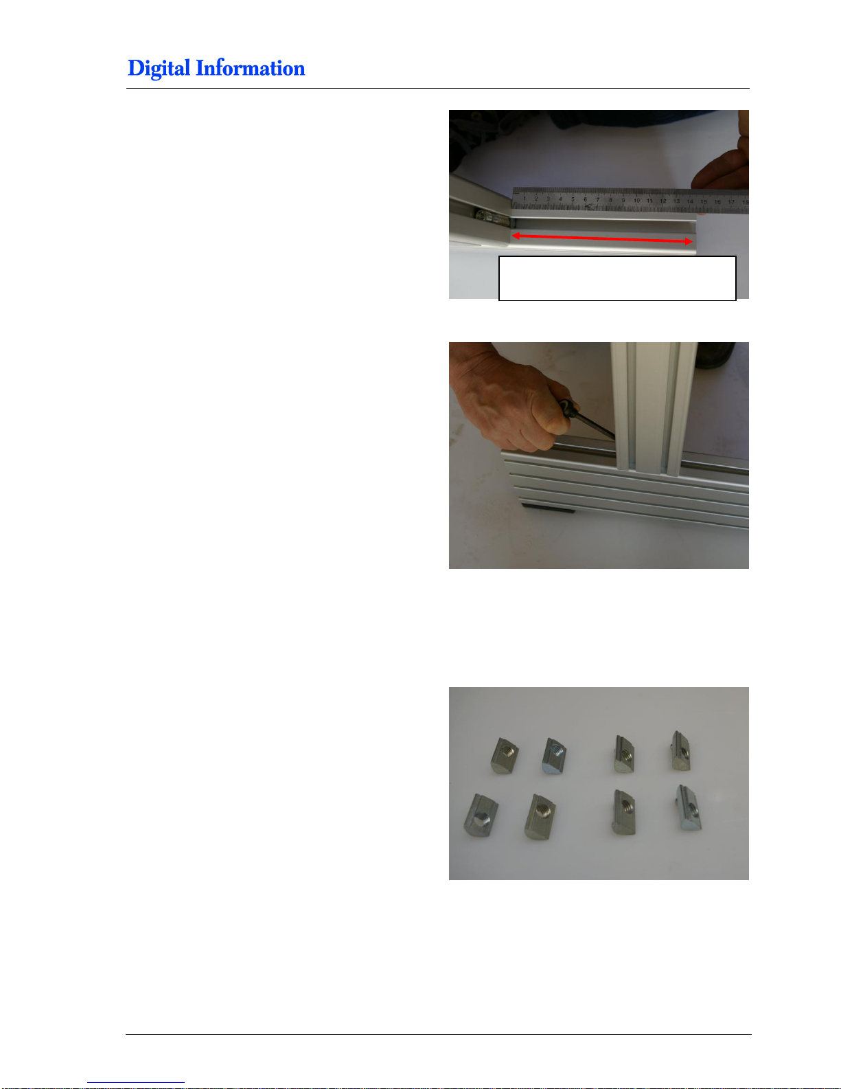
Adjust profile Nr.2 at 145 mm from the profile edge.
Tighten all screws firmly.
5.3 Cross-Beam Profile
5.3.1 Parts
Locate the following parts.
distance between pillar and edge is
145 mm
Page 22
5
Frame Assembly
Cross-Beam Profile
5-6 DJet 300-500-700 – HW Installation Manual
5.3.2 Assembly
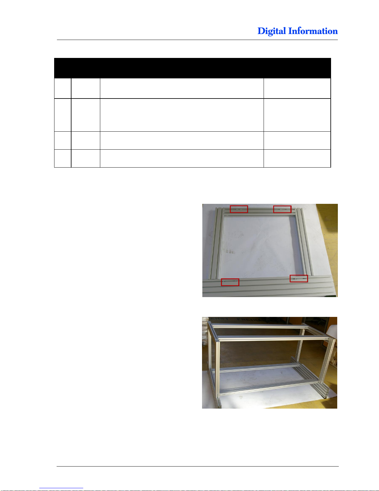
Insert eight slot nuts M8 into each “side frame” as
shown.
Mount profiles Nr.6.
Do not fully tighten the screws yet!
Pos Amount
Name
Dimension
26
8 Slot nut
M8
6 4 Aluminium Profile Nr.6
T7000 = 1780 mm
T5000 = 1780 mm
T3000 = 1310 mm
3 2 Aluminium Profile Nr.3
385 mm
2 2 Aluminium Profile Nr.2
545 mm
Page 23
Frame Assembly
Cross-Beam Profile
5
DJet 300-500-700 – HW Installation Manual 5-7
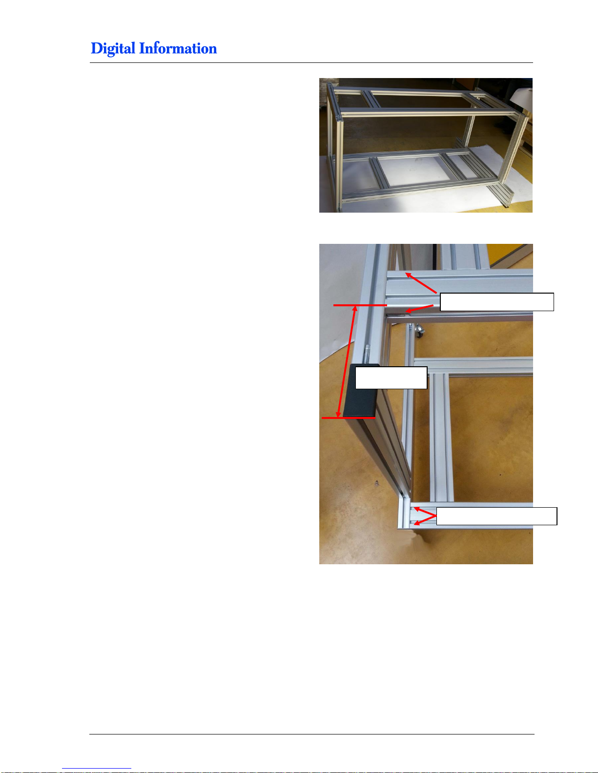
Mount profile Nr.3 (blue - 385 mm) and Nr.4 (yellow
- 545 mm) between the cross beam profiles.
Do not fully tighten the screws yet!
Line up the top and bottom cross beam profile as
shown in the picture.
Tighten the screws on both sides of the cross beam
profile firmly.
185 mm
tighten this profile firmly
tighten this profile firmly
Page 24
5
Frame Assembly
Cross-Beam Profile
5-8 DJet 300-500-700 – HW Installation Manual
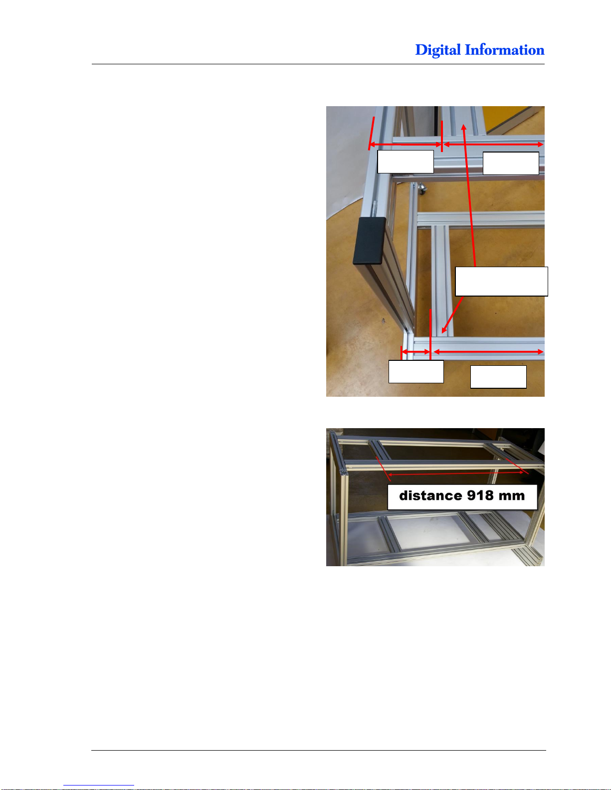
5.3.3 Measurements for DJet 300 / 23“ Version
First, line up the top cross section profile from the
left side as shown in the picture.
Tighten it firmly.
Then, position the second cross-profile as shown
(918 mm from left side to left side of the profile).
Tighten it firmly.
200 mm
116 mm
tighten firmly only
on this side
918 mm
918 mm
Page 25
Frame Assembly
Cross-Beam Profile
5
DJet 300-500-700 – HW Installation Manual 5-9
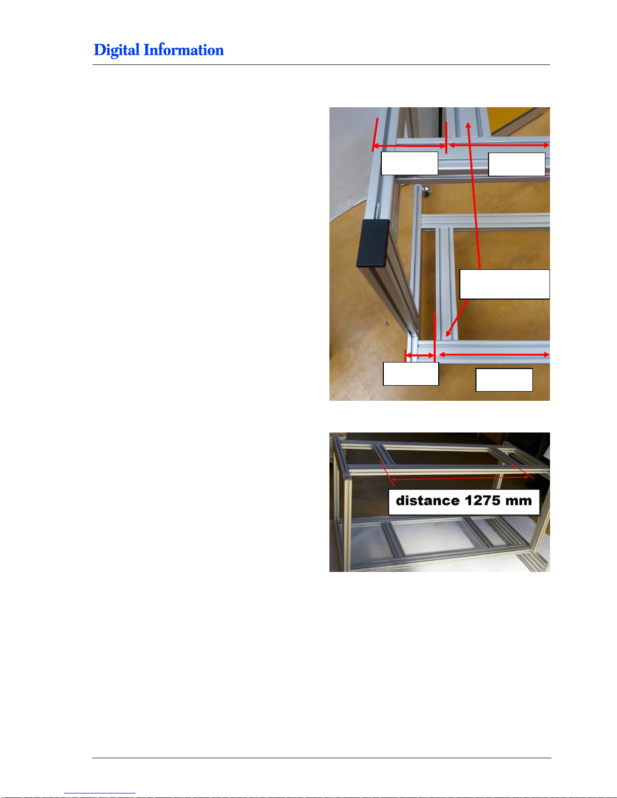
5.3.4 Measurements for DJet 500 / 35“ Version
First, line up the top cross section profile from the
left side as shown in the picture.
Tighten it firmly.
Then, position the second cross-profile as shown
(1275 mm from left side to left side of the profile).
Tighten it firmly.
229 mm
195 mm
tighten firmly only
on this side
1275 mm
1275 mm
Page 26
5
Frame Assembly
Cross-Beam Profile
5-10 DJet 300-500-700 – HW Installation Manual
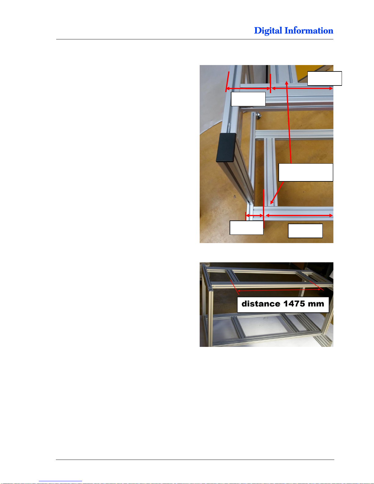
5.3.5 Measurements for DJet 700 / 43“ Version
First, line up the top cross section profile from the
left side as shown in the picture.
Tighten it firmly.
Then, position the second cross-profile as shown in
picture.
Note
The measurement 1475 mm is taken from the left
side of the first cross-profile to the left side of the
second cross-profile.
Tighten it firmly.
129 mm
95 mm
tighten firmly only
on this side
1475 mm
1475 mm
Page 27
Frame Assembly
Wheels
5
DJet 300-500-700 – HW Installation Manual 5-11
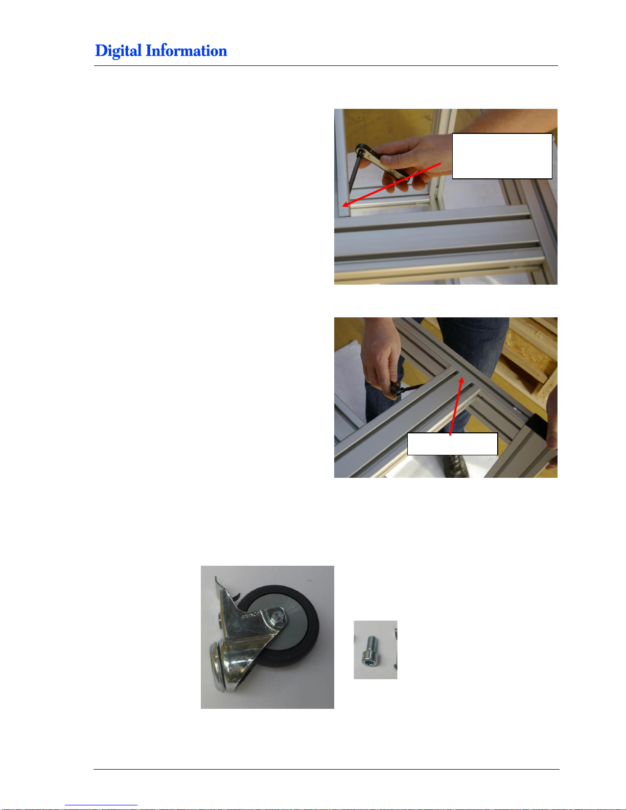
5.3.6 Tighten all Profiles
First, tighten firmly the short cross beam-profile on
top and bottom.
Then, tighten firmly the cross beam-profiles to the
side frames.
5.4 Wheels
5.4.1 Parts
tighten firmly the
short cross beam
profile
tighten firmly
Page 28
5
Frame Assembly
Printer Base Plates
5-12 DJet 300-500-700 – HW Installation Manual
5.4.2 Mount the Wheels
On each side frame, mount the wheels to the base plates.
5.5 Printer Base Plates
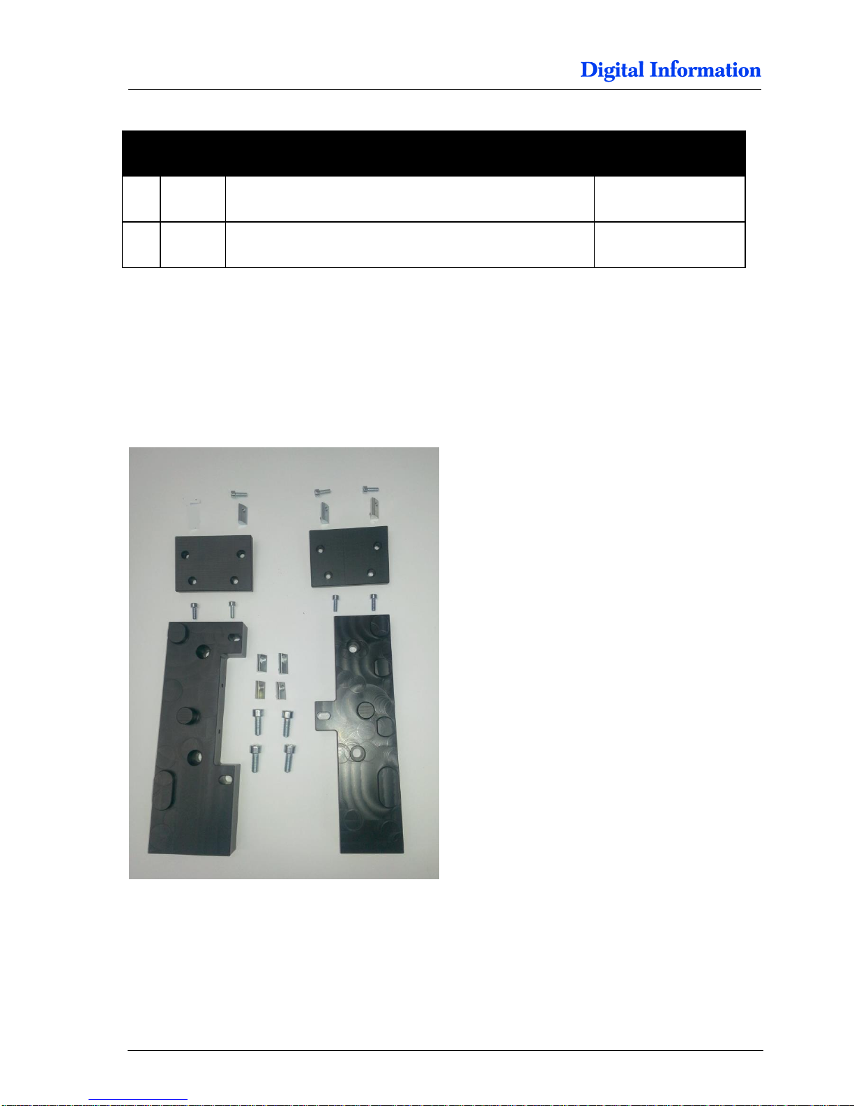
5.5.1 Parts for each Printer
Pos Amount
Name
Dimension in mm
22 4
Swivel caster with break
Wheel diameter = 75
24
4 Cylinder head screw with hexagonal
Fixes swivel caster to base plate
M10 x 20
Page 29
Frame Assembly
Printer Base Plates
5
DJet 300-500-700 – HW Installation Manual 5-13
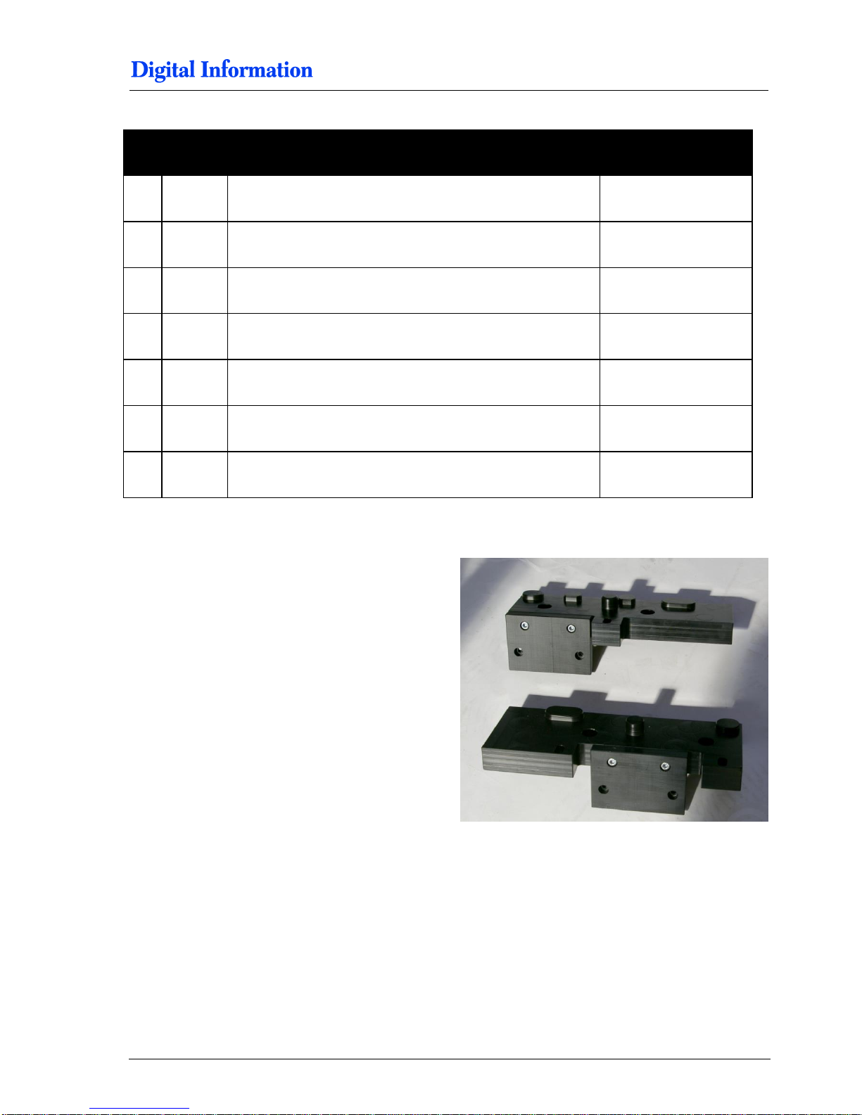
5.5.2 Assembly POM Parts
Bolt the mounting plate to the base plate as shown.
Use the M5 x 14 screws.
Pos Amount
Name
Dimension in mm
1 POM part - Base plate left
1 POM part - Base plate right
2
POM part - Mounting plate
28
4 Cylinder head screw with hexagonal
M8 x 20
29
7 Cylinder head screw with hexagonal
M5 x 14
30
4 Slot nut
M8
31 3 Slot nut
M5 (full size slot nut)
Page 30
5
Frame Assembly
Printer Base Plates
5-14 DJet 300-500-700 – HW Installation Manual
5.5.3 Base Plates for Top Printer
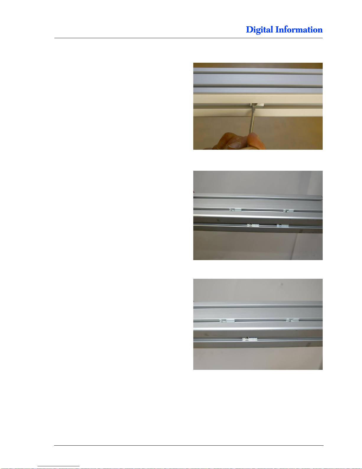
Insert one slot nuts M5 into the inner side of the
right cross section profiles.
Insert two slot nuts M5 into the inner side of the left
cross section profiles.
Note
Use only the full size M5 slot nuts, never the half
size.
Insert two slot nuts M8 into the upper side of the
cross section profile (top left cross section profile)
Insert two slot nuts M8 into the upper side of the
cross section profile (top right cross section profile)
Page 31
Frame Assembly
Printer Base Plates
5
DJet 300-500-700 – HW Installation Manual 5-15
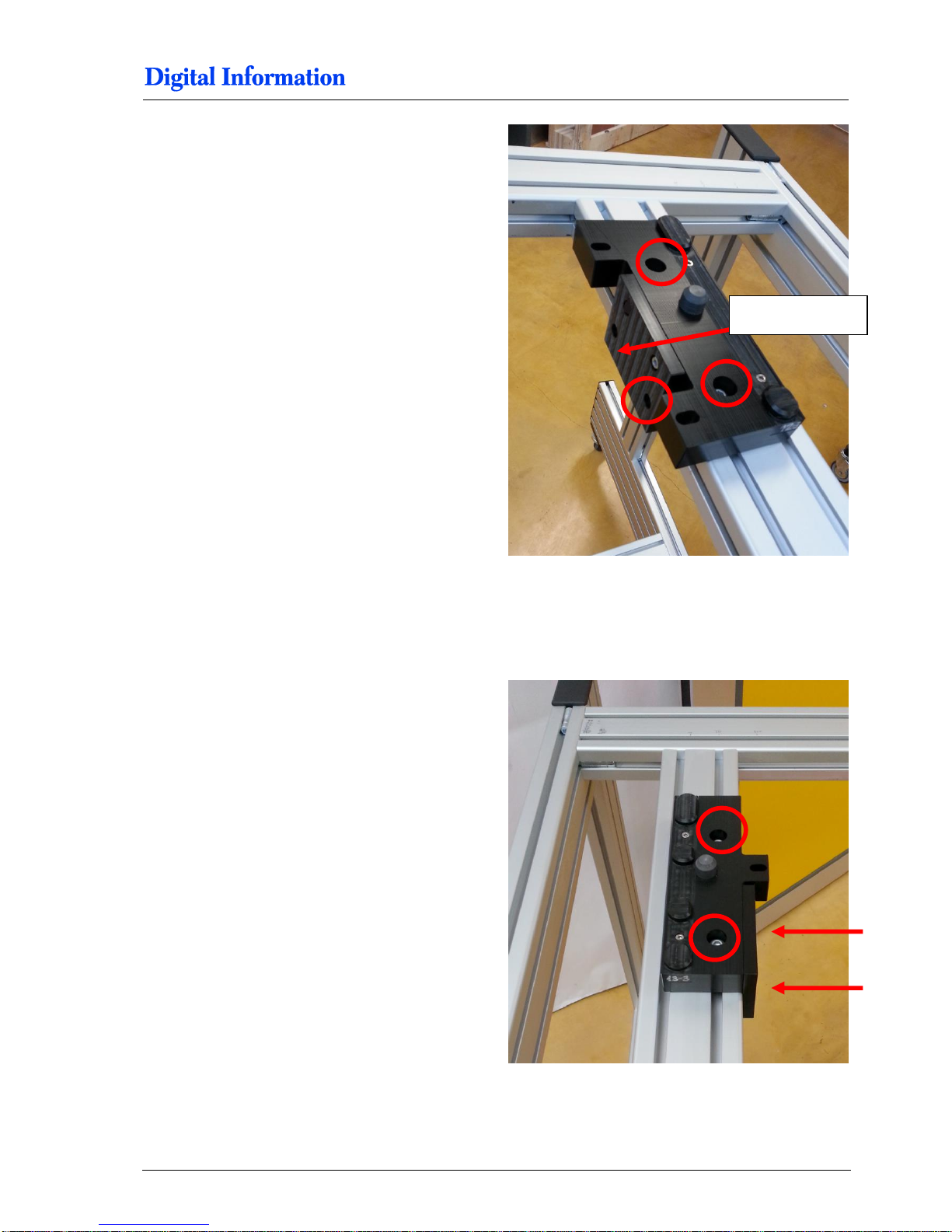
Mount the base plate which has two holes to the
right cross section profile.
Use only one M5 x 14 on the side and two M8 x 20
on the top.
Do not fully tighten the screws yet! The base plates
should be movable.
Mount the base plate which has one hole to the left
cross section profile.
Use two M5 x 14 and two M8 x 20.
Do not fully tighten the screws yet! The base plates
should be movable.
set no screw here
Page 32
5
Frame Assembly
Printer Base Plates
5-16 DJet 300-500-700 – HW Installation Manual
5.5.4 Position the Base Plates Front Printer
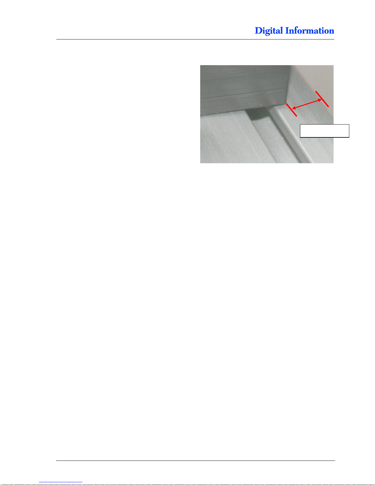
Position the base plates that the distance between
the profile edge and the printer support plate is
approx. 12 mm.
Tighten all screws from the support plate and tight
the screws from the chapter before.
5.5.5 Base Plates for Bottom Printer
Do the same for the bottom printer but mount the base plates the other way around.
approx 12 mm
Page 33
Prepare BACK Printer
Paper Roll Holder Guide Epson
6
DJet 300-500-700 – HW Installation Manual 6-1
6 Prepare BACK Printer
6.1 Paper Roll Holder Guide Epson
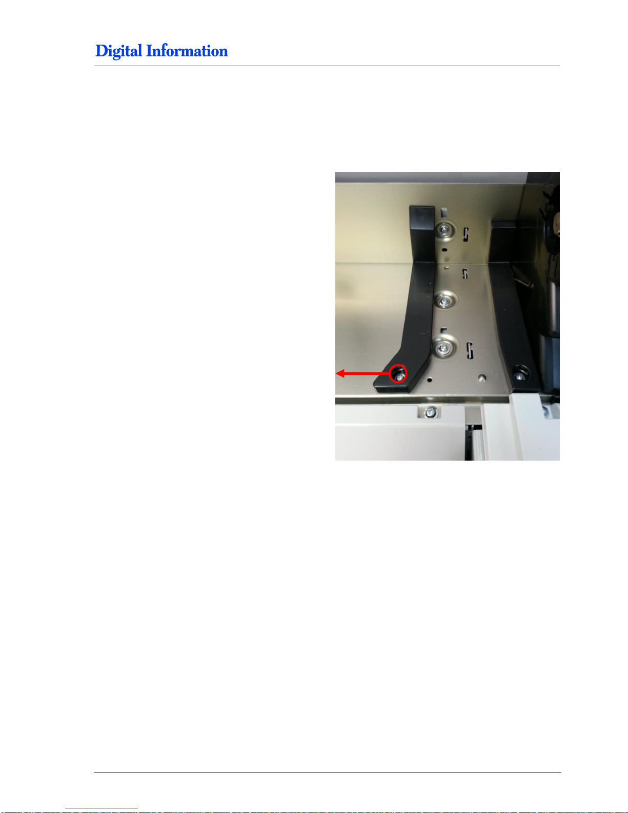
To remove the roll holder guide, take first this screw
off here.
Page 34
6
Prepare BACK Printer
Paper Roll Holder Guide Epson
6-2 DJet 300-500-700 – HW Installation Manual
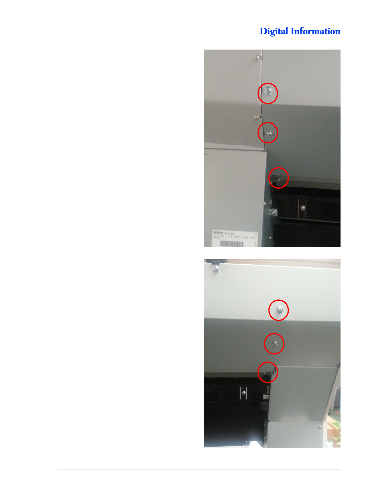
On the left side of the printer, take this 3 screws off.
On the right side take this 3 screws off.
Page 35
Prepare BACK Printer
Paper Roll Holder Guide Epson
6
DJet 300-500-700 – HW Installation Manual 6-3
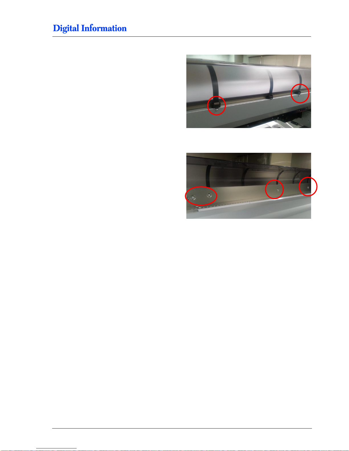
On the back side take off this screws here.
On the inside take off this screws here.
Now bend the back cover on the right side a bit
backward to access the screw which mounts the
paper roll holder guide.
Take off the screw and remove the guide. Remount
all screws.
Page 36
6
Prepare BACK Printer
Base Profile for Paper Guide and Camera Holder
6-4 DJet 300-500-700 – HW Installation Manual
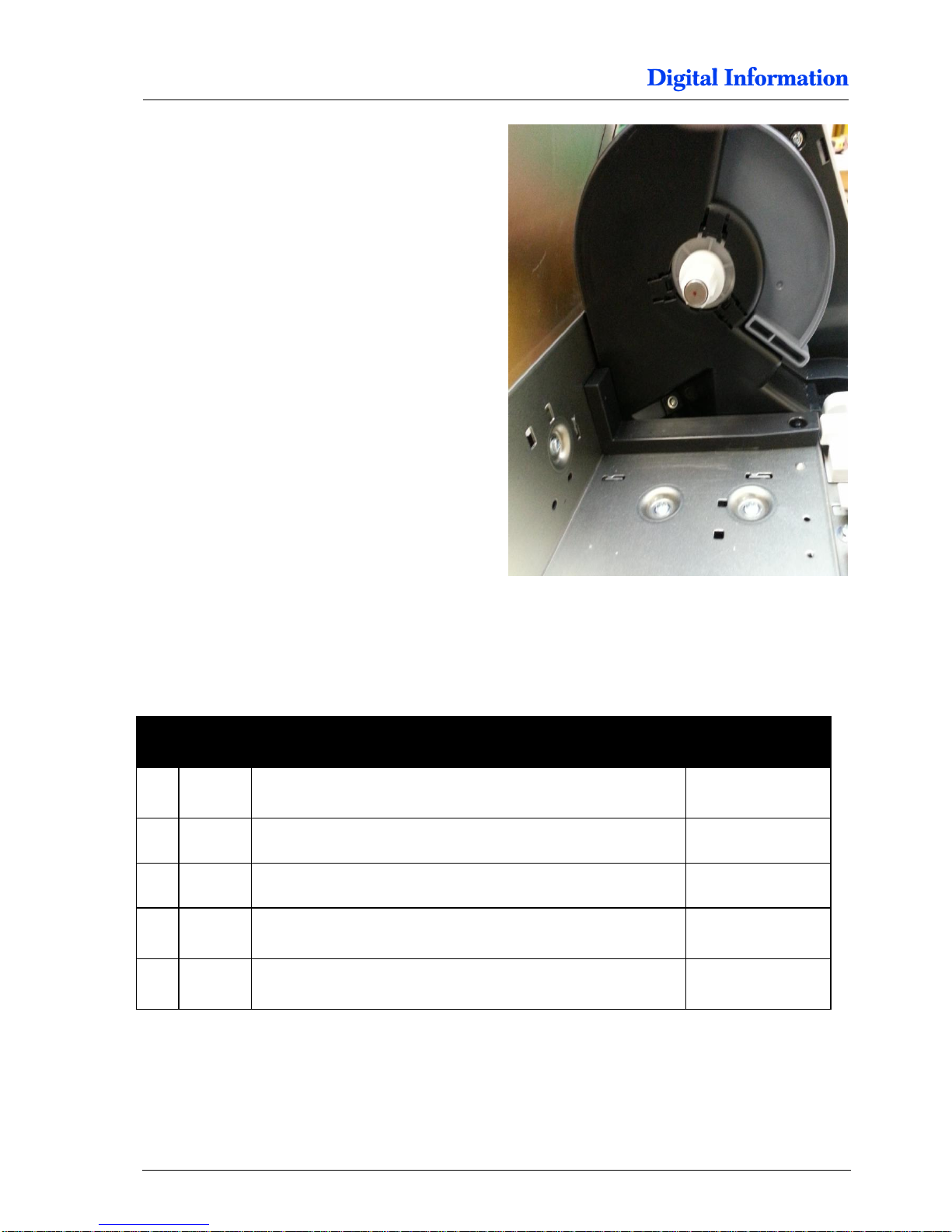
Printer looks like shown.
6.2 Base Profile for Paper Guide and Camera Holder
6.2.1 Additional Parts
Pos Amount
Name
Dimension in mm
51 1
Profile for Printer Bottom „for camera and paper feed holder“
15 x 40 x 1260
T7000
51 1 Profile for Printer Bottom „for camera and paper feed holder“
15 x 40 x 1020
T5000
51 1 Profile for Printer Bottom „for camera and paper feed holder“
15 x 40 x 705
T3000
52 2 Cylinder head screw with hexagonal
M4 x 25
2 POM Part
Page 37
Prepare BACK Printer
Base Profile for Paper Guide and Camera Holder
6
DJet 300-500-700 – HW Installation Manual 6-5
6.2.2 Assembly
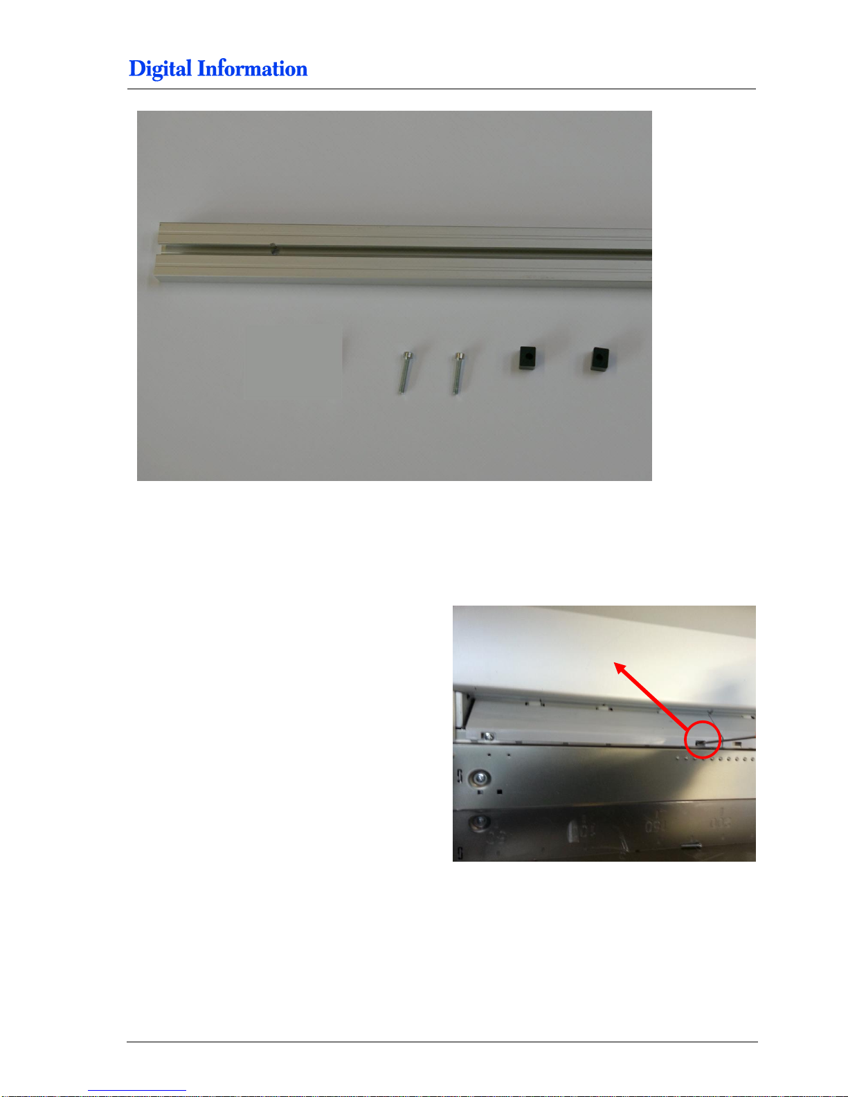
Remove the screw here.
Page 38
6
Prepare BACK Printer
Base Profile for Paper Guide and Camera Holder
6-6 DJet 300-500-700 – HW Installation Manual
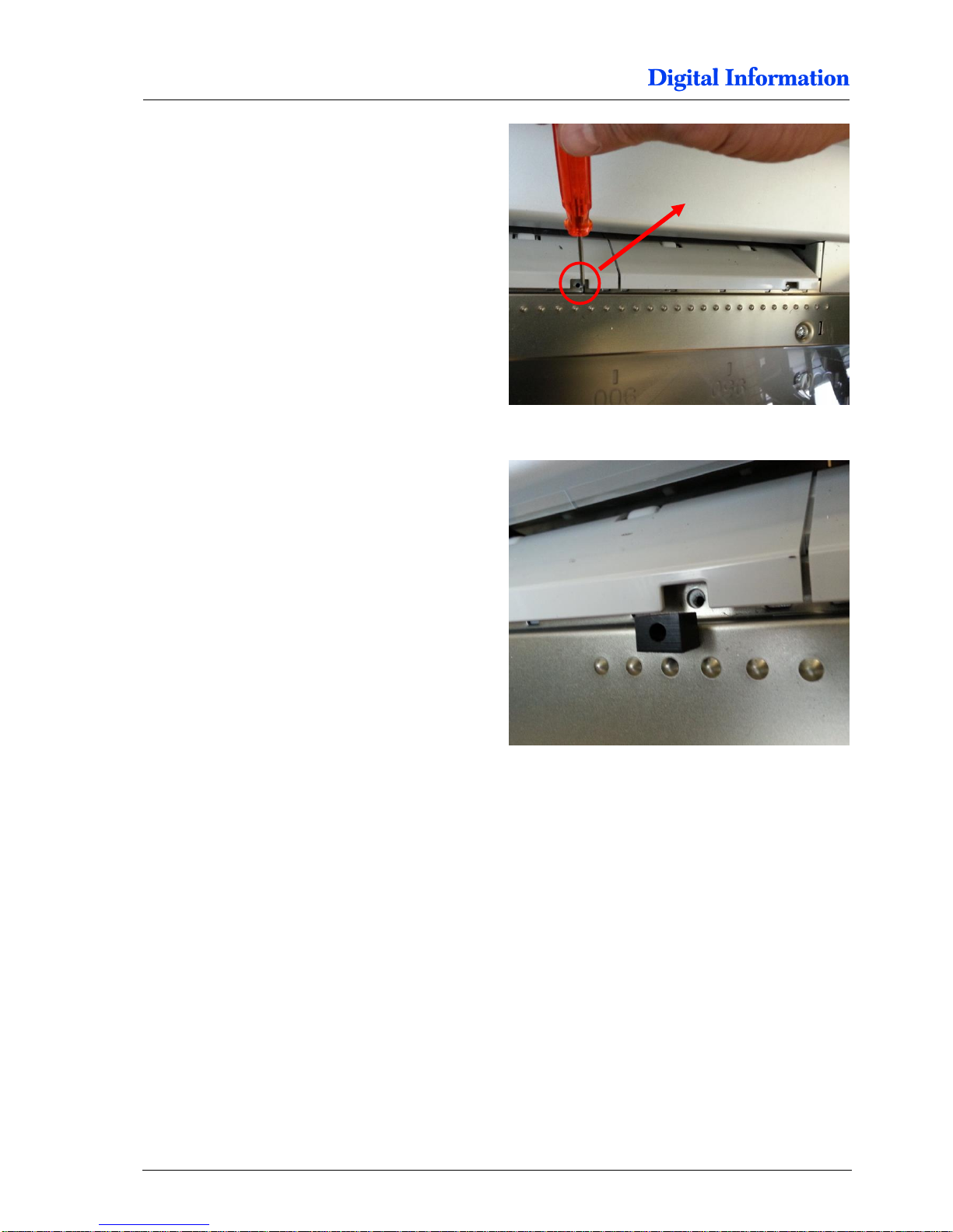
Remove the screw here.
Place the POM part into the aperture.
Page 39
Prepare BACK Printer
Base Profile for Paper Guide and Camera Holder
6
DJet 300-500-700 – HW Installation Manual 6-7
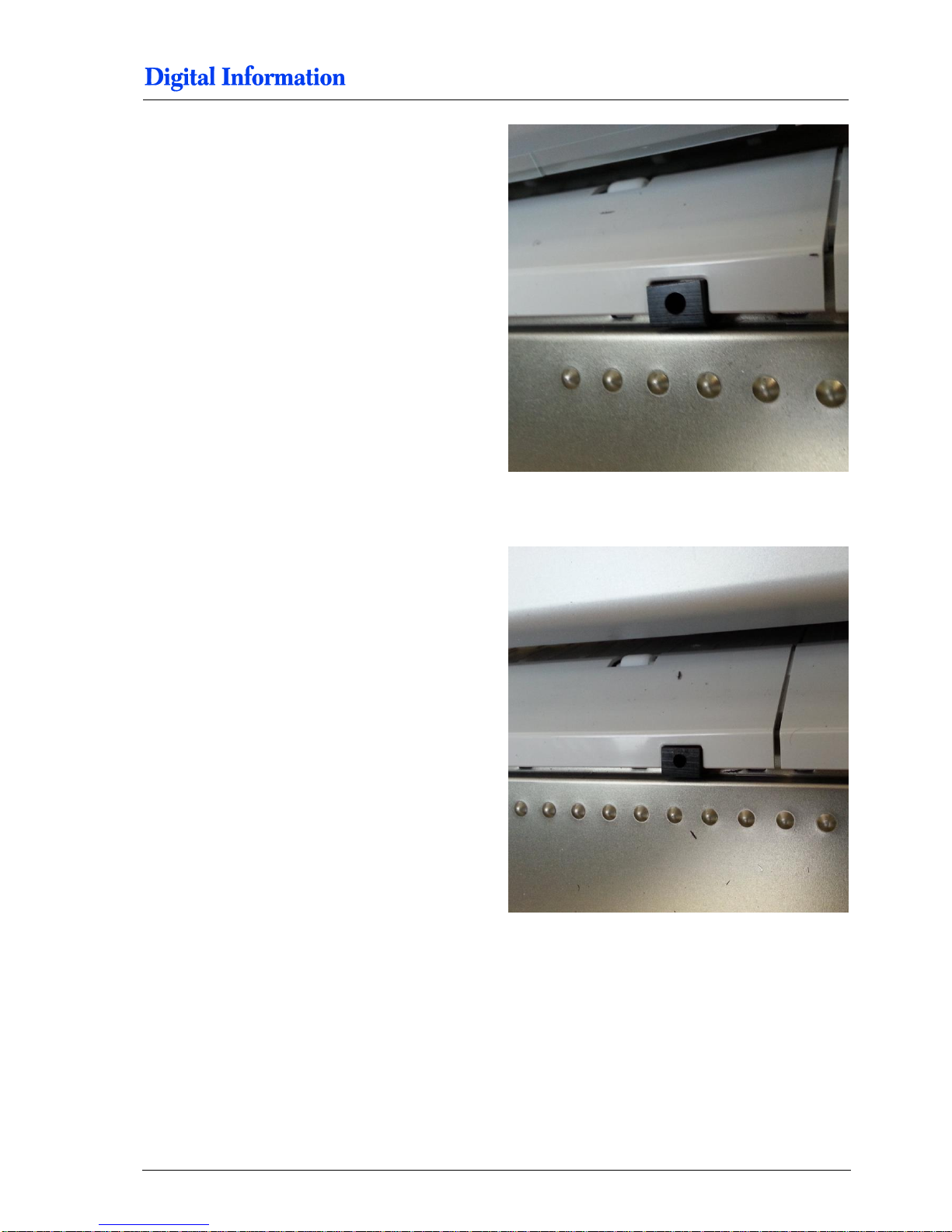
Put the POM part into the aperture as shown.
Do the same with the second aperture.
Page 40
6
Prepare BACK Printer
Base Profile for Paper Guide and Camera Holder
6-8 DJet 300-500-700 – HW Installation Manual
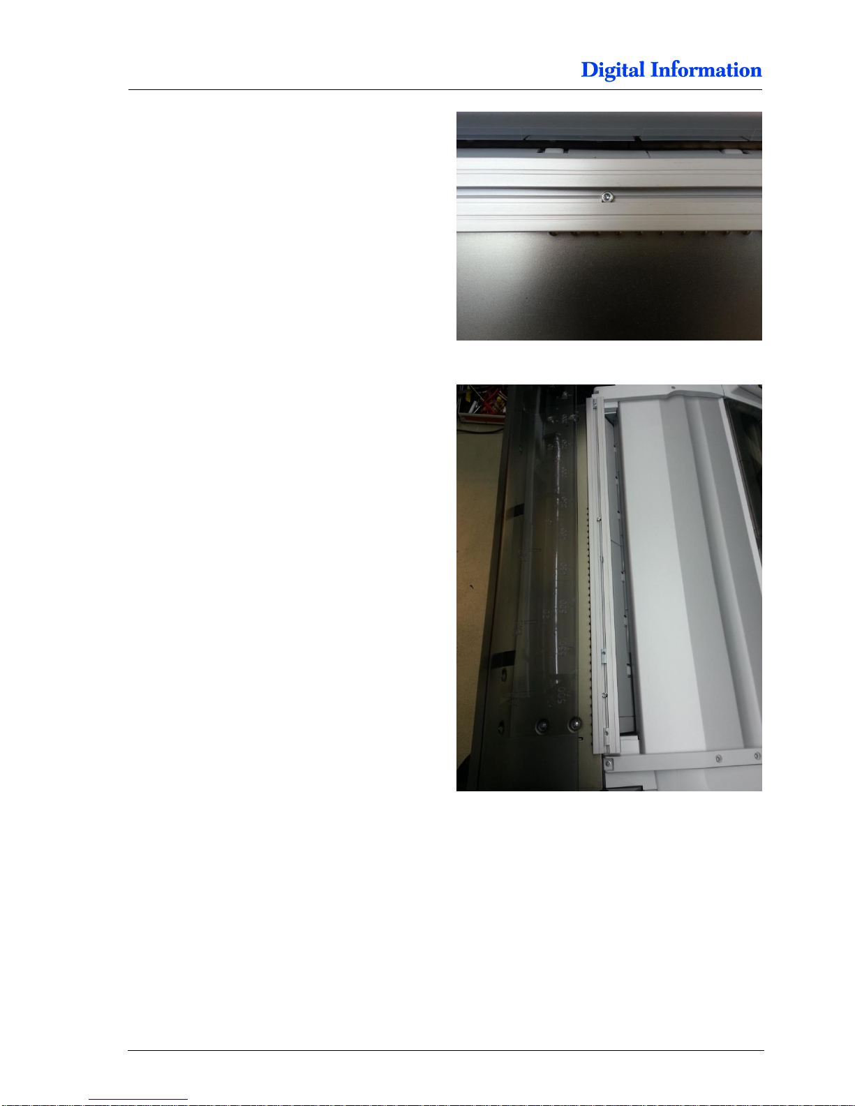
Use the M4 x25 screws to mount the profile to the
printer.
Do not fully tighten the screws yet!
Do not fully tighten the screws yet!
Page 41
Prepare BACK Printer
Base Profile for Paper Guide and Camera Holder
6
DJet 300-500-700 – HW Installation Manual 6-9
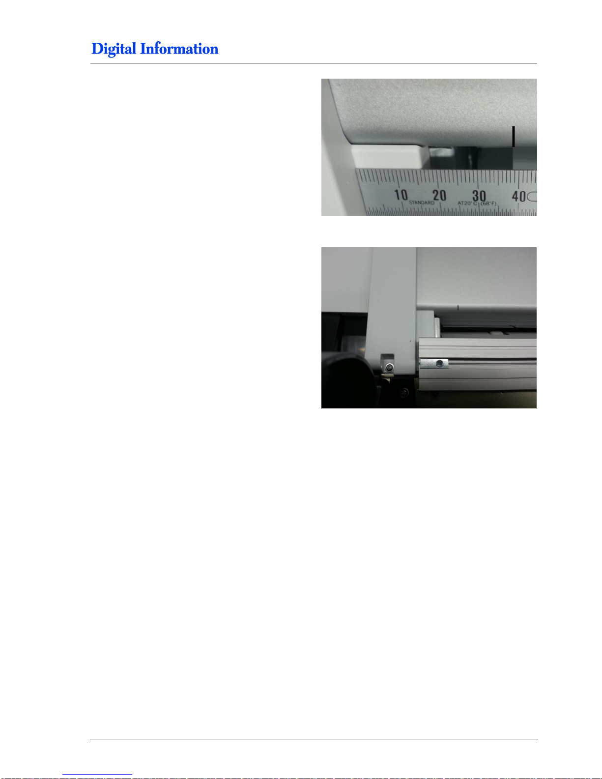
On the left side of the back printer, mark the paper
entry at 39mm.
Overview.
Page 42
7
Paper Entry Guide / Camera System
Side parts - Step 1
6-10 DJet 300-500-700 – HW Installation Manual
7 Paper Entry Guide / Camera System
7.1 Side parts - Step 1
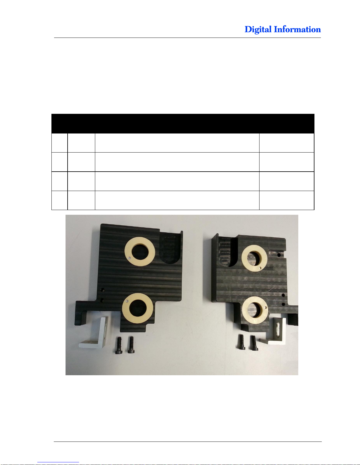
7.1.1 Parts
Pos Amount
Name
Dimension in mm
03 1
Side holder, left
04 1 Side holder, right
56 2 Aluminum Bracket
25 x 35
57 4 Cylinder head screw with hexagonal
M5 x 16
Page 43
Paper Entry Guide / Camera System
Side Parts - Camera Holder BACK Printer
7
DJet 300-500-700 – HW Installation Manual 6-11
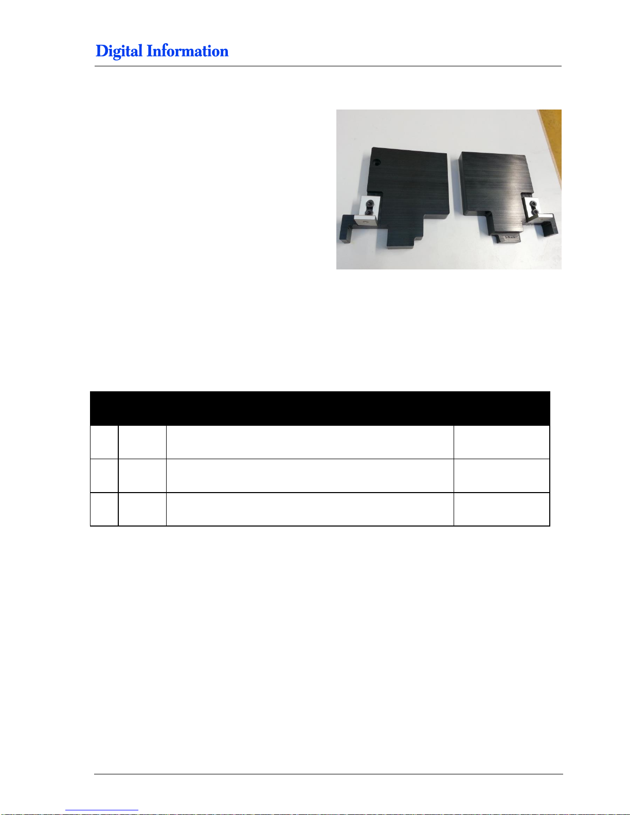
7.1.2 Assembly
Mount the brackets to the “side holders” as shown.
7.2 Side Parts - Camera Holder BACK Printer
7.2.1 Parts
Pos Amount
Name
Dimension in mm
06 1
Camera holder BACK printer
07 1 Camera holder
58 2 Cylinder head screw with hexagonal
M5 x 10
Page 44
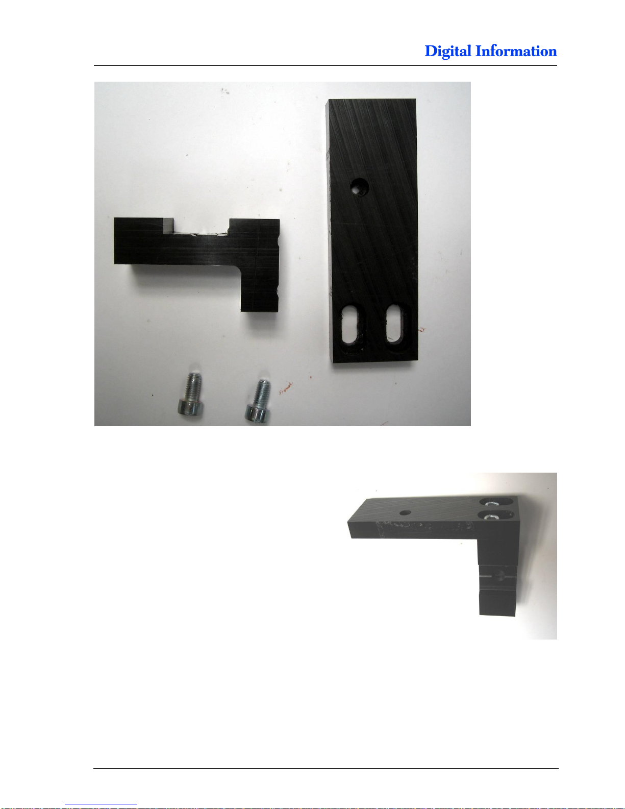
7
Paper Entry Guide / Camera System
Side Parts - Camera Holder BACK Printer
6-12 DJet 300-500-700 – HW Installation Manual
7.2.2 Assembly
Mount the camera parts as shown.
Page 45
Paper Entry Guide / Camera System
Assembly „Right Holder“ and „Camera holder“
7
DJet 300-500-700 – HW Installation Manual 6-13
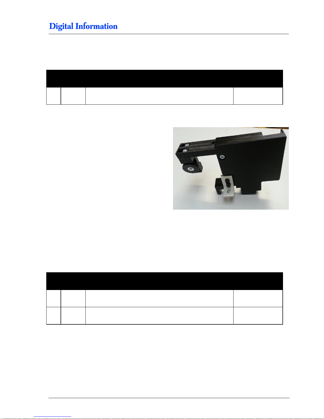
7.3 Assembly „Right Holder“ and „Camera holder“
7.3.1 Parts
Pos Amount
Name
Dimension in mm
59 1 Cylinder head screw with hexagonal
M5 x 20
7.3.2 Assembly
Assemble the two parts like shown.
7.4 Paper Guide Entry to BACK printer
7.4.1 Parts
Pos Amount
Name
Dimension in mm
62 2
Cylinder head screw with hexagonal
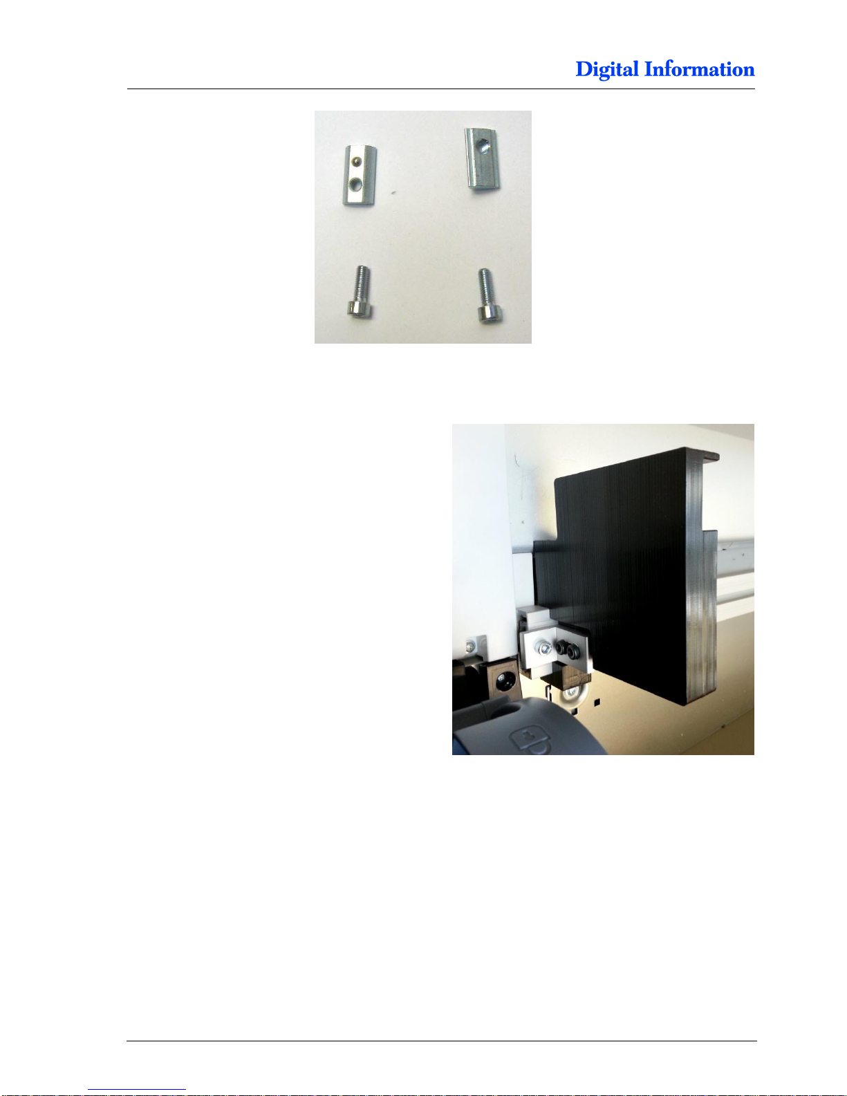
M5 x 14
63 2 Slot nut (half size)
M5
Page 46
7
Paper Entry Guide / Camera System
Paper Guide Entry to BACK printer
6-14 DJet 300-500-700 – HW Installation Manual
7.4.2 Side Holders to Base Profile
Add the slot nut M5 into 15x40 profile and mount the
left side holder to it.
Do not fully tighten the screw yet!
Page 47
Paper Entry Guide / Camera System
Paper Guide Roller
7
DJet 300-500-700 – HW Installation Manual 6-15
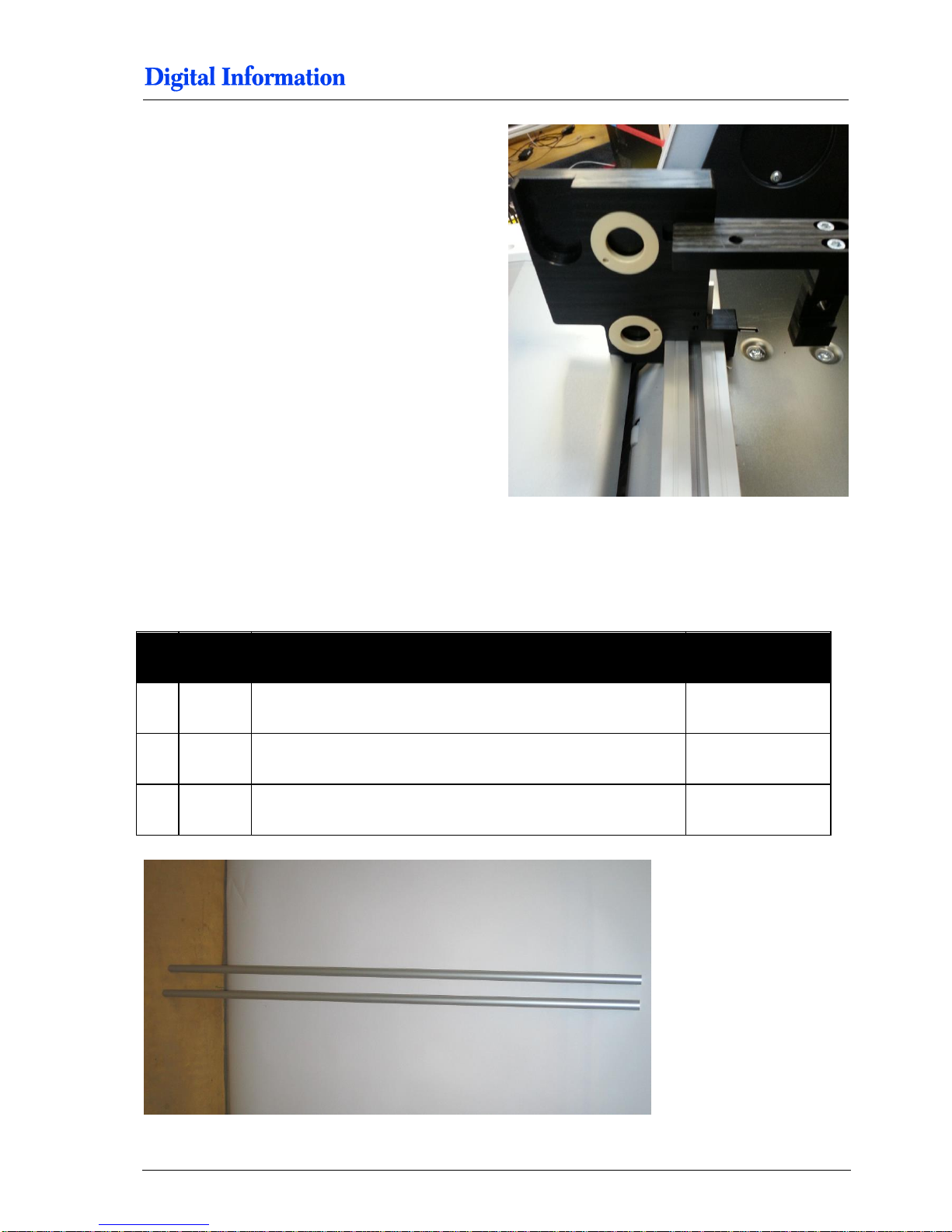
Add the slot nut M5 into 15x40 profile and mount the
right side holder to it.
Do not fully tighten the screw yet!
7.5 Paper Guide Roller
7.5.1 Parts
Pos Amount
Name
Dimension in mm
64 2
Aluminum roller, 20mm diameter
1144
for T7000
64 2
Aluminum roller, 20mm diameter
941
for T5000
64 2
Aluminum roller, 20mm diameter
641
for T3000
Page 48
7
Paper Entry Guide / Camera System
Paper Guide Roller
6-16 DJet 300-500-700 – HW Installation Manual
7.5.2 Paper Guide Roller
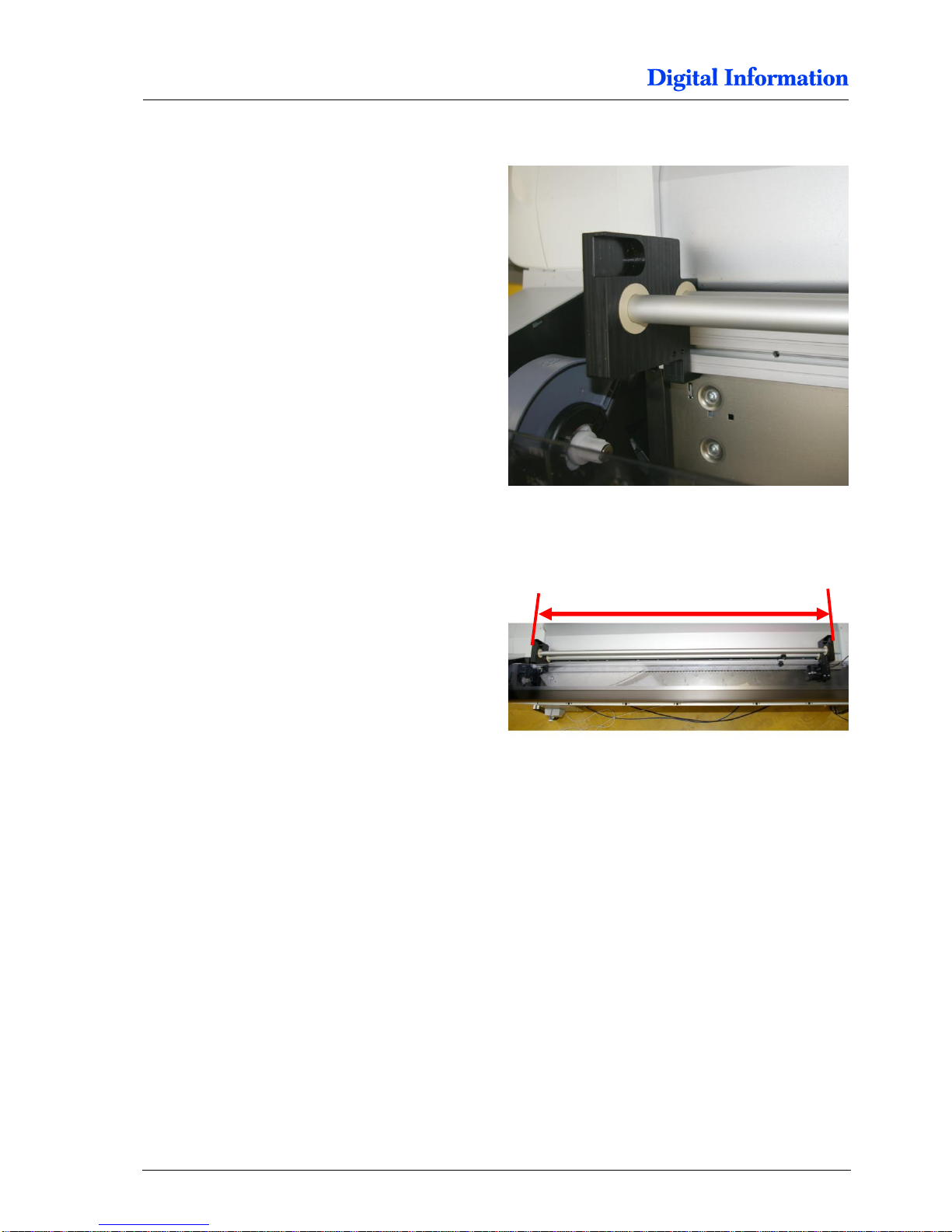
Mount the two rollers into the side holders-
First, tighten firmly the left “side holder” to the base
profile. Position it at the end of the profile.
Then adjust the width of the right “side holder”
T7000 1173 mm
T5000 970 mm
T3000 670 mm
T7000 = 1173 mm
T5000 = 970 mm
T3000 = 670 mm
Page 49
Paper Entry Guide / Camera System
Angled Paper Bracket for Printer Back
7
DJet 300-500-700 – HW Installation Manual 6-17
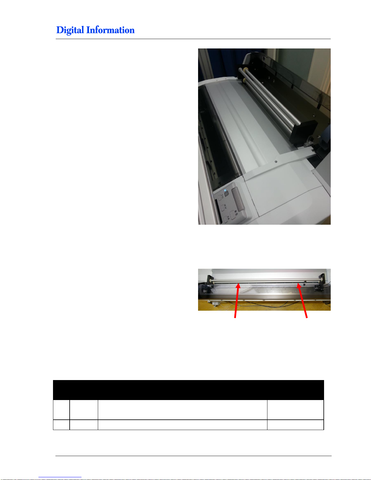
Add the tension roller and verify whether all three
rollers can rotate smoothly.
Finally, tight firmly the two M4 screws to mount the
“paper entry guide” to the printer.
7.6 Angled Paper Bracket for Printer Back
7.6.1 Parts
Pos Amount
Name
Dimension in mm
62 1
Finger Screw
M5 x 13
63 1 Slot Nut (half size)
M5
tight the M4 screws
Page 50
7
Paper Entry Guide / Camera System
Angled Paper Bracket for Printer Back
6-18 DJet 300-500-700 – HW Installation Manual
1
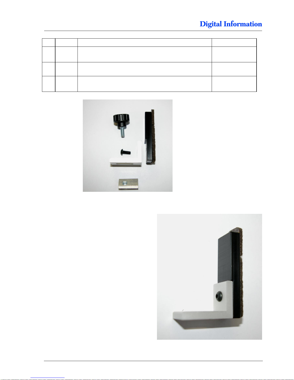
Pom part
1 Round-head screw
M4 x 10
56 1 Aluminum Bracket
25 x 35
7.6.2 Assembly
Mount the bracket with the M4 screw to the POM
part.
Page 51
Paper Entry Guide / Camera System
„Paper Jam Protector”
7
DJet 300-500-700 – HW Installation Manual 6-19
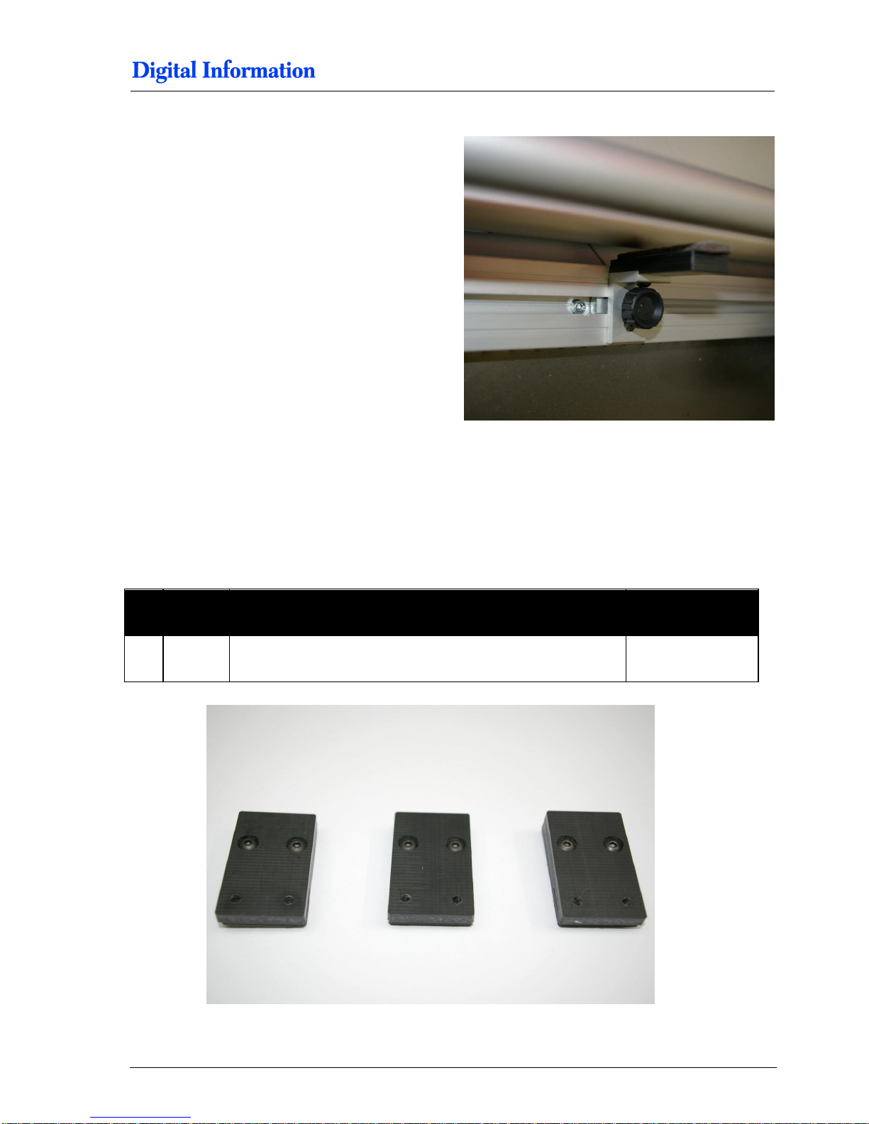
Mount the paper bracket on the right hand side, just
next the camera holder.
7.7 „Paper Jam Protector”
7.7.1 Parts
Pos Amount
Name
Dimension in mm
3 POM part
Page 52
7
Paper Entry Guide / Camera System
„Paper Jam Protector”
6-20 DJet 300-500-700 – HW Installation Manual
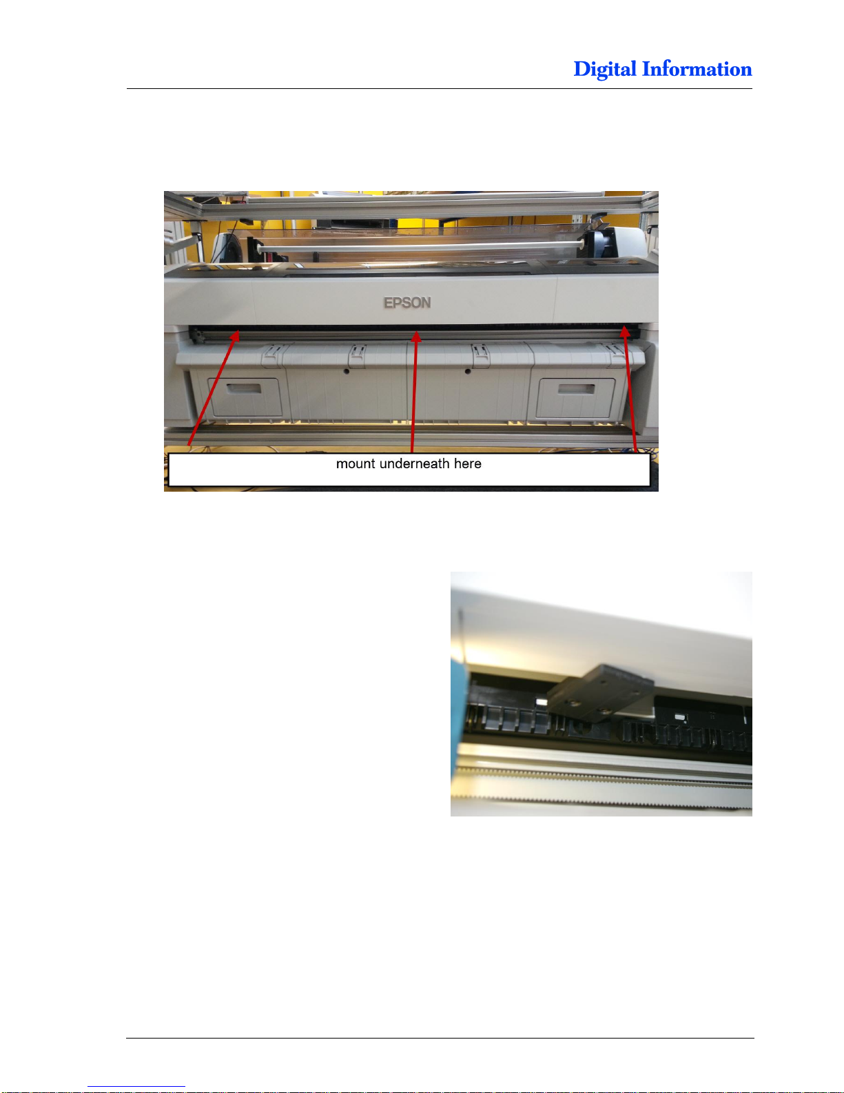
7.7.2 Positioning
7.7.3 Assembly
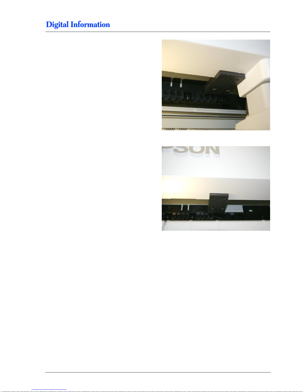
At the paper output, above the cutting system, shift
the “paper jam protector plates” sidewards into the
Epson cover.
Do this on the left side.
Page 53
Paper Entry Guide / Camera System
„Paper Jam Protector”
7
DJet 300-500-700 – HW Installation Manual 6-21
On the right side.
In the center.
Page 54
7
Paper Entry Guide / Camera System
„Paper Jam Protector”
6-22 DJet 300-500-700 – HW Installation Manual
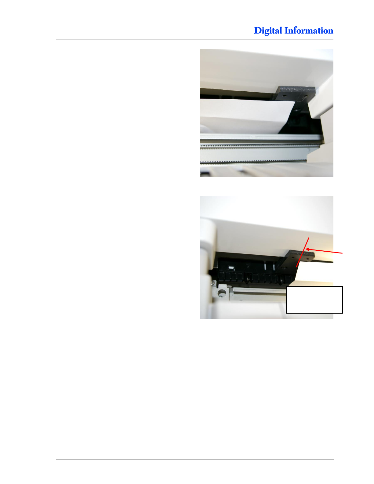
Position the plate on the right like shown.
Position the plate on the left like shown.
Place the center of the plate from the right side like:
T-7000 = 1107 mm
T-5000 = 889 mm
T-3000 = 600 mm
T-7000 = 1107 mm
T-5000 = 889 mm
T-3000 = 600 mm
Page 55
Paper Entry Guide / Camera System
„Paper Jam Protector”
7
DJet 300-500-700 – HW Installation Manual 6-23
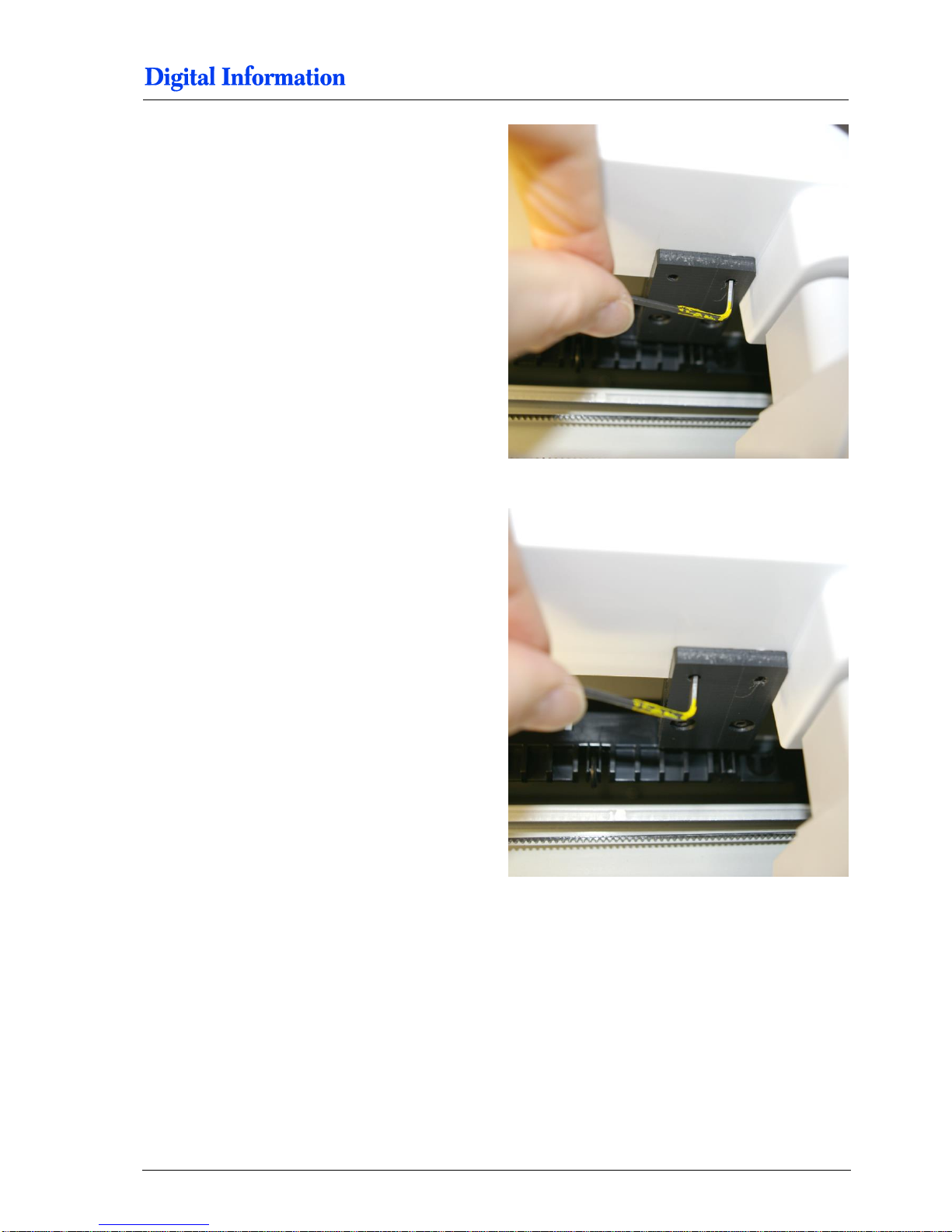
Tight both screws with a small allen range.
The plates shouldn’t move anymore.
Page 56
7
Paper Entry Guide / Camera System
Camera and LED Bar Lights for Printer Front and Back
6-24 DJet 300-500-700 – HW Installation Manual
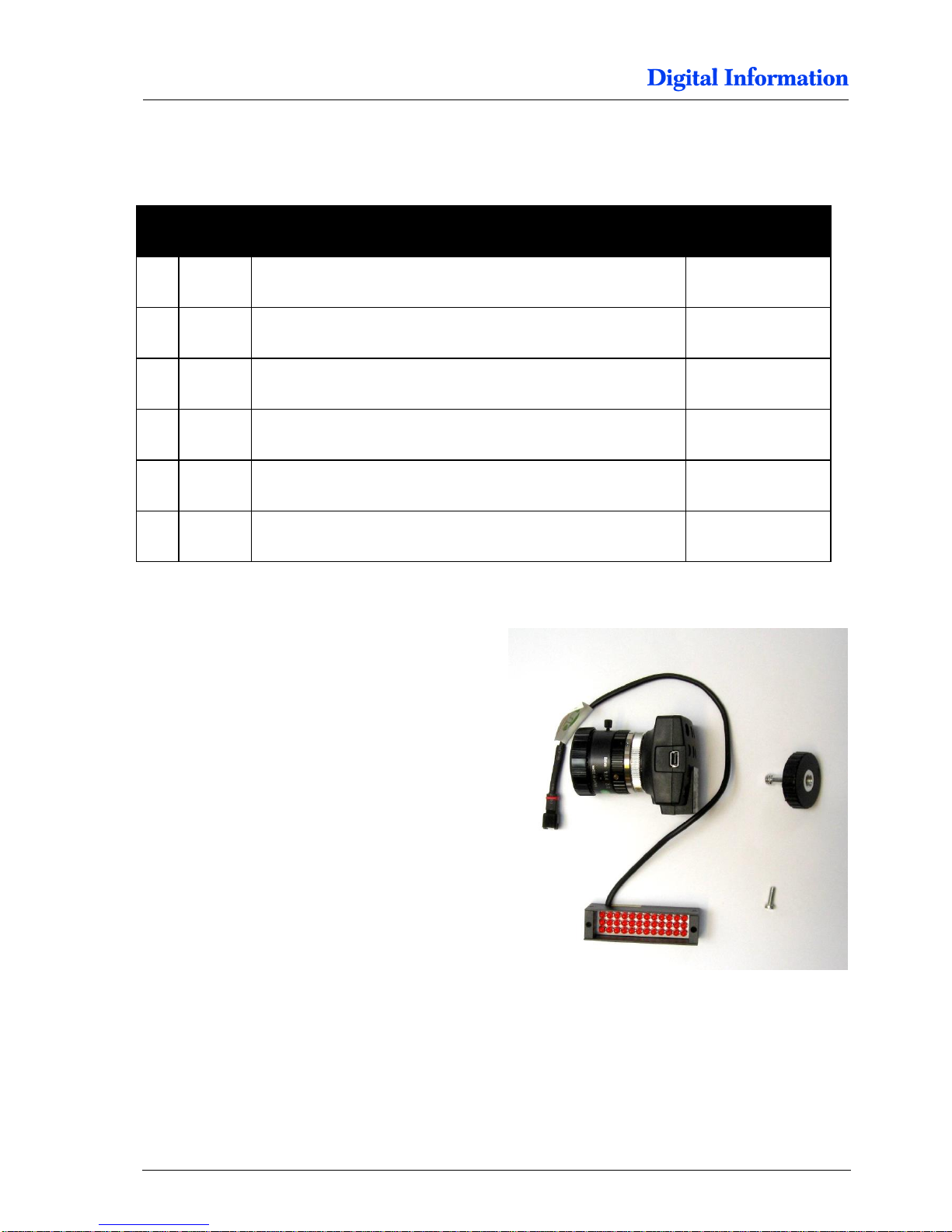
7.8 Camera and LED Bar Lights for Printer Front and Back
7.8.1 Parts for each camera system
Pos Amount
Name
Dimension in mm
71 1
Screw with M4 washer (already mounted in the LED bar light)
M3 x 10
72 1 Camera screw
73 1 Camera
74 1 Lens
75
1
Ring distance holder
76 1 LED Bar Light, red with inserted screw M3 x 10 and M4 washer
7.8.2 Assembly
Assemble the camera as shown.
Page 57
Paper Entry Guide / Camera System
Camera and LED Bar Lights for Printer Front and Back
7
DJet 300-500-700 – HW Installation Manual 6-25
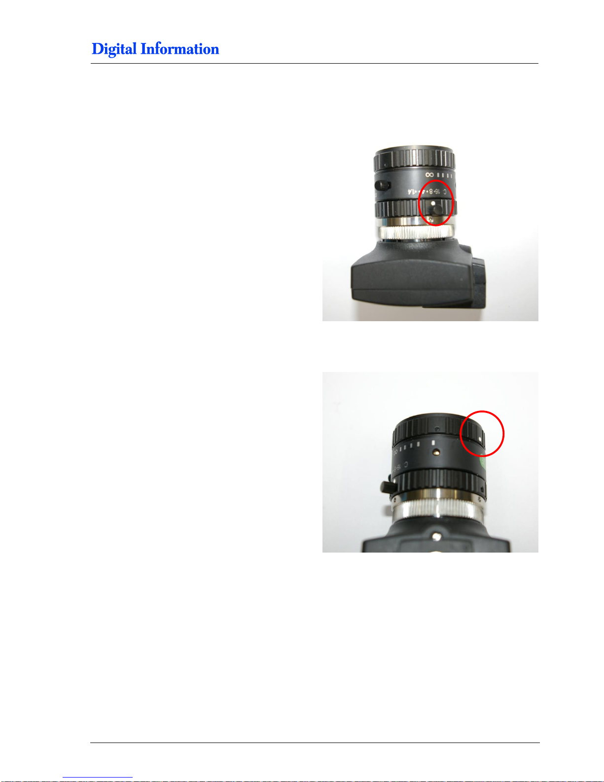
7.8.3 Camera Focus and Shutter Setup
For both cameras set the shutter between 8 and 16.
Set also the focus to close up.
Page 58

7
Paper Entry Guide / Camera System
Camera and LED Back Printer
6-26 DJet 300-500-700 – HW Installation Manual
7.9 Camera and LED Back Printer
7.9.1 LED
Use the M3 screw to bolt the LED to the camera
holder. The angle is approx. 45 degree.
Tighten it firmly.
7.9.2 Camera
Mount the camera with the camera screw.
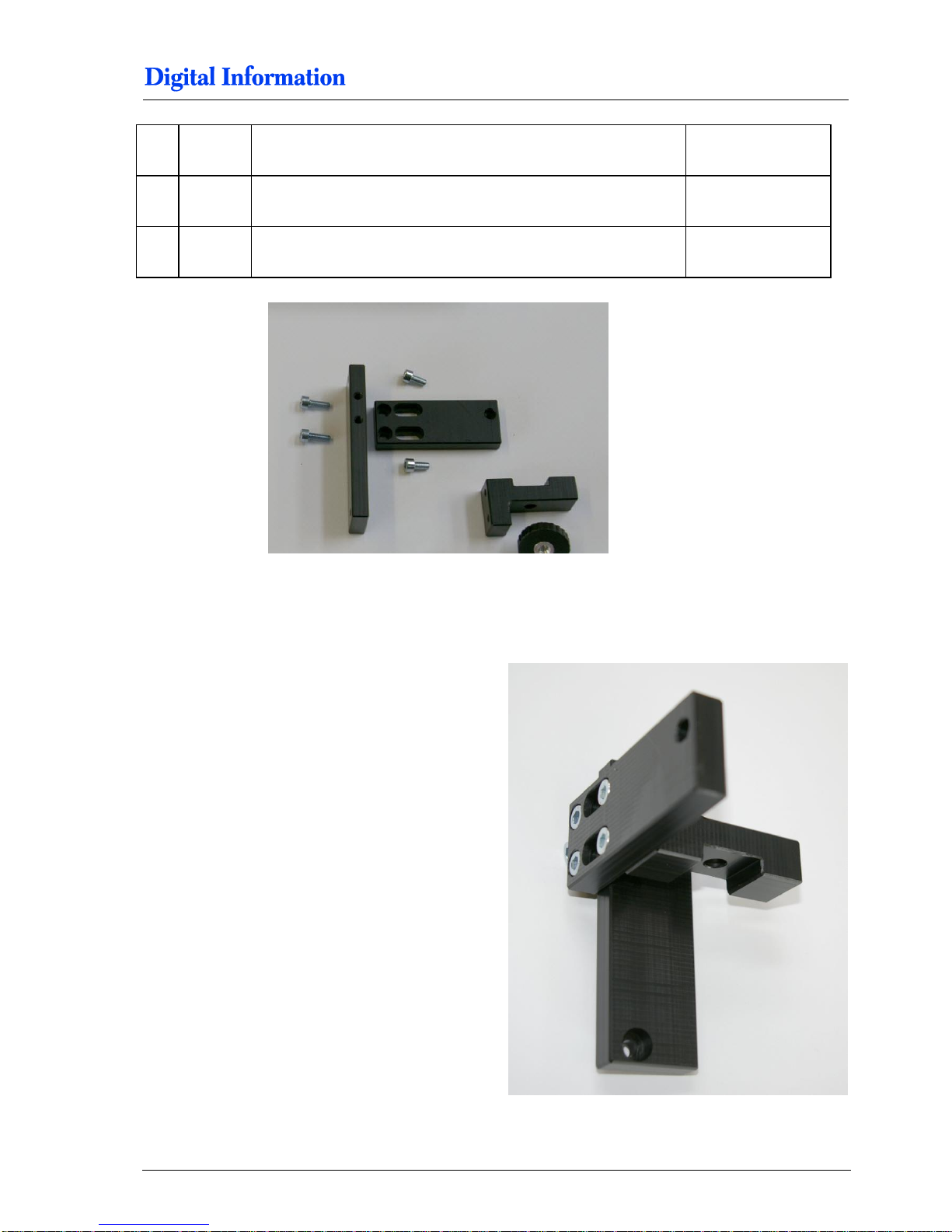
7.10 Camera Holder Front Printer
7.10.1 Parts
Pos Amount
Name
Dimension in mm
07 1 Camera holder, POM
08 1
Camera holder for Front printer , POM
Page 59
Paper Entry Guide / Camera System
Camera Holder Front Printer
7
DJet 300-500-700 – HW Installation Manual 6-27
09 1 Camera holder Front Printer, to mount to the 40x40 profile, POM
60 4
Cylinder head screw with hexagonal
M5 x 10
61 2
Cylinder head screw with hexagonal
M5 x 14
7.10.2 Assembly
Assembly now the three parts like shown.
Page 60
7
Paper Entry Guide / Camera System
Camera and LED for Front Printer
6-28 DJet 300-500-700 – HW Installation Manual
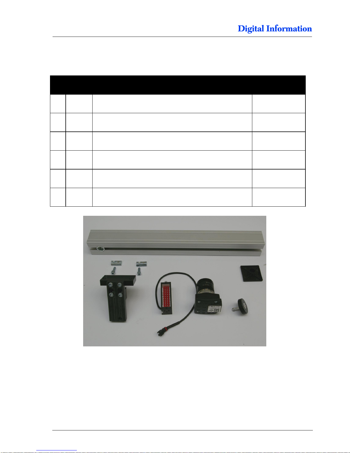
7.11 Camera and LED for Front Printer
7.11.1 Parts
Pos Amount
Name
Dimension in mm
1 Assembled Camera holder
1 Camera and LED
09 1 40x40 profile
380 mm
1 Square cover for 40x40 profile
10
2
Slot nut (half size)
M5
61 2
Cylinder head screw with hexagonal
M5 x 14
Page 61
Paper Entry Guide / Camera System
Camera and LED for Front Printer
7
DJet 300-500-700 – HW Installation Manual 6-29
7.11.2 Camera Holder
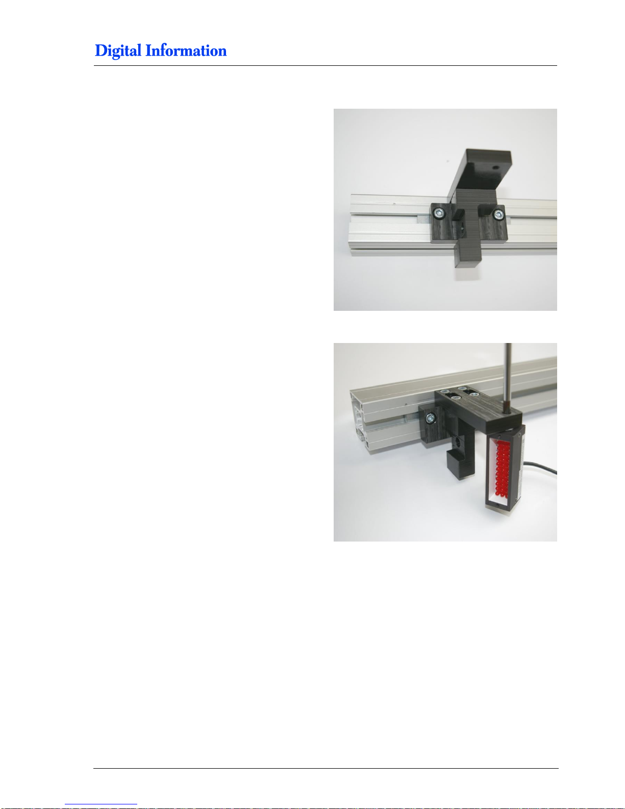
Insert two M5 slot nuts and use two M5x14 screws
to mount the camera holder.
Use the M3 screw to bolt the LED to the camera
holder. The angle is approx. 45 degree.
Tighten it firmly.
Page 62
7
Paper Entry Guide / Camera System
Camera and LED for Front Printer
6-30 DJet 300-500-700 – HW Installation Manual
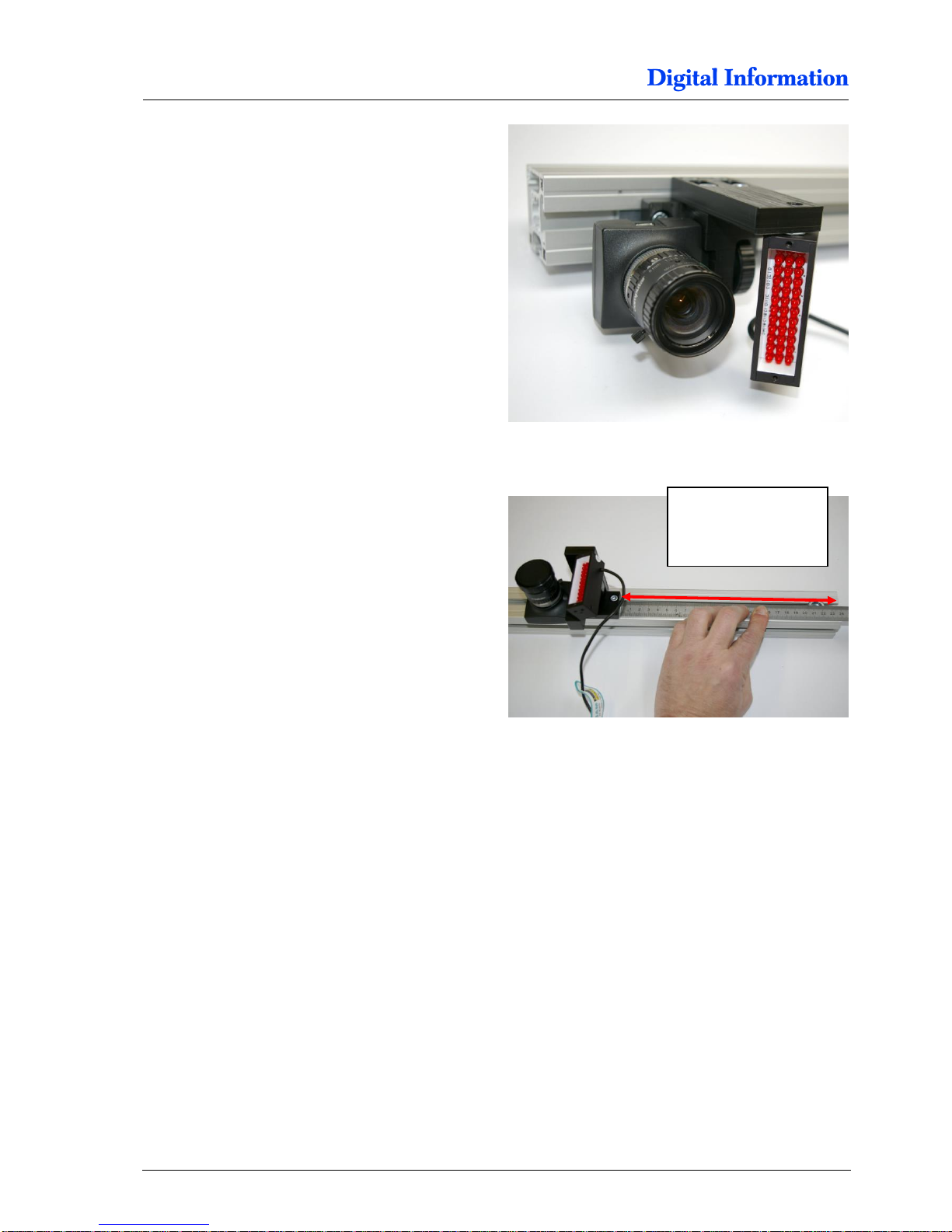
Use the camera screw to mount the camera.
Place the camera system from the profile edge as
shown in the picture.
Note
You may need to fine adjust the position of the
camera/light module sideward to get an appropriate
camera image from the code bar.
Check this when the paper is loaded and the first
“Load Job” is printed.
T7 approx. 240 mm
T5 approx. tbd mm
T3 approx. 280 mm
Page 63

Paper Entry Guide / Camera System
Camera and LED for Front Printer
7
DJet 300-500-700 – HW Installation Manual 6-31
Page 64

Page 65
Mount the Printers
Camera and LED for Front Printer
8
DJet 300-500-700 – HW Installation Manual 8-1
8 Mount the Printers
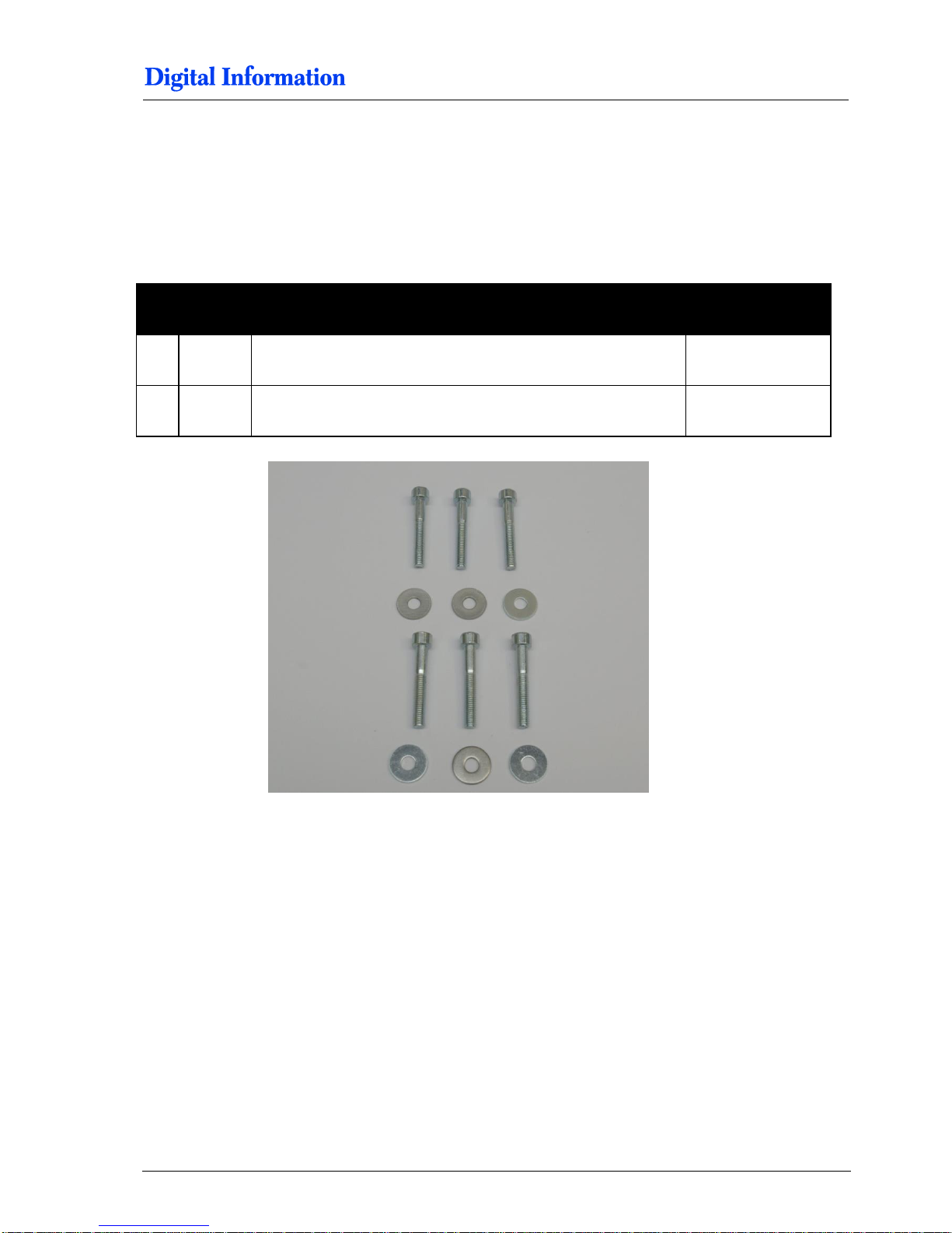
8.1.1 Parts
Pos Amount
Name
Dimension in mm
55 4 Cylinder head screw with hexagonal
M6 x 40
4 Washer
M6
Page 66
8
Mount the Printers
Camera and LED for Front Printer
8-2 DJet 300-500-700 – HW Installation Manual
8.1.2 T3000 - Rubber Foot
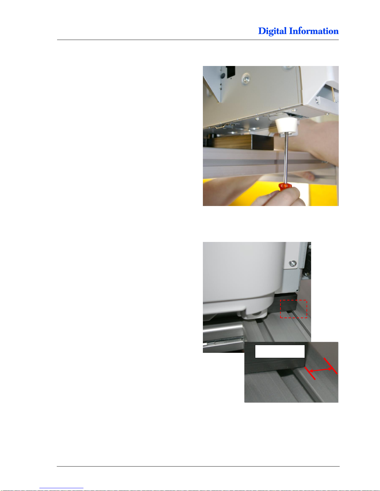
Before placing the printer to the base plate, remove
the rubber foot on both sides.
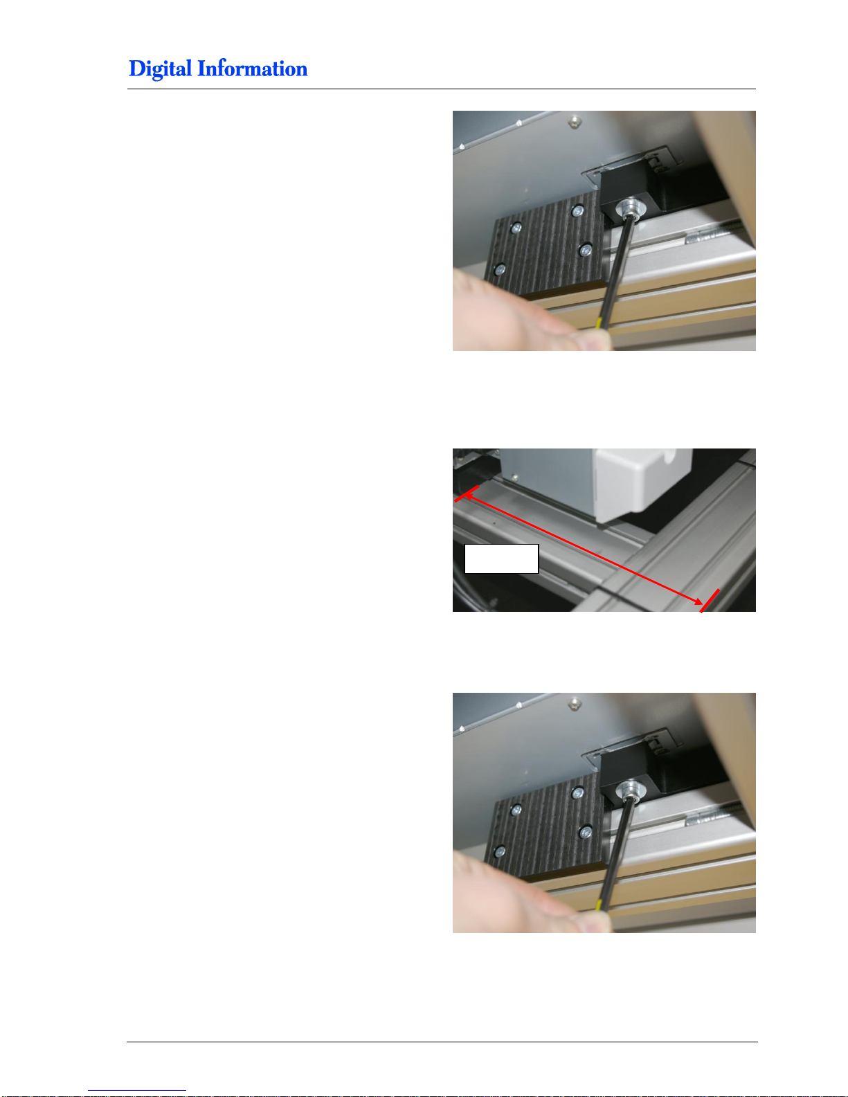
8.1.3 Mount Front Printer
The printer support plate is positioned approx. 12
mm from the profile edge.
Mount the printer and tighten all screws from the
support plate. Then tighten the screws which fix the
printer to the support plate.
approx 12 mm
Page 67
Mount the Printers
Camera and LED for Front Printer
8
DJet 300-500-700 – HW Installation Manual 8-3
Then tighten the screws which fix the printer to the
support plate.
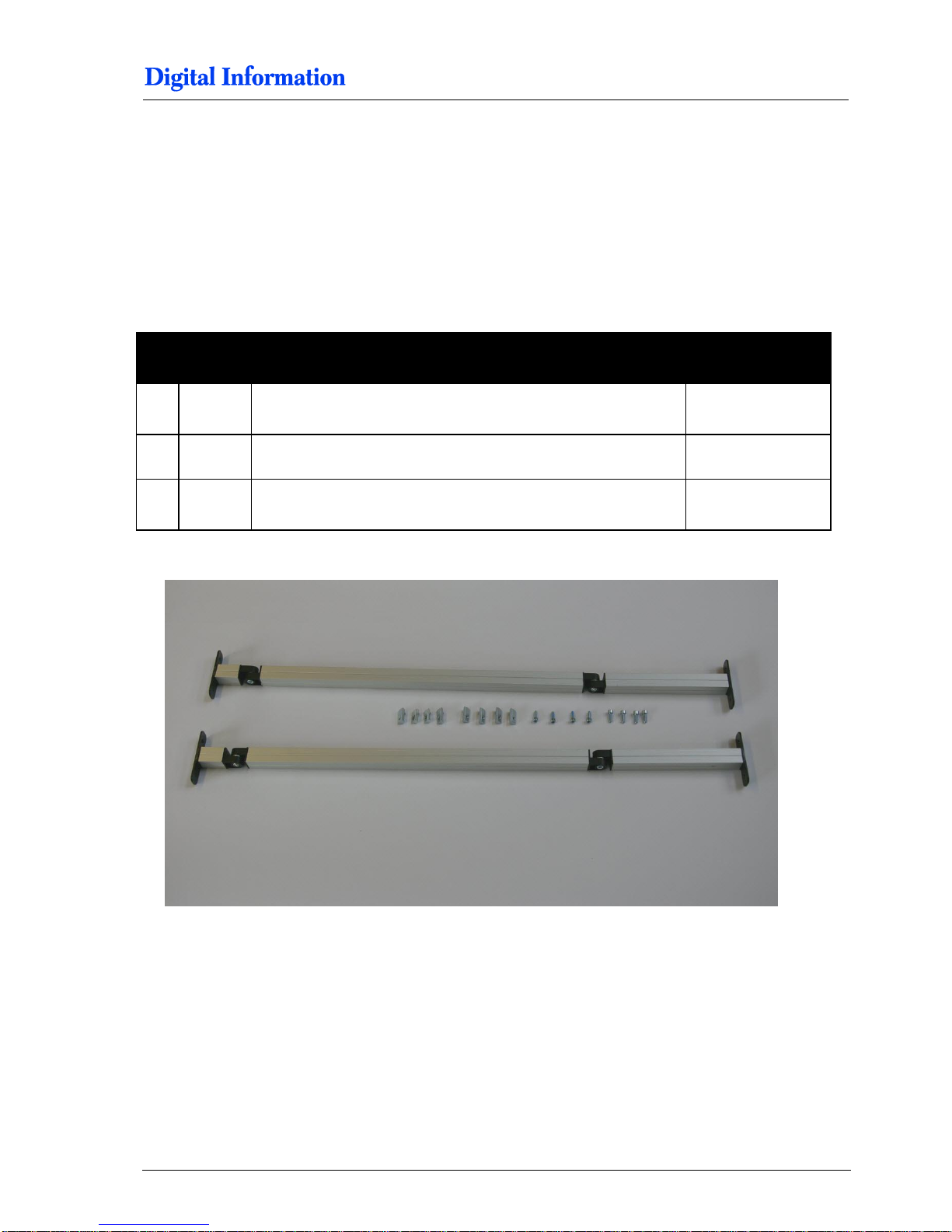
8.1.4 Mount and Position Back Printer
Position the back printer so that the distance
between the profile edge and the printer support
plate is 335 mm.
Tighten all screws from the support plate and tight
the screws from the chapter before.
8.1.5 Lock the Printer
Mount first the back printer and secure it with the
M6 screws on both sides.
Then mount the front printer and secure it.
335 mm
Page 68

8
Mount the Printers
Camera and LED for Front Printer
8-4 DJet 300-500-700 – HW Installation Manual
Page 69
Paper Tension Guide and Deflection Rollers
Paper Tension Guide
9
DJet 300-500-700 – HW Installation Manual 9-1
9 Paper Tension Guide and Deflection Rollers
9.1 Paper Tension Guide
9.1.1 Parts for Paper Tension Guide
Pos Amount
Name
Dimension in mm
66 8
Slot nut (full size)
M5
8 Cylinder head screw with hexagonal
M5 x 14
2 Paper tension guide
Page 70
9
Paper Tension Guide and Deflection Rollers
Paper Tension Guide
9-2 DJet 300-500-700 – HW Installation Manual
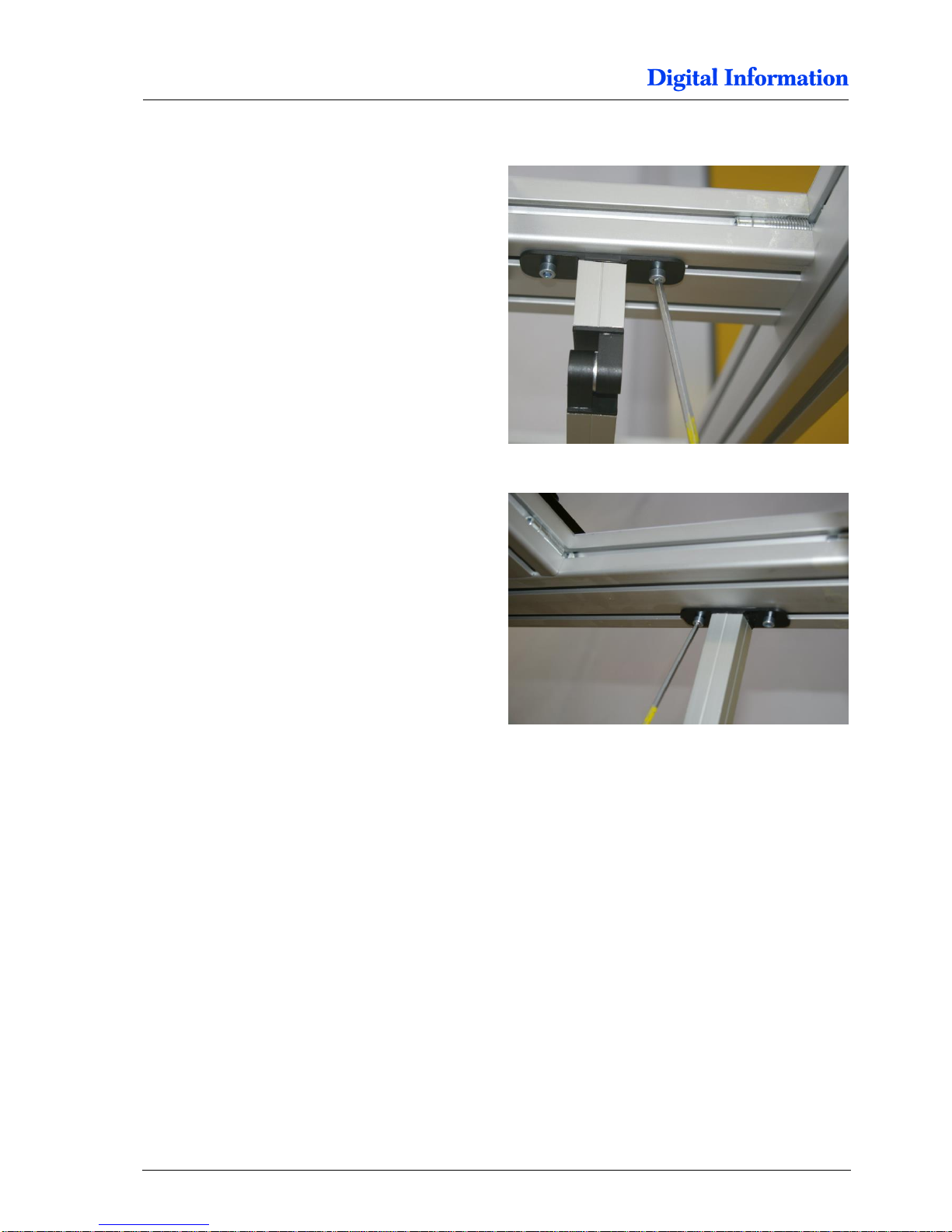
9.1.2 Tension Guide, Right Side
First, add two slot nuts M5 (full size) into the profile.
Then mount with the M5 screw the tension guide.
Note
Use only the full size M5 slot nuts.
Do the same on the other side of the frame.
Page 71
Paper Tension Guide and Deflection Rollers
Paper Tension Guide
9
DJet 300-500-700 – HW Installation Manual 9-3
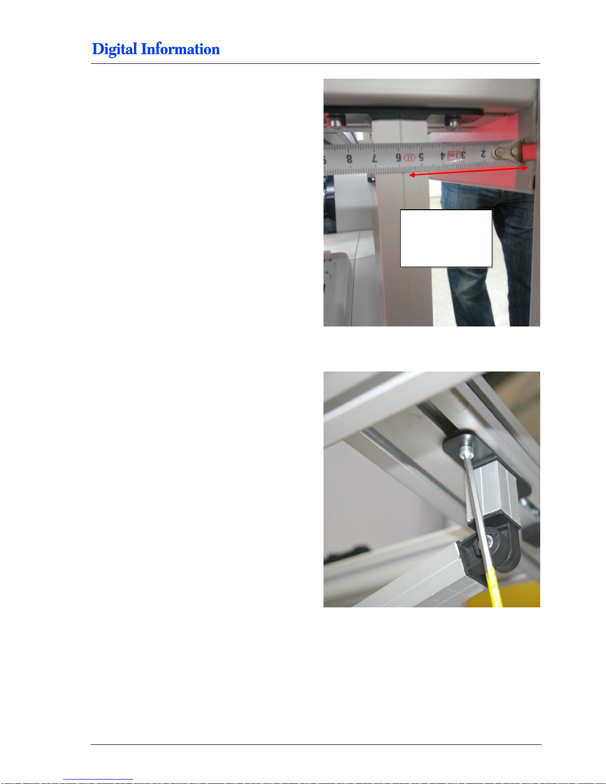
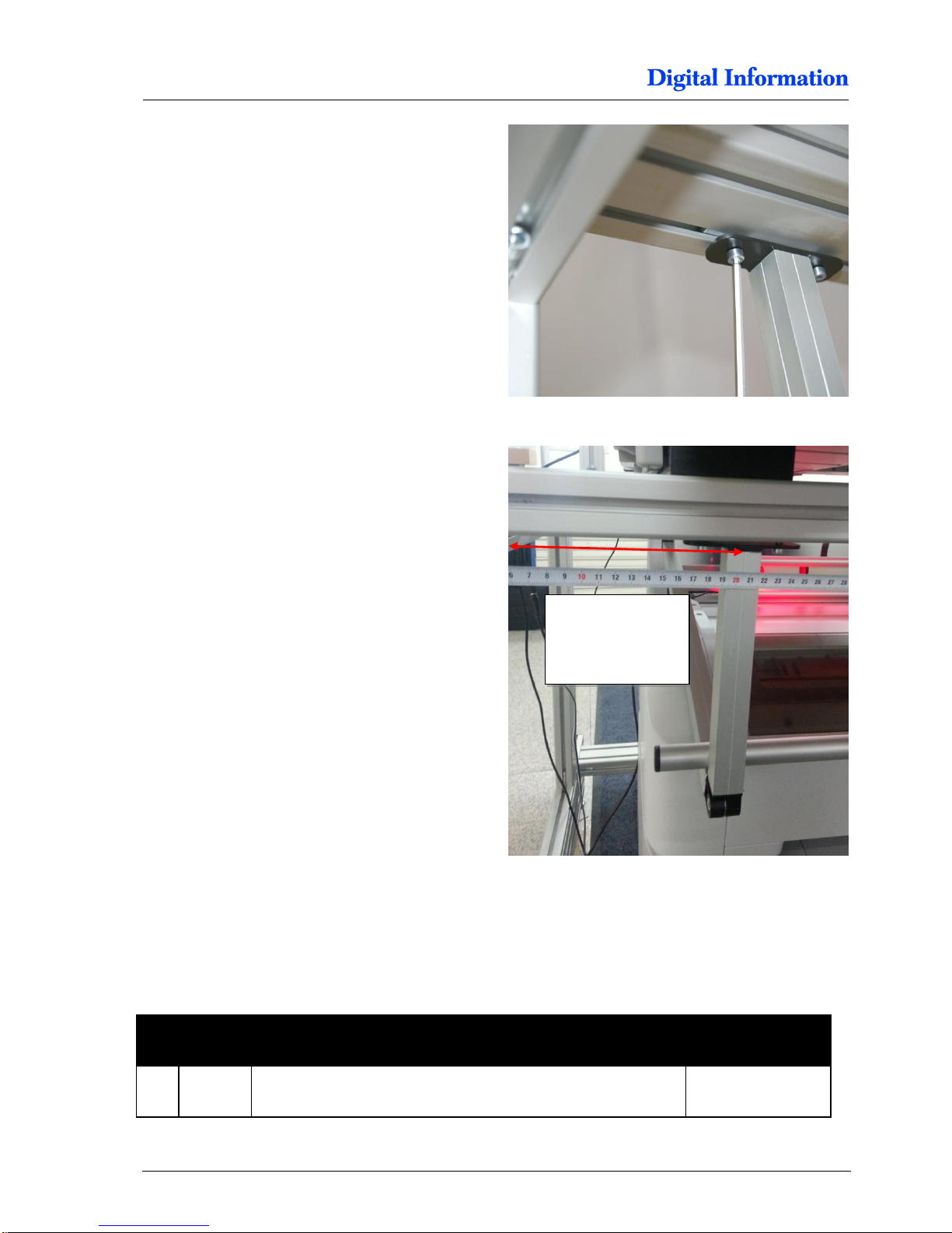
Position the center line of the 25mm profile 65 mm
from the right profile edge.
The photo is taken from the paper exit side of the
back printer.
9.1.3 Tension Guide, Left Side
First, add two slot nuts M5 (full size) to the profile.
Then mount with the M5 screw the tension guide.
T7000 65 mm
T5000 TBD
T3000 90 mm
Page 72
9
Paper Tension Guide and Deflection Rollers
Lower Deflection Roller
9-4 DJet 300-500-700 – HW Installation Manual
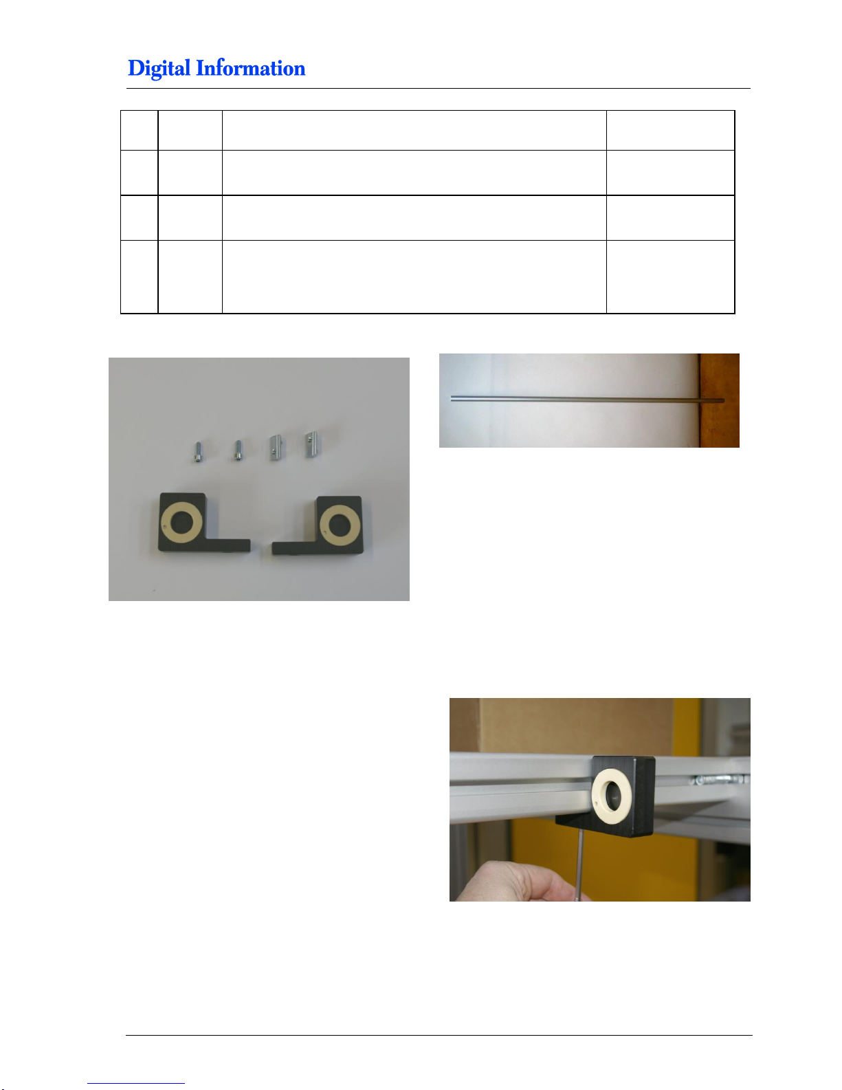
Do the same on the other side of the frame.
Position the center line of the 25mm profile, 210 mm
from the left profile edge.
9.2 Lower Deflection Roller
9.2.1 Parts
Pos Amount
Name
Dimension in mm
67 2
Slot nut (full size)
M5
T7000 210 mm
T5000 TBD
T3000 165 mm
Page 73
Paper Tension Guide and Deflection Rollers
Lower Deflection Roller
9
DJet 300-500-700 – HW Installation Manual 9-5
68 2 Cylinder head screw with hexagonal
M5 x 14
1 Deflection roller holder left
1 Deflection roller holder right
72 1 Aluminum roller 20mm
T7000: 1228 mm
T5000: TBD mm
T3000: 720 mm
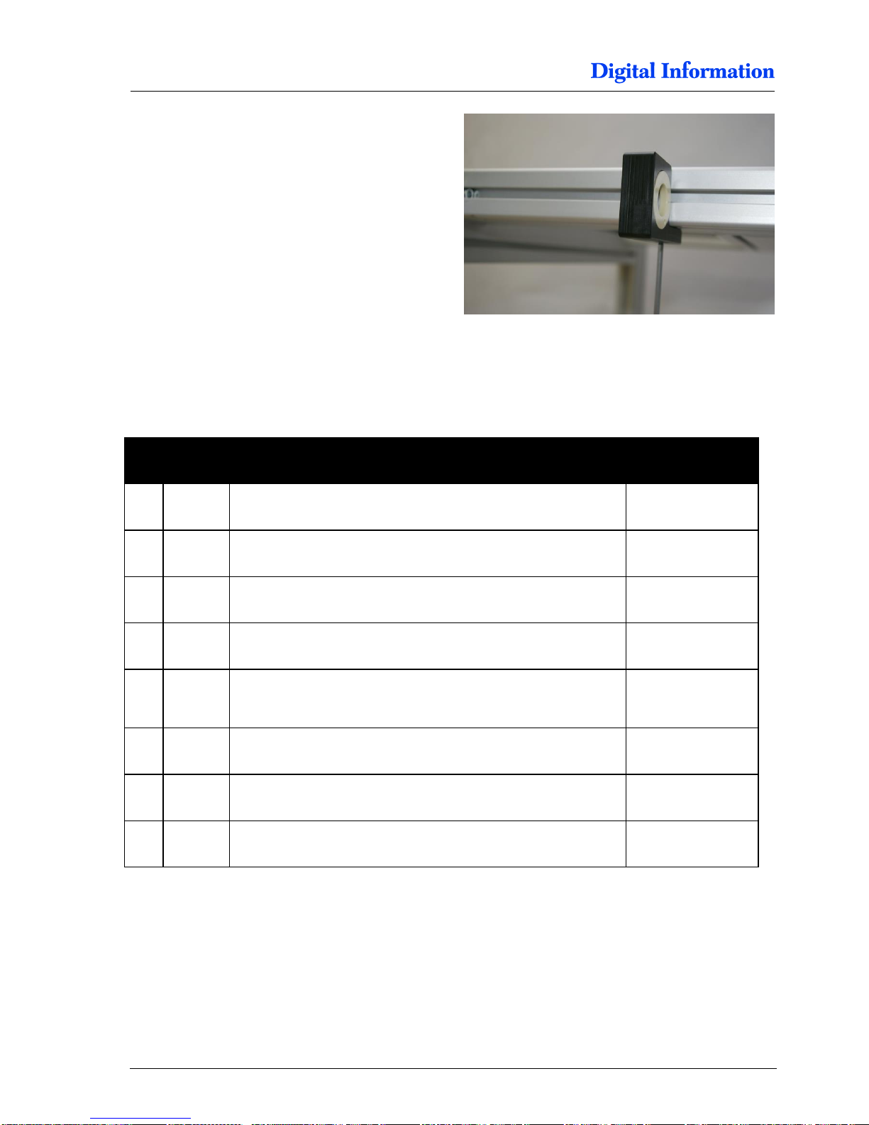
9.2.2 Deflection Roller Holder
First, add one slot nuts M5 (full size) to the profile.
Then mount with the M5 screw the holder.
Note
Use only the full size M5 slot nuts.
Page 74
9
Paper Tension Guide and Deflection Rollers
Upper Deflection Roller
9-6 DJet 300-500-700 – HW Installation Manual
Do the same on the opposite site and place the
20mm roller between the two holders.
Center it.
9.3 Upper Deflection Roller
9.3.1 Parts
Pos Amount
Name
Dimension in mm
1 40x40 profile with mounted camera system
380 mm
1 40 x 40 profile (vertical left)
310 mm
1 40 x 40 profile(vertical right)
440 mm
2 Deflection holder with bearing
72 1 Aluminum roller 20mm
T7000: 1590 mm
T5000: 1387 mm
T3000: 1140 mm
4 Slot nut (half size)
M5
4 Cylinder head screw with hexagonal
M5 x 22
2 Square cover for 40x40 profile
Page 75
Paper Tension Guide and Deflection Rollers
Upper Deflection Roller
9
DJet 300-500-700 – HW Installation Manual 9-7
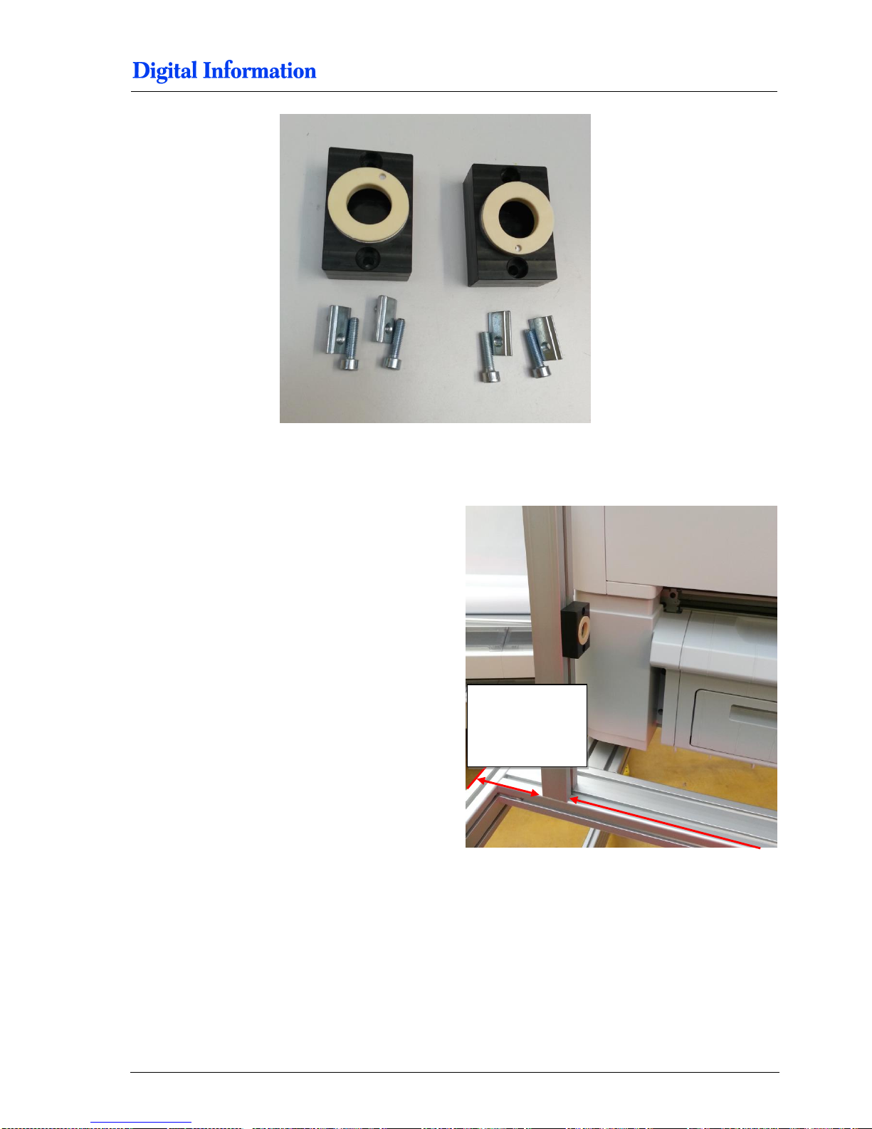
9.3.2 Assembly
First, mount the left handed profile. The distance
between the 40x40 profile and the profile edge is:
T7000 80 mm
T5000 180 mm
T3000 47 mm
Then add two M5 slot nuts into the 40x40 profile
and mount the deflection holder, 238 mm above the
cross beam.
T7000 80 mm
T5000 180 mm
T3000 47 mm
Page 76
9
Paper Tension Guide and Deflection Rollers
Upper Deflection Roller
9-8 DJet 300-500-700 – HW Installation Manual
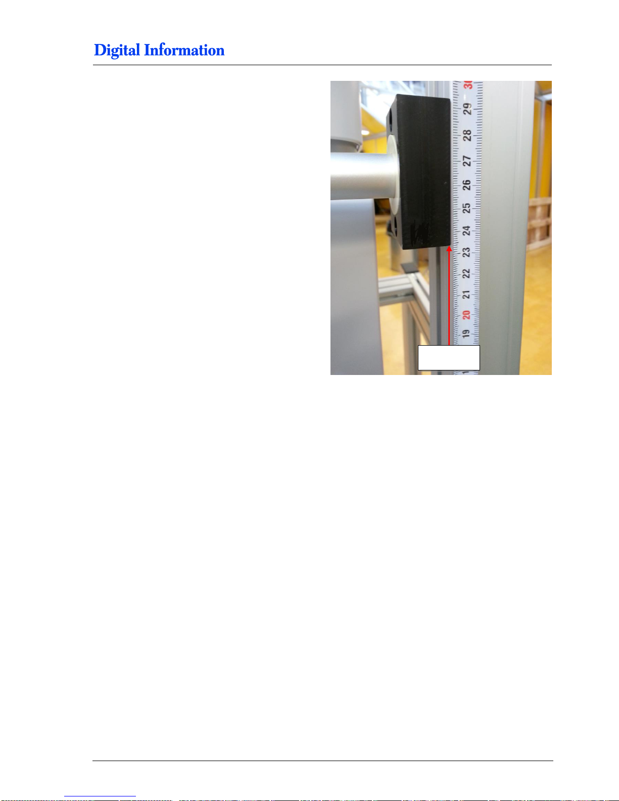
Add two M5 slot nuts into the 40x40 profile and
mount the deflection holder 238 mm above the
cross beam profile.
Mount the 40x 40 profile and add the deflection
roller between the two 40x40 profiles.
Set the distance (inner side to inner side):
T7000 1631 mm
T5000 1428 mm
T3000 1156 mm
Overview.
T7000 1631 mm
T5000 1428 mm
T3000 1156 mm
Page 77
Paper Tension Guide and Deflection Rollers
Upper Deflection Roller
9
DJet 300-500-700 – HW Installation Manual 9-9
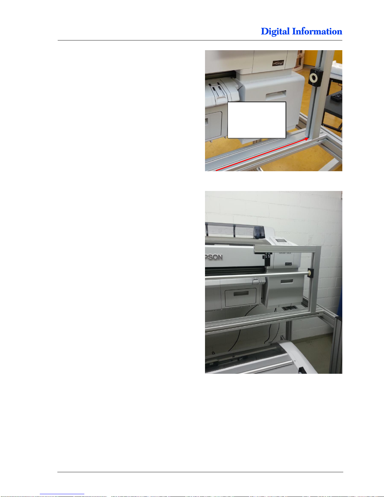
The distance between the deflection roller holder
and the cross beam profile is precisely 238 mm.
Mount the 40x40x380mm profile where in chapter 7
the cameras has been mounted to on the top right
side of the 40x40 profile.
Use the black caps to cover the end of the 40x40
profile.
238 mm
Page 78

9
Paper Tension Guide and Deflection Rollers
Upper Deflection Roller
9-10 DJet 300-500-700 – HW Installation Manual
Page 79
Line up the Printers
Paper Entry Back Printer
10
DJet 300-500-700 – HW Installation Manual 10-1
10 Line up the Printers
10.1 Paper Entry Back Printer
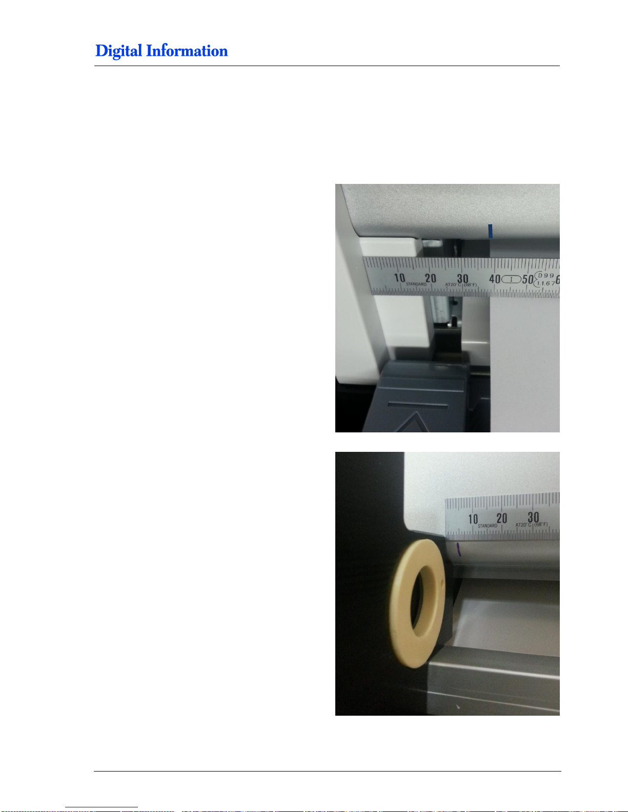
The left paper edge goes into the back printer 39
mm from the shown position. As a positioning help,
draw a mark on the printer case.
The distance between the roll holder and the mark
(paper entry) should be approx. 4 mm.
Page 80

10
Line up the Printers
Paper Entry Back Printer
10-2 DJet 300-500-700 – HW Installation Manual
Page 81
11
Printer Panel Configuration
Parameter Setup for FRONT and BACK Printer
10-2 DJet 300-500-700 – HW Installation Manual
11 Printer Panel Configuration
11.1 Parameter Setup for FRONT and BACK Printer
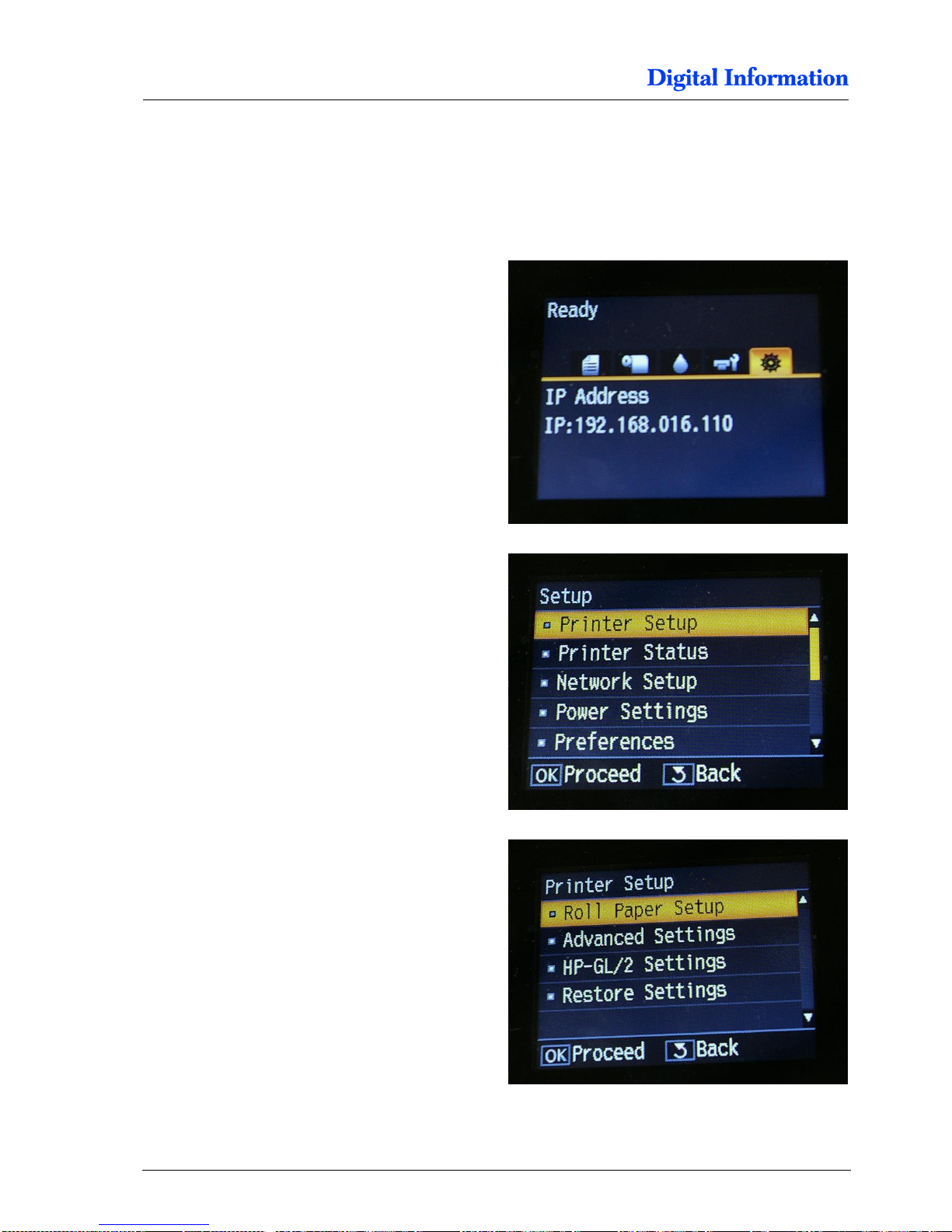
At the printer change to the menu “setup”
Select “Printer Setup”.
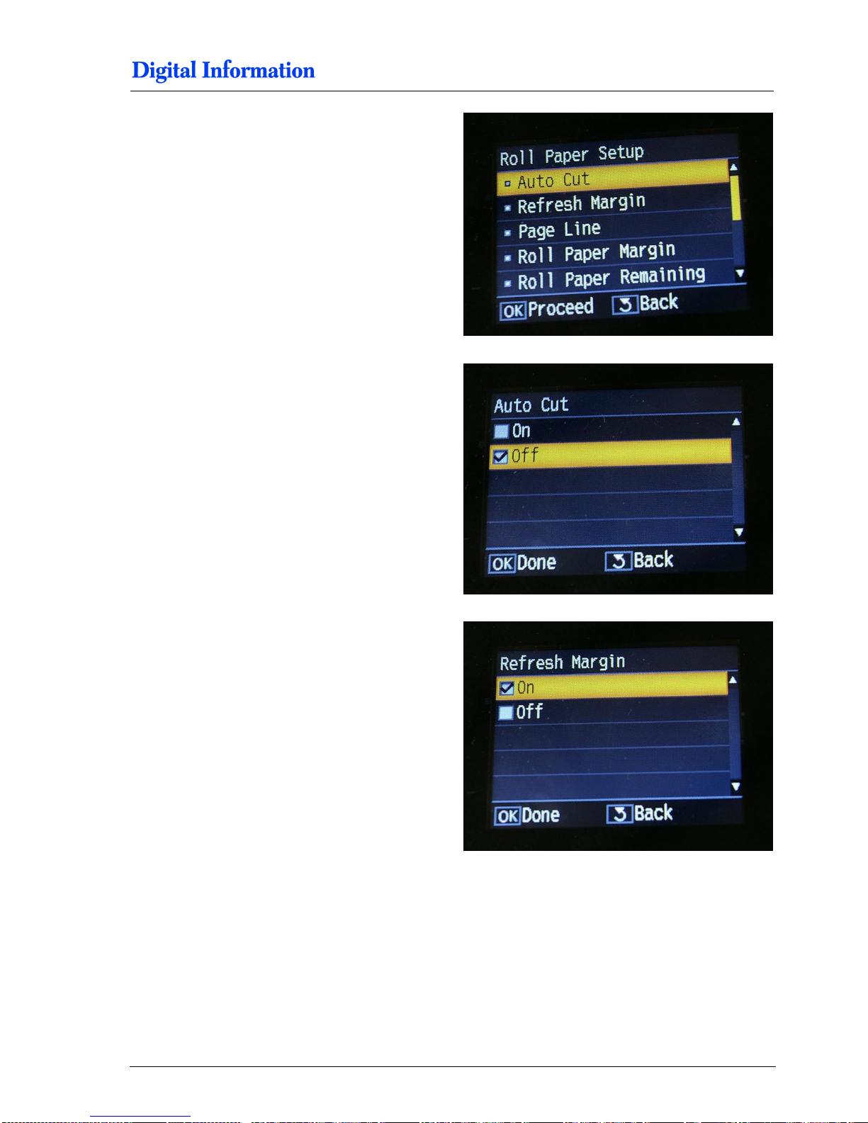
Select “Roll Paper Setup”.
Page 82
Printer Panel Configuration
Parameter Setup for FRONT and BACK Printer
11
DJet 300-500-700 – HW Installation Manual 10-3
In the menu “Roll Paper Setup”, set the values as
followed:
Set “Auto Cut” = OFF
Set “Refresh Margin” = ON
Page 83
11
Printer Panel Configuration
Parameter Setup for FRONT and BACK Printer
10-4 DJet 300-500-700 – HW Installation Manual
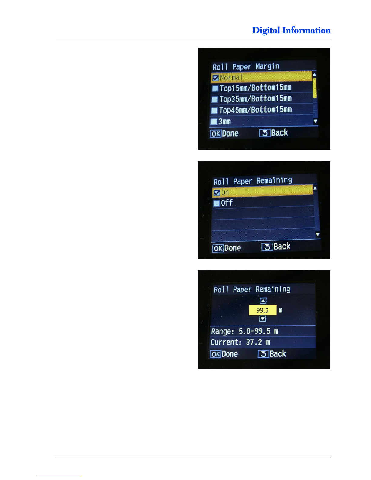
Set “Roll Paper Margin” = Normal
For the front printer only:
Set “Roll Paper Remaining” = ON
For the front printer only:
Set “Roll Paper Remaining” to 99,5 m (roll length).
For the DJet300 use 75m.
Page 84
Printer Panel Configuration
Parameter Setup for FRONT and BACK Printer
11
DJet 300-500-700 – HW Installation Manual 10-5
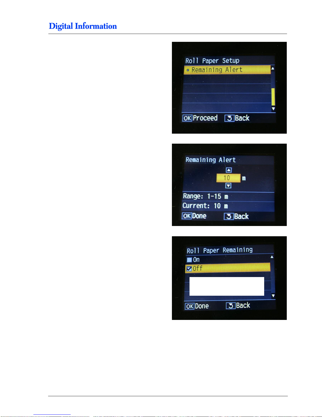
For the front printer only:
Select “Remaining Alert”.
For the front printer only:
Set the “Remaining Alert” = 10 m
For the back printer only:
Set “Roll Paper Remaining” = OFF
BACK PRINTER ONLY
Page 85
11
Printer Panel Configuration
Parameter Setup for FRONT and BACK Printer
10-6 DJet 300-500-700 – HW Installation Manual
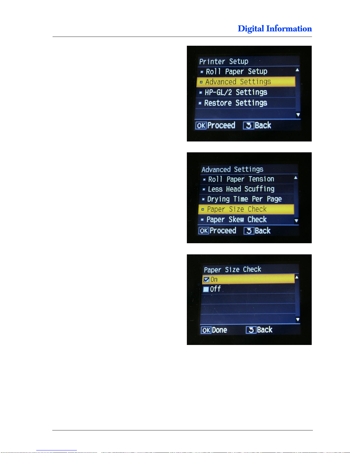
Select “Advanced Settings”.
In the menu “Advanced Settings”, set the values as
followed:
Set “Paper Size Check” = ON
Page 86
Printer Panel Configuration
Parameter Setup for FRONT and BACK Printer
11
DJet 300-500-700 – HW Installation Manual 10-7
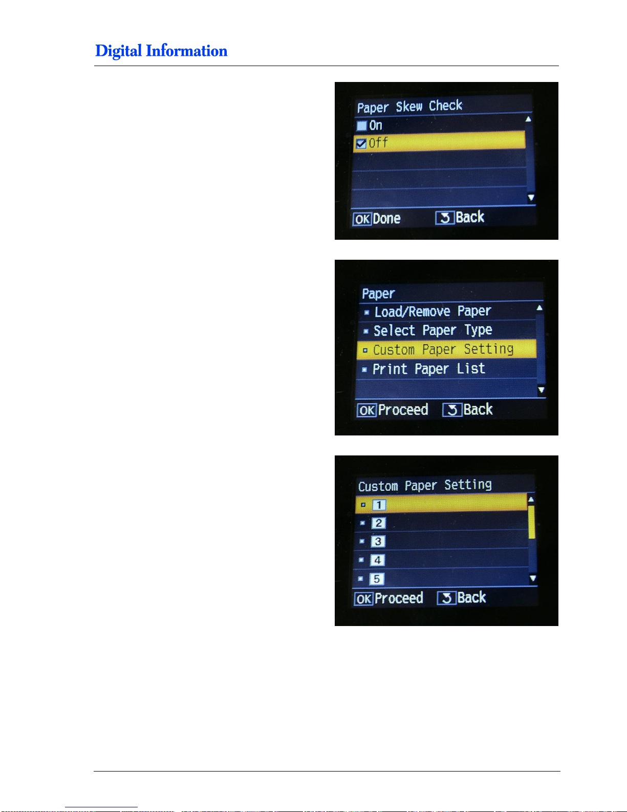
Set “Paper Skew Check” = OFF
In the menu “Paper”, change to the submenu
“Custom Paper Setting”.
Set the DJet paper settings as following:
Select in the menu “Custom Paper Setting” the
paper Nr 1.
Page 87
11
Printer Panel Configuration
Parameter Setup for FRONT and BACK Printer
10-8 DJet 300-500-700 – HW Installation Manual
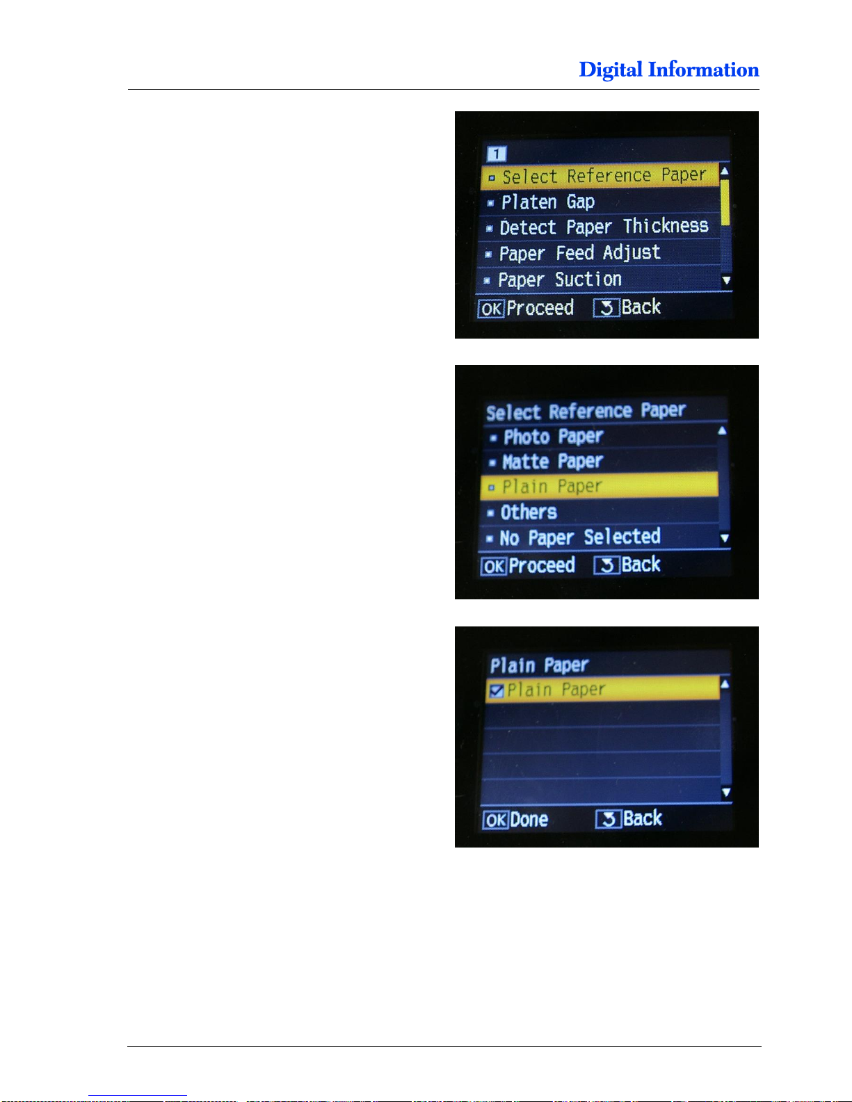
Select the menu “Select Reference Paper”.
Select the menu “Plain Paper”.
Select here “Plain Paper”.
Page 88
Printer Panel Configuration
Parameter Setup for FRONT and BACK Printer
11
DJet 300-500-700 – HW Installation Manual 10-9
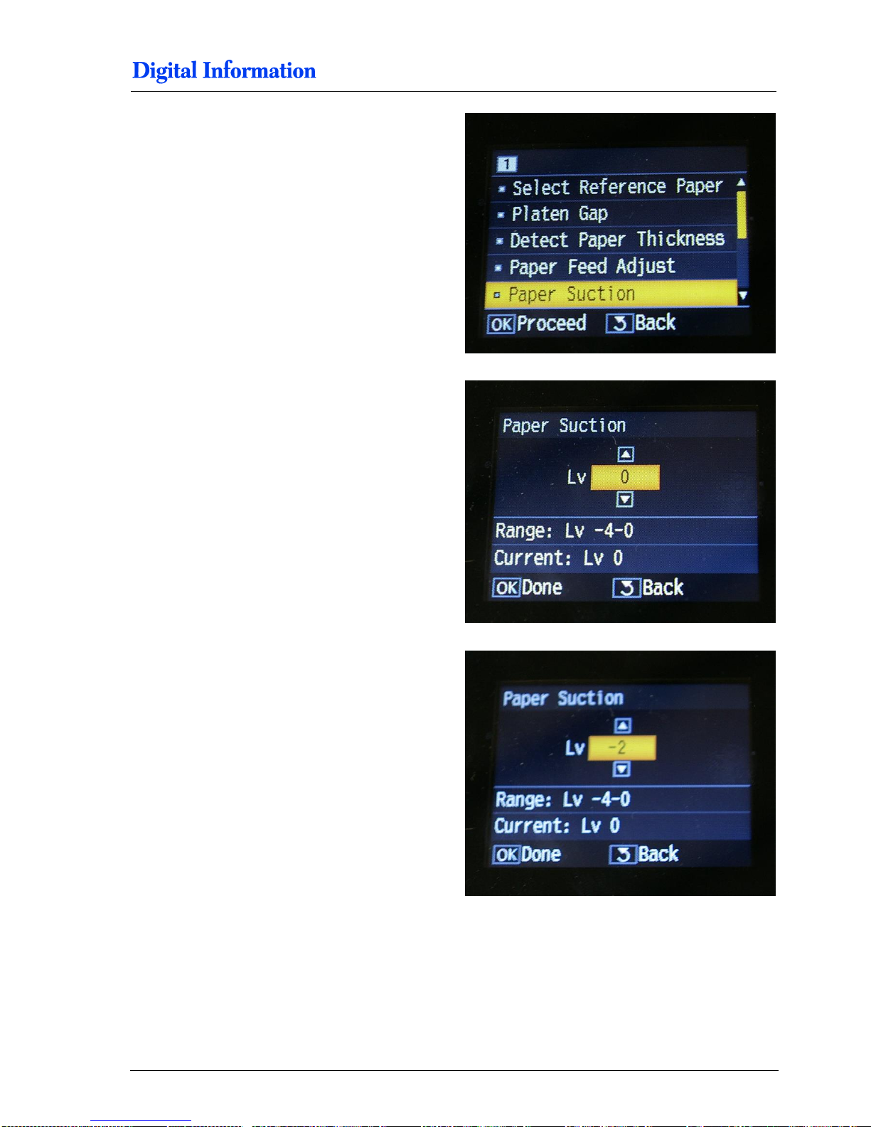
Select the menu “Paper Suction”.
For the front printer only:
Set “Paper Suction Lv” = 0
For the back printer only:
Set “Paper Suction Lv” = -2
Page 89
11
Printer Panel Configuration
Parameter Setup for FRONT and BACK Printer
10-10 DJet 300-500-700 – HW Installation Manual
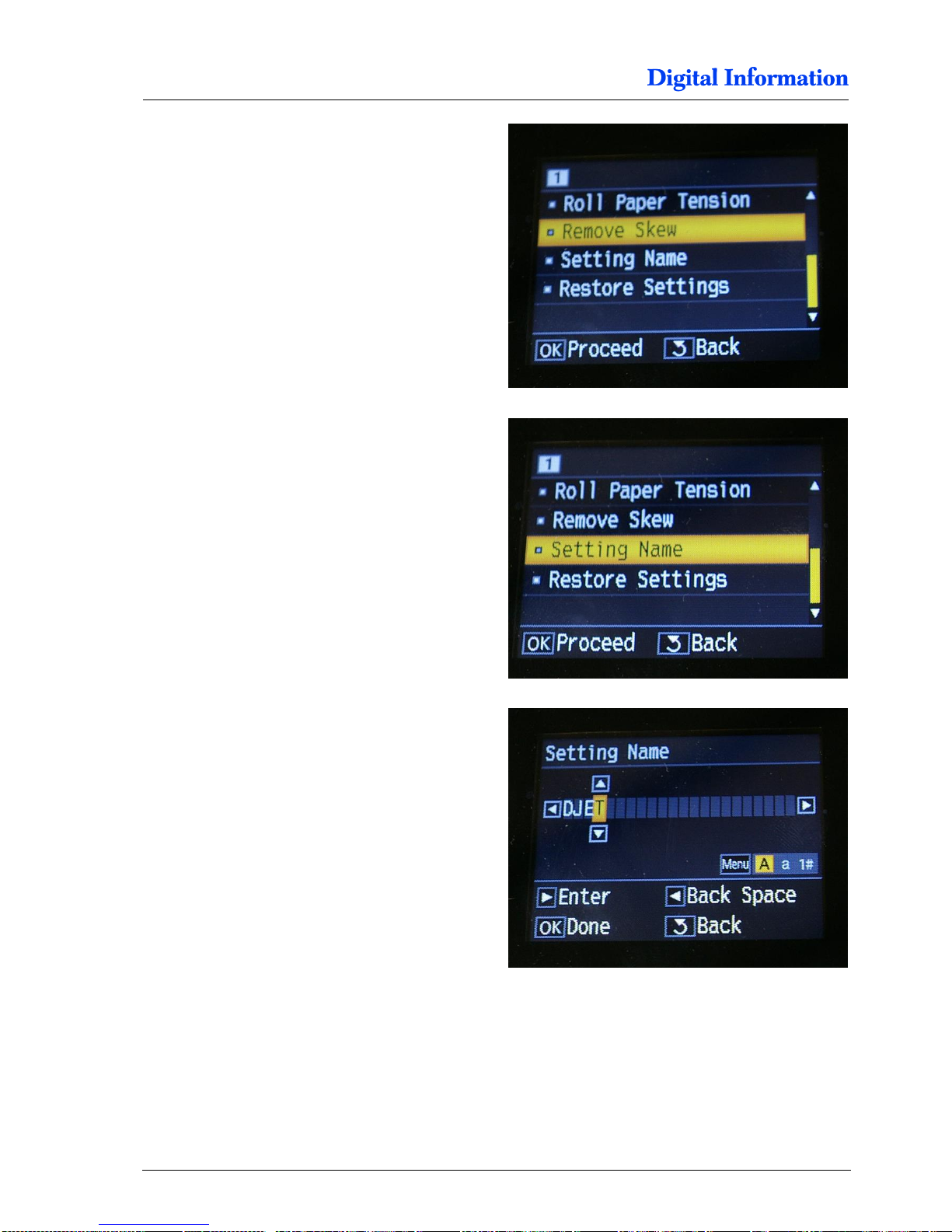
Select the menu “Remove Skew” and select OFF.
Select the menu “Setting Name”.
Enter as the setting name “DJET”
Page 90
Printer Panel Configuration
Parameter Setup for FRONT and BACK Printer
11
DJet 300-500-700 – HW Installation Manual 10-11
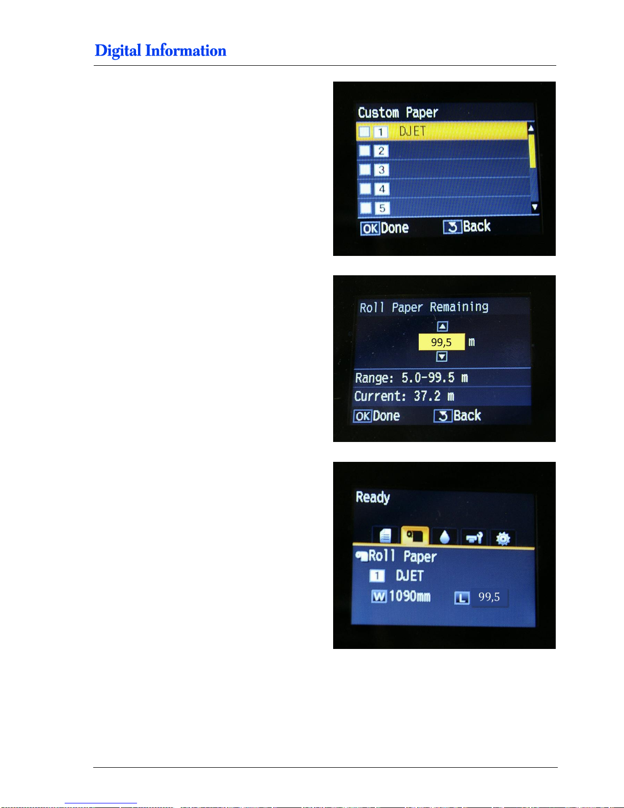
The paper “DJet” appears as custom paper nr 1.
Select the DJet Paper and set “Roll Paper
Remaining” to 99,5 m.
For the DJet300 use 75m.
When paper is loaded, the display indicates the
paper type and the paper width.
Additionally, the front printer shows the remaining
paper roll length.
Page 91
11
Printer Panel Configuration
Enable DJet Mode
10-12 DJet 300-500-700 – HW Installation Manual
11.2 Enable DJet Mode
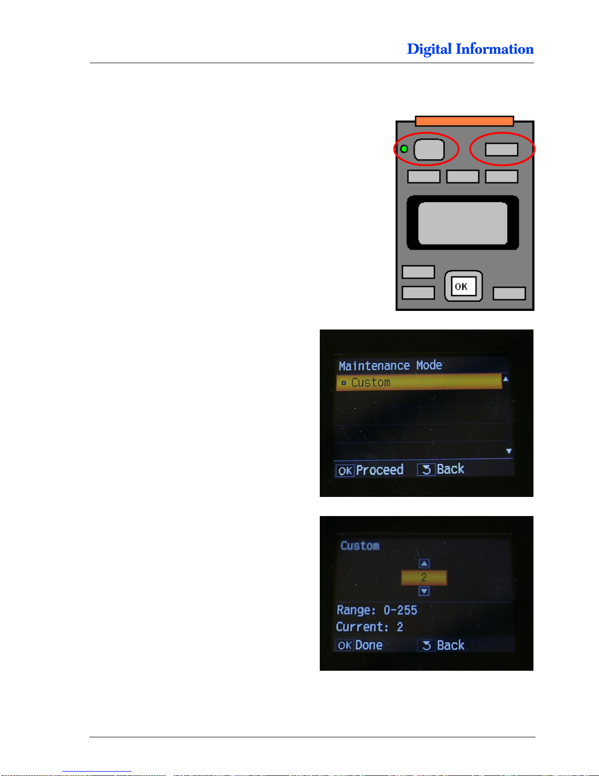
Press the Pause button and turn on the printer.
The printer starts in “Maintenance Mode”.
Set “Custom mode” = 2
Page 92

Page 93
LED Bar Light
Power Supply Setup for LED Bar Light
12
DJet 300-500-700 – HW Installation Manual 12-1
12 LED Bar Light
12.1 Power Supply Setup for LED Bar Light
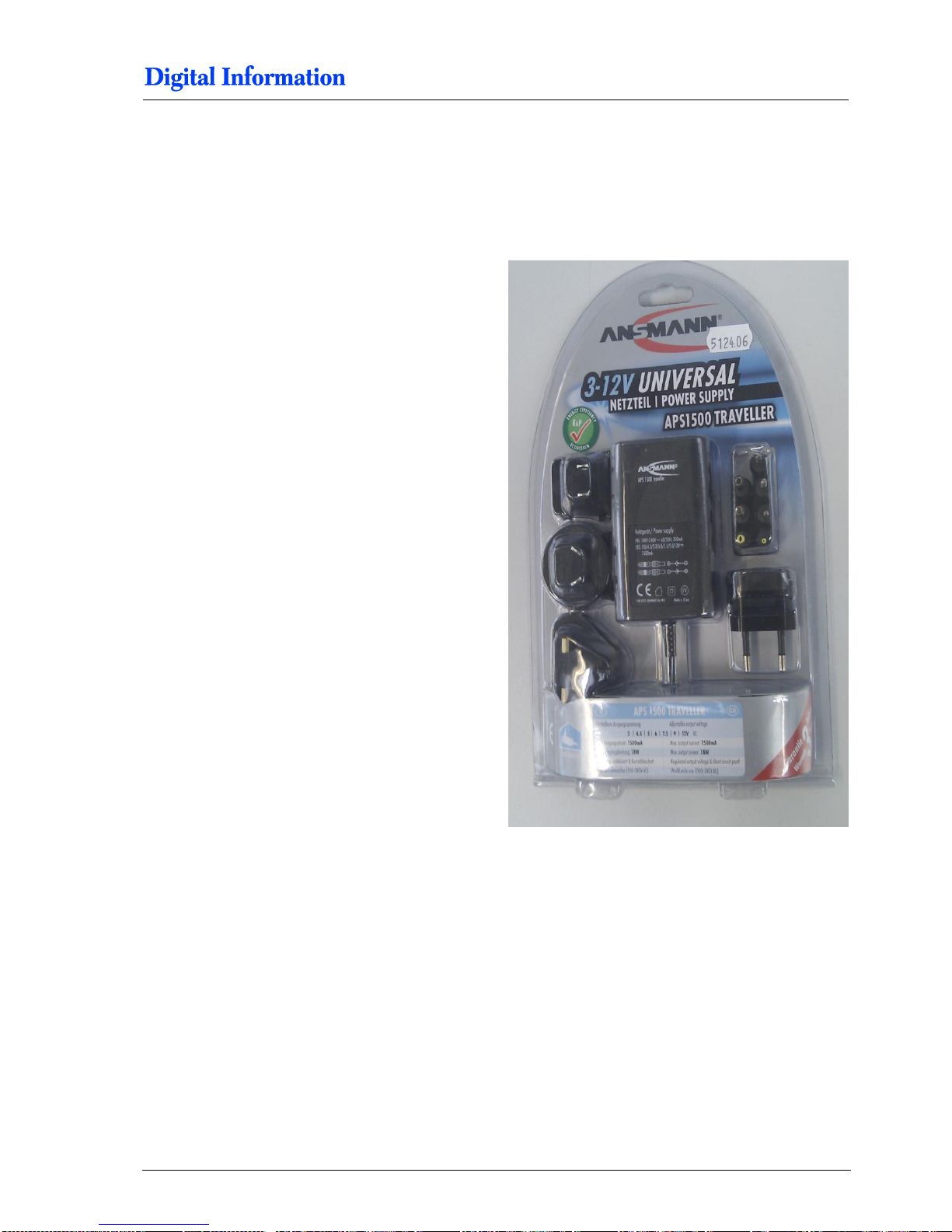
Setup the power supply for the LED bar light:
Voltage 12V
Page 94
12
LED Bar Light
Power Supply Setup for LED Bar Light
12-2 DJet 300-500-700 – HW Installation Manual
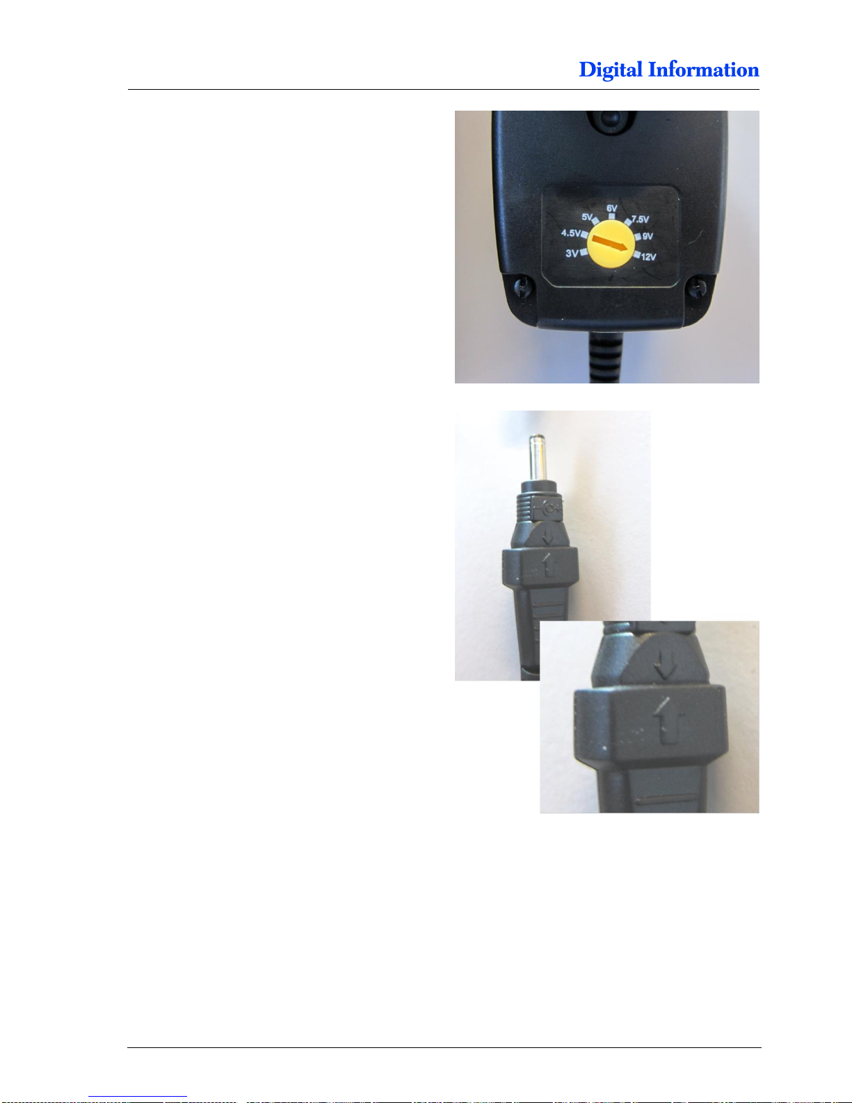
Set the output voltage to 12 V.
Select the correct tip and apply it like shown.
Page 95
LED Bar Light
Power Supply Setup for LED Bar Light
12
DJet 300-500-700 – HW Installation Manual 12-3
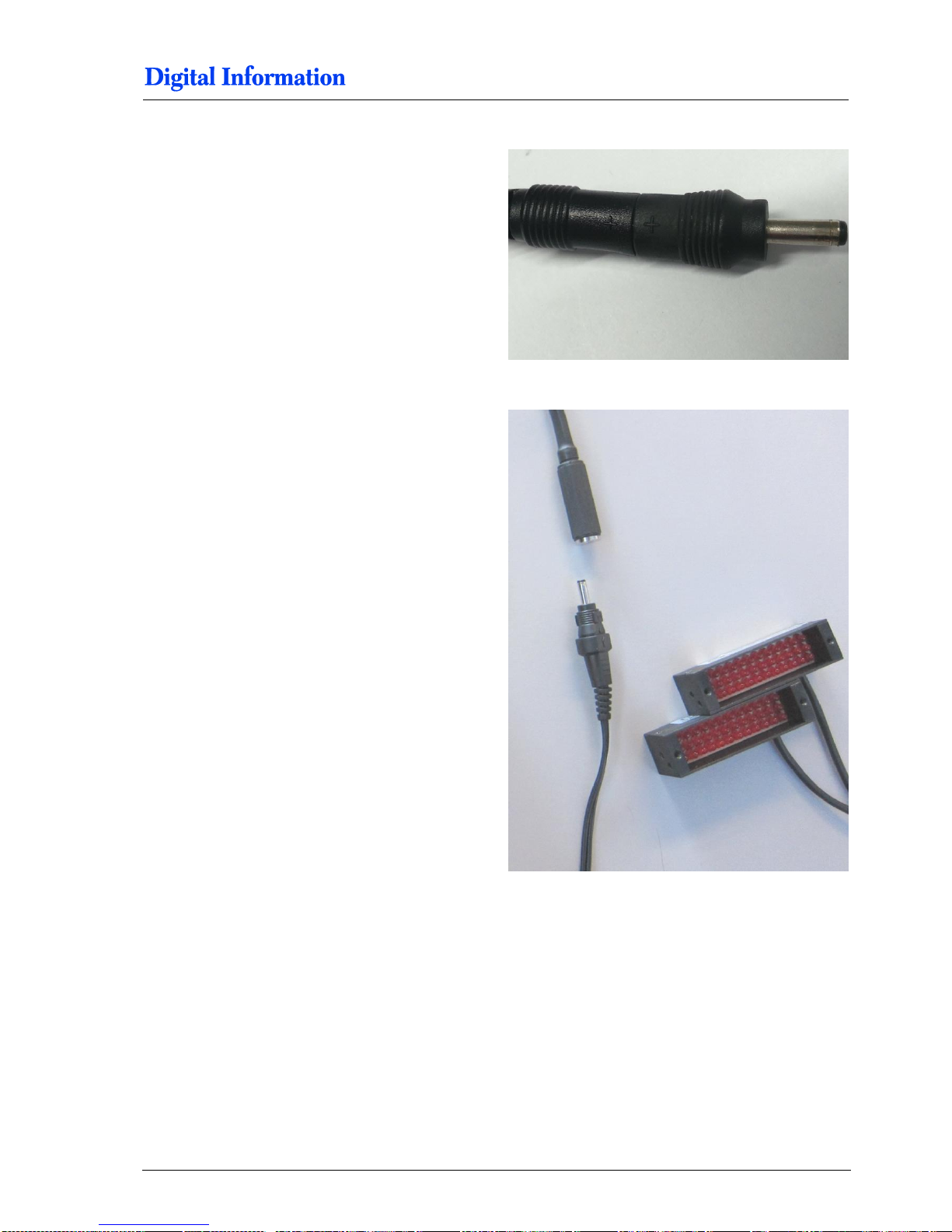
Select the correct tip and apply it like shown.
Check the cable with the LEDs.
 Loading...