

Page 1
External I/O
Technical Reference Guide
Series Series
Overview
External I/O Specification
Commands
Printer Statuses and Signals
Timing
Settings on the Printer
Appendix
M00123700
Rev.A
Page 2

Cautions
• No part of this document may be reproduced, stored in a retrieval system, or transmitted in any form or by
any means, electronic, mechanical, photocopying, recording, or otherwise, without the prior written permission of Seiko Epson Corporation.
• The contents of this document are subject to change without notice. Please contact us for the latest information.
• While every precaution has been taken in the preparation of this document, Seiko Epson Corporation
assumes no responsibility for errors or omissions.
• Neither is any liability assumed for damages resulting from the use of the information contained herein.
• Neither Seiko Epson Corporation nor its affiliates shall be liable to the purchaser of this product or third par-
ties for damages, losses, costs, or expenses incurred by the purchaser or third parties as a result of: accident,
misuse, or abuse of this product or unauthorized modifications, repairs, or alterations to this product, or
(excluding the U.S.) failure to strictly comply with Seiko Epson Corporation’s operating and maintenance
instructions.
• Seiko Epson Corporation shall not be liable against any damages or problems arising from the use of any
options or any consumable products other than those designated as Original EPSON Products or EPSON
Approved Products by Seiko Epson Corporation.
Trademarks
EPSON is a registered trademark of Seiko Epson Corporation.
Exceed Your Vision is registered trademarks or trademarks of Seiko Epson Corporation.
All other trademarks are the property of their respective owners and used for identification purpose only.
©Seiko Epson Corporation 2019-2020. All rights reserved.
2
Page 3

Restriction of Use
When this product is used for applications requiring high reliability/safety such as transportation devices
related to aviation, rail, marine, automotive etc.; disaster prevention devices; various safety devices etc.; or functional/precision devices etc., you should use this product only after giving consideration to including fail-safes
and redundancies into your design to maintain safety and total system reliability. Because this product was not
intended for use in applications requiring extremely high reliability/safety such as aerospace equipment, main
communication equipment, nuclear power control equipment, or medical equipment related to direct medical
care etc., please make your own judgment on this product’s suitability after a full evaluation.
About this Manual
Aim of the Manual
This manual was created to provide information on development, design, and installation of systems and development and design of printer applications for developers.
Manual Content
The manual is made up of the following sections:
Chapter 1 Overview
Chapter 2 External I/O Specification
Chapter 3 Commands
Chapter 4 Printer Statuses and Signals
Chapter 5 Timing
Chapter 6 Settings on the Printer
Appendix Appendix
3
Page 4
Key to Symbols
The symbols in this manual are identified by their level of importance, as defined below. Read the following carefully before
handling the product.
WARNING
CAUTION
c IMPORTANT
Q NOTE
You must follow warnings carefully to avoid serious bodily injury.
Provides information that must be observed to prevent damage to the equipment or loss of
data.
• Possibility of sustaining physical injuries.
• Possibility of causing physical damage.
• Possibility of causing information loss.
Indicates information with which you must comply when using the product. Mishandling due
to ignoring this information may cause the product to fail or malfunction.
Indicates supplementary explanations and information you should know.
Safety Precautions on Handling
• Shut down your equipment immediately if it produces smoke, a strange odor, or unusual
WARNING
noise. Continued use may lead to fire or electric shock. Immediately unplug the equipment.
• Only disassemble this product as described in this manual. Do not make modifications to
the unit. Tampering with this product may result in injury, fire, or electric shock.
• Never insert or disconnect the power plug with wet hands. Doing so may result in severe
shock.
• Do not allow foreign matter to fall into the equipment. Penetration by foreign objects may
lead to fire or shock.
• If water or other liquid spills into this equipment, unplug the power cord immediately. Continued usage may lead to fire or shock.
• Handle the power cord with care. Improper handling may lead to fire or shock.
∗ Do not modify or attempt to repair the cord.
∗ Do not place any object on top of the cord.
∗ Avoid excessive bending, twisting, and pulling.
∗ Do not place cord near heating equipment.
∗ Check that the plug is clean before plugging it in.
∗ Be sure to push the prongs all the way in.
• Be sure to set this equipment on a firm, stable, horizontal surface. Product may break or
cause injury if it falls.
• Do not use in locations subject to high humidity or dust levels. Excessive humidity and dust
may cause equipment damage, fire, or shock.
• Do not place heavy objects on top of this product. Never stand or lean on this product.Equipment may fall or collapse, causing breakage and possible injury.
4
Page 5

Contents
■ Restriction of Use...................................................................................................................3
■ About this Manual .................................................................................................................3
Aim of the Manual ............................................................................................................................................................. 3
Manual Content .................................................................................................................................................................. 3
Key to Symbols.................................................................................................................................................................... 4
Safety Precautions on Handling ................................................................................................................................... 4
■ Contents ..................................................................................................................................5
Overview...........................................................................................................7
■ Functionality...........................................................................................................................7
■ External device.......................................................................................................................8
External I/O Specification ...............................................................................9
■ Connector................................................................................................................................9
■ Signal Definitions ..................................................................................................................9
Pulse signal........................................................................................................................................................................... 9
Level signal.........................................................................................................................................................................10
■ Pin Assignment and Specification for I/O Signals ........................................................ 11
■ Specification for I/O Signals.............................................................................................. 15
Commands .....................................................................................................17
■ List of Commands............................................................................................................... 17
■ Setting Commands............................................................................................................. 21
End print signal (output) mode settings .................................................................................................................21
Mode setting for data ready signal (output) ..........................................................................................................23
Mode setting for clogged nozzle detected signal (output)..............................................................................24
Mode setting for head maintenance signal (output)..........................................................................................25
Mode setting for printer ready signal (output) .....................................................................................................26
Mode setting for warning signal (output)...............................................................................................................27
Mode setting for error signal (output)......................................................................................................................28
Ink low signal (output) mode setting .......................................................................................................................29
Ink cartridge exchange signal (output) mode setting........................................................................................30
Paper out signal (output) mode setting ..................................................................................................................31
Mode setting for pause signal (input) ......................................................................................................................32
Mode setting for head cleaning signal (input) ......................................................................................................33
Mode setting for clogged nozzle check signal (input) .......................................................................................34
Mode setting for feed signal (input)..........................................................................................................................35
Mode setting for start print signal (input)...............................................................................................................36
Mode setting for re-print signal (input) ...................................................................................................................37
5
Page 6

■ Acquisition Commands for Setting Values..................................................................... 38
Acquisition commands for mode setting values for end print signal (output)......................................... 38
Acquisition commands for mode setting values for data ready signal (output)......................................38
Acquisition commands for mode setting values for clogged nozzle detected signal (output).......... 39
Acquisition commands for mode setting values for head maintenance signal (output)...................... 39
Acquisition commands for mode setting values for printer ready signal (output) ................................. 40
Acquisition commands for mode setting values for warning signal (output)........................................... 40
Acquisition commands for mode setting values for error signal (output) ................................................. 40
Acquisition of mode setting value for ink low signal (input)........................................................................... 41
Acquisition of mode setting value for ink cartridge exchange signal (input)........................................... 41
Acquisition command of mode setting value for paper out signal (input) ................................................ 42
Acquisition commands for mode setting values for pause signal (input) .................................................. 42
Acquisition commands for mode setting values for head cleaning signal (input).................................. 43
Acquisition commands for mode setting values for clogged nozzle check signal (input) ................... 43
Acquisition commands for mode setting values for feed signal (input) ..................................................... 43
Acquisition commands for mode setting values for start print signal (input) .......................................... 44
Acquisition commands for mode setting values for re-print signal (input) ............................................... 44
Printer Statuses and Signals ........................................................................ 45
Timing............................................................................................................. 47
■ Basic Timing for Label Printing......................................................................................... 47
■ Basic Timing for Pausing.................................................................................................... 48
■ Basic Timing for Label Feeding......................................................................................... 49
When "backfeed operation time settings" is set to "backfeed after printing"........................................... 49
When "backfeed operation time settings" is set to "backfeed before printing".......................................49
■ Basic Timing for Nozzle Check and Head Cleaning ...................................................... 50
Settings on the Printer .................................................................................. 53
■ End Print Signal Mode Settings........................................................................................ 53
■ Mode Setting for Start Print Signal ................................................................................. 53
■ Mode Setting for Re-print Signal ..................................................................................... 54
Appendix ........................................................................................................ 55
■ Cautions for Setting Jumpers........................................................................................... 55
■ Figure of Jumper Settings and I/O Power Supply and Ground Connections .......... 56
I/O signal specifications when I/O power supply and SG are separated ..................................................... 57
■ Switching the I/O Power Supply and SG......................................................................... 59
6
Page 7
Chapter 1 Overview
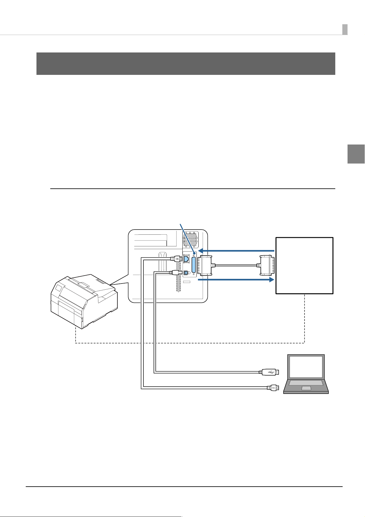
External I/O (D-Sub25 pin)
Input signal
(Control of the printer)
Output signal
(Check the printer status)
Synchronize
USB or Ethernet (Used to transmit commands)
External device
Overview
This guide describes the external I/O specifications for the CW-C6000 Series/CW-C6500 Series. Please develop
your device to match these specifications.
Functionality
Using the external I/O signal allows the user to perform synchronous control of the printer and external devices
and to check the printer status.
Signal transmission between the printer and external device uses a D-Sub 25 cable.
Also, use a USB cable or Ethernet cable to send commands, which set the operation for the external I/O, from
the host PC.
System structure
1
A system using the external I/O can be structured as follows.
7
Page 8

External device
The following external devices can be connected.
• Automatic application machine
• Roll rewinder
• Devices that must sync with the printer other than the above
The number of possible connections is one.
Q NOTE
8
Page 9
External I/O Specification
This section describes the external I/O for the printer.
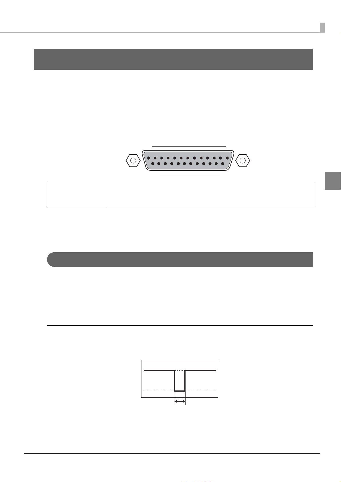
Connector
The external I/O connectors are as follows.
D-sub25 connector (female connector)
Screws: Metric screws
13 1
25 14
Chapter 2 External I/O Specification
Be sure to use the screws to affix the connection cable and ensure the cable does not fall out.
Q NOTE
Signal Definitions
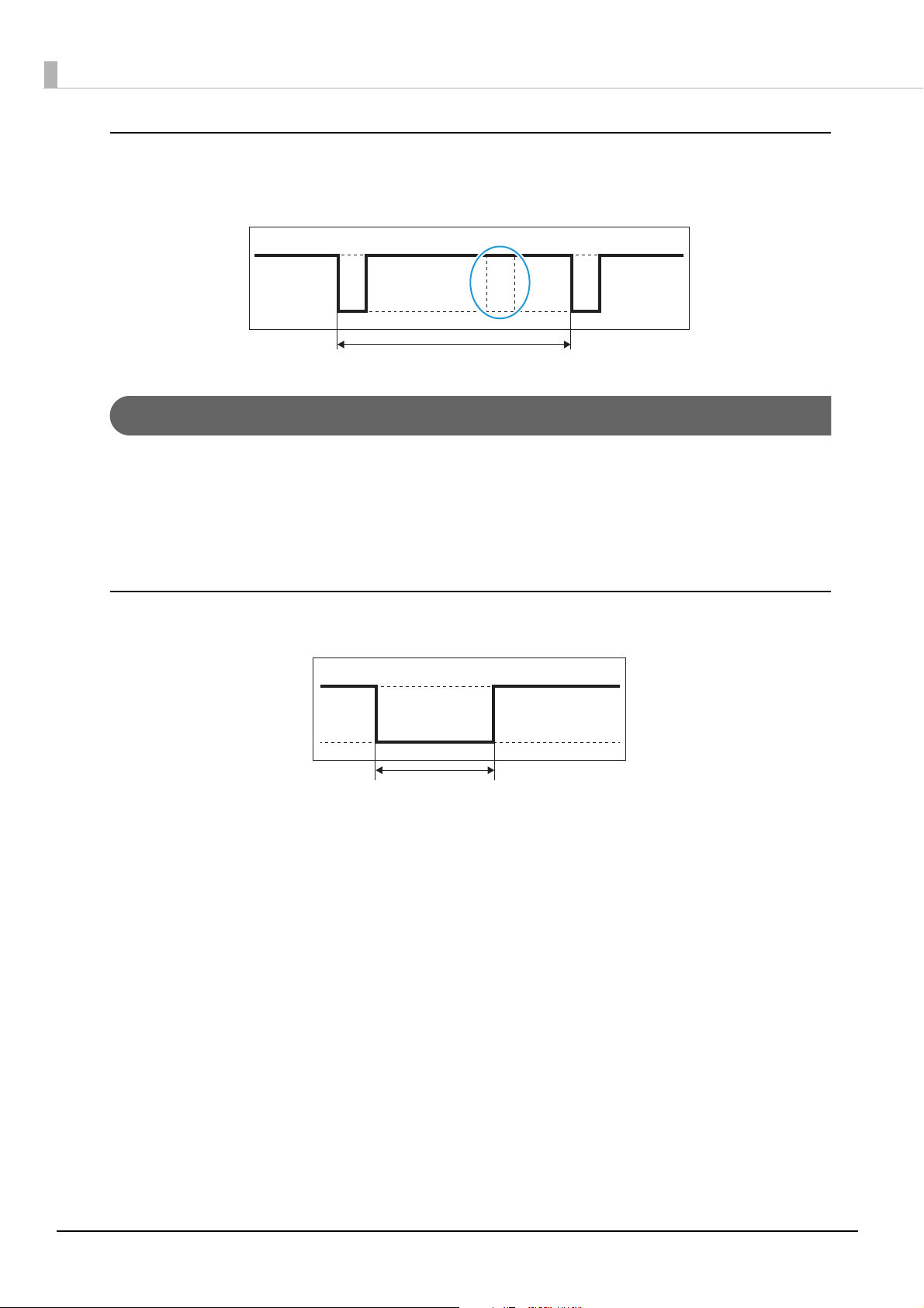
Pulse signal
A pulse signal is a square wave with a fixed short-term width. A low active pulse is a signal that changes sharply
from High to Low, maintains a low state for a short period of time, and then sharply changes back to High. A
High active pulse is a signal that changes sharply from Low to High, maintains a High state for a short period of
time, and then sharply changes back to Low.
If a pulse signal meets the specification for pulse width, the time for the pulse width does not matter.
Pulse width of input signal
As shown in below, input pulse signals that can be received must have a pulse width of 20 msec or more.
Input signals with a pulse width less than 20 ms are not detected.
2
Min. 20 msec
9
Page 10
Minimum interval between input pulse signals
Min. 50 msec
Not detected
Min. 30 msec
As shown below, the interval between input pulse signals that can be received should be 50 ms or more.
If pulse signals are received at an interval of less than 50 ms, the second pulse signal will not be detected.
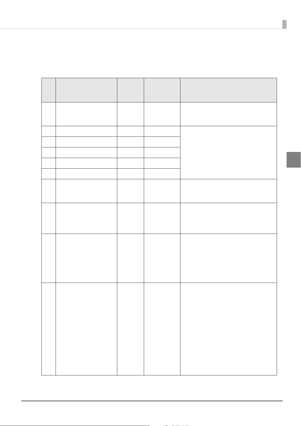
Level signal
A level signal is a signal that maintains a Low and/or High state for a certain length of time, and refers to the
time during which that state is maintained. A Low active level signal changes from High to Low, and the time
during which it maintains the Low state is the active state. A High active level signal changes from Low to High,
and the time during which it maintains the High state is the active state. If both Low and High are significant,
both the Low state and the High state are each maintained for a certain length of time.
Minimum time input level signals that can be received are maintained
As shown below, input level signals that can be received must be maintained for 30 msec or more.
10
Page 11
Chapter 2 External I/O Specification
Pin Assignment and Specification for I/O Signals
The pin assignment and specification for I/O signals are shown below.
Perform settings so that the specifications of the printer and external device match.
Input-
Pin Signal
1 Signal Ground - - Ground for I/O signals.
2 Reserved - - This signal is reversed for the system.
3 Reserved - -
4 Reserved - -
Output
*1
Pulse/Level Description
Set a jumper on CN100 to keep Signal Ground
and Frame Ground separate.
5 Reserved - -
6 Reserved - -
7 Signal Ground - - Ground for I/O signals.
Set a jumper on CN100 to keep Signal Ground
and Frame Ground separate.
8Ink Low
9 IO Power - - Provides 5 V (±10 %) power supply to external
10 Start print
*2
*4
Output Level Indicates whether the printer is in an ink low
state.
• L: Ink low
• H: No ink low
devices.
The maximum current that can be provided is
180 mA.
Set a jumper on CN200 to provide an external I/
O power supply, while also keeping Signal
Ground and Frame Ground separate.
Input Pulse/Level Sends an instruction to start printing.
• In pulse mode, printing starts if a change from
High to Low is detected. Detection occurs
only when the state of the "End print" signal is
High, and does not occur while printing is in
progress.
To print a new label, first return the signal to
High, and then change it again from High to
Low.
• In level mode, printing starts if this signal is
Low. Detection occurs only when the state of
the "End print" signal is High. Printing of new
labels will continue until Low is detected.
• Signal logic: Low active
2
11
Page 12
Pin Signal
Input-
Output
*1
Pulse/Level Description
11 Feed
12 Pause
*3
*3
13 Re-print
Input Level Sends an instruction to feed the paper.
• When the printer is in the Ready or Pause
state, the printer feeds paper if this signal is
Low.
• For labels, if this signal changes to High while
the printer is feeding paper, feeding will stop
when the edge of the next label is detected.
• For continuous paper, if this signal changes to
High while the printer is feeding paper,
feeding will stop after the detection time has
elapsed.
• Signal logic: Low active
Input Pulse Sends an instruction to pause the printer.
• The printer is paused if a change from High to
Low is detected.
• While the printer is paused, if a change from
High to Low is detected again, the printer will
be unpaused.
• Signal logic: Low active
*3
Input Pulse If the label reprinting function is enabled, an
instruction to reprint the label that was last
printed is sent from an external device.
• The label is reprinted if a change from High to
Low is detected.
• Signal logic: Low active
14 Clogged nozzle check
15 Head Cleaning
16 Warning
17 Error
*2
*3
*2
*3 *5
Input Pulse Sends an instruction to check the head for a
clogged nozzle.
• The head is checked for a clogged nozzle if a
change from High to Low is detected.
• Signal logic: Low active
Input Pulse Sends an instruction for head cleaning.
• The head is cleaned if a change from High to
Low is detected.
• Signal logic: Low active
Output Level Indicates whether the printer is in a warning
state.
• L: Warning
• H: No warning
Output Level Indicates whether the printer is in an error state.
• L: Error
• H: No error
12
Page 13
Pin Signal
Input-
Output
*1
Chapter 2 External I/O Specification
Pulse/Level Description
18 End print
*2 *4
Output Pulse/Level The meaning of this signal varies depending on
the values that are set for end print signal mode,
as indicated below.
• Mode 0:
End print signal OFF (End print signal not
output)
• Mode 1:
Indicates that the printer feeds paper during
Low.
• Mode 2:
Indicates that the printer feeds paper during
High.
• Mode 3 (default):
Indicates that, for a pulse with a Low duration
of 20 msec, printing ends and the printer
feeds paper to the predetermined position.
• Mode 4:
Indicates that, for a pulse with a High
duration of 20 msec, printing ends and the
printer feeds paper to the predetermined
position.
* Refer to
page 47
back feeding is included when feeding paper.
"Basic Timing for Label Printing" on
for more information about whether
2
19 Printer ready
20 Reserved - - This signal is reversed for the system.
21 Head maintenance
22 Ink cartridge exchange
23 Data ready
*2
*2
*2
*2
Output Level Indicates whether the printer is in the ready
state.
• L: Ready
• H: Not Ready
Output Level Indicates whether the printer is undergoing
head maintenance. During head maintenance,
the printer is undergoing either a nozzle check
or head cleaning.
• L: Head maintenance in progress
• H: Head maintenance not in progress
Output Level Indicates whether the printer requires an ink
cartridge exchange.
• L: Ink cartridge exchange required
• H: Ink cartridge exchange not required
Output Level Indicates that the generation of print data has
completed in the printer.
• L: Print data preparation complete
• H: Print data preparation not complete
13
Page 14
Pin Signal
Input-
Output
*1
Pulse/Level Description
24 Clogged nozzle detected
25 Paper out
*2
*2 *5
Output Level Indicates whether the printer has detected a
clogged nozzle in the head.
• L: Clogged nozzle detected
• H: Clogged nozzle not detected
* The results of the previous nozzle check are
applied.
* Even if nozzle clogging is not specified (when
a nozzle check is not performed, or if a warning occurs while the state of the nozzles is
unclear), the value at that time is maintained.
Output Level Indicates whether the printer is in a paper out
state.
• L: Paper out
• H: No paper out
∗1 Input and output directions are described as viewed from the printer.
Input: Signal input to the printer from an external device.
Output: Signal output from the printer to an external device.
∗2 The logic for all output signals can be reversed.
The information provided in the Description column is based on the default signal logic.
If the signal logic is reversed, it will be the opposite.
∗3 Except for the "Start print" signal, the logic for all input signals is low active. (The logic for input signals cannot be
reversed.)
∗4 The "Start print" signal and "End print" signal can be switched between pulse and level. Therefore, there are 4
possible configurations for the "End print" signal: [Pulse or Level] x [Low Active or High Active].
∗5 The results of the previous nozzle check are applied to the clogged nozzle detected signal (pin 24). Therefore,
during a nozzle check, issue a nozzle check command (pin 14) before checking the clogged nozzle detected signal
(pin 24). Refer to timing "Timing" on page 47
.
14
Page 15
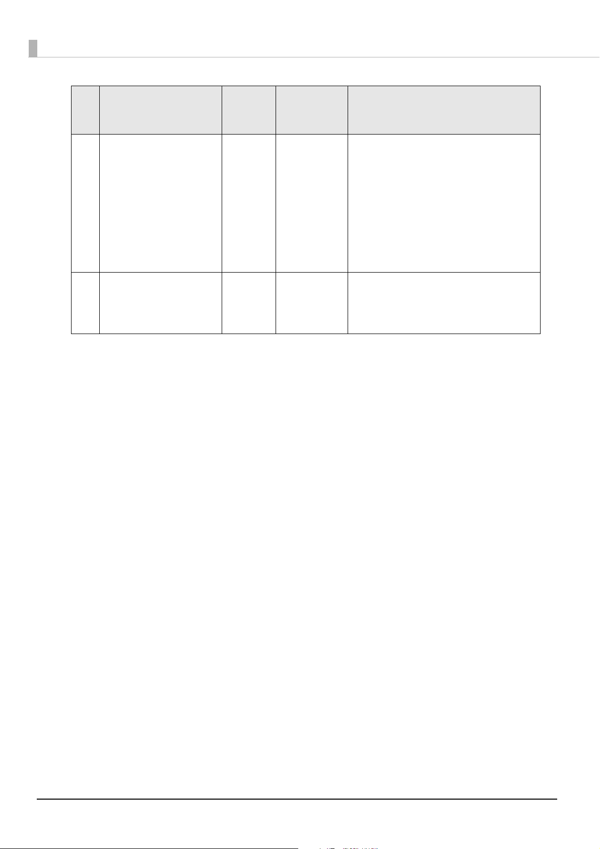
Specification for I/O Signals
Printer side External device side
External device
output
Printer input
This section describes the I/O signal specifications.
Input/Output Item Value
Chapter 2 External I/O Specification
Input signal to the printer Type of output port on the
external device
Low level VIL_max. 0.8 V
High level Sink current (leakage current) Max. 10 uA
Output signal from printer Type of output port on the
printer
Low level VOL_max. 0.8 V
High level VOH_min. 4.0 V
Open drain or open collector output
Sink current Min. 2 mA
Max. 7 mA
Open collector output (pull-up resistor is on the
printer)
Allowable sink current Max. 1.8 mA
*3
*1
*2
∗1 The sink current is limited by the current limiting resistance (R = 1 kΩ).
∗2 Do not use this as a drive for a high-current load such as a coil.
∗3 This depends on the pull-up resistance (Rpu = 10k ohm) of the printer and the input resistance of the external
device.
Regardless of whether an external device is connected or the connected external device is
CAUTION
turned on or off, when the printer is turned on, the power supply voltage and signal are output
from the I/O power supply pin and output signal pin of the external I/O connector. Connect an
external device under this assumption.
2
Example input signal circuit
+5 V
R
FGSG SG
15
Page 16
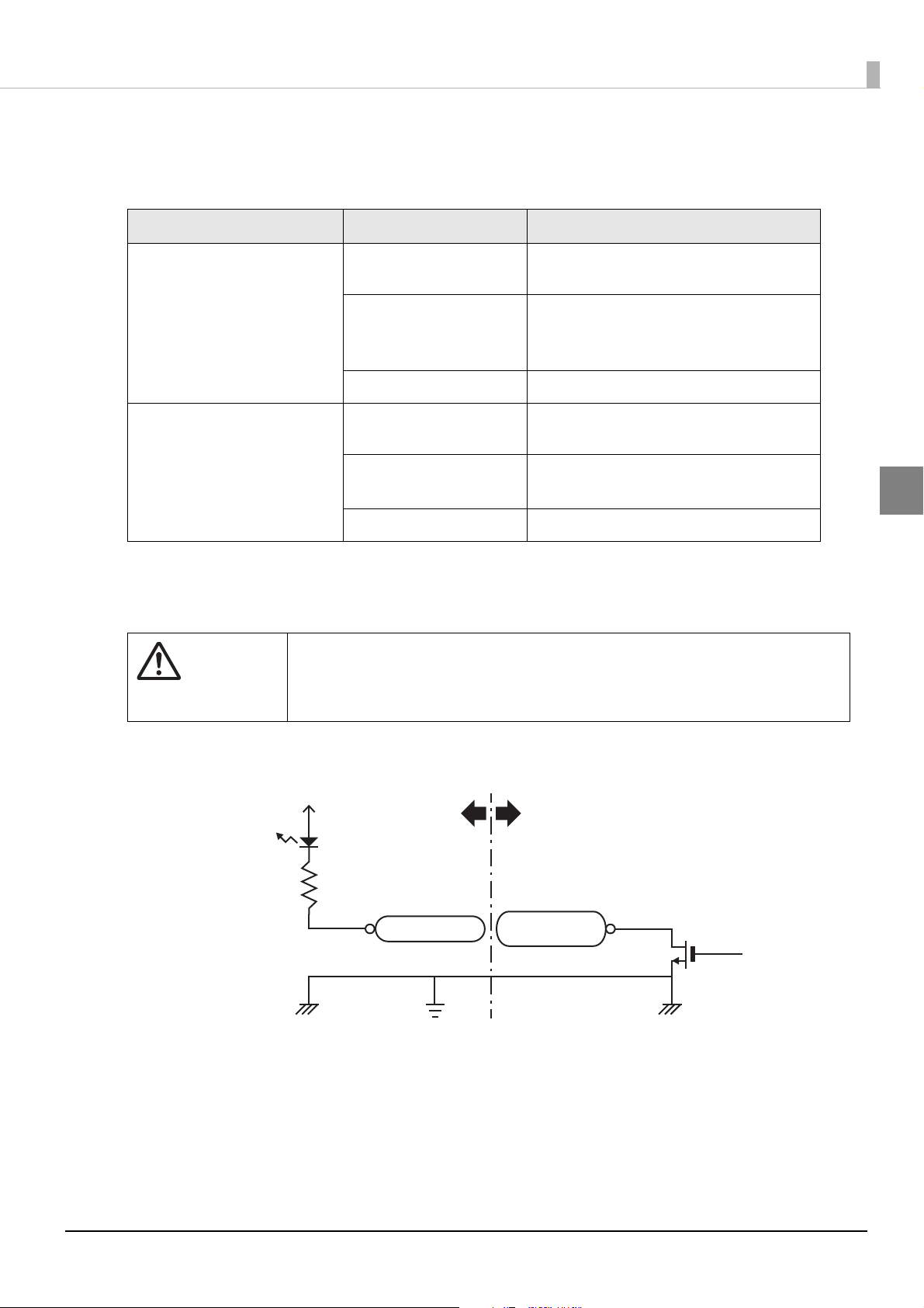
Example output signal circuit
Printer side External device side
External device
input
Printer output
+5 V
Rpu
FGSG SG
16
Page 17

Chapter 3 Commands
Commands
This section describes the commands of the external I/O. You can acquire each signal's mode settings and
printer setting values.
List of Commands
The signal specifications for the external I/O are as follows.
No.
1External I/O out-
2 Data ready signal mode setting ^S(CNA,A,c
3 Clogged nozzle detected signal
Command
name category
put signal settings
Command function Command and parameters
End print signal mode setting ^S(CNA,B,c
c = D/E/N/0 - 4
0/D: End print signal OFF (End print signal not
1: Normal: High, When feeding paper: Low
2/E: Normal: Low, When feeding paper: High
3: Normal: High, For 20 msec after printing:
4/N: Normal: Low, For 20 msec after printing:
c= D/E/0/1/2
0/D: Off
1: Normal: High, When an event occurs: Low
2/E: Normal: Low, When an event occurs: High
^S(CNA,D,c
mode setting
c= D/E/0/1/2
0/D: Off
1: Normal: High, When an event occurs: Low
2/E: Normal: Low, When an event occurs: High
output)
Low
High
3
4 Head maintenance mode setting ^S(CNA,M,c
c= D/E/0/1/2
0/D: Off
1: Normal: High, When an event occurs: Low
2/E: Normal: Low, When an event occurs: High
5 Printer ready signal mode setting ^S(CNA,O,c
c= D/E/0/1/2
0/D: Off
1: Normal: High, When an event occurs: Low
2/E: Normal: Low, When an event occurs: High
6 Warning signal mode setting ^S(CNA,W,c
c= D/E/0/1/2
0/D: Off
1: Normal: High, When an event occurs: Low
2/E: Normal: Low, When an event occurs: High
17
Page 18
No.
Command
name category
Command function Command and parameters
7External I/O out-
put signal settings
8 Ink low signal mode setting ^S(CNA,J,c
9 Ink cartridge exchange signal
10 Paper out signal mode setting ^S(CNA,P,c
Error signal mode setting ^S(CNA,E,c
c= D/E/0/1/2
0/D: Off
1: Normal: High, When an event occurs: Low
2/E: Normal: Low, When an event occurs: High
c= D/E/0/1/2
0/D: Off
1: Normal: High, When there is little ink
2/E: Normal: Low, When there is little ink
^S(CNA,I,c
mode setting
c= D/E/0/1/2
0/D: Off
1: Normal: High, When ink must be
2/E: Normal: Low, When ink must be replaced:
c= D/E/0/1/2
0/D: Off
1: Normal: High, When there is no paper:
2/E: Normal: Low, When there is no paper:
remaining: Low
remaining: High
replaced: Low
High
Low
High
18
Page 19
Chapter 3 Commands
No.
11 External I/O input
12 Head cleaning signal mode
13 Clogged nozzle check signal mode
14 Feed signal mode setting ^S(CNI,F,c
Command
name category
signal settings
Command function Command and parameters
Pause signal mode setting ^S(CNI,P,c
c= 0/1
0: Ignore pause signal.
1: Switch the pause state if Low is asserted
^S(CNI,C,c
setting
setting
c= 0/1
0: Ignore cleaning signal.
1: Clean if Low is asserted for the cleaning
^S(CNI,D,c
c= 0/1
0: Ignore clogged nozzle check signal.
1: Check for clogged nozzle if Low is
c= 0/3
0: Ignore feed label signal.
1: Continue feeding the label as long as Low
for the pause signal for 20 msec or longer.
signal for 20 msec or longer.
asserted for the clogged nozzle check signal for 20 msec or longer.
3
is asserted.
15 Mode setting for start print signal ^S(CNI,S,c
c= 0/1/3
0: Ignore start print signal. (Normal print
1: Issue a label if Low is asserted for the start
3: Continue issuing labels as long as Low is
16 Mode setting for re-print signal ^S(CNI,R,c
c= 0/1
0: Ignore reprint label signal.
1: Reprint the previously printed label if Low
mode in which the printer receives and
prints data, without using the start print
signal input to the external I/O.)
print signal for 20 msec or longer.
asserted for the start print signal.
is asserted for the reprint label signal for
20 msec or longer.
19
Page 20

No.
Command
name category
Command function Command and parameters
17 Acquisition of
setting values for
18 Acquisition of mode setting values
19 Acquisition of mode setting values
20 Acquisition of mode setting values
21 Acquisition of mode setting values
22 Acquisition of mode setting values
23 Acquisition of mode setting values
24 Acquisition of mode setting value
25 Acquisition of mode setting value
external I/O output
signal
Acquisition of mode setting values
for end print signal
for data ready signal
for clogged nozzle detected signal
for head maintenance signal
for printer ready signal
for warning signal
for error signal
for ink low signal
for ink cartridge exchange signal
~H(CNA,B
~H(CNA,A
~H(CNA,D
~H(CNA,M
~H(CNA,O
~H(CNA,W
~H(CNA,E
~H(CNA,J
~H(CNA,I
26 Acquisition of mode setting value
for paper out signal
27 Acquisition of
setting values for
28 Acquisition of setting values for
29 Acquisition of setting values for
30 Acquisition of setting values for
31 Acquisition of setting values for
32 Acquisition of setting values for
external I/O input
signal
Acquisition of setting values for
pause signal
head cleaning signal
clogged nozzle check signal
feed signal
start print signal
re-print signal
~H(CNA,P
~H(CNI,P
~H(CNI,C
~H(CNI,D
~H(CNI,F
~H(CNI,S
~H(CNI,R
20
Page 21

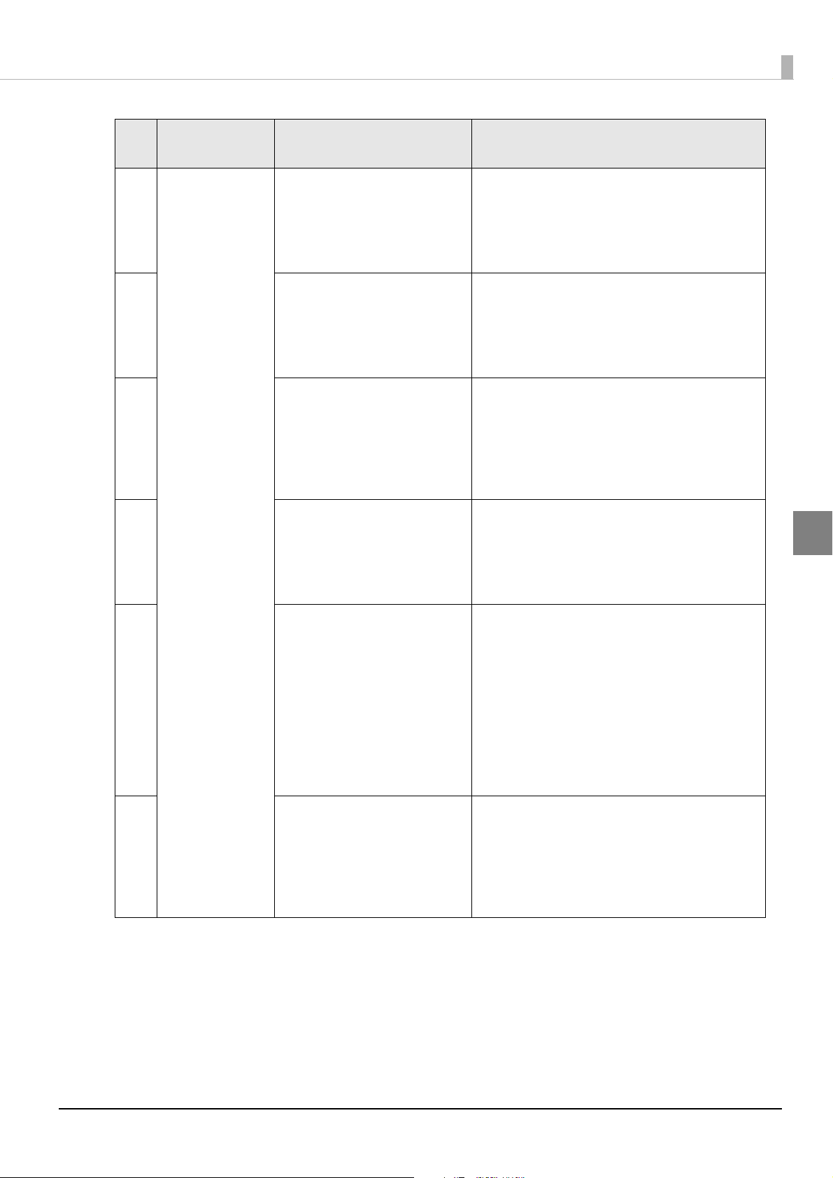
Setting Commands
Signal
Data preparation
complete
Start print
End print
Printer status
Sent label
format
Processed
label format
Standby for
start signal
Print label
Ready to print
next label
Signal status
Preparing
Preparation
complete
Do not start
Start
Not finished
Finished
This section describes the commands for setting the external I/O.
End print signal (output) mode settings
[Format]
^S(CNA,B,c
[Parameter] c
Description Definition range
c = Mode setting D/E/N/0/1/2/3/4
[Function]
Configure the mode settings for the end print signal.
Value for parameter c Description
Chapter 3 Commands
D/0 Turn the end print signal OFF. (End print signal not output)
1 Set the end print signal (pin 18) as follows: Normal: High,
When feeding paper: Low.
E/2 Set the end print signal (pin 18) as follows: Normal: Low,
When feeding paper: High.
3 Set the end print signal (pin 18) as follows: Normal: High,
When continuous printing ends and the printer stops at the predetermined position: Low
for 20 msec.
N/4 Set the end print signal (pin 18) as follows: Normal: Low,
When continuous printing ends and the printer stops at the predetermined position: High
for 20 msec.
[Initial value]
0
[Signal timing]
<Mode 1>
3
21
Page 22

<Mode 2>
Signal
Data preparation
complete
Start print
End print
Printer status
Sent label
format
Processed
label format
Standby for
start signal
Print label
Ready to print
next label
Signal status
Preparing
Preparation
complete
Do not start
Start
Not finished
Finished
Signal
Data preparation
complete
Start print
End print
Printer status
Sent label
format
Processed
label format
Standby for
start signal
Print label
Ready to print
next label
Signal status
Preparing
Preparation
complete
Do not start
Start
Not finished
Finished
Signal
Data preparation
complete
Start print
End print
Printer status
Sent label
format
Processed
label format
Standby for
start signal
Print label
Ready to print
next label
Signal status
Preparing
Preparation
complete
Do not start
Start
Not finished
Finished
<Mode 3>
<Mode 4>
[Examples of command transmissions]
Set the end print signal to "Normal: High, When feeding paper: Low".
The ^JUS command must be used to save the settings to the non-volatile memory in the printer.
An example of the command transmission is shown below. It is sent via USB or Ethernet from the computer.
22
^XA
^S(CNA,B,1
^JUS
^XZ
Page 23

Chapter 3 Commands
Mode setting for data ready signal (output)
[Format]
^S(CNA,A,c
[Parameter] c
Description Definition range
c = Mode setting D/E/0/1/2
[Function]
Configure the mode setting for the print data preparation complete (print data deployed) signal.
Value for parameter c Description
D/0 Turn the data ready signal (pin 23) OFF (not output).
1 Set the data ready signal (pin 23) as follows:
Normal: High, When print data preparation is complete: Low.
E/2 Set the data ready signal (pin 23) as follows:
Normal: Low, When print data preparation is complete: High.
[Initial value]
0
[Examples of command transmissions]
Set the data ready signal to "Normal: High, When print data preparation is complete: Low".
The ^JUS command must be used to save the settings to the non-volatile memory in the printer.
An example of the command transmission is shown below. It is sent via USB or Ethernet from the computer.
^XA
^S(CNA,A,1
^JUS
^XZ
3
23
Page 24

Mode setting for clogged nozzle detected signal (output)
[Format]
^S(CNA,D,c
[Parameter] c
Description Definition range
c = Mode setting D/E/0/1/2
[Function]
Configure the mode setting for the clogged nozzle detected signal.
Value for parameter c Description
D/0 Turn the clogged nozzle detected signal (pin 24) OFF (not output).
1 Set the clogged nozzle detected signal (pin 24) as follows: Normal: High, When nozzle
clogged: Low.
E/2 Set the clogged nozzle detected signal (pin 24) as follows: Normal: Low, When nozzle
clogged: High.
[Initial value]
0
[Examples of command transmissions]
Set the clogged nozzle detected signal to "Normal: High, When nozzle clogged: Low".
The ^JUS command must be used to save the settings to the non-volatile memory in the printer.
An example of the command transmission is shown below. It is sent via USB or Ethernet from the computer.
^XA
^S(CNA,D,1
^JUS
^XZ
24
Page 25

Mode setting for head maintenance signal (output)
[Format]
^S(CNA,M,c
[Parameter] c
Description Definition range
c = Mode setting D/E/0/1/2
[Function]
Configure the mode setting for the head maintenance signal.
Value for parameter c Description
D/0 Turn the head maintenance signal (pin 21) OFF (not output).
1 Set the head maintenance signal (pin 21) as follows:
Normal: High, When head maintenance is in progress: Low.
Chapter 3 Commands
E/2 Set the head maintenance signal (pin 21) as follows:
Normal: Low, When head maintenance is in progress: High.
[Initial value]
0
[Examples of command transmissions]
Set the head maintenance signal to "Normal: High, When head maintenance is in progress: Low".
The ^JUS command must be used to save the settings to the non-volatile memory in the printer.
An example of the command transmission is shown below. It is sent via USB or Ethernet from the computer.
^XA
^S(CNA,M,1
^JUS
^XZ
3
25
Page 26

Mode setting for printer ready signal (output)
[Format]
^S(CNA,O,c
[Parameter] c
Description Definition range
c = Mode setting D/E/0/1/2
[Function]
Configure the mode settings for the printer ready signal.
Value for parameter c Description
D/0 Turn the printer ready signal (pin 19) OFF (not output).
1 Set the printer ready signal (pin 19) as follows: Normal: High, When printer is ready: Low.
E/2 Set the printer ready signal (pin 19) as follows: Normal: Low, When printer is ready: High.
[Initial value]
0
[Examples of command transmissions]
Set the printer ready signal to "Normal: High, When printer is ready: Low".
The ^JUS command must be used to save the settings to the non-volatile memory in the printer.
An example of the command transmission is shown below. It is sent via USB or Ethernet from the computer.
^XA
^S(CNA,O,1
^JUS
^XZ
26
Page 27

Chapter 3 Commands
Mode setting for warning signal (output)
[Format]
^S(CNA,W,c
[Parameter] c
Description Definition range
c = Mode setting D/E/0/1/2
[Function]
Configure the mode settings for the warning signal.
Value for parameter c Description
D/0 Turn the warning signal (pin 16) OFF (not output).
1 Set the warning signal (pin 16) as follows: Normal: High, When a warning occurs: Low.
E/2 Set the warning signal (pin 16) as follows: Normal: Low, When a warning occurs: High.
[Initial value]
0
[Examples of command transmissions]
Set the warning signal to "Normal: High, When a warning occurs: Low".
The ^JUS command must be used to save the settings to the non-volatile memory in the printer.
An example of the command transmission is shown below. It is sent via USB or Ethernet from the computer.
^XA
^S(CNA,W,1
^JUS
^XZ
3
27
Page 28

Mode setting for error signal (output)
[Format]
^S(CNA,E,c
[Parameter] c
Description Definition range
c = Mode setting D/E/0/1/2
[Function]
Configure the mode settings for the error signal.
Value for parameter c Description
D/0 Turn the error signal (pin 17) OFF (not output).
1 Set the error signal (pin 17) as follows: Normal: High, When an error occurs: Low.
E/2 Set the error signal (pin 17) as follows: Normal: Low, When an error occurs: High.
[Initial value]
0
[Examples of command transmissions]
Set the error signal to "Normal: High, When an error occurs: Low".
The ^JUS command must be used to save the settings to the non-volatile memory in the printer.
An example of the command transmission is shown below. It is sent via USB or Ethernet from the computer.
^XA
^S(CNA,E,1
^JUS
^XZ
28
Page 29

Chapter 3 Commands
Ink low signal (output) mode setting
[Format]
^S(CNA,J,c
[Parameter] c
Description Definition range
c = Mode setting D/E/0/1/2
[Function]
This sets the ink low signal mode setting.
Value for parameter c Description
D/0 Turns the ink low signal (pin 8) OFF (not output).
1 Sets the ink low signal (pin 8) as follows: Normal: High, When there is little ink remaining:
Low.
E/2 Sets the ink low signal (pin 8) as follows: Normal: Low, When there is little ink remaining:
High.
[Initial value]
0
[Examples of command transmissions]
The ink low signal is set to the mode that is high in the normal status, and low when there is little ink remaining.
The ^JUS command must be used to save the settings to the non-volatile memory in the printer.
An example of the command transmission is shown below. It is sent via USB or Ethernet from the computer.
^XA
^S(CNA,J,1
^JUS
^XZ
3
29
Page 30

Ink cartridge exchange signal (output) mode setting
[Format]
^S(CNA,I,c
[Parameter] c
Description Definition range
c = Mode setting D/E/0/1/2
[Function]
This sets the ink cartridge exchange signal mode setting.
Value for parameter c Description
D/0 Turns the ink cartridge exchange signal (pin 22) OFF (not output).
1 Sets the ink cartridge exchange signal (pin 22) as follows: Normal: High, When ink must be
replaced: Low.
E/2 Sets the ink cartridge exchange signal (pin 22) as follows: Normal: Low, When ink must be
replaced: High.
[Initial value]
0
[Examples of command transmissions]
The ink cartridge exchange signal is set to the mode that is high in the normal status, and low when the ink
must be replaced.
The ^JUS command must be used to save the settings to the non-volatile memory in the printer.
An example of the command transmission is shown below. It is sent via USB or Ethernet from the computer.
^XA
^S(CNA,I,1
^JUS
^XZ
30
Page 31

Chapter 3 Commands
Paper out signal (output) mode setting
[Format]
^S(CNA,P,c
[Parameter] c
Description Definition range
c = Mode setting D/E/0/1/2
[Function]
This sets the paper out signal mode setting.
Value for parameter c Description
D/0 Turns the paper out signal (pin 25) OFF (not output).
1 Sets the paper out signal (pin 25) as follows: Normal: High, When there is no paper: Low.
E/2 Sets the paper out signal (pin 25) as follows: Normal: Low, When there is no paper: High.
[Initial value]
0
[Examples of command transmissions]
The paper out signal is set to the mode that is high in the normal status, and low when there is no paper.
The ^JUS command must be used to save the settings to the non-volatile memory in the printer.
An example of the command transmission is shown below. It is sent via USB or Ethernet from the computer.
^XA
^S(CNA,P,1
^JUS
^XZ
3
31
Page 32

Mode setting for pause signal (input)
[Format]
^S(CNI,P,c
[Parameter] c
Description Definition range
c = Mode setting 0/1
[Function]
Configure the mode settings for the pause signal.
Value for parameter c Description
0 Ignore the pause signal (pin 12).
1 Set the pause signal (pin 12) to the following mode:
Switch to the pause state when a Low signal is input for 20 msec or longer.
[Initial value]
0
[Examples of command transmissions]
Set the pause signal to "Switch to the pause state when a Low signal is input for 20 msec or longer".
The ^JUS command must be used to save the settings to the non-volatile memory in the printer.
An example of the command transmission is shown below. It is sent via USB or Ethernet from the computer.
^XA
^S(CNI,P,1
^JUS
^XZ
32
Page 33

Mode setting for head cleaning signal (input)
[Format]
^S(CNI,C,c
[Parameter] c
Description Definition range
c = Mode setting 0/1
[Function]
Configure the mode settings for the head cleaning signal.
Value for parameter c Description
0 Ignore the head cleaning signal (pin 15).
1 Set the head cleaning signal (pin 15) to the following mode:
Clean the head when a Low signal is input for 20 msec or longer.
Chapter 3 Commands
[Initial value]
0
[Examples of command transmissions]
Set the head cleaning signal to "Clean the head when a Low signal is input for 20 msec or longer".
The ^JUS command must be used to save the settings to the non-volatile memory in the printer.
An example of the command transmission is shown below. It is sent via USB or Ethernet from the computer.
^XA
^S(CNI,C,1
^JUS
^XZ
3
33
Page 34

Mode setting for clogged nozzle check signal (input)
[Format]
^S(CNI,D,c
[Parameter] c
Description Definition range
c = Mode setting 0/1
[Function]
Configure the mode setting for the clogged nozzle check signal.
Value for parameter c Description
0 Ignore the clogged nozzle check signal (pin 14).
1 Set the clogged nozzle check signal (pin 14) to the following mode:
Check the nozzles when a Low signal is input for 20 msec or longer.
[Initial value]
0
[Examples of command transmissions]
Set the clogged nozzle signal to "Check the nozzles when a Low signal is input for 20 msec or longer".
The ^JUS command must be used to save the settings to the non-volatile memory in the printer.
An example of the command transmission is shown below. It is sent via USB or Ethernet from the computer.
^XA
^S(CNI,D,1
^JUS
^XZ
34
Page 35

Mode setting for feed signal (input)
[Format]
^S(CNI,F,c
[Parameter] c
Description Definition range
c = Mode setting 0/3
[Function]
Configure the mode settings for the feed signal.
Value for parameter c Description
0 Ignore the feed signal (pin 11).
3 Set the feed signal (pin 11) to the following mode:
Feed the label as long as a Low signal is input.
Chapter 3 Commands
[Initial value]
0
[Examples of command transmissions]
Set the feed signal to "Feed the label as long as a Low signal is input".
The ^JUS command must be used to save the settings to the non-volatile memory in the printer.
An example of the command transmission is shown below. It is sent via USB or Ethernet from the computer.
^XA
^S(CNI,F,3
^JUS
^XZ
3
35
Page 36

Mode setting for start print signal (input)
[Format]
^S(CNI,S,c
[Parameter] c
Description Definition range
c = Mode setting 0/1/3
[Function]
Configure the mode settings for the start print signal.
Value for parameter c Description
0 Ignore the start print signal (pin 10).
(Normal print mode in which the printer receives and prints data, without using the start
print signal input to the external I/O.)
1 Set the start print signal (pin 10) to the following mode:
Print labels when a Low signal is input for 20 msec or longer.
3 Set the start print signal (pin 10) to the following mode:
Print labels as long as a Low signal is input.
[Initial value]
0
[Examples of command transmissions]
Set the start print signal to "Print labels when a Low signal is input for 20 msec or longer".
The ^JUS command must be used to save the settings to the non-volatile memory in the printer.
An example of the command transmission is shown below. It is sent via USB or Ethernet from the computer.
^XA
^S(CNI,S,1
^JUS
^XZ
36
Page 37

Chapter 3 Commands
Mode setting for re-print signal (input)
[Format]
^S(CNI,R,c
[Parameter] c
Description Definition range
c = Mode setting 0/1
[Function]
Configure the mode settings for the re-print signal.
Value for parameter c Description
0 Ignore the re-print signal (pin 13).
1 Set the re-print signal (pin 13) to the following mode: Reprint the previously printed label
when a Low signal is input for 20 msec or longer.
[Initial value]
0
[Examples of command transmissions]
Set the re-print signal to "Reprint labels when a Low signal is input for 20 msec or longer".
The ^JUS command must be used to save the settings to the non-volatile memory in the printer.
An example of the command transmission is shown below. It is sent via USB or Ethernet from the computer.
^XA
^S(CNI,R,1
^JUS
^XZ
3
37
Page 38

Acquisition Commands for Setting Values
This section describes the commands for acquiring setting values of the printer.
Acquisition commands for mode setting values for end print signal (output)
[Format]
~H(CNA,B
[Parameter] None
[Function]
Acquire the mode setting values for the end print signal.
Return value after
executing this command
0 End print signal OFF (End print signal not output)
1 End print signal (pin 18) set to Normal: High, When feeding paper: Low
2 End print signal (pin 18) set to Normal: Low, When feeding paper: High
3 End print signal (pin 18) set to Normal: High, When continuous printing ends and the
printer stops at the predetermined position:
Low for 20 msec.
4 End print signal (pin 18) set to Normal: Low, When continuous printing ends and the
printer stops at the predetermined position:
High for 20 msec.
Description
Acquisition commands for mode setting values for data ready signal (output)
[Format]
~H(CNA,A
[Parameter] None
[Function]
Acquire the mode setting values for the print data preparation complete (print data deployed) signal.
Return value after
executing this command
0 Data ready signal (pin 23) OFF (not output).
1 Data ready signal (pin 23) set to Normal: High,
When print data preparation is complete: Low
2 Data ready signal (pin 23) set to Normal: Low,
When print data preparation is complete: High
38
Description
Page 39

Chapter 3 Commands
Acquisition commands for mode setting values for clogged nozzle detected signal (output)
[Format]
~H(CNA,D
[Parameter] None
[Function]
Acquire the mode setting values for the clogged nozzle detected signal.
Return value after
executing this command
0 Clogged nozzle detected signal (pin 24) OFF (not output)
1 Clogged nozzle detected signal (pin 24) set to Normal: High,
When nozzle clogged: Low
2 Clogged nozzle detected signal (pin 24) set to Normal: Low,
When nozzle clogged: High
Description
Acquisition commands for mode setting values for head maintenance signal (output)
[Format]
~H(CNA,M
[Parameter] None
[Function]
Acquire the mode setting values for the head maintenance signal.
Return value after
executing this command
Description
3
0 Head maintenance signal (pin 21) OFF (not output)
1 Head maintenance signal (pin 21) set to Normal: High,
When head maintenance is in progress: Low
2 Head maintenance signal (pin 21) set to Normal: Low,
When head maintenance is in progress: High
39
Page 40

Acquisition commands for mode setting values for printer ready signal (output)
[Format]
~H(CNA,O
[Parameter] None
[Function]
Acquire the mode setting values for the printer ready signal.
Return value after
executing this command
0 Printer ready signal (pin 19) OFF (not output)
1 Printer ready signal (pin 19) set to Normal: High, When printer is ready: Low
2 Printer ready signal (pin 19) set to Normal: Low, When printer is ready: High
Description
Acquisition commands for mode setting values for warning signal (output)
[Format]
~H(CNA,W
[Parameter] None
[Function]
Acquire the mode setting values for the warning signal.
Return value after
executing this command
0 Warning signal (pin 16) OFF (not output)
Description
1 Warning signal (pin 16) set to Normal: High, When a warning occurs: Low
2 Warning signal (pin 16) set to Normal: Low, When a warning occurs: High
Acquisition commands for mode setting values for error signal (output)
[Format]
~H(CNA,E
[Parameter] None
[Function]
Acquire the mode setting values for the error signal.
Return value after
executing this command
0 Error signal (pin 17) OFF (not output)
1 Error signal (pin 17) set to Normal: High, When an error occurs: Low
2 Error signal (pin 17) set to Normal: Low, When an error occurs: High
Description
40
Page 41

Acquisition of mode setting value for ink low signal (input)
[Format]
~H(CNA,J
[Parameter] None
[Function]
This acquires the mode setting value for the ink low signal.
Chapter 3 Commands
Return value after
executing this command
D/0 Mode in which the ink low signal (pin 8) is OFF (not output)
1 Mode in which the ink low signal (pin 8) is as follows: Normal: High, When there is little
ink remaining: Low
E/2 Mode in which the ink low signal (pin 8) is as follows: Normal: Low, When there is little
ink remaining: High
Description
Acquisition of mode setting value for ink cartridge exchange signal (input)
[Format]
~H(CNA,I
[Parameter] None
[Function]
This acquires the mode setting value for the ink cartridge exchange signal.
Return value after
executing this command
Description
3
D/0 Mode in which the ink cartridge exchange signal (pin 22) is OFF (not output)
1 Mode in which the ink cartridge exchange signal (pin 22) is as follows: Normal: High,
When ink must be replaced: Low
E/2 Mode in which the ink cartridge exchange signal (pin 22) is as follows: Normal: Low,
When ink must be replaced: High
41
Page 42

Acquisition command of mode setting value for paper out signal (input)
[Format]
~H(CNA,P
[Parameter] None
[Function]
This acquires the mode setting value for the paper out signal.
Return value after
executing this command
D/0 Mode in which the paper out signal (pin 25) is OFF (not output)
1 Mode in which the paper out signal (pin 25) is as follows: Normal: High, When there is no
paper: Low
E/2 Mode in which the paper out signal (pin 25) is as follows: Normal: Low, When there is no
paper: High
Description
Acquisition commands for mode setting values for pause signal (input)
[Format]
~H(CNI,P
[Parameter] None
[Function]
Acquire the mode setting values for the pause signal.
Return value after
executing this command
Description
0 Pause signal (pin 12) ignored
1 Pause signal (pin 12) set to switch to the pause state when a Low signal is input for 20
msec or longer
42
Page 43

Chapter 3 Commands
Acquisition commands for mode setting values for head cleaning signal (input)
[Format]
~H(CNI,C
[Parameter] None
[Function]
Acquire the mode setting values for the head cleaning signal.
Return value after
executing this command
0 Head cleaning signal (pin 15) ignored
1 Head cleaning signal (pin 15) set to clean the head when a Low signal is input for 20
msec or longer
Description
Acquisition commands for mode setting values for clogged nozzle check signal (input)
[Format]
~H(CNI,D
[Parameter] None
[Function]
Acquire the mode setting values for the clogged nozzle check signal.
Return value after
executing this command
0 Clogged nozzle check signal (pin 14) ignored
1 Clogged nozzle check signal (pin 14) set to check the nozzles when a Low signal is input
for 20 msec or longer.
Description
3
Acquisition commands for mode setting values for feed signal (input)
[Format]
~H(CNI,F
[Parameter] None
[Function]
Acquire the mode setting values for the feed signal.
Return value after
executing this command
0 Feed signal (pin 11) ignored
1 Feed signal (pin 11) set to feed the label when a Low signal is input for 20 msec or longer
Description
43
Page 44

Acquisition commands for mode setting values for start print signal (input)
[Format]
~H(CNI,S
[Parameter] None
[Function]
Acquire the mode setting values for the start print signal.
Return value after
executing this command
0 Start print signal (pin 10) ignored
1 Start print signal (pin 10) set to print labels when a Low signal is input for 20 msec or lon-
ger
3 Start print signal (pin 10) set to print labels as long as a Low signal is input
Description
Acquisition commands for mode setting values for re-print signal (input)
[Format]
~H(CNI,R
[Parameter] None
[Function]
Acquire the mode setting values for the re-print signal.
Return value after
executing this command
0 Re-print signal (pin 13) ignored
Description
1 Re-print signal (pin 13) set to reprint the previously printed label when a Low signal is
input for 20 msec or longer
44
Page 45
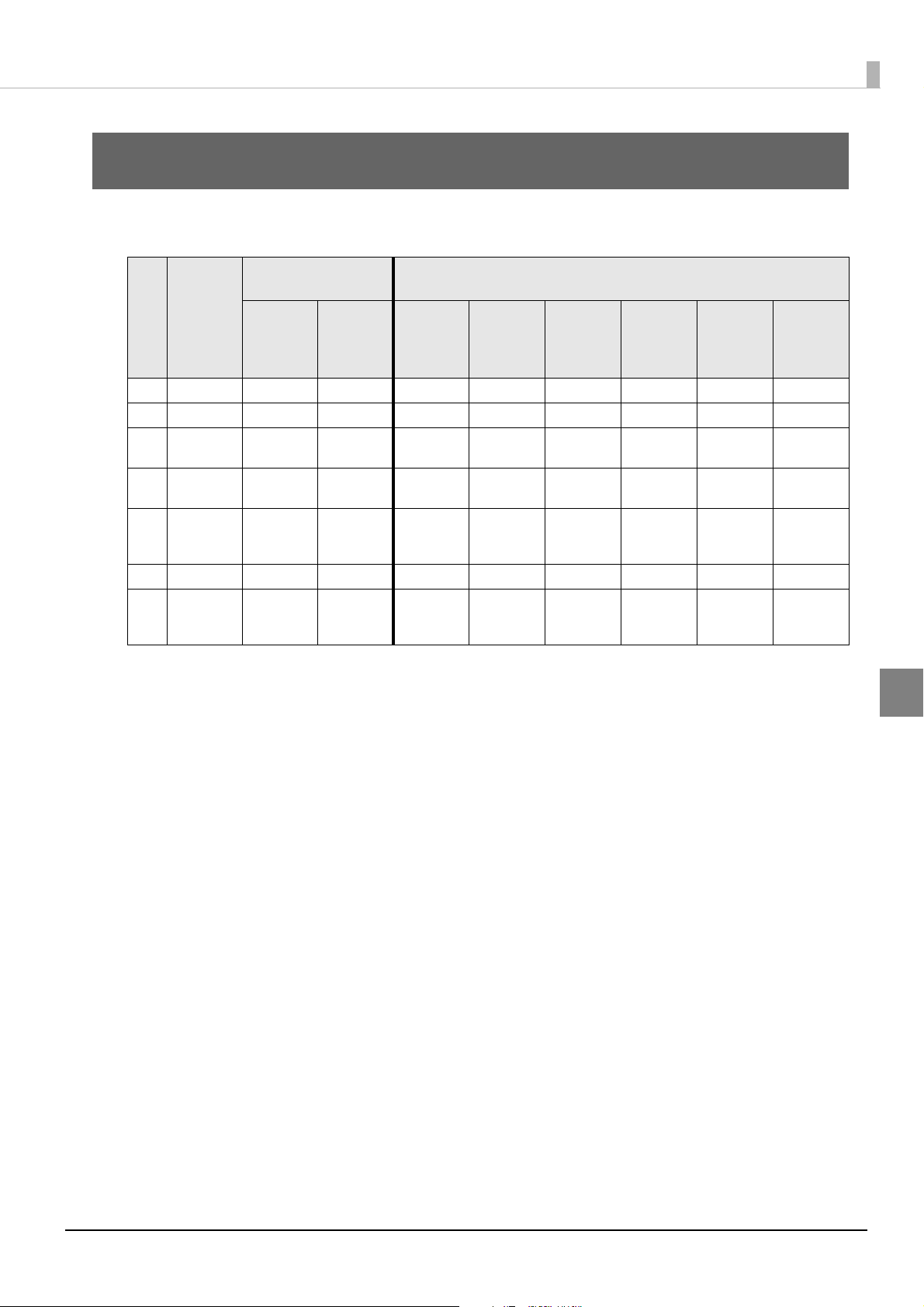
Chapter 4 Printer Statuses and Signals
Printer Statuses and Signals
This section describes the printer statuses, and the relationships between the printer status and the signal.
Signal status and
meaning
Pin Signal
Enable Disable
16 WARNING Warning No Warning - - - - - Warning
17 ERROR Error No Error No Error No Error No Error No Error Error No Error
18 END
PRINT *
19 PRINTER
READY
21 HEAD
MAINTENAN
CE
23 DATA READY Data ready Not ready - - - - - -
24 CLOGGED
NOZZLE
DETECTED
Paper
feeding
Printer ready Printer not
In
maintenance
DetectedNot detected------
Otherwise - Otherwise Paper
ready
Not in
maintenance
Printer not
connected
Printer not
ready
Not in
maintenance
Idling
Printer ready Printer not
Not in
maintenance
Printer status
Mechani-
cal
sequence
running
feeding
ready
Not in
maintenance
Ink
sequence
running
---
Printer not
ready
In
maintenance
Errors Warn ings
Printer not
ready
--
-
∗ When Mode 1 or 2 is set
4
45
Page 46

46
Page 47

Timing
Idling/
waiting
for data
Deploying
data
Printing
Backfeed
Signal
PRINTER
READY
Printer status
DATA READY
START PRINT
END PRINT
Signal
status
Waiting for
printing to
start
Receiving
data
Idling/
waiting
for data
Paper
feeding
Otherwise
Printer ready
Printer not
ready
Data ready
Not ready
This section describes the timing charts for the printer operations and signals.
Basic Timing for Label Printing
The basic timing for label printing is as follows.
Chapter 5 Timing
The pin 18 end print signal is indicated when Mode 1 (= the printer feeds paper during Low) is set, and when
the setting value for the "backfeed operation time settings" menu is "backfeed after label is issued".
5
47
Page 48

Basic Timing for Pausing
Min. 1 sec
Signal
PRINTER
READY
Printer status
DATA READY
START PRINT
END PRINT
Signal
status
Pause
Printing
Receiving
and deploy-
ing data
PrintingPrinting
Paused
Idling/
waiting
for data
Idling/
waiting
for data
Receiving
and deploy-
ing data
Paper
feeding
Otherwise
Printer ready
Printer not
ready
Data ready
Not ready
The basic timing for pausing is as follows.
The pin 10 start print signal is indicated when level mode is set, and the pin 18 end print signal is indicated
when Mode 1 (= the printer feeds paper during Low) is set.
48
Page 49

Chapter 5 Timing
Idling/
waiting
for data
Printing
Backfeed
Signal
PRINTER
READY
Printer status
DATA READY
START PRINT
END PRINT
Signal
status
Move to cut-
ting/peel-
ing position
Idling/
waiting
for data
Receiving
and deploy-
ing data
Printing
Receiving
and deploy-
ing data
Paper
feeding
Otherwise
Printer ready
Printer not
ready
Data ready
Not ready
Idling/
waiting
for data
Printing
Backfeed
Signal
PRINTER
READY
Printer status
DATA READY
START PRINT
END PRINT
Signal
status
Move to cut-
ting/peel-
ing position
Paper
feeding
Otherwise
Idling/
waiting
for data
Receiving
and deploy-
ing data
Printing
Receiving
and deploy-
ing data
Printer ready
Printer not
ready
Data ready
Not ready
Basic Timing for Label Feeding
The timing specification when the setting for the end print signal (pin 18) is Mode 1 or 2 (= signal is asserted
when the printer feeds paper) will vary depending on the setting value for "backfeed operation time settings" in
the printer settings menu.
When "backfeed operation time settings" is set to "backfeed after printing"
The paper feed status is not included during backfeed (the pin 18 end print signal is not asserted during backfeed).
When the end print signal is set to Mode 1 (= the printer feeds paper during Low)
When "backfeed operation time settings" is set to "backfeed before printing"
The paper feed status is included even during backfeed (the pin 18 end print signal is asserted during backfeed).
When the end print signal is set to Mode 1 (= the printer feeds paper during Low)
5
49
Page 50

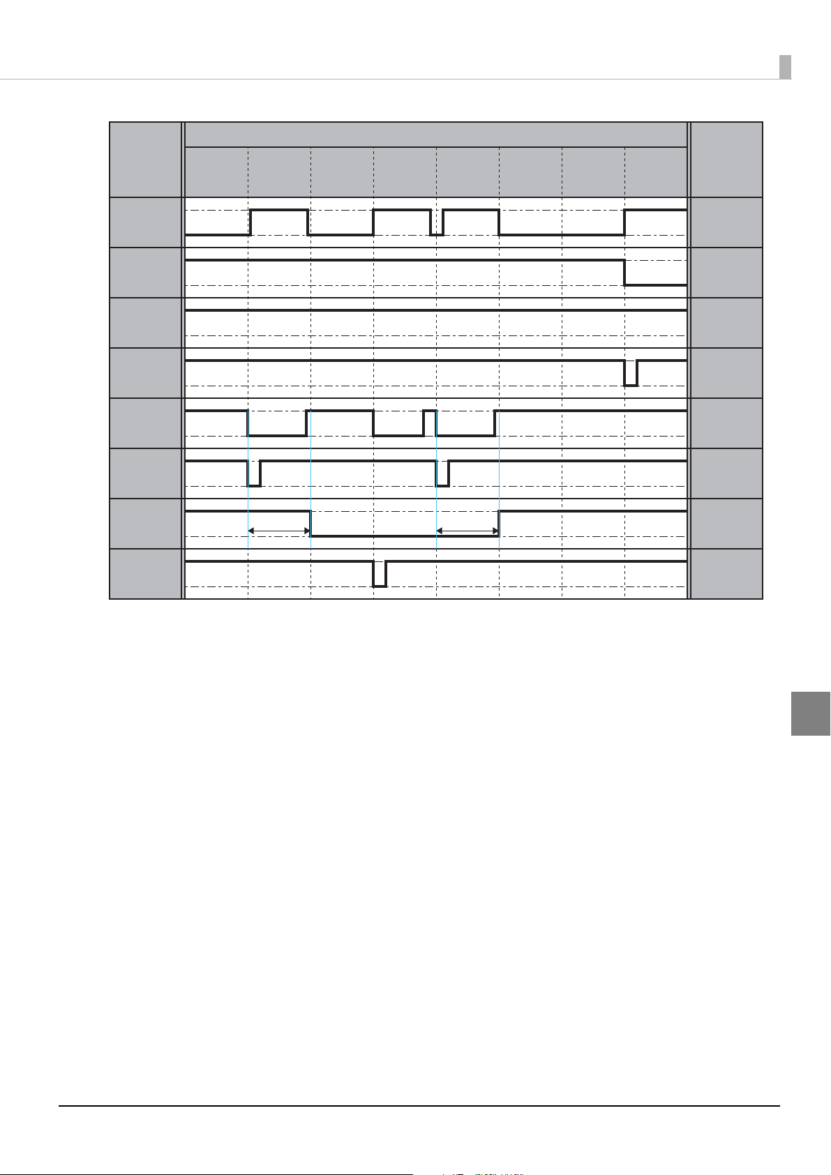
Basic Timing for Nozzle Check and Head Cleaning
The results of the previous nozzle check are applied to the clogged nozzle detected signal.
Nozzle checks are not only executed by the clogged nozzle check signal. They can also be executed automatically in the printer settings.
For this reason, by reading the clogged nozzle detected signal (pin 24) after executing the missing dot check signal, the status of the printer can be detected.
In addition, please check the head maintenance signal (pin 21) to make sure that head maintenance is not in
progress, before transmitting the nozzle check instruction.
The head maintenance signal (pin 21) is asserted during a nozzle check or head cleaning.
The steps from nozzle check through head cleaning are described below.
Check the head maintenance signal to make sure that head maintenance (= nozzle
1
check or head cleaning) is not in progress, and check the error signal to make sure
that an error has not occurred.
Transmit the clogged nozzle check to perform a nozzle check.
2
Check the head maintenance signal to make sure that head maintenance is not in
3
progress, and then check the clogged nozzle detected signal to check for clogged
nozzles.
If a clogged nozzle is discovered in step 3, transmit the head cleaning (pin 15) as nec-
4
essary to perform head cleaning.
If it is unclear whether a nozzle is clogged, such as when a nozzle status unclear warning is
Q NOTE
issued, the correct value may not be obtained.
50
Page 51
Chapter 5 Timing
In maintenance
Not in
maintenance
Detected
Not detected
Min. 3 sec
Min. 3 sec
Signal
Printer status
Signal
status
Printer ready
Printer not
ready
Not finished
Finish ed
Data ready
Not ready
PRINTER
READY
DATA READY
START PRINT
HEAD
MAINTENANCE
CLOGGED
NOZZLE
CHECK
CLOGGED
NOZZLE
DETECTED
HEAD
CLEANING
ERROR
Error
No error
Idling/
waiting
for data
Checking
nozzles
Confirming
nozzle check
results
Head
cleaning
Checking
nozzles
Confirming
nozzle check
results
Receiving and
deploying
data
Printing
5
51
Page 52

52
Page 53

Settings on the Printer
This section describes items that can be set from the printer operation panel.
All items can be set from the PC utility (PrinterSetting).
End Print Signal Mode Settings
The settings are as follows.
Setting value (mode) Description
Disable end print signal Turn the end print signal OFF. (End print signal not output)
Mode 1 Set the end print signal (pin 18) as follows: Normal: High,
When feeding paper: Low.
Mode 2 Set the end print signal (pin 18) as follows: Normal: Low,
When feeding paper: High.
Chapter 6 Settings on the Printer
Mode 3 Set the end print signal (pin 18) as follows: Normal: High,
When continuous printing ends and the printer stops at the predetermined position: Low
for 20 msec.
Mode 4 Set the end print signal (pin 18) as follows: Normal: Low,
When continuous printing ends and the printer stops at the predetermined position:
High for 20 msec.
Mode Setting for Start Print Signal
The settings are as follows.
Setting value (mode) Description
Disable Turn the start print signal (pin 10) OFF.
(Normal print mode in which the printer receives and prints data, without using the start
print signal input to the external I/O.)
Pulse mode Set the start print signal (pin 10) to the following mode:
Print labels when a Low signal is input for 20 msec or longer.
Level mode Set the start print signal (pin 10) to the following mode:
Print labels as long as a Low signal is input.
6
53
Page 54

Mode Setting for Re-print Signal
Details are as follows.
Setting value (mode) Description
Disable Ignore the re-print signal (pin 13).
Enable Set the re-print signal (pin 13) to the following mode:
Reprint the previously printed label when a Low signal is input for 20 msec or longer.
54
Page 55

Appendix
Cautions for Setting Jumpers
• To avoid the risk of electric shocks, if disassembling or assembling this product, first remove
WARNING
CAUTION
the power supply cord and all cables from this product.
• To prevent the possibility of electrical shock, do not perform maintenance, repair, or inspection during a thunderstorm.
• If you want to use a compressed air product, such as an air duster, for cleaning during repair
and maintenance, you must never use products containing flammable gas.
• Parts on the circuit board may become hot during operation. Therefore, wait approximately
10 minutes after turning the power off before touching them.
• Wear a grounded wrist band when handling the internal circuit board to prevent damage
from static electricity.
• Be careful not to subject the circuit board to shock or vibration, because this may damage
it.
• Do not touch the circuit board or cable terminals with your hands to prevent contamination
that may result in a malfunction.
• Do not use an alcohol, benzine, thinner, trichloroethylene, or ketone‐based solvent to clean
the parts. This type of solvent may damage the plastic and rubber parts.
• As failures may be caused if liquid enters the interior of this product, do not place food or
drinks on top of the case.
• Wipe off any dirt with a dry or slightly moist cloth. Be sure to remove the power cord from
the outlet at this time.
Chapter 7 Appendix
55
Page 56

Figure of Jumper Settings and I/O Power Supply and
+5 V
VCC_EX
NON CONNECTION
CN200
1
2
3
NON CONNECTION
CN100
1
2
3
FG SG SG
Printer side External device side
Ground Connections
Depending on the usage environment at the customer place, the structure allows the I/O power supply
(VCC_EX) and Signal Ground (SG) to be separated from the Frame Ground (FG).
The following describes the jumper settings and I/O power supply and ground connections.
State CN100 JP setting CN200 JP setting
Power supply/SG not separated 1-2 pin shorted 1-2 pin shorted
Power supply/SG separated 2-3 pin shorted 2-3 pin shorted
• When shorting pins 1 and 2 on CN100, DO NOT short pins 2 and 3 on CN200.
c IMPORTANT
Q NOTE
I/O power supply/SG not separated
• When shorting pins 2 and 3 on CN100, DO NOT short pins 1 and 2 on CN200.
When separating the power supply and signal ground, do not provide a 5 V power supply to an
external device.
56
Page 57

I/O power supply/SG separated
Printer side External device side
Chapter 7 Appendix
CN200
+5 V
1
2
3
NON CONNECTION
CN100
1
2
3
NON CONNECTION
VCC_EX
FG SG SG
I/O signal specifications when I/O power supply and SG are separated
Input/Output Item Value
Input signal to the printer Type of output port on the
external device
External input voltage
(VCC_EX) range
Open drain or open collector output
5 - 15 V
Low level VIL_max. 0.8 V
Sink current Min. 2 mA
*1
*2
*3
High level Sink current (leakage current) Max. 10 uA
Output signal from printer Type of output port on the
printer
External input voltage
(VCC_EX) range
Low level VOL_max. VCC_EX x 0.2 V
High level VOH_min. VCC_EX x 0.8 V
Max. 15 mA
Open collector output (pull-up resistor is on the
printer)
5 - 15 V
Allowable sink current Max. 1.8 mA
∗1 The sink current is limited by the current limiting resistance (R = 1 kΩ).
∗2 Do not use this as a drive for a high-current load such as a coil.
∗3 This depends on the pull-up resistance (Rpu = 10k ohm) of the printer and the input resistance of the external
device.
57
Page 58

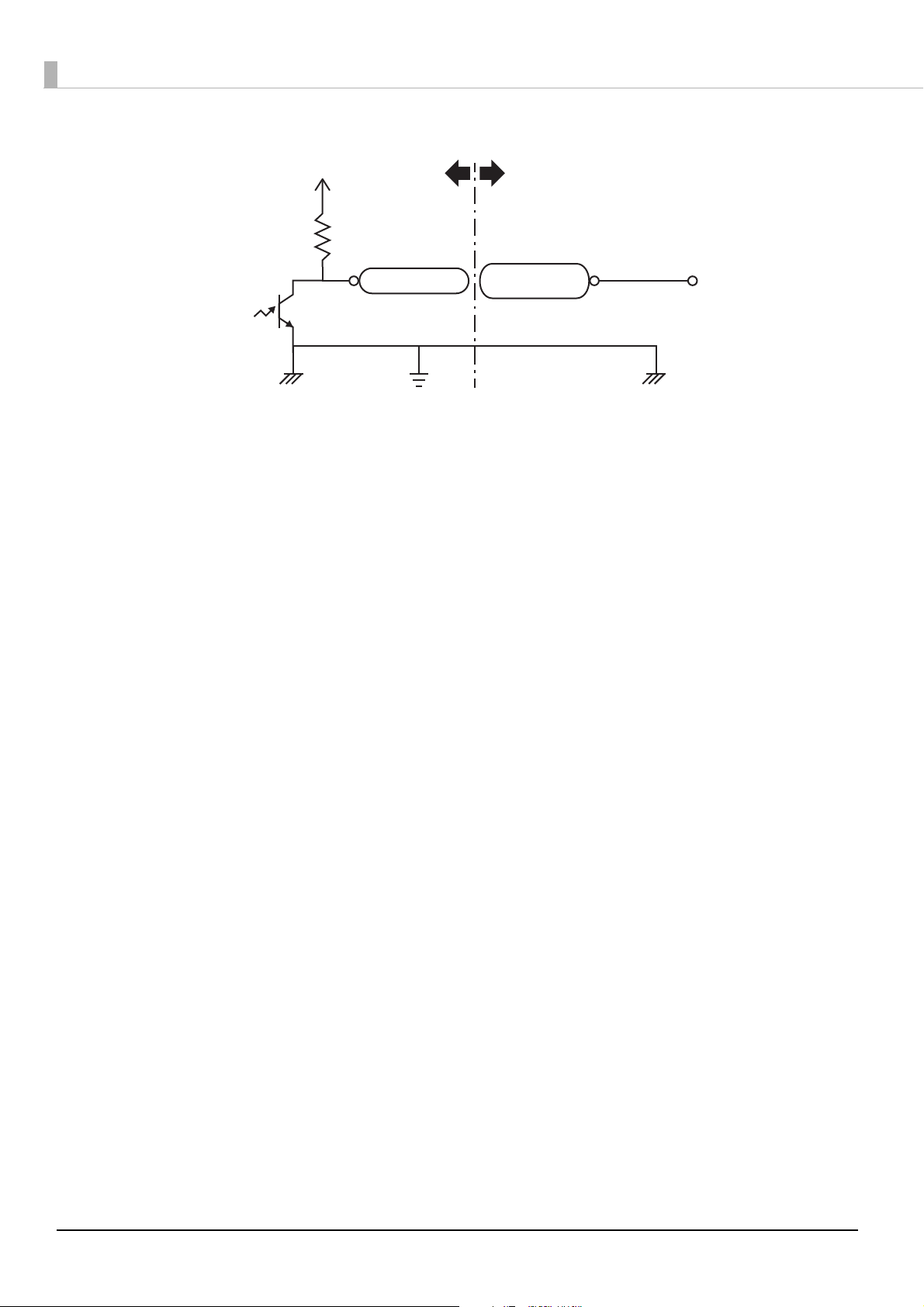
Example input signal circuit
Printer side External device side
External device
output
Printer input
VCC_EX
SG
Rpu
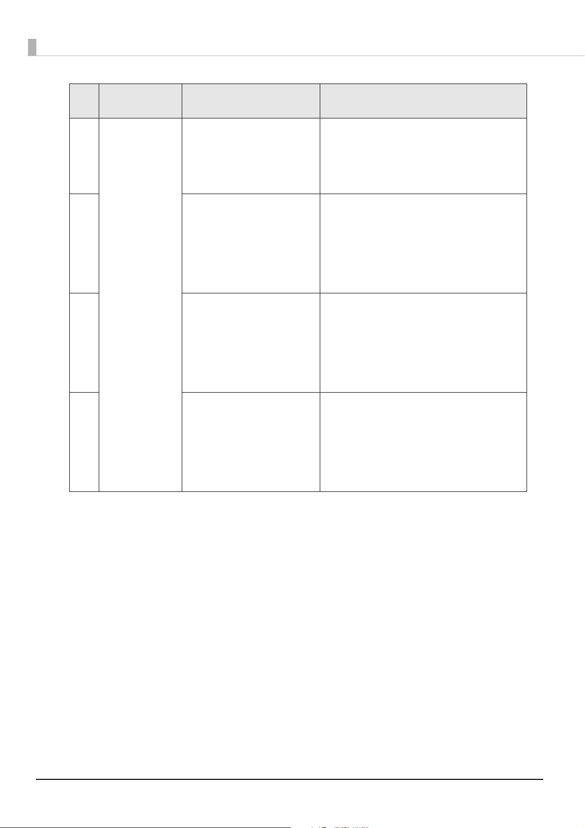
Printer side External device side
External device
input
Printer output
Example output signal circuit
VCC_EX
R
SG
58
Page 59

Switching the I/O Power Supply and SG
• To avoid the risk of electric shocks, if disassembling or assembling this product, first remove
WARNING
CAUTION
the power supply cord and all cables from this product.
• To prevent the possibility of electrical shock, do not perform maintenance, repair, or inspection during a thunderstorm.
• If you want to use a compressed air product, such as an air duster, for cleaning during repair
and maintenance, you must never use products containing flammable gas.
• Parts on the circuit board may become hot during operation. Therefore, wait approximately
10 minutes after turning the power off before touching them.
• Wear a grounded wrist band when handling the internal circuit board to prevent damage
from static electricity.
• Hold the exterior of the board.
• Be careful not to subject the circuit board to shock or vibration, because this may damage
it.
• Do not touch the circuit board or cable terminals with your hands to prevent contamination
that may result in a malfunction.
• Do not use an alcohol, benzine, thinner, trichloroethylene, or ketone‐based solvent to clean
the parts. This type of solvent may damage the plastic and rubber parts.
• As failures may be caused if liquid enters the interior of this product, do not place food or
drinks on top of the case.
• Wipe off any dirt with a dry or slightly moist cloth. Be sure to remove the power cord from
the outlet at this time.
Chapter 7 Appendix
The I/O signal power supply and SG are switched as follows.
Turn off the power supply of this product and remove the power supply plug from
1
the outlet.
Remove the screws (x 5) used to affix the left side cover.
2
59
Page 60

Remove the left side cover.
Left side cover
Encoder
3
Pull the top of the left side cover out towards you by 2 cm and then lift the whole cover up to remove
it.
While the left side cover is open, be absolutely sure not to touch the encoder inside this
CAUTION
product. Doing so could cause failures.
60
Page 61
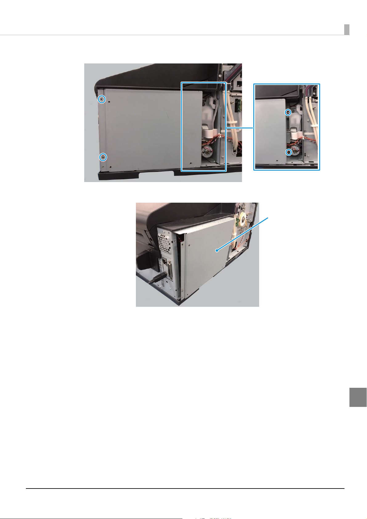
Remove the screws (x 4) used to affix the internal cover.
Internal cover
4
Remove the internal cover.
5
Chapter 7 Appendix
61
Page 62

Perform jumper settings. Pull out the connector jumper pin and insert it into the
CN100 CN200
Jumper pin
6
number to be set.
Press with your fingers on the right side of the interface board to affix it while pulling and inserting
the jumper pin.
• When shorting pins 1 and 2 on CN100, DO NOT short pins 2 and 3 on CN200.
c IMPORTANT
• When shorting pins 2 and 3 on CN100, DO NOT short pins 1 and 2 on CN200.
State CN100 JP setting CN200 JP setting
Power supply/SG not separated (Initial setting) 1-2 pin shorted 1-2 pin shorted
Power supply/SG separated 2-3 pin shorted 2-3 pin shorted
Once jumper settings are performed, install the covers using the following procedure.
Install the internal cover and affix it using the screws (x 4).
7
62
Install the left side cover and affix it using the screws (x 5).
8
 Loading...