

Epson CW-C6000Au, CW-C6000Pu, CW-C6000Ae, CW-C6000Pe, CW-C6010A Technical Reference Guide
...Page 1
Technical Reference Guide
Describes features for the product.
Describes setup and installation of the product.
Describes how to control the printer and necessary
information when you develop applications.
Describes specications of the product.
Describes how to handle the product.
Product Overview
Setup
Handling
Information for Application
Development
Appendix
M00125305
Rev.F
Page 2

Cautions
• All rights reserved. No part of this publication may be reproduced, stored in a retrieval system, or
transmitted in any form or by any means, electronic, mechanical, photocopying, recording, or otherwise,
without the prior written permission of Seiko Epson Corporation.
• The content of this manual is subject to change without notice. Please contact us for the latest information.
• While every precaution has been taken in the preparation of this manual, Seiko Epson Corporation assumes
no responsibility for errors or omissions.
• Neither is any liability assumed for damages resulting from the use of the information contained herein.
• Neither Seiko Epson Corporation nor its affiliates shall be liable to the purchaser of this product or third
parties for damages, losses, costs, or expenses incurred by purchaser or third parties as a result of: accident,
misuse, or abuse of this product or unauthorized modifications, repairs, or alterations to this product, or
(excluding the U.S.) failure to strictly comply with Seiko Epson Corporation's operating and maintenance
instructions.
• Seiko Epson Corporation shall not be liable for any damages or problems arising from the use of any options
or any consumable products other than those designated as Genuine Epson Products or Epson Approved
Products by Seiko Epson Corporation.
Trademarks
EPSON, EXCEED YOUR VISION, and ESC/Label are registered trademarks of Seiko Epson Corporation.
Microsoft®, Windows®, Windows Vista®, and Windows Server® are registered trademarks of Microsoft
Corporation in the United States and/or other countries.
Mac, mac OS, OS X, and ColorSync are trademarks of Apple Inc., registered in the U.S. and other countries.
Zebra Technologies Corporation and ZPL II are the registered trademarks or trademarks of Zebra Technologies
Corporation.
Intel®, Celeron®, and Pentium® are trademarks of Intel Corporation in the U.S. and/or other countries.
Adobe, the Adobe logo, Acrobat, Adobe PDF Print Engine, the Adobe PDF Print Engine logo, Illustrator,
Photoshop, PostScript and Reader are either registered trademarks or trademarks of Adobe in the United States
and/or other countries.
BarTender® is registered trademark of Seagull Scientific, Inc. in the United States and other countries.
NiceLabel® is trademarks or registered trademarks of Euro Plus d.o.o.
CODESOFT is registered trademarks or trademarks of TEKLYNX International.
All other trademarks are the property of their respective owners and used for identification purpose only.
©Seiko Epson Corporation 2019-2021.
2
Page 3
Before Use
This chapter describes information you should know before using the product.
Manuals for This Product
Paper manual
Manual viewable
with PC
Manual viewable
with PC
Start Here
Guides you through basic setup steps from unpacking to loading paper.
User’s Guide
Describes details about the functions and operating procedures of the product, maintenance
information, and troubleshooting. Download this guide from the web site or, depending on the
country or region, this is included in the supplied CD.
CW-C6000 Series/CW-C6500 Series Technical Reference Guide
(This manual)
Provides information necessary for installing the product, performing daily tasks, and
developing a system using the product.
Manual viewable
with PC
Online Video Manual
Provides videos that show you operating procedures and troubleshooting information. Access
the videos from the following URL.
<https://support.epson.net/p_doc/790/>
T
he contents of videos are subject to change without notice.
Downloading the Latest Version
The latest versions of the printer driver, utilities, and manuals can be downloaded from the following URLs.
For customers in North America, go to the following web site:
www.epson.com/support/
For customers in other countries, go to the following web site:
www.epson-biz.com/
3
Page 4
Symbols Used in This Guide
The following symbols are used in this guide to indicate important information.
Symbols for Safety
The symbols shown below are used in this manual in order to ensure safety and proper use of this product and
to prevent danger to you and other persons, and property damage. Be sure that you completely understand their
meanings before reading this manual.
Handling the product improperly by ignoring this symbol can lead to death or serious injury.
WARNING
Handling the product improperly by ignoring this symbol can lead to injury and property damage.
CAUTION
Symbols for General Information
c
IMPORTANT
Indicates information with which you must comply when using the product. Mishandling due to
ignoring this information may cause the product to fail or malfunction.
Indicates supplementary explanations and information you should know.
4
Page 5
Safety Precautions
To ensure safe use of the product, be sure to read this manual and the other instruction manuals supplied with
the product before use. Store this manual in a safe place so that you can resolve any unclear points regarding the
product at any time.
Cautions on Installation
Do not block the air vents of the product. ("Rear" on page 21)
Doing so can result in heat accumulated in the product causing a fire.
WARNING
CAUTION
Do not cover the product with a cloth or install it in a poorly-ventilated location.
Furthermore, ensure there is the installation space specified in the manual.
• Do not install/store the product in an unstable location or in a location subject to vibration from
other devices. The product may fall or collapse, causing breakage and possible injury.
• Do not install the product in a location exposed to oily smoke or dust, or in a humid location.
Doing so may cause electric shock or fire.
• When lifting the product, perform the work with the correct posture. Lifting the product with an
inappropriate posture may cause injury.
• Because the product is heavy, do not attempt to carry the product by one person. When
unpacking or moving the product, make sure to carry the product by at least two persons. See
below for details on the mass of this product. ("Product Specifications" on page 311)
• Do
not install the product at a location exposed to strong light such as direct sun rays. Doing so
may result in printing failure due to malfunction of the detectors.
• If the printer has charged matte black ink and is more likely to be exposed to a temperature of -10
or lower degrees C, make sure to discharge ink before turning the printer off. Otherwise, the print
head may be damaged due to freezing. ("Transporting or Storing the Printer at -10°C (With Matte
Bl
ack Ink Installed)" on page 265)
5
Page 6
Cautions on Handling
• Do not use the product in a location with volatile substances such as alcohol or paint thinner
present, or near fire. Doing so may cause electric shock or fire.
WARNING
• Shut down the product immediately if it produces smoke, a strange odor, or unusual noise. If you
go on using the product, it may result in electric shock or fire. If an abnormality occurs,
immediately turn off the power and remove the plug from the outlet, and then contact qualified
service personnel for advice.
• Shut down the product immediately if a foreign object or water or other liquid gets inside the
product. If you go on using the product, it may result in electric shock or fire. Immediately turn off
the power and remove the plug from the outlet, and then contact qualified service personnel for
advice.
• Do not disassemble the areas other than those mentioned in this manual.
• Never attempt to repair the product yourself as doing so is dangerous.
• Do not use the product in a location where inflammable gas, explosive gas, etc. is present in the
atmosphere. Furthermore, do not use aerosol sprayers containing flammable gas inside or around
the product. Doing so may cause fire.
• Do not connect cables in ways other than those mentioned in this manual. Doing so may cause
fire. It may also damage the other connected devices.
• Do not touch the areas inside the product other than those mentioned in this manual. Doing so
may cause electric shock or burns.
• Do not insert metal or flammable materials, or allow them to fall into the product. Doing so may
cause electric shock or fire.
• If the screen of the printer is damaged, handle the liquid crystal inside it very carefully. Should any
of the following situations arise, take emergency measures.
∗ When any part gets onto your skin, wipe off the deposit, and wash the area properly with soap
and water.
∗ When any part gets into your eyes, flush them with clean water for at least 15 minutes, and
thereafter, consult with a doctor.
∗ When a part gets into your mouth, immediately consult with a doctor.
CAUTION
• Do not allow anyone to stand or place heavy objects on top of the product. In particular, be
careful in the case of a household with children. The product may fall or collapse, causing
breakage and possible injury.
• Install the cables and optional products in the proper direction according to the proper
procedures. If they are installed improperly, it may result in fire or injury. Follow the instructions in
this manual to install them properly.
• Before moving the product, shut down and unplug the product, and make sure that all the cables
are disconnected. Failure to do so may damage a cable, causing electric shock or fire.
• Do not store or transport the product while it is tilted, standing, or upside down. Doing so may
cause the ink to leak.
• Do not use the printer with the paper cover removed. Doing so will cause the printer to
malfunction.
6
Page 7
Cautions on Power Supply
• Do not allow dust or other foreign material to adhere to the power plug. Doing so may cause
electric shock or fire.
WARNING
• Do not use a power cord other than that supplied with the product. In addition, do not use the
supplied power cord with another device. Doing so may cause electric shock or fire.
• Do not use a damaged power cord. Doing so may cause electric shock or fire. Contact qualified
service personnel for advice if the power cord is damaged. Furthermore, observe the following
points so as not to damage the power cord.
∗ Do not modify the power cord.
∗ Do not place heavy objects on the power cord.
∗ Do not forcibly bend, twist, or pull the power cord.
∗ Do not lay the power cord near a heating appliance.
• Do not insert or remove the power plug with a wet hand. Doing so may cause electric shock.
• Do not connect many power cords to one outlet. Doing so may cause fire. Supply power directly
from a power outlet.
• Regularly disconnect the power plug from the outlet and clean the base of the prongs and
between the prongs. Leaving the power plug connected to the outlet for a long period of time
may cause dust to accumulate on the base of the power plug prongs, resulting in a short and fire.
• Hold the plug and do not pull the cord when disconnecting the power plug from the outlet.
Pulling the cord may damage the cord or deform the plug, causing electric shock or fire.
To ensure safety, unplug the product before leaving it unused for an extended period.
CAUTION
7
Page 8
Cautions on Ink Cartridges
• The ink cartridges that can be used differ depending on the model number of the product. Use
ink cartridges suitable for the model number of your printer. ("Ink Cartridges" on page 358)
• Do
CAUTION
not touch the IC chip on an ink cartridge. Doing so may result in normal operation and
printing becoming no longer possible.
• The product uses ink cartridges equipped with IC chips to manage the amount of ink used and
other information so ink cartridges are usable even if they are removed and reinstalled. However,
if an ink cartridge with not much ink remaining is removed and reinstalled, it may not be usable.
Some ink is consumed each time cartridges are installed because the product automatically
checks their reliability.
• If the firmware version of the printer is other than TS05JC, TS06JC, TS26JC, TS19K2, TS25K3, or
TS21K5, you are prompted to select black ink type when turning on the printer and installing the
ink cartridges for the first time. Once the black ink cartridge is installed and the printer charge the
ink, you cannot change the black ink type any more. The printer does not work if you replace the
black ink cartridge with a cartridge of different type of black ink.
• Install all ink cartridges. Printing is not possible if even only one ink cartridge is missing.
• Since ink cartridges are designed to stop the operation before ink runs out completely to
maintain the quality of the print head, some ink remains in the used ink cartridges.
• All the ink colors are consumed also for the maintenance operations when an ink cartridge is
replaced and for print head cleaning.
• Do not turn off the power or open the ink cartridge cover during ink charging (while the
(power) LED lamp is flashing). Opening the cover may cause the ink to be recharged, resulting in
more ink being consumed. Also, it may result in normal printing becoming no longer possible.
• Even for monochrome printing, all the ink colors are used in an operation designed to maintain
the printing and print head quality.
• Do not disassemble an ink cartridge. Doing so may cause ink to get into eyes or onto skin.
• Do not disassemble or modify an ink cartridge. Doing so may cause printing malfunction.
• Use of old ink cartridges may result in reduced print quality. Use ink cartridges up within six
months after opening the packages. The usage period for ink cartridges is printed on the
packaging of the individual ink cartridges.
• If ink contacts your skin, eyes, or mouth, take the following actions.
∗ When ink gets onto your skin, immediately wash the area with soap and water.
∗ When ink gets into your eyes, immediately flush them with water. Leaving the ink as is may
result in bloodshot eyes or mild inflammation. If something is wrong, immediately consult with
a doctor.
∗ When ink gets into your mouth, immediately spit it out and consult with a doctor.
• There may be some ink around the ink supply port on a removed ink cartridge. Take care so that it
does not stain the desk or other surface.
• Do not open an ink cartridge package until you are ready to install the ink cartridge in the
product.
• Do not shake an ink cartridge too hard. The ink cartridge may leak if you shake it around too much
or push the sides strongly.
• Do not allow foreign objects to fall into the cartridge installation section.
Doing so may result in normal printing becoming no longer possible. Remove any object that falls
into the installation section, taking care not to damage the section.
• When ink is charged the first time (right after purchase), ink is consumed for filling the print head
nozzles (ink discharge holes) to get ready for printing. Therefore, the number of the sheets that
can be printed may be fewer than for cartridges installed later.
• When the printer is powered off with the (power) button, the print head is automatically
capped to prevent the ink from drying. When you will not use the printer after installing the ink
cartridges, be sure to turn the power off with the (power) button. Do not pull out the power
plug or turn off the breaker while the power is on.
8
Page 9
• Printing on water-repellent paper such as art paper, which is slow-drying, may cause print stains.
Also, if you print on glossy paper, fingerprints may get on the paper or ink may adhere to your
CAUTION
fingers when you touch the print surface. Select and use paper that will not cause print stains.
• Store the ink cartridges in a place out of reach of children.
• Epson recommends storing ink cartridges in a cool and dark place.
• If you wish to use ink cartridges that have been stored in a cold place for a long period of time,
leave them for at least 3 hours in a place that is at room temperature before use.
• Do not remove the ink cartridges from the product when storing or transporting the product.
Cautions on the Maintenance Box
• Store in a place out of reach of children. Do not drink any adhered ink.
• Do not disassemble or modify the maintenance box. Doing so may cause ink to get into eyes or
CAUTION
onto skin.
• Do not touch the IC chip on the maintenance box.
• If a maintenance box that can still be used has been removed and left detached for a long period
of time, do not reuse it.
• Do not peel off the film from the top surface of the maintenance box.
• If ink contacts your skin, eyes, or mouth, take the following actions.
∗ When ink gets onto your skin, immediately wash the area with soap and water.
∗ When ink gets into your eyes, immediately flush them with water. Leaving the ink as is may
result in bloodshot eyes or mild inflammation. If something is wrong, immediately consult with
a doctor.
∗ When ink gets into your mouth, immediately spit it out and consult with a doctor.
• Do not shake a used maintenance box too hard. The ink may leak from the maintenance box if
you swing or shake it too hard.
• Avoid storing the maintenance box under high temperatures or in a frozen state.
• Keep it away from direct sunlight.
9
Page 10
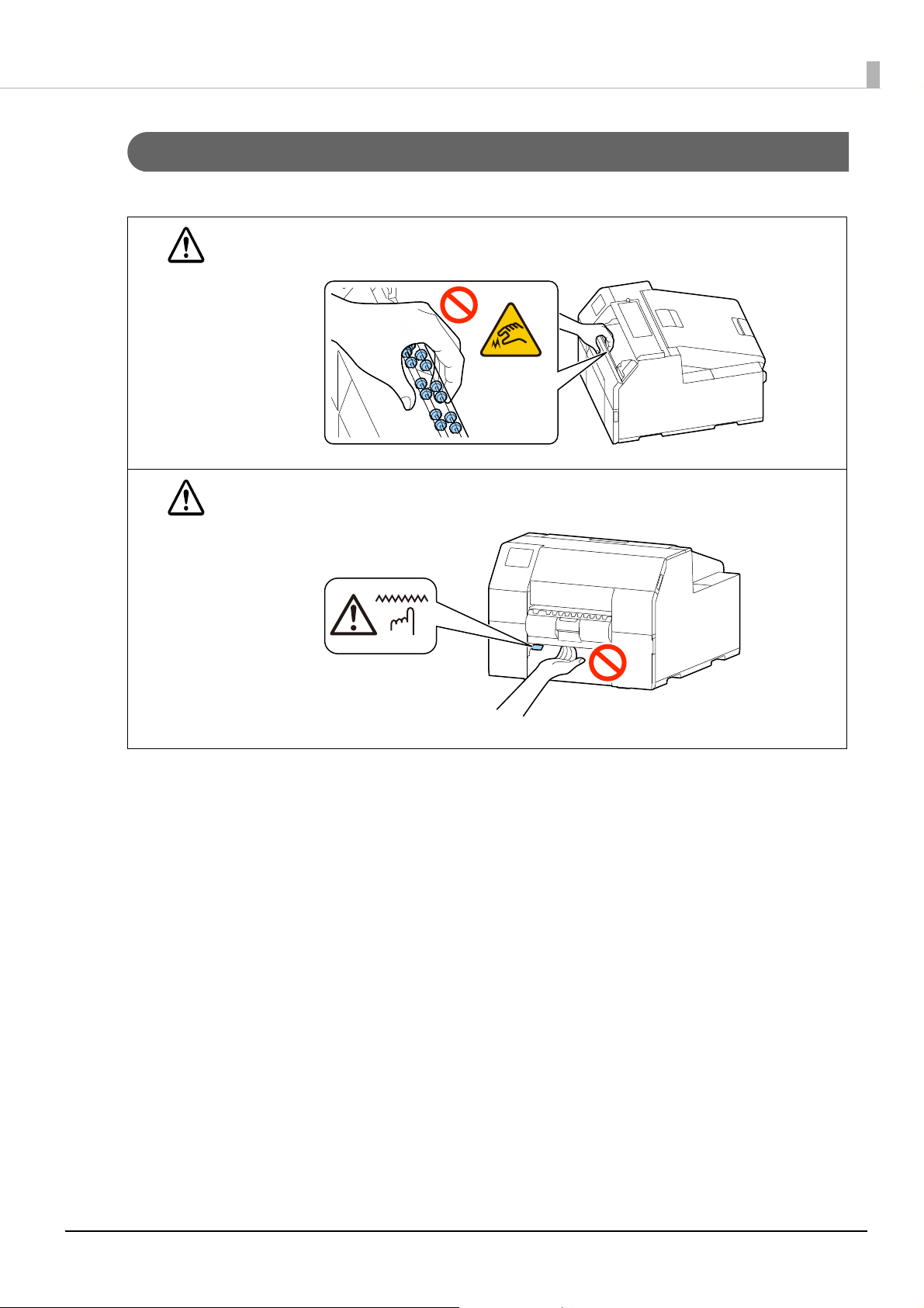
Caution Label
The labels affixed to the product indicate the following cautions.
Do not touch the roller at the bottom of the paper holder unit with your hand. Doing so may cause
injury.
WARNING
Do not touch the manual cutter at the bottom of the peeler cover with your hand. Doing so may
cause injury.
CAUTION
10
Page 11

Restriction of Use
When this product is used for applications requiring high reliability/safety such as transportation devices
related to aviation, rail, marine, automotive etc.; disaster prevention devices; various safety devices etc.; or
functional/precision devices etc., you should use this product only after giving consideration to including failsafes and redundancies into your design to maintain safety and total system reliability. This product is not
intended for use in applications requiring an extremely high level of reliability and safety, such as in aerospace
instruments, main communication equipment, nuclear power control equipment, or medical equipment, etc.
Please make your own judgment on this product's suitability after a full evaluation.
About This Manual
Aim of the Manual
This manual is intended to provide information required for developing, designing, and installing a system, and
for developing and designing printer applications for developers.
Manual Content
This manual consists of the following chapters.
Chapter 1 Product Overview
Chapter 2 Setup
Chapter 3 Handling
Chapter 4 Information for Application Development
Appendix Appendix
Screenshots
Unless otherwise noted, Windows 10 screenshots are used in this manual. Depending on the printer model and
OS version that you use, the screenshots may differ from actual Windows screens.
Depending on version of the printer driver and utility you are using, screens shown in this manual may slightly
differ from actual screens.
Illustrations
Unless otherwise noted, illustrations of CW-C6500 Series are used in this manual. They may look slightly
different from your printer.
11
Page 12

Contents
■ Before Use.................................................................................................................................3
Manuals for This Product................................................................................................................................................. 3
Symbols Used in This Guide........................................................................................................................................... 4
Safety Precautions ............................................................................................................................................................. 5
Cautions on Installation................................................................................................................................................... 5
Cautions on Handling ...................................................................................................................................................... 6
Cautions on Power Supply ............................................................................................................................................. 7
Cautions on Ink Cartridges ............................................................................................................................................. 8
Cautions on the Maintenance Box............................................................................................................................... 9
Caution Label .................................................................................................................................................................... 10
■ Restriction of Use ................................................................................................................. 11
■ About This Manual ...............................................................................................................11
Aim of the Manual ...........................................................................................................................................................11
Manual Content................................................................................................................................................................ 11
Screenshots........................................................................................................................................................................11
Illustrations.........................................................................................................................................................................11
■ Contents................................................................................................................................. 12
Product Overview ..........................................................................................18
■ About Models of this Product............................................................................................ 18
Auto cutter model ...........................................................................................................................................................18
Peeler model...................................................................................................................................................................... 18
Gloss Black Ink/Matte Black Ink ..................................................................................................................................19
About the Version of the Printer Driver and Utility.............................................................................................. 19
■ Part Names and Functions ................................................................................................. 20
Front .....................................................................................................................................................................................20
Rear ....................................................................................................................................................................................... 21
Inside .................................................................................................................................................................................... 22
Spindle and Flange..........................................................................................................................................................23
Operation Panel................................................................................................................................................................24
■ Nozzle Verification Technology ......................................................................................... 26
Nozzle Verification Technology Settings .................................................................................................................26
Dot Substitution (Supplemental Printing) Function........................................................................................... 28
■ Periodic Auto Cleaning ....................................................................................................... 29
Setting Time to Start the Periodic Auto Cleaning ................................................................................................29
Execution of the Periodic Auto Cleaning ................................................................................................................29
Examples of the Time Setting to Avoid Interrupting Printing Operation ....................................................29
■ Checking the Printer Status ............................................................................................... 30
Printing the Status Sheet .............................................................................................................................................. 30
Printing the Network Connection Check Report..................................................................................................31
Checking the Status of Consumables....................................................................................................................... 32
12
Page 13

Setup ...............................................................................................................33
■ Unpacking ............................................................................................................................. 33
■ Removing the Protective Materials .................................................................................. 34
■ Installing the Printer............................................................................................................ 35
■ Connecting the Power Cable ............................................................................................. 36
■ Turning On/Off ..................................................................................................................... 37
Turning the Power On ....................................................................................................................................................37
Turning the Power Off ....................................................................................................................................................37
■ Setting Language and Date/Time..................................................................................... 38
■ Selecting Black Ink Type ..................................................................................................... 38
■ Installing the Ink Cartridges .............................................................................................. 39
Replacing the Ink Cartridges........................................................................................................................................40
■ Installing the Maintenance Box......................................................................................... 42
Replacing the Maintenance Box.................................................................................................................................42
■ Installing the Printer Driver and Connecting to a Computer ...................................... 44
How to Get the Software...............................................................................................................................................44
How to Connect to a Computer..................................................................................................................................44
How to Configure the Network Settings .................................................................................................................44
Setup using Install Navi .................................................................................................................................................46
■ Media Settings...................................................................................................................... 47
■ Opening the Paper Cover ................................................................................................... 48
Opening the Cover using the Lever in the Front ..................................................................................................48
Opening the Cover using the Lever in the Back....................................................................................................48
■ Loading Paper....................................................................................................................... 49
How to Load Paper (Auto Cutter Model - Supply from Inside) ........................................................................50
How to Load Paper (Auto Cutter Model - Supply from Outside) ....................................................................54
How to Load Paper (Peeler Model - Supply from Inside)...................................................................................58
How to Remove Paper (For the Auto Cutter Model)............................................................................................63
How to Remove Paper (For the Peeler Model).......................................................................................................64
How to Eject Paper at Paper End (For the Auto Cutter Model) ........................................................................66
How to Eject Paper at Paper End (For the Peeler Model) ...................................................................................67
Feeding Paper into the Printer Manually.................................................................................................................68
■ Test Print ................................................................................................................................ 69
Test Print using the Printer Driver ..............................................................................................................................70
Handling .........................................................................................................71
■ Printer Driver for Windows................................................................................................. 71
Printer Driver Screen Configuration ..........................................................................................................................72
Paper Source and Paper Detection Settings ..........................................................................................................73
User-Defined Paper .........................................................................................................................................................75
13
Page 14

Printing Barcodes .............................................................................................................................................................84
Printing 2D Symbols........................................................................................................................................................95
Printing Barcodes / 2D Symbols on .NET Environment ................................................................................... 103
Favorite Settings............................................................................................................................................................ 105
User Defined Information ..........................................................................................................................................108
Exporting/Importing Printer Driver Settings ...................................................................................................... 108
Starting PrinterSetting from the Printer Driver .................................................................................................. 111
Speeding Up Printing using High Speed Batch Label Printing Function.................................................. 112
Sharing the Printer Driver ..........................................................................................................................................115
Setting EPSON Status Monitor 3.............................................................................................................................. 137
Restrictions on Using the Printer Driver................................................................................................................ 143
■ Printer Driver for Mac........................................................................................................ 144
Basic Procedure for Printing......................................................................................................................................144
Customizing the Printer Driver................................................................................................................................. 150
Epson Label Printer Utility.......................................................................................................................................... 152
■ Printer Driver for Linux ..................................................................................................... 154
Getting the Package (epson-inkjet-printer-cw-c6000c6500) ....................................................................... 155
Installing the Printer Driver ....................................................................................................................................... 155
Installing Input/Output Modules ............................................................................................................................ 155
Adding the Printer to the CUPS ............................................................................................................................... 155
Installing Epson Label Printer Utility for Linux ................................................................................................... 157
Starting Epson Label Printer Utility for Linux...................................................................................................... 157
Exiting Epson Label Printer Utility for Linux........................................................................................................ 158
Uninstalling Printer Driver, Epson Label Printer Utility for Linux ................................................................. 158
■ Printing from SAP System ................................................................................................ 160
Methods of Printing from SAP System .................................................................................................................. 160
Direct Printing ................................................................................................................................................................ 162
Indirect Printing............................................................................................................................................................. 162
High Volume Printing .................................................................................................................................................. 163
■ PrinterSetting (Windows)................................................................................................. 164
How to Start PrinterSetting ....................................................................................................................................... 165
How to Apply Settings ................................................................................................................................................ 166
Media settings ................................................................................................................................................................ 167
Layout settings............................................................................................................................................................... 168
Position adjustment .....................................................................................................................................................170
Print results adjustment..............................................................................................................................................172
Store data in the printer.............................................................................................................................................. 173
Background image settings ...................................................................................................................................... 177
Print head maintenance ............................................................................................................................................. 181
Printer settings............................................................................................................................................................... 182
Print Head Alignment..................................................................................................................................................183
Panel settings ................................................................................................................................................................. 188
Operating Time Settings.............................................................................................................................................189
Nozzle check settings .................................................................................................................................................. 190
Advanced settings ........................................................................................................................................................ 191
Initialize printer .............................................................................................................................................................. 199
Printer information ....................................................................................................................................................... 200
Settings save and restore ........................................................................................................................................... 202
Option ............................................................................................................................................................................... 203
14
Page 15

■ Operation Panel Settings.................................................................................................. 204
■ WebConfig........................................................................................................................... 218
■ Epson Device Admin.......................................................................................................... 220
■ Spot Color Settings............................................................................................................ 221
Creating Spot Color Setting File............................................................................................................................... 221
Printing using the Spot Color Setting File............................................................................................................ 226
■ Color Correction ................................................................................................................. 227
Vivid colors ...................................................................................................................................................................... 227
Setting using OS ............................................................................................................................................................ 228
Creating an ICC Profile.................................................................................................................................................235
No composite ................................................................................................................................................................. 239
■ Printing from the First Label (Auto cutter model only) .............................................. 240
■ Setting Label Size and Paper Layout for Borderless Printing.................................... 241
Borderless Printing Concepts.................................................................................................................................... 241
Label Media Design ......................................................................................................................................................241
Borderless Printing Settings ...................................................................................................................................... 242
■ Adjusting Sensitivity of the Detectors and Threshold for Detecting Labels .......... 245
■ Detecting Differences in Paper Size Using Label Command ..................................... 245
■ Adjusting Gap Detector .................................................................................................... 246
Adjusting Label Detector for Circle Die-cut Labels (Example)...................................................................... 247
■ Restricting Operation of the Operation Panel (Lock Setting function) ................... 248
Setting an Administrator Password ........................................................................................................................ 248
Enabling the [Lock Setting] Function .................................................................................................................... 249
Changing the Administrator Password ................................................................................................................. 249
Resetting the Administrator Password.................................................................................................................. 250
■ Cleaning the Printer........................................................................................................... 251
Cleaning the Exterior ...................................................................................................................................................252
Cleaning the Auto Cutter (Auto Cutter Model Only)........................................................................................ 253
Cleaning the Peeler (Peeler Model Only).............................................................................................................. 254
Cleaning the Edge Guides..........................................................................................................................................255
Cleaning the Platen ...................................................................................................................................................... 256
Cleaning the Paper Feed Roller................................................................................................................................ 257
Cleaning the Paper Pressure Roller......................................................................................................................... 260
Print Head Cleaning .....................................................................................................................................................262
Using the Operation Panel.........................................................................................................................................263
Using the Printer Driver .............................................................................................................................................. 263
Using the WebConfig...................................................................................................................................................263
■ Storing the Printer After Ink is Charged ........................................................................ 264
Preparation for Long-Term Storage ........................................................................................................................ 264
Transporting or Storing the Printer at -10°C (With Matte Black Ink Installed) ........................................ 265
For Using the Printer after Long Storage .............................................................................................................. 265
■ For Transporting the Printer ............................................................................................ 266
■ Troubleshooting................................................................................................................. 267
A message is displayed on the operation panel. ............................................................................................... 267
Print Quality Problems ................................................................................................................................................ 271
15
Page 16

Cannot Print .................................................................................................................................................................... 274
Network Connection Check Errors.......................................................................................................................... 276
A message is displayed on the computer screen ..............................................................................................277
Printing from a computer is impossible or becomes suddenly impossible............................................. 278
Print Job is Canceled on PC but “Printing” Message on Printer Does Not Disappear........................... 280
Error Beep Sound Does Not Stop ............................................................................................................................ 280
Paper is jammed ............................................................................................................................................................ 280
Information for Application Development.............................................. 287
■ How to Control the Printer ............................................................................................... 287
■ Using the Epson Inkjet Label Printer SDK ..................................................................... 288
Operating Environment.............................................................................................................................................. 288
How to Get Software.................................................................................................................................................... 288
■ Using the ESC/Label Commands..................................................................................... 288
■ Replacing from ZPL II Compatible Monochrome Printer ........................................... 289
Changing from Two-Step Printing to One-Step Printing................................................................................ 289
Utilizing Templates ....................................................................................................................................................... 309
■ Software and Manuals ...................................................................................................... 310
Appendix...................................................................................................... 311
■ Product Specifications ...................................................................................................... 311
Operating Environment.............................................................................................................................................. 312
Paper Specifications ..................................................................................................................................................... 313
Electrical Specifications .............................................................................................................................................. 348
Reliability.......................................................................................................................................................................... 348
Environmental Specifications ................................................................................................................................... 349
Overall Dimensions ...................................................................................................................................................... 350
■ Consumables Specifications ............................................................................................ 358
Ink Cartridges ................................................................................................................................................................. 358
Maintenance Box........................................................................................................................................................... 359
■ Option Specifications........................................................................................................ 360
Roll Paper Holder...........................................................................................................................................................360
■ Requirements for External Devices ................................................................................ 361
Media Source Setting ..................................................................................................................................................361
Paper Feed Speed ......................................................................................................................................................... 361
Paper Tension.................................................................................................................................................................. 362
Paper Curl......................................................................................................................................................................... 363
Paper Angle for Feeding and Ejecting ................................................................................................................... 364
Position of Paper Feeder and Paper Rewinder ................................................................................................... 365
■ Downloading Printer Driver, Utilities, and Manuals.................................................... 366
■ Label Print Applications.................................................................................................... 366
How to Get Software.................................................................................................................................................... 366
16
Page 17

■ For Inquiries ........................................................................................................................ 367
17
Page 18
Chapter1 Product Overview
CW-C6000 Series (4-inch model)
ColorWorks C6000Au, ColorWorks C6000Ae, ColorWorks C6010A,
ColorWorks C6020A, ColorWorks C6030A, ColorWorks C6040A,
ColorWorks C6050A
CW-C6500 Series (8-inch model)
ColorWorks C6500Au, ColorWorks C6500Ae, ColorWorks C6510A,
ColorWorks C6520A, ColorWorks C6530A, ColorWorks C6540A,
ColorWorks C6550A
CW-C6000 Series (4-inch model)
ColorWorks C6000Pu, ColorWorks C6000Pe, ColorWorks C6010P,
ColorWorks C6020P, ColorWorks C6030P, ColorWorks C6040P,
ColorWorks C6050P
CW-C6500 Series (8-inch model)
ColorWorks C6500Pu, ColorWorks C6500Pe, ColorWorks C6510P,
ColorWorks C6520P, ColorWorks C6530P, ColorWorks C6540P,
ColorWorks C6550P
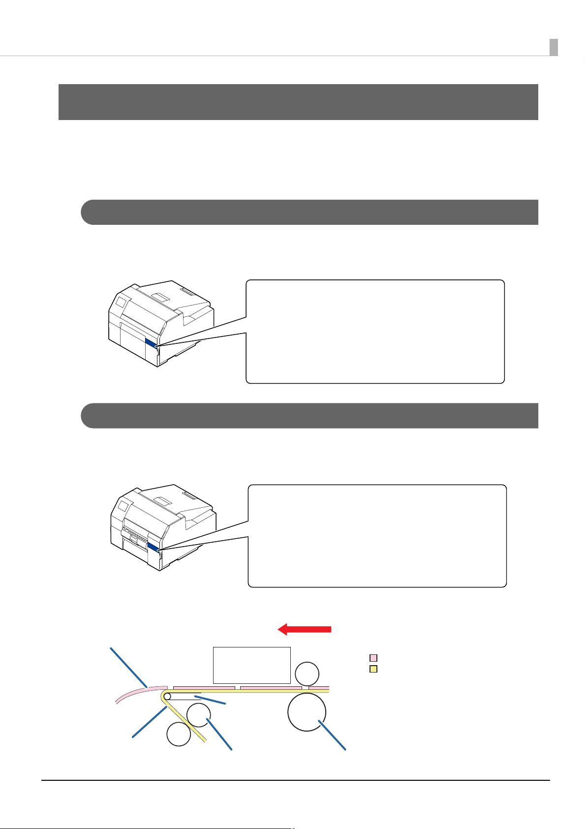
Paper feed direction
Label
Backing paper
Label
Peeling plate
Backing paper
Backing paper reed roller
Paper feed roller
Print head
Product Overview
This chapter describes features of the product.
About Models of this Product
Auto cutter model
Features: Equipped with an auto cutter. The paper can be cut either according to the application settings, or
with the help of the Cut button on the operation panel.
Model number:
Peeler model
Features: Equipped with a peeler mechanism. By passing a backing paper through the peeler, labels are printed
being peeled from the backing paper.
Model number:
Lateral view (when waiting the printed label to be removed):
18
Page 19
Chapter1 Product Overview
Gloss Black Ink/Matte Black Ink
If the firmware version of the printer is other than TS05JC, TS06JC, TS26JC, TS19K2, TS25K3, or TS21K5, you
can select which type of black ink to use from gloss black and matte black. The printer prompts you to select it
when you turn on the printer for the first time.
You cannot change the black ink type once you select the black ink type and let the printer charge
c
the ink.
IMPORTANT
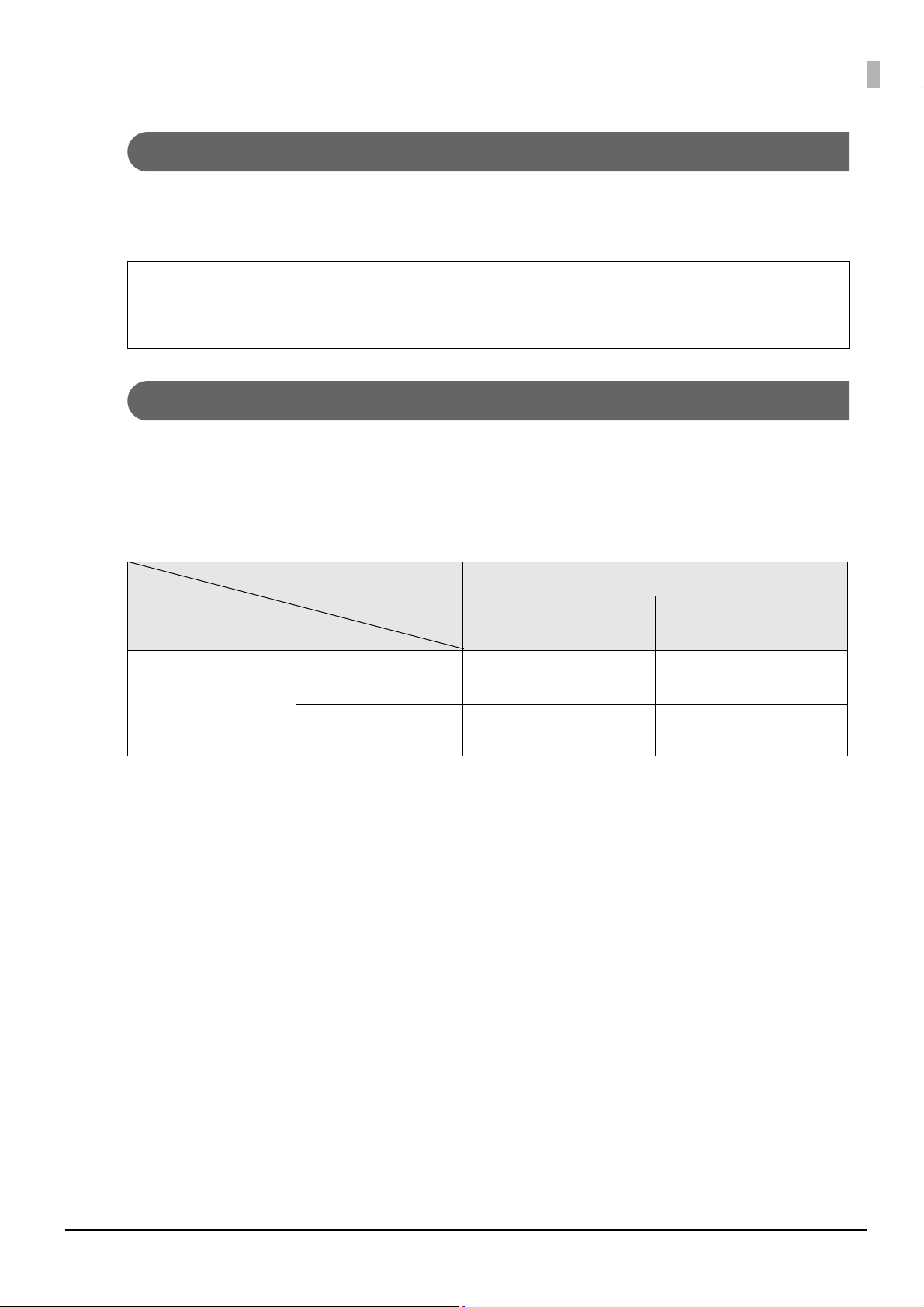
About the Version of the Printer Driver and Utility
Depending on the firmware version of the printer, available versions of the printer driver and utility vary.
Use the combination indicated as "Available (Recommended)" in the table below. In addition, download and use
the latest version of firmware.
You can use the combinations indicated as "Available", however, the printer may malfunction or there may be
restrictions on some functions.
Driver/PrinterSetting Version
Ver.1.0.0.0 / Ver.1.1.0.0
Printer firmware version TS05JC, TS06JC, TS26JC,
TS19K2, TS25K3, TS21K5
Versions higher than
those in the above row.
You can check the version of your printer firmware by using one of the following methods.
• Printing the status sheet ("Printing the Status Sheet" on page 30)
• Checking on the operation panel ("Operation Panel Settings" on page 204)
o get the latest version of the printer driver and utility, see "Downloading Printer Driver, Utilities, and
T
anuals" on page 366.
M
Available Not available
Not available Available (Recommended)
Versions higher than
those in the left column
19
Page 20
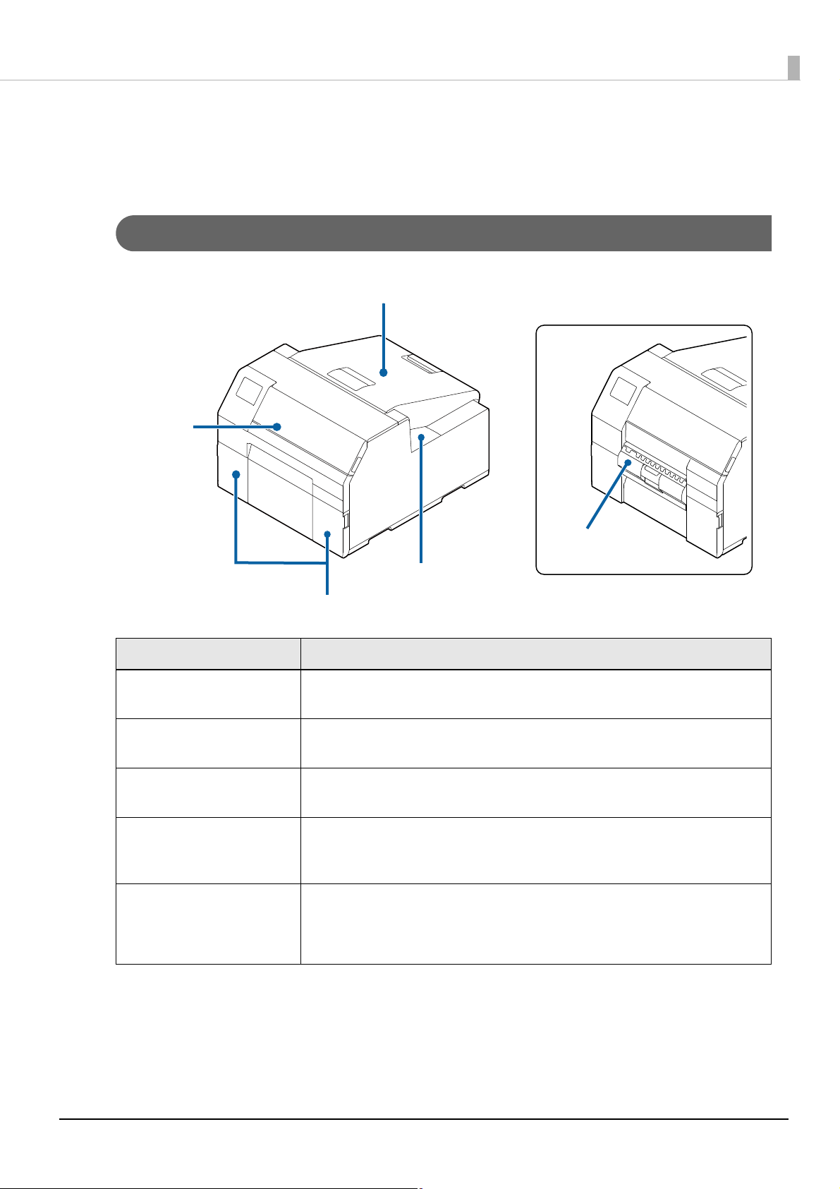
Part Names and Functions
Paper cover
Front cover
Ink cartridge cover
Maintenance box cover
Peeler cover
Peeler model
This section describes the main operation parts.
Front
Chapter1 Product Overview
Name Description
Front cover Open this cover to remove paper if it is jammed.
("Paper is jammed" on page 280)
I
nk cartridge cover Open this cover to install/replace the ink cartridge.
("Replacing the Ink Cartridges" on page 40)
Maintenanc
P
aper cover Open this cover to load or replace paper. How to open the paper cover differs
P
eeler cover
(peeler model only)
e box cover Open this cover to install/replace the maintenance box.
("Replacing the Maintenance Box" on page 42)
depending on whether the paper is to be supplied from the inside or the outside.
("Opening the Paper Cover" on page 48)
Open this cover to load paper. By passing a backing paper through the peeler, labels
are printed being peeled from the backing paper. The cover is equipped with a label
peeling detector, which detects whether a peeled label is remaining at the paper
ejection slot or not.
20
Page 21
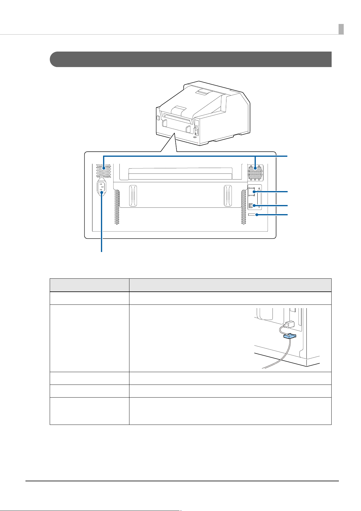
Rear
Air vent
LAN port
USB port
Wire saddle
Power connector
Chapter1 Product Overview
Name Description
Power connector Connect the power cable.
Wire saddle Pass the USB cable through this saddle to
prevent disconnection of the cable.
USB port Connect a USB cable.
LAN port Connect a LAN cable.
Air vent Exhausts heat generated in the printer to prevent the temperature inside the printer
from rising. Provide a clearance of 10 cm {3.94"} or more from the area around the air
vent to ensure ventilation when installing the printer.
21
Page 22
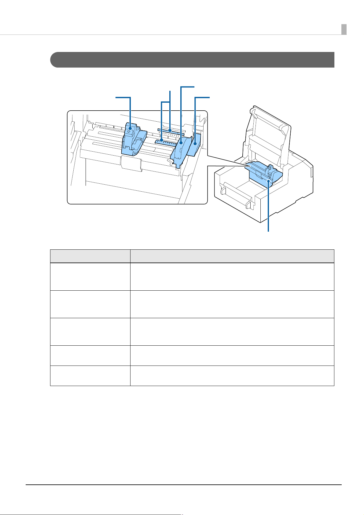
Inside
Movable edge guide
Gap detector
Edge guide
Release lever
Paper guide unit
Chapter1 Product Overview
Movable edge guide Supports paper at the paper width position while the paper is fed into the printer.
Gap detector You can adjust the position of the gap detector. The adjustment is necessary before
Rele
ase lever Use this lever when removing a jammed paper. By moving the lever up, the paper
Edge guide Supports paper while the paper is fed into the printer. When loading paper, load the
Paper guide unit Move this unit when cleaning the paper feed roller. If you pull the blue lever, the entire
Name Description
Squeeze the blue lever to move the edge guide. Adjust them to match the paper
width.
printing on odd-shaped labels such as circle or oval. ("Adjusting Gap Detector" on page
246)
pressure rollers are unlocked and you can remove paper jammed inside the front
cover.
paper along this guide.
unit moves, and you can check the paper feed roller.
22
Page 23
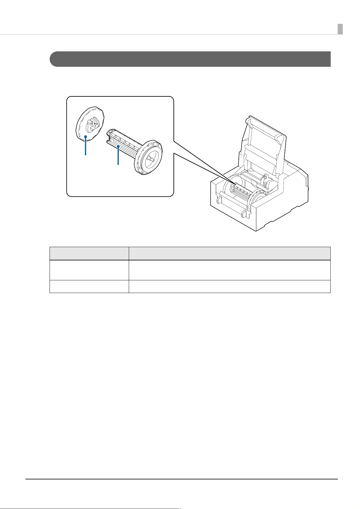
Spindle and Flange
Flange
Spindle
Used to supply the paper from the inside.
Chapter1 Product Overview
Name Description
Flange Attach this to the spindle to fix the roll paper loaded on the spindle. Squeeze the blue
lever to attach or remove to/from the spindle.
Spindle Load roll paper on this spindle.
23
Page 24
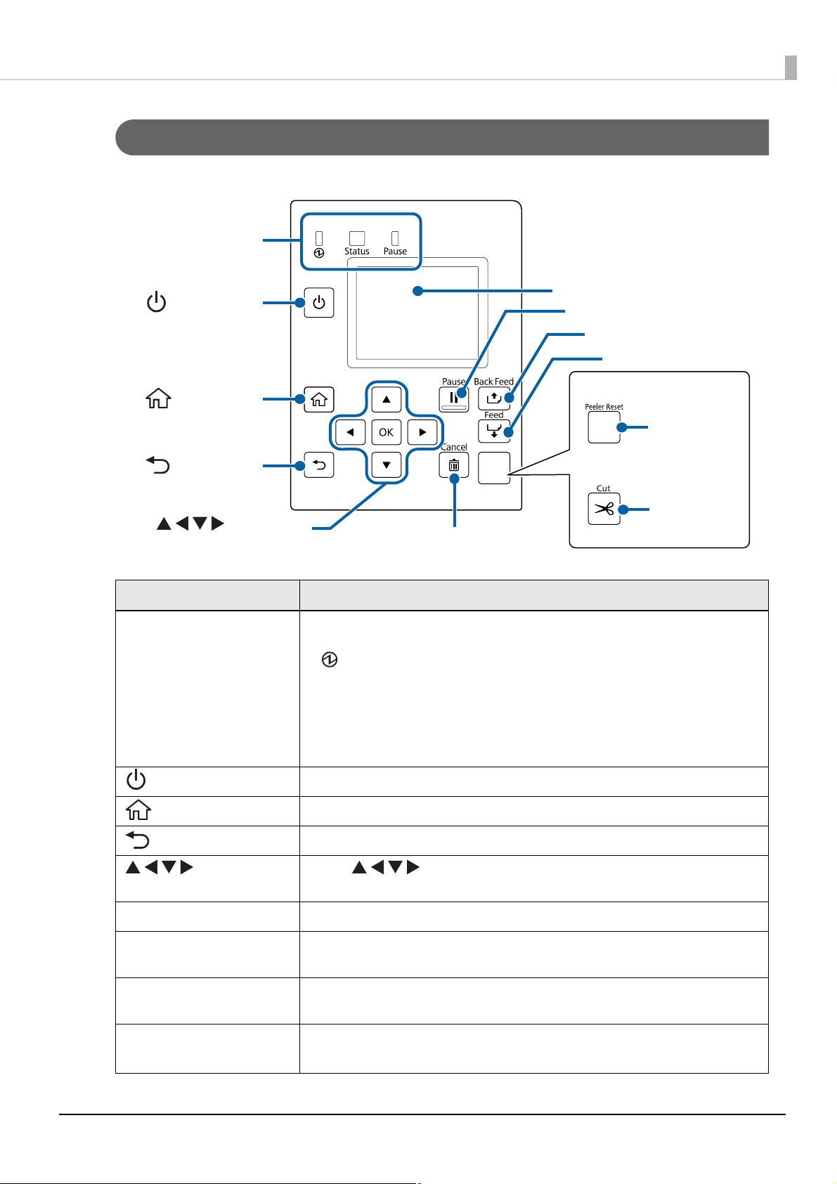
Operation Panel
LED
Peeler model
Auto cutter model
Screen
Cancel button
Pause button
Back Feed button
Feed button
Peeler Reset
button
Cut button
(power) button
(select) button,
OK button
(home) button
(back) button
Chapter1 Product Overview
Name Description
LED The status of the printer can be checked from the flashing of the LEDs. This allows you
to know the cause of an error and how to resolve the problem.
• (power) LED
Stays on while the printer is on. Flashes during printing or charging ink.
• Status LED
Stays on or flashes while an error or problem is occurring.
• Pause LED
Stays on or flashes while the printer is paused.
(power) button Turns on/off the printer.
(home) button Displays the Home screen.
(back) button Use to return to the previous screen.
(select) button,
OK button
Cancel button Press this to cancel a print job.
Cut button
(Auto cutter model only)
Peeler Reset button
(Peeler model only)
F
eed button Press this briefly to feed paper by one page.
Use the keys to select a menu item, and then press the OK button to
activate the selected menu or setting.
Use to cut paper. The paper cannot be cut twice at the same position.
Press this button if printing of the next data does not start even after removing printed
labels. For details, refer to "Cannot Print" on page 274.
Hold down to feed paper continuously.
24
Page 25
Chapter1 Product Overview
Message
Paper information
Ink levels/
Waste ink level
Settings
menu
Help
menu
Name Description
Back Feed button Use to replace paper. Hold down this button to feed the paper backward until you can
pull the paper out of the printer.
Pause button While printing: Press to stop printing after printing the current page. Press again to
resume printing.
During standby: Press to stop the printer temporarily. Press again to put the printer
back into the standby state.
Screen Status of the printer, menus, and error messages are displayed.
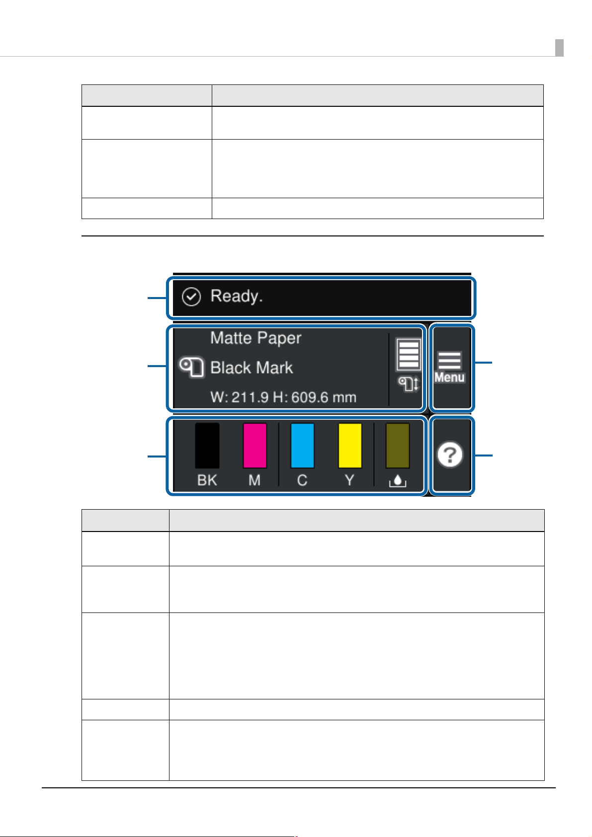
Home Screen
Name Description
Message A printer status or an error message is displayed.
("A message is displayed on the operation panel." on page 267)
P
aper information The current paper settings are displayed. For a roll paper, approximate remaining paper length of
the roll is also displayed.
Touch this area to directly access the [Paper Settings] menus.
Ink levels/
Waste ink level
Help menu button You can see troubleshooting information and basic operating procedures.
Settings button Allows you to access the maintenance menus, various printer settings, and network settings.
The length of the bars indicate how much ink of each color is remaining, and how much space in
the maintenance box is remaining. The shorter the bars are, the lower the ink levels and remaining
space are.
A [ ! ] mark will appear when the ink cartridge or the maintenance box needs to be replaced soon.
A [ x ] mark will appear when the ink cartridge or the maintenance box needs to be replaced.
Matte black ink is displayed as "MK".
Throughout this manual, touching this button is indicated as [Menu].
All the settings available from this button are listed in the link below.
("Operation Panel Settings" on page 204)
25
Page 26
Chapter1 Product Overview
Nozzle Verification Technology
The “Nozzle Verification Technology” allows the printer to detect clogging of the print nozzles by self-check.
Depending on required print quality, you can enable or disable the “Nozzle Verification Technology” function,
set how often to run the self-check, threshold for the check, and whether to run a cleaning after the check. In
addition to that, if nozzle clogging is not cleared by the cleaning, the printer carries out supplemental printing
using nozzles adjacent to the clogged nozzles.
By using this function, you can prevent sharp decline in the print quality and barcode quality.
Nozzle Verification Technology Settings
Self nozzle check is run at the following times.
• When the printer is turned on.
• When the front cover or the paper cover is closed after a paper jam.
• Just before running a regularly scheduled cleaning.
("Periodic Auto Cleaning" on page 29)
f the “Nozzle Verification Technology” function is enabled, self nozzle check is run at the following time.
I
• When the number of printouts has reached the number specified as the interval of the self-check.
If the result of self nozzle check exceeds the specified threshold, a head cleaning is run automatically to clear the
nozzle clogging. After the cleaning, the self nozzle check is run again. If the result of the check still exceeds the
threshold, auto cleaning is also run again.
This function cannot provide 100% accuracy guarantee for preventing drop in print quality due to
nozzle clogging. The printer cannot perfectly detect missing dots and skewed ink drops on printouts.
CAUTION
• The cleaning cleans the entire print head. It does not clean the print head partially for cleaning
only the clogged nozzles.
• A small amount of ink is consumed for this Nozzle Verification Technology function.
• The print head cleaning is run automatically after the self nozzle check when set to do so. Ink is
consumed for the head cleaning.
Enabling/Disabling the Nozzle Verification Technology
You can enable or disable the Nozzle Verification Technology function.
The factory default is “Enable”.
How to Set
Set using the operation panel of the printer, or using PrinterSetting.
See "Operation Panel Settings" on page 204 or "PrinterSetting (Windows)" on page 164.
26
Page 27
Chapter1 Product Overview
Setting Auto Nozzle Check Interval
Specify the number of printouts to let the printer run the nozzle check when reached the number. The printer
will stop while running the check.
How to Set
Set using the operation panel of the printer, or using PrinterSetting.
Specify the number in the range of 1 to 13000.
See "Operation Panel Settings" on page 204 or "PrinterSetting (Windows)" on page 164.
• The count of printouts is reset when the specified number is reached and nozzle check is performed,
and when the printer is turned off.
• The factory default is “500”.
Setting Threshold of Nozzle Clogging
Specify the threshold of nozzle clogging. If the number of detected clogged nozzles exceed the threshold, a
message is displayed on the printer’s screen. You can set to run an auto head cleaning in such a case. If the
number of clogged nozzles is below the threshold, you can use the supplemental printing function.
How to Set
Set using the operation panel of the printer, or using PrinterSetting.
Specify the number in the range of 0 to 16 nozzles.
See "Operation Panel Settings" on page 204 or "PrinterSetting (Windows)" on page 164.
• The number of nozzles is the total of four color (BK (MK), C, M, Y) nozzles.
• The factory default is “6”.
Setting Auto Cleaning after Nozzle Check
You can set to run an auto head cleaning when the number of detected clogged nozzles exceeds the threshold.
When this setting is enabled: A message is displayed on the printer’s screen and the cleaning is run
automatically when the number of detected clogged nozzles exceeds the threshold.
When this setting is disabled: A message is displayed on the printer’s screen when the number of detected
clogged nozzles exceeds the threshold, but the cleaning is not run.
How to Set
Set using the operation panel of the printer, or using PrinterSetting.
The factory default is “Enable”.
See "Operation Panel Settings" on page 204 or "PrinterSetting (Windows)" on page 164.
27
Page 28

Chapter1 Product Overview
Dot Substitution (Supplemental Printing) Function
The “Dot Substitution” function automatically supplements missing dots caused by clogged nozzles with dots
generated by nozzles adjacent to the clogged nozzles. The number of nozzles that can be supplemented is up to
16 nozzles. However, if the clogged nozzles are located next to each other, the supplementation does not work
well. If the number of clogged nozzles exceeds 16, supplementation for 16 nozzles is performed without
stopping the printing operation.
You cannot use this function if you have disabled the Nozzle Verification Technology function. Enable the
Nozzle Verification Technology function to use this function.
• This function cannot perfectly supplement missing dots, so drop in print quality or barcode quality
can occur even if this function is used.
• Since the supplementation is performed according to information of clogged nozzles that has been
acquired when starting printing, nozzles that get clogged during printing are not supplemented.
How to Set
Set using the operation panel of the printer, or using PrinterSetting.
The factory default is “Enable”.
See "Operation Panel Settings" on page 204 or "PrinterSetting (Windows)" on page 164.
28
Page 29
Chapter1 Product Overview
Periodic Auto Cleaning
Sometimes, the printer runs a periodic cleaning automatically to maintain the print head in good condition.
The cleaning takes 3 to 14 minutes, and printing is disabled during the cleaning. To prevent the cleaning from
running when you want to print, set the time to start the periodic auto cleaning.
The cleaning will start at the specified time. However, the cleaning is not run if the printer determines that the
print head does not need to be cleaned.
Setting the cleaning start time allows you to clean the print head without interrupting printing operation. The
default time is “0:00”.
Setting Time to Start the Periodic Auto Cleaning
Set using the operation panel of the printer, or using PrinterSetting.
During the cleaning, printing is disabled. Specify a time when the printer is on but not in use. The time can be
set in one-minute increments.
For the setting procedure, see "Operation Panel Settings" on page 204 or "Printer settings" on page 182.
• The cleaning takes 3 to 14 minutes.
• If you set a time within less than 10 minutes from the current time, the cleaning is run at the set time
24 hours later.
Execution of the Periodic Auto Cleaning
At the set time, the cleaning is automatically run if the printer is on and it determines that the cleaning is
necessary.
• If the printer has been left unused without being powered on for a long time, the cleaning may be run
when the printer is turned on.
• In the following cases, the cleaning is not run at the set time. It is run next time the printer is turned
on.
- The printer is not powered on.
- The ink level is too low to run the cleaning, or some ink cartridge(s) needs to be replaced.
- The remaining amount of space in the maintenance box is too low to run the cleaning, or the box
needs to be replaced.
Examples of the Time Setting to Avoid Interrupting Printing Operation
The followings are examples of the cleaning start time setting to reduce the likelihood of unintended cleaning
during printing.
In the case that the printer is always powered on
Set the time to a time that printing work is not performed, such as midnight.
In the case that the printer is powered on and off every day
• Set the time to a time that the printer is off, such as midnight, to let the printer run the cleaning right after it
is powered on.
• If printing work is not performed during lunch break, set the time to a time such as 12:00 in order to let the
printer run the cleaning during the lunch break.
29
Page 30
Chapter1 Product Overview
Checking the Printer Status
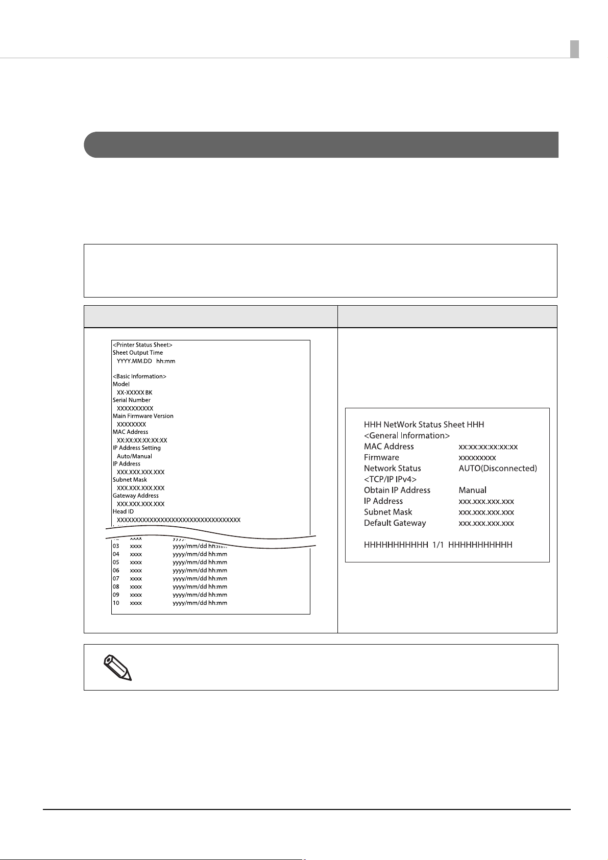
Printing the Status Sheet
By printing the status sheet, you can check the firmware version and the current printer settings, such as print
mode and media detection settings.
On the operation panel, select the menu in the order shown below to print the status sheet.
[Menu] - [Printer Status/Print] - [Print Status Sheet]
To print the status sheet, load paper that has a label that measures at least 4 inches width and 6
c
IMPORTANT
inches long.
Status Sheet Example Status Sheet (Network Settings) Example
You can also print a list of registered fonts, barcode fonts, images or templates.
30
Page 31

Chapter1 Product Overview
Printing the Network Connection Check Report
By printing the network connection check report, you can check the network connection status and the network
settings.
On the operation panel, select the menu in the order shown below to print the report.
[Menu] - [General Settings] - [Network Settings] - [Connection Check]
To print the network connection check report, load paper that has a label that measures at least 4
c
IMPORTANT
inches width and 6 inches long.
Network Connection Check Report Example
31
Page 32

Chapter1 Product Overview
Checking the Status of Consumables
On the home screen of the printer, you can check the following information; the status of the ink cartridges and
the maintenance box, paper settings (paper type, detection method, label width/length), remaining amount of
paper. ("Home Screen" on page 25)
32
Page 33

Setup
This chapter describes procedures for installing and setting up the printer that are required before using the
printer.
Unpacking
After unpacking, make sure that all the printer and the accessories are included and they have no damages.
The included items are as follows.
Chapter2 Setup
1 Printer (CW-C6000 Series or CW-C6500 Series) 2 Ink cartridges for initial setup; C, M, Y, BK (MK)*
* Either one of a BK (gloss black) cartridge or MK
(matte black) cartridge is included.
3 Roll paper (for initial operation check) 4 Flange and Spindle
5 Power cable 6 USB cable
7 CD-ROM (not included depending on country or
region)
9 Power cable for specific regions (not included
depending on country or region)
8Manual
33
Page 34

Removing the Protective Materials
Remove the all protective materials such as pieces of tape and cushion materials. There are about eight
protective materials and some of them have been attached to inside the printer.
Chapter2 Setup
34
Page 35

Chapter2 Setup
Installing the Printer
Allow sufficient space for the printer. Make sure that the installation location meets the following requirements.
• On a level and stable surface with sufficient strength to support the weight of the printer
Auto cutter model Peeler model
CW-C6000 Series Approx. 22.5 kg Approx. 22.8 kg
CW-C6500 Series Approx. 25.5 kg Approx. 26.3 kg
• On an area larger than the bottom surface of the printer.
• A location that is not subject to vibrations and impacts.
• A location where a dedicated power outlet is available.
• A location where you can load and remove paper without difficulty.
• A location with sufficient space around the printer to allow for installation of accessories, replacement of
consumable products, and daily cleaning.
• A location that meets the following environmental requirements.
For more details, see "Environmental Specifications" on page 349.
Te mp e ra tu r e Humidity
Printing 5 to 35°C 20 to 80% RH, No condensation
Storage Gloss black ink -20 to 40°C 5 to 85% RH, No condensation (without being unpacked)
Matte black ink -10 to 40°C
• Make sure to carry the printer by two or more persons.
• To lift the printer, put your hands on the indented portions on the side of the printer as shown
CAUTION
below. If you put your hands on the other portions of the printer to lift it, the printer may get
damaged.
• Do not install the product at a location exposed to strong light such as direct sun rays. Doing so
may result in printing failure due to malfunction of the detectors.
• If the printer has charged matte black ink and is more likely to be exposed to a temperature of -10
or lower degrees C, make sure to discharge ink before turning the printer off. Otherwise, the print
head may be damaged due to freezing. For more details, see
on page 264
.
"Storing the Printer After Ink is Charged"
35
Page 36

Connecting the Power Cable
Follow the procedure below to connect the power cable.
Install the printer near a wall outlet so that you can disconnect the plug from the outlet immediately
in the event of an emergency.
WARNING
Insert the power cable firmly all the way into the power connector on the back of the
1
printer.
Insert the power plug firmly all the way into an outlet.
2
Chapter2 Setup
36
Page 37

Turning On/Off
ON
Turning the Power On
Hold down the (power) button until the (power) LED lights up.
Chapter2 Setup
Turning the Power Off
Press the (power) button. Then select [Yes] on the confirmation screen. The (power) LED goes out and
the printer is turned off.
37
Page 38

Setting Language and Date/Time
Follow the on-screen instructions to set language, the date and time.
Chapter2 Setup
Selecting Black Ink Type
If the version of the printer firmware is other than TS05JC, TS06JC, TS26JC, TS19K2, TS25K3, or TS21K5,
select which type of black ink you use following the on-screen instructions.
On the black ink type confirmation screen, select [Done].
38
Page 39

Chapter2 Setup
Installing the Ink Cartridges
Follow the on-screen instructions to install the ink cartridges.
When you close the cover, a message that confirms whether to start initial ink charging is displayed. Select [Yes]
to start the initial ink charging. When you see a message saying that the initial ink charging is finished, select
[OK].
If the version of the printer firmware is TS05JC, TS06JC, TS26JC, TS19K2, TS25K3, or TS21K5, initial ink
charging will start right after you install the cartridges and close the cover. A home screen is displayed when the
initial ink charging is finished.
It takes about 19 minutes for the initial ink charging. The time differs according to circumstances.
Before installing the ink cartridges, make sure to read the cautions on handling the ink cartridges.
See "Cautions on Ink Cartridges" on page 8.
Nev
CAUTION
er open any cover of the printer or turn off the printer during ink charging.
Doing so will consume a large amount of ink, which may result in the need to replace the ink
cartridges or the maintenance box before the completion of charging.
Once you start the initial ink charging, you cannot change the black ink type.
19 min.
39
Page 40

Chapter2 Setup
Replacing the Ink Cartridges
Checking Amount of Ink Remaining
You can check ink level of each color ink cartridge on the home or an error message screen of the operation
panel.
Message Description
You need to replace Ink Cartridge(s). To maintain the quality of the print head, the printer stops printing before ink car-
tridges are completely expended. Replace the ink cartridge with new one.
How to Replace the Ink Cartridges
When replacing the black ink cartridge, make sure to replace with a cartridge of the same type of
c
IMPORTANT
black ink. The printer does not work if you install a cartridge of different type of black ink.
The procedure below is for replacing the BK cartridge. Follow the same procedure for replacing the other color
cartridges.
Open the left ink cartridge cover.
1
For replacing cyan or yellow cartridge, open the right ink cartridge cover.
Press the lever down to remove the used ink cartridge.
2
40
Page 41

Open the bag and take out the new ink cartridge.
3
Shake the ink cartridge.
4
As shown in the figure below, shake the cartridge horizontally. Move the cartridge by about 5 cm to
both directions, and repeat it about 15 times for about 5 seconds.
Chapter2 Setup
Install the ink cartridge in the slot.
5
Close the ink cartridge cover.
6
41
Page 42

Installing the Maintenance Box
The printer comes with the maintenance box installed.
Before handling the maintenance box, make sure to read the cautions on handling the maintenance
box.
CAUTION
Replacing the Maintenance Box
Checking the Amount of Empty Space in the Maintenance Box
You can check the remaining capacity of the maintenance box on the home or an error message screen of the
operation panel.
See "Cautions on the Maintenance Box" on page 9.
Message Description
Chapter2 Setup
The Maintenance Box is at the end of its service life.
You need to replace it.
How to Replace the Maintenance Box
Open the paper cover.
1
Open the maintenance box cover.
2
Replace the maintenance box with a new one.
42
Page 43

Take out the maintenance box.
3
When disposing of the used maintenance box, put it in a plastic bag that came with the new
maintenance box.
Take out a new maintenance box from the bag.
4
Chapter2 Setup
Install the new maintenance box.
5
Close the maintenance box cover.
6
43
Page 44

Chapter2 Setup
Installing the Printer Driver and Connecting to a Computer
Install the necessary software downloaded from the web site, and then establish connection with the printer,
and make required settings.
If a CD-ROM came with the printer, use the CD-ROM referring to "Setup using Install Navi" on page 46.
How to Get the Software
You can get the software from the following website.
For customers in North America, go to the following web site: www.epson.com/support/
For customers in other countries, go to the following web site: www.epson-biz.com/
How to Connect to a Computer
Connect the interface cable to be used to the connector on the back of the printer.
When connecting with a USB cable, pass the cable through the wire
saddle to prevent accidental disconnection.
How to Configure the Network Settings
Follow the procedure below to set up the IP address of the printer.
• To connect to the printer via Ethernet, the network settings are required. When connecting to the
printer via USB, the network settings are not required.
• Before starting the network settings, ask your network administrator for information required for the
network settings.
Turn the printer on.
1
Select [Menu] and then press the [OK] button.
2
Select [General Settings] and then press the [OK] button.
3
Select [Network Settings] and then press the [OK] button.
4
Select [Advanced] and then press the [OK] button.
5
44
Page 45

Select [TCP/IP] and then press the [OK] button.
6
Select [Obtain IP Address] and then select [Auto] or [Manual] using the [OK] button.
7
When you select [Auto], the network setting is complete.
When you select [Manual], proceed to step 8.
Enter the IP address and the subnet mask.
8
Select a setting to change and then press the [OK] button to enter the information.
Select [Start Setup] and then press the [OK] button.
9
The network setting is now complete.
Chapter2 Setup
45
Page 46

Chapter2 Setup
Setup using Install Navi
Just by following the on-screen instructions of Install Navi, you can install the printer driver and connect the
printer to the computer.
Follow the procedure below to set up using Install Navi.
Turn on the computer.
1
Check that the printer is powered on.
2
Insert the included CD-ROM into the drive of the computer. Install Navi will start
3
automatically.
If Install Navi does not start automatically, double-click InstallNavi.exe.
The screen below appears when Install Navi starts. Read and accept the software
4
licensing agreement, and then click [Next]. For the subsequent steps, follow
the on-screen instructions.
Install Navi will guide you to install the printer driver, PrinterSettings, and other software. The setup
can be completed even if you skip the installation of software. In that case, you can install the
software later.
Installing the printer driver and connecting to a computer are now complete.
46
Page 47

Media Settings
Configure the media source to use, and type, shape, detecting method of media to use.
• When using the Windows printer driver
See "Printer Driver for Windows" on page 71.
• When Not using the Windows printer driver
See "PrinterSetting (Windows)" on page 164.
• When configuring the settings without using a computer
See "Operation Panel Settings" on page 204.
• If the settings on the printer (settable using the operation panel, PrinterSettings, or WebConfig) differ
from the printer driver settings, printing is performed by applying the printer driver settings.
• For media that can be used with this product, refer to "Paper Specifications" on page 313.
Chapter2 Setup
47
Page 48

Opening the Paper Cover
This section describes how to open the paper cover.
Do not use the printer with the paper cover removed. Doing so will cause the printer to malfunction.
CAUTION
Opening the Cover using the Lever in the Front
Chapter2 Setup
Open the paper cover as shown above for the following purposes.
• To load roll paper inside the printer, or to remove it.
• To replace the maintenance box.
• To clean inside the printer.
• To remove paper jammed inside the printer.
Opening the Cover using the Lever in the Back
Open the paper cover as shown above for the following purposes.
• To set paper so that it is supplied from outside the printer, or to remove the paper.
48
Page 49

Chapter2 Setup
Loading Paper
This section describes how to load and replace paper. As shown below, the procedure of replacing paper differs
depending on the size and whether paper has been/is going to be supplied from inside or outside.
Videos that show the procedure are also available.
Click the URL below to view the videos.
<https://support.epson.net/p_doc/790/>
Supply from Inside (Internal)
Paper is supplied from inside the printer. Set roll paper
attached to the spindle into the printer.
• To supply roll paper from outside the printer, prepare an external paper feeder and paper
c
IMPORTANT
rewinder by yourself. For more details, see "Requirements for External Devices" on page 361.
• W
ith the peeler model, you cannot supply fanfold paper from outside the printer.
• When replacing paper with a different shape, form, or type of paper, change the paper settings
either from the operation panel or on the printer driver before loading the paper. ("Operation
P
anel Settings" on page 204, "Paper Source and Paper Detection Settings" on page 73, "User-
Defined P
aper" on page 75)
Supply from Outside (Rear Feed)
Paper is supplied from outside the printer. Place roll paper
or fanfold paper behind the printer.
Models
Auto cutter model • Paper loading: Page 50
Peeler model • Pa
Supply from Inside
(Internal)
• Pa
per removal: Page 63
• P
aper ejection at paper
end: Page 66
per loading: Page 58
• Pa
per removal: Page 64
• P
aper ejection at paper
end: Page 67
Supply from Outside (Rear Feed)
Fanfold paper Roll paper
• Pa
per loading: Page 54
• Pa
per removal: Page 63
• P
aper ejection at paper
end: Page 66
"Req
uirements for External
Devices" on page 361
"Req
uirements for External
Devices" on page 361
49
Page 50

How to Load Paper (Auto Cutter Model - Supply from Inside)
After turning on the printer, do not open the paper cover until the home screen is displayed. Doing
so may cause paper to be set improperly.
CAUTION
Turn on the printer, and then check that [Internal] is selected as the [Media Source]
1
setting on the operation panel.
("Operation Panel Settings" on page 204)
Open the paper cover.
2
Chapter2 Setup
Remove the spindle from the printer.
3
As shown in the figure, hold the spindle and flange with both hands, and remove them.
Load the roll paper on the spindle and fix it with the flange.
4
• To move the flange, squeeze the two levers.
• When loading the roll paper on the spindle, take note of the winding direction. The correct
winding direction is marked on the spindle.
• Fix the flange and roll paper so that there is no gap in between.
50
Page 51

Hold the spindle with both hands, and set it in the printer.
5
Install the spindle so that both ends of the spindle fit into the holders inside the printer.
Slide the movable edge guide to the right side.
6
Squeeze the blue lever to move the edge guide.
Chapter2 Setup
Pull the paper along the left edge guide.
7
51
Page 52

Place your hand on the paper to flatten it, and slide the movable edge guide against
8
the paper.
If the movable edge guide is not properly slided against the paper, print position may
become incorrect or a paper jam may occur. Make sure to follow the guidelines below.
Chapter2 Setup
CAUTION
Insert the paper into the paper feed slot until paper feeding starts automatically.
9
Do not load backing paper that has no labels on it. The paper may not be detected and not be fed
automatically.
• There should be no gap between the
guide and the paper edge.
• Do not slide the guide against the paper
too tightly.
If you are using special paper, the paper may not be fed into printer automatically because the printer
can fail to detect the paper. To feed the paper into the printer manually, see "Feeding Paper into the
Printer Manually" on page 68.
52
Page 53

Chapter2 Setup
10
11
Rotate the spindle to remove looseness in the paper.
Close the paper cover.
12
Loading paper (auto cutter model - supply from inside) is now completed.
Press the [Pause] button.
53
Page 54

How to Load Paper (Auto Cutter Model - Supply from Outside)
After turning on the printer, do not open the paper cover until the home screen is displayed. Doing
so may cause paper to be set improperly.
CAUTION
Turn on the printer, and then check that [Rear Feed] is selected as the [Media Source]
1
setting on the operation panel.
("Operation Panel Settings" on page 204)
Open the paper cover.
2
Chapter2 Setup
Remove the spindle, if present.
3
As shown in the figure, hold the spindle and flange with both hands, and remove them.
54
Page 55

Place the fanfold paper behind the printer.
100 mm or more
4
• Place the fanfold paper at least 100 mm away from the printer.
• Make sure the paper is vertical in relation to the paper feed slot.
Chapter2 Setup
Make sure not to let the fanfold paper to curl near the printer. Doing so will deform the
paper resulting in a paper jam or a print quality problem.
CAUTION
Slide the movable edge guide to the left side.
5
Squeeze the blue lever to move the edge guide.
55
Page 56

Pull the paper along the right edge guide.
6
Place your hand on the paper to flatten it, and slide the movable edge guide against
7
the paper.
Chapter2 Setup
CAUTION
If the movable edge guide is not properly slided against the paper, print position may
become incorrect or a paper jam may occur. Make sure to follow the guidelines below.
• There should be no gap between the
guide and the paper edge.
• Do not slide the guide against the paper
too tightly.
56
Page 57

Insert the paper into the paper feed slot until paper feeding starts automatically.
8
Do not load backing paper that has no labels on it. The paper may not be detected and not be fed
automatically.
Close the paper cover.
9
Chapter2 Setup
10
Loading paper (auto cutter model - supply from outside) is now completed.
Press the [Pause] button.
57
Page 58

How to Load Paper (Peeler Model - Supply from Inside)
After turning on the printer, do not open the paper cover until the home screen is displayed. Doing
so may cause paper to be set improperly.
CAUTION
Turn on the printer, and then check that [Internal] is selected as the [Media Source]
1
setting on the operation panel.
("Operation Panel Settings" on page 204)
Open the paper cover
2
Chapter2 Setup
Remove the spindle from the printer.
3
As shown in the figure, hold the spindle and flange with both hands, and remove them.
Load the roll paper on the spindle and fix it with the flange.
4
• To move the flange, squeeze the two levers.
• When loading the roll paper on the spindle, take note of the winding direction. The correct
winding direction is marked on the spindle.
• Fix the flange and roll paper so that there is no gap in between.
58
Page 59

Hold the spindle with both hands, and set it in the printer.
5
Install the spindle so that both ends of the spindle fit into the holders inside the printer.
Slide the movable edge guide to the right side.
6
Squeeze the blue lever to move the edge guide.
Chapter2 Setup
Pull the paper along the left edge guide.
7
59
Page 60
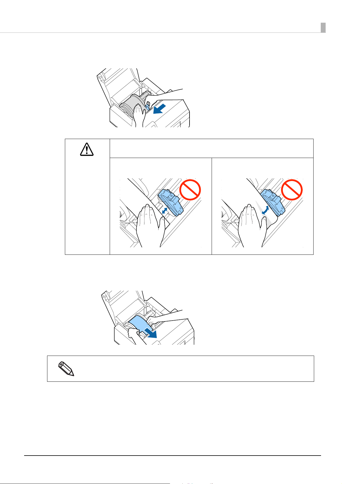
Place your hand on the paper to flatten it, and slide the movable edge guide against
8
the paper.
If the movable edge guide is not properly slided against the paper, print position may
become incorrect or a paper jam may occur. Make sure to follow the guidelines below.
Chapter2 Setup
CAUTION
Insert the paper into the paper feed slot until paper feeding starts automatically.
9
Do not load backing paper that has no labels on it. The paper may not be detected and not be fed
automatically.
• There should be no gap between the
guide and the paper edge.
• Do not slide the guide against the paper
too tightly.
If you are using special paper, the paper may not be fed into printer automatically because the printer
can fail to detect the paper. To feed the paper into the printer manually, see "Feeding Paper into the
Printer Manually" on page 68.
60
Page 61

Chapter2 Setup
10
11
Rotate the spindle to remove looseness in the paper.
Close the paper cover.
12
13
Hold down the [Feed] button until the leading edge of paper touches the table on
which the printer is installed.
Remove labels from the ejected paper.
61
Page 62

Chapter2 Setup
Peeler slot
14
15
Open the peeler cover.
Do not touch the manual cutter at the bottom of the peeler cover with your hand. Doing so may
cause injury. ("Caution Label" on page 10)
Pass the paper through the peeler slot.
16
17
Close the peeler cover.
If the paper is loose, pull the leading edge of paper to remove the looseness and then close the
peeler cover.
Press the [Pause] button.
Loading paper (peeler model - supply from inside) is now completed.
62
Page 63

How to Remove Paper (For the Auto Cutter Model)
Check that the printer has been turned on.
1
Press the [Cut] button, and cut off the ejected labels.
2
Press the [Back Feed] button to feed the paper backward.
3
The paper can now be pulled out from inside the printer.
Chapter2 Setup
Open the paper cover.
4
Slide the movable edge guide away from the paper, and remove the paper.
5
Removing the paper is now completed.
To load paper, see the following pages.
"How to Load Paper (Auto Cutter Model - Supply from Inside)" on page 50, "How to Load Paper (Auto Cutter
M
odel - Supply from Outside)" on page 54
63
Page 64

How to Remove Paper (For the Peeler Model)
Check that the printer has been turned on.
1
Open the peeler cover.
2
Cut the backing paper near the paper ejection slot.
3
Chapter2 Setup
Press the [Back Feed] button to feed the paper backward.
4
The paper can now be pulled out from inside the printer.
Open the paper cover.
5
64
Page 65

Slide the movable edge guide away from the paper, and remove the paper.
6
Removing the paper is now completed.
To load paper, see the following pages.
"How to Load Paper (Peeler Model - Supply from Inside)" on page 58
Chapter2 Setup
65
Page 66

Chapter2 Setup
How to Eject Paper at Paper End (For the Auto Cutter Model)
Hold down the Feed button until the paper is completely ejected.
1
Ejecting paper at paper end is now completed.
To load paper, see the following pages.
"How to Load Paper (Auto Cutter Model - Supply from Inside)" on page 50, "How to Load Paper (Auto Cutter
M
odel - Supply from Outside)" on page 54
66
Page 67

How to Eject Paper at Paper End (For the Peeler Model)
Peeler slot
Open the peeler cover.
1
Remove the paper from the peeler slot.
2
Chapter2 Setup
Hold down the Feed button until the paper is completely ejected.
3
Ejecting paper at paper end is now completed.
To load paper, see the following pages.
"How to Load Paper (Peeler Model - Supply from Inside)" on page 58
67
Page 68

Chapter2 Setup
Feeding Paper into the Printer Manually
If you are using special paper, the paper may not be fed into the printer automatically because the printer can
fail to detect the paper. In such case, follow the procedure below to feed the paper manually.
If this manual feeding method is used, the printer operation and print quality are not guaranteed.
CAUTION
Advance the paper with your hand until the leading edge comes in contact with the
1
paper feed shaft.
Hold down the paper with your hand and press the Feed button.
2
68
Page 69

Test Print
Normal
Clogging
Example o
f the nozzle check patterns with gloss black ink
You can check whether the printer operates normally or not by printing a nozzle check patterns.
Follow the procedure below to print the nozzle check patterns. The nozzle check patterns allow you to check
print nozzles for clogging.
Turn the printer on.
1
Select [Menu] and then press the [OK] button.
2
Select [Maintenance].
3
Select [Print Head Nozzle Check].
4
Select [Print].
5
The nozzle check patterns are printed.
Chapter2 Setup
Checking the Nozzle Check Patterns
6
If the pattern is printed normally, all the lines are printed properly as shown in the left figure below.
Nozzles are clogging if there are missing lines as shown in the right figure below. Run the print head
cleaning.
69
Page 70

Test Print using the Printer Driver
If you have already installed the printer driver, you can do a test print using the printer driver.
Follow the procedure below to do the test print.
Open [Devices and Printers].
1
Right-click the icon of the printer, and then click [Printer properties].
2
The Printer properties screen appears. Click [Print Test Page] on the screen.
3
Chapter2 Setup
If the [Media Detect] setting has been set to [Gap], the test page is not printed from the first label.
However, the auto cutter model can print from the first label if you do the settings described in
the link below. ("Printing from the First Label (Auto cutt
er model only)" on page 240)
70
Page 71

Chapter3 Handling
Handling
This chapter provides basic information necessary for handling the printer.
Printer Driver for Windows
This chapter describes how to operate the printer driver for Windows.
The printer driver is software to control the printer in accordance with the print instructions of application
software. Setting the print settings in the printer driver screen enables you to obtain the best print results.
Furthermore, you can also use the utilities to check the printer status and perform maintenance.
71
Page 72

Chapter3 Handling
Printer Driver Screen Configuration
The printer driver is equipped with a help function. Right-click an item and then click Help to display an
explanation on the item.
1 Current Settings pane
Displays a summary of current settings.
2 General tab
Lets you set media (paper) size, media form, and other basic print settings.
3 Options tab
Print orientation and the number of copies can be set.
4 Driver Utilities tab
Lets you configure various advanced settings.
5 Printer Utilities tab
Lets you run printer maintenance functions such as print head cleaning or nozzle check, and start PrinterSetting.
72
Page 73

Paper Source and Paper Detection Settings
Open the printer driver window.
1
Click [Media Detection...] on the General tab.
2
Chapter3 Handling
73
Page 74

Make the following settings to match them with the paper you use.
3
Chapter3 Handling
• Media Source: Select how to supply paper to the printer.
Setting item Description
Internal roll (supply from Inside) Paper is supplied from inside the
printer. Set roll paper attached to
the spindle into the printer.
External feed (supply from
outside)
Paper is supplied from outside
the printer. Place roll paper or
fanfold paper behind the printer.
• Media detection: Select how to detect print positions.
Setting item Description
Gap detection The print position is detected based on the gaps between labels.
Black mark detection The print position is detected based on the black marks printed on the back or
backing paper of the paper.
No detection Print position detection using gaps or black marks is not performed.
74
Page 75

Chapter3 Handling
Click [OK].
4
Paper source and paper detection settings are now complete.
User-Defined Paper
The size, form, type, and other settings of frequently used paper can be registered to the printer driver as a
media definition. This is convenient because you will not need to set the paper settings of the driver when
printing from an application if you register a media definition in advance.
If you wish to set the paper size and other settings every time without registering a media definition,
select [Custom] from the [Media Name] pull-down menu on the [General] tab. The various settings on
the [General] tab will become available so that you can set the paper size and other settings.
Registering New
Register a new media definition by following the steps below.
Open the printer driver window.
1
Click the [Media Definition] button on the [General] tab.
2
The Media Definition screen appears.
75
Page 76

Click the [New] button.
3
The New screen appears.
Chapter3 Handling
Make the following settings to match them with the paper you use.
4
1 Media Name
Enter the name of the media definition.
This is the name displayed when you select a paper size from an application.
76
Page 77

2 Label width
Enter the width of the label.
• Continuous label: label width excluding the backing paper
• Die-cut label: Label width excluding backing paper
Chapter3 Handling
3 Label length
Enter the length of the label.
• Continuous label: Length of the print range (length of one page)
• Die-cut label: Label length excluding backing paper
4 Gap between labels
Enter the gap between labels.
5Media Form
Select the form of the paper. ("Paper Specifications" on page 313)
77
Page 78

6 Media Saving (for continuous label only)
c
IMPORTANT
If the print data includes barcode font replacement data, the [Media Saving] setting
such as [Eliminate Lower Margin] and [Eliminate Lower and Upper Margin] is
ignored.
Top mar gin
Print data
Bottom margin
Paper feed direction
If you set the printer to cut paper in the [Settings for Paper Handling After Print]
setting, paper length of at least 15 mm is required. When the length of print data is less
than 15 mm, the margins are not eliminated even if you have set to [Eliminate Lower
Margin] or [Eliminate Lower And Upper Margin].
If your print data includes labels of various sizes, paper length to print each of the
labels can be optimized by setting the largest label size as the label (page) size, and
using the [Media Saving] function.
Print data length
Margin
Minimum paper length:
15 mm
Select a media saving setting. The [Media Saving] function eliminates margins from one-page print data
to suppress wasting paper.
• No Saving: Paper is advanced before and after printing causing top and bottom margins on the
printout.
• Eliminate Lower Margin: Paper is not advanced after printing to eliminate bottom margin from the
printout.
• Eliminate Lower and Upper Margin: Paper is not advanced before and after printing to eliminate both
top and bottom margins from the printout.
Chapter3 Handling
7Media Type
Select the paper type. ("Paper Specifications" on page 313)
78
Page 79

8 Print Quality
c
IMPORTANT
Supported paper types vary depending on which type of black ink, gloss black or
matte black, is installed. See "Paper Specifications" on page 313.
If you change the [Media Type] setting, the [Print Quality] setting will automatically be
set to the initial setting suitable for the selected paper type.
Click [Advanced] to configure more detailed print quality settings.
Select the print quality.
When [Media Type] is [Plain Paper]
• High Speed: 300 x 600 dpi
• Speed: 600 x 600 dpi (initial setting)
• Standard: 600 x 600 dpi
• Quality: 600 x 1200 dpi
When [Media Type] is [Texture Paper], [Matte Paper] or [Synthetic]
• High Speed: 300 x 600 dpi
• Speed: 600 x 600 dpi
• Standard: 600 x 600 dpi (initial setting)
• Quality: 600 x 1200 dpi
When [Media Type] is [Glossy Paper], [Glossy Film], or [High Glossy Paper]
• Standard: 600 x 600 dpi
• Quality: 600 x 1200 dpi (Initial setting)
• Max Quality: 1200 x 1200 dpi
Chapter3 Handling
9 Color Correction Mode
Configure color correction settings. For more details about the color correction, see "Color Correction" on
page 227.
• V
ivid colors: click [Color Correction] to customize the color settings.
• ICM: click [Color Correction] to select an ICC profile.
• No composite: no color correction is applied.
10 Spot Color Setting
Select a spot color setting file. For more details about the spot color setting, see "Spot Color Settings" on
page 221.
79
Page 80

11 Settings For Paper Handling After Print
c
IMPORTANT
If you have set to [Cut (after last page of collate page)] and if the printer stops due
to a paper jam or other reason while the auto cutter is operating, it is impossible to
resume printing.
• If you change the settings in [Print Color Adjustment], and/or [Bar Width
Adjustment], it may affect readability of barcodes.
• If you increase the ratio of black ink in [Ratio of Black to Composite], be careful not
to touch the label surface immediately after printing because ink can adhere to your
fingers.
For the Auto Cutter Model
• Cut (after printing last label)
• Cut (at specified label)
• Cut (after last page of collate page)
• Do not cut (stop at cut position) (Initial setting)
• Do not cut (stop at peel position)
• Do not cut (stop at the print end position)
For the Peeler Model
• Manual apply (Initial setting)
• Auto apply
• Rewind
12 Advanced
Chapter3 Handling
Change the settings for color, barcode, and paper handling. For more details about each menu item, see
the Help.
• Print Color Adjustment
Ink Profile: Print density can be changed to darker or lighter.
Ratio of Black to Composite: Adjust the ratio of black ink to composite black.
• Barcode and 2D Symbol Preset
Bar Width Adjustment: When using a built-in barcode font, adjust the bar width.
• Paper Adjustment
Platen Vacuum Manual Adjustment: Adjust the paper suction power of the platen.
Drying time per head pass setting: Adjust additional time to dry ink.
80
Page 81

Click [OK].
5
Check that the registered media name is displayed in the Media Definition screen
6
and then click [Close].
Chapter3 Handling
Check that you can select the registered media name in [Media Name] on the
7
[General] tab.
Click the [OK] button to close the driver.
8
Paper registration (media definition) is now complete.
81
Page 82

Editing and Deleting
Open the printer driver window.
1
Click the [Media Definition] button on the [General] tab.
2
The Media Definition screen appears.
Chapter3 Handling
Click to select the media definition you wish to edit or delete.
3
82
Page 83

Chapter3 Handling
If you wish to change the definition settings, click the [Edit] button. The Edit screen
4
appears and you can change the definition.
If you wish to delete the definition, click the [Delete] button. A screen appears and if you click the
[OK] button, the definition is deleted.
Editing or deleting a media definition is now complete.
83
Page 84

Chapter3 Handling
Printing Barcodes
The printer has built-in fonts. This allows you to print a barcode without creating it on an application software.
Barcode Font Settings
You can make the barcode settings using [Barcode and 2D Symbol Settings] on the [Driver Utilities] tab.
Make the following settings.
1
•Display: Select [Barcodes].
• Font Name: Enter a character string. The string is set as the barcode font name. Only ASCII
characters are accepted.
• Type: Select a barcode type. Available setting items changes according to the selected
barcode type. You can select the type from the following options.
UPC-A UPC-E JAN13(EAN)
JAN8(EAN) Code39 ITF
Codabar(NW7) Code93 Code128
GS1-128 GS1 DataBar Omnidirectional GS1 DataBar Truncated
GS1 DataBar Limited GS1 DataBar Expanded
84
Page 85

Chapter3 Handling
• Rotation Settings: Select an option to rotate a barcode.
• Hexadecimal Input Mode:
Select the check box to enter data for a barcode in hexadecimal.
• Module: Specify the width of the narrowest element of the barcode in units of dot.
• Bar Height: Specify the height of the element in units of dot. Actual print size equivalent to
the specified dots will be displayed.
• HRI Character Position:
Specify the position to print HRI characters. Select [Do Not Print] if printing
HRI characters is not necessary.
Depending on the selected barcode type, the position option cannot be selected.
• Composite Component:
Select a composite type.
• Element Ratio: Specify the ratio of wide element width to the narrowest element width.
The recommended ratio is 2.5.
• Check Digit: A number or symbol added to the barcode number in order to detect an error in
the barcode number and to prevent fabrication.
• Auto Convert to Minimize Entire Symbol Width:
You can select this when the barcode type is CODE128. This function minimizes
the number of symbols and characters that are necessary to express the specified
data string.
• Start Character: Specify the start character.
• Stop Character: Specify the stop character.
Click [Add].
2
The configured barcode font is registered and added to the font list.
• Up to 30 barcode fonts can be registered.
• To edit settings of a registered barcode font, select the font from the font list, change the
settings and then click [Save].
• To delete a registered barcode font, select the font from the font list, and then click [Delete].
85
Page 86

Chapter3 Handling
Paper width direction
Paper feed direction
Paper width direction
Paper feed direction
Fence barcode
Ladder barcode
Recommended Module Values
Print directions of a barcode are as shown below. The recommended module values vary by paper type, barcode
type, and the print direction.
If [Rotation Settings] is set to [Normal] or [Rotate 270 Degrees], the barcode is not be printed.
WARNING
❏ 300 dpi
Minimum module size [in units of 300 dpi]
ANSI
Grade D
Barcode Orientation
Code39Fence433333
Ladder533333
CodabarFence433333
Ladder533333
Code93Fence433333
or higher
Plain
Paper
Matte
Paper
ANSI Grade C or higher
Syn-
thetic
Glossy
Paper
Glossy
Film
High
Glossy
Paper
Code128Fence433333
GS1-128Fence433333
ITF Fence433333
Ladder533333
Ladder533333
Ladder533333
Ladder533333
86
Page 87

Barcode Orientation
ANSI
Grade D
or higher
Chapter3 Handling
Minimum module size [in units of 300 dpi]
ANSI Grade C or higher
Plain
Paper
GS1 DataBar
Omnidirectio
nal
GS1 DataBar
Tru ncate d
GS1 DataBar
Limited
GS1 DataBar
Expanded
UPC-AFence433333
UPC-ELadder533333
JAN13Fence433333
JAN8Ladder533333
EAN13Fence433333
Fence433333
Ladder533333
Fence433333
Ladder533333
Fence433333
Ladder533333
Fence433333
Ladder533333
Matte
Paper
Syn-
thetic
Glossy
Paper
Glossy
Film
High
Glossy
Paper
EAN8Ladder533333
❏ 600 dpi
Minimum module size [in units of 600 dpi]
ANSI
Grade D
Barcode Orientation
Code39Fence755555
Ladder1065666
CodabarFence755555
Ladder1065666
Code93Fence755555
Ladder1065666
Code128Fence755555
Ladder1065666
or higher
Plain
Paper
Matte
Paper
ANSI Grade C or higher
Syn-
thetic
Glossy
Paper
Glossy
Film
High
Glossy
Paper
87
Page 88

Barcode Orientation
ANSI
Grade D
or higher
Chapter3 Handling
Minimum module size [in units of 600 dpi]
ANSI Grade C or higher
Plain
Paper
GS1-128 Fence 7 5 5 5 5 5
adder1065666
L
ITF Fence766666
Ladder1066666
GS1 DataBar
Omnidirectio
nal
GS1 DataBar
Tru ncate d
GS1 DataBar
Limited
GS1 DataBar
Expanded
UPC-AFence777777
UPC-ELadder1077777
Fence766666
Ladder1066666
Fence766666
Ladder1066666
Fence766666
Ladder1066666
Fence766666
Ladder1066666
Matte
Paper
Syn-
thetic
Glossy
Paper
Glossy
Film
High
Glossy
Paper
JAN13Fence777777
JAN8Ladder1077777
EAN13Fence777777
EAN8Ladder1077777
• Readability of a barcode varies by paper type, performance of a barcode reader, or other factors.
Furthermore, drop in print quality due to clogging of print head nozzles or skew of ink drops can
cause a barcode to become unreadable. In case it happens, it is recommended to print HRI
characters or take other measures.
• Due to characteristic of ink, ink seeped into paper may cause the bars of a barcode to be printed
thicker. In such cases, carry out [Bar Width Adjustment] that reduces the bar width by 2 pixels,
and increases space width by 2 pixels.
• If vibrations or shocks are applied to the printer during transporting or installing the printer, it
may cause drop in barcode rank. In that happens, barcode rank may improve by carrying out
[Bi-directional Printing Adjustment]. ("Bi-directional Printing Adjustment" on page 186)
88
Page 89

Chapter3 Handling
How to Specify Barcode Data
See the following descriptions to specify barcode data.
About the composite symbol:
Switching between CC-A and CC-B is automatically performed, however, to use CC-C, you need to specify to
use it.
(For GS1-128, the type of composite component can be selected from [No composite], [CC-A/CC-B], and [CCC].)
Composite component type Encodable number of digits
CC-A 1 to 56 digits
CC-B 1 to 338 digits
CC-C 1 to 2361 digits
About HRI characters:
If the length of the HRI characters becomes wider than entire width of the barcode, the length is regarded as
the barcode width.
UPC-A
• Specify the barcode data with 11 digits. A check digit will be automatically added.
UPC-E
• Specify the barcode data with 10 digits. 5 digits are for a manufacturer code, and the rest of 5 digits are for a
product code.
JAN13(EAN)
• Specify the barcode data with 12 digits. A check digit will be automatically added.
JAN8(EAN)
• Specify the barcode data with 7 digits. A check digit will be automatically added.
Code39
• If both or either one of a start code or a stop code is not specified, they will be automatically added.
ITF
• If specified with an odd number of digits, “0” (zero) will be automatically added at the beginning of the
digits.
Codabar(NW7)
• Do not include a start code and a stop code. The start code and stop code you specified on the printer driver
will be added.
89
Page 90

Code93
• A start code, two check digits, and a stop code will be automatically added.
• A character () that indicates a start code is printed at the beginning of the HRI characters.
character () that indicates a stop code is printed at the end of the HRI characters.
• A
Chapter3 Handling
• A co
mbination of
■ and an alphabet character is printed to express each of HRI control characters (00h to
1Fh, 7Fh).
Control character
ASCII
NULL 00 ■ U VT 0B ■ K SYN 16 ■ V
SOH 01 ■ A FF 0C ■ L ETB 17 ■ W
STX 02 ■ B CR 0D ■ M CAN 18 ■ X
ETX 03 ■ C SO 0E ■ N EM 19 ■ Y
EOT 04 ■ D SI 0F ■ O SUB 1A ■ Z
ENQ 05 ■ E DLE 10 ■ P ESC 1B ■ A
ACK 06 ■ F DC1 11 ■ Q FS 1C ■ B
BEL 07 ■ G DC2 12 ■ R GS 1D ■ C
BS 08 ■ H DC3 13 ■ S RS 1E ■ D
HT 09 ■ I DC4 14 ■ T US 1F ■ E
Hex
number
HRI
charac-
ter
Control character
ASCII
Hex
number
HRI
charac-
ter
Control character
ASCII
number
Hex
HRI
charac-
ter
LF 0A ■ J NAK 15 ■ U DEL 7F ■ F
90
Page 91

Chapter3 Handling
Code128
• If you have disabled the auto convert function, enter a two-digits start code at the beginning of the data. If
you have enabled the auto convert function, the type of start character is automatically determined and you
do not need to specify the type in your application.
• An error will occur if you add {A, which sets the type to CODE A, when CODE A has already been selected as the start
character.
• An error will occur if you add {B, which sets the type to CODE B, when CODE B has already been selected as the start
character.
• An error will occur if you add any one of the following characters when CODE C has already been selected as the start
character.
{S {C {2 {3 {4 {{
• A special character is expressed by a combination of { and the next character.
Control character ASCII HRI character
SHIFT {S Not printed
CODE A {A Not printed
CODE B {B Not printed
CODE C {C Not printed
FNC1 {1 Not printed
FNC2 {2 Not printed
FNC3 {3 Not printed
FNC4 {4 Not printed
‘{‘ {{ { is printed.
91
Page 92

Chapter3 Handling
GS1-128
• ‘()’ are used as delimiters for the application identifiers. (printed as the HRI character, but not encoded.)
• A start code (CODE A, CODE B, CODE C) and a stop code will be automatically added.
• A symbol character FNC1 is automatically added next to the start code.
• If you use “*”, it will be skipped.
• As an application identifier, specify a two-digits consecutive number. If the identifier is not specified
correctly, an error will occur.
• A special character is expressed by a combination of { and the next character.
• If data immediately after { does not apply to any one of the followings, an error will occur.
Control character ASCII HRI character
Control character (00h to 1Fh, and 7Fh) A space is printed.
FNC1 {1 A space is printed.
'{' {{ { is printed.
'(' {( ( is printed.
')' {) ) is printed.
'*' {* * is printed.
Beginning parenthesis for an application identifier ( ( is printed.
Closing parenthesis for an application identifier ) ) is printed.
Skipped character * Not printed
GS1 DataBar Omnidirectional / GS1 DataBar Truncated / GS1 DataBar Limited
• The first “01”, an application identifier, is not encoded (not included as the barcode data).
• When the HRI character is printed, the application identifier 01 is printed as “(01)” before the package
identification code.
• You do not need to add a check digit in the barcode data.
• When the HRI character is printed, a check digit will be automatically printed after the product code.
• For GS1 DataBar Limited, specify 0 or 1 for the first digit.
92
Page 93

Chapter3 Handling
GS1 DataBar Expanded
• ‘()’ are used as delimiters for the application identifiers. (printed as the HRI character, but not encoded.)
• Be sure to include all the application identifiers in the data.
• If the first data is “01” when an application identifier, left and right parentheses, and * are excluded, the 14th
digit counted from the digit next to “01” is used as the check digit. If the data is incorrect, an error will occur.
• If the number of digits after “01” is less than 14, a check digit is not added.
(Unlike GS1-128, a symbol “*” cannot be used for automatic calculation and addition of a check digit. If “*” is
added in the data, it will be ignored and the subsequent data is shifted by one digit.)
• Specify a special character as described below.
Control character ASCII HRI character
FNC1 {1 Not printed
Beginning parenthesis for an application
identifier
Closing parenthesis for an application
identifier
'*' {* Error
Skipped character * Not printed
'{' {{ { is printed.
( ( is printed.
) ) is printed.
93
Page 94

Chapter3 Handling
How to Print
Open print data file in an application, and specify barcode font, point, and language that you have set on the
printer driver, and then print it.
• The barcode size cannot be changed from the point set in [Specified Point]. If you specify a size other
than the specified one, the barcode is not printed.
• Some application such as .NET application may not be able to display or let you select the barcode
font registered by the printer driver. If that occurs, use the [Font Replacement] function of the printer
driver to replace a True Type font with the barcode font. See "Printing Barcodes / 2D Symbols on .NET
Environment" on page 103.
94
Page 95

Chapter3 Handling
Printing 2D Symbols
The printer driver has the built-in 2D symbol font. This allows you to print a 2D symbol without creating it on
an application software.
Setting the 2D Symbol Font
You can make the 2D symbol settings using [Barcode and 2D Symbol Settings] on the [Driver Utilities] tab.
Make the following settings.
1
•Display: Select [2D Symbols].
•Font Name: Enter a character string. The string is set as the 2D symbol font name. Only ASCII
characters are accepted.
•Type: Select a type of 2D symbol. Available setting items changes according to the selected type.
•Rotation Settings: Select an option to rotate a 2D symbol.
•Hexadecimal Input Mode: Select the check box to enter data for a 2D symbol in hexadecimal.
95
Page 96

Make the settings for the barcode type you selected.
2
• Settings for PDF417
∗ Module Width: Set module width of PDF417.
For the recommended value, see "Recommended Module Values" on page 98.
odule Height: Specify the ratio of PDF417 module height to the module width.
∗ M
For the recommended value, see "Recommended Module Values" on page 98.
olumn: Specify the number of columns of PDF417.
∗ C
∗ Row: Specify the number of rows of PDF417.
∗ Truncat i on Sy m bo l :
Select the check box to create a symbol using data excluding the stop code of
PDF417.
∗ Error Correction Level
Specify an error correction level for PDF417. This allows the symbol data to be
correctly read even if a portion of the symbol is missing or damaged. The larger
the number is, the higher the possibility of data restoration gets.
• Settings for MicroPDF417
∗ Module Width: Set module width of MicroPDF417.
For the recommended value, see "Recommended Module Values" on page 98.
odule Height: Specify the ratio of MicroPDF417 module height to the module width.
∗ M
For the recommended value, see "Recommended Module Values" on page 98.
olumn: Specify the number of columns of MicroPDF417.
∗ C
∗ Row: Specify the number of rows of MicroPDF417.
Chapter3 Handling
•Settings for QR code
∗ Model: Select a QR code model.
∗ Module: Select a width of a cell (module) of QR code.
For the recommended value, see "Recommended Module Values" on page 98.
ror Correction Level:
∗ Er
Specify an error correction level for QR code. This allows the symbol data to be
correctly read even if a portion of the symbol is missing or damaged. The possibility of data restoration gets higher in the order of L, M, Q, and H.
∗ Character Mode: Select a mode for data to be converted into a QR code.
• Settings for Micro QR code
∗ Version: Specify the version of Micro QR code.
∗ Module: Select a width of a cell (module) of Micro QR code.
For the recommended value, see "Recommended Module Values" on page 98.
ror Correction Level:
∗ Er
Specify an error correction level for Micro QR code. This allows the symbol data
to be correctly read even if a portion of the symbol is missing or damaged. The
possibility of data restoration gets higher in the order of L, M.
•Settings for MaxiCode
∗ Mode: Select a mode of MaxiCode.
• Settings for GS1 DataBar
∗ Module: Set module width of GS1 DataBar.
For the recommended value, see "Recommended Module Values" on page 98.
umber of Characters: Specify the max width of GS1 DataBar.
∗ N
Set this if you have selected GS1 DataBar Expanded Stacked.
96
Page 97

• Settings for AztecCode
∗ Type: Select a type of AztecCode.
∗ Cell Size: Select a size of a cell (module) of AztecCode.
For the recommended value, see "Recommended Module Values" on page 98.
umber of Layers: Specify the number of layers of AztecCode.
∗ N
∗ Error Correction Area:
Select any one of the following error correction area settings for AztecCode. This
allows the symbol data to be correctly read even if a portion of the symbol is
missing or damaged. The larger the number is, the higher the possibility of data
restoration gets.
[Auto]: the default is 23%+3 code words.
[Specify a Percentage]: Enter a percentage of error correction area into the entry
field.
• Settings for DataMatrix
∗ Symbol Shape: Select a shape of DataMatrix symbol.
∗ Error Correction Level:
Specify an error correction level for DataMatrix.
∗ Cell Size: Select a size of a cell (module) of DataMatrix.
For the recommended value, see "Recommended Module Values" on page 98.
mber of Vertical Cells:
∗ Nu
Specify the number of cells of DataMatrix in the vertical direction.
Set this when you have selected [Rectangle] in the DataMatrix [Symbol Shape]
setting.
∗ Number of Horizontal Cells:
Specify the number of cells of DataMatrix in the horizontal direction.
Set this when you have selected [Rectangle] in the DataMatrix [Symbol Shape]
setting.
[Minimize]: The number of cells is automatically optimized and minimized.
[Specify the Size]: The number of cells is set according to the selected size.
Chapter3 Handling
Click [Add].
3
The configured 2D symbol font is registered and added to the font list.
• Up to 30 2D symbol fonts can be registered.
• To edit settings of a registered 2D symbol font, select the font from the font list, change the
settings and then click [Save].
• To delete a registered 2D symbol font, select the font from the font list, and then click [Delete].
97
Page 98

Recommended Module Values
The recommended module values vary by paper type, 2D symbol type, and the print direction.
• You cannot change the orientation of a QR code, Micro QR code, and Maxi code by setting
[Orientation] on the [Options] tab to [Landscape].
CAUTION
2D Symbols - Stacked code type
❏ 300 dpi
2D Symbols Orientation
• You cannot rotate a QR code, Micro QR code, and Maxi code by selecting [Rotate 180] on the
[Options] tab. In addition, if [Rotation Settings] is set to [Normal] or [Rotate 270 Degrees], the 2D
symbol is not be printed.
Minimum module size [in units of 300 dpi]
ANSI
Grade D
ANSI Grade C or higher
or higher
Chapter3 Handling
Plain
Paper
PDF417- 533333
Micro PDF- 533333
GS1 DataBar
Stacked
GS1 DataBar
Stacked
Omnidirectional
GS1 DataBar
Expanded
Stacked
- 533333
- 533333
- 533333
Matte
Paper
Syn-
thetic
Glossy
Paper
Glossy
Film
❏ 600dpi
Minimum module size [in units of 600 dpi]
ANSI
2D Symbols Orientation
Grade D
or higher
ANSI Grade C or higher
High
Glossy
Paper
Plain
Paper
PDF417 - 10 5 5 5 5 5
Micro PDF- 1055555
GS1 DataBar
Stacked
- 1055555
Matte
Paper
Syn-
thetic
Glossy
Paper
Glossy
Film
High
Glossy
Paper
98
Page 99

2D Symbols Orientation
ANSI
Grade D
or higher
Chapter3 Handling
Minimum module size [in units of 600 dpi]
ANSI Grade C or higher
GS1 DataBar
Stacked
Omnidirectional
GS1 DataBar
Expanded
Stacked
Plain
Paper
- 1055555
- 1055555
• If vibrations or shocks are applied to the printer during transporting or installing the printer, it
may cause drop in barcode rank. In that happens, barcode rank may improve by carrying out [Bidirectional Printing Adjustment]. ("Bi-directional Printing Adjustment" on page 186)
Matte
Paper
Syn-
thetic
Glossy
Paper
Glossy
Film
High
Glossy
Paper
99
Page 100

2D Symbols - Matrix code type
❏ 300 dpi
2D Symbols Orientation
ANSI
Grade D
or higher
Chapter3 Handling
Minimum module size [in units of 300 dpi]
ANSI Grade C or higher
Plain
Paper
QR Code- 745555
Micro QR- 756555
Aztec - 744444
DataMatrix- 734333
MaxiCode- 212121212121
Matte
Paper
Syn-
thetic
Glossy
Paper
Glossy
Film
❏ 600dpi
Minimum module size [in units of 600 dpi]
ANSI
2D Symbols Orientation
Grade D
or higher
Plain
Paper
Matte
Paper
ANSI Grade C or higher
Syn-
thetic
Glossy
Paper
Glossy
Film
High
Glossy
Paper
High
Glossy
Paper
QR Code- 13910999
Micro QR - 13 11 12 11 11 11
Aztec - 1388888
DataMatrix- 1378777
MaxiCode - 21 21 21 21 21 21
• If vibrations or shocks are applied to the printer during transporting or installing the printer, it
may cause drop in barcode rank. In that happens, barcode rank may improve by carrying out
[Bi-directional Printing Adjustment]. ("Bi-directional Printing Adjustment" on page 186)
100
 Loading...