

Page 1
SERVICE MANUAL
Color Laser Page Printer
EPSON AcuLaser C4000
AcuLaser C4100
AcuLaser C3000
SEPG01012
Page 2

Notice
All rights reserved. No part of this manual may be reproduced, stored in a retrieval system, or transmitted in any form or by any means electronic,
mechanical, photocopying, or otherwise, without the prior written permission of SEIKO EPSON CORPORATION.
The contents of this manual are subject to change without notice.
All effort have been made to ensure the accuracy of the contents of this manual. However, should any errors be detected, SEIKO EPSON would
greatly appreciate being informed of them.
The above not withstanding SEIKO EPSON CORPORATION can assume no responsibility for any errors in this manual or the consequences
thereof.
EPSON is a registered trademark of SEIKO EPSON CORPORATION.
General Notice: Other product names used herein are for identification purpose only and may be trademarks or registered trademarks of their
respective owners. EPSON disclaims any and all rights in those marks.
Copyright © 2004 SEIKO EPSON CORPORATION.
Imaging & Information Product Division
CS/Quality Management & PL Department
Page 3

PRECAUTIONS
Precautionary notations throughout the text are categorized relative to 1) Personal injury and 2) damage to equipment.
DANGER Signals a precaution which, if ignored, could result in serious or fatal personal injury. Great caution should be exercised in
performing procedures preceded by DANGER Headings.
WARNING Signals a precaution which, if ignored, could result in damage to equipment.
The precautionary measures itemized below should always be observed when performing repair/maintenance procedures.
DANGER
1. ALWAYS DISCONNECT THE PRODUCT FROM THE POWER SOURCE AND PERIPHERAL DEVICES PERFORMING ANY MAINTENANCE OR REPAIR
PROCEDURES.
2. NO WORK SHOULD BE PERFORMED ON THE UNIT BY PERSONS UNFAMILIAR WITH BASIC SAFETY MEASURES AS DICTATED FOR ALL ELECTRONICS
TECHNICIANS IN THEIR LINE OF WORK.
3. WHEN PERFORMING TESTING AS DICTATED WITHIN THIS MANUAL, DO NOT CONNECT THE UNIT TO A POWER SOURCE UNTIL INSTRUCTED TO DO
SO. WHEN THE POWER SUPPLY CABLE MUST BE CONNECTED, USE EXTREME CAUTION IN WORKING ON POWER SUPPLY AND OTHER ELECTRONIC
COMPONENTS.
4. WHEN DISASSEMBLING OR ASSEMBLING A PRODUCT, BE SURE TO WEAR GLOVES TO AVOID INJURIES FROM METAL PARTS WITH SHARP EDGES.
WARNING
1. REPAIRS ON EPSON PRODUCT SHOULD BE PERFORMED ONLY BY AN EPSON CERTIFIED REPAIR TECHNICIAN.
2. MAKE CERTAIN THAT THE SOURCE VOLTAGES IS THE SAME AS THE RATED VOLTAGE, LISTED ON THE SERIAL NUMBER/RATING PLATE. IF THE
EPSON PRODUCT HAS A PRIMARY AC RATING DIFFERENT FROM AVAILABLE POWER SOURCE, DO NOT CONNECT IT TO THE POWER SOURCE.
3. ALWAYS VERIFY THAT THE EPSON PRODUCT HAS BEEN DISCONNECTED FROM THE POWER SOURCE BEFORE REMOVING OR REPLACING
PRINTED CIRCUIT BOARDS AND/OR INDIVIDUAL CHIPS.
4. IN ORDER TO PROTECT SENSITIVE MICROPROCESSORS AND CIRCUITRY, USE STATIC DISCHARGE EQUIPMENT, SUCH AS ANTI-STATIC WRIST
STRAPS, WHEN ACCESSING INTERNAL COMPONENTS.
5. DO NOT REPLACE IMPERFECTLY FUNCTIONING COMPONENTS WITH COMPONENTS WHICH ARE NOT MANUFACTURED BY EPSON. IF SECOND
SOURCE IC’S OR OTHER COMPONENTS WHICH HAVE NOT BEEN APPROVED ARE USED, THEY COULD CAUSE DAMAGE TO THE EPSON PRODUCT,
OR COULD VOID THE WARRANTY OFFERED BY EPSON.
Page 4

About This Manual
This manual describes basic functions, theory of electrical and mechanical operations, maintenance and repair procedures of the EPSON AcuLaser
C4000, AcuLaser C4100 and AcuLaser C3000. The instructions and procedures included herein are intended for the experienced repair technicians,
and attention should be given to the precautions on the preceding page.
Page 5
Manual Configuration
Symbols Used in this Manual
This manual consists of six chapters and Appendix.
CHAPTER 1. PRODUCT DESCRIPTIONS
Provides a general overview and specifications of the
product.
CHAPTER 2. OPERATING PRINCIPLES
Describes the theory of electrical and mechanical
operations of the product.
CHAPTER 3. TROUBLESHOOTING
Provides the step-by-step procedures for
troubleshooting.
CHAPTER 4. DISASSEMBLY AND ASSEMBLY
Describes the step-by-step procedures for
disassembling/assembling and adjusting the product.
CHAPTER 5 ADJUSTMENT
Provides Epson-approved methods for adjustment.
CHAPTER 6. MAINTENANCE
Provides preventive maintenance procedures and the
lists of Epson-approved lubricants and adhesives
required for servicing the product.
APPENDIX. Provides the following additional information for
reference:
• Connector pin assignments
• Electric circuit boards components layout
• Exploded diagram
• Electrical circuit boards schematics
Various symbols are used throughout this manual either to provide
additional information on a specific topic or to warn of possible danger
present during a procedure or an action. Be aware of all symbols when
they are used, and always read NOTE, CAUTION, or WARNING
messages.
A D J U S T M E N T
R E Q U I R E D
C A U T I O N
Indicates an operating or maintenance procedure, practice
or condition that is necessary to keep the product’s quality.
Indicates an operating or maintenance procedure, practice,
or condition that, if not strictly observed, could result in
damage to, or destruction of, equipment.
C H E C K
P O I N T
May indicate an operating or maintenance procedure,
practice or condition that is necessary to accomplish a task
efficiently. It may also provide additional information that is
related to a specific subject, or comment on the results
achieved through a previous action.
W A R N I N G
Indicates an operating or maintenance procedure, practice
or condition that, if not strictly observed, could result in
injury or loss of life.
Indicates that a particular task must be carried out
according to a certain standard after disassembly and
before re-assembly, otherwise the quality of the
components in question may be adversely affected.
Page 6

Abbreviation
This manual uses unique abbreviations and acronyms which may differ from those in common use. Please note that they are used in the manual
descriptions without explanation. The main abbreviations and acronyms are listed below. Because the following list was formed as a general
reference, some items on the list may not appear in this manual.
In principle most acronyms were formed from the capitalized first letters of the English term for the items (there are exceptions) and most single
word abbreviations were formed either will all capitals or with only the first letter as a capital.
[A]
ADC Auto Density Control
ALM Alarm
Assy Assembly
Aux. Auxiliary
[B]
B/W Black and White
BCR Bias Charge Roll
Bk Black
BCR Bias Charge Roll
BRKT Bracket
BTR Bias Transfer Roll
BUR Back Up Roll
[C]
CCyan
CCW Counter Clockwise
Cl. Clutch
Clk Clock
CHK Check
CK Check
Conpane Control Panel
Cont Controller
CR Charge Roll
CRU Customer Replaceable Unit
CRUM CRU Memory
CST Cassette
CVR Cover
CW Clockwise
[D]
DB Developing Bias
Deve Developer
Diag Diagnostic
dpi dots per inch
DTS Detack Saw
Dup Duplex
[E]
Elec Electric
EP Electro Photography
ESS Electric Sub System
[F]
F Front
FDR Feeder
FG Frame Ground
FIP Fault Isolation Procedure
FRU Field Replaceable Unit
FX Fuji Xerox
[G]
GG Guide Gauge
GND Ground
[H]
HHigh
H/R Heat Roll
HCF High Capacity Feeder
HCS High Capacity Stacker
Hex Hexadecimal
HVPS High Voltage Power Supply
[I]
I/F Interface
I/L Interlock
ID Image Density
[J]
Jxx Jack xx
Page 7

[L]
L Left
L Low
L/H Left Hand
L/P Low Paper
LD Laser Diode
LEF Long Edge Feed
LVPS Low Voltage Power
Supply
[M]
M Magenta
M/N Multi National
Mag Magnetic
MCU Machine Control Unit
Mech Mechanical
MOT Motor
MSI Multi Sheet Inserter
[N]
N/F Normal Force
N/P No Paper
NPS No Paper Sensor
NV Non Volatile
NVM Non Volatile Memory
[O]
OHP Overhead Projector
OPC Organic Photo Conductor
OPT Option
[P]
Pyy Plug yy
P/J Plug and Jack
P/H Paper Handling
P/R Pressure Roll
PL Plate
PLT Plate
PPM Print Per Minute
PV Print Volume
PWB Printed Wiring Board
PWBA PWB Assembly
[R]
R Right
R Rear
R/H Right Hand
RDY Ready
Regi Registration
ROS Raster Output Scanner
RRP Removal and Replacement
Procedure
RTN Return
[S]
SEF Short Edge Feed
SG Signal Ground
SNR Sensor
SNS Sensor
Sol Solenoid
SOS Start Of Scan
SPI Scan Per Inch
STD Stamdard
STK Stacker
STND Standard
SW Switch
Sync Synchronous
[T]
T Tooth (number of Gear)
Temp Temperature
TR Transfer
TTL Trangistor-Transistor Logic
[X]
Xero Xerographic
[Y]
YYellow
YMCBk Yellow/Magenta/Cyan/
Black
YMCK Yellow/Magenta/Cyan/
Black
Page 8
Safety Information
To prevent accidents during a maintenance procedure, strictly observe
the Warnings and Cautions. Do not do anything that is dangerous or not
within the scope of this document.
Do not do anything that is dangerous even if not specifically described
in this manual. In addition to the descriptions below and those given in
this manual, there are many situations and circumstances that are
dangerous. Be aware of these when you are working with the printer.
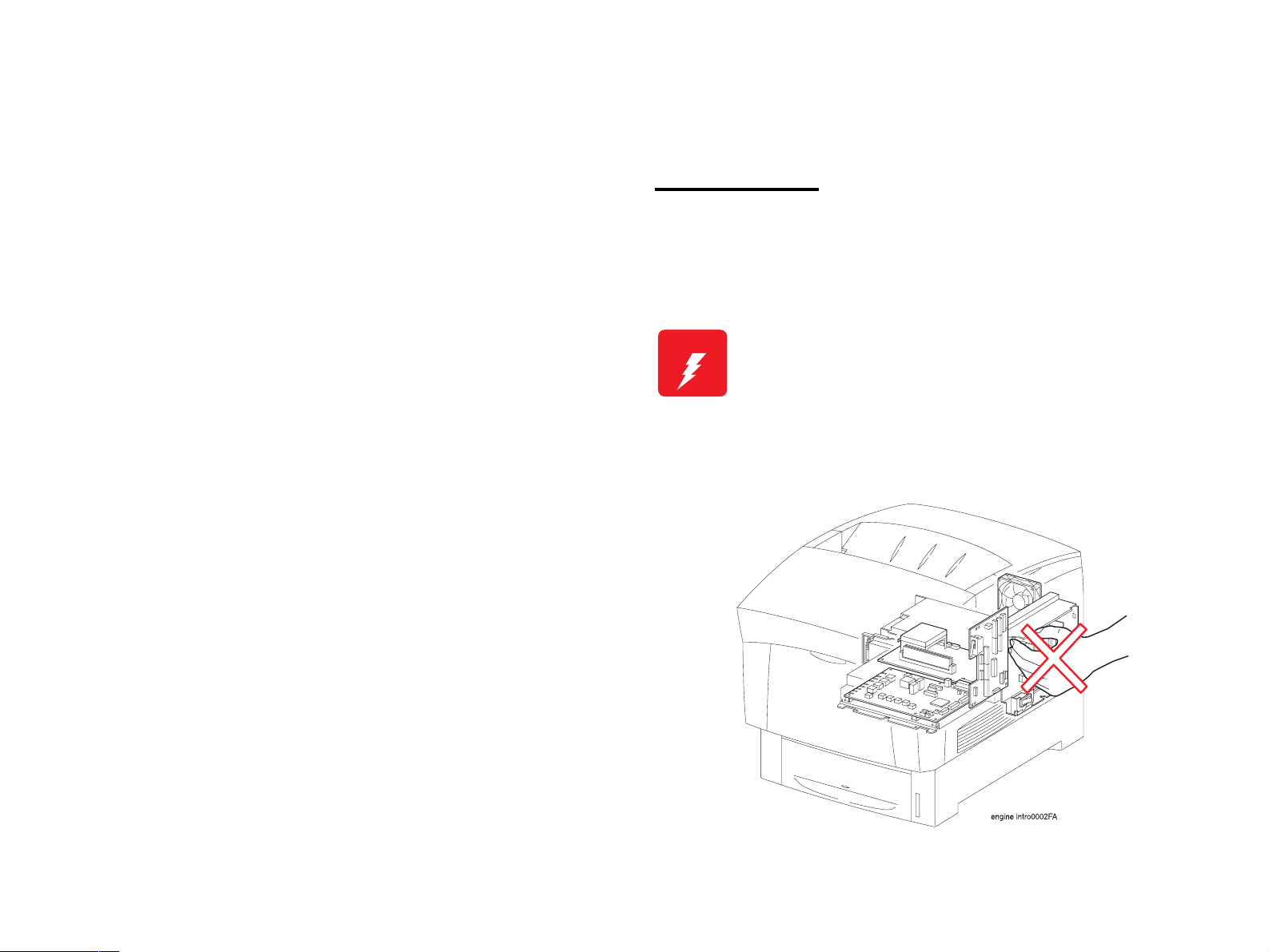
Power Supply
Before starting any service procedure, switch off the printer power and
unplug the power cord from the wall outlet. If you must service the
printer when the power is applied, be aware of the potential for electrical
shock and do all tasks by following the procedures in this manual.
W A R N I N G
Do not touch any live part unless you are instructed
to do so by a service procedure.
The LVPS power supply switch/inlet part is live even
when the power switch has been turned off. Do not
touch any live part.
Do not touch electrified components except when
instructions indicate it is permissible to do so.
Figure 0-1. Power Supply
Page 9

Mechanical Components
High Temperature Assembly
If you service a driving assembly (e.g., gears), first turn off the power
and unplug the power cord. Then manually rotate the assembly.
.
W A R N I N G
Do not touch the driving part (e.g., gears) while the
assembly (printer) is being driven.
To prevent you from becoming injured or burned, do the following:
Before working with a high temperature Assembly (e.g., Fuser
Assembly), turn off the power, unplug the power cord and wait until it
cools down.
W A R N I N G
The high temperature Assembly is very hot immediately
after any printer operations. Wait at least 40 minutes
before you start working on the printer.
Page 10
Laser Beam
W A R N I N G
NOTE: The laser beam has a narrower frequency band and more
NOTE: The laser beam in this printer is invisible.
Do not expose yourself to the laser beam to prevent
injury (blindness).
Do not open the cover that has the laser beam
warning label.
If you disassemble or assemble the printer, turn off
the power.
If you need to work on the printer with power applied,
strictly follow the instructions in this manual.
Understand how the laser beam functions and take
maximum precautions not to injure yourself or
anyone around you.
coherent phases than any other light (sunlight, electric light).
It has excellent monochromaticity and convergence. A thin
laser beam reaches long distances. Because of its
convergence characteristic, the laser beam converges into
one point, causing high density and high temperature. A
laser beam is harmful to the human body.
Figure 0-2. Laser Beam
Page 11
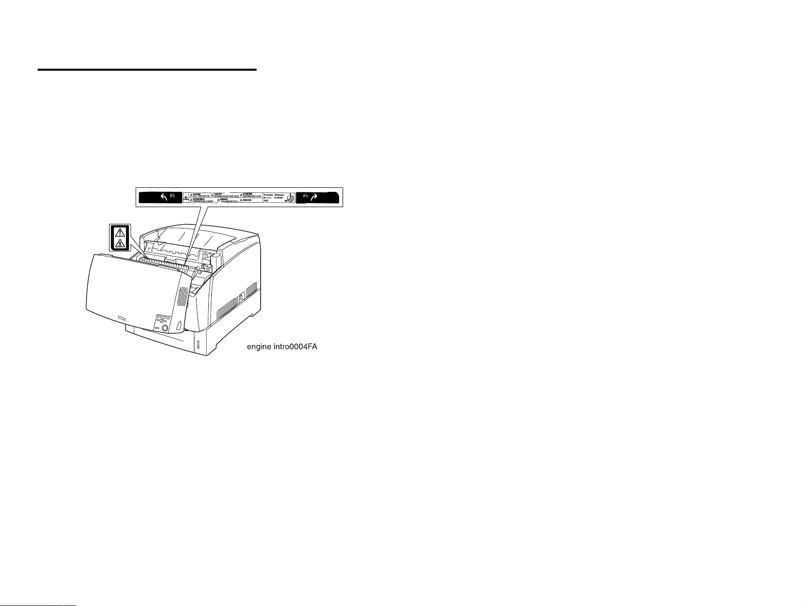
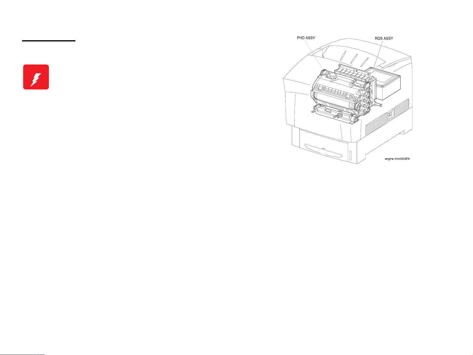
Warning and Caution Labels
Warning labels and Caution labels are placed on the printer to help
prevent accidents.
When maintaining the printer, confirm that these labels are not dirty or
peeling off.
Caution label for high temperature components
Figure 0-3. Warning and Caution Labels
Page 12
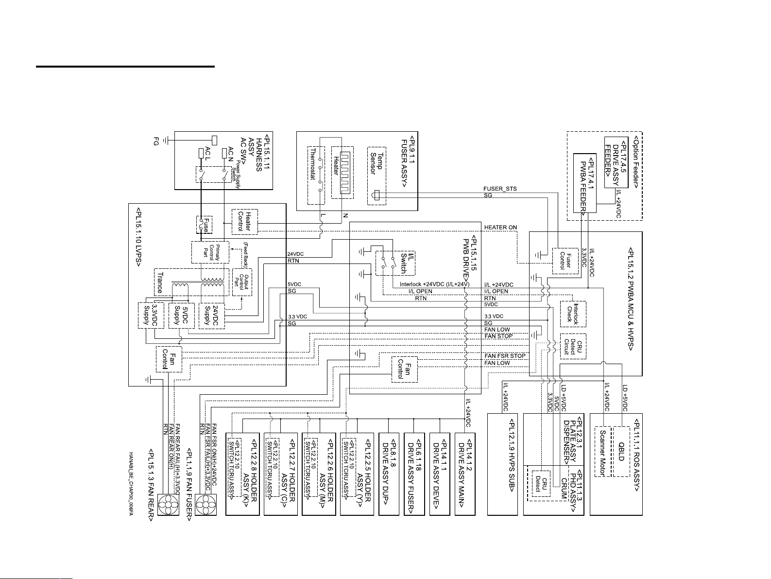
Safety System Schematic
The schematic below outlines the features of the printer's safety system.
For details about signal wires, see "Appendix - Wiring Diagram".
Page 13

Manual Contents
Chapter 1 PRODUCT DESCRIPTIONS
Chapter 2 OPERATING PRINCIPLES
Chapter 3 TROUBLESHOOTING
Chapter 4 DISASSEMBLY AND ASSEMBLY
Chapter 5 ADJUSTMENT
Chapter 6 MAINTENANCE
Chapter 7 AcuLaser C4100
Chapter 8 AcuLaser C3000
Appendix
Page 14

Revision Status
Revision Issued Date Description
A March 18, 2002 First Release
B April 19, 2002 Chapter 1
1.14.5 Panel Setting Item List “PRINTER ADJUST MENU”
• “Cleaning Cycle” and comment is added.
Chapter 3
• “Reference page number in FIP” is added.
3.3 Level 2 FIP
• “3.3.2 Self-Diagnostic Function by LCD Message” is added.
• “3.3.2.1 List of Printer Messages” is added.
• “3.3.2.2 Details of Status Message and Treatment” is added.
• “3.3.2.3 Details of Error Message and Treatment” is added.
• “3.3.2.4 Details of Warning Message and Treatment” is added.
• “3.3.3 Service Call Error Messages” is added.
• “FIP-16 NV-RAM Error” is added.
• “FIP-28 Fuser Life Over” is added.
• “FIP-48 Engine Communication Error” is added.
• “FIP-49 Verify (DIMM Slot Related) Error” is added.
• “FIP-50 Error in Standard RAM (Slot 0, 1)” is added.
• “FIP-51 ROM Checksum Error (MASK ROM for Font)” is added.
• “FIP-52 ROM Checksum Error (CODE, IPL)” is added.
• “FIP-53 ROM Module (DIMM Slot A Related) Error” is added.
• “FIP-54 EEPROM Writing Error” is added.
• “FIP-55 CCNV Hardware Error” is added.
• “FIP-56 Engine Initialization Error” is added.
• “FIP-57 SRAM (for Compression) Initialization Hardware Error” is added.
• “FIP-58 Video System Hardware Error (including PWM Calibration Error IC)” is added.
• “FIP-59 Built-in Network Hardware Error” is added.
• “FIP-60 DIMM SPD Error” is added.
Chapter 6
6.2 Maintenance Menu “Table 6-2. List of control information and control method”
• The range of count is changed.
• A comment is added.
Page 15

Revision Issued Date Description
C November 15, 2002 Preface
• A misdescription deleted.
Chapter3
• “3-1-4 Test print by engine itself” added.
D August 4, 2003 Chapter 1
1.5.1 “Reliability”
• The value of MPBF is fixed
1.10 “Consumable Components”
• The value of Transfer Unit Lifetime is revised
1.14.5 “Panel Setting Item List”
• PRINTER ADJUST MENU is revised
1.14.6.7 “Printer Adjust Menu”
• Part of text is revised
Chapter 6
6.1.2 “Consumable components and components that require regular replacement”
• The value of Transfer Unit Lifetime is revised
• The parts code of Roll Assy is fixed
Chapter 7
Additional information added for AcuLaser C4100
E August 19, 2004 [Revision up]
Chapter 8
Additional information added for AcuLaser C3000
F October 26, 2004 [Revision up]
Chapter 1:
1.5.2 "Durability" (1-19) (the description is revised)
Chapter 7:
7.1.2.1 "Product reliability" (7-482) (Error in “Durability” value is corrected)
Page 16

CONTENTS
Product Descriptions
Features......................................................................................................... 5
Specifications ............................................................................................... 7
Basic Specifications .................................................................................. 7
Various Sensors ......................................................................................... 14
Paper Specifications .................................................................................. 16
Paper Types ............................................................................................ 16
The paper that should not be used with this printer ................................ 16
Paper Source Classification .................................................................... 17
Printing Area............................................................................................ 17
Reliability and Durability............................................................................ 18
Reliability ................................................................................................. 18
Durability ................................................................................................. 19
Maintenance............................................................................................ 19
Operating Conditions (Including Comsumables).................................... 20
Storage and Transport of the Printer Main Unit (Consumables Packaged),
and Optional Products ............................................................................... 21
Electrical Feature........................................................................................ 22
Compliance with Standards and Regulations ......................................... 23
Consumable Components ......................................................................... 23
Maintenance................................................................................................ 24
Exterior View and Unit Names................................................................... 25
Controller Unit Specifications ................................................................... 27
Controller Basic Specifications................................................................ 27
Controller Configuration .......................................................................... 28
External Interface Specifications ............................................................. 28
Control Panel .............................................................................................. 33
Exterior View and Names........................................................................ 33
Display Elements Description.................................................................. 34
Button Functions Description .................................................................. 35
Special Operations.................................................................................. 36
Panel Setting Item List ............................................................................ 37
Explanation of Each Setting Menu and Setting Items ............................. 47
About RAM Expansion............................................................................... 54
Dimensions ................................................................................................. 54
Operating Principles
Print Process .............................................................................................. 56
Print Process Overview........................................................................... 56
Print Process Diagram ............................................................................ 57
Print Process Technical Explanation....................................................... 58
Flow of Print Data....................................................................................... 62
Data Flow ................................................................................................ 62
Drive Transmission Path ........................................................................... 63
DRIVE ASSY MAIN (PL14.1.2) ............................................................... 63
DRIVE ASSY DEVE (PL14.1.1) .............................................................. 64
HOLDER ASSY (PL12.2.5 ~ 8) (Y, M, C, K) ........................................... 64
DRIVE ASSY FUSER (PL6.1.18)............................................................ 65
MOTOR ASSY DUP (PL8.1.8)................................................................ 66
Paper Feed .................................................................................................. 67
Paper Feed Path (without options in use) ............................................... 67
Paper Feed Path Diagram ...................................................................... 67
Functions of Main Components................................................................ 69
Paper Cassette (PL3.1 ~ 2)..................................................................... 69
Paper Feeder (PL4.1 ~ 3) ....................................................................... 70
Housing Assy Retard (PL5.1).................................................................. 71
Chute Assy In (PL6.1) ............................................................................. 71
Chute Assy Out (PL7.1) .......................................................................... 72
Chute Assy Exit (PL8.1) .......................................................................... 73
Fuser Assy & BTR Assy (PL9.1) ............................................................. 74
Page 17

Xerographics (PL11.1) ............................................................................ 77
TCRU Assy (PL12.1 ~ 3)......................................................................... 78
Frame (PL13.1) & Drive (PL14.1)............................................................ 79
Electrical (PL15.1 ~ 2) & CONTROLLER BOARD (ESS) (PL16.1)......... 79
Switches and Sensors ............................................................................... 81
Mode ............................................................................................................ 82
Print Mode............................................................................................... 82
Operation Mode....................................................................................... 82
Control......................................................................................................... 83
Paper Size Control .................................................................................. 83
Paper Supply Selection Control .............................................................. 83
ROS Light Control ................................................................................... 83
PROCESS CONTROL ............................................................................ 84
Color Registration Control ....................................................................... 87
BTR ASSY (PL9.1.2) Control .................................................................. 88
Toner Control .......................................................................................... 89
Fuser Control........................................................................................... 90
Operating Principles for the Large Capacity Paper Unit (Option Feeder)..
91
Drive Transmission Path ........................................................................... 91
DRIVE ASSY FEEDER ........................................................................... 91
Gear Layout............................................................................................. 92
Paper Feed .................................................................................................. 93
Paper Feed Path ..................................................................................... 93
Paper Feed Path Diagram....................................................................... 93
Functions of Main Components................................................................ 94
Two Tray Module II/III (PL17.2 ~ 3) ........................................................ 94
Two Tray Module IV (PL17.4) ................................................................. 96
Switches and Sensors ............................................................................... 97
Controller Operating Principles ................................................................ 98
Troubleshooting
Overview.................................................................................................... 103
Troubleshooting Procedure ................................................................... 103
Preliminary Checks ............................................................................... 103
Precautions When Performing Work ..................................................... 104
Test print by engine itself ...................................................................... 105
Precautions When Using FIP ................................................................ 106
Level 1 FIP................................................................................................. 107
Level 1 FIP Flowchart ........................................................................... 107
Level 2 FIP................................................................................................. 108
Level 2 FIP ............................................................................................ 108
Self-Diagnostic Function by LCD Message........................................... 108
Service Call Error Messages................................................................. 118
Image Quality Troubleshooting FIP....................................................... 246
Printer Operation Troubleshooting FIP ................................................. 267
Other FIP............................................................................................... 279
Level 2 FIP –Large Capacity Paper Unit–............................................... 284
Level 2 FIP ............................................................................................ 284
Disassembly and Assembly
Overview ................................................................................................... 303
Precautions for Disassembly and Assembly ......................................... 303
Tools ..................................................................................................... 303
Items to Check after Assembly ............................................................. 303
Disassembly Assembly Procedures....................................................... 304
Large capacity paper unit removal ........................................................ 305
Removing/Replacing the Consumables ................................................ 306
Updating the Main Controller Program ROM ........................................ 306
COVER ................................................................................................. 309
CHASIS & FEEDER/CASSETTE .......................................................... 319
PAPER CASSETTE .............................................................................. 321
PAPER FEEDER .................................................................................. 323
HOUSING ASSY RETARD ................................................................... 356
CHUTE ASSY IN................................................................................... 360
CHUTE ASSY OUT............................................................................... 365
CHUTE ASSY EXIT .............................................................................. 377
FUSER ASSY & BTR ASSY ................................................................. 381
REGISTRATION ................................................................................... 383
XEROGRAPHICS ................................................................................. 387
TCRU ASSSY ....................................................................................... 389
FRAME.................................................................................................. 397
DRIVE ................................................................................................... 403
ELECTRICAL ........................................................................................ 404
CONTROLLER BOARD........................................................................ 413
Page 18

Large Capacity Paper Unit
(Option FEEDER UNIT) ........................................................................ 415
Adjustment
USB ID Input.............................................................................................. 458
Installation Procedure for Program........................................................ 458
Procedure for program operation .......................................................... 458
USB ID Confirmation ............................................................................. 460
Details of Warning Message and Treatment......................................... 498
Maintenance.............................................................................................. 499
Consumable components and regularly replaced parts........................ 499
Engine Status Sheet ............................................................................. 502
List of control information and control methods .................................... 503
Parts List for AL-C4100............................................................................ 504
Exploded Diagram.................................................................................... 508
Circuit Schematic ..................................................................................... 532
Maintenance
Maintenance.............................................................................................. 463
Preparatory Maintenance ...................................................................... 463
Consumable components and components that require regular replacement
463
Cleaning ................................................................................................ 465
Maintenance Menu ................................................................................... 466
Entry to the Maintenance Menu ............................................................ 466
Engine Status Sheet.............................................................................. 466
Clear Error Log...................................................................................... 467
Consumable components replacement ................................................. 469
Toner Cartridge replacement ................................................................ 469
Photoconductor Unit replacement ......................................................... 471
Fuser Unit replacement ......................................................................... 473
Transfer Unit replacement..................................................................... 474
Components that require regular replacement ..................................... 474
Color Registration Adjustment ............................................................... 475
AcuLaser C4100
Product Descriptions ............................................................................... 478
Features ................................................................................................ 478
Printer Basic Specification..................................................................... 479
Control Panel......................................................................................... 484
Status Sheet.......................................................................................... 495
Panel Message For Troubleshooting...................................................... 496
List of Printer Messages........................................................................ 496
Details of Error Message and Treatment .............................................. 497
AcuLaser C3000
Product Descriptions ............................................................................... 541
Features ................................................................................................ 541
Printer Basic Specification .................................................................... 543
Control Panel ........................................................................................ 544
Panel Message ..................................................................................... 549
Printer Status Information ..................................................................... 552
Main Controller ......................................................................................... 557
Major Components................................................................................ 557
Parts List for AL-C3000............................................................................ 558
Exploded Diagram.................................................................................... 561
Circuit Schematic ..................................................................................... 563
Appendix
Parts List and Explodede Diagram for Main Unit of The AcuLaser C4000
570
Attention on handling the parts list ........................................................ 570
Parts List Tables ................................................................................... 571
Exploded Diagrams............................................................................... 575
Wiring Diagrams....................................................................................... 599
P/J Locations......................................................................................... 599
Plug and Jack (P/J) Location Tables..................................................... 603
High-pressure electrode Location Tables ............................................. 607
Wiring Diagrams and Signal Information ............................................... 609
Overall Wiring Connection Diagram...................................................... 609
Wiring and Signal Descriptions between Components ......................... 611
Page 19

Notation on the Diagrams for the Wiring and Signal Descriptions between
Components.......................................................................................... 613
Parts List and Exploded Diagram for Large Capacity Paper Unit of The
AcuLaser C4000........................................................................................ 637
Attention on handling the part list .......................................................... 637
Parts List Tables.................................................................................... 638
Exploded Diagrams ............................................................................... 639
Wiring Diagrams ....................................................................................... 644
P/J Locations......................................................................................... 644
Plug and Jack (P/J) Location Tables..................................................... 645
Wiring Diagrams and Signal Information ............................................... 646
Overall Wiring Connection Diagram ...................................................... 646
Wiring and Signal Descriptions between Components ......................... 648
Notation on the Diagrams for the Wiring and Signal Descriptions between
Components.......................................................................................... 649
Component Layout................................................................................... 656
Circuit Diagrams....................................................................................... 658
Page 20

PRODUCT DESCRIPTIONS
CHAPTER
1
Page 21

EPSON AcuLaser C4000/C4100/C3000 Revision F
1.1 Features
This printer is a non-impact color page printer that takes advantage of a laser
and electrophotographic technologies. It provides 1200/600/300 dpi of
resolution and 16 ppm (A4/LT) of printing speed for both color and
monochrome printing. The main features of the printer are as follows:
ENGINE FEATURES
1. A4 tandem engine, a high-speed engine which printing speed is 16 PPM
for both color and monochrome printing (when printing A4/LT).
Engine for True 1200 dpi of high resolution and full-color printing (however
printing speed is reduced by half).
2. The Duplex Print Unit is equipped as standard. Special types of paper such
as thick paper, OHP sheets (transparency), label sealing sheets, and
envelopes cannot be printed in duplex.
3. By using high quality plain paper, higher quality printing is possible.
4. Capable of printing on thick paper and OHP sheets for laser printers.
5. Provides easy maintenance of a color laser printer. The users can replace
all consumables.
Toner cartridges (C, M, Y, K)
Photoconductor Unit
Transfer Unit
Fuser Unit
6. Standard paper feed devices are the following 2-bin; the MP Tray
(up to 100 sheets) and the Lower Cassette (up to 500 sheets, A4/LT).
By adding the two optional Lower Cassette (up to 500 sheets * 2 cassettes,
A4/LT), a maximum of 1600 sheets can be fed from the 4-bin in total.
7. Standard paper eject is up to 250 sheets into the Face-down tray.
CONTROLLER FEATURES
1. High-speed controller with a new CPU adopted
64-bit RISC CPU ---- PowerPC 750CX 400 MHz
64-bit high-speed memory ---- PC100 SDRAM DIMM
64 MB of standard RAM
By installing additional RAM, the memory can be expanded up to 576
MB (64 MB + 512 MB)
(Furthermore, by replacing the standard RAM with a 512 MB RAM, the
memory can be expanded up to 1024 MB)
2. Enhanced ASIC is equipped (VIP2, CDMC)
The color management technologies shown below have been incorporated
into the hardware to achieve high-speed processing.
CCNV3 (color conversion of RGB into CMYK)
CCMP (color compression for RGBX or CMYKX and expansion)
CLRCTL (color adjustment)
3. Three types of standard interface are available
IEEE 1284 compatible and ECP compatible parallel Interface
Ethernet interface (100 Base-TX/10 Base-T)
Universal Serial Bus (USB) 1.1
4. By expanding memory with RAM DIMMs, the following functions can be
enhanced and speeded up
CPGI drawing area
Image creating speed
Resolution
5. Firmware update function is possible (RCC compatible) when a Flash
DIMM is installed
6. HDD can be installed
Product Descriptions Features 1-5
Page 22
EPSON AcuLaser C4000/C4100/C3000 Revision F
SOFTWARE FEATURES
1. Color technologies
Smooth expanding of color images by ESC/ Page-Color
2. Reserve job function
When the printer is equipped with Option HDD, the following "Reserve Job"
can be used.
Re-print Job
Verify Job
Stored Job
Confidential Job
Registration of job information is performed by the ESC/Page-Color driver.
NOTE: Password protection is only available for "Confidential Jobs."
3. Monitoring of the printer status and printer environment by bi-directional
EJL and MIB
4. Remote panel function through a Web browser (compatible with Java
JDK1.1)
5. HDD (option)
Electronic sorting
I/F receive buffer expansion (only for Ethernet I/F)
7. Installed emulation
Standard ESC/Page-Color, PCL5e (B/W), GL-Like (B/W),
FX (B/W), ESCP2(B/W), I239X (B/W), ESC/Page
(B/W)
Options Adobe Postscript3
Others EJL, PJL mode
RCC mode (firmware update)
DIAG mode (engine adjustment)
Auxiliary software Status Sheet (description of remaining levels of
current consumables, warning occurrences, Part
Numbers)
Reserve Job List
Form Overlay List
Network Status Sheet
AUX Status Sheet (only when Type-B Level 3 is
installed)
PS3 Status Sheet (only when PostScript 3 module
is installed)
Font Sample (for each mode)
Hex dump
Support Mode
• Standby Mode setting
• Printer Adjust Menu
Maintenance Mode (Engine Status Sheet)
Font registration in the PostScript3 mode
Registration of Reserve Job and Confidential Job
Registering Form Overlay (only available for Windows environment)
6. Changing the Manual Feed specification.
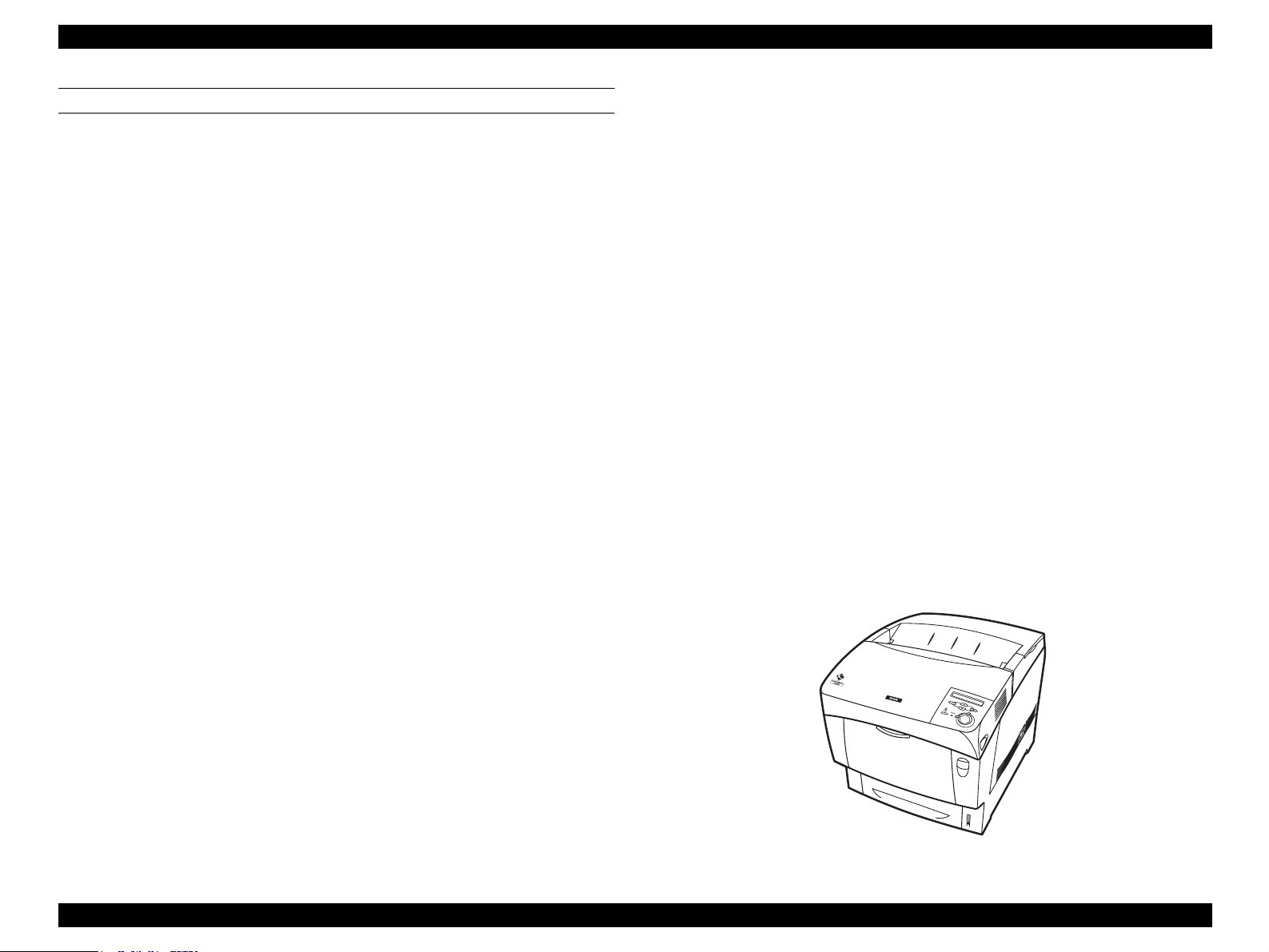
Same as EPL–5900
Figure 1-1. Exterior View of the EPSON AcuLaser C4000
Product Descriptions Features 1-6
Page 23
EPSON AcuLaser C4000/C4100/C3000 Revision F
1.2 Specifications
This section describes specifications for EPSON AcuLaser C4000.
1.2.1 Basic Specifications
1.2.1.1 Process Specifications
Printer Type Semi-conductive laser beam+Electrophotographic
with dry 2 ingredients nonmagnetic toner
Light Source 4 beam semi-conductor laser
Photoconductor Unit OPC (Organic Photoconductor) drum
Charging Roller charger
Development Exposed area development
Toner Chemical spherical toner and carrier
(in development unit)
Transfer Roller transfer method
Fixing Heated roller method and flexible belt nip method
1.2.1.2 Printer Basic Specification
METHOD
Electrophotographic method using scanning semiconductor laser beam and
dry two-component toner.
RESOLUTION
600dpi and 1,200dpi
WARMING UP TIME
30 or less seconds : when printer is powered on,
or standby mode
(22°C 55% RH environment, at rated voltage)
PRINT MODE
600dpi Mode (Normal paper): Full speed
600dpi Mode (Special paper): Low speed
1200dpi Mode: Low speed
High gross Mode: Low speed
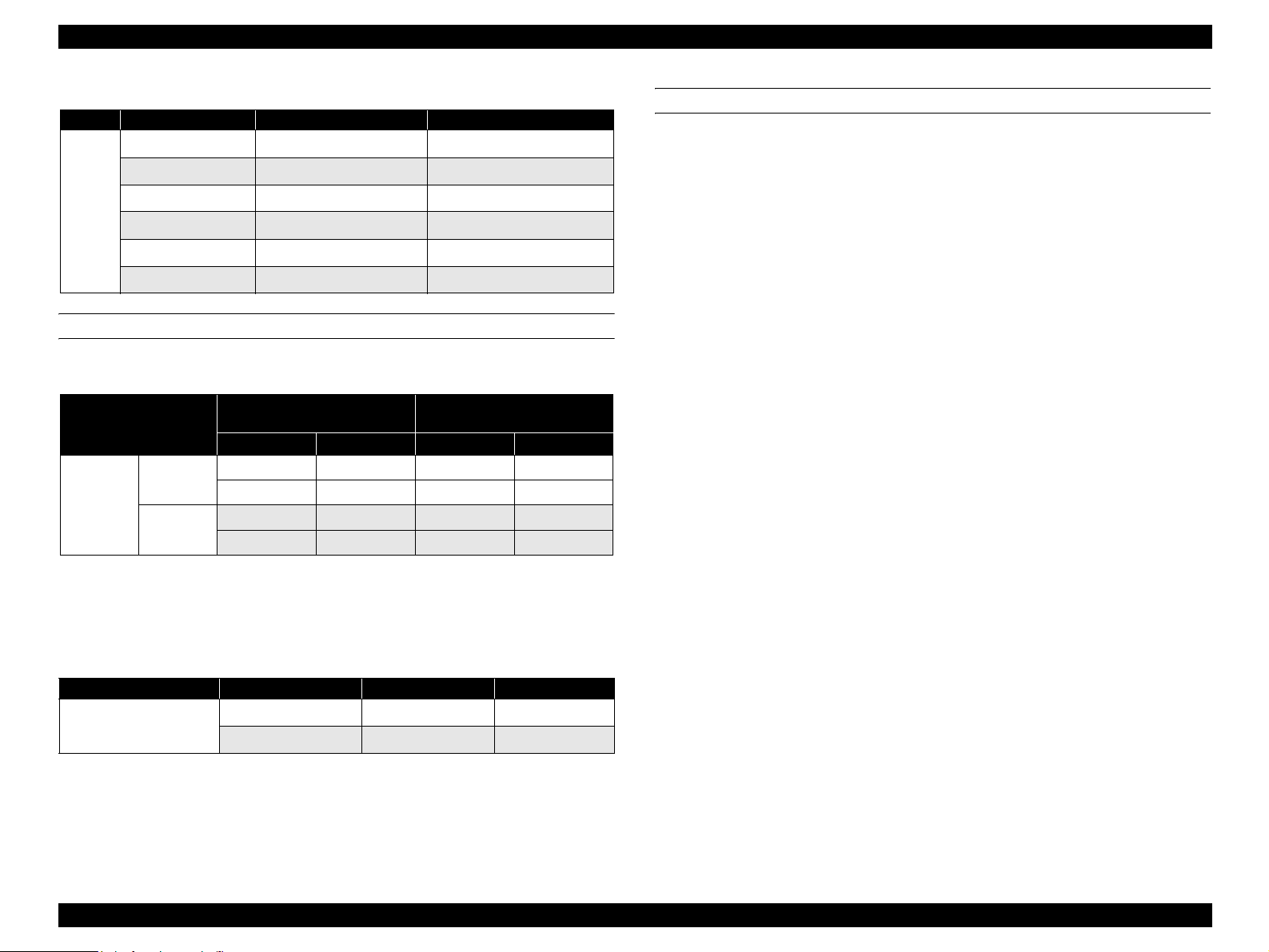
PRINTING MODE BY PAPER TYPE
Table 1-1. Printing mode by paper type
Mode <video I/F name> Paper type, thickness
Normal (low temp) <Plain paper-L mode> Plain paper: 60~75g/m2
Normal (high temp) <Plain paper-H mode> Plain paer: 65~85g/m2
Normal
paper
High quality
(low temp)
High qality
(high temp)
<Thicker paper-L mode>
<Thicker paper-H mode)
High quality paper: 76~99g/
m2
High quality paper:
85~105g/m2
Product Descriptions Specifications 1-7
Page 24
EPSON AcuLaser C4000/C4100/C3000 Revision F
Table 1-1. Printing mode by paper type
Mode <video I/F name> Paper type, thickness
Thick1 <Heavier paper-L mode> Thick paper: 100~159g/m2
Thick2 <Heavier paper-H mode> Thick paper: 160g/216m2
Special
paper
Label (low temp) <Label-L mode> Label
Label (high temp) <Label-H mode> Label
OHP <OHP mode> OHP films
Envelope <Envelope mode> Envelope
PRINTING SPEED
Simplex
A4
(SEF)
Printing
Duplex
Printing
Table 1-2. First Printing Time
Standard
MP Tray Cassette 1 Cassette 2 Cassette 3
15.0 15.5 17.0 18.5
24.0 24.5 27.5 30.5
23.0 23.5 25.0 26.5
39.0 39.5 42.5 35.5
Optional Feeder 500 Sheets
Unit
PAPER FEED REFERENCE
Centerline reference for each paper size and each paper feeder.
NOTE: Printing Speed values at full speed mode are stated upper rows of
the each column, and values at low speed mode are in lower rows
of each column.
Table 1-3. Continuous printing speed
Paper size Print mode Sinplex printing Duplex printing
A4/Letter
Full speed mode 16 10
Low speed mode 8 5
NOTE 1: Speeds shown are for plain paper L and H modes.
NOTE 2: Cleaning cycles occur during printing.
Product Descriptions Specifications 1-8
Page 25
EPSON AcuLaser C4000/C4100/C3000 Revision F
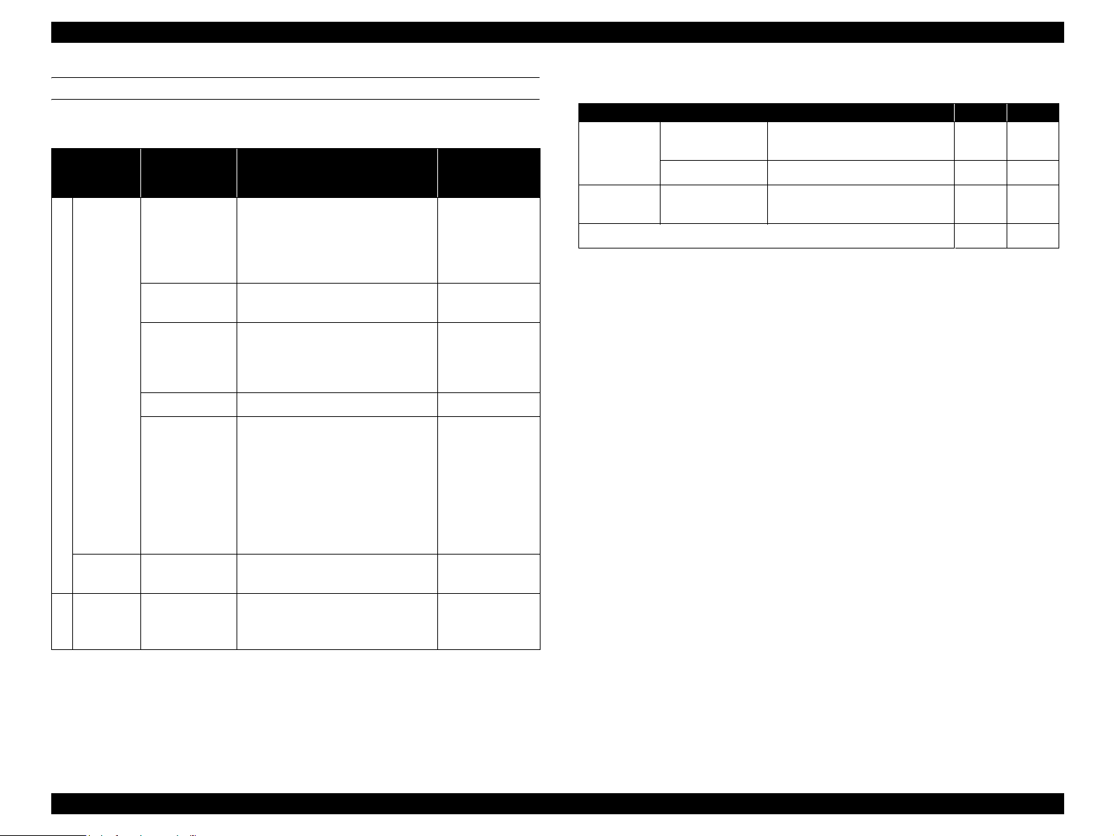
PAPER FEED
Paper
Source
MP Tray
Standard
Cassette
Table 1-4. Paper Feed
Sheets
Containing
Capacity *
1
A4, A5, B5, EXE, LT, GLG, LGL,
100 Sheets *
TBD Sheets *
(10mm)
3
GLT*
2
Unspecified sizes
Min size : 88.9 x 139.7 mm
Max size : 215.9 x 355.6 mm
1 Sheet 900mm in length
TBD Sheets A4, LT
TBD Sheets Official Postcard 190 g/m
Envelopes
(Monarch, C10, DL, C5, C6*
ISO-B5*
TBD Sheets
(10mm)
(Yokei #2, 3, 4, Youchoukei #3)*
Unspecified size
Min size :
90mm (width) × 143mm (length)
500 sheets *
(58mm)
2*3
A4, A5, B5, EXE, LT, GLG, LGL
Paper Size
5
, HLT, F4*
5
)
5
5
,
(with flap opened)
Paper Type *
Standard Paper
Normal Paper
Standard Paper
Normal Paper
Special
Applications
(Labels,
Transparencies)
5
---
Standard Paper
Normal Paper
Applicable
2
Table 1-5. Optional Paper Source Combination
Combination (1) (2)
Standard
−
4
Optional
First Cassette Cassette 1 (500 Sheets)
Second and
Third Cassette
500 Sheets x 2 Cassette Unit
Total Sheets 600 1,600
2
*1: RX-80 (80g/m
)
MP Tray
(100 sheets*
1
)
−
500
Sheets
Unit
Optional
500 sheets *
(58mm)
2*3
A4, A5, B5, EXE, LT, GLG, LGL
Standard Paper
Normal Paper
*1: The values in ( ) is capable containing height
*2: Standard Paper : at FX P Paper (64g/
*3: Standard Paper : at Fuji XEROX 4024 DP 20lb (75 g/
2
m
)
2
m
)
*4: Refer to 1.4 "Paper Specifications"
*5: Paper size supported by the firmware (unsupported by the video I/F)
Product Descriptions Specifications 1-9
Page 26
EPSON AcuLaser C4000/C4100/C3000 Revision F
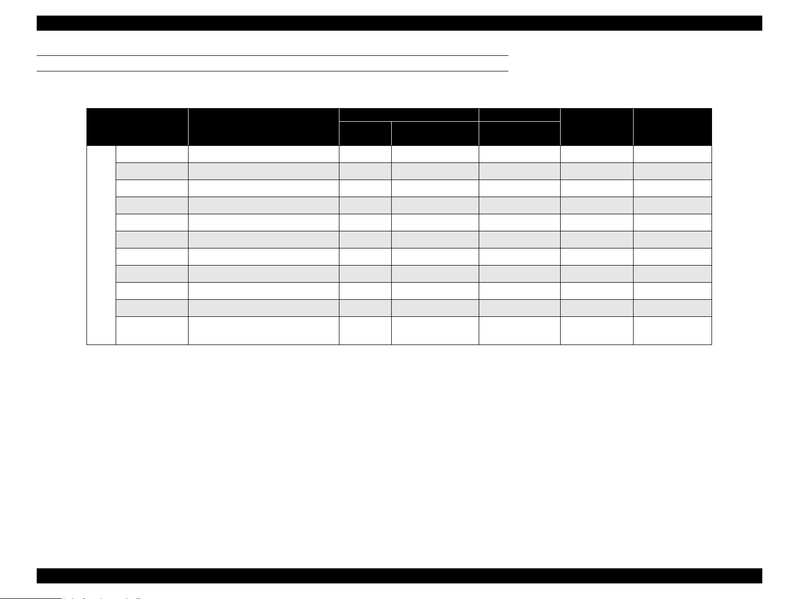
APPLICABLE PAPER SIZES, PAPER TYPES, AND PAPER ORIENTATION
Table 1-6. Applicable Paper Sizes, Paper Types, and Paper Orientation 1
Paper Size
Dimensions in mm
(inches)
MP Tray
A4 210.00 x 297.00
6
A5*
148.00 x 210.00 SEF
B5 182.00 x 257.00 SEF
LT 215.90 x 279.40 (8.50 x 11.00”)
Standard Optional
cassette
(500 Sheets)
500 Sheets
2
Unit *
Duplex Printing
3
*
SEF
SEF
Paper
Orientation
HLT 139.70 x 215.90 (5.50 x 8.50”)
−−− −−− −−− SEF
GLG 215.90 x 330.00 (8.50 x 13.00”) SEF
LGL 215.90 x 335.60 (8.50 x 14.00”)
Normal Paper
EXE 184.15 x 266.70 (7.25 x 10.50”) SEF
5
GLT*
5
F4*
Uncut Paper *
203.20 x 266.70 (8.00 x 10.50”)
210.00 x 330.00 −−− −−− −−− SEF
Width: 88.90 ~ 215.90
1
Length: 139.70 ~ 900.00
−−− −−−
−−−SEF
SEF
−−−
*1: Paper of more than 355.60mm (14 inches) in length must be fed manually.
*2: Supported envelope sizes differ by destinations.
*3: Refer to "Envelope Orientation" for details on feeding direction of envelopes.
*4: Flatten the curling paper.
*5: Paper size supported by the firmware (unsupported by the video I/F)
*6: When installing the A5 paper to cassette, set exclusive adapter in cassette.
• LEF (Long Edge Feed) : the long edge of the paper is fed to the printer.
• SEF (Short Edge Feed) : the short edge of the paper is fed to the printer.
• ---: Unsupported
SEF
Product Descriptions Specifications 1-10
Page 27
EPSON AcuLaser C4000/C4100/C3000 Revision F
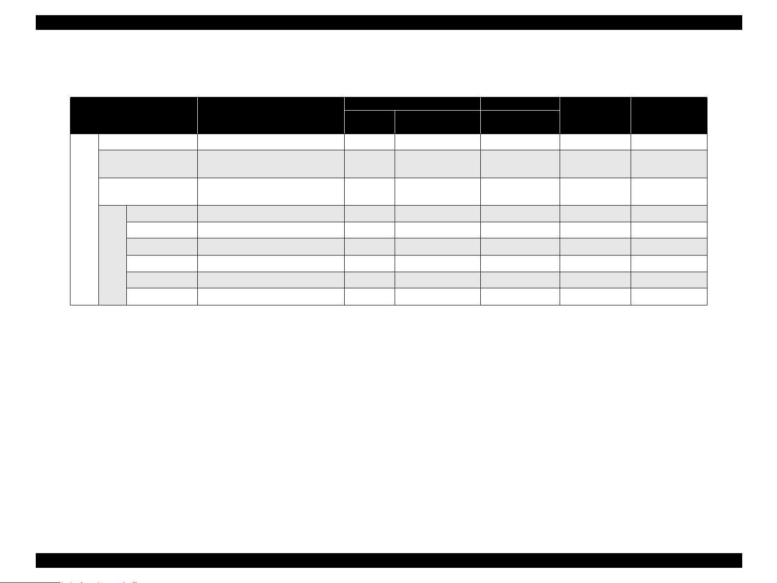
Special Applications : See Table 1-7
Table 1-7. Applicable Paper Sizes, Paper Types, and Paper Orientation 2
Standard Optional
cassette
(500 Sheets)
−−− −−−
500 Sheets
2
Unit *
Duplex Printing
3
*
−−−
Paper
Orientation
SEF
−−− −−− −−− SEF
Paper Size
Official Postcard *
Transparency
Dimensions in mm
(inches)
4
100.00 x 148.00
A4:210 x 297,
LT:215.9 x 279.4
Paper
Tray
Labels
A4:210 x 297,
LT:215.9 x 279.4
Monarch 98.43 x 190.50 (3 7/8” x 7 1/2”)
4
*
Com-10 104.78 x 241.30 (4 1/8” x 9 1/2”) −−− −−− −−− SEF*
3
*
2
DL 110.00 x 220.00 −−− −−− −−− SEF*
Special Applications
C5 162.00 x 229.00
5
C6*
Envelopes *
ISO-B5*
5
114.00 x 162.00 −−− −−− −−− SEF*
176.00 x 250.00 −−− −−− −−− SEF*
*1: Paper of more than 355.60mm (14 inches) in length must be fed manually.
*2: Supported envelope sizes differ by destinations.
*3: Refer to Section "Envelope Orientation" for details on feeding direction of envelopes.
*4: Flatten the curling paper.
*5: Paper size supported by the firmware (unsupported by the video I/F)
*6: When installing the A5 paper to cassette, set exclusive adapter in cassette.
• LEF (Long Edge Feed) : the long edge of the paper is fed to the printer.
• SEF (Short Edge Feed) : the short edge of the paper is fed to the printer.
• ---: Unsupported
−−− −−− −−− SEF
−−− −−−
−−− −−−
−−− SEF*
−−−
SEF*
3
3
3
3
3
3
Product Descriptions Specifications 1-11
Page 28
EPSON AcuLaser C4000/C4100/C3000 Revision F
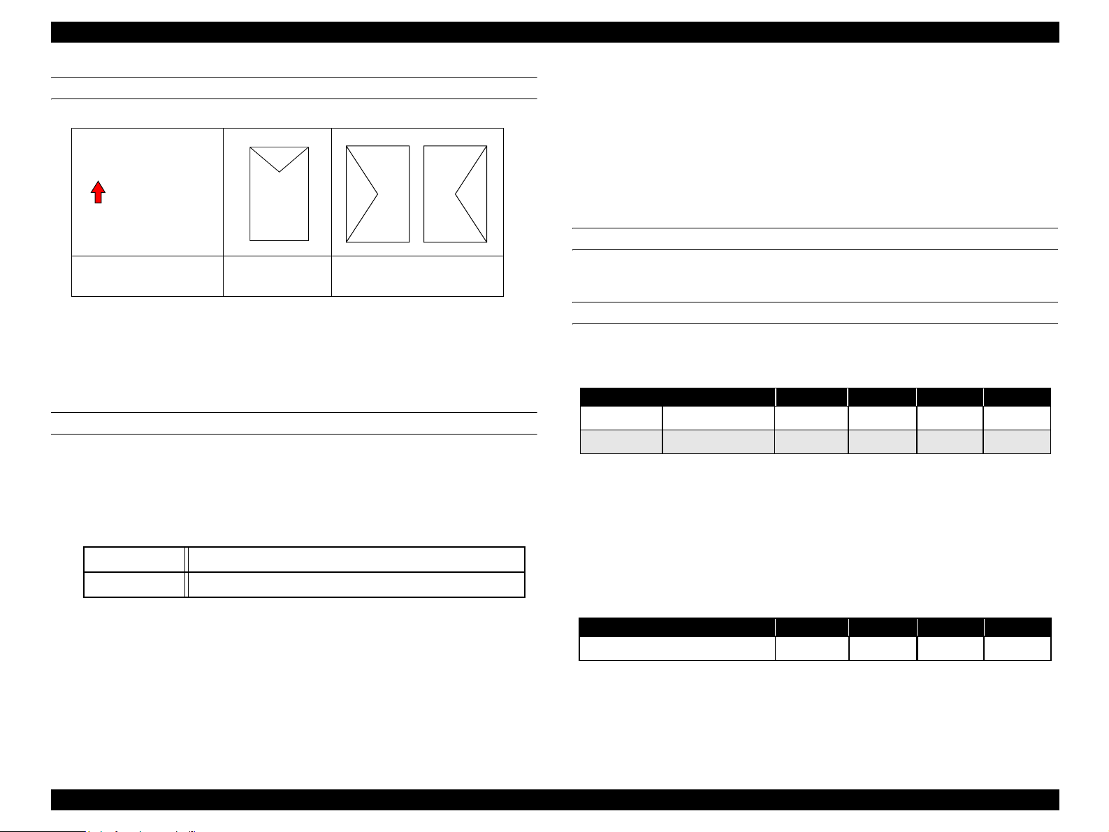
ENVELOPE ORIENTATION
Feeding Direction
Envelope Type C5, ISO-B5
Com-10, DL, C6
Monarch
NOTE 1: Only envelopes without adhesive or adhesive tapes can be used.
NOTE 2: Envelopes have to be set with flap opened, and should be fed by LEF
if width dimension is longer than length dimension.
NOTE 3: A printing side is set to the bottom.
PAPER FEED SIZES
Main Unit
MP Tray
Paper size: Regular paper sizes or unspecified paper sizes within
following useable paper size.
Duplex Unit
Paper size: The regular size and unspecified size described in the
Table 1-6 and 1-7 can be fed.
Paper thikneess: 64 ~ 105g/m
2
500 sheets x 2 unit (Large capacity paper unit)
Same specification as cassette of the main unit
OUTPUT PAPER CAPACITY
Maximum of 250 sheets to face-down tray (at 22°C, 55%RH, standard paper).
DIMENSIONS
Stand Alone Outline Dimensions and Weights
Table 1-8. Stand Alone Outline Dimensions and Weights
Width Depth Height Weight
Standard Main Unit only 439 638 445 29.8
Optional 500 Sheets Unit 439 563 336 19.0
Unit: mm, kg
NOTE 1: Unpacked dimensions are stated.
NOTE 2: Dimensions has ±1%mm difference, weights are ±1%kg difference.
NOTE 3: Main unit weights do not including consumable items
Minimum Width 88.9mm x to Length 139.7mm
Maximum Width 215.9mm x to Length 355.6mm to 900.0mm
Paper thikneess: 60 ~ 216g/m
900.0mm are 64 ~ 105g/m
2
(Uncut paper for length 355.6mm to
2
)
Outline Dimensions and Weights with Options Installed
Table 1-9. Outline Dimensions and Weights with Options Installed
Width Depth Height Weight
Main Unit and 500 Sheets Unit 439 638 781 48.8
Cassette
Paper size: Only the regular size described in the Table 1-6 and 1-7
can be fed.
Paper thikneess: 60 ~ 105g/m
2
NOTE 1: Unpacked dimensions are stated.
NOTE 2: Dimensions has ±1%mm difference, weights are ±1%kg difference.
NOTE 3: Main unit weights do not including consumable items.
Unit: mm, kg
Product Descriptions Specifications 1-12
Page 29
EPSON AcuLaser C4000/C4100/C3000 Revision F
CONSUMABLE COMPONENTS
Toner Cartridge: Black (K), Cyan (C), Magenta (M), Yellow (Y)
Photoconductor Unit
Transfer Unit
Fuser Unit
* Refer to Consumable Components on Page 23.
NOTE: Refer to Ch6 about handling the consumable components.
COMPONENTS THAT REQUIRE REGULAR REPLACEMENT
The life of regular replacement parts which are not replaced by the user.
Pickup Roller 100K pages
NOTE: Refer to Ch6 about handling the components require regular
replacement.
POWER SUPPLY
115V / 120V ± 10% 50 to 60Hz ± 3Hz
220V / 240V ± 10% 50 to 60Hz ± 3Hz
Supply to controller: 3.3V/5.0A
5.0V/1.0A
POWER CONSUMPTION
120V 240V
Maximum current rated TBD TBD
PRODUCT LIFETIME
Main unit
300K printed pages or 5 years, whichever comes first.
(with periodic part replacement. See Components that require regular
replacement on Page 13)
NOISE
Table 1-10. Noise
Main Unit With Options Installed
MP Tray Cassette MP Tray Cassette
During printing Full
Speed Mode
During Printing Low
Speed Mode
During standby 35 dB (A)
Saving Electricity Mode Back Ground Noise
54.0 dB (A) 52.0dB (A) 54.0dB (A) 54.0dB (A)
54.0 dB (A) 55.0 dB (A) 55.0 dB (A) 55.0 dB (A)
NOTE 1: Values measured by ISO7779 9-point method.
NOTE 2: Measured with MP tray closed.
NOTE 3: Simplex and duplex printing are the same values.
EMISSION
Ozone Concentration: 0.01ppm or less (New Blue Angel standard compliance).
Dust Concentration: 0.1mg/m
3
Maximum at continuous printing 850W 850W
Average at continuous printing 450Wh 450Wh
Average during standby with heating on 850Wh 850Wh
Power
Average during power save mode with
consumption
heating off
45Wh or less 45Wh or less
HAZARDOUS MATERIALS
None of the OPC, toner or plastic contains hazardous materials.
Product Descriptions Specifications 1-13
Page 30
EPSON AcuLaser C4000/C4100/C3000 Revision F
1.3 Various Sensors
Table 1-11. Various Sensors
Unit Detectable Matter Detectable Device Remarks
Cartridge mounted/unmounted Automatic detection (switch method)
1
Toner Cartridge
(Cyan, Magenta, Yellow, Black)
New cartridge Automatic detection*
Cartridge type --- Refer to *9
Near life end Sensor detection
Work life end Softcounter
Cartridge mounted/unmounted Automatic detection (By IC chip)
Photoconductor Unit
Transfer Unit
Fuser Unit
Standard Paper Feeder
Optional
Paper Feeder
MP Tray
Cassette
500 Sheets x 2 cassette unit
Near life end Softcounter Refer to *2
Work life end Softcounter Refer to *2
Cartridge mounted/unmounted Automatic detection
Near life end Sensor detection Refer to *2
Work life end Softcounter Refer to *2
Cartridge mounted/unmounted Automatic detection
Near life end Softcounter Refer to *2
Work life end Softcounter Refer to *2
Paper size Automatic detection
Out of Paper Automatic detection by Photo Sensor and Mechanical Lever
Cassette mounted/unmounted Automatic detection by Mycro Switch
Paper size Automatic detection by Paper Regulation Board
Paper near end*
Out of paper Automatic detection by Photo Sensor and Mechanical Lever
Cassette mounted/unmounted
Paper size
Paper near end
Out of Paper
2
Automatic detection by Photo Sensor and Mechanical Lever
Identical to standard cassette
Detects 50 ± 20sheets
(FX-P paper 64g/m
2
)
Product Descriptions Various Sensors 1-14
Page 31

EPSON AcuLaser C4000/C4100/C3000 Revision F
*1: A used cartridge (with toner remaining) will be detected as a new cartridge if installed after Near End has been detected. Replacement of a toner cartridge before
Near End has been detected will result in erroneous detection of Near End and End.
*2: The following table describes detection consumables life end.
Name Detection Near end End Engine stop*
Toner Cartridge*
4
Photoconductor Unit*
Transfer Unit*
Fuser Unit*
6
8
*3: If the Engine Stop function activates, be sure to allow the engine to stop. Continued operation could damage the printer.
*4: Near End and End activation times can be adjusted by the Controller.
*5: Differs according to usage conditions.
*6: Near End, End and Engine Stop will activate when either the page count or the Dispense Time for any color is reached. Near End and End activation times can
be adjusted by the Controller.
*7: End and Engine Stop will activate when either the page count or the Dispense Time for any color is reached.
*8: After replacement, resetting the item in the control panel will detect the new part.
*9: The shape of cartridge housing is unique to each color, and this prevents it from installing on the wrong cartridge holder.
Sensor detection + Dispense Time ON Sensor ON + 75 Sensor ON + 86
Black (3,350) (3,425) (3,436)
(Near End, End and Engine
Yellow (2,975) (3,050) (3,061)
Stop sensor Dispense Time
for reference only) *5
Magenta (2,975) (3,050) (3,061)
Cyan (2,975) (3,050) (3,061)
Printing page count 24k 30k 45k
Black 39,040 48,800 73,200
5
Yellow 32,800 41,000 61,500
Dispense Time
Magenta 32,800 41,000 61,500
Cyan 32,800 41,000 61,500
Detection sensor
Printing page count
ON
Sensor ON + 500 Sensor ON + 600
Dispense Time Sensor ON + 1,875 Sensor ON + 2,250
(Printing page count: reference only) (17.5k) (18.0k) (18.1k)
Printing page count 80k 100k ---
3
NOTE: Dispense Time is a controller count value. Units are seconds.
Product Descriptions Various Sensors 1-15
Page 32

EPSON AcuLaser C4000/C4100/C3000 Revision F
1.4 Paper Specifications
1.4.1 Paper Types
Standard Paper
FX P Paper (64g/m
XEROX 4024 DP 20lb (75g/m
Normal Paper
2
60g/m
generally applied copy paper, recycled paper
to 105g/m
Special Applications
Labels
Transparencies
Thick paper (105 to 216g/m
NOTE 1: lb : Ream weight = lb / 500 sheets / 17”×22” (431.8X558.8mm)
2
g/m
: 1 g/m2= 0.2659763 lb
1.4.2 The paper that should not be used with this printer
The following types of paper should not be used with this printer.
They could cause printing defects, paper jams or printer malfunctions.
2
) : A4
2
) : LT
2
(16 lb to 28lb)
2
)
Paper with punch holes or perforations.
Creased, curled or torn paper.
Irregularly shaped paper or paper with non-perpendicular corners.
Labels that peel off easily.
Paper with glue, staples or paper clips attached to it.
Ink jet paper for special applications (super-fine, glossy, glossy
film, etc.).
Sheets already printed on other color/monochrome laser printers
or photocopiers.
OHP transparency sheets for color copiers or color laser printers.
Iron applied cloth transfer materials (for ink jets, laser printers).
Postcards of any type for ink jets.
Sheets of paper stuck together.
Sheets deteriorate or discolor by heat of the Fuser Unit (about
TBD °C or less).
When non-official postcards with illustrations are used, paper feed
roller may be soiled with paper dust, and these postcards are not
fed properly. In this case cleaning is required following the 1.11
"Maintenance"
Copy paper (Carbon paper, non-carbon paper), thermal paper,
impact paper, acid-based paper.
Paper that was previously used in a thermal or ink jet printer.
Paper that is too thin or too thick.
Paper that is wet or damp.
Paper with special coatings or colored printer paper with
processed surfaces.
Glossy (too slick on its surface) paper, or paper with too smooth /
rough surfaces.
Paper with significantly different roughness on each surface.
Product Descriptions Paper Specifications 1-16
Page 33

EPSON AcuLaser C4000/C4100/C3000 Revision F
1.4.3 Paper Source Classification
Table 1-12. Paper Usability for Each Paper Source
Special Applications
Standard
Paper
MP tray
Standard
Optional
Cassette
Duplex
500 Sheet
Unit
A: Paper feed reliability and image quality assured.
B: Paper feed reliability and image quality assured, but only for the use
of generally applied types of paper.
C: Paper feed and Printing are possible for only generally applied types
of paper.
D: Sheets cannot be fed.
Normal
paper
Transparencies
ABCCCCC
A B D D D D D
ABDDDDD
A B D D D D D
Official
Postcard
1.4.4 Printing Area
PRINTABLE AREA
210.9 x 351.6
210.9 x 896.0 (at the time of setting uncut paper)
Labels
Thick paper
Envelope
GUARANTEED PRINTING AREA
Area with a margin of 4 mm from each side. Refer to the following
figure. (Uncut paper is not applicable.)
4 mm
4 mm
Guaranteed
Printing
Area
4 mm
4 mm
Figure 1-2. Guaranteed Print Area
Product Descriptions Paper Specifications 1-17
Page 34
EPSON AcuLaser C4000/C4100/C3000 Revision F
1.5 Reliability and Durability
1.5.1 Reliability
MPBF
100K pages
NOTE: Average number of pages printed until the occurrence of a
malfunction which either cannot be solved by the user or requires
the replacement of a part.
PAPER FEED RELIABILITY
Paper Jam Rate
Table 1-13. Paper Jam Rate
Standard MP Tray
Paper Type
Standard Paper 1/1,300 1/1,800 1/5,000 1/3,000
Normal Paper 1/2,000 1/1,200 1/3,000 1/1,800
Labels 1/100 −− −
Special
Applications
Official
Postcards
Transparencies 1/100 −− −
Thick Paper 1/100 − 1/100 −
Simplex
Printing
1/100 − − −
Duplex
Printing
Standard Cassette and
Optional 500 Sheets Unit
Simplex
Printing
Duplex
Printing
Multiple-Sheet Feed Rate
Table 1-14. Multiple-Sheet Feed Rate
Paper Type Standard MP Tray
Standard Paper 1/1,500 1/2,500
Normal Paper 1/1,000 1/1,500
Special Applications 1/50 1/50
NOTE 1: Based on the use of paper taken from a newly opened package.
NOTE 2: Does not include multiple-sheet feed at the boundary.
* Boundary means sheets boundary between original paper and
replenished paper, occurring after paper is replenished.
Standard Cassette and
Optional 500 Sheets Unit
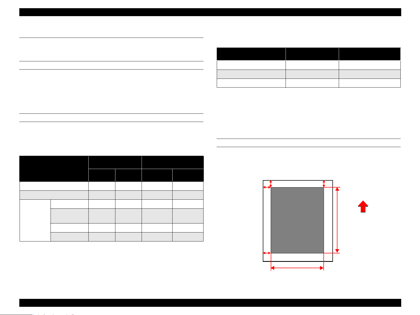
PRINTING START POSITION ACCURACY
(With standard paper fed from MP tray or paper cassette)
Reference point of main scanning direction (c) ±2.5mm
Reference point of sub-scanning direction (a) ±2.0mm
.
a
c
Printing Area
b
Paper Feed
f
Direction
NOTE 1: Based on the use of paper taken from a newly opened package.
d
NOTE 2: Includes miss feeds, multiple-sheet feed, and other kind of jams.
Does not include multiple-sheet feed at the boundary.
e
Figure 1-3. Print Position Accuracy
Product Descriptions Reliability and Durability 1-18
Page 35

EPSON AcuLaser C4000/C4100/C3000 Revision F
SKEW
(With standard paper fed from MP tray or Paper cassette)
Table 1-15. Paper Skew
Printing Page Scanning Direction A4
Main Scanning Direction |a - b| 1.23
Simplex
Sub Scanning Direction |c - d| 1.78
Main Scanning Direction |a - b|
Duplex
Sub Scanning Direction |c - d|
Table 1-16. Measured by Dot 2 pattern
A4
Between a to b 195.58mm
Between c to d 282.61mm
HEIGHT OF CURL OF PRINTED PAGES
± 15mm or less (at the standard paper)
1.5.2 Durability
PRINTING VOLUME
Maximum 30K pages
Average 5K pages / month
1.5.3 Maintenance
MTTR
Averages within 30 minutes. 95% is complete within 50 minutes. Time for
examining malfunction is not included.
(time required for service personnel to determine and correct the cause of the
malfunction)
Product Descriptions Reliability and Durability 1-19
Page 36

EPSON AcuLaser C4000/C4100/C3000 Revision F
1.6 Operating Conditions
(Including Comsumables)
AIR TEMPERATURE AND HUMIDITY
Table 1-17. Air Temperature and Humidity
Temperature (°C) Humidity (%RH) Others
Printer is under operation
Printer is stopped - 20 to 40 5 to 85
AIR PRESSURE
Altitudes : 0 to 3,100m
LEVEL
Front and Back : ± 5 degrees
Left and Right : ± 5 degrees
LIGHTING
5 to 32 15 to 85
With no
condensation
SPACE REQUIREMENTS
In order to ensure that the printer operates properly, provide at least as
much space as shown in the diagram below.
To open the cover and be able to replace the consumables easily, provide
at least 350 mm of space above the top of the printer.
3,000 lx or less (no exposure to direct sunlight)
Figure 1-4. Space Requirement
Product Descriptions Operating Conditions (Including Comsumables) 1-20
Page 37

EPSON AcuLaser C4000/C4100/C3000 Revision F
1.7 Storage and Transport of the Printer Main Unit
(Consumables Packaged), and Optional
Products
TEMPERATURE AND HUMIDITY CONDITIONS
Main unit (Consumables packaged)
Table 1-18. Temperature and Humidity
Temperature
(°C)
Normal
Conditions
Severe
Conditions
0 to 35 15 to 80 12 months
High
temperature :
35 to 40
Low
temperature :
-20 to 0
500 sheets x 2 cassette unit (Oprion)
Humidity
(%RH)
High
humidity :
80 to 95
Low
humidity :
5 to 15
Warranty
Period
Maximum
of 48 hours
Altitude (m) Others
No
0 to 3,100
condensation
allowed
TRANSPORT BAROMETRIC PRESSURE
70.9275 kPa Minimum (15,000m) *
*: In pressurized luggage compartment
DROPPING
Table 1-20. Dropping
Dropping Height (cm) Dropping Direction
Main Unit 46
Optional 500 Sheets Unit 76
1 corner, 3 edges,
6 sides, one time each
VIBRATION
Frequency : 5 to 100Hz, 100 to 5Hz
Acceleration : 6.86m/s
2
(0.7 G)
Direction of application : 3 dimensional
Time of application : 50 minutes along each X, Y, Z axis, total of 150
minutes
Table 1-19. Temperature and Humidity
Normal
Conditions
Severe
Conditions
Temperature
(°C)
-20 to 50 5 to 85 12 months
High
temperature :
50 to 60
Humidity
(%RH)
High
humidity :
85 to 95
Warranty
Period
Maximum
of 48 hours
Altitude (m) Others
No
0 to 3,100
condensation
allowed
Product Descriptions Storage and Transport of the Printer Main Unit (Consumables Packaged), and Optional Products 1-21
Page 38
EPSON AcuLaser C4000/C4100/C3000 Revision F
1.8 Electrical Feature
Specifications here are not applicable to any optional units.
FAST TRANSIENT / BURST (AC LINE NOISE)
EN61000-4 (IEC1000-4-4 ; 1995) compliance
Voltage 1kv : no malfunction occurs such as defective image quality.
2kv : no damage allowed.
INSTANTANEOUS OUTAGES
DIP 95% (at -10% of rated current) 0.5 cycle
No effect on printing quality
RESISTANCE TO STATIC ELECTRICITY
EN61000-2 (IEC1000-4-2 ; 1995) compliance
No malfunction such as defective image quality or no errors allowed even
if ± 4kv of static electricity noise is in contact discharge.
DIELECTRIC STRENGTH
No break down during application of the voltages shown below for a one
minute period.
Table 1-21. Dielectric Strength
Across primary and chassis
of power supply transformer
For 200V system models AC 3,000V AC 1,500V
(Across primary
and chassisi)
LEAK CURRENT
Table 1-22. Leak Current
Destination Leak Current
Taiwan (110 V) 3.5 mA or less
China (230 V) 3.5 mA or less
INRUSH CURRENT
0.5 cycle 100 A or less (The time of heater inrush is included.)
INSULATION RESISTANCE
10MΩ or more
Product Descriptions Electrical Feature 1-22
Page 39

EPSON AcuLaser C4000/C4100/C3000 Revision F
1.9 Compliance with Standards and Regulations
SAFETY STANDARDS
For 200V system models:
IEC 60950 2
SAFETY STANDARDS (LASER TRANSMISSION)
IEC825
FDA
EMI
For 120V system models (US models) : FCC class B
For 200V system models : EN55022
ELECTRICAL POWER HIGH FREQUENCY
None
ELECTRICAL POWER CONSUMPTION
Conforms to International Energy Star Program standard
60 minutes / 45W or less
nd
Edition / EN60950 / A1 - A4 / CE Mark
1.10 Consumable Components
SPECIFICATIONS
Table 1-23. Specifications
Name Lifetime Dimensions (mm) Weight (kg)
Toner Cartridge
(Black)
Toner Cartridge
(Cyan)
Toner Cartridge
(Magenta)
Toner Cartridge
(Yellow)
Photoconductor
Unit
Transfer Unit 25K sheets W:309, D : 85, H : 60 0.5
Average of 8,500
printed sheets*
Average of 6,000
printed sheets*
30 to 50K sheets*
1
1
2
W:339, D : 146, H : 179 4.5
*1: The number of sheets is the approximate number of printable images using
A4 landscape continuous printing at 5% image occupation rate.
The first cartridge will Near End for TBD page count. (In order to fill the
developer with toner.)
*2: Work life will differ with usage conditions.
W :340
D : 51
H : 55
W :329
D : 51
H : 53
0.32
0.295
0.285
OTHERS
Toner : No materials hazardous to human health
(conform to OSHA, TSCA, EINECS)
OPC : No materials hazardous to human health
(OSHA compliance)
Ozone generation : Conform to UL 478, 5th printing
Materials : Swiss Environmental Protection Standards
compliance (contains no Cds)
Product Descriptions Compliance with Standards and Regulations 1-23
Page 40

EPSON AcuLaser C4000/C4100/C3000 Revision F
PACKING STORAGE AND TRANSPORT ENVIRONMENTS
Temperature and Humidity Conditions
Table 1-24. Temperature/Humidity
Conditions Temperature Humidity Warranty Period
Normal 0 to 35
High temp. 35 to 45
Severe
Low temp. -20 to 0
°C 15 to 80% 24 months
°C 80 to 95%
°C 5 to 15%
Maximum of one
month
TRANSPORT BAROMETRIC PRESSURE
70.9275 kPa Minimum (15,000m) *
*: In pressurized luggage compartment
DROPPING
Table 1-25. Dropping
Dropping Height (cm) Dropping Direction
Consumables 91.0 1 corner, 3 edges, 6 sides
1.11 Maintenance
Table 1-26. Maintenance
Maintenance Item Period Maintenance Method
Pickup roller
(Roll Assy)
At the time of paper feed
performance degradation
Wipe with a dry cloth.
VIBRATION
Frequency : 5 to 100Hz, 100 to 5Hz
Acceleration : 6.86m/s
2
(0.7 G)
Direction of application : 3 dimensional
Time of application : 50 minutes along each X, Y, Z axis, total of 150
minutes
Product Descriptions Maintenance 1-24
Page 41

EPSON AcuLaser C4000/C4100/C3000 Revision F
1.12 Exterior View and Unit Names
The table below lists the major exterior parts names. For the corresponding
location, see the following figures. Note if any part names differ from the
descriptions in the User’s Guide, they are shown in the brackets.
Table 1-27. Exterior View and Unit Parts
No. Part name
1 Control panel
2 Top cover
3 Output tray
4 Power switch
5 Latch on cover A
6 Latch on cover B
7 Standard lower cassette
8 MP tray (Multi-Purpose tray)
9 Expansion tray
10 Large capacity paper unit (option)
Figure 1-5. Exterior view and Unit parts 1
11 AC inlet
12 Stopper
13 Interface card slot cover
14 Ethernet interface connector
15 Parallel interface connector
16 USB interface connector
17 Transfer unit
18 Fuser unit
19 Photoconductor unit
20 Toner cartridge
21 Cover D (cover assy top PHD)
Product Descriptions Exterior View and Unit Names 1-25
Page 42

EPSON AcuLaser C4000/C4100/C3000 Revision F
Figure 1-6. Exterior view and Unit parts 2
Figure 1-7. Exterior view and Unit parts 3
Product Descriptions Exterior View and Unit Names 1-26
Page 43

EPSON AcuLaser C4000/C4100/C3000 Revision F
1.13 Controller Unit Specifications
1.13.1 Controller Basic Specifications
CPU
CPU : 64-bit RISC PowerPC 750CX 400 MHz
ASIC : VIP2
CDMC (color conversion, color compression,
color adjustment)
RAM
SDRAM : 64-bit width DIMM (168 pins, 3.3V, PC100)
2 slots (the standard RAM must be installed to
slot-1 and SDRAM DIMM must be installed to
slot-0)
Standard : 64 MB
Optional RAM : 32 MB, 64 MB, 128 MB, 256 MB, 512 MB
A maximum of 1024 MB for both two slots by
installing 512MB
NOTE: The standard 64 MB RAM must be removed
HOST INTERFACE
Standard Parallel 1ch Bi-directional compatible with IEEE 1284
standard, B-type connector
Compatibility, Nibble, ECP
Ethernet 100 Base-TX/10 Base-T
USB 1.1
Option :Type-B1 slot (Level 3 compatible)
PRINTER SETTINGS
Printer Settings : Panel settings, EJL, PJL, HTTP, SNMP and
ENPC
Storage cell : EEPROM 32 Kbytes
CONTROL PANEL
20-digit LCD, 3 LEDs, 6 buttons
HDD
1 (optional) IDE type
ROM
32 - bit width
INSTALLATION METHOD
The slide drip method that inserts from the back of the main unit
Program : 4 MB (Flash ROM DIMM)
Fonts : 4 MB
Expansion ROM : 1 slot (ROM DIMM slot) (can be installed and
removed only when turning off the printer)
A slot : PS3, font ROM module
Product Descriptions Controller Unit Specifications 1-27
Page 44

EPSON AcuLaser C4000/C4100/C3000 Revision F
1.13.2 Controller Configuration
This printer can set the following configurations for each destination. Since
jumper resistors are used for the settings, these settings are determined when
the printers are shipped from the factory.
NOTE: Destination settings as controller configurations of the 120 V
model (LT) for North/South America are not provided.
Destination Setting A4/LT switching
120 V model for North/South America LT is set
Other destinations A4 is set
1.13.3 External Interface Specifications
This printer is equipped with the following host interfaces.
1. Parallel Interface -- Standard
2. Ethernet Interface -- Standard
3. USB 1.1 Interface -- Standard
4. Optional Interface (Type-B) 1 slot
The positions of the respective interfaces are shown in the Figure 1-8
.
USB Interface
Type-B Conector
Optinal Interface
Optinal Interface
Parallel Interface
IEEEE 1284 B-Type
1)
2)
Ethernet Interface
(100 Base-TX/10 BaseT)
Figure 1-8. Positions of Host Interface
Explanation of LEDs
1) Link/receive light (color: green)
2) 100 Base/10 Base light (color: orange)
The host interfaces can be enabled or disabled respectively.
Product Descriptions Controller Unit Specifications 1-28
Page 45

EPSON AcuLaser C4000/C4100/C3000 Revision F
1.13.3.1 Parallel Interface Specifications
INTERFACE TYPE
IEEE 1284 bi-directional high-speed parallel interface
OPERATING MODES
Compatibility, Nibble, ECP
CONNECTOR TYPE NAME
57RE-40360-830B (D7A) DDK or the same class of product.
COMPATIBLE PLUG
AMPHENOLE or comparable products.
DEVICE ID
The initial value of this printer’s Device ID is as shown below. In the following
description, carriage returns have been added considering legibility, however
in practice, the character string is continuous without carriage return codes
being included. The CMD items are in random order. MODE and STATUS
items are excluded. The contents of DES items consist of MFG and MDL
connected by a space.
MFG : EPSON ;
CMD : PJL, EJL, ESCPL2, ESCP9, PRPXL24-01, PCL, HPGL2-01,
ESCPAGE-04, ESCPAGECOLOR-01**
MDL :**
2
;
CLS : PRINTER;
DES : EPSON **
1
**
: ”POSTSCRIPT” is added only when the PostScript 3 module is installed.
2
**
: AL-C4000
2
;
Furthermore, the user can redefine the Device ID MFG, MDL, DES and CID.
Also, the CID Field does not respond with the default value, but does respond
with the defined character string only when it has been redefined. If DES is not
redefined, it responses MFG and MDL with a space between them. The Device
ID when redefined is as follows. The asterisks "*****" are the user defined
character strings.
1
;
MFG :*****;
CMD :PJL,EJL,ESCPL2,ESCP9,PRPXL24-01,PCL,HPGL2-01,ESCPAGE04,ESCPAGECOLOR-01**
1
;
MDL :*****;
CLS :PRINTER;
DES :*****;
CID :*****;
Product Descriptions Controller Unit Specifications 1-29
Page 46

EPSON AcuLaser C4000/C4100/C3000 Revision F
PIN ASSIGNMENT
Table 1-28. Centronics Parallel Interface Pin Assignment
Pin # I/O Signal Names Pin # I/O Signal Names
1ISTRBX 19– GND
2 I/O D1 20 – GND
3 I/O D2 21 – GND
4 I/O D3 22 – GND
5 I/O D4 23 – GND
6 I/O D5 24 – GND
7 I/O D6 25 – GND
8 I/O D7 26 – GND
9 I/O D8 27 – GND
10 O ACKNLGX 28 – GND
11 O BUSY 29 – GND
12 O PE 30 – GND
13 O SELOT 31 I INITX
14 I AUTOX 32 O ERRX
15 – 33 – GND
16 – GND 34 – NC
17 – CHASSIS GND 35 – +5V
18 O P.L.High (+5V) 36 I SELINX
1.13.3.2 Ethernet Interface Specifications
INTERFACE TYPES
10 Base-T, 100 Base-TX, Half Duplex, Full Duplex:
Auto switching when the power is turned on
PRINTING PROTOCOLS
1. TCP/IP
LPR, FTP, IPP, PORT2501, PORT9100
2. Microsoft Network
SMB
3. NetWare Operating mode
Standby (factory default), NDS Print Server, Bindery Print Server,
Remote Printer
4. AppleTalk
IPP : Internet Printing Protocol
MANAGEMENT PROTOCOLS
1. TCP/IP
SNMP, ENPC, HTTP, TELNET, DHCP, BOOTP, PING
2. Microsoft Network
Auto-IP, SSDP
3. NetBEUI
SNMP, ENPC
4. NetWare
SNMP, ENPC
5. AppleTalk
SNMP, ENPC
ENPC : EPSON Network Peripheral Control Protocol
Product Descriptions Controller Unit Specifications 1-30
Page 47

EPSON AcuLaser C4000/C4100/C3000 Revision F
CONNECTOR NAME
RJ45
COMPATIBLE CABLE
2-pair STP (10 Base-T, 100 Base-TX)
In order to conform to FCC Class B, EN55022 Class B and VCCI Class B,
a shielded type cable must be used
PIN ASSIGNMENT
Table 1-29. Pin Assignment for the Ethernet I/F
Pin # I/O Signal Names
1 Tx+ O
2 Tx- O
3 Rx+ I
4 N.C. -
5N.C. -
6 Rx- I
1.13.3.3 USB Interface Specifications
STANDARD
The USB interface specifications are compatible with the Universal Serial Bus
Specification Rev. 1.1.
DEVICE ID
This printer has an 18-digit of serial ID for USB1.1. The value for this ID is
printed on the bottom of the Status Sheet.
Each digit denotes information as shown below.
**P++YYMMDDhhmmssR
** : Model-unique number from 00 to 99. "11" for this printer.
P : Identifier indicating page printer. Always P for page printers.
++ : PC number of the assembly belt (00 to 99)
YY : Year of assembly (lower 2-digit. 00 to 99)
MM : Month of assembly (1 to 12)
DD : Day of assembly (0 to 31)
HH : Hour of assembly (0 to 23)
mm : Minute of assembly (0 to 59)
ss : Second of assembly (0 to 59)
R : Reserved (normally 0)
7N.C. -
8 N.C. -
ADAPTABLE CONNECTOR
USB series B
ENTITY TYPE
PIN ASSIGNMENT
See Section 1.13.3.4 "Optional Interface Specifications".
Table 1-30. Pin Assignment for the USB
Pin # I/O Signal Names
1-POWER
2 I/O D-
3I/OD+
4 - GND
Product Descriptions Controller Unit Specifications 1-31
Page 48
EPSON AcuLaser C4000/C4100/C3000 Revision F
1.13.3.4 Optional Interface Specifications
This printer includes one slot of Type-B optional interface slot as standard
equipment.
MAIN SYSTEM TYPE
MTP1200dpi, PW102000dt1200dpi, PRG (*****) rev,AP800ma, SPD0fast, D4
The asterrisks ***** are the ROM version
PRINTER NAME
Same as the Product Name of the factory default
PRODUCT NAME
Product name is AL-C4000
EMULATION TYPE/ENTITY TYPE
Table 1-31. Emulation Type/Entity Type
Emulation Emulation Type Entity Type
*1
PS
ESC/Page Color ESCPAGECOLOR-01 EPSONPAGECOLOR1
ESC/Page ESCPAGE-04
LJ4 PCL5E-00 EPSONPCL5
1239X PRPXL24-01 EPSONPRPXL24
GL2 HPGL2-01 EPSONHPGL2
FX ESCP9 EPSONFX
ESCP2 ESCPL2 EPSONLQ2
*1: Added when the PostScript3 module is installed.
Emulation type
POSTSCRIPT-00
When Emulation is set to AUTO ;
If PS is not started : AUTO (Emulation Types 1, 2, 3 . . .)
If PS is started : EJL (POSTSCRIPT-00, other Emulation Types
1, 2, 3 . . .)
*1
LaserWriter
*1
When Emulation is fixed ;
: EJL (Default Emulation Type, other Emulation
Types 1, 2, 3, . . .)
Entity Type
When Emulation is set to AUTO ;
: Refer to the above list.
When Emulation is fixed ;
: The default Emulation Type and
EPSONPAGECOLOR1 are returned.
Product Descriptions Controller Unit Specifications 1-32
Page 49

EPSON AcuLaser C4000/C4100/C3000 Revision F
1.14 Control Panel
This section describes the control panel of this printer and its functions.
1.14.1 Exterior View and Names
Table 1-32. LEDs and switches on the Control Panel
Location Name Remarks
(1) LCD Panel 1 line x 20-digit (5 x 7 dot matrix)
(2) Back button
(3) Up button 2 for password input *
(4) Enter button 3 for password input *
(5) Down button 4 for password input *
(6) Job Cancel button
(7) Data light Color : yellow
(8) Ready light Color : green
(9) Error light Color : red
(10) Start/Stop button
1 for password input *
NOTE: *1 : The key assignment of password is shown on the label for
each bundling.
1
1
1
1
Figure 1-9. Control Panel Appearance
Product Descriptions Control Panel 1-33
Page 50

EPSON AcuLaser C4000/C4100/C3000 Revision F
1.14.2 Display Elements Description
LCD (LIQUID CRYSTAL DISPLAY) (1)
A liquid crystal display that indicates up to 1-line x 20-digit (5x7 dot matrix). It
displays printer statuses in normal operation. In the panel setting mode, it
shows menu, items, and values.
DATA LIGHT (7)
ON
Indicates that received data remain in the printer without being printed.
OFF
Indicates that valid printing data do not exist in the printer.
FLASH
Indicates that the printer is receiving or processing data.
READY LIGHT (8)
ON
Indicates that the printer is ready to print.
FLASH 2
An error where an operator must release the error and press the Start/Stop
button has occured.
ON
An error that cannot recover unless an operator clears the printer error has
occured. Releasing the error allows the printer to recover automatically.
NOTE: FLASH 1:
The light is on and off alternately for 0.3 seconds each.
FLASH 2:
The light is on and off alternately for 0.6 seconds each.
OFF
Indicates that the printer cannot print.
Error condition
In an error occurrence, printing is disabled switching off the On Line light.
ERROR LIGHT (9)
FLASH 1
An error where printing continues if the Start/Stop button is pressed has
occured.
Product Descriptions Control Panel 1-34
Page 51

EPSON AcuLaser C4000/C4100/C3000 Revision F
1.14.3 Button Functions Description
BACK BUTTON (2)
In normal operations
Shifts to the panel setting mode.
In the panel setting mode
Returns to the previous (higher) hierarchy.
Pressing this button when the top hierarchy (menus) is selected switches
the panel setting mode to the normal operation mode.
UP BUTTON (3)
In normal operations
Shifts to the panel setting mode.
In the panel setting mode
Displays the value prior to the currently selected hierarchy (menus, items
or values).
ENTER BUTTON (4)
In normal operations
Shifts to the panel setting mode.
JOB CANCEL BUTTON (6)
Normal pressing
Deletes currently printed data.
Every time pressing this button deletes the job.
Long pressing (two seconds or longer)
Deletes all data such as data in the print queue, jobs and data that are
currently being received, and printing data that are being processed.
START/STOP BUTTON (10)
In normal operations
Stops or resumes printing operations. Toggling this button will cause the
print Ready light to alternate between being illuminated / not illuminated.
Pressing this button after starting print processing stops printing after
outputting a currently processed page.
Pressing the button again resumes printing.
NOTE: Since processing apart from printing continues even if the Ready
light is off, data receiving continues until the receive buffer
becomes full.
In case of pressing this button longer when printing is impossible
Forcibly ejects paper if printing data exist.
In the panel setting mode
Moves on to the next (lower) hierarchy.
Determines values or selects items.
DOWN BUTTON (5)
In normal operations
Shifts to the panel setting mode.
In the panel setting mode
Displays the value next to the currentlyselected hierarchy (menus, items or
values).
Product Descriptions Control Panel 1-35
Page 52

EPSON AcuLaser C4000/C4100/C3000 Revision F
1.14.4 Special Operations
1.14.4.1 List of Operating Functions
A list of the special operating functions supported by this printer is shown
below.
Functions other than Hex dump and the Support Mode are not disclosed
publicly for users
Hex Dump
Support Mode
Initialization of EEPROM
Panel Setting Value
Initialization
Forced Deleting of the Flash
ROM A Module
Program ROM Update
ROM Module Copy
Maintenance Mode
CPU reset in a Service Call
occurrence
Detailed Information Display in
a Service Call occurrence
Printing of the Error Sheet
.
Table 1-33. List of Operating Functions
Function Operating Method
Turn the power on pressing the Start/Stop button
Turn the power on pressing the Down button
Turn the power on pressing the Back, Job Cancel,
and Start/Stop buttons
Turn the power on pressing the Job Cancel button
Turn the power on pressing the Up, Down, Enter,
and Job Cancel buttons
Turn the power on pressing the Down, Job Cancel,
and Start/Stop buttons
Turn the power on pressing the Enter, Job Cancel,
and Start/Stop buttons
Turn the power on pressing the Back, Up, Down,
and Enter buttons
Press the Back, Up, Down, Enter, and Job Cancel
.
buttons when a Service Call error occurs
Press the Back, Enter, and Job Cancel buttons
when a Service Call occurs
Press the Enter button after resetting the CPU when
a Service Call error occurs
1.14.4.2 Functions Description
HEX DUMP
This function converts receiced data into hexadecimal ASCII, then outputs it.
SUPPORT MODE
This mode allows the Support Menu to be added to the settings menu.
INITIALIZATION OF EEPROM
This function first clears the EEPROM by overwriting it with “00h”. Then the
factory default settings are rewritten into the EEPROM.
After this, a warm boot is performed and the printer will return to normal status.
PANEL SETTING VALUE INITIALIZATION
This function sets all the panel settings values back to their factory default
settings. After thes, a warm boot is performed and the printer will return to
normal status.
FORCED DELETING OF THE FLASH ROM A MODULE
This function deletes all data from the flash ROM module that has been
inserted into slot A. After this, a warm boot is performed and the printer will
return to normal status.
PROGRAM ROM UPDATE
This function updates the flash ROM module that has been inserted into the
programming socket.
Product Descriptions Control Panel 1-36
Page 53

EPSON AcuLaser C4000/C4100/C3000 Revision F
PROGRAM MODULE COPY
This function copies the contents of the ROM module in socket P, to the flash
ROM module that has been inserted into socket A. After this, a warm booty is
performed and printer will return to normal status.
MAINTENANCE MODE
This mode allows the Maintenance Menu to be added to the setting menu.
CPU RESET IN A SERVICE CALL OCCURRENCE
This function allows the unit to recover from a “Service Req effff” error without
having to reboot.
DETAILED INFORMATION DESPLAY
This function displays information in greater detail, for use in the event of a
service call.
PRINTING OF THE ERROR SHEET
If this procedure is performed after a CPU Reset has been done during a
service call, then the unit will print out an error sheet.
1.14.5 Panel Setting Item List
This printer’s setting item list is shown below.
Furthermore, the factory defaults values are shown in Bold style.
INFORMATION MENU
Item Value
Status Sheet
Reserve Job List *
Form Overlay List *
NetworkStatus Sheet *
ColorRegist Sheet
AUX Status Sheet *
PS3 Status Sheet *
PS3 Font Sample *
ESC/Page Font Sample *
LJ4 Font Sample
ESCP2 Font Sample
FX Font Sample
I239X Font Sample
C Toner *
M Toner *
Y Toner *
K Toner
7
7
7
7
*
Photocondctr *
Total Pages *
Color Pages *
B/W Pages *7 0 ~ 99999999
1
2
3
4
5
5
6
E****F, E***F, E**F, E*F, EF
E****F, E***F, E**F, E*F, EF
E****F, E***F, E**F, E*F, EF
E****F, E***F, E**F, E*F, EF
7
7
0 ~ 99999999
7
E****F, E***F, E**F, E*F, EF
0 ~ 99999999
*1: This is displayed only when a Job is registered in the Quick Print Job.
*2: This is displayed and can be executed only when the Form Overlay is
implemented.
*3: This is displayed and can be executed only when the Network I/F = On.
*4: This is displayed and can be executed only when the printer is equipped
with Level 3 compatible Type-B host interface and AUX I/F = On is set at
startup.
Product Descriptions Control Panel 1-37
Page 54

EPSON AcuLaser C4000/C4100/C3000 Revision F
*5: This is displayed and can be executed only when the PostScript 3 module is
installed.
*6: This is not displayed on the panel. It can be executed in EJL. It is not open
to users.
*7: This item is only displayed, and cannot be changed in the setting.
TRAY MENU
Item Value
1
, A5, B5, LT *1, HLT, LGL, GLT, GLG, EXE,
MP Tray Size
LC1 Size *
LC2 Size *
LC3 Size *
2
2 *3
2 *3
MP Type
LC1 Type Plain, Letterhead, Recycled, Color
LC2 Type *
LC3 Type *
3
3
*1: LT is the default value of the Letter type controller and A4 is the default
value of the A4 type controller.
*2: This item is only displayed, and its setting cannot be changed.
*3: This item is displayed only when the optional lower cassette is installed.
Also, Paper Size is display only.
A4 *
F4, MON, C10, DL, C5, C6, IB5
A4, A5, B5, LT, LGL, GLG, EXE
A4, A5, B5, LT, LGL, GLG, EXE
A4, A5, B5, LT, LGL, GLG, EXE
Plain, Letterhead, Recycled, Color, Trnsprncy,
Labels
Plain, Letterhead, Recycled, Color
Plain, Letterhead, Recycled, Color
EMULATION MENU
Item Value
Parallel Auto, LJ4, ESCP2, FX, I239X, PS3 *
USB Auto, LJ4, ESCP2, FX, I239X, PS3 *
Network Auto, LJ4, ESCP2, FX, I239X, PS3 *
2
AUX *
Auto, LJ4, ESCP2, FX, I239X, PS3 *
1
, GL2
1
, GL2
1
, GL2
1
, GL2
*1: This is displayed and can be selected only when the PostScript 3 module is
installed.
*2: This is displayed and can be specified only when the Type-B host interface
is installed.
PRINTING MENU
Item Value
Page Size A4 *
Wide A4 Off, On
Orientation Port, Land
Resolution 600, 1200 *
RITech On, Off
Toner Save Off, On
Image Optimum Auto, Off, On
Top Offset -99.0 ~ 0.0 ~ 99.0 mm step 0.5 mm
Left Offset -99.0 ~ 0.0 ~ 99.0 mm step 0.5 mm
T Offset B -99.0 ~ 0.0 ~ 99.0 mm step 0.5 mm
L Offset B -99.0 ~ 0.0 ~ 99.0 mm step 0.5 mm
1
, A5, B5, LT *1, HLT, LGL, GLT, GLG, EXE, F4,
MON, C10, DL, C5, C6, IB5, CTM *
3
, 300
2
*1: LT is the default value of the Letter type controller and A4 is the default
value of the A4 type controller.
*2: Paper sizes (width x length) for CTM (Custom) are min: 88.9 x 139.7 mm
and max: 215.9 x 355.6 mm.
Product Descriptions Control Panel 1-38
Page 55

EPSON AcuLaser C4000/C4100/C3000 Revision F
*3: This is valid only for the ESC/Page, ESC/Page-Color and PS3 mode. Other
modes print in 600 dpi.
Transparencies cannot be printed at 1200 dpi. (Print quality cannot be
guaranteed, so 1200 dpi is not offered as an option in the driver.)
SETUP MENU
Item Value
Lang
Lang
Sprache
LINGUA
LENG
SPRÅK
Sprog
Taal
KIELI
Líng.
Time Out 0, 5
Paper Source Auto, MP, LC1, LC2 *1, LC3 *
MP Mode *
Manual Feed Off, On
Copies 1
Quantity *
Duplex *
Binding Long Edge, Short Edge
Start Page Front, Back
Paper Type Normal, Thick, ExtraThk, Trnsprnc, Coated
Paper Side Front, Back
Skip Blank Page *
Auto Eject Page Off, On
Size lgnore Off, On
Auto Cont Off, On
Page Protect Auto, On
1
2
3
4
English
Français
Deutsch
ITALIANO
ESPAÑOL
SVENSKA
Dansk
Nederl.
SUOMI
Português
~ 60 ~ 300 step1
1
Normal, Last
~ 999
1 ~ 999
Off, On
Off, On
LCD Contrast 0 ~ 8~ 15
Cyan_Regist -7 ~ 0 ~ 7
Magenta_Regist -7
Yellow_Regist -7 ∼ 0 ∼ 7
Panel Lock*
5
∼ 0 ∼ 7
Off, On
*1: This is displayed and can be selected only when the optional lower paper
cassette is installed.
*2: This is not displayed on the panel. It can be set in EJL or PJL. It is not
stored in NVRAM.
*3: Duplex printing is available only for A4, A5, B5, LT, HLT, LGL, EXE and
GLG paper sizes. Use single-side printing for other sizes.
*4: This is valid for PCL5e, ESC/Page, ESC/P2, FX and I239X.
*5: This is not displayed, and not printed on the Status Sheet. It can be set by
EJL, EpsonNet WebAssist,etc.
QUICK PRINT JOB MENU *
Item Value
user xxxxxxxxxxxxxx
2
Job *
Copies *
Delete *3 *
3
4
1
xxxxxxxxxxxxxxx
1 ~ 999
*1: This menu is not displayed when nothing is registered in the Verify Job, Re-
print Job, and Stored Job.
*2: By selecting the Value (User name) and pressing the Enter button when the
User is displayed, this Item appears.
*3: By selecting the Value (Job name) and pressing the Enter button when the
Job is displayed, this Item appears and can be selected and executed. After
executing this Item, the printer return to the status when recovering from
the SelecType mode.
*4: After activating Delete, display will return to Job. If there is no Job, display
will return to User. If there is no User, display will return to previous
condition after escaping from Select Type.
Product Descriptions Control Panel 1-39
Page 56

EPSON AcuLaser C4000/C4100/C3000 Revision F
CONFIDENTIAL JOB MENU *
Item Value
user xxxxxxxxxxxxxx
Enter Password *
3
Job *
Copies *
Delete *4 *
4
2
5
1
XXXX
xxxxxxxxxxxxxxx
1 ∼ 999
*1: This menu is not displayed when nothing is registered in the Confidential
Job.
*2: By selecting the Value (User name) and pressing the Enter button when the
User is displayed, this Item appears. A password must be input pressing
the 1 (Back), 2 (Up), 3 (Enter), and 4 (Down) buttons.
*3: After entering a password when Enter Password is displayed, this item
appears if a job with the matching password exists.
*4: By selecting the Value (Job name) and pressing the Enter button when the
Job is displayed, this Item appears and can be selected and executed. After
executing this Item, the printer return to the status when recovering from
the SelecType mode.
*5: After activating Delete, display will return to Job. If there is no Job, display
will return to User. If there is no User, display will return to previous
condition after escaping from Select Type.
RESET MENU
PARALLEL MENU *
Item Value
Parallel I/F On , Off
Speed Fast , Normal
Bi-D Nibble , ECP , Off
Buffer Size Normal , Maximum , Minimum
1
*1: When this setting is changed, the setting value becomes valid after warm
boot or restarting the printer.
The setting value is reflected immediately to the Status Sheet and EJL
read-back, however it is changed in practice after warm boot or restarting
the printer.
USB MENU *
Item Value
USB I/F On , Off
Buffer Size Normal , Maximum , Minimum
1
*1: When this setting is changed, the setting value becomes valid after warm
boot or restarting the printer.
The setting value is reflected immediately to the Status Sheet and EJL
read-back, however it is changed in practice after warm boot or restarting
the printer.
Item Value
Clear Warning
Reset
Reset All
SelecType Init
Product Descriptions Control Panel 1-40
Page 57

EPSON AcuLaser C4000/C4100/C3000 Revision F
NETWORK MENU *
1
Item Value
Network I/F On , Off
2 *3
*2 *3
2
No , Yes
Panel, Auto , PING
0 ~ 192 ~ 255
3
3
0 ~ 168 ~ 255
0 ~ 192 ~ 255
0 ~ 168 ~ 255
2
2
2
2
2
2
2
2
0 ~ 255
0 ~ 255
0 ~ 255
0 ~ 255
0 ~ 255
0 ~ 255
0 ~ 255
0 ~ 255
Network Config
Get IPAddress *
IP Byte 1 *
IP Byte 2 *2 *
IP Byte 3 *2 *
IP Byte 4
SM Byte 1 *
SM Byte 2 *
SM Byte 3 *
SM Byte 4 *
GW Byte 1 *
GW Byte 2 *
GW Byte 3 *
GW Byte 4 *
Buffer Size Normal , Maximum, Minimum
*1: When this setting is changed, the setting value becomes valid after warm
boot or restarting the printer.
The setting value is reflected immediately to the Status Sheet and EJL
read-back, however it is changed in practice after warm boot or restarting
the printer.
*2: This is displayed and can be selected only when Network Config = Yes.
*3: This is not displayed when Get IPAddress = Auto.
AUX MENU *1 *
2
Item Value
AUX I/F On , Off
AUX Config *
Get IPAddress *3 *
IP Byte 1 *
3
3 *4 *5
No , Yes
4
Panel, Auto, PING
0 ∼ 255
IP Byte 2 *3 *4 *5 0 ∼ 255
IP Byte 3 *3 *4 *5 0 ∼ 255
IP Byte 4 *
SM Byte 1 *3 *
SM Byte 2 *3 *
SM Byte 3 *
SM Byte 4 *3 *
GW Byte 1 *3 *
GW Byte 2 *3 *
GW Byte 3 *
GW Byte 4 *3 *
NetWare *3 *
AppleTalk *
NetBEUI *3 *
AUX Init *3 *
3 *4 *5
3 *4
3 *4
4
3 *4
4
4
0 ∼ 255
4
4
0 ∼ 255
0 ∼ 255
0 ∼ 255
4
4
4
0 ∼ 255
0 ∼ 255
0 ∼ 255
0 ∼ 255
4
0 ∼ 255
On, Off
On, Off
On, Off
Buffer Size Normal , Maximum, Minimum
*1: When this setting is changed, the setting value becomes valid after warm
boot or restarting the printer.
The setting value is reflected immediately to the Status Sheet and EJL
read-back, however it is changed in practice after warm boot or restarting
the printer.
*2: This is displayed only when the Type-B host interface is installed.
*3: This is displayed and can be selected/executed only when Level 3
compatible Type-B host interface is installed. This automatically returns to
"AUX Config = No" when the printer status changed to Online.
Product Descriptions Control Panel 1-41
Page 58

EPSON AcuLaser C4000/C4100/C3000 Revision F
*4: This is displayed and can be selected/executed only when "AUX Config =
Yes" is selected.
The setting value switches to the Online status, and becomes valid when
the network card restarts.
Therefore, when changing the setting value, executing ”AUX Status Sheet”
of the Test print menu before recovering from the Panel setting mode prints
the previous setting value.
*5: This is not displayed when Get IPAddress = Auto.
ESC/PAGE MENU *
Item Value
Auto CR On, Off
Auto FF On, Off
CR Function CR, CR+LF
LF Function CR+LF, LF
FF Function CR+FF, FF
Error Code Ignore, Space
Avoid Error Off, On
PGI On, Off
TriColorSpace Normal, sRGB
CM Media Type Off, Opt1, Opt2
1
*1: This is not displayed on the panel or the Status Sheet. It can be specified in
EJL.
Product Descriptions Control Panel 1-42
Page 59

EPSON AcuLaser C4000/C4100/C3000 Revision F
LJ4 MENU
Item Value
Font Source Resident , Download
Font Number 0 ~ available (Max 65535)
3
Pitch *
*3
Height
SymSet IBM-US,
Form 5
0.44 ~ 10.00 ~ 99.99 cpi step 0.01 cpi
4.00 ~ 12.00 ~ 999.75 pt step 0.25 pt
ECM94-1,
8859-10ISO,
IBM-DN,
PcTk437,
WiAnsi,
WiBALT,
VeInternati,
Math-8,
PiFont,
ANSI ASCII,
Spanish,
French2,
PcIcelandic,
PcPortugues,
PcCanFrench,
8859-3 ISO,
WiEstonian,
CodeMJK,
PcGk437,
8859-7 ISO,
PcCy855,
PcUkr866,
WiCyrillic,
8859-8 ISO,
Arabic8,
OCR A,
*4
~ 60
~ 64 *4 ~ 128 Lines
*1
, ROM A *
Roman-8,
8859-2 ISO,
8859-15ISO,
PcMultiling,
PcEur858,
WiE.Europe,
DeskTop,
VeUS,
PsMath,
Legal,
Swedis2,
German,
Windows,
PcLt774,
PcEt850,
PcSl437,
8859-4 ISO,
WiLatvian,
BpBRASCII,
PcGk851,
WiGreek,
PcCy866,
PcLit771,
Bulgarian,
Hebrew8,
PcAr864,
OCR B
Source SymSet *50 ~ 277 ~ 3199
Dest SymSet 0 ~ 277 ~ 3199
2
CR Function CR , CR+LF
LF Function LF , CR+LF
Tray Assign 4, 4K , 5S
*1: This is displayed only when some download fonts exist.
Roman-9,
8859-9 ISO,
PcBlt775,
PcE.Europe,
Pc1004,
WiTurkish,
PsText,
MsPublishin,
VeMath,
UK,
Italian,
Norweg1,
McText,
PcTurk1,
PcTurk2,
PcNordic,
WiBaltic,
Mazowia
BpAbicomp,
PcGk869,
Europe3,
PcLt866,
8859-5 ISO,
Hebrew7,
PcHe862,
8859-6 ISO,
*2: This is displayed only when an optional font is inserted to the ROM socket.
*3: Either of these is displayed depending on the selected font type. In the case
of a fixed pitch font, "Pitch" is displayed and in the case of a proportional
pitch font, "Height" is displayed. Neither of these is displayed in the case of
a bitmap font. Both Pitch and Height appears in some cases (such as
changing Font Source or Font Number when PCL5 is not run internally).
*4: 60 if A4/LT configuration is set to LT, 64 if it is set to A4.
*5: When changing the Value of SymSet, and the font specified by Font
Number does not include the Symbol Set, the settings are coupled to be
Font Source = Resident and Font Number = 0, therefore when printing with
this Symbol Set, set the Value of Font Source and Font Number to a font
that supports this Symbol Set.
Product Descriptions Control Panel 1-43
Page 60

EPSON AcuLaser C4000/C4100/C3000 Revision F
GL2 MENU
Item Value
GLMode LJ4GL2, GLlike
Scale Off, A0, A1, A2, A3
Origin Corner, Center
Pen Pen0, Pen, Pen2 *
1
, Pen3 *1, Pen4 *1, Pen5 *1, Pen6 *
End Butt, Square, Triangular, Round
Join Mitered, Miteredbeveled, Triangualr, Round, Beveled,
None
Pen0 0.05 ~ 0.35 ~ 5.00 mm step 0.05 mm
Pen1 0.05
1
Pen2 *
~ 0.35 ~ 5.00 mm step 0.05 mm
0.05 ~ 0.35 ~ 5.00 mm step 0.05 mm
Pen3 *1 0.05 ~ 0.35 ~ 5.00 mm step 0.05 mm
1
Pen4 *
Pen5 *
Pen6 *
1
1
0.05 ~ 0.35 ~ 5.00 mm step 0.05 mm
0.05 ~ 0.35 ~ 5.00 mm step 0.05 mm
0.05 ~ 0.35 ~ 5.00 mm step 0.05 mm
*1: This is displayed only in the GLlike mode.
PS3 MENU
Item Value
Error Sheet Off, On
Coloration Color, Mono, TrueCol.
Image Protect Off, On
ESCP2 MENU
Item Value
Font Courier, Prestige, Roman, Sans serif, Roman T, Orator
S, Sans H, Script, OCR A, OCR B
Pitch 10 cpi , 12 cpi ,15 cpi , Prop.
1
Condensed Off , On
T.Margin 0.40
Text 1
~ 0.50 ~ 1.50 inch step 0.05 inch
~ 62 *1 ~ 66 *
1
~ available (Max : 67) Lines
CGTable PcUSA, Italic, PcMultilin,
PcPortugue, PcCanFrenc, PcNordic,
PcTurkish2, Pclcelandic PcE.Europe,
BpBRASCII, BpAbicomp, Roman 8,
PcEur858, ISO Latin 1, 8859-15ISO,
PcSl437, PcTurkish1, 8859-9 ISO,
Mazowia, CodeMJK, PcGk437,
PcGK851, PcGk869, 8859-7 ISO,
PcCy855, PcCy866, PcUkr866,
PcLit 771, Bulgarian, Hebrew7,
Hebrew8, PcAr862, PcHe864
Country USA, France, Germany, UK, Denmark, Sweden, Italy,
Spain1, Japan, Norway, Denmark2, Spain2,
LatinAmeric, Korea, Legal
Auto CR On , Off
Auto LF Off , On
Bit Image Dark , Light , Barcode
ZeroChar 0, Ø
*1: 62 if A4/LT configuration is set to LT, 66 if it is set to A4.
*1: This is displayed only when PS3 is installed.
Product Descriptions Control Panel 1-44
Page 61

EPSON AcuLaser C4000/C4100/C3000 Revision F
FX MENU
Item Value
Font Courier,
Prestige,
Roman, Sans
serif, Script,
Orator S, OCR
A, OCR B
Pitch 10 cpi, 12 cpi,15
cpi, Prop.
Condensed Off, On
T. Margin 0.40 ~ 0.50 ~ 1.50 inch step 0.05 inch
1
Text 1 ~ 62 *
CGTable PcUSA,
PcPortugue,
PcTurkish2,
BpBRASCII,
PcEur858,
Country USA, France, Germany, UK, Denmark, Sweden, Italy,
Spain1, Japan, Norway, Denmark2, Spain2,
LatinAmeric
Auto CR On, Off
Auto LF Off, On
Bit Image Dark, Light, Barcode
ZeroChar 0, Ø
1
~ 66 *
~ available (Max : 81) Lines
Italic,
PcCanFrenc,
Pclcelandic,
BpAbicomp,
ISO Latin1,
PcMultilin,
PcNordic,
PcE.Europe,
Roman-8,
8859-15ISO
1239X MENU
Item Value
Font Courier, Prestige, Gothic, Orator, Script, Presentor,
Sans serif
Pitch 10cpi, 12cpi,15cpi, 17cpi, 20cpi, 24cpi, Prop.
Code Page 437, 850, 858, 860, 863, 865
T. Margin 0.30
Text 1
Auto CR Off, On
Auto LF Off, On
Alt. Graphics Off, On
Bit Image Dark, Light
ZeroChar 0, Ø
Character Set 1 *
*1: 62 if A4/LT configuration is set to LT, 67 if it is set to A4.
*2: 1 if A4/LT configuration is set to LT, 2 if it is set to A4.
~ 0.40 ~ 1.50 inch step 0.05 inch
1
~ 67 *
2
1
~ available (Max: 81) Lines
~ 63 *
2
, 2 *
*1: 62 if A4/LT configuration is set to LT, 66 if it is set to A4.
Product Descriptions Control Panel 1-45
Page 62

EPSON AcuLaser C4000/C4100/C3000 Revision F
SUPPORT MENU *
1
Item Value
HDD Format *
PS3 HDD Init *
Standby *
3
4
2
Enable , Disable
*1: This setting menu is displayed only when the Support Mode has been
activated by hidden operation when the power is turned on.
*2: STANDBYTIME command (nondisclosure) of EJL is also supported.
When Disable is selected, Fuser is in the status where printing is
immediately possible, except when any engine errors occur.
*3: This is displayed and can be executed only when HDD is installed.
*4: This is displayed and can be executed only when both of PS3 and HDD are
installed.
PRINTER ADJUST MENU *
Item Value
Normal -15 ~ 0 ~ 15 A step is one level *2*
Thick -15 ~ 0 ~ 15 A step is one level *2*
ExtraTHK -15 ~ 0 ~ 15 A step is one level *2*
Trnsprnc -15 ~ 0 ~ 15 A step is one level *2*
Coated -15 ~ 0 ~ 15 A step is one level *2*
Envelope -15 ~ 0 ~ 15 A step is one level *2*
Thick Back -15 ~ 0 ~ 15 A step is one level *2*
ExtraThk Back -15 ~ 0 ~ 15 A step is one level *2*
Cleaning Cycle 32, 48
Reset C Toner Count
Reset M Toner Count
Reset Y Toner Count
Reset K Toner Count
Reset Trnfr Unit Ct
*5
*5
*5
*5
*5
1
3
3
3
3
3
3
3
3
*3 *4
*1: This setting menu is displayed only when the Support Mode has been
activated by hidden operation when the power is turned on.
*2: The current changes 5% for each step.
*3: Warm boot occurs after Enter key is pressed. The contents of this menu are
not localized. When this menu is active, cover open/closed errors do not
occur and printer data is not sent.
*4: This setting menu sets cleaning cycle which is 32 pages or 48 pages in
case the total printing number of sheets of Photoconductor Unit is 5000 or
less sheets. This setting will be valid after power on cycle.
*5: This menu makes the life counter of Toner Cartridge and Transfer Unit
clear, when Toner Cartridge and Transfer Unit are replaced before life
end.The printer is rebooted after executing this menu.
MAINTENANCE MENU *
Item Value
Engine Status Sheet
Clear Error Log
1
*1: This setting menu is displayed only when the Maintenance Mode has been
activated by hidden operation when the power is turned on. Always
displayed in English regardless of the Lang setting in the Setup Menu.
A list of user setting items which are not included in the Setup Menu are shown
below. Initialization by the initialization menu of the Panel does not clear these
setting items.
Setting Item Setting Value Default Value Setting Method
PrinterName 32-byte
character string
MFG in the Device ID 32-byte
character string
MDL in the Device ID 32-byte
character string
DES in the Device ID 32-byte
character string
CID in the Device ID 32-byte
character string
(TBD)
(Undefined) EJL
(Undefined) EJL
(Undefined) EJL
(Undefined) EJL
EJL, PrinterName
command
Product Descriptions Control Panel 1-46
Page 63

EPSON AcuLaser C4000/C4100/C3000 Revision F
1.14.6 Explanation of Each Setting Menu and
Setting Items
This section describes the detailed model-dependent specifications of this
printer's setting items.
1.14.6.1 Information Menu
COLOR_REGIST SHEET
This menu prints the sheet for adjusting Registration of each color (Y, M, C, K).
Set the value Yellow Regist, Magenta Regist, Cyan Regist where each color is
darkest or black and each color are in a line in the printing result. When
reprinting the Color Registration Sheet after setting, each color results in
darkest or in a line with black are located at the center of the each belt where
the value is set.
Design note:If any data remain in the printer mode when pressing the
Enter button, the printer ejects paper. Print the Color
Registration Sheet with the factory default setting expect
Resolution = 600 dpi, Yellow Regist, Magenta Regist, Cyan
Regist settings are current value. The LCD blinks when
printing is in progress.
C TONER
The remaining C (Cyan) toner level is displayed in 5 steps (display only,
exclusive readout).
Reference: (This cannot be included in the manual)
The remaining toner is displayed according to the Dispense Time
(3,050 Sec = 0 %) that is administrated by the engine. However,
this value is not always accurate.
Table 1-34. C Toner
TonerSensor
(STSWRN)
Off (inactive) inactive
On (active)
STSLIFE Dispense time Remaining Toner
less than near end value Calculated value
rear end value or more Up to 2 %
less than near end value Adapt to 2 %
inactive
end value or more Up to 1 %
active --- 0 %
M TONER
The remaining M (Magenta) toner level is displayed in 5 steps (display only,
exclusive readout).
The specifications are the same as the C Toner.
Y TONER
The remaining Y (Yellow) toner level is displayed in 5 steps (display only,
exclusive readout).
The specifications are the same as the C Toner.
E****F : 100 % ≥
E*** F : 75 % ≥
E** F : 50 % ≥
E* F : 25 % ≥
E F : Remaining Toner = 0%
Remaining Toner > 75%
Remaining Toner > 50%
Remaining Toner > 25%
Remaining Toner > 0%
K TONER
The remaining K (Black) toner level is displayed in 5 steps (display only,
exclusive readout).
The specifications are the same as the C Toner.
Product Descriptions Control Panel 1-47
Page 64

EPSON AcuLaser C4000/C4100/C3000 Revision F
PHOTOCONDUCTOR
This displays the remaining life of the Photoconductor Unit in % (display only,
exclusive readout).
E****F : 100 % ≥
E*** F : 75 % ≥
E** F : 50 % ≥
E* F : 25 % ≥
life cycle > 75 %
life cycle > 50 %
life cycle > 25 %
life cycle > 0 %
E F : life cycle = 0 %
Reference: (This cannot be included in the manual)
The value is displayed according to the smallest remaining amount value
among the number of copies printed by the Photoconductor read from the
engine, the Dispense Time of each color, and the Work Time. The value is
automatically reset when installing new Photoconductor Unit. Theremaining
amount is assumed as 0% after activating PHD Life Over of the engine status
(STSLIFE).
TOTAL PAGES
1.14.6.2 Tray Menu
MP TYPE, LC1 TYPE, LC2 TYPE, LC3 TYPE
This menu specifies the type of paper set in the MP Tray, LC1/2/3 Cassette.
Paper Type
Setting Value
Plain
Letterhead Letterform Plain paper MP, LC1, LC2, LC3
Recycled Recycled paper Plain paper MP, LC1, LC2, LC3
Color Color paper Plain paper MP, LC1, LC2, LC3
Trnsprncy OHP transparency OHP (half-speed) MP
Labels Label paper
When Paper Size = envelopes (IB5, C10, C5, DL, MON, C6), the Paper
Source used is always the MP tray. Engine control is performed for
envelopes. The printing speed is 8ppm.
Contents of Setting Engine control Applicable Tray
Plain Paper
(copy paper etc.)
Plain paper MP, LC1, LC2, LC3
Label paper
(half-speed)
MP
This displays the number of sheets printed by the printer up to present (display
only).
When Page Size = HLT, GLT, F4, CTM, the Paper Source used is always
the MP tray.
The engine control is performed giving priority to the Paper Type settings.
COLOR PAGES
When Paper Type is Normal, the engine control is performed according to
the MP Type setting.
This displays the number of sheets printed by the printer up to present (display
only).
B/W PAGES
This displays only the number of sheets printed in monochrome by the printer
up to present (display only).
Product Descriptions Control Panel 1-48
Page 65

EPSON AcuLaser C4000/C4100/C3000 Revision F
When Page Size = A4, LT, A5, B5, LGL, GLG, EXE,
1.14.6.4 Setup Menu
Paper Type = Normal and
Paper Source = Auto :
Selects the Paper Source that matches the
specified Paper Size from the Paper Sources
where the Paper Type specified by the mode
matches the setting value for each tray as shown
in the above table.
Paper Source = MP, LC1, LC2, LC3 :
Selects the specified Paper Source.
Paper Type = Thick, ExtraThk, Trnsprnc, Coated :
The Paper Source always selects the MP Tray.
Engine control
Engine control is performed giving priority to the Paper Type
settings. When Paper Type is set to Normal, engine control is
performed with the setting value of the selected tray. The
Paper Type, that is determined when selecting Paper Source,
is specified only by the ESC/Page, ESC/Page-Color or LJ4
commands. The Paper Type setting does not use Bond to
avoid confusion with Thick.
1.14.6.3 Printing Menu
RITECH
This is an outline correction function which is equivalent to that of a
monochrome page printer in B/W printing. In color printing, the outline
correction function is accomplished by the CRIT function.
PAPER SOURCE
Selects the paper source when Paper Type = Normal.
Auto : Feeds paper from the paper source that loads paper of the specified
paper type and paper size.
MP : Feeds paper from the MP Tray.
LC1 : Feeds paper from the LC1.
LC2 : Feeds paper from the LC2.
LC3 : Feeds paper from the LC3.
When Page Size is set to envelopes (IB5, C10, C5, DL, MON, C6),
Paper Source always selects the MP Tray.
When Paper Type = Thick, ExtraThk, Trnsprnc, Coated, Paper Source is
always set to the MP Tray.
QUANTITY
This menu sets the number of copies printed by collating a set of sequential
pages (Collate printing), and it is specified prior to the Copies setting.
Therefore, when Quantity is set to 2 or more, the setting value of Copies
becomes invalid. Collate printing is performed by the RAM or HDD. Unless any
HDD is installed, the driver uses the Quantity setting when the printer's RAM
size is 64 MB or more.
This setting is specified only by PJL and EJL, or the ESC/Page and ESC/PageColor commands, and the printer cannot store the setting value.
If data for one job cannot be stored in the printer, the printer displays the
"Collate was disabled" warning and prints only one copy.
TONER SAVE
During color printing, by controlling the halftone growth and by printing with a
low density, toner consumption is reduced.
Product Descriptions Control Panel 1-49
Page 66
EPSON AcuLaser C4000/C4100/C3000 Revision F
PAPER TYPE
Set the Paper Type to match the change in the kind of paper to be used. Printing speed and CM (Color Matching) will be decided based on the setting.
Table 1-35. Engine Control, CM (Color Matching)
Page Size Paper Type EJL Paper Face Paper Source
Envelope*1 --- --- --- --- --- Envelope Plain Paper
Auto
Other Than Auto --- --- Thicker paper-H See Table 1-37
Other Than Envelope
Normal ---
Thick
ExtraThk
Trnsprnc --- --- --- Transparency OHP
Coated --- --- --- ---
FRONT --- --- --- Heavier paper-L Plain Paper
BACK --- --- --- Heavier paper-L Back Plain Paper
FRONT --- --- --- Heavier paper-H Plain Paper
BACK --- --- --- Heavier paper-H Back Plain Paper
Paper Type Specified
by Driver (Host)
Specified
Not Specified --- Thicker paper-H See Table 1-37
MP or LC1-3 Type*2
Plain, Letterhead, Recycled, Color Thicker paper-H See Table 1-36
Trnsprnc Transparency See Table 1-36
Labels Heavier paper-L See Table 1-36
Engine Control
(Video Media Type)
Plain paper-H High
Gloss
CM
Plain Paper
*1: MON, C10, DL, C5, C6
*2: The Paper Type specified for the Paper Source that actually feeds paper.
*3: For the actual printing spped, refer to Section 1.2.1.2 "Printer Basic Specification".
Table 1-36. CM 1
CM Media Type MP or LC1-3 Type*3 CM
Plain, Letterhead, Recycled, Color, Labels Plain paper
Off
Trnsprnc OHP
Option1 --- Option1
Option2 --- Option2
CM Media Type CM
Off Plain paper
Option1 Option1
Option2 Option2
Table 1-37. CM 2
Product Descriptions Control Panel 1-50
Page 67

EPSON AcuLaser C4000/C4100/C3000 Revision F
PAGE SIDE
Front : Select this when printing on the front side of Paper Type = Thick or
ExtraThk
Back : Select this when printing on the back side of Paper Type = Thick or
ExtraThk
LCD CONTRAST
This function adjusts the display density of LCD by adjusting the contrast
voltage of LCD.
When 0 is selected, the LCD display is lowest contrast and weakest.
When 15 is selected, the LCD display is highest contrast and darkest.
Selecting the Up button makes the contrast higher, while selecting the Down
button makes it lower. Pressing the Up or Down button changes the contrast
without pressing the Enter button. By pressing the Enter button, the setting is
determined and becomes effective.
The timing when this setting is made effective after turning the printer on is in
the on-going system check, therefore the LCD shows the default value 7 just
after powering on.
When the panel setting value is set to 0 and the display is too light to be visible,
initialize the panel setting by restarting the printer pressing the Job Cancel
button.
1.14.6.5 Reset Menu
SELECTYPE INIT
This function returns the panel setting values to the factory default. However
following panel setting values are not returned to factory default.
a.) A value that can not be set by user
(remaining toner, total printing number of sheets, etc)
b.) Interface setting value
c.) Password of mailbox
d.) Yellow Regist, Magenta Regist, Cyan Regist setting value
1.14.6.6 Support Menu
This setting menu is displayed only when the Support Mode has been activated
by a special operation when the power is turned on, and can be selected. Then
restarting the printer deletes the Support Menu from the Menu.
CYAN / MAGENTA / YELLOW REGIST
This menu adjusts the registration of laser scan printing position for Black in 1dot unit of 600 dpi. The adjustment is made when primarily locating the main
unit and when moving it. Additionally the adjustment is performed if required.
The value can be set from -7 to 7 in 1/unit (0 for default).
The setting becomes valid after pressing the Enter button.
Product Descriptions Control Panel 1-51
Page 68

EPSON AcuLaser C4000/C4100/C3000 Revision F
1.14.6.7 Printer Adjust Menu
This setting menu is displayed only when the Support Mode has been activated
by a special operation when the power is turned on, and can be selected. Then
restarting the printer deletes the Printer Adjust Menu from the Menu. These
settings become effective after powering on or warm boot. When changing the
default values, these changes apply to print on special paper, etc., however
color quality is not guaranteed.
When executing an item in the Printer Adjust Menu of the Support Mode,
confirm that there is no engine-related service call in normal mode (not in
Support Mode).
NORMAL
Sets the Transfer Current for printing with the Paper Type = Normal setting.
The value can be set from -15 to 15 in units of 5.
The current changes 5% for each step.
(0 for default) Printing result is lightest when -15 is set, and darkest when 15 is
set.
THICK
Sets the Transfer Current for printing with the PaperType = Thick setting.
The rest of processing is same as Normal.
COATED
Sets the Transfer Current for printing with the Paper Type = Coated setting.
The rest of processing is same as Normal.
ENVELOPE
Sets the Transfer Current for printing the paper of the Envelope sizes.
The rest of processing is same as Normal.
THICK BACK
Sets the Transfer Current for printing the back of the Paper Type = Thick
setting.
The rest of processing is same as Normal.
EXTRATHK BACK
Sets the Transfer Current for printing the back of the Paper Type = ExtraThk
setting.
The rest of processing is same as Normal.
EXTRATHK
Sets the Transfer Current for printing with the PaperType = ExtraThk setting.
The rest of processing is same as Normal.
TRNSPRNC
Sets the Transfer Current for printing with the PaperType = Trnsprnc setting.
The rest of processing is same as Normal.
Product Descriptions Control Panel 1-52
Page 69

EPSON AcuLaser C4000/C4100/C3000 Revision F
1.14.6.8 Maintenance Menu
(This cannot be included in the manual)
This setting menu is displayed and can be selected only when the Maintenance
Mode has been activated by hidden operation when the power is turned on.
Then restarting the printer deletes the Maintenance Menu from the Menu (the
Maintenance Mode is deleted = the printer has switched to the normal mode).
Basically, this setting is for maintenance by service personnel.
ENGINE STATUS SHEET
Pressing the Enter button starts printing the Engine Status Sheet. If data
remains in the mode, paper is output. Be sure to switch to the Maintenance
Mode after confirming that there are no engine related service call in the
normal mode (a mode that is not the Maintenance Mode), then execute. The
RITech, Toner Save and Resolution values are printed with the value in
operation, while the other values are printed with the factory default settings.
Even after printing, the User Default environment (setting) does not change.
The LCD display blinks during printing.
The contents of the Engine Status Sheet are output with the count value of
each unit of the engine.
Also, the Engine Status Sheet is always printed as Lang = English regardless
of the Lang setting of the Setup Menu
CLEAR ERROR LOG
This function clears the Error Log List stored to display on the Engine Status
Sheet.
Product Descriptions Control Panel 1-53
Page 70
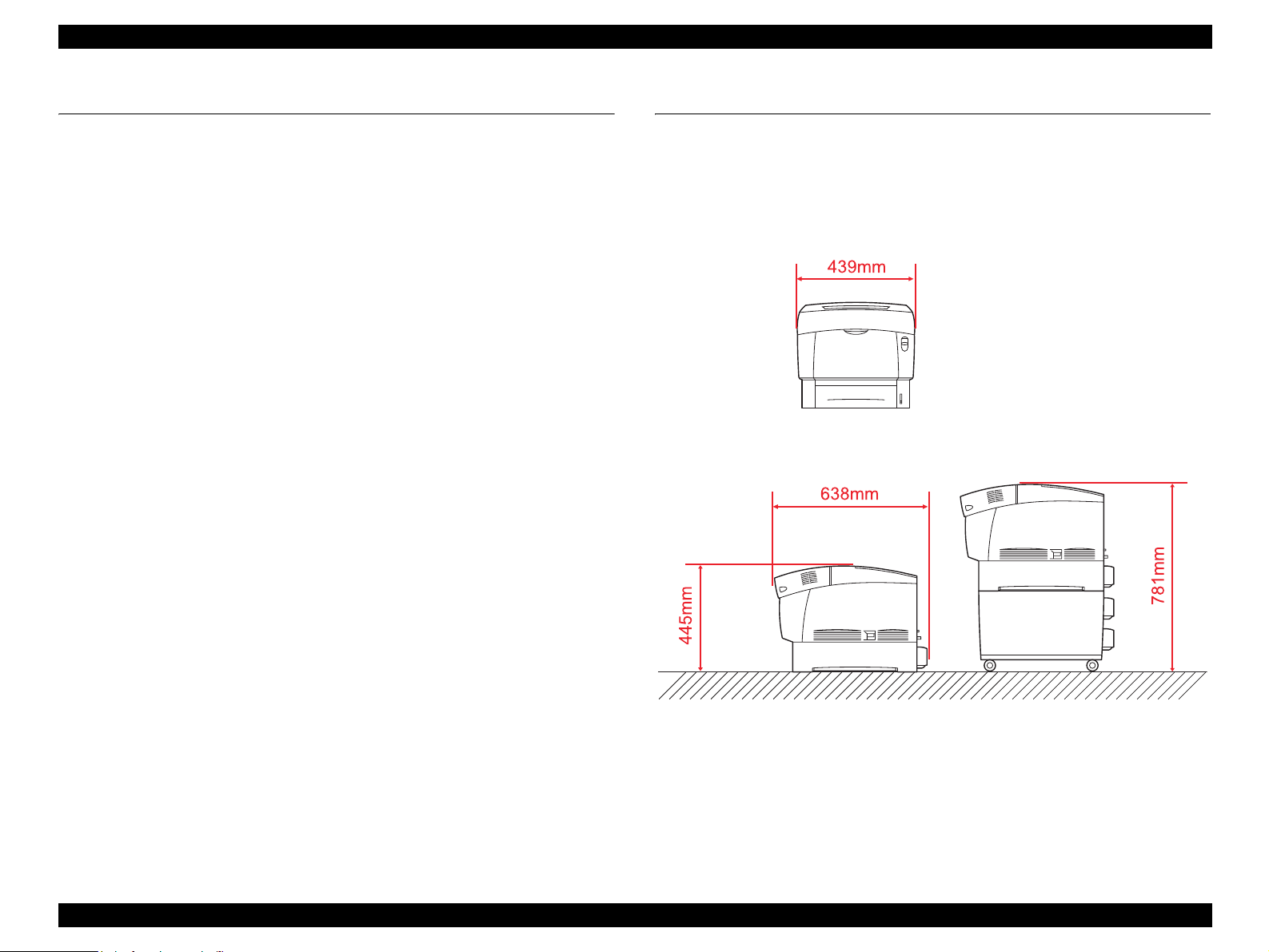
EPSON AcuLaser C4000/C4100/C3000 Revision F
1.15 About RAM Expansion
In case of an insufficient memory, the following errors occur in this printer:
“Mem Overflow”, “Image Optimum”, “Need Memory”, “Duplex Mem
Overflow”. In these cases, error processing listed below can possibly release
the errors.
Set the resolution to 300 dpi in the case of B/W printing.
In color printing, change the compression format to the non-reversible
compression.
Make the receive buffer size smaller.
Set an unused I/F to Off.
However, in order to surely avoid problems with an insufficient memory, it is
necessary to install additional memory.
1.16 Dimensions
Dimensions: 439mm x 638mm x 445mm (W x L x H)
439mm x 638mm x 781mm (Include the option feeder unit)
Mann: Approx. 36.5kg (Printer body only)
The dimension of EPSON AcuLaser C4000 is shown below.
Figure 1-10. Dimension of AcuLaser C4000
Product Descriptions About RAM Expansion 1-54
Page 71

OPERATING PRINCIPLES
CHAPTER
2
Page 72

EPSON AcuLaser C4000/C4100/C3000 Revision F
2.1 Print Process
2.1.1 Print Process Overview
This printer is a “full color laser printer” that uses the principle of
electrophotographic recording. Each YMCK color (yellow, magenta, cyan,
black) has its own special drum and developer that are used in tandem, three
Intermediate Data Transfer rollers are coordinated (2 IDT 1 rollers, 1 IDT 2
roller), and at the end of the process the layered color toner images produce a
full color print.
The major steps of the print process are described below:
1) Charging: The drum surfaces are charged with electricity.
2) Exposure: Image areas are exposed on drums with laser radiation.
3) Developing: Image areas on drums are developed with toner.
4) Primary transfer:
The toner image on drums is transferred to transfer rollers (IDT1).
5) Secondary transfer:
The toner images on primary transfer rollers (IDT 1) are transferred to the
secondary transfer roller (IDT 2).
6) Cleaning: Primary transfer rollers (IDT 1) are cleaned.
7) Tertiary transfer:
The complete four-color toner image on the secondary transfer roller (IDT
2) is transferred to the paper.
Figure 2-1. Print Process Overview
8) Cleaning: Secondary transfer roller (IDT 2) is cleaned.
9) Electrical charge removal: The electrical charge of the paper is discharged.
10) Fusing: Toner on the paper is fixed with heat and pressure.
11) Cleaning: Residual toner on the drums and transfer rollers is collected.
Operating Principles Print Process 2-56
Page 73
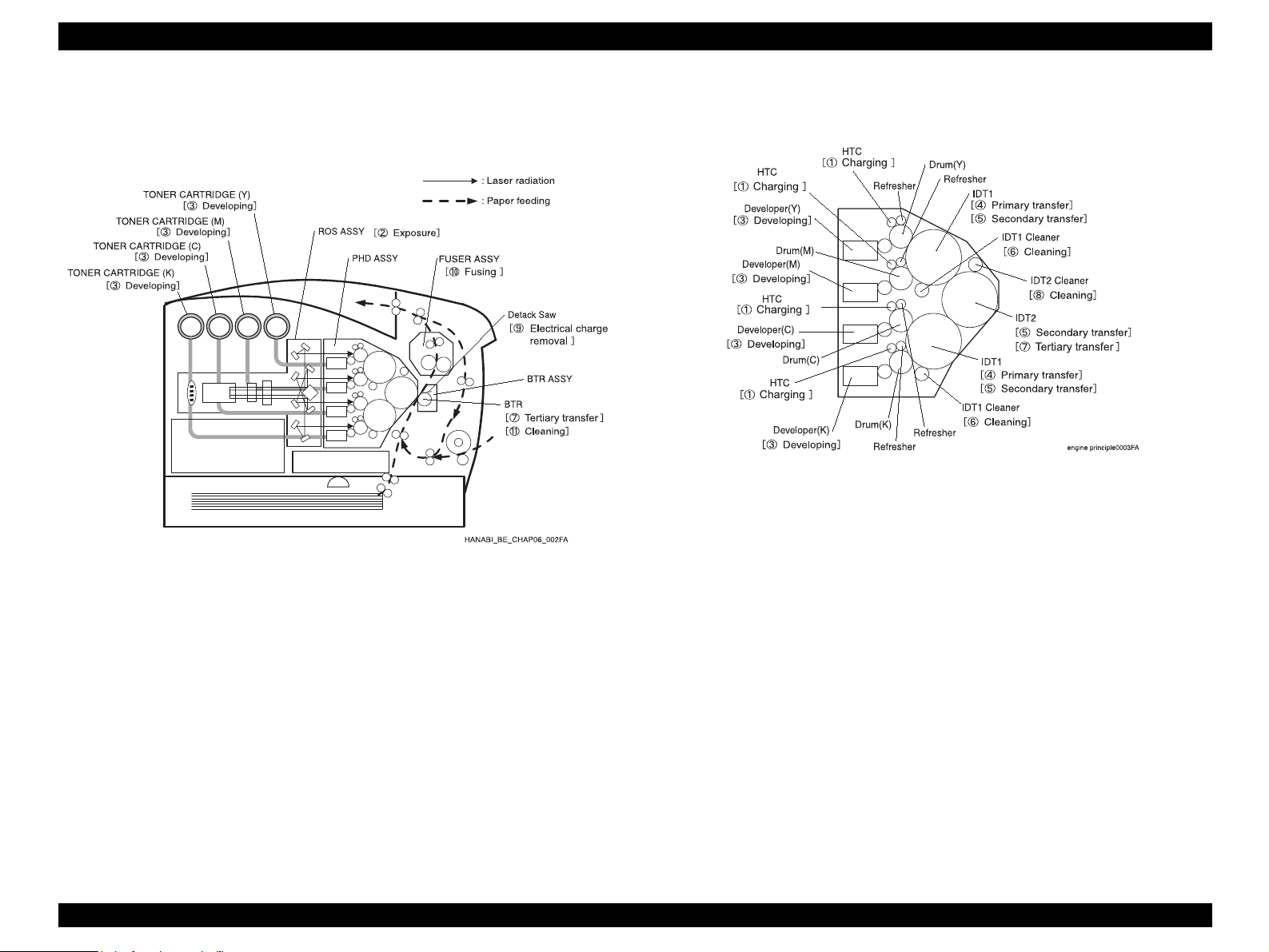
EPSON AcuLaser C4000/C4100/C3000 Revision F
2.1.2 Print Process Diagram
The diagram below illustrates the entire print process.
”
All major components of the printing process are consolidated in the PHD
ASSY (PL11.1.3), as shown in the diagram below.
Figure 2-3. PHD ASSY Diagram
Figure 2-2. Print Process Diagram
Operating Principles Print Process 2-57
Page 74

EPSON AcuLaser C4000/C4100/C3000 Revision F
2.1.3 Print Process Technical Explanation
2.1.3.1 Charging Process
This process gives an electrical charge to the surfaces of the photoconductive
drums.
2.1.3.2 Exposure Process
This process uses laser light to expose the imaging drums and form an
invisible electrostatic latent image on the drum surface.
2.1.3.3 Developing Process
This process builds up the images on the drum surfaces, using the toners.
2.1.3.4 Primary Transfer Process
This process transfers the toner images that have been built up on the drums,
to the Primary Intermediate Transfer Drums (IDT1).
2.1.3.5 Secondary Transfer Process
This process transfers the toner images from the Primary Intermediate
Transfer Drums (IDT1) to the Secondary Intermediate Transfer Drum (IDT2).
2.1.3.9 Electrical Carge Removal
This process neutralizes / removes any positive electrical charge that remains
on the back of the paper due to the “tertiary transfer”, through the provision of a
negative bias (negative voltage) by Detack Daw.
The removal of this electrostatic charge helps to prevent the paper from
sticking to, coiling around or being attracted toward the paper pathways, the
fuser and the paper eject tray. In addition, this procedure prevents image
disturbances that may be caused by electrical discharges and electrostatic
noise.
2.1.3.6 Cleaning
This process cleans the Primary Intermediate Transfer Drums (IDT1).
2.1.3.7 Tertiary Transfer Process
This process transfers the complete 4-color toner image from the Secondary
Intermediate Transfer Drum (IDT2) onto the paper.
2.1.3.8 Cleaning
This process cleans the Secondary Intermediate Transfer Drum (IDT2).
Operating Principles Print Process 2-58
Page 75

EPSON AcuLaser C4000/C4100/C3000 Revision F
2.1.3.10 Fusing Process
The “Fusing” process fixes the toner to the paper using heat and pressure.
The toner image that is transferred to the paper by IDT 2 can be easily
smudged by even a light touch of a finger, so the toner image is fixed to the
paper by the FUSER ASSY (PL9.1.1).
With the Heater Lamp as its heat source, the Heat Roll melts the toner,
then components inside the Belt opposite the Heat Roll applies pressure to
the paper and the toner is fixed in place.
The fusing method of the AcuLaser C4000 differs from previous heat-roll
and pressure-roll fusing methods. By using a pressure method with the
belt:
• Contact area for the Heat-Roll is expanded.
• Nip pressure is reduced by expansion of contact area.
• Heat transferability is improved by thinner Heat-Roll,
reducing warm-up time and fusing time.
2.1.3.11 Cleaning Process
This process recovers any excess toner that remains on the image drums and
on the intermediate transfer drums.
Figure 2-4. Fusing Process
Operating Principles Print Process 2-59
Page 76
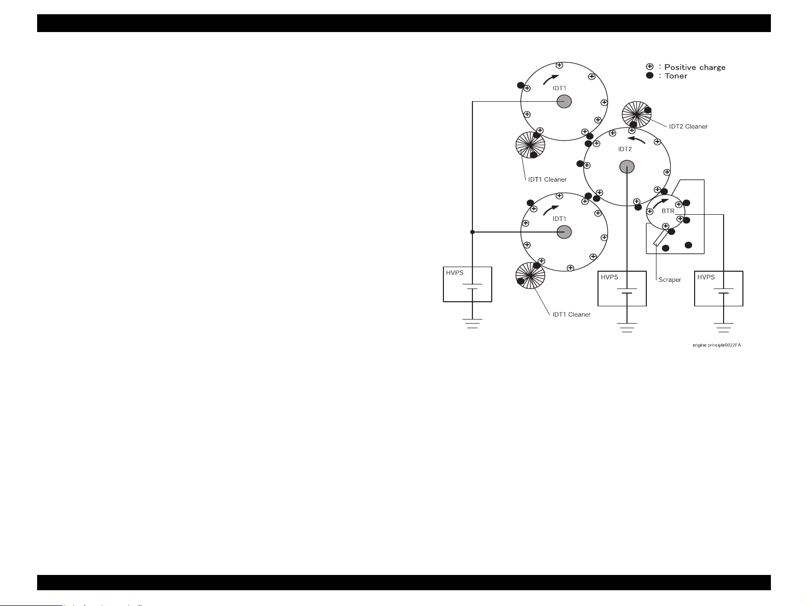
EPSON AcuLaser C4000/C4100/C3000 Revision F
2.1.3.12 Cleaning (Full)
The “Cleaning (Full)” process removes residual toner from the HTC, Refresher,
IDT 1 Cleaner, and IDT 2 Cleaner after the complete toner image has been
transferred to the paper.
Toner that is not transferred during the “Secondary Transfer” and “3rd
Stage Transfer” processes is retained on the IDT 1 Cleaner and IDT 2
Cleaner. The polarity also changes and toner returned to the drum is
retained on the Refresher. Any toner that slips by the Refresher adheres to
the HTC.
The toner in these locations is cleaned after completion of the print. The
method used to collect the toner on IDT 1 Cleaner and IDT 2 Cleaner is
different from the method used on the Refresher and HTC.
1) IDT 1 Cleaner, IDT 2 Cleaner
The same high voltage used during the print transfer process is applied
to IDT 1, IDT 2 and BTR. By applying zero volts to the IDT 1 Cleaner
and IDT 2 Cleaner, any remaining toner (negative polarity) on the IDT
cleaners is transferred by electric charge to IDT 1 and IDT 2. From that
point, as with the print transfer process, the electric potential difference
of IDT 1, IDT 2 and BTR causes the remaining toner to be collected on
the BTR surface.
Figure 2-5. Cleaning 1
Operating Principles Print Process 2-60
Page 77

EPSON AcuLaser C4000/C4100/C3000 Revision F
2) Refresher, HTC
High voltage opposite that used during the print transfer process
(negative) is applied to IDT 1, IDT 2 and BTR. The drum surfaces are
negatively charged by contact with IDT 1 rollers. By applying zero volts
to the Refresher and HTC, residual toner (positive polarity) on the
Refresher and HTC is transferred by electric charge to the drums. From
that point, as with the print transfer process, the electric potential
difference of IDT 1, IDT 2 and BTR causes the remaining toner to be
collected on the BTR surface.
Toner picked up by the BTR surface is scraped off by the Scraper and
collected in the toner collection space inside the BTR ASSY (PL9.1.2).
Figure 2-6. Cleaning 2
Operating Principles Print Process 2-61
Page 78

EPSON AcuLaser C4000/C4100/C3000 Revision F
2.2 Flow of Print Data
2.2.1 Data Flow
Print data (electric signal) from the Printer Controller follows the flow shown
below to become a print image.
Operating Principles Flow of Print Data 2-62
Page 79

EPSON AcuLaser C4000/C4100/C3000 Revision F
2.3 Drive Transmission Path
2.3.1 DRIVE ASSY MAIN (PL14.1.2)
Rotational force of the DRIVE ASSY MAIN is transferred through the flow
shown below.
Figure 2-8. DRIVE ASSY MAIN 2
Figure 2-7. DRIVE ASSY MAIN 2
Operating Principles Drive Transmission Path 2-63
Page 80

EPSON AcuLaser C4000/C4100/C3000 Revision F
2.3.2 DRIVE ASSY DEVE (PL14.1.1)
Rotational force of the DRIVE ASSY DEVE drives each of the color developers
inside the PHD ASSY (PL11.1.3).
Figure 2-9. DRIVE ASSY DEVE 1
2.3.3 HOLDER ASSY (PL12.2.5 ~ 8) (Y, M, C, K)
Rotational force of the Toner Motor inside the HOLDER ASSY drives the
Agitator inside the TONER CARTRIDGE (PL12.1.1~4) in order to supply toner
from the TONER CARTRIDGE to the HOLDER ASSY. It also drives the Auger
inside the HOLDER ASSY to supply toner to the Developer inside the PHD
ASSY (PL11.1.3). There are four HOLDER ASSY, one for each YMCK color,
and they all work the same way.
Figure 2-11. HOLDER ASSY 1
Figure 2-10. DRIVE ASSY DEVE 2
Operating Principles Drive Transmission Path 2-64
Page 81
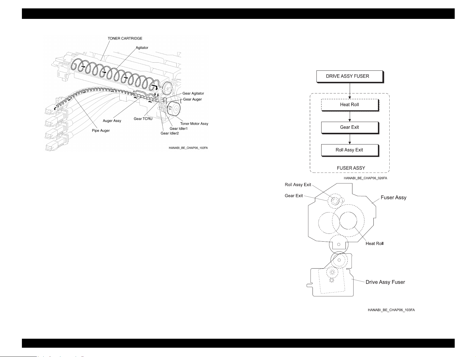
EPSON AcuLaser C4000/C4100/C3000 Revision F
2.3.4 DRIVE ASSY FUSER (PL6.1.18)
Rotational force of the DRIVE ASSY FUSER drives the FUSER ASSY
(PL9.1.1).
Figure 2-12. HOLDER ASSY 2
Figure 2-13. DRIVE ASSY FUSER
Operating Principles Drive Transmission Path 2-65
Page 82

EPSON AcuLaser C4000/C4100/C3000 Revision F
2.3.5 MOTOR ASSY DUP (PL8.1.8)
Rotational force of the MOTOR ASSY DUP is transferred through the flow
shown below.
Figure 2-15. MOTOR ASSY DUP 2
Figure 2-14. MOTOR ASSY DUP 1
Operating Principles Drive Transmission Path 2-66
Page 83

EPSON AcuLaser C4000/C4100/C3000 Revision F
2.4 Paper Feed
2.4.1 Paper Feed Path (without options in use)
2.4.2 Paper Feed Path Diagram
Figure 2-16. Paper Feed Path Diagram 1
Operating Principles Paper Feed 2-67
Page 84

EPSON AcuLaser C4000/C4100/C3000 Revision F
Figure 2-17. Paper Feed Path Diagram 2
Operating Principles Paper Feed 2-68
Page 85

EPSON AcuLaser C4000/C4100/C3000 Revision F
2.5 Functions of Main Components
The main components that make up this device will be explained with
corresponding illustrations.
Components are divided into blocks according to the structure of the printer.
Paper Cassette (PL3.1 ~ 2)
Paper Feeder (PL4.1 ~ 3)
Housing Assy Retard (PL5.1)
Chute Assy In (PL6.1)
Chute Assy Out (PL7.1)
Chute Assy Exit (PL8.1)
Fuser Assy & BTR Assy (PL9.1)
Xerographics (PL11.1)
TCRU Assy (PL12.1 ~ 3)
Frame (PL13.1) & Drive (PL14.1)
Figure 2-18. Functions of Main Components
Electrical (PL15.1 ~ 2) & CONTROLLER BOARD (ESS) (PL16.1)
2.5.1 Paper Cassette (PL3.1 ~ 2)
2.5.1.1 Main Functions
Side Guide
Adjusts to needed width for paper feed direction and maintains paper
position.
End Guide
Adjusts to needed width for paper feed direction and determines the paper
supply size. Paper size is detected when the End Guide position changes
the ON/OFF condition of the SWITCH SIZE TRAY 1 (PL4.2.8). (See
Section 2.5.2 Paper Feeder)
ROLL ASSY (Cassette) (PL3.1.6)
Paper is fed by the pinching action of the ROLL ASSY (Cassette) and
ROLL ASSY (PICK UP ASSY) (PL4.3.25). (See Section 2.5.2 Paper
Feeder)
Operating Principles Functions of Main Components 2-69
Page 86
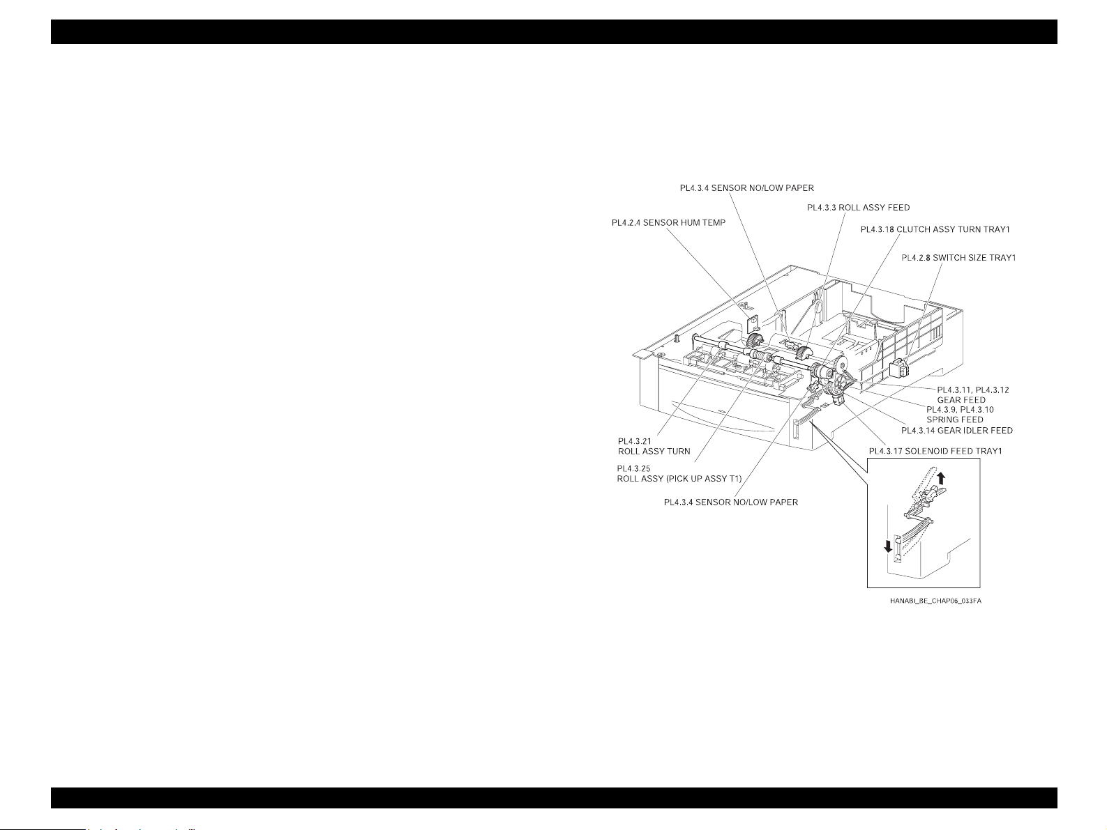
EPSON AcuLaser C4000/C4100/C3000 Revision F
2.5.2 Paper Feeder (PL4.1 ~ 3)
2.5.2.1 Main Functions
SWITCH SIZE TRAY1 (PL4.2.8)
SWITCH SIZE TRAY 1 detects the presence/absence of the tray and the
size of the paper.
SENSOR NO/LOW PAPER (No paper Sensor) (PL4.3.4)
Detects the presence/absence of paper inside the tray by change in the
actuator position. (No paper: sensor blocked)
SENSOR NO/LOW PAPER (Low Paper Sensor) (PL4.3.4)
The actuator lowers according to the level of paper in the tray. When the
actuator descends to a certain level, the sensor becomes shaded, thereby
allowing detection of the low quantity of paper.
The actuator position can be seen from the front of the tray, allowing a
rough estimate of remaining paper.
SOLENOID FEED TRAY1 (PL4.3.17)
The ROLL FEED ASSY (PL4.3.3) motion (rotating/stopped) is controlled
by the GEAR FEED (PL4.3.11, PL4.3.12) rotation.
CLUTCH ASSY TURN TRAY1 (PL4.3.18)
Driving force from the DRIVE ASSY MAIN (PL14.1.2) is transferred to the
ROLL ASSY TURN (PL4.3.21).
SENSOR HUM TEMP (PL4.2.4)
Detects temperature and humidity inside the printer.
The printer adjusts the charge voltage, the supply voltage to each transfer
roller, and the developer bias according to the detected temperature and
humidity.
ROLL ASSY FEED (PL4.3.3)
When the SOLENOID FEED TRAY 1 moves, force from the SPRING
FEED (PL4.3.9, PL4.3.10) causes the GEAR FEED and GEAR IDLER
FEED (PL4.3.14) to engage, the ROLL ASSY FEED begins rotating by
receiving driving force from the DRIVE ASSY MAIN, and the ROLL ASSY
(PICK UP ASSY) (PL4.3.25) feeds a sheet of paper from the tray. A notch
in the GEAR FEED causes the GEAR FEED and GEAR IDLER FEED to
disengage after one revolution, cutting the transfer of force and stopping
rotation of the ROLL ASSY FEED. In this way, one sheet of paper is fed at
a time.
Figure 2-19. Paper Feeder
ROLL ASSY TURN (PL4.3.21)
ROLL ASSY TURN begins turning by receiving driving force from DRIVE
ASSY MAIN through CLUTCH ASSY TURN TRAY 1 and conveys the
paper fed from the tray to the CHUTE REGI (Regi Roll) (PL10.1.14). (See
Section 2.5.8 Xerographics)
Operating Principles Functions of Main Components 2-70
Page 87
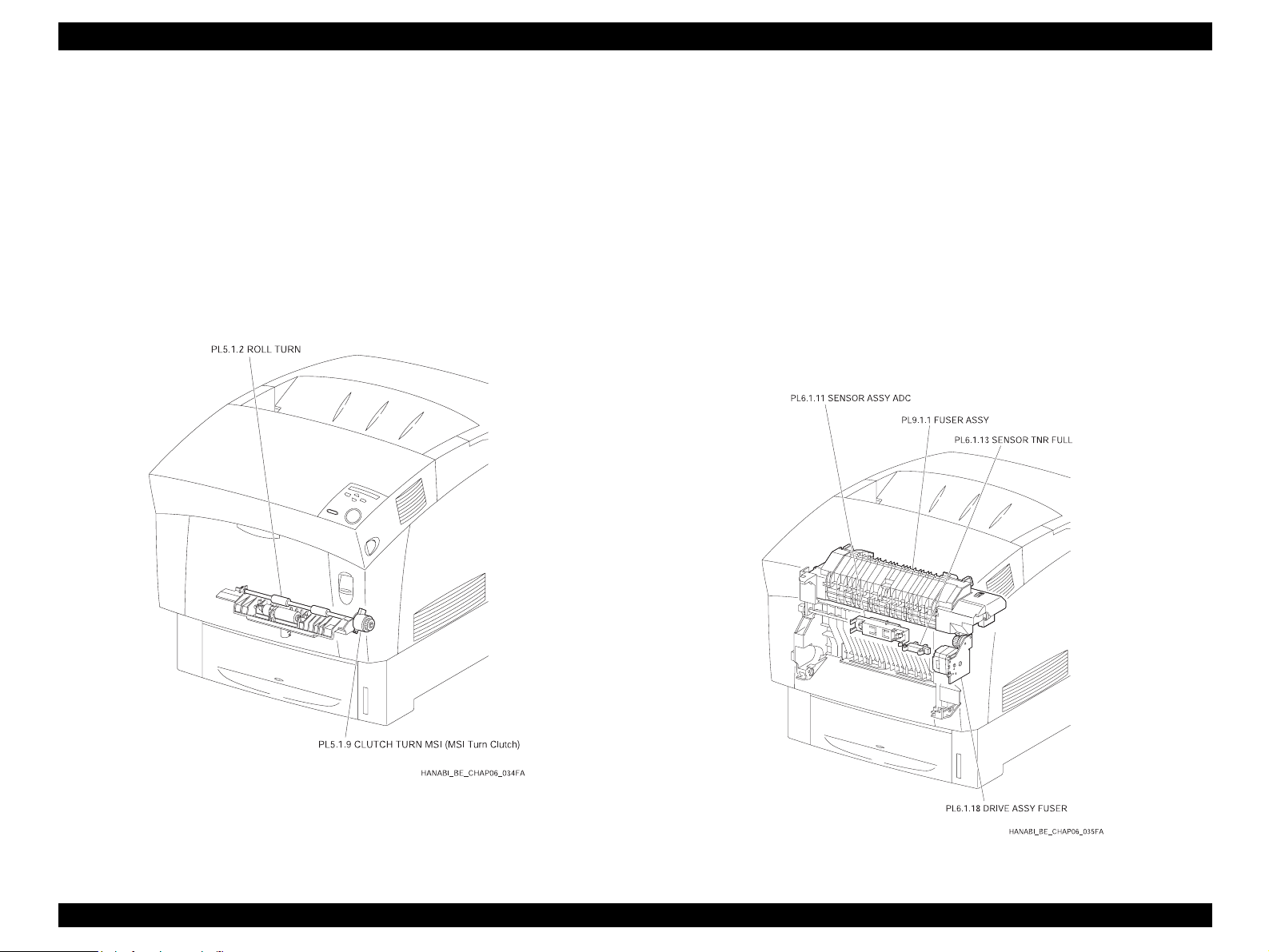
EPSON AcuLaser C4000/C4100/C3000 Revision F
2.5.3 Housing Assy Retard (PL5.1)
2.5.3.1 Main Functions
CLUTCH TURN MSI (MSI Turn Clutch) (PL5.1.9)
Driving force from the DRIVE ASSY MAIN (PL14.1.2) is transferred to the
ROLL TURN (PL5.1.2).
ROLL TURN (PL5.1.2)
ROLL TURN begins turning by receiving driving force from DRIVE ASSY
MAIN through CLUTCH TURN MSI (MSI Turn Clutch) and conveys the
paper fed from the tray to the CHUTE REGI (Regi Roll) (PL10.1.14). (See
Section 2.5.8 Xerographics)
2.5.4 Chute Assy In (PL6.1)
2.5.4.1 Main Functions
SENSOR ASSY ADC (PL6.1.11)
Determines the density of the toner image on the surface of the BTR inside
the BTR ASSY (PL9.1.2) (See 5.7 FUSER ASSY & BTR ASSY) and sends
that feedback to the Process Controller. (See Section 2.8.4 PROCESS
CONTROLLER)
SENSOR TNR FULL (PL6.1.13)
Detects the “full” condition of the BTR ASSY waste toner collection space.
(See Section 2.5.7 FUSER ASSY & BTR ASSY)
DRIVE ASSY FUSER (PL6.1.18)
Supplies driving force to the FUSER ASSY (PL9.1.1). (See Section 2.5.7
FUSER ASSY & BTR ASSY)
Figure 2-20. Housing Assy Retard
Figure 2-21. Chute Assy In
Operating Principles Functions of Main Components 2-71
Page 88

EPSON AcuLaser C4000/C4100/C3000 Revision F
2.5.5 Chute Assy Out (PL7.1)
2.5.5.1 Main Functions
SENSOR PAPER (Full Stack Sensor) (PL7.1.4)
Change in the actuator position detects exceeded quantities of discharged
or collected paper on the top cover.
(Full stack: sensor receiving)
SENSOR PAPER (Dup Jam Sensor) (PL7.1.4)
Change in the actuator position detects if the paper has reached or is
passing through the ROLL DUP (PL7.1.12).
(Paper present: sensor receiving)
SENSOR PAPER (MSI No Paper Sensor) (PL7.1.4)
Change in the actuator position detects presence/absence of paper on the
manual feed tray.
(Paper absent: sensor blocked)
SOLENOID FEED MSI (PL7.1.40)
The ROLL ASSY FEED (PL7.1.27) motion (rotating/stopped) is controlled
by the GEAR MSI (PL7.1.22) rotation.
ROLL ASSY FEED (PL7.1.27)
When the SOLENOID FEED MSI moves, force from the SPRING SOL
(PL7.1.39) causes the GEAR MSI and GEAR IDLER (DRIVE MAIN ASSY)
to engage, the ROLL ASSY FEED begins rotating by receiving driving
force from the DRIVE ASSY MAIN (PL14.1.2) and feeds a sheet of paper
from the manual feed tray.
A notch in the GEAR MSI causes the GEAR MSI and GEAR Idler (DRIVE
ASSY MAIN) to disengage after one revolution, cutting the transfer of force
and stopping rotation of the ROLL ASSY FEED. In this way, one sheet of
paper is fed at a time.
Figure 2-22. Chute Assy Out
ROLL DUP (PL7.1.12)
ROLL DUP begins rotating by receiving driving force from MOTOR ASSY
DUP (PL8.1.8) and then conveys single-side printed paper from the
CHUTE ASSY EXIT (PL8.1.1) to the ROLL TURN (PL5.1.2). (See Section
2.5.3 HOUSING ASSY RETARD)
Operating Principles Functions of Main Components 2-72
Page 89
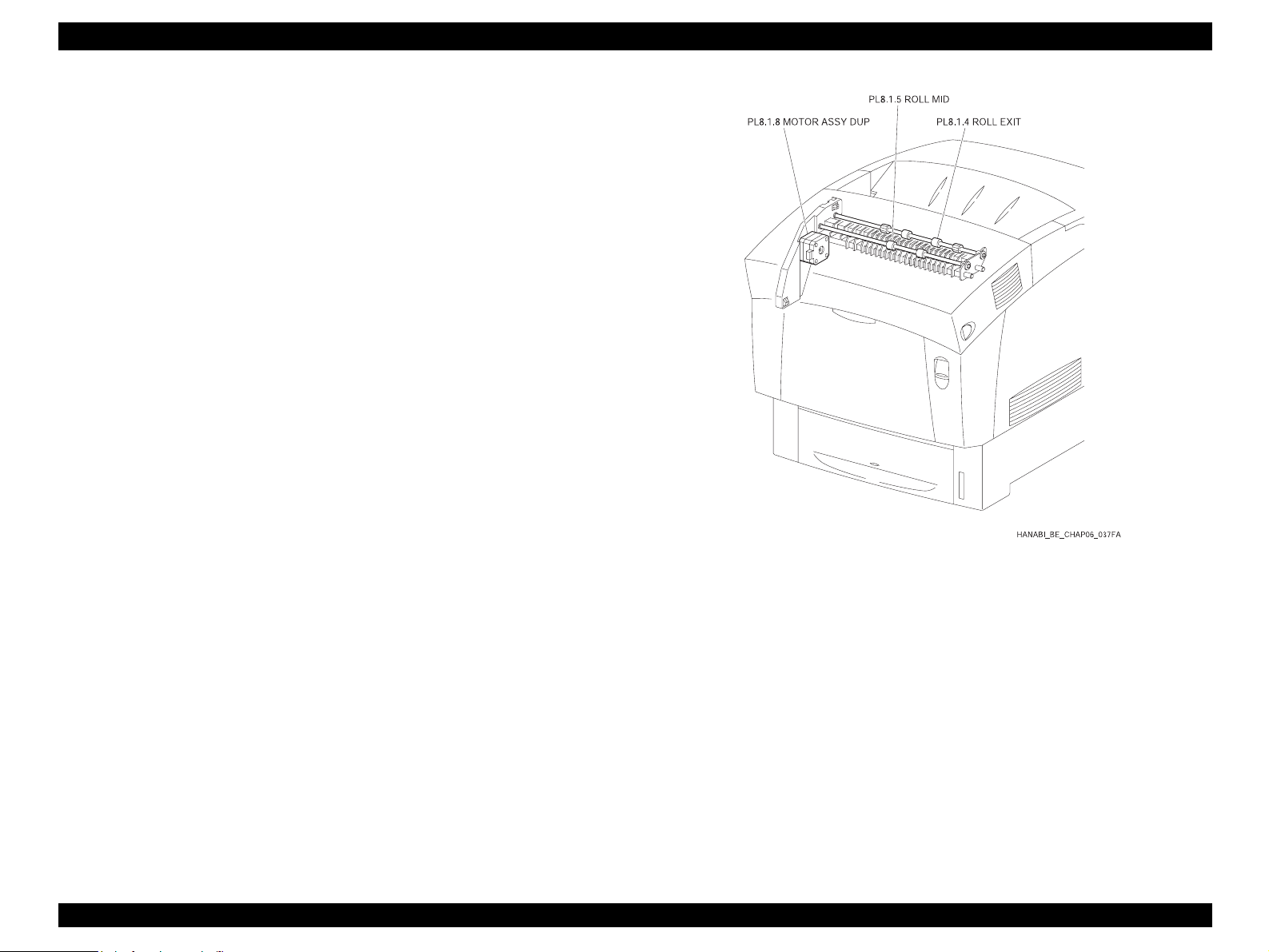
EPSON AcuLaser C4000/C4100/C3000 Revision F
2.5.6 Chute Assy Exit (PL8.1)
2.5.6.1 Main Functions
MOTOR ASSY DUP (PL8.1.8)
Supplies driving force to the ROLL EXIT (PL8.1.4), ROLL MID (PL8.1.5),
ROLL DUP (PL7.1.12).
ROLL EXIT (PL8.1.4)
ROLL EXIT begins rotating by receiving driving force from MOTOR ASSY
DUP and then conveys the fused print onto the top cover. For double-sided
printing, ROLL EXIT reverses rotation and conveys the single-side printed
paper toward the REGI.
ROLL MID (PL8.1.5)
ROLL MID begins rotating by receiving driving force from MOTOR ASSY
DUP and then conveys the fused print onto the top cover. For double-sided
printing, ROLL EXIT reverses rotation and conveys the single-side printed
paper toward the REGI.
Figure 2-23. Chute Assy Exit
Operating Principles Functions of Main Components 2-73
Page 90

EPSON AcuLaser C4000/C4100/C3000 Revision F
2.5.7 Fuser Assy & BTR Assy (PL9.1)
2.5.7.1 Main Functions
FUSER ASSY (PL9.1.1)
The FUSER ASSY fixes the toner to the paper with heat and pressure, and
it also conveys the paper toward and away from the fusing location.
The FUSER ASSY is constructed of the following main components:
• Heat Roll • Belt Unit
• Heater Lamp • Roll Assy Exit
• Thermostat • Exit Sensor
• Temp Sensor
Exit Sensor
Change in the actuator position detects passage of the paper after the
image is fused.
BTR ASSY (PL9.1.2)
The BTR ASSY is constructed of the BTR (Bias Transfer Roll) and the
waster toner collection system.
The BTR is positioned opposite IDT 2 of the PHD ASSY (PL11.1.3) and
transfers the toner image on IDT 2 to the paper.
FAN FUSER (PL1.1.9)
Vents heat from FUSER ASSY and prevents inside the printer overheating.
Figure 2-24. Fuser Assy & BTR Assy 1
Operating Principles Functions of Main Components 2-74
Page 91
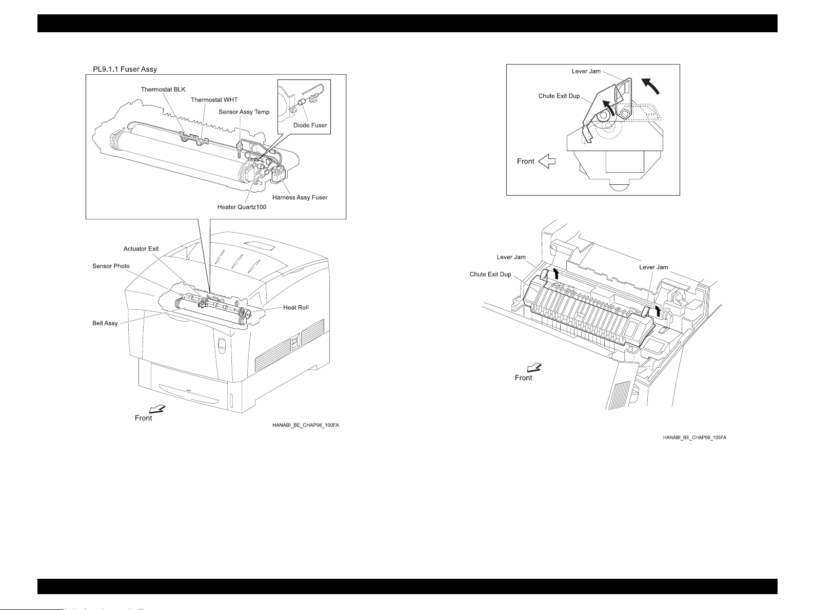
EPSON AcuLaser C4000/C4100/C3000 Revision F
Figure 2-25. Fuser Assy & BTR Assy 2
Operating Principles Functions of Main Components 2-75
Figure 2-26. Fuser Assy & BTR Assy 3
Page 92

EPSON AcuLaser C4000/C4100/C3000 Revision F
Figure 2-27. Fuser Assy & BTR Assy 4
Operating Principles Functions of Main Components 2-76
Page 93

EPSON AcuLaser C4000/C4100/C3000 Revision F
2.5.8 Xerographics (PL11.1)
2.5.8.1 Main Functions
ROS ASSY (PL11.1.1)
The ROS ASSY (Raster Output Scanner Assembly) is an exposure device
that sends out laser radiation to form electrostatic images on the surface of
the drum.
In this manual, items related to the ROS ASSY are simply called ROS.
The ROS ASSY is constructed of the following main components:
• Quad Beam Laser Diode
• Scanner Motor Assy
• SOS PWB
• Lens
• Mirror
• Window
PHD ASSY (PL11.1.3)
The PHD ASSY (Print Head Assembly) handles the charging, developing
and transferring steps of the print process.
The PHD ASSY is constructed of the following components:
• Drum (Y) • Developer (Y)
CHUTE ASSY REGI (CLUTCH REGI) (PL10.1.1)
The CHUTE ASSY REGI is constructed of the CLUTCH REGI (PL10.1.12),
the ROLL REGI RUBBER (PL10.1.10) and the ROLL REGI METAL.
Driving force is transferred from the DRIVE ASSY MAIN (PL14.1.2) to the
ROLL REGI RUBBER by the CLUTCH REGI (PL10.1.12), and the paper is
conveyed toward the PHD ASSY from either the Tray path or the MSI path.
In addition, when the leading edge of the paper reaches the CHUTE REGI
(PL10.1.14), the CLUTCH REGI becomes a retaining loop for the paper
until the ROLL REGI RUBBER begins rotating, and it corrects skew of the
paper edge to ensure proper feed.
SENSOR REGI (Regi Sensor) (PL10.1.20)
Detects the leading edge of the paper when it reaches the CHUTE REGI.
(Paper present: sensor receiving)
SENSOR OHP (PL10.1.16)
Regular paper scatters radiated light, and the SENSOR OHP catches that
reflected light, detecting the paper. OHP (Over Head Projector)
transparencies do not scatter much direct light, so the SENSOR OHP
cannot catch any reflected light. This method determines if the sheet being
fed from the MSI is an OHP transparency or regular paper.
• Drum (M) • Developer (M)
• Drum (C) • Developer (C)
• Drum (K) • Developer (K)
• HTC (Y) • Refresher (Y)
• HTC (M) • Refresher (M)
• HTC (C) • Refresher (C)
• HTC (K) • Refresher (K)
• IDT 1 (2) • IDT 2
• IDT 1 Cleaner (2) • IDT 2 Cleaner
Figure 2-28. Xerographics
Operating Principles Functions of Main Components 2-77
Page 94

EPSON AcuLaser C4000/C4100/C3000 Revision F
2.5.9 TCRU Assy (PL12.1 ~ 3)
2.5.9.1 Main Functions
SWITCH TCRU ASSY (Y) (PL12.2.10)
SWITCH TCRU ASSY (M) (PL12.2.10)
SWITCH TCRU ASSY (C) (PL12.2.10)
SWITCH TCRU ASSY (K) (PL12.2.10)
Detects the presence/absence of TCRU ASSY (toner bottle) for each color.
SENSOR TONER LOW (Y) (PL12.2.9)
SENSOR TONER LOW (M) (PL12.2.9)
SENSOR TONER LOW (C) (PL12.2.9)
SENSOR TONER LOW (K) (PL12.2.9)
Detects the toner quantity for each color.
HOLDER ASSY (Y) (Toner Motor : Y) (PL12.2.5)
HOLDER ASSY (M) (Toner Motor : M) (PL12.2.6)
HOLDER ASSY (C) (Toner Motor : C) (PL12.2.7)
HOLDER ASSY (K) (Toner Motor : K) (PL12.2.8)
The Toner Motor built into each HOLDER ASSY drives the Agitator inside
the TCRU ASSY and the Auger inside the HOLDER ASSY, thereby
supplying toner to the Developers in the PHD ASSY (PL11.1.3).
HVPS SUB (PL12.1.9)
Provides high voltage to the following components during “3rd Stage
Transfer” and “De-electrification” of the print process.
• The BTR inside the BTR ASSY (PL9.1.2)
• The Detack Saw inside the BTR ASSY (PL9.1.2)
TONER CARTRIDGE (Y) (PL12.1.1)
TONER CARTRIDGE (M) (PL12.1.2)
TONER CARTRIDGE (C) (PL12.1.3)
TONER CARTRIDGE (K) (PL12.1.4)
The toner for each color is contained in the built-in toner bottle.
PWB EEPROM (PL12.1.8)
Stores printer dedicated data.
Figure 2-29. TCRU Assy
Operating Principles Functions of Main Components 2-78
Page 95

EPSON AcuLaser C4000/C4100/C3000 Revision F
2.5.10 Frame (PL13.1) & Drive (PL14.1)
2.5.10.1 Main Functions
DRIVE ASSY MAIN (PL14.1.2)
Supplies driving force to the following components:
• PAPER FEEDER (PL4.1 ~3)
• HOUSING ASSY RETARD (PL5.1.1)
• CHUTE ASSY OUT (MSI component) (PL7.1.1)
• CHUTE ASSY REGI (PL10.1.1)
• PHD ASSY (IDT 2, IDT 1, Drum) (PL11.1.3)
• BTR ASSY (PL9.1.2)
DRIVE ASSY DEVE (PL14.1.1)
Supplies driving force to the following components:
•PHD ASSY (Developer) (PL11.1.3)
2.5.11 Electrical (PL15.1 ~ 2) & CONTROLLER
BOARD (ESS) (PL16.1)
2.5.11.1 Main Functions
FAN REAR (PL15.1.3)
Vents heat from inside the printer and prevents internal overheating.
HARNESS ASSY AC SW (PL15.1.11)
Made up of the Main Switch and the Inlet, this controls supply of AC power
from the power source to LVPS (PL15.1.10).
LVPS (PL15.1.10)
There are two types of LVPS: for 100/200V and for 230V.
It provides AC power from the power source to the heater of the FUSER
ASSY (PL9.1.1) and also supplies stable low voltage DC power for use by
such components as the logic circuits.
PWBA MCU & HVPS (PL15.1.2)
Controls print operations based on PRINT CONTROLLER
communications and data from sensors and switches. HVPS is built into
the printer.
HVPS has the following main functions:
• Communications with PRINT CONTROLLER
• Reception of sensor/switch data
• Control of ROS ASSY (PL11.1.1)
To support “Charging”, “Developing”, “Primary Transfer” and “Secondary
Transfer” of the print process, the HVPS supplies high voltage to the
following components of the PHD ASSY (PL11.1.3):
• HTC
• Refresher
• Developer
• IDT 1
• IDT 2
• IDT 1 Cleaner
• IDT 2 Cleaner
Figure 2-30. Frame & Drive
Operating Principles Functions of Main Components 2-79
Page 96

EPSON AcuLaser C4000/C4100/C3000 Revision F
PWB DRIVE (PL15.1.15)
Controls the motor and other components according to PWBA MCU &
HVPS signals and sends data from sensors/switches to PWBA MCU &
HVPS. Power from the LVPS passes through this PWB and is supplied to
PWBA MCU & HVPS. This PWB is equipped with an interlock switch.
PWB DRIVE has the following main functions:
• Reception of data from sensors/switches
• Control of DRIVE ASSY MAIN (PL14.1.2), DRIVE ASSY DEVE
(PL14.1.1), DRIVE ASSY FUSER (PL6.1.18), MOTOR ASSY DUP
(PL8.1.8), and Toner Motors in HOLDER ASSY (PL12.2.5~8)
• Distribution of low voltage DC power from LVPS to each component
• Interruption of “24VDC” circuits by interlock switch activation
PWB CONTROLLER (PWB ESS) (PL16.1.5)
Receives data from the host computer, executes printing, and has overall
control of the printer.
Figure 2-31. Electrical & CONTROLLER BOARD (ESS)
Operating Principles Functions of Main Components 2-80
Page 97
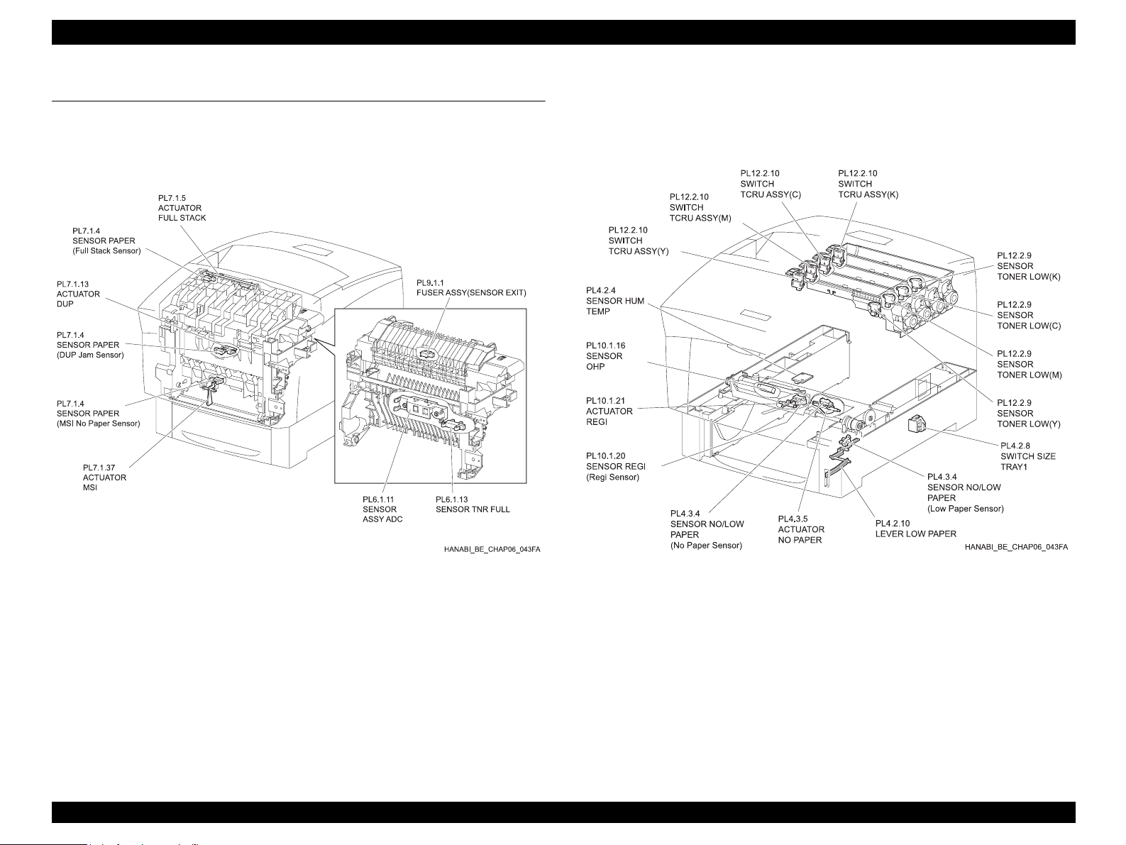
EPSON AcuLaser C4000/C4100/C3000 Revision F
2.6 Switches and Sensors
Switches and sensors installed on this printer are shown in the diagrams
below. For the function of each component, see “2.5 "Functions of Main
Components".
Figure 2-32. Switches and Sensors 1
Operating Principles Switches and Sensors 2-81
Figure 2-33. Switchse and Sensors 2
Page 98

EPSON AcuLaser C4000/C4100/C3000 Revision F
2.7 Mode
2.7.1 Print Mode
There are three print modes: Normal Mode, High Resolution Mode, and High
Gloss Mode. These modes have sub-categories based on resolution (600 dpi/
1200 dpi) and process speed (full speed/half speed).
When process speed is set to half speed, video data transfer speed to the ROS
is double the 600 dpi speed, yielding 1200 dpi resolution.
1. Use Normal Mode to print at 600 dpi
2. Use High Resolution Mode to print at 1200 dpi on plain paper
3. Use High Gloss Mode at 600 dpi with half speed to improve gloss on plain
paper
Relationships of resolution, process speed, paper and print mode are shown
below.
Table 2-1. Print Mode
Resolution / Process speed
Paper Print Mode
Normal
600dpi 1200dpi
Simplex Duplex Simplex Duplex
Full
Speed
Full
Speed
––
2.7.2 Operation Mode
The following five modes are available in the printer’s Operation Mode.
DIAG TEST Mode
Printer is ready to receive diagnostic commands or is executing
diagnostics.
WAIT Mode
Printer is adjusting print quality.
READY Mode
Printer is ready to print.
PRINTING Mode
Printer is printing.
ERROR Mode
Printer has detected some kind of problem.
Normal Paper
Special
Applications *
High Resolution – –
High Gloss
Normal
1
Half
Speed
Half
Speed
High Resolution ––
Half
Speed
Half
Speed
– – –
––
Half
Speed
Half
Speed
–
*1: Thick paper, Labels, Transparencies, Envelopes, Postcards
Operating Principles Mode 2-82
Page 99

EPSON AcuLaser C4000/C4100/C3000 Revision F
2.8 Control
2.8.1 Paper Size Control
The table below shows “Paper Size Switch ON/OFF conditions for SWITCH
SIZE TRAY 1 (PL4.2.8)” and corresponding “Diagnostic Tool Display Data”
according to the paper size loaded.
NOTE: Paper size switch order from the highest to lowest positions is
“SW1”, “SW2”, “SW3”.
Table 2-2. Paper Size Control
Paper Size
LEGAL14” (SEF) ON ON ON 00
LEGAL13” (SEF) ON ON OFF 01
EXECUTIVE (SEF) ON OFF ON 02
B5 (SEF) ON OFF OFF 03
A4 (SEF) OFF ON ON 04
LETTER (SEF) OFF OFF ON 06
Paper Size Switch
SW1 SW2 SW3
Diagnostic Display
Data
2.8.2 Paper Supply Selection Control
When not actively controlled by the Printer Controller, TRAY 1 is selected as
the paper supply when the power is turned ON.
NOTE: “TRAY 1” is used as the name for the printer’s internal paper
supply, “TRAY 2” is the first level of the optional TRAY UNIT and
“TRAY 3” is the second level of the TRAY UNIT.
2.8.3 ROS Light Control
Image data enters the laser diode of the ROS ASSY as an electric signal (data
is expressed by high/low condition of the voltage), and the laser diode converts
that electric signal to a light signal (data is expressed by on/off condition of the
light).
Occurrence of variations such as fluxuations in laser radiation quantity,
irregularities in the optics (such as the lens) or variations in the sensitivity of the
drum can prevent the formation of a suitable electrostatic image, so the laser
diode monitors the laser radiation quantity and controls it in order to always
obtain a suitable electrostatic image.
The ROS in this printer has four separate laser diodes, one each for yellow,
magenta, cyan and black, and quantity of laser radiation is automatically
adjusted for each.
A5 OFF ON ON
No cassette OFF OFF OFF 07
Operating Principles Control 2-83
Page 100
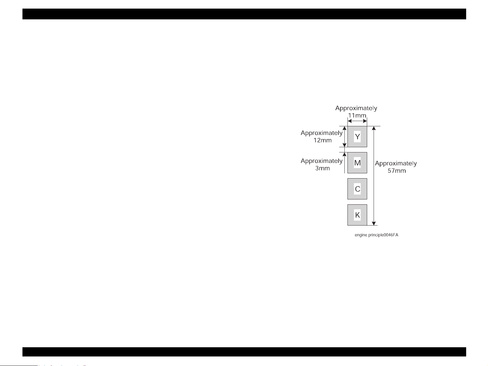
EPSON AcuLaser C4000/C4100/C3000 Revision F
2.8.4 PROCESS CONTROL
In order to render a stable print, timely correction of image formation
parameters is needed. Control of the entire process that includes parameter
adjustment control is called “PROCESS CONTROL”.
The following two items are the main controlling functions:
• Potential Control
• Toner Density Control
The controlling functions above are supplemented by the following functions:
• High Area Coverage Mode
• Admix Mode
• SENSOR ASSY ADC (PL6.1.11) LED Light Quantity Setting
2.8.4.1 POTENTIAL CONTROL
In order to obtain stable print image density, POTENTIAL CONTROL regulates
the drum charge voltage and the developer DC voltage to match the fluctuating
developer capability moment by moment.
Adjusted drum charge voltage and developer DC voltage is monitored, and a
fixed level of print image density is maintained.
An overview of POTENTIAL CONTROL is shown below.
1) Temperature and humidity is measured by the SENSOR HUM TEMP
(PL4.2.4) and target values are set for drum charge voltage and
developer DC voltage.
2) A POTENTIAL CONTROL patch for each color (yellow, magenta, cyan,
black) is formed and transferred to the BTR surface. (The shape of the
patches is shown below.)
POTENTIAL CONTROL performs its functions just before printing starts under
the following conditions:
• When printing the first page after power has been turned on
• When the number of pages lined up for printing is 16 or more
• When performing a cleaning cycle between a series of pages to be
printed
3) Density on the portion of the BTR surface not holding toner and density
of the patch are both measured by the SENSOR ASSY ADC (Density
Sensor).
4) Density measurements taken at Step 3) are compared with target values
set in Step 1). Adjustments to drum charge voltage and developer DC
voltage for each color are made according to the difference in the
values.
Figure 2-34. POTENTIAL CONTROL
Operating Principles Control 2-84
 Loading...