


®
SERVICE MANUAL
Color Inkjet Printer
Stylus C40UX/C40SX/C20UX/C20SX
SEIJ01002

Notice
All rights reserved. No p art of t his manual may be reprod uced, stored i n a ret rieval sy stem, or t ransmit ted in any form or by a ny means el ectroni c,
mechanical, photocopying, or otherwise, without the prior written permission of SEIKO EPSON CORPORATION.
All effort have been made to ensure the accuracy of the contents of this manual. However, should any errors be detected, SEIKO EPSON would
greatly appreciate being informed of them.
The contents of this manual are subject to change witho ut notice.
The above not withstanding SEIKO EPSON CORPORATION can assume no responsibility for any errors in this manual or the consequences
thereof.
EPSON is a registered trademark of SEIKO EPSON CORPORATION.
General Notice: Other product names used herein are for identification purpose only and may be trademarks or registered trademarks of their
respective owners. EPSON disclaims any and all rights in those marks.
Copyright © 2001 SEIKO EPSON CORPORA TION.
Imaging & Information Product Division
TPCS Quality Assurance Department

PRECAUTIONS
Precautionary notations throughout the text are categorized relative to 1)Personal injury and 2) damage to equipment.
DANGER Signals a precaution which, if ignored, could result in serious or fatal personal injury. Great caution should be exercised in performing
procedures preceded by DANGER Headings.
WARNING Signals a precaution which, if ignored, could result in damage to equipment.
The precautionary measures itemized below should always be observed when performing repair/maintenance procedures.
DANGER
1. ALWAYS DISCONNECT THE PRODUCT FROM THE POWER SOURCE AND PERIPHERAL DEVICES PERFORMING ANY MAINTENANCE OR REPAIR
PROCEDURES.
2. NO WORK SHOULD BE PERFORMED ON THE UNIT BY PERSONS UNFAMILIAR WITH BASIC SAFETY MEASURES AS DICTATED FOR ALL ELECTRONICS
TECHNICIANS IN THEIR LINE OF WORK.
3. WHEN PERFORMING TESTING AS DICTATED WITHIN THIS MANUAL, DO NOT CONNECT THE UNIT TO A POWER SOURCE UNTIL INSTRUCTED TO DO SO.
WHEN THE POWER SUPPLY CABLE MUST BE CONNECTED, USE EXTREME CAUTION IN WORKING ON POWER SUPPLY AND OTHER ELECTRONIC
COMPONENTS.
4. WHEN DISASSEMBLING OR ASSEMBLING A PRODUCT, MAKE SURE TO WEAR GLOVES TO AVOID INJURIER FROM METAL PARTS WITH SHARP EDGES.
WARNING
1. REPAIRS ON EPSON PRODUCT SHOULD BE PERFORMED ONLY BY AN EPSON CERTIFIED REPAIR TECHNICIAN.
2. MAKE CERTAIN THAT THE SOURCE VOLTAGES IS THE SAME AS THE RATED VOLTAGE, LISTED ON THE SERIAL NUMBER/RATING PLATE. IF THE EPSON
PRODUCT HAS A PRIMARY AC RATING DIFFERENT FROM AVAILABLE POWER SOURCE, DO NOT CONNECT IT TO THE POWER SOURCE.
3. ALWAYS VERIFY THAT THE EPSON PRODUCT HAS BEEN DISCONNECTED FROM THE POWER SOURCE BEFORE REMOVING OR REPLACING PRINTED
CIRCUIT BOARDS AND/OR INDIVIDUAL CHIPS.
4. IN ORDER TO PROTECT SENSITIVE MICROPROCESSORS AND CIRCUITRY, USE STATIC DISCHARGE EQUIPMENT, SUCH AS ANTI-STATIC WRIST STRAPS,
WHEN ACCESSING INTERNAL COMPONENTS.
5. DO NOT REPLACE IMPERFECTLY FUNCTIONING COMPONENTS WITH COMPONENTS WHICH ARE NOT MANUFACTURED BY EPSON. IF SECOND SOURCE IC
OR OTHER COMPONENTS WHICH HAVE NOT BEEN APPROVED ARE USED, THEY COULD CAUSE DAMAGE TO THE EPSON PRODUCT, OR COULD VOID THE
WARRANTY OFFERED BY EPSON.

About This Manual
This manual describes basic functions, theory of electrical and mechanical operations, maintenance and repair procedures of the printer. The instructions and
procedures included herein are intended for the experienced repair technicians, and attention should be given to the precautions on the preceding page.
Manual Configuration
This manual consists of six chapters and Appendix.
CHAPTER 1. PRODUCT DESCRIPTIONS
Provides a general overview and specifications of the
product.
CHAPTER 2. OPERATING PRINCIPLES
Describes the theory of electrical and mechanical
operations of the product.
CHAPTER 3. TROUBLESHOOTING
Describes the step-by-step procedures for the
troubleshooting.
CHAPTER 4. DISASSEMBLY / ASSEMBLY
Describes the step-by-step procedures fo r disassembling
and assembling the product.
CHAPTER 5. ADJUSTMENT
Provides Epson-approved methods for adjustment.
CHAPTER 6. MAINTENANCE
Provides preventive maintenance procedures and the
lists of Epson-approved lubricants and adhesives
required for servicing the product.
APPENDIX Provides the following additional information for
reference:
• Connector pin assignments
• Electric circuit boards components layout
• Electrical circuit boards schematics
• Exploded diagram & Parts List
Symbols Used in this Manual
Various symbols are used throughout this manual either to provide
additional information on a specific topic or to warn of possible danger
present during a procedure or an action. Be aware of all symbols when
they are used, and always read NOTE, CAUTION, or WARNING
messages.
A D J U S T M E N T
R E Q U I R E D
C A U T I O N
C H E C K
P O I N T
W A R N I N G
Indicates an operating or maintenance procedure, practice
or condition that is necessary to keep the product’s quality.
Indicates an operating or maintenan ce pr ocedure, practi ce,
or condition that, if not strictly observed, could result in
damage to, or destruction of, equipment.
May indicate an operating or maintenance procedure,
practice or condition that is necessar y to accomplish a task
efficiently. It may also provid e additional information that is
related to a specific subject, or comment on the results
achieved through a previous action.
I.ndicates an operating or maintenance procedure, practice or
condition that, if not strictly observed, could result in injury or
loss of life.
Indicates that a particular task must be carried out
according to a certain standard after disassembly and
before re-assembly, otherwise the quality of the
components in question may be adversely affected.
Revision Status
Revision Issued Date Description
A May 31. 2001 First Release
Chapter 2
• Page 38 : Ink consumption of Initial charge was revised.
Chapter 4
• Page 58 : Warning message was deleted.
• Page 61 : Caution message regarding disassembly and assembly was added.
B July 10. 2001
• Page 63 : Adjustment Requested message for Top Margin adjustment was added.
• Page 65 : Reassembly message for inserting PS cable was revised.
• Page 68~70 : Disassembly procedure for Paper Guide Upper/Left was added.
• Page 76 : Adjustment Requested message for Top Margin adjustment was added.
Chapter 5
• Page 88,89 : Adjustme nt procedure for Top Margin was revised.

CONTENTS
Chapter 1 PRODUCT DESCRIPTION
1.1 FEATURES ......................................................................................................... 9
1.2 Differences between the Stylus C20 and the Stylus C40 ................................. 9
1.3 SECIFICATIONS ............................................................................................. 10
1.3.1 Physical Specification ................................................................................ 10
1.3.2 Printing Specification ................................................................................ 10
1.3.3 Paper Feeding ............................................................................................ 11
1.3.4 Input Data Buffer ....................................................................................... 11
1.3.5 Electrical specification ............................................................................... 11
1.3.6 Envirormental Condition ........................................................................... 12
1.3.7 Reliability .................................................................................................. 12
1.3.8 Safety Approvals ....................................................................................... 12
1.3.9 Acoustic Noise ........................................................................................... 12
1.3.10 CE Marking ............................................................................................. 12
1.4 INTERFACE ..................................................................................................... 13
1.4.1 USB Interface ............................................................................................ 13
1.4.2 Parallel Interface (Forward Channel) ........................................................ 13
1.4.3 Parallel Interface (Reverse Channel) ......................................................... 15
1.4.4 Prevention Hosts from Data Transfer Time-out ........................................ 16
1.4.5 IEEE1284.4 Protocol ................................................................................. 17
1.5 OPERATOR CONTROLS .............................................................................. 18
1.5.1 Operate Switch ........................................................................................... 18
1.5.2 Control Panel ............................................................................................. 18
1.5.3 Panel Functions .......................................................................................... 18
1.5.4 Printer Condition and Panel Status ............................................................ 18
1.5.5 Printer Initialization ................................................................................... 19
1.5.6 Errors ......................................................................................................... 19
1.6 PAPER ............................................................................................................... 20
1.6.1 Paper Handling .......................................................................................... 20
1.6.2 Paper Specification .................................................................................... 20
1.6.3 Printing Area .............................................................................................. 21
1.7 INK CARTRIDGE ........................................................................................... 23
1.7.1 Black Ink Cartridge ................................................................................... 23
1.7.2 Color Ink Cartridge .................................................................................... 23
Chapter 2 Operating Principles
2.1 Overview ............................................................................................................ 25
2.1.1 Printer Mechanism ..................................................................................... 25
2.1.2 Printhead .................................................................................................... 26
2.1.2.1 Printing Process ................................................................................. 27
2.1.2.2 Printing Method ................................................................................. 27
2.1.3 Carriage Mechanism .................................................................................. 28
2.1.4 Paper Feeding Mechanism ......................................................................... 30
2.1.5 Paper Loading Mechanism (ASF Unit) ..................................................... 31
2.1.6 Ink System Mechanism ............................................................................. 35
2.1.6.1 Pump Unit & Wiper mechanism ....................................................... 35
2.1.6.2 Capping Mechanism .......................................................................... 36
2.1.7 Ink Sequence .............................................................................................. 38
2.1.8 Printing mode ............................................................................................ 40
2.2 Electrical Circuit Operating Principles .......................................................... 41
2.2.1 C417 PSB/PSE board ................................................................................ 41
2.2.2 C413 MAIN/B Board ................................................................................ 43
2.2.2.1 Main elements ................................................................................... 43
Chapter 3 Troubleshooting
3.1 Overview ............................................................................................................ 45
3.2 Troubleshooting with LED Error Indications ............................................... 46
Chapter 4 Disassembly and Assembly
4.1 Overview ............................................................................................................ 57
4.1.1 Precautions ................................................................................................. 57

4.1.2 Tools .......................................................................................................... 59
4.1.3 Screws ........................................................................................................ 59
4.1.4 Work Completion Check ........................................................................... 60
4.2 Disassembly ....................................................................................................... 61
4.2.1 Upper housing removal .............................................................................. 61
4.2.2 ASF unit removal ....................................................................................... 63
4.2.3 Waste ink pad removal .............................................................................. 64
4.2.4 PS unit removal .......................................................................................... 65
4.2.5 Paper eject roller removal .......................................................................... 66
4.2.6 Paper Guide Upper/Left removal ............................................................... 68
4.2.7 MAIN board removal ................................................................................ 71
4.2.8 CR motor removal ..................................................................................... 73
4.2.9 Printhead unit removal ............................................................................... 74
4.2.10 LD unit removal ....................................................................................... 76
4.2.11 Printer mechanism removal ..................................................................... 77
Chapter 5 Adjustment
5.1 Overview ............................................................................................................ 79
5.1.1 Required Adjustment ................................................................................. 79
5.1.2 Adjustment Program Initial Setting menu ................................................. 80
5.1.3 Adjustment Program feature ...................................................................... 81
5.1.4 EEPROM initial setting ............................................................................. 83
5.1.5 Head ID ...................................................................................................... 83
5.1.6 Bi-D ........................................................................................................... 85
5.1.7 USB ID ...................................................................................................... 86
5.1.8 Top margin ................................................................................................. 88
5.1.9 Head cleaning ............................................................................................ 89
5.1.10 Initial ink charge ...................................................................................... 90
5.1.11 Refurbishment for DOA .......................................................................... 90
5.1.12 Protection counter check .......................................................................... 92
5.1.13 EEPRON check ....................................................................................... 94
5.1.14 EEPROM back up data ............................................................................ 95
5.1.15 A4 pattern will print ................................................................................. 96
6.1.3 Lubrication ............................................................................................... 100
Chapter 7 Appendix
7.1 Connector Summary ...................................................................................... 104
7.1.1 Major Component Unit ............................................................................ 104
7.2 EEPROM Address Map ................................................................................ 106
7.3 Component Layout ......................................................................................... 110
7.4 Parts List ......................................................................................................... 112
7.5 Exploded Diagram .......................................................................................... 113
7.6 Electrical Circuits ........................................................................................... 119
Chapter 6 Maintenance
6.1 Overview ............................................................................................................ 99
6.1.1 Cleaning ..................................................................................................... 99
6.1.2 Service Maintenance ................................................................................ 100

PRODUCT DESCRIPTION
CHAPTER
1

Stylus C40UX/C40SX/C20UX/C20SX Revision B
1.1 FEATURES
High color print quality
- 1440 (H) x 720 (V) dpi printing
- 4 color printing (YMCK)
- Traditional and New Microweave
Built-in auto sheet feeder
- Holds 100 cut-sheets (65 g/m²)
- Holds 10 envelopes
- Holds 10 transparency films
Built-in 1 I/F
Interface specification for each model are as the following.
Parallel Interface .EPSON Stylus C40SX .EPSON Stylus C20SX
USB Interface .EPSON Stylus C40UX .EPSON Stylus C20UX
Windows / Macintosh exclusive
1.2 Differences between the Stylus C20 and the Stylus C40
The Stylus C20 and Stylus C40 are mechanically the same, but the throughput of the
Stylus C40 is slightly higher than that of the Stylus C20. (Refer to Table 1-1.)
Table 1-1. Throughput
Models memo economy Normal
Stylus C20 6.5 PPM 3.0 PPM
Stylus C40 8.0 PPM 3.5 PPM
In both models, demarcation is determined by the EEPROM value 29 <H>. When the
value of bit 0 is 1, a wait of 40
msec is inserted for each CR pass during printing, then the next operation starts.
Table 1-2. Delay of oparation
EEPROM 29 <H> bit 0 v alue Model Delay time during printing
0Stylus C40None
1 Stylus C20 CR 40 msec for each pass.
PRODUCT DESCRIPTION FEATURES 9

Stylus C40UX/C40SX/C20UX/C20SX Revision B
1.3 SECIFICATIONS
This section covers specifications of the printer.
1.3.1 Physical Specification
Weight : 2.48kg (without the ink cartridges)
Dimensio n : 424 mm(W) x 227 mm (D) x 168 mm (H) (Printing)
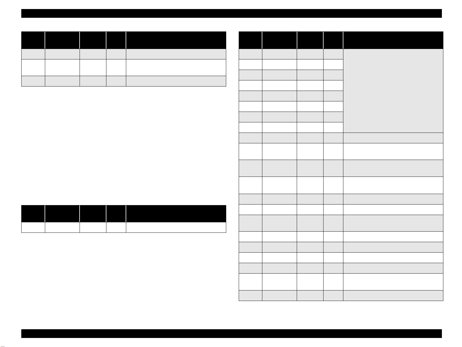
1.3.2 Printing Specification
Print method : On demand ink jet
Nozzle Configuration : monochrome 48 nozzles
: color 15 nozzles x 3 (Cyan, Magenta, Yellow)
Print direction : Bi-direction with logic seeking
Print speed & Printable columns
Character mode : Black only
Character Pitch Character Quality Printable Columns CR Speed
10CPI LQ 80 Columns 20IPS
Raster graphics mode
Horizontal
resolution
480 dpi 8.26 inch 3968 14.1 IPS Black mode
360 dpi 8.26 inch 2976 23.8 IPS 720 dpi 8.26 inch 5952 20 IPS -
1440 dpi 8.26 inch 11904 20 IPS -
Printable area Available dot CR Speed Notes
Control code* : ESC/P R4C7050 exclusive
: EPSON Remote command
Character tables* : none
ASCII 20h to 7Fh code support.
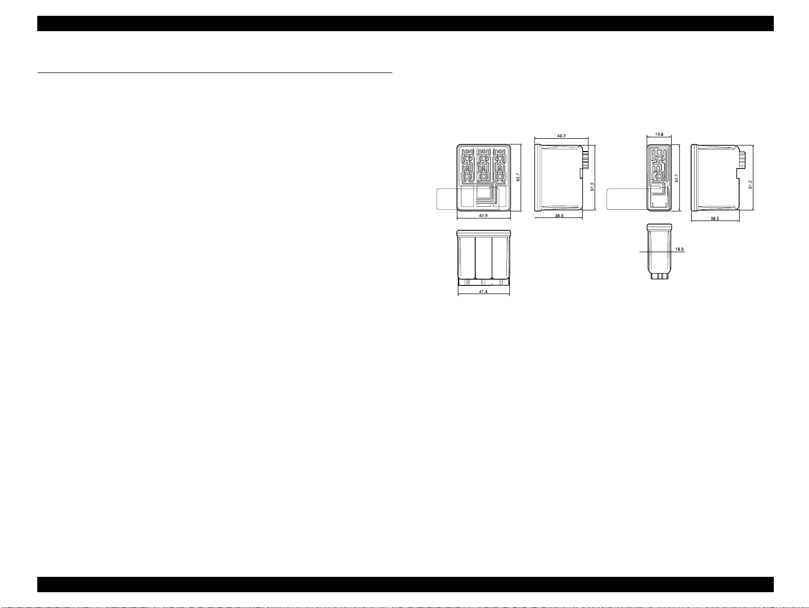
Figure 1-1. Stylus C40/C20 Dimensions
Typeface*
Bit map LQ font :EPSON Courier 10 CPI
International character sets * : None
* Do not mention to the user’s manual about control code, character tabl e, typeface and
International character sets.
PRODUCT DESCRIPTION SECIFICATIONS 10

Stylus C40UX/C40SX/C20UX/C20SX Revision B
1.3.3 Paper Feeding
Feeding method : Friction feed with ASF
Paper path : Cut-sheet ASF (Top entry)
Feed speed :
Feed condition Time Speed
10.16mm(0.4 inch) feed 110msec 92.36mm (3.64inch)/sec
Continuous feed 140msec 139.7mm (5.5inch) /sec
1.3.4 Input Data Buffer
Buffer size :12 Kbytes
1.3.5 Electrical specification
120 V version
Rated voltage : AC 120 V
Input voltage range : AC 99 - 132 V
Rated frequency range : 50 - 60 Hz
Input frequency range : 49.5 - 60.5 Hz
Rated current : 0.4A
Power consumption : Approx. 16W (ISO/IEC 10561 Letter pattern
: Approx. 4W in standby mode
: Energy Star compliant
Insulation Resistance :10 M ohms min.
(between AC line and chassis, DC 500 V)
Dielectric strength : AC 1000 V rms. 1 minute or
AC 1200 V rms. 1 second
(between AC line and chassis)
220-240 V version
Rated voltage : AC 220 - 240 V
Input voltage range : AC 198 - 264 V
Rated frequency range : 50 - 60 Hz
Input frequency range : 49.5 - 60.5 Hz
Rated current : 0.2A
Power consumption : Approx. 16W (ISO/IEC 10561 Letter pattern
: Approx. 4W in standby mode
: Energy Star compliant
Insulation Resistance :10 M ohms min.
(between AC line and chassis, DC 500 V)
Dielectric strength : AC 1500 V rms. 1 minute
(between AC line and chassis)
PRODUCT DESCRIPTION SECIFICATIONS 11
Stylus C40UX/C40SX/C20UX/C20SX Revision B
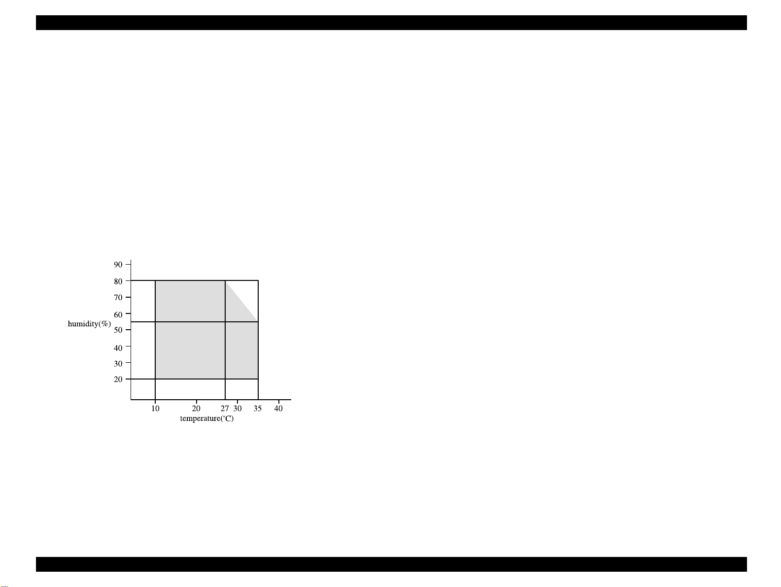
1.3.6 Envirormental Condition
Temperature : 10 to 35 ºC (operating *3 )
: -20 to 60 ºC(non-operating, *1)
1 month at 40 ºC
120 hours at 60 ºC
Humidity : 20 to 80% RH (operating, *2,*3)
: 5 to 85% RH (non-operating, *1, *2)
Resistance to shock : 1 G, within 1 ms (operating)
: 2 G, within 2 ms (non-operating, *1)
Resistance to vibration : 0.15G (operating)
: 0.50G (non-operating, *1)
*1: with shipment container
*2: without condensation
*3: Condition is as following figure.
1.3.8 Safety Approvals
120 V version :
Safety standards : UL1950 with D3
CSA C22.2 No.950 with D3
EMI : FCC part15 subpart B class B
CSA C108.8 class B
220-240 V version :
Safety standards : EN 60950(VDE)
EMI : EN 55022(CISPR Pub.22) class B
: AS/NZS 3548 class B
1.3.9 Acoustic Noise
Level : Approx. 45 dB(A) (According to ISO 7779)
1.3.10 CE Marking
220-240 V version
Low Voltage Directive 73/23/EEC : EN60950
EMC Directive 89/336/EEC : EN55022 Class B
EN61000-3-2
EN61000-3-3
EN50082-1
IEC801-2
IEC801-3
IEC801-4
Figure 1-2. Environmental Condition
1.3.7 Reliability
Total print volume : 10,000 pages (A4, Letter) or
20,000 pages (A4, Letter)
*refer to “EEPROM Address Map” on page -106
Print Head Life : 4000 million dots/nozzle
PRODUCT DESCRIPTION SECIFICATIONS 12

Stylus C40UX/C40SX/C20UX/C20SX Revision B
1.4 INTERFACE
Interface specification for each model are as the following.
Parallel Interface :EPSON Stylus C40SX .EPSON Stylus C20SX
USB Interface :EPSON Stylus C40UX .EPSON Stylus C20UX
*This printer interface as standard.
1.4.1 USB Interface
Standard : based on
“Universal Serial Bus Specifications Revision 1.1”
“Universal Serial Bus Device Class Definition for Printing Devices Version
1.1”
Bit rate : 12Mbps (Full Speed Device)
Data encording : NRZI
Adaptable connector : USB Series B
Recommended cable length : 2 meters
Connect er pin assinment and signals:
Pin No. Signal name In/Out Function description
1VCC -
2 Data bi-directional Data
Cable power. Maximum power consumption is
100mA
1.4.2 Parallel Interface (Forward Channel)
Transmission mode : 8 bit parallel, IEEE-1284 compatibility mode
Synchronization : By STROBE pulse
Handshaking : By BUSY and ACKNLG signal
Signal level : TTL compatible level
Adaptable connector : 57-30360(amphenol) or equivalent
BUSY signal is set high before setting either -ERROR
low or PE high and held high until all these signals
return to their inactive state.
BUSY signal is at high level in the following cases.
-During data entry (see Data transmission timing)
-When input data buffer is full
-During -INIT signal is at low level or during
hardware initialization
-During printer error (See -ERROR signal)
ERROR signal is at low level when the printer is in one
of the following states.
-Printer hardware error (fatal error)
-Paper-out error
-Paper-jam error
-Ink-out error
-Ink overflow error
3 +Data bi-directiona data, pull up to +3.3V via 1.5K ohm resistor
4 Ground - C able ground
Data transmission timing :
DATA
-STROBE
BUSY
-ACKNLG
PE signal is at high level during paper-out error.
Figure 1-3. USB Pin Assignment
PRODUCT DESCRIPTION INTERFACE 13

Stylus C40UX/C40SX/C20UX/C20SX Revision B
Parameter Minimum Maximum Parameter Minimum Maximum
tsetup 500 ns - treply 0 thold 500 n s - tack 500 ns 10 us
tstb 500 ns - tnbusy 0 tready 0 - tnext 0 tbusy - 500 ns
tt-out* - 120 ns * Rise and fall time of every output signals
tt-in** - 200 ns ** Rise and fall time of every input signals
***Typical time of tack is shown below.
Parallel I/F mode typical time of tack
High speed 2us
Normal speed 4usror
Signal level : TTL compatible (IEEE-1284 level 1 device)
Parameter Minimum Maximum Condition
VOH* - 5.5 V * A low logic level on the
is.
VOL* -0.5 V -
IOH* - 0.32 mA VOH = 2 .4 V
IOL* - 12 mA VOL = 0.4 V
CO - 50 pF
VIH - 2.0 V
VIL 0.8V -
IIH - 0.32 mA VIH = 2.0 V
IIL - 12 mA VIL = 0.8 V
Logic H signal is.
2.0 V or less when the
printer is powered off and
this signal is equal or
exceeding 3.0V when the
printer is powered on.
The receiver shall provide an
impedance equivalent to 7.5
K ohm to ground
Connector pin assignment and signals :
Pin No.
10 -ACKNLG 28 Out
11 BUSY 29 Out
12 PE 28 Out A high signal indicat e s paper-out error.
13 SLCT 28 Out
14 -AFXT 30 In Not used.
31 -INIT 30 In
32 -ERROR 29 Out A low signal indicates printer error condition.
36 -SLI N 30 In Not used.
18 Logic H - Out Pulled up to +5 V via 3.9 K ohm resistor.
35 +5V - Out Pulled up to +5 V via 3.3 K ohm resistor.
Signal Name
Return
1 -STROBE 19 In
2 DATA0 20 In The DATA0 through DATA7 sign als
3 DATA1 21 In
4 DATA2 22 In
5 DATA3 23 In
6 DATA4 24 In
7 DATA5 25 In
8 DATA6 26 In
9 DATA7 27 In
GND pin In/Out Functional description
The strobe pulse. Read-in of data is
performed at the falling edge of this pulse.
represent data bits 0 to 7, respectively.
Each signal is at high level when data is
logical 1 and low level when data is logical 0.
This signal is a negative pulse indicating that
the printer can again accept data.
A high signal indicates th at the printe r cannot
receive data.
Always at high level when the printer is
powered on.
The falling edge of a negative pulse or a low
signal on this line causes the printer to
initialize. Minimum 50 us pulse is necessary.
CI - 50 pF
PRODUCT DESCRIPTION INTERFACE 14
Stylus C40UX/C40SX/C20UX/C20SX Revision B
Pin No.
17 Chassis GND - - Chassis GND.
16, 33
19-30
15, 34 NC - - Not connected.
Signal Name
Return
GND - - Signal GND.
GND pin In/Out Functional description
* In/Out refers to the direction of signal flow from the printer's point of view.
1.4.3 Parallel Interface (Reverse Channel)
Transmission mode : IEEE-1284 nibble mode
Adaptable connector : See forward channel
Synchronization : Refer to the IEEE-1284 specification
Handshaking : Refer to the IEEE-1284 specification
Data trans. timing : Refer to the IEEE-1284 specification
Signal level : IEEE-1284 level 1 device
See forward channel
Connector pin assignment and signals :
Pin No. Signal Name
2 DATA0 20 In The DATA0 through DATA7 sign als
3 DATA1 21 In
4 DATA2 22 In
5 DATA3 23 In
6 DATA4 24 In
7 DATA5 25 In
8 DATA6 26 In
9 DATA7 27 In
10 PtrClk 28 Out Printer clock signal.
11
12
13
14 HostBusy 30 In Host busy signal.
PtrBusy /
DataBit-3,7
AckDataReq /
DataBit-2,6
Xflag /
DataBit-1,5
ReturnG
ND Pin
29 Out
28 Out
28 Out
In/
Out*
Function al description
represent data bits 0 to 7, respectively.
Each signal is at high level when data is
logical 1 and low level when data is logical 0.
These signals are used to transfer the 1284
extensibility request values to the printer.
Printer busy signal and reverse cha nnel
transfer data bit 3 or 7.
Acknowledge data r equ est sign al a nd r ever se
channel transfer data bit 2 or 6.
X-flag signal and reverse channel transfer
data bit 1 or 5.
Pin No. Signal Name
1 HostClk 19 In Host clock signal.
ReturnG
ND Pin
In/
Out*
Functional descrip tion
31 -INIT 30 In Not used.
32
36 1284-Active 3 0 In 1284 active signal.
18 Logic-H - Out Pulled up to +5 V via 3.9 K ohm resist or.
35 +5V - Out Pulled up to +5 V via 3.3 K ohm resistor.
17 Chassis GND - - Chassis GND.
16, 33
19-30
15, 34 NC - - Not connected.
-DataAvail /
DataBit-0,4
GND - - Signal GND.
29 Out
Data available signal and reverse channel
transfer data bit 0 or 4.
* In/Out refers to the direction of signal flow from the printer's point of view.
PRODUCT DESCRIPTION INTERFACE 15

Stylus C40UX/C40SX/C20UX/C20SX Revision B
Extensibility Request :
The printer responds affirmatively when the extensibility request values are 00H
or 04H, that mean,
00H : Request Nibble Mode Reverse Channel Transfer.
04H : Request Device ID;
Return Data Using Nibble Mode Rev Channel Transfer.
Device ID :
The printer sends following device ID string when it is requested.
When IEEE1284.4 is enabled,
[00H] [4EH]
MFG:EPSON;
CMD:ESCPL2,BDC,D4;
MDL:Stylus[SP]XXX;
CLS:PRINTER;
DES:EPSON[SP]Stylus[SP]XXX;
When IEEE1284.4 is disabled,
[00H] [4BH]
MFG:EPSON;
CMD:ESCPL2,BDC;
MDL:Stylus[SP]XXX;
CLS:PRINTER;
DES:EPSON[SP]Stylus[SP]XXX;
busy state. This slowdown is started when the rest of the input buffer becomes several
hundreds of bytes. Finally, the printer is in the busy state continuously when the input
buffer is full.
*XXX is C20 or C40
Note : (1) [00H] denotes a hexadecimal value of zero.
(2) MDL value depends on the EEPROM setting. Refer to
Appendix F.
(3) CMD value depends on the IEEE1284.4 setting, Refer to
Appendix F.
1.4.4 Prevention Hosts from Data Transfer Time-out
Generally, hosts abandon data transfer to peripherals when a peripheral is in the busy
state for dozens of seconds continuously. To prevent hosts from this kind of time-out,
the printer receives data very slowly, several bytes per minute, even if the printer is in
PRODUCT DESCRIPTION INTERFACE 16

Stylus C40UX/C40SX/C20UX/C20SX Revision B
1.4.5 IEEE1284.4 Protocol
The packet protocol described by IEEE1284.4 standard allows a device to carry on
multiple exchanges or conversations which contain data and/or control information
with another device at the sa me time across a s ingle point-t o-point link. The prot ocol i s
not, however, a device control language. It does provide basic transport-level flow
control and multiplexing services. The multiplexed logical channels are independent of
each other and blocking of one has no
effect on the others. The protocol operate over IEEE1284.
- Automatic selection
An initial state is compatible interface and starts IEEE1284.4 communication
when magic strings (IEEE 1284.4 synchronous commands) are received.
- On
An initial state is IEEE1284.4 communication and data that received it by the
time it is able to take synchronization by magic string (IEEE 1284.4
synchronous commands) is discarded.
- Off
An initial state is compatible interface and never starts IEEE1284.4
communication even if magic strings (IEEE 1284.4 synchronous commands)
are received.
Factory setting is on.(Refer to Appendix H.EEPROM Map 09h)
PRODUCT DESCRIPTION INTERFACE 17
Stylus C40UX/C40SX/C20UX/C20SX Revision B
1.5 OPERATOR CONTROLS
1.5.1 Operate Switch
Operate switch is located on the control panel.
1.5.2 Control Panel
Switches
There are 2 non-lock type push switches, and 2 LED.
Indicators
(1) Power (green)
Lights when the operate switch is "ON", and AC power is supplied.
(2) Error (red)
Lights or blinks when some error occurs to the printer.
1.5.3 Panel Functions
Panel Functions
SW Function
• Loads or Ejects the Paper(Pushing within 3seconds).
• Starts the Cleaning of head(Pushing for 3seconds)
Error Reset SW
*This function is not available in printing status.
Panel Function with Power on
• When carriage is on the Ink Cartridge ch ange position, return
carriage from Ink Cartridge change position.
• Starts the Ink Cartridge change (Pushing for 6seconds)
1.5.4 Printer Condition and Panel Status
Printer status
Power ON condition On - 10
Ink sequence Blink - 6
Ink Cartridge change mode Blink - 5
Data processing Blink - 9
Paper Out *1 - On 4
Paper jam condition*1 - On 3 3
Ink end(Black)*1 - On->On 8
Ink level low(Bl ack) - Blink->Blink 8
Ink end(Color)*1 - On->On 8
Ink level low(Color) - Blink->Blink 8
Ink end (Black and Color) - On->On 8
No Ink Cartridge (Black or Color)*1 - On 7
Maintenance request
(Ink Overflow Counter error)
Fatal error*1 Off On 1
“-”:Indicator status don’t change
“a->b”:a is a Indicator condition when carriage is on Home Position.
b is a Indicator condition in Ink exchange sequence.
Powe Error Priority
Alt blink Alt blink 2
Indicators
SW Function
Error Reset SW Starts status printings
*1 : see
PRODUCT DESCRIPTION OPERATOR CONTROLS 18

Stylus C40UX/C40SX/C20UX/C20SX Revision B
1.5.5 Printer Initialization
There are three kinds of initialization method.
(1) Power-on initialization
This printer is initialized when turning the printer power on, or printer recognized
the cold-reset command (remote RS command).
When printer is initialized, following action is performed.
(a) Initializes printer mechanism.
(b) Clears input data buffer.
(c) Clears print buffer.
(d) Sets default values.
(2) Operator initialization
This printer is initialized when printer recognized the -INIT signal (negative pulse)
of parallel interface.
When printer is initialized, following action is performed.
(a) Cap the print head.
(b) Eject a paper.
(c) Clears input data buffer.
(d) Clears print buffer.
(e) Sets default values.
(3) Software initialization
The ESC @ command also initializes the printer.
When printer is initialized, following action is performed.
1.5.6 Errors
Ink out
When the printer runs out the most part of the ink of any one color, it warns ink-
low and keeps printing.When the printer runs out the whole ink of any one color, it
stops printing and indicates ink-out error. User is requested to install a new inkcartridge in this state.
Paper out
When printer fails to load a sheet, it goes paper out error.
Paper jam
When printer fails to eject a sheet, it goes paper jam error.
No ink-cartridge
When printer detects that ink-cartridge comes off , it goes this error mode.
Maintenance request
When the total quantity of ink wasted through the cleanings and flushing is
reaches to the limit, printer indicates this error and stops. The absorber in the
printer enclosure is needed to be replaced with new one by a service person.
Fatal errors
Carriage control error.
* panel status is described on section1.4.4.
(a) Clears print buffer.
(b) Sets default values.
(4) Power-on initialization except I/F
The printer recognized the IEEE 1284.4 “rs” command.
When printer is initialized, following action is performed.
(a) Initializes printer mechanism.
(b) Clears input data buffer.
(c) Clears print buffer.
(d) Sets default values except I/F.
PRODUCT DESCRIPTION OPERATOR CONTROLS 19

Stylus C40UX/C40SX/C20UX/C20SX Revision B
1.6 PAPER
1.6.1 Paper Handling
Do not perform reverse feed more than 0 mm(0”).
1.6.2 Paper Specification
Cut Sheet
Size : A4 (Width 210 mm(8.3") x Length 297 mm(11.7"))
: Letter (Width 215.9 mm(8.5") x Length 279.4 mm(11.0"))
: B5 (Width 182 mm(7.2") x Length 257 mm(10.1"))
: Legal (Width 215.9 mm(8.5") x Length 355.6 mm(14.0"))
: Half Letter (Width 139.7 mm(5.5") x Length 215.9 mm(8.5"))
: Exclusive (Width 184.2 mm(7.5") x Length 266.7 mm(10"))
: A5 (Width 148 mm(5.8") x Length 210 mm(8.3"))
: A6 (Width 105 mm(4.1") x Length 210 mm(8.3"))
Thickness : 0.08 mm(0.003") - 0.11 mm(0.004")
Weight : 64 g/m 2 (17 lb.55Kg) - 90 g/m 2 (24 lb.78Kg)
Quality : Exclusive paper, Bond paper, PPC
Envelope
Size : No.10 Width 241 mm(9 1/2") x Length 104.8 mm(4 1/8")
: DL Width 220 mm(8.7") x Length 110 mm(4.3")
: C6 Width 162 mm(6.4”) x Length 114 mm(4.5”)
: Envelope220*132 Width 220 mm(8.7”) x Length 132 mm(5.2”)
: Japanese CHOUKEI 3 Width 120 mm x Length 235 mm *
: Japanese CHOUKEI 4 Width 90 mm x Length 205 mm *
: Japanese YOUKEI 1 Width 120 mm x Length 176 mm *
: Japanese YOUKEI 2 Width 114 mm x Length 162 mm *
: Japanese YOUKEI 3 Width 98 mm x Length 148 mm *
: Japanese YOUKEI 4 Width 105 mm x Length 235 mm *
* except for glue.
Thickness : N/A
Weight :#10,DL,C6 45 g/m 2 (12 lb.) - 75 g/m 2 (20 lb.)
: CHOUKEI 50 g/m 2 (43Kg) - 70 g/m 2 (60Kg)
: YOUKEI 50 g/m 2 (43Kg) - 100 g/m 2 (86Kg)
Quality : #10,DL,C6 Bond paper, Plain paper, Air mail
: CHOUKEI4,3 Kraft, new Kent paper
: YOUKEI1,2,3,4 Kraft, new Kent paper
* Envelope printing is only available at normal temperature.
* Keep the longer side of the envelope horizontally at setting.
Exclusive paper
Quality : EPSON Exclusive paper
* Transparency printing is only available at normal temperature.
< Photo Quality Ink Jet Paper >
Size :A4 (210mm x 297mm)
:A6 (105mm x 148mm)
:B5 (182mm x 257mm)
:Letter (216mm x 279mm)
:Legal (216mm x 356mm)
:5” x 8” (127mm x 203mm)
:8” x 10” (203mm x 254mm)
:Post Card (100mm x 148mm)
Thickness : 0.13 mm(0.005")
Weight : 98 g/m 2 (26 lb.84Kg)
<360 dpi Ink Jet Paper >
Size : A4 (210mm x 297mm)
: Letter (216mm x 279mm)
Thickness : 0.11 mm(0.004")
Weight : 89 g/m 2 (24 lb.78Kg)
<RC paper>
Size : A4 (210mm x 297mm)
: Letter (216mm x 279mm)
Thickness : <T.B.D.>
Weight : <T.B.D.>
<Ink Jet Transparencies>
Size : A4 (210mm x 297mm)
: Letter (216mm x 279mm)
Thickness 0.13 mm(0.005")
Weight : N/A
PRODUCT DESCRIPTION PAPER 20

Stylus C40UX/C40SX/C20UX/C20SX Revision B
< Photo Quality Glossy Film >
Size : A4 (210mm x 297mm)
: A6 (105mm x 148mm)
: Letter (216mm x 279mm)
Thickness : 0.13 mm(0.005")
Weight : N/A
<Matte paper Heavy weight>
Size : A4 (210mm x 297mm)
: Letter (216mm x 279mm)
Thickness : 0.23 mm(0.009")
Weight : 167 g/m 2 (44 lb.143Kg)
< Iron-on Cool Peel Transfer Paper >
Size : A4 (210mm x 297mm)
: Letter (216mm x 279mm)
Thickness : 0.18 mm(0.007")
Weight : 124 g/m 2 (33 lb.107Kg)
*Base paper weight.
1.6.3 Printing Area
Cut Sheet
<Ink jet paper>
Size : A4 (210mm x 297mm)
Thickness : 0.11 mm(0.004")
Weight : 80 g/m 2 (21 lb.45Kg)
Figure 1-4. Printable Area for Cut Sheet
PRODUCT DESCRIPTION PAPER 21

Stylus C40UX/C40SX/C20UX/C20SX Revision B
Raster Graphics mode
Paper size
A4
Letter
B5
Lega
Statement
Executive
PW
(Paper
width)
(typ.)
210mm
(8.3”)
216mm
(8.5”)
182mm
(7.2”)
216mm
(8.5”)
139.7mm
(5.5”)
190.5mm
(7.5”)
PL
(Paper
length)
(typ.)
297mm
(11.7”)
279mm
(11.0”)
257mm
(10.1”)
356mm
(14.0”)
215.9mm
(8.5”)
254mm
(10”)
LM
(left
margin)
(min.)
3mm
(0.12”)
3mm
(0.12”)
3mm
(0.12”)
3mm
(0.12”)
3mm
(0.12”)
3mm
(0.12”)
RM
(Right
margin)
(min.)
3mm
(0.12”)
3mm
(0.12”)
3mm
(0.12”)
3mm
(0.12”)
3mm
(0.12”)
3mm
(0.12”)
TM
(Top
margin)
(min.)
3mm
(0.12”)
3mm
(0.12”)
3mm
(0.12”)
3mm
(0.12”)
3mm
(0.12”)
3mm
(0.12”)
Black BM
(Bottom margin)
(min.)
14mm (0.54”)
/3mm (0.12”)
14mm (0.54”)
/3mm (0.12”)
14mm (0.54”)
/3mm (0.12”)
14mm (0.54”)
/3mm (0.12”)
14mm (0.54”)
/3mm (0.12”)
14mm (0.54”)
/3mm (0.12”)
Color BM
(Bottom margin)
(min.)
21mm (0.83”)
/3mm (0.12”)
21mm (0.83”)
/3mm (0.12”)
21mm (0.83”)
/3mm (0.12”)
21mm (0.83”)
/3mm (0.12”)
21mm (0.83”)
/3mm (0.12”)
21mm (0.83”)
/3mm (0.12”)
* Bottom margin is expanded to 3mm when paper dimension is defined by using
command(ESC (S), otherwise it is not expanded (Black,14mm Color 21mm). Refer to
Appendix C.
** Print quality may decline in the expanded areas(For 3 mm to 14 mm (Color 21mm)
of the printing areas).
Paper
size
#10
Envelope
LM(Left
margin)
(min.)
28mm(1.10
”)
Figure 1-5. Printable Area for Envelopes
RM(Right
margin)
(min.)
3mm(0.12”) 3mm(0.12”)
TM(Top
margin)
(min.)
Black BM
(Bottom margin )
(min.)
14mm(0.54”0
/3mm(0.12”)*
Color BM
(Bottom margin)
(min.)
21mm(0.83”)
/3mm(0.12”)*
DL 7mm(0.28”) 3mm(0.12”) 3mm(0.12”)
C6 3mm(0.12”) 3mm(0.12”) 3mm(0.12”)
14mm(0.54”0
/3mm(0.12”)*
14mm(0.54”0
/3mm(0.12”)*
21mm(0.83”)
/3mm(0.12”)*
21mm(0.83”)
/3mm(0.12”)*
* Bottom margin is expanded to 3mm when paper dimension is defined by using
command ESC (S), otherwise it is not expanded (Black,14mm Color 21mm). Refer to
Appendix C .
** Print quality may decline in the expanded areas(For 3 mm to 14 mm (Color 21mm)
of the printing areas).
PRODUCT DESCRIPTION PAPER 22
Stylus C40UX/C40SX/C20UX/C20SX Revision B
1.7 INK CARTRIDGE
1.7.1 Black Ink Cartridge
Type : Exclusive cartridge
Color : Black
Print capacity : 270 pages / A4 (ISO/IEC10561 Letter Pattern at 360 dpi)
Ink life : 2 years from production date
Storage temperature : -20°C - 40°C (Storage, within a month at 40°C)
: -30°C - 40°C (Packing storage, within a month at 40°C)
: -30°C - 60°C (Transit, within 120 hours at 60°C and
within a month at 40)
Dimension : 19.8 mm(W) x 52.7 mm(D) x 38.5 mm(H)
1.7.2 Color Ink Cartridge
Type : Exclusive cartridge
Color : Magenta, Cyan, Yellow
Print capacity : 150 pages /A4 (360 dpi, 5% duty each color)
Ink life : 2 years from production date
Storage temperature : -20°C - 40°C (Storage, within a month at 40°C)
: -30°C - 40°C (Packing storage, within a month at 40°C)
: -30°C - 60°C (Transit, within 120 hours at 60°C and
within a month at 40)
Dimension : 42.9 mm(W) x 52.7 mm(D) x 38.5 mm(H)
* Ink cartridge can not re-fill, only ink cartridge is prepared for article of consumption.
* Do not use the ink cartridge which was passed away the ink life.
* Ink will be frozen under -18 to -21 o C environment, however it will be usable after
placing it more than 3 hours at room temperature. mm (0.12”) *
Ink cartridge (color) Ink cartridge (black)
PRODUCT DESCRIPTION INK CARTRIDGE 23

OPERATING PRINCIPLES
CHAPTER
2
Stylus C40UX/C40SX/C20UX/C20SX Revision B
2.1 Overview
Paper Eject Roller
This section describes the operating principles of the printer mechanism and electrical
circuit boards. The Sty lus C40UX/C40SX/C20UX/C20SX has on ly the following two
circuit boards:
Main board: C413 MAIN/MAIN-B
Power supply board: C417 PSB/PSE
PF Motor
Star Wheel Roller
PF Roller
CR Timing belt
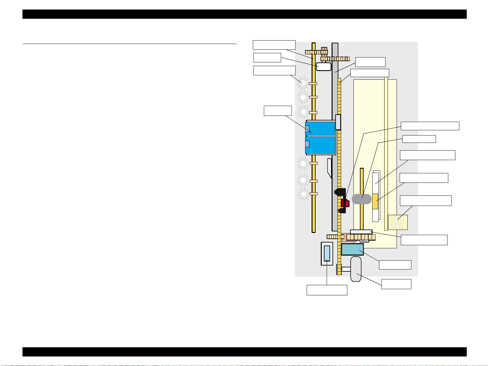
2.1.1 Printer Mechanism
The printer mechanism for Stylus C40 UX /C40 SX/ C2 0UX /C20SX is designed newly.
But, the basic component of the printer mechanism is same as previous product.
This printer consists of Print Head, Carriage Mechanism, Paper Feeding Mechanism,
Paper Loading Mechanism, Ink System (Pump Mechanism, Cap Mechanism, and
Carriage Lock Mechanism).
Like other EPSON ink jet printers, the Stylus C40UX/C40SX/C20UX/C20SX is
equipped with two stepping motors; one for ASF, Paper feeding/ Pump mechanism,
and one for CR mechanism. ASF unit uses rear entry fr ont eject s ystem. Th is ASF unit
is also designed newly and single LD roller loads the paper to the printer mechanism.
For cap assembly, Stylus C40UX/C40SX/C20UX/C20SX uses valveless mechanism;
new design for this model.
CR unit
HP/PE/IC Sensor sensor
LD Roller
Paper feed back plate
Paper separation pad
ASF Hopper Spring
Clutch mechanism
Pump unit
CR Motor
Cap Assembly
Figure 2-1. Printer Mechanism block diagram
Operating Principles Overview 25

Stylus C40UX/C40SX/C20UX/C20SX Revision B
2.1.2 Printhead
The printhead uses a new developed U-CHIPS head and Stylus C40UX/C40SX/
C20UX/C20SX can perform multiple shot printing and variable printing. Printhead
nozzle configuration is as follows.
48 nozzles x 1 row: Black (nozzle pitch of the row: 1/120 inch)
45 nozzles x 1 row: Color (nozzle pitch of the row: 1/120 inch)
In the one row for the color, 15 nozzles are assigned for each yellow,
magenta, cyan color)
The basic operating principles of the printhead, which plays a major role in printing,
are the same as previous models; on-demand method which uses PZT (Piezo Electric
Element). In order to uniform the amount of ejecting ink, the printhead has its own
head ID (6 digits for this printhead) which adjust PZT voltage drive features.
The printer read the head ID form EEPROM and generates appropriate PZT drive
voltage to prevent amount of ink from varying by printheads.
Following explains printhead basic components.
PZT
PZT is an abbreviation of Piezo Electric Element. Certain amount of voltage
expands and contracts PTZ. The dri ve wave generated o n MAIN board driv es PZT
and PZT pushes the top cavity which has ink stored to disc harge the ink fr om each
nozzle on the nozzle plate.
Nozzle Plate
Head Driver Board
Ink Cartridge
PZT
Needle
Filter
Cavity
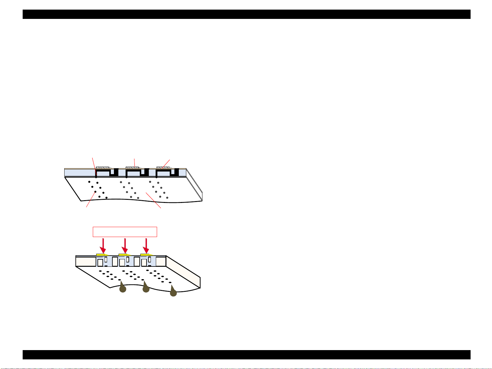
Figure 2-2. Printhead Sectional Drawing
Ink Cavity
The ink absorbed from the ink cartridge goes through the filter and then is stored
temporarily in this tank called “cavity” until PZT is driven.
Nozzle Plate
The board with nozzle holes on the printhead surface is called Nozzle Plate.
Filter
When the ink cartridge is installed, if any dirt or dust around th e cartridge needle is
absorbed into the head, there is a great possibility of causing nozzle clog and
disturbance of ink flow, and finally causing alignment failure and dot missing. To
prevent this problem, a filter is set below the cartridge needle, wh ere ink is filtered.
Operating Principles Overview 26
Stylus C40UX/C40SX/C20UX/C20SX Revision B
2.1.2.1 Printing Process
This section explains the process in which the printheads of On- Demand inkj et printers
eject ink from each nozzle.
1. Normal State:
When no printing signal is sent from PC, or no PZT drive voltage is applied, PZT
does not change shape, therefore PZT does not squeeze the cavity. Ink pressure
inside the cavity is kept normal. (Refer to Figure 2-3.)
2) Ejecting State:
When the print signal is output from the C413MAIN/B board, IC (Nozzle
Selector) located on the printhead unit latches data once by 1-byte unit. An
appropriate PZT latched by the nozzle selector is pushed into the cavity by the
common voltage applied from the main board. By this operation, ink stored in the
cavity spurts out from nozzles.(Refer to Figure 2.1.2.2.)
Ink Path
Nozzle
PZT
Ink Cavity
Nozzle plate
2.1.2.2 Printing Method
For print dot system, Stylus C40UX/C40SX/C20UX/C20SX has the following two
kinds of printing modes.
Multiple shot printing
Variable dot printing
The above two printing modes are automatically selected depending on the media and
the resolution setting of the printer driver. The following explains each printing mode.
Multiple shot printing
This printing mode is developed to improve the print quality on plain paper or
transparencies in low resolution. The multiple shot printing mode uses normal dot
and the number of dot shots varies from 1 shot to maximum 4 shots depending on
the print data to enable sharp image output even in a low resolution.
Variable dot printing
This printing mode is developed to improve the print quality on exclusive paper.
This mode is basically the same as variable dot printing mode used on other
products /; micro dot, middle dot, and large dot compose this mode. Print dot size
varies according to print data and this mode enables even sharper im age ou tput o n
exclusive paper.
PZT drive voltage
Figure 2-3. Printhead printing process
Operating Principles Overview 27
Stylus C40UX/C40SX/C20UX/C20SX Revision B
2.1.3 Carriage Mechanism
The carriage mechanism consists of Carriage motor (CR motor), Carriage unit
(including printhead), CR timing belt, CR guide shaft, CR guide frame, CR home &
I/C detector (HP/PE/IC sensor) etc. The carriage mechanism moves the carriage back
and forth according to the dr ive from the carriage motor. Th e following steppi ng motor
is mounted to drive CR mechanism. (See the table below.)
Table 2-1. Carriage Motor Specification
Items Specifications
Type 4-Phase/ 48-Pole PM Stepping motor
Drive Voltage +42 V +/ - 5% (DRV IC voltage)
Coil Resistance 10.8 Ω +/ - 10% (per phase at 25 degree)
Inductance 15 mH +/ - 20%(1KH 1VmA)
Drive Method Bi-Polar drive
Driver IC XC901503FNR2
The drive from CR motor is transferred to the CR unit via CR timing belt. And the CR
home position is detected with the HP/PE/IC sensor. This sensor is available as CR HP
detector only in the HP (home position) detection sequence & pump operation
sequence. (not available in the paper feeding sequ ence fo r the C R HP detector becaus e
it is used for only PE sensor during the paper feeding sequence.) Moreover, unlike the
previous products, this printer dose not have the PG adjustment mechanism.
CR home position is detected with the HP/PE/IC sensor and the d etection plate molded
in the CR unit as following figure. When the CR home position is detected with this
sensor, HIGH signal is output to the CPU.
HP/IC detection Lever
CR HP dete ction plate
Right side view
CR HP detection plate
HP/IC detection
Lever
Low signal
High signal
Figure 2-5. CR home position
Unlike the previous products, I/C detection sensor is not built in the CR unit.
The I/C is detected with the HP/PE/IC sensor and the detection plate mo lded on the I/C
cover as following figure. The I/C installation condition is monitored only when the
CR unit moves to the I/C detection position (HP detection sequence). So, this sensor
function is not available in the paper feeding sequence. When the I/C is not installed
into the CR unit, HIGH signal is output to the CPU.
HP/IC detection Lever
Right side view
I/C detection plate
HP/PE/ICSensor
CR Motor
High signal
I/C detection plate
HP/IC detection
Lever
Low signal High signal
Figure 2-6. I/C detection position
CR unit
CR Timing belt
Figure 2-4. Carriage Mechanism (Top view)
Operating Principles Overview 28

Stylus C40UX/C40SX/C20UX/C20SX Revision B
Also, when replacing ink use this lever to confirm whether the cover cartridge is open
or closed.
There are separate replacement positions for replacing the Black and Color ink
cartridges. If the cover cartridge is open, the I/C detection plate makes contact with the
HP/IC detection lever, causing the HP/IC sensor to detect a high signal.
HP/IC detection Lever
I/C detection plate
Right side view
High signal
I/C detection plate
HP/IC
detection Lever
Low signal
Figure 2-7. I/C change position
If a High signal is detected even once, it is regarded as if that ink cartridge was
replaced and the cleaning and ink counters are cleared.
If the High signal is not detected even once, the cleaning and ink counter are not
cleared.
If both the ink cartridges have not been set before carrying out initial filling, the
carriage moves to the position where both ink cartridges can be set, but checking if the
cartridge is open or closed is not done.
If one of the ink cartridges has not been set, the carriage moves to the replacement
position of the ink cartridge that is not set due to one time prevention of the set ink
cartridge.
Operating Principles Overview 29

Stylus C40UX/C40SX/C20UX/C20SX Revision B
2.1.4 Paper Feeding Mechanism
The paper feeding mechanism consists of Paper feed motor (PF motor), PF roller,
Paper eject roller, Star wheel roller, and so on. The paper feeding mechanism feeds
paper loaded from ASF using the PF roller and Paper Eject Roller & Star wheel roller.
For this mechanism, the PF motor mentioned in the right Table 2-2 is used on this
product.
The drive of the PF motor is transfer to the PF roller and the Paper Eject Roller as
following Figure 2-8. Following shows you how to transfer the PF motor drive to the
PF roller and the Paper Eject Roller.
PF motor drive transmission path
PF Motor Pini on Gear (CW)
→
Spur Gear 60 (PF roller)(CCW)
→
Spur Gear 60 (PF roller)(CCW)
Table 2-2.
Item Description
Motor type 4-Phase/ 48-Pole PM Stepping motor
Drive voltage +42 V +/ - 5% (DRV IC voltage)
Coil Resistance 10 Ω +/ - 10% (per phase)
Inductance 10.5 mH +/ - 20%(1kH 1Vrms)
Driving method Bi-Polar drive
Driver IC XC901503FNR2
Change Lever
PF Motor Specifications
Spur Gear 35.2
Combination
Gear 16, 32
PF roller
Spur Gear 10. 8
Spur Gear 18. 28
Spur Gear 25.6
Spur Gear 27. 2
Figure 2-8. Paper Feeding Mechanism
Paper loaded from ASF is advanced by the following roller.
Paper feed roller & Paper guide roller (assembled on the Top Frame)
eject roller & Star wheel roller (assembled on the Paper eject frame).
→ Paper
Operating Principles Overview 30

Stylus C40UX/C40SX/C20UX/C20SX Revision B
Additionally, the top & end of the paper is detected with the HP/PE/IC sensor.
In case the PE sensor dose not detect the paper in the paper loading sequence, the
printer detects the “Paper out error”. If the paper is detected after complete the paper
eject sequence, the printer detects the “Paper jam error”.
2.1.5 Paper Loading Mechanism (ASF Unit)
The Paper loading mechanism is positioned at the printer rear. The Paper loading
mechanism loads paper at the ASF unit and feeds paper to the PF roller.
This ASF unit was designed newly for this product and consists of LD roller, Pad
holder (Paper return plate), ASF Frame, Hopper, and so on.
For the major feature of this ASF unit, ASF HP sensor is not used and the single LD
roller is built in the ASF unit.
Drive sent from the PF motor is always transmitted to the ASF unit side. But, the
Change lever and the Clutch mechanism switch ON/OFF the PF motor drive to the LD
roller with the motor rotational direction.
Drive from the PF motor is transmitted to the ASF unit as described below:
Switch the PF motor drive to ASF unit side
→
PF Motor Pinion Gear (CCW)
→
10.8 (CW)
Gear 25.6 (CCW)
lock position
Combination Gear
→
Change Laver Rotates (CCW)
Following Figure 2-9 shows you the switching path for PF motor drive to ASF unit
side.
Change Lever
Spur Gear 60 (PF Roller) (CW) → Spur Gear
18, 28 (CCW) → Spur Gear 27.2 (CW) → Spur
→
Release the Clutch mechanism
Spur Gear 35. 2
Combination
Gear 35. 2
Spur Gear 10. 8
Combination Gear 18, 28
Spur Gear 25. 6
Spur Gear 27. 2
Figure 2-9. Switch the PF motor drive to ASF unit side
Operating Principles Overview 31

Stylus C40UX/C40SX/C20UX/C20SX Revision B
Transfer the PF motor drive to LD roller
PF Motor Pini on Gear (CW)
(CCW)
25.6 (CW) →
Spur Gear 35.2 (CW) (include the clutch mechanism) →
→
Combination Gear 18, 28 (CW) →
Change Laver rotates (CW) → Combination Gear 16, 32 (CCW) →
→ Spur Gear 60 (PF Roller) (CCW) →
Spur Gear
27.2 (CCW)
LD Roller (CW)
Spur Gear
→ Spur Gear
10.8
Following Figure 2-9 shows the PF motor drive transmission path to the LD roller unit
built in the ASF unit. The LD roller is assembled on the same shaft that the Spur gear
35.2 is assembled.
Figure 2-10. PF motor drive transmission path
When the PF motor torque is switched to the ASF unit side by the clutch mechanism,
the function of the ASF mechanism varies depending on the rotational direction of the
PF motor, as shown in the table below.
Table 2-3. ASF unit function & PF Motor rotational direction
Change Leve r
Spur Gear 10, 8
Combination Gear 18, 28
Spur Gear 27. 2
Spur Gear 35. 2
Combination
Gear 35. 2
Spur Gear 25. 6
Clutch Mechanism
Unlike the previous products, this product dose not have a ASF HP sensor.
Instead of the ASF HP sensor, Change lever and the Clutch mechanism are used to
detect the ASF home position. Following figures describe the mechanism.
Directions Corresponding Functions
Clockwise (*1)
Counterclockwise (*1)
• Picks up and loads paper
• Release the DE lever & Clutch mech anism
(*1): The PF Motor rotational direction = seen from the right side of the printer.
Operating Principles Overview 32

Stylus C40UX/C40SX/C20UX/C20SX Revision B
NOTE:
The Clutch gear is molded on
the back side of the Spur gear
35.2 such as Combination gear.
Spur gear 35.2
Clutch lever
Step1
Change Lever
Figure 2-11. Disengage & Clutch mechanism
The Clutch mechanism transmits the PF motor drive to the LD roller shaft only when
the Clutch gear rotates CW direction after the Change lever releases the Clut ch lever. If
the Clutch gear rotates CCW direction, the PF motor drive is not transmitted to the LD
roller. This is due to the combination of the shape of the Clutch gear and the Clutch
lock tooth su ch as described on the figure.
1. When the paper is advanced with the PF roller, the Change lever is set on the
Clutch lever and the Clutch is pushed down as above Step1’s figure. As the
result, the Clutch gear (*1) is released from the Cluck lock tooth and the drive
from the PF motor is not transmitted to the LD roller shaft.
Clutch gear
Clutch
Step2
Tension spring 0.143
Clutch lock tooth
Step3
LD roller shaft
Paper Return Plate (Pad holder)
Unlike the previous products, The Paper return plate is built in the ASF frame instead
of the Paper return lever. The Paper separation pad is also stacked on the plate.
It works with the spring force of the Torsion sprin g 26 (mo unted in the ASF f rame) as
following figure.
LD roller
Paper Return
Plate
Hopper
2. When the PF pinion gear rotates CCW direction in the above Step2’s figure, the
Change lever moves to the left direction with the CCW rotation of Spur gear 25.6.
The Clutch turns back to the engagement position by the tension force of the
Tension spring 0.143 and the Cl utch gear is engaged with the Clutch lock tooth as
above Step2’s center figure.
ASF frame
Torsion spring 26
Figure 2-12. Paper Return Plate
Compression spring 2.11
3. When the PF pinion gear rotates CW direction in the above Step3’s figure, the
Change lever moves to the right direction with the CW rotation of the Spur gear
25.6. And the drive from the PF motor is transmitted to the LD roller shaft via
Clutch gear and Clutch lock tooth.
4. The LD roller shaft rotates about 360 degree and the Ch ange lever p ush the Clutch
lever and the PF motor drive is interrupted. This position is the ASF home
position.
The Paper return plate is set to return the paper to the paper stand-by position in the
ASF unit when the ASF unit is in the standby mode. When the paper is fed with the
LD roller, the Paper return plate is stored in the ASF frame by the LD roller.
Following figures show you the ASF paper loading sequence and the operation of the
each mechanism.
Operating Principles Overview 33

Stylus C40UX/C40SX/C20UX/C20SX Revision B
.
When the paper is advanced with
the PF roller, Change lever push
down the Clutch lever as right
figure and the Clutch lock tooth is
disengaged from the Clutch gear.
As the result, the drive from the PF
motor is interrupted and the LD
roller dose not rotate.
This position is the ASF home
position.
The Paper return plate is set to
avoid that the paper is slipped
down from the paper set position.
The PF motor pinion gear rotates
CW direction and the drive from the
PF motor is transmitted to the ASF
LD roller shaft through the Clutch
lock tooth and the Clutch gear.
The ASF hopper release lever rotates
with the ASF LD roller and release
the ASF Hopper. The ASF hopper is
pushed with the Compression spring
2.11 and the paper is picked up with
the ASF LD roller.
LD roller shaft
Paper return plate
PF roller CCW
rotation
ASF Hopper
release lever
LD roller
Clutch lever
Step 1
Change lever
Step 3
Clutch gear
Clutch lock tooth
Clutch
LD roller shaft
Hopper
Compression
spring 2.11
Printer front si de
PF roller CW
rotation
ASF Frame
Step 2
Tension spring 0.143
Step 4
Paper return plate
When the paper is loaded (pick up) from
the ASF unit, the Change lever moves to
the printer front side with the CCW
rotation of the PF motor pinion gear and
releases the Clutch lever. As the result,
the Clutch turns back to the engagement
position by the tension force of the
Tension spring 0.143.
And the Clutch lock tooth is engaged
with the Clutch gear as right figure.
The ASF LD roller rotates CW direction
moreover and the Paper return plate is
stored under the ASF frame.
The paper is advanced up to the PF roller
and the ASF LD roller & the clutch rotate
to the “Step1” position. The Clutch lever
is locked with the Change lever.
The drive from the PF motor is
interrupted and the drive is transmitted to
the PF roller side.
PF roller CCW
rotation
ASF hopper
release lever
PF roller CCW
rotation
Figure 2-13. ASF Paper Loading Sequence
Operating Principles Overview 34

Stylus C40UX/C40SX/C20UX/C20SX Revision B
2.1.6 Ink System Mechanism
Ink system mechanism consists of pump unit (include the CR lock lever) and capping
mechanism. Ink system mechanism drives the pump unit that presses cap to the
printhead and ejects ink from ink cartridge, head cavity and cap to the waste ink pad.
2.1.6.1 Pump Unit & Wiper mechanism
The pump unit is driven by PF motor. PF motor drive is always transmitted to the paper
feeding mechanism and pump unit through the following gears. Refer to the Figure
2-15.
PF Motor Pinion Gear (CCW)
Combination Gear 18, 28 (CCW) → Spur Gear 27.2 (CW)(Pump unit)
→
Spur Gear 60 (PF Roller)(CW) → Spur Gear 10.8(CW)
→
Pump unit
Table 2-4. PF motor rotational direction & Ink System Mechanism
Directions Functions
Counterclockwise (*1)
• Absorbs ink by the pump unit
• Set the CR lock lever
(*1): The PF Motor rotational direction = seen from the right side of the printer.
Following figure shows the overview of the pump mechanism operation.
Figure 2-14. Pump mechanism
Spur Gear 10. 8
Cap unit
Pump unit
Combination Gear 18, 28
Spur Gear 27. 2
Figure 2-15. PF motor drive transmission path to the Pump unit
Operating Principles Overview 35

Stylus C40UX/C40SX/C20UX/C20SX Revision B
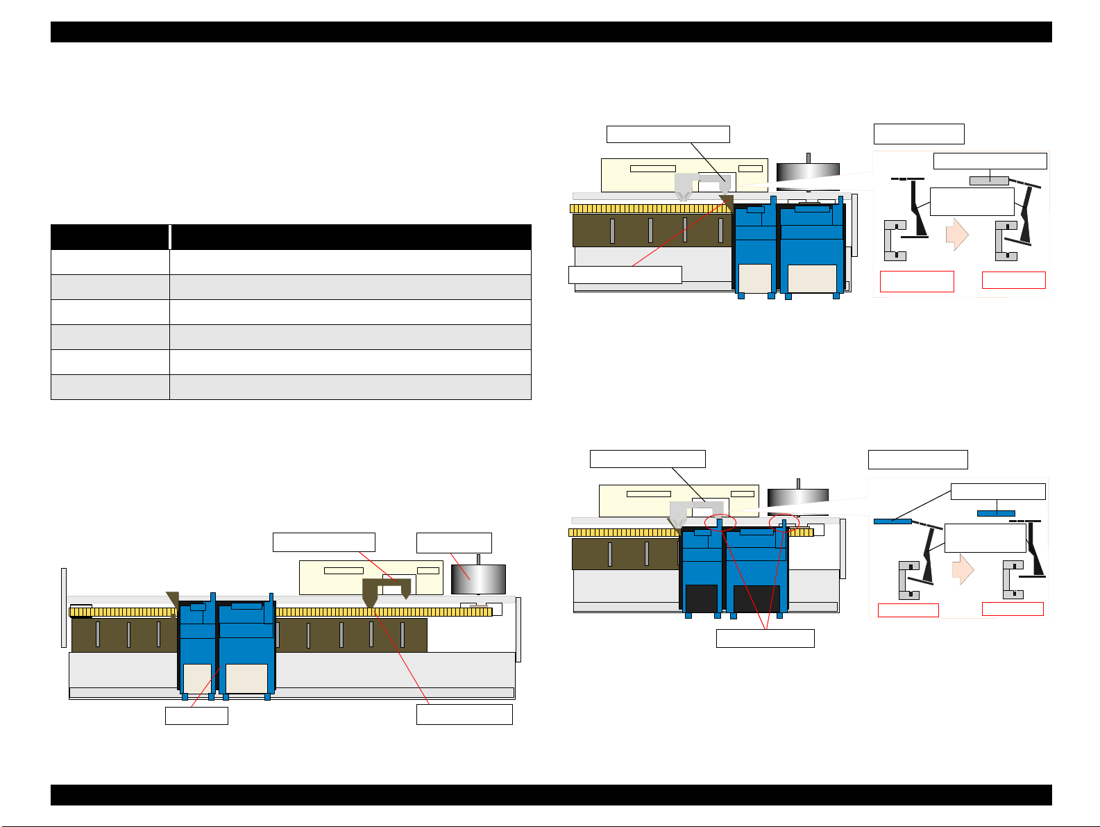
2.1.6.2 Capping Mechanism
The capping mechanism covers the p rintheads with the cap holder to p revent the nozzle
from increasing viscosity when the printer is in stand-by mode or when the printer is
off. This product has valveless cap system. Air valve function used for the previous
models pumps and ejects ink only inside the cap by absorbing ink with the valve open.
By opening the Air valve, the negative pressure is decreased and only the ink inside the
cap is ejected. (the ink is not absorbed from Ink cartridge or head cavity.)
But, valveless cap system, this operation is done out side of the capping area.
The CR moves to left side of the Cap assembly and the pump abs orbs the in k inside the
cap.
Viewed from front side
CR unit
Slider cap
Printhead
Cap
Waste Ink tube
Figure 2-16. Cap Mechanism
Slide up
3. If the carriage moves to the left side, spring forces tends to force the cap back to its
original position, but it stops at the wiping position due to the lever lock slider.
(Refer to Figure 2-17. Wiping Position)
4. When the carriage moves to the left side, the head surface and wiper makes contact
and wiping is performed. (Refer to Figure 2-17. Wiping Position)
5. Even when wiping is completed, the carriage moves further to the left side and
when the hook on the carriage’s right side hits the lever lock slider lever, the lever
lock slider’s hook is released. (Refer to Figure 2-17. Wiper Set Release)
Carriage unit
The carriage
pushes the lever.
Right side from
capping position
Hook
Figure 2-17. Wiper Set Position
Print head
Wiper
Figure 2-17. Wiping Position
Carriage unit
Print head
Hook
The hook is
released.
Also, unlike previous models, the cap unit is newly designed for this model as follows.
2.1.6.2.1 Wiper with the cap unit
Wiping control is carried out by the procedure shown below.
1. The carriage is moved to the wiper set position. (Refer to Figure 2-17. Wiper Set
Position)
2. When the carriage moves to the wiper set position, the hook on the lever lock
slider engages, locking the lever lock slider. (Refer to Figure 2-17. Wiper Set
Position)
Wiper
Figure 2-17. Wiping
Print head
Figure 2-17. Wiper Release
Operating Principles Overview 36

Stylus C40UX/C40SX/C20UX/C20SX Revision B
2.1.6.2.2 Non porous pad in cap
Due to this, the cap is newly designed as follows.
Stylus C40/C20
seal rubber
ink eject hole
Stylus COLOR 480
porous pad
Figure 2-18. non porous pad in cap (Stylus C40/C20)
The cap unit used for the previous models has the porous pad to keep the moisture in
the cap and prevent that the air bubble occurs in CL sequence.
To get the same effects on new cap unit without the porous pad.
For keep the moisture in the cap
The diameter of the ink eject hole is smaller than that of Stylus COLOR 480
For prevent that the air bubble occurs in CL sequence
The cap is modified so that ink flows to ink eject hole with air bubble in CL
sequence.
Operating Principles Overview 37

Stylus C40UX/C40SX/C20UX/C20SX Revision B
2.1.7 Ink Sequence
Initial ink charge
After the product is purchased and the printer is turned on for the first time, the
printer must be performed the initial ink charge and charges ink inside the head
cavity. When the initial ink charge is completed properly, the printer releases the
flag inside the EEPROM and no initial ink charge will be performed next time the
power is turned on. Stylus C40UX/C40SX/C20UX/C20SX takes 70 seconds to
complete the initial ink charge sequence and consume about 1/4 of the brand-new
black ink cartridge. If the power is turned off during initial filling, CL1 is
performed when the power is turned on the next time.
Manual Cleaning
Stylus C40UX/C40SX/C20UX/C20SX provides three type of manual cleaning to
clean air bubbled or clogged ink with viscosity or foreign substances.
The following manual CL sequences can be executed by the utility included in the
printer driver.
CL1
The above mentioned manual CL is executed by performing nozzle check pattern and
manual CL alternately. The cleaning order is CL1
Like the previous products, CL1 is selected automatically and performed in case any
print check is not executed between each manual C L. Additionally, if the m anual CL is
performed with over 5 pages printing cycle, CL1 is always selected and performed.
Additionally, if either black or color I/C is ink low or end condition, any manual
cleaning is prohibited and it is displayed on the LED indicators.
CL2
- Ink absorption
Black Ink: 0.3g, Color Ink: 0.3g
-Wiping operation
Wipes nozzle plate by the rubber part on the right half of the wiper.
-Flashing operation
Prevents color from mixing. Stabilizes ink surface inside the nozzle.
→
CL2→ CL1→ CL1’→ CL1.
- Ink absorption
Black Ink: 0.175g, Color Ink: 0.175g
-Wiping operation
Wipes nozzle plate by the rubber part on the right half of the wiper.
-Flashing operation
Prevents color from mixing. Stabilizes ink surface inside the nozzle.
CL1’
- Ink absorption
Black Ink: 1.02g, Color Ink: 1.02g
-Wiping operation
Wipes nozzle plate by the rubber part on the right half of the wiper.
-Flashing operation
Prevents color from mixing. Stabilizes ink surface inside the nozzle.
Timer Cleaning
Unlike the previous product, this printer dose not have Timer IC and Lithium battery
which is used for the backup power source for Timer IC. So, this printer manages the
printer off period or cleaning cycle by using the following method.
The timer command is sent to the printer by the printer driver before printing. The
timer command s generated based on the PC’s timer and is configured from the year,
month, day, hour, minute and secon d. When the printer receiv es the timer comm and, it
generates data which include the mont h, day and time and stores it at addres ses 04 <H>
and 05 <H> in the EEPROM.
The printer compares the values stored in addresses 02 <H> and 03 <H> with the
values stored in addresses 04 <H> and 05 <H> of the EEPROM, and if the compared
value is greater than the specified time, timer cleaning is performed automatically.
The printer writes the values in EEPROM addresses 02 <H> and 03 <H> in addresses
04 <H> and 05 <H> when cleaning (timer cleaning, manual cleaning, ink cartridge
replacement cleaning, etc.) is performed.
A maximum of 0.48 g of ink is consumed (0.24 g each for the single color and color
ink cartridges) during timer cleaning.
Operating Principles Overview 38

Stylus C40UX/C40SX/C20UX/C20SX Revision B
Flashing
This printer performs the following two kinds of the Flashing for the following
purpose.
Periodical Flashing
This is due to avoid the increment of both ink’s viscosity in the printhead
nozzle during the continuous printing and the specific small amount of the ink
is ejected in the cap based on the periodical flashing timer.
Periodical large amount Flashing
This is due to avoid the increment of black ink’s viscosity in the printhead
nozzle during the continuous printing and larg e amount of the ink is ejected in
the cap based on the periodical large mount flashing timer.
Operating Principles Overview 39

Stylus C40UX/C40SX/C20UX/C20SX Revision B
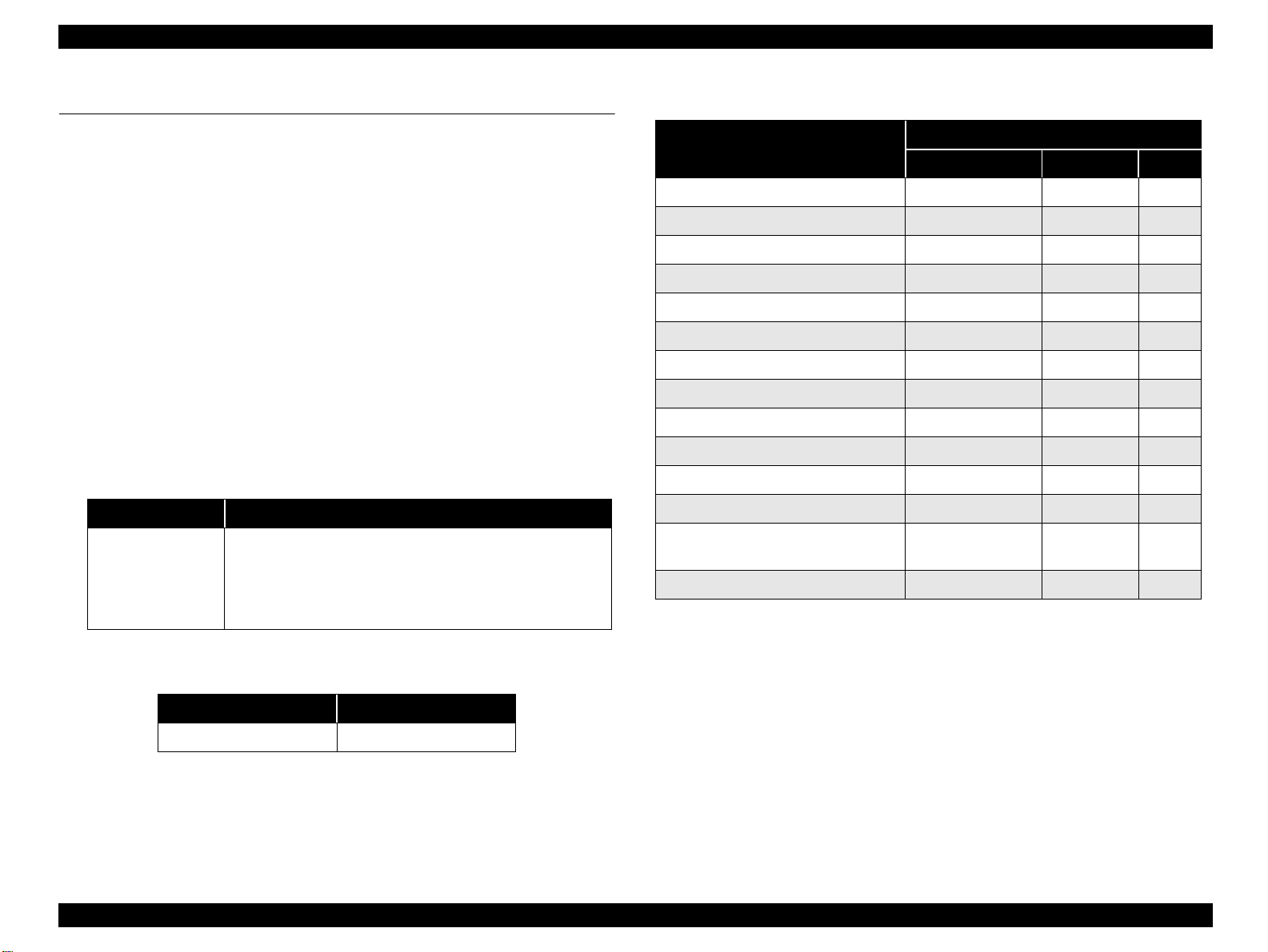
2.1.8 Printing mode
The print resolution and printing method are determined automatically by setting the
media type and print quality (It is able to set by slider bar) in the printer driver as
following table. Following table show you the detail setting in the “Auto” mode.
Print media Slide bar Resolution Print mode
Table 2-6. Printing mode for Black mode
High
Speed*1
Micro
weave
Dot size*2
Table 2-5. Printing mode for Color mode
Print media Slide bar Resolution Print mode
Speed 120 x 120 Economy ON OFF ND-3dot
Plain paper
360 dpi Ink jet
paper
Photo Quality
ink jet paper
Matte Paper-
Heavyweight
Photo paper
Photo Quality
Glossy Film
Ink Jet
transparencies
Default 360 x 360 Normal 360 ON ON MSD2
Quality 720 x 720 Photo 720 ON ON VSD 6pl
N/A 360 x 360 Normal 360 OFF ON MSD2
Default 360 x 360 Fine 360 ON ON MSD2
Quality 720 x 720 Photo 720 ON ON VSD 6pl
Default 360 x 360 Fine 360 ON ON MSD2
Quality 720 x 720 Photo 720 ON ON VSD 6pl
Default 360 x 360 Fine 360 ON ON MSD2
Quality 720 x 720 Photo 720 ON ON VSD 6pl
N/A 720 x 720 Photo 720 OFF ON VSD 6pl
N/A 360 x 360 Normal 360 OFF ON MSD2
High
Speed*1
Micro
weave
Dot size*2
Speed 120 x 120 Economy ON OFF ND-3dot
Plain paper
360 dpi Ink jet
paper
Photo Quality
ink jet paper
Matte Paper-
Heavyweight
Photo paper
Photo Quality
Glossy Film
Ink Jet
transparencies
Default 240 x 240 Normal 240 ON ON MSD1
Quality 360 x 360 Fine 360 ON ON MSD2
N/A 360 x 360 Normal 360 OFF ON MSD2
Default 360 x 360 Fine 360 ON ON MSD2
Quality 720 x 720 Photo 720 ON ON VSD 6pl
Default 360 x 360 Fine 360 ON ON MSD2
Quality 720 x 720 Photo 720 ON ON VSD 6pl
Default 360 x 360 Fine 360 ON ON MSD2
Quality 720 x 720 Photo 720 ON ON VSD 6pl
N/A 720 x 720 Photo 720 OFF ON VSD 6pl
N/A 360 x 360 Normal 360 OFF ON MSD2
NOTE: *1: High speed means Bi-directional printing.
*2: ND means Normal dot. MS means Multi Shot Dot.
VSD means Variable Shot dot.
NOTE: *1: High speed means Bi-directional printing.
*2: ND means Normal dot. MS means Multi Shot Dot.
VSD means Variable Shot dot.
Operating Principles Overview 40

Stylus C40UX/C40SX/C20UX/C20SX Revision B
2.2 Electrical Circuit Operating Principles
The electric circuit of the Stylus C40UX/C40SX/C20UX/C20SX consists of the
following boards.
Main board: C413 MAIN (USB)
C413 MAIN-B (Parallel)
Power supply board: C417 PSB/PS E Board
NOTE: The C413MAIN/-B board is used for the product in the firs t ma ss
production and it will be changed to C413MAIN-C/-D board at an early
date. The major difference is that a single chip which integrates the
ASIC, CPU and PROM is used on the C413MAIN-C/-D board.
C413 MAIN-C (USB)
C413 MAIN-B (Parallel)
This section provi des opera ting pr inciples o f C413 MAIN /B Board and C417 PSB/PS E
Board. Refer to Figure 2-19 for the major connection of the each boards and their
roles.
Printer Mechanism
C413 MAIN-A/B Board
CR Motor
2.2.1 C417 PSB/PSE board
The power supply boards of Stylus C40UX/C40SX/C20UX/C20SX use a RCC
(Ringing Chalk Converter) circuit, which generates +36VDC for drive line and
+5VDC for logic line to drive the printer. The application of the output voltage is
described below.
Table 2-7. Application of the DC Voltages
Voltage Application
• Motors (CR Motor, PF Motor)
+36VDC
AC voltage input from AC inlet first goes through filter circuit that removes high
frequency components and is then converted to DC voltage via the rectifier circuit and
the smoothing circuit. DC voltage is then lead to the switching circuit and FET Q1
preforms the switching operation. By the switching operation of the primary circuit,
+36VDC is generated and stabilized at the secondary circuit.
• Printhead com m on voltage
• Printhead nozzle selector 36V drive volt a ge
PF Motor
+5VDC
Print Head
HP/PE/IC Sensor
+36VDC
C417 PSB/PSE
Board
Figure 2-19. Electric Circuit
Operating Principles Electrical Circuit Operating Principles 41

Stylus C40UX/C40SX/C20UX/C20SX Revision B
The C417 PSB/PSE board has the various control circuits to stop voltage output if a
malfunction occurs on the power supply board or the main board while the printer
mechanism is on duty. Following explains each control and protection circuit.
+36V line constant voltage control circuit:
The output level of +36V line is monitored by a R92, R93,Q91,ZD51.
When + 36V line reaches about 36.4V, ZD51 has a continuity with and PC1 start
the operation via Q91. Consequently, Q1 switching operation is controlled by this
circuit to stabilize the 36V line.
+36Vline over voltage protection circuit:
The output voltage line is monitored by ZD52,ZD87. If the output level of the
voltage level of +36DC line exceeds +48V, this circuit stops the operation of the
switching FET Q1 via PC1,Q82,Q83 and prevent s high voltage from applie d to the
secondary side
+36Vline over current protection circuit:
The output voltage is monitored by the F51. When the abnormal current is
detected by F51, F51 is fused and cut off the +36V line output to the Main board
+5V line over voltage protection circuit:
The output voltage level of the +5V line is monitored by ZD53.
If the output level of the voltage level of +5DC line exceeds +7V, this circuit
stops the ope ration of the swi tching FET Q1 via PC1,Q82,Q83and prevents high
voltage from applied to the secondary side.
+36VDC over
current protection
+5VDC+36VDC
F51
ZD51,R92,93,Q91
+36VDC Line
Constant Control
C51
Smoothing
Circuit
TRANS(T1)
ZD53
+5VDC line
over voltage
limitation
ZD52,87
+36VDC line
over voltage
limitation
PC1
Photo
Coupler
Smoothing
Circuit
Over Current
Protection
Main
Switching
Filter Circuit
Feed back circuit
Full Wave
rectifier circui t
Figure 2-20. C417 PSB/PSE Board Block Diagram
Operating Principles Electrical Circuit Operating Principles 42

Stylus C40UX/C40SX/C20UX/C20SX Revision B
2.2.2 C413 MAIN/B Board
The printer mechanism is controlled by C413MAIN. On this MAIN board, 3.3V
regulator IC is not mounted and all IC is driven with 5.0 V.
See Figure for the C413 MAIN/B board block diagram.
PROM 4M
(IC6)
CR1
Address
Data
E01A24CA
CPU (IC1)
D-RAM 1M
(IC5)
Reset IC
(IC2)
EEPROM
(IC3)
Motor Driver
(IC10)
Common Driver
(IC9)
Common Driver
(IC7)
+5V
Q2 & Q3
CN4
CN12
CN7
CN9
CN7 Parallel I/F
CN3 USB
(C413MAIN)
HP/PE/IC Sensor
CR Motor
PF Motor
Head
(C413MAIN-B)
2.2.2.1 Main elements
Table 2-8 shows the function of the each main elements on C413MAIN.
Table 2-8. Main Elements
IC Location Function
ASIC
E01A24NA
IC1
PROM IC6
RAM IC5 Bus= 16 bit, 1Mbit DRAM
AT93C46 IC3
BH6150F-E2 IC2
E09A39RA IC9
XC901503FNR2 IC10
74LVX161284 IC7 IEEE1284 parallel I/F transceiver IC.
16bit CPU mounted on the MAIN board is driven by
clock frequency 24MHz and controls the printer.
• Capacity 4MB, Bu s = 16 bit
• Program for CPU
1kbit EEPROM
• Default value setting
• Parameter backup
Reset IC
• For +5V; reset when +4.2V is detected
• For +36V, reset when +2 9.2 is detected
Head drive control HIC
• Generates head common voltage.
• CR motor driver
•PF motor driver
• +5V regulator
Figure 2-21. Block Diagram for the (C413 MAIN/B) Board
Following shows you the major characteristic of this main board.
Timer IC & Lithium battery are not mounted
Unlike the previous products, the Timer IC and the Lithium battery are not
mounted on the Main board. So, this product perform the Power-on cleaning or
Timer cleaning based on the time command which is sent from the printer driver.
As for the detail, refer to the 2.1.7 Ink Sequence.
D-RAM
1Mbit D-RAM is mounted on the Main board.
One CPU controls the all function on the main board.
Operating Principles Electrical Circuit Operating Principles 43

TROUBLESHOOTING
CHAPTER
3

Stylus C40UX/C40SX/C20UX/C20SX Revision B
3.1 Overview
This chapter describes how to identify troubles in two levels: unit level repair and
component level repair. Refer to the flowchart in this chapter to identify the defective
unit and perform component level repair if necessary. This chapter also explains motor
coil resistance, sensor specification and error indication.
START
Unit level Troubleshooting
Unit repair
Assemble & Adjustment
END
Table 3-1. Motor, Coil Resistance
Motor Location Check Point Resistance
CR Motor CN12
PF Motor CN7
Pin 1 and 3
Pin 2 and 4
Pin 1 and 3
Pin 2 and 4
9.6 Ohms
(at 25
7.35 Ohms ±10%
(at 25
±
C/ phase)
°
C/ phase)
°
Table 3-2. Sensor Check Point
Sensor Nam e Check Point Signal Level Switch Mode
Off
• Out of HP range
• No paper
•Detect the I/C
On
• Within HP range
• Detect the paper
• Not detects the I/C
HP/PE Sensor CN 4/Pin 1 and 2
Thermistor
(THM)
TH1 (on the Head
driver board)
Less than 0.7V
More than 2.4V
Analog signal 10 K (at 24
10%
C)
°
Figure 3-1. Troubleshooting Flowchart
Troubleshooting Overview 45

Stylus C40UX/C40SX/C20UX/C20SX Revision B
3.2 Troubleshooting with LED Error Indicat ions
This section describes how to troubleshoot the problem when the printer indicates an
error at power on and can not print. The Stylus C40UX/C40SX/C20UX/C20SX can
detect the following six errors and seven status, and indicates them with the LEDs, as
shows below.
Table 3-3. Error Indicator of Operation Panel
Printer Status
Power ON condition On - 10
Ink sequence Blink - 6
Ink Cartridge change mode Blink - 5
Data processing Blink - 9
Paper Out - On 4
Paper jam condition - On 3
Ink end (Black) - On → ON 8
Ink level low (Black) - Blink → Blink 8
Ink end (Color) - On → ON 8
Ink level low (Color) - Blink→ Blink 8
Ink end (Black and Color) - ON → ON 8
No Ink Cartridge (Black and Color) - On 7
Maintenance request
(Ink Overflow Counter error)
Fatal error Off On 1
"
- " : Indicator status don't change.
Power Error
Alt Blink Alt Blink 2
" A -> B " :A is a indicator condition when carriage is on Home Position.
B is a indicator condition in Ink exchange sequence.
Indicators
Priority
See the following tables which show the error conditions and corresponding
possible causes:
Table 3-4. Error Condition and possible cause
Symptom Poss ible Cause Check tabl e
• The friction of the LD roller is lowered due
to the paper dust.
Paper out error indication
(Paper is not loaded
correctly)
Paper jam error indication
Multiple papers are always
loaded
Paper is always loaded
without any print job
Fatal error indication
• The clutch mechanism is broken.
• Tension spring 0.143 come off in the clutch
mechanism.
• Compression spring 1.47 comes off.
• Tip of Change lever has any damage.
• PF motor is broken.
• Star wheel assembly is not assembled on
the Paper eject frame.
• The Spur gear 10.8 is not assembled
correctly.
• The paper guide front is not assembled
correctly or has any dam age.
• The PE detection lever dose not move
smoothly.
• The paper return plate dose not work
correctly.
• The Change lever is broken in th e Clutch
mechanism.
• HP sensor lever or PE sensor lever dose not
move smoothly.
• HP/PE sensor is defective.
• CR motor is defective.
• PF motor is defective.
• Main board is def e ctive.
• Printer Housing dose not secured with
screw on -the printer mechanism.
Table 3-5
Table 3-6
Table 3-7
Table 3-8
Table 3-9
Table 3-10
Table 3-13
Table 3-14
Table 3-14
Table 3-15
Table 3-15
Troubleshooting Troubleshooting with LED Error Indications 46

Stylus C40UX/C40SX/C20UX/C20SX Revision B
Table 3-4. Error Condition and possible cause (continued)
Symptom Possible Cause Check table
Any error indication is not
displayed. But, the paper is
not ejected completely.
Paper jam dose not occur.
Dot missing occur and it is
not recovered with CL
Print quality is not good
• Vertical banding
• Horizontal banding
• Printing is blurred
• Ink stains the paper
• Paper eject roller gear is disengaged from
the pump’s gears.
• The Paper ejec t frame is not assembled in
the Paper eject frame.
• Pump unit dose not ab s orb t he i nk fro m the
printhead.
• Cap unit dose not stick on the su rface of th e
printhead completely.
• The printhead is broken.
• The head FFC has any damage.
• The main board i s defective.
• The accuracy of the CR motor is lowered.
• The lack of the lubricant around the CR
unit.
• The both I/C is not held in the CR unit
securely.
• The Paper eject frame is deformed.
• Any foreign mate rial is sticking around the
printhead.
• Paper feed accuracy is lowered.
• Printer driver setting is not suitable.
• Paper path has ink stain somewhere.
Figure 3-16
Figure 3-17
Figure 3-18
Figure 3-19
Table 3-20
Table 3-21
Table 3-22
If the problem fits to the detail phenomenon in the table, make sure the check point and
repair the product following the corresponding remedy mentioned in the table when
you find the defective parts in the check point.
Table 3-5. Paper out error indication
Step
No.
Detail phenomenon Check point Remedy
• Check the surface of the
• Set a cleaning sheet in the
LD roller if the micro
pearl or severe smear is
adhered.
ASF LD roller attempt
to load the paper.
1
But, paper is no t loaded
LD roller
at all. The LD roller
seems slipping.
If it is no problem,
Non-adhesive Area
proceed the next step.
• If the problem is not
ASF up side down. Then
holding the top edge, try
to load the paper from the
Printer driver. The micro
pearl on the LD roller
surface is removed. To
remove severe smear,
staple a cloth moistened
with alcohol to a post card
and clean the roller in the
same manner.
(Use a post card
for the base sheet)
CL Sheet
Adhesive Area
This side down
Staplers
Cloth moistened
with alcohol
solved, replace the LD
unit with new one.
Troubleshooting Troubleshooting with LED Error Indications 47

Stylus C40UX/C40SX/C20UX/C20SX Revision B
Step
No.
Detail phenomenon Check point Remedy
ASF LD roller dose not
attempt to load the
paper. But, the PF motor
and the Spur gear 35.2 is
rotating.
2
Spur gear 35.2
ASF LD roller dose not
attempt to load the
3
paper. But, the PF motor
and the Spur gear 35.2 is
rotating.
Table 3-6. Paper out error indication
• Check if the clutch
tooth is broken.
Clutch tooth
If it is no problem, proceed
the next step.
1. Check if the tension
spring 0.143 co m es off
in the Clutch
mechanism.
Tension spring
0.143
• Replace the LD unit with
new one.
1. Set the tension spring
0.143 in the clut ch
mechanism.
2. Set the Compression
spring 1.47 in the Chang e
lever.
Step
No.
Detail phenomenon Check point Remedy
When the print data is
sent to the printer, ASF
LD roller continue to
load the paper even if
the first paper is loaded
4
to the PF roller and the
paper is ejected while
the ASF hopper is
flapping.
When the printer is
turned on, PF motor
5
dose not operate at all in
the power on sequence .
Table 3-7. Paper out error indication
1. Check if the tip of the
Change lever has any
damage.
Change lever
Comp. spring 1.47
2. Check if the
Compression spring
1.47 comes off from the
Change lever.
If it is no p roble m, proc eed
the next step.
1. Chec k if the PF motor
connector is connected
to the CN7.
2. Chec k if the PF motor
coil resistance is about
7.35 ohm by using tes ter
Refer to Table 3-1.
1. Replace the Change l ever
(Printer mechanism) with
new one.
2. Set the Compression
spring 1.47 in the Change
lever.
1. Co nnect the PF motor
connector to the CN7 on
the Main board.
2. Replace the Printer
mechanism with new one.
3. If the problem is not
solved, replace the Main
board with new one .
Troubleshooting Troubleshooting with LED Error Indications 48

Stylus C40UX/C40SX/C20UX/C20SX Revision B
Step
No.
Detail phenomenon Check point Remedy
Paper is not ejected
completely and jam med
1
around the Paper eject
frame.
2 Ditto
Table 3-8. Paper jam error indication
• Check if the star wheel
assembly is assembled
in the Paper eject frame.
Star wheel assy
If it is no problem, proceed
the next step.
• Check if the Paper eject
roller is rotating
correctly.
Spur gear 60
• Replace the Paper eject
frame with new one.
• Set the tip of the Spur gear
60 to the PF motor pinion
and assemble it correctly.
Step
No.
Detail phenomenon Check point Remedy
Paper is loaded
correctly from ASF.
But, after complete the
3
print job, paper jam
indicated on the screen
without any paper jam.
Table 3-9. Paper jam error indication
• Check if the Torsion
spring 0.22 comes off
on the both PE sensor
lever.
Tension spring 0.22
PE sensor lever
• If the Torsion spring 0.22
is not set on the correct
position, set it correctly. If
any paper dust is placed
around the PE sensor
lever, remove it.
• If it is no problem,
proceed the next step.
PF motor pinion
If it is no problem, proceed
the next step.
Troubleshooting Troubleshooting with LED Error Indications 49

Stylus C40UX/C40SX/C20UX/C20SX Revision B
Step
No.
Detail phenomenon Ch eck po int Remedy
The PF roller
continues to turn
when the printer’s
power is turned on.
4
Table 3-10. Paper jam error indi cation
1. Check if the Torsion
spring 0.22 comes off
on the both PE sensor
lever
Tension Spring 0.22
PE sensor lever
2. Check if the Torsion
spring 0.22 comes off
on the both HP/IC
sensor lever
HP/IC sensor lever
Torsion spring 0. 22
3. Check if the CN4
connector cable for HP/
PE sensor cable is
disconnected on the
Main board or sens or.
4. Check if the HP/PE
sensor operate s
correctly by using the
tester. Refer to Table
3-2.
1. If the Torsion spring 0.22
2. If the Torsion spring 0.22
3. Connect the CN4
4. Replace the LD unit with
5. If the problem is not
is not set on the correct
position, set it correctly. If
any paper dust is placed
around the PE sensor
lever, remove it.
is not set on the correct
position, set it correctly. If
any paper dust is placed
around the HP/IC sensor
level, remove it.
connector cable to the
CN4 on the Main board.
new one.
solved, replace the Main
board with new one.
Step
No.
Step
No.
Detail phenomenon Check point Remedy
When the printer is
turned on, the CR unit
5
dose not move at all in
the power on sequence.
Detail phenomenon Check point Remedy
“Ink Out error” is
displayed regardless
of whether a new ink
cartridge is installed
or not.
1
Table 3-11. Paper Jam Error indication
1. Check if the CR motor
connector is connected
CN12 on the Main
board.
2. Check if the coil
resistance of the CR
motor is about 9.8 ohm
by using the tester.
Refer to Table 3-1.
1. Connect the CR motor
connector to the CN12 on
the Main board.
2. Replace the CR motor
with new one.
3. If the problem is not
solved, replace the Main
board with new one .
Table 3-12. Ink Out error indication
1. Check if the HP/IC
detection lever is
damaged.
2. Check i f the cover
cartridge is damaged.
1. Replace the LD unit with
new one.
2. Replace the cover
cartridge with a new one.
Troubleshooting Troubleshooting with LED Error Indications 50

Stylus C40UX/C40SX/C20UX/C20SX Revision B
Table 3-13. Multiple papers are always loaded
Table 3-15. Fatal Error indication
Step
No.
1
Detail phenomenon Check point Remedy
Any error indication is
not displayed on the
monitor. But, multiple
papers are always
loaded from ASF.
Table 3-14. Paper is always loaded without any print job
Step
No.
1
Detail phenomenon Check point Remedy
Paper is always loaded
from ASF without any
print job.
ASF hopper continue
to flapping when the
printer is turned on.
Check if the Paper return
plate is operating correctly
in the ASF when the paper
is loaded.
Check if the tip of the
Change lever has any
damage.
Change
lever
• Assemble the torsion
spring 26 in the ASF
frame.
Torsion spring 26
Replace the Change lever
(Printer mechanism) with
new one.
Step
No.
Detail phenomenon Check point Remedy
When the printer is
turned on, it sounds
strange noise and the
4
CR unit is stopped
around the CR lock
lever.
1. Check if the
compression spring 1.47
is installed securely on
the change lever.
Change lever
Comp. spring 1.47
2. Check if the PF motor is
operated. Check the
CN7 connector and the
coil resistance for PF
motor.
3. If the CR lock lever is
not released even if the
PF motor rotate in the
power on sequence,
check if on e of the g ears
has any damage in the
PF motor torque
transportation path.
Refer to Figure 2-15.
1. Install the compression
spring 1.47 secu r e ly.
2. Connect t he PF motor
cable to CN7 on the Main
board.
Replace the PF motor
with new one.
3. Replace the Printer
mechanism with new one.
4. If the problem is not
solved, replace the Main
board with new one.
Troubleshooting Troubleshooting with LED Error Indications 51

Stylus C40UX/C40SX/C20UX/C20SX Revision B
Table 3-16. Paper is not ejected completely without any error indication
Table 3-17. Dot missing occur and it is not recovered with CL
Step
No.
Detail phenomenon Check point Remedy
Printing is normal. But,
the paper is not ejected
1
completely and the
bottom ar ea stay a round
the Paper eject frame.
1. Check if the Paper eject
roller rotate when the
paper is ejected.
2. Check if the Paper eject
frame is secured with
the three fixing screws
to the Main frame.
Front frame
Screws
1. Assemble th e Spur gear
60 to the PF motor pinion.
Spur gear 60
PF motor pinion
2. Secure the Front frame
with the two fixing screws
to the Main frame.
Step
No.
Detail phenomenon Check point Remedy
In the CL sequence, the
pump unit seems work
correctly. But, ink is
not ejected to the waste
1
ink pad at all.
Moreover, any ink is not
absorbed from the head
to the cap.
1. Check if ink is ejected
to the waste ink pad via
pump unit in the CL
sequence.
2. Check if there is any
foreign material around
the seal rubber parts o n
the cap asse m bly.
Cap seal rubber parts
3. Check if any damage is
observed arou nd the
seal rubber parts on the
cap assembly.
4. Check if the
compression spring
is assembled in the Cap
assembly correctly.
1. If ink is not ejected at all
to the waste ink pad in the
CL sequence, proceed the
following check point 2).
2. Remove the foreign
material around the seal
rubber parts.
3. Replace the Printer
mechanism with new one.
4. Replace the Printer
mechanism with new one.
Compression
spring
Troubleshooting Troubleshooting with LED Error Indications 52

Stylus C40UX/C40SX/C20UX/C20SX Revision B
Table 3-18. Dot missing occur and it is not recovered with CL
Table 3-19. Dot missing occur and it is not recovered with CL
Step
No.
Detail phenomenon Check point Remedy
In the CL sequence, the
pump unit seems work
correctly. But, any ink
is not ejected to waste
ink pad.
1
Moreover, any ink is
not absorbed from the
head to the cap.
5. Check i f the Pump
tube is connected to
the bottom of the Cap
assembly correctly
Pump tube
connection point
6. Check if the pump tube
has a little slack
between the Cap
assembly and the pump
unit when the Cap
assembly is slide up
completely.
Cap assy.
Tube
5. Replace the Pr in ter
mechanism with new one.
6. Pump unit may coil the
pump tube inside the unit.
In this case, pull out the
coiled tube from the
pump unit carefully.
After that, connect the
pump tube to the Cap
assembly after placing the
tube corr e ctly.
Step
No.
Detail phenomenon Check point Remedy
In the CL sequence,
ink is ejected to the
Waste ink pad (this
means pump unit & cap
unit are working
2
correctly). But, the dot
missing is not solved at
the specific nozzles
even if the several CLs
are performed.
In the CL sequence, ink
is ejected to the Waste
ink pad. But, dot
3
missing is occurred on
all nozzle in the printin g
and is not solved in the
several C L s .
1. Check if the segment in
the nozzle check patter
is reduced every CL &
Nozzle check pattern
printing.
2. Check if any damage is
observed on the Head
FFC.
1. Check if the Head FFC
is connected to th e CN9
on the Main board or
Head FFC.
1. Replace the I/C with new
one in the I/C replacement
sequence.
2. Replace the Head FFC
with the new one.
3. Replace the printhead
with new one.
1. Connect the H ead FFC
securely to the CN9 on the
Main board or Printhead.
2. Repla ce the Printhead
with new one.
3. Replace the Main board
with new one.
Pump unit
7. If the problem is not
solved, replace the Printer
mechanism with new one.
Troubleshooting Troubleshooting with LED Error Indications 53

Stylus C40UX/C40SX/C20UX/C20SX Revision B
.
Table 3-20. Print quality is not good
Table 3-21. Print quality is not good
Step
No.
Detail phenomenon Check point Remedy
Vertical banding is
appeared against the CR
movement directi on.
And it looks like uneven
printing.
1
CR movement
direction
1. Check if each segment
is printed correctly in
the nozzle check
pattern.
Check if the CR rail
2.
on the main frame is
not extremely dirty,
etc.
3. Check if the surface of
the CR sliding portion
on the Paper eject frame
has enough oil.
G-58 lubrication
4. Check if the surface of
the Paper eject frame is
flat.
1. Perform the CL and check
the nozzle check pattern.
Clean the CR rail on
2.
the main frame and
lubricate G-58.
3. Clean the surface of the
CR sliding portion on the
Paper eject frame and
lubricate specific amount
of the G-58.
4. Replace the P a per eject
frame with new one.
Step
No.
Detail phenomenon Check point Remedy
1 Ditto
Micro banding appears
horizontally against the
paper feeding direction
and it appears with the
same width.
2
CR movement
direction
1. Check if each segment
is printed correctly in
the nozzle check
pattern.
2. Check if the suitable
paper is used
according to the
printer driver setting.
3. Check if the Paper
feed roller is dirty.
4. Check if the following
parts do not have any
damage.
Spur gear 60
5. Replace the following
parts.
•CR motor
• CR timing belt
• Compression spring 11.8
1. Perform the CL and
check the nozzle check
pattern. by using the
Adjustment program.
2. Use the suitable paper
according to the printer
driver setting.
3. Clean the su rface of the
PF roller carefully with
the soft bru sh
4. Replace the Printer
mechanism with new
one.
PF motor pinion
5. Replace the Printhead
with new one.
Troubleshooting Troubleshooting with LED Error Indications 54

Stylus C40UX/C40SX/C20UX/C20SX Revision B
Table 3-22. Print quality is not good
Step
No.
Detail phenomenon Check point Remedy
3 Printing is blurred
4 Ink stains the paper
1. Check if the suitable
paper is used
according to the
printer driver setting.
2. Check if the correct
head ID is stored in the
EEPROM by using the
Adjustment progra m.
1. Check if the following
parts are stained with
ink.
• PF roller
• Paper guide front
• Paper eject roller.
2. Check if there is some
ink drops around the
backside of the
printhead.
3. If the bottom area of
the printed paper has
ink stain, check if the
Paper eject frame is
secured with three
screws.
4. If the bottom area of
the printed paper has
ink stain, check if the
Paper eject frame is
bent upward.
1. Use the suitab l e paper
according to the driver
setting.
2. Input 6 digits code of
the head ID into the
EEPROM by using the
Adjustment program.
1. Clean the ink stained
parts with soft cloth.
2. Wipe off the ink drop
with the soft cloth
carefully.
3. Secure the screws fixing
the Paper eject frame.
4. Replace the Paper eject
frame with new one.
Troubleshooting Troubleshooting with LED Error Indications 55

DISASSEMBLY AND ASSEMBLY
CHAPTER
4

Stylus C40UX/C40SX/C20UX/C20SX Revision B
4.1 Overview
This section describes procedures for disass embling the main components of the Stylus
C40UX/C40SX/C20UX/C20SX. Unless otherwise specified, disassembly units or
components can be reass embled by r eversi ng the disa ssembly proced ure. Thi ngs, i f no t
strictly observed, that could result in injury or loss of life are described under the
heading “Warning”. Precautions for any disassembly or assembly procedures are
described under the heading “CAUTION”. Chips for disassembling procedures are
described under the heading “CHECK POINT”.
If the assembling procedure is different from the reversed procedure of the
disassembling, the procedure is described under the heading “REASSEMBLY”.
Any adjustments required after dis assembling the un its are describe d under the h eading
“ADJUSTMENT REQUIRED”. When you have to remove any units or parts that are
not described in this chapter, refer to the exploded diagrams in the appendix.
Read precautions described in the next section before starting.
4.1.1 Precautions
See the precautions given under the handling “WARNING” and “CAUTION” in the
following column when disassembling or assembling the Stylus C40UX/C40SX/
C20UX/C20SX.
W A R N I N G
Disconnect the power cable before disassembling or assembling
the printer.
If you need to work on the printer with power applied,
strictly follow the instructions in this manual.
Wear protective goggles to protect your eyes from ink. If ink gets
in your eye, flush the eye with fresh water and see a doctor
immediately.
Always wear gloves for disassembly and reassembly to avoid
injury from sharp metal edges.
To protect sensitive microprocessors and circuitry, use static
discharge equipment, such as anti-static wrist straps, when
accessing internal components.
Never touch the in k or wasted ink with bare hands. If ink comes
into contact with your skin, wash it off with soap and water
immediately. If irritation occurs, contact a physician.
When a lithium ba ttery is insta lled o n the main board of this
printer, make sure to observe the following instructions when
serving the battery:
1. Keep the battery away from any metal or other batteries so that
electrodes of the opposite polarity do not come in contact with
each other.
2. Do not heat the battery or put it near fire.
3. Do not solder on any part of the battery. (Doing so may result in
leakage of electrolyte f rom the b attery, bur ning or expl osion. The
leakage may affect other devices close to the battery.)
4. Do not charge the battery. (An explosion may be generated inside
the battery, and cause burning or explosion.)
5. Do not dismantle the battery. (The gas inside the battery may hur t
your throat. Leakage, burning or explosion may also be resulted.)
6. Do not install the battery in the wrong direction. (This may cause
burning or e xplosion.)
Danger of explosion if the battery is incorrectly replaced.
Replace only with the same or equivalent type recommended by
the manufacture. Dispose the used batteries according to
government’s law and regul ation s .
Disassembly and Assembly Overview 57

Stylus C40UX/C40SX/C20UX/C20SX Revision B
W A R N I N G
C A U T I O N
Avant de commencer, assurez vous que l’imprimante soit eteinte
et que le cordon d’alimentation soit debranche.
Lorsque vous changez la pile au lithium, assurez vous que la
nouvelle respecte bien les caracteristiques requises.
Lorque que vous installez la pile au lithium, faites attention a
l’inserer dans le bon sens en respectant la polarite.
Veillez a jeter les piles usagees selon le reglement local.
Ne rechargez pas les piles au lithium.
Risque d’explosion si la pile est remplacée incorrectment. Ne
remplacer que par une pile du même type ou d’un type équivalent
recommandé par le fabricant. Eliminer les piles déchargées selon
les lois et les règles de sécurité en vigueur.
C A U T I O N
Never remove the ink cartridge from the carriage unless this
manual specifies to do so.
When transporting the pri nter after installing the ink ca rtridg e,
be sure to pack the printer for transportation without removing
the ink cartridge.
Use only recommended tools for disassembling, assembling or
adjusting the printer.
Observe the specified torque when tightening screws.
Apply lubricants and adhesives as specified. (See Chapter 6 for
details.)
Make the specified adjustments when you disassemb le the
printer.
(See Chapter 5 for details.)
When assembling, if an ink cartridge is removed and needs to be
installed again, be sure to install a new ink cartridge because of
the following reasons;
1. Once the ink cartridge mounted on the printer is removed, air
comes in and creates bubbles in the cartridge. These bubbles clog
ink path and cause printing malfunction.
2. If an ink cartridge in use is removed and is reinstalled, ink
quantity will not be detected correctly since the counter to check
ink consumption is cleared.
Because of the reasons above, make sure to return the printer to
the user with a new ink cartridge installed.
Disassembly and Assembly Overview 58

Stylus C40UX/C40SX/C20UX/C20SX Revision B
4.1.2 Tools
Use only specified tools to avoid damaging the printer.
Table 4-1.
Name Supplier Parts No.
Phillips Screw Driver (No.1) EPSON B743800100
Phillips Screw Driver (No.2) EPSON B743800200
Nipper EPSON B740500100
Tweezers EPSON B741000100
4.1.3 Screws
Table 4-2.
No. Name and Specification Outward Form
1 CBS 3x6
2 CBP 3x8
3 CBS (P2) 3x6
4 CBS 3x8
5 C.P.F.S-Tite 3x12
Disassembly and Assembly Overview 59

Stylus C40UX/C40SX/C20UX/C20SX Revision B
4.1.4 Work Completion Check
If any service is made to the printer, use the checklist shown below to co nfirm all works are
completed properly and the printer is ready to be returned to the user.
Table 4-3. Work Completion Check
Classifi-
cation
Main Unit
Adjustment
Item Check Point Status
Self-test Is the operation normal?
On-line Test Is the print in g successful?
Printhead
Carriage
Mechanism
Paper Feeding
Mechanism
Specified
Adjustment
Is ink discharged normally from
all the nozzles?
Does it move smoothly?
Is there any abnormal noise
during its operation?
Is there any dirt or foreign
objects on the CR Guide Shaft?
Is the CR Motor at the correct
temperature?
(Not too heated?)
Is paper advanced smoothly?
• No paper jamming?
• No paper skew?
• No multiple feeding?
• No abnormal noise?
Is the PF Motor at correct
temperature?
Is the paper path free of any
obstructions?
Are all the adjustment done
correctly?
Checked
Not necessary
Checked
Not necessary
Checked
Not necessary
Checked
Not necessary
Checked
Not necessary
Checked
Not necessary
Checked
Not necessary
Checked
Not necessary
Checked
Not necessary
Checked
Not necessary
Checked
Not necessary
Classifi-
cation
Lubrication
Packing
Others
Table 4-3. Work Completion Check (continued)
Item Check Point Status
Specified
Lubrication
Ink Cartridge
Protective
Materials
Attachments,
Accessories
Are all the lubrication made at
the specified points?
Is the amount of lubrication
correct?
Are the ink cartridges installed
correctly?
Have all relevant protective
materials been attached to the
printer?
Have all the relevant items been
included in the package?
Checked
Not necessary
Checked
Not necessary
Checked
Not necessary
Checked
Not necessary
Checked
Not necessary
Disassembly and Assembly Overview 60

Stylus C40UX/C40SX/C20UX/C20SX Revision B
4.2 Disassembly
The flowchart below shows step-by-step disassemb ly procedures. When d isassembling
each unit, refer to the page number shown in the figure.
Upper hous ing
removal
Page 61
ASF unit
removal
Page 63
PS unit
removal
Page 65
CR Motor
removal
Page 73
MAIN board
removal
Page 71
Printhead unit
removal
Page 74
LD unit
removal
Page 76
Paper eject
roller removal
Page 66
Waste ink pad
removal
Page 76
4.2.1 Upper housing removal
1. Move the edge guide to the right until it stops moving. Make sure the edge guide is
in the upper housing’s notch position.
Edge guide
Figure 4-2. Position of Edge guide
Figure 4-1. Disassembling Flowchart
C A U T I O N
Do not remove the Main Frame from the Lower Housing to avoid
the deformation of the Main Frame.
Therefore, you cannot remove the following parts.
Lower Housing
Main Frame
PF Motor
Pump Unit
Cap Unit
PF Roller Assy.
Disassembly and Asse mbly Disassembly 61

Stylus C40UX/C40SX/C20UX/C20SX Revision B
2. Remove the 2 hooks at the front using a precision screwdriver (-).
C A U T I O N
The printer should not turn when the front 2 hooks are removed.
Upper housing
3. Remove the 2 hooks on the sides by pushing the tops of the hooks up.
Figure 4-4. Removing the side hook
4. Remove the 3 hooks at the back using a (-) screwdriver or similar tool.
Figure 4-3. Removing the front hook
Figure 4-5. Removing the back hook
Disassembly and Asse mbly Disassembly 62

Stylus C40UX/C40SX/C20UX/C20SX Revision B
4.2.2 ASF unit removal
1. Remove the upper housing. (Refer to Section 4.2.1)
2. Take out the three screws.
CBP 3×8
A D J U S T M E N T
R E Q U I R E D
CBS (P2) 3×6
The Top Margin adjustment is required when the ASF unit is
replaced.
3
1
CBP 3
6
×
Figure 4-6. Removing the ASF unit
3. Pull the ASF unit toward the rear and remove it.
When installing the ASF unit, install the spring in the guide, then
install it while supporting it by hand.
Figure 4-7. reassembling the ASF unit
When reassembling the ASF unit tighten screws form lower
numbers in Figure4-6.
Tightening Torque for screw
- C.B.S 3x6 : 9+/-1 kgf.cm
- C.B.S (P2) 3x6 : 9+/-1 kgf.cm
- C.B.P 3x8 : 6+/-1 kgf.cm
2
Disassembly and Asse mbly Disassembly 63

Stylus C40UX/C40SX/C20UX/C20SX Revision B
4.2.3 Waste ink pad removal
1. Remove the upper housing. (Refer to Section 4.2.1)
2. Remove the ASF unit. (Refer to Section 4.2.2)
3. Remove the Waste ink pa d.
A D J U S T M E N T
R E Q U I R E D
When the Waste ink pad is replaced with a new one, following
service item is required.
Waste ink counter reset operation. (Refer to Section 5.1.12)
tube stopper
Waste ink pad
Figure 4-8. Removing the Waste ink pad
When assembling the Waste ink pad, be sure to set the tip of the
ink tube in the correct position of the Waste ink pad. Otherwise
it will cause ink leakage.
Tip of ink tube
Figure 4-9. Tip of ink tube setting position
Disassembly and Asse mbly Disassembly 64

Stylus C40UX/C40SX/C20UX/C20SX Revision B
4.2.4 PS unit removal
1. Remove the upper housing. (Refer to Section 4.2.1)
2. Remove the ASF unit. (Refer to Section 4.2.2)
3. Disconnect the cable from the conn ector (CN2) on the main board using tweezers,
etc.
4. Take out the 2 screws.
CN2
PS unit
C.B.S 3×6
C.B.P 3×8
When installing the PS unit, make sure the claws are attached to
the hooks on the lower housing.
Figure 4-11. Reassembling the PS unit
Do not insert the pin of the PS cable to the leftmost side of the
connector because the 1st pint of its cable is cut.
Figure 4-10. Removing the PS unit
5. Pull the PS unit out while lifting up on it.
Blue line
marking
2222
3 4
5
Figure 4-12. Connecting the PS cable(CN2)
Tightening Torque for screw
- C.B.S 3x6 : 6+/-1 kgf.cm
- C.B.P 3x8 : 6+/-1 kgf.cm
Disassembly and Asse mbly Disassembly 65

Stylus C40UX/C40SX/C20UX/C20SX Revision B
4.2.5 Paper eject roller removal
1. Remove the upper housing. (Refer to Section 4.2.1)
2. Grip the dowel pin of the PE roller’s gear, turn it clockwise and release the
carriage lock.
Protrusion
4. Take out the two screws.
CBS 3×6
Figure 4-14. Take out the screw
5. Return the carriage to the home position, then remove the Front Frame.
Figure 4-13. Releasing the carriage lock
3. Move the carriage to the center.
Front Frame
Figure 4-15. Removing the Front Frame
Disassembly and Asse mbly Disassembly 66

Stylus C40UX/C40SX/C20UX/C20SX Revision B
6. Slide the PE roller to the left side, then remove the claw extending from the lower
housing.
C A U T I O N
Paper Eject roller
If the Paper eject roller gear and Paper eject roller shaft are
removed or , make sure that neither of the Paper eject roller
shaft hooks is damaged.
If either of the hooks is damaged, it should be replaced with a
new one.
hook
Figure 4-16. Releasing the claw extending
7. Remove the gear from the frame, then remove the Paper eject roller.
Figure 4-18. Hook of Paper eject roller
Tightening Torque for screw
- C.B.S 3x6 screw for Front frame : 6+/-1 kgf.cm
Gear
Figure 4-17. Removing the Paper eject roller
Disassembly and Asse mbly Disassembly 67

Stylus C40UX/C40SX/C20UX/C20SX Revision B
4.2.6 Paper Guide Upper/Left removal
C A U T I O N
1. Remove the upper housing. (Refer to Section 4.2.1)
2. Place the OHP sheet between the Paper Guide Upper/Left and the PF roller by
rotating the protrusion of the Paper Eject roller gear in CW direction.
Perform this operation by the following procedures so that the
coating material of the PF roller does not damage.
Protrusion
3. Press the dowel of the paper guide unit with tweezers, etc., then pull it forward and
remove it.
OHP paper
dowel
Figure 4-20. Removing the Paper Guide Upper/Left
Figure 4-19. Place the OHP sheet
Disassembly and Asse mbly Disassembly 68

Stylus C40UX/C40SX/C20UX/C20SX Revision B
Insert the tip of the spring to the Paper Guide.
1.
1.
1.1.
Figure 4-21. Setting the spring to the Paper Guide
Place the OHP sheet on the PF roller.
2.
2.
2.2.
Assemble the Paper Guide Upper/Left to the Main Frame.
3.
3.
3.3.
Figure 4-23. Assembling the Paper Guide 1
Fix the dowel of the Paper Guide Upper/Left to the hole of the
4.
4.
4.4.
Main Frame by sliding the Paper Guide Upper/Left to the right
side. And, release the spring from the hook of the Paper Guide
Upper/Left.
dowel
OHP paper
Figure 4-22. Placing the OHP sheet
Release the spring
Figure 4-24. Assembling the Paper Guide 2
Disassembly and Asse mbly Disassembly 69

Stylus C40UX/C40SX/C20UX/C20SX Revision B
Eject the OHP sheet from the printer by rotating the protrusion
5.
5.
5.5.
of the Paper Eject roller gear in CW direction.
Protrusion
Figure 4-25. Ejecting the OHP sheet
Disassembly and Asse mbly Disassembly 70

Stylus C40UX/C40SX/C20UX/C20SX Revision B
4.2.7 MAIN board removal
1. Remove the upper housing. (Refer to Section 4.2.1)
2. Remove the ASF unit. (Refer to Section 4.2.2)
3. Remove the PS unit. (Refer to Section 4.2.4)
4. Remove the two hooks, then remove the Switch cover.
Switch cover
Hooks
5. Remove the three screws, then remove the shield cover.
USB Type
CBS 3×6
Parallel Type
Figure 4-26. Removing the Switch cover
C.P.F.S-Tight 3×12
CBS 3×6
Figure 4-27. Removing the Shield cover
Disassembly and Asse mbly Disassembly 71

Stylus C40UX/C40SX/C20UX/C20SX Revision B
6. Disconnec t the four con nectors (CN9, CN4, CN7, CN 12).
CN9
CN4
CN7
CN12
Figure 4-28. Disconnecting the connectors
7. Take out the 1 screw.
CBS 3×8
8. Lift the MAIN board up and remove it.
Tightening Torque for screw
USB Type
- C.B.S 3x6 screw : 9+/-1 kgf.cm
- C.B.S 3x8 screw : 9+/-1 kgf.cm
Parallel Type
- C.B.S 3x6 screw : 9+/-1 kgf.cm
- C.P.F.S-Tight 3x12 screw : 9+/-1 kgf.cm
- C.B.S 3x8 screw : 9+/-1 kgf.cm
A D J U S T M E N T
R E Q U I R E D
When replacing the Main board with a new one, perform the
following service items.
Before removing the Main Board, connect the parallel cable or
USB cable and try to read out the following data by using the
Adjustment program. If this operation succeeds, replace the
Main board and write the read out data to the new Main
board through the Adjustment program. (Refer to Section
5.1.14)
1) I/C Ink consumption counter.
2) Waste ink drain pad counter.
3) EEPROM Initial setting
4) Head ID input
5) Top margin adjustment
6) Bi-D adjustment
In case the above mentioned data are not able to be read out from
the defective Main board, perform the following service items.
Replace the both ink cartridges with a brand new one.
Replace the Waste ink pa d wit h a new one.
Reset the Ink pad counter
Input the EEPROM initial setting value
Input the Head ID
Adjust the Top margin
Adjust the Bi-D alignment.
Figure 4-29. Removing the MAIN board
Disassembly and Asse mbly Disassembly 72

Stylus C40UX/C40SX/C20UX/C20SX Revision B
4.2.8 CR motor removal
1. Remove the upper housing. (Refer to Section 4.2.1)
2. Move the carriage to the center.
3. Press on the driven pulley and loosen the timing belt, then remove the timing belt
from the CR pinion gear.
Timing belt
Driven pulley
CR pinion gear
Figure 4-30. Removing the Timing belt
4. Take out the screw, then remove the CR motor from the frame.
5. Disconnect connector CN7 from the MAIN board then disconnect the cable.
When reassembling the CR motor, it contact the lib of Main
frame after turning clockwise.
lib
Figure 4-32. Reasse mbling the CR motor
CR motor
A D J U S T M E N T
R E Q U I R E D
CBS 3×6
Tightening Torque for screw
- C.B.S 3x6 screw : 9+/-1 kgf.cm
The Bi-D adjustment is required when the CR motor is removed
or replaced. Refer to Table 5-1
Figure 4-31. Removing the CR motor
Disassembly and Asse mbly Disassembly 73

Stylus C40UX/C40SX/C20UX/C20SX Revision B
4.2.9 Printhead unit removal
1. Remove the upper housing. (Refer to Section 4.2.1)
2. Remove the ink cartridges.
3. Move the carriage to the center.
4. Press on the driven pulley and loosen the timing belt, then remove the timing belt
from the CR pinion gear.
Timing belt
Driven pulley
Figure 4-33. Removing the Timing belt
5. Disconnect the FFC from the carriage unit.
CR pinion gear
6. Press on the left and right inside of th e carriage unit, then pull the unit forward and
remove the cover.
Carriage cover
Figure 4-35. Removing the Carriage cover
7. Lift the Printhead unit up and remove it.
FFC
Printhead unit
Carriage unit
Figure 4-34. Disconnecting the FFC
Figure 4-36. Removing the Printhead unit
Disassembly and Asse mbly Disassembly 74

Stylus C40UX/C40SX/C20UX/C20SX Revision B
8. Disconnect the FFC from the connector.
A D J U S T M E N T
R E Q U I R E D
When the Printhead is replaced with a new one, following
adjustments must be performed in the order below: Refer to Table
5-1
1. Initial ink charge
FFC
2. Head ID input
3. Bi-D adjustment
When the Printhead is removed and reinstalled, only the following
adjustment is required. Refer to Table 5-1
1. Head cleaning
2. Bi-D adjustment
Figure 4-37. Disconnecting the FFC
If the Carriage unit is disassembled or replaced with a new one,
make sure that the Carriage timing belt is set in the assembling
groove correctly as following figure.
Timing belt
Disassembly and Asse mbly Disassembly 75

Stylus C40UX/C40SX/C20UX/C20SX Revision B
4.2.10 LD unit removal
1. Remove the upper housing. (Refer to Section 4.2.1)
2. Remove the ASF unit. (Refer to Section 4.2.2)
3. Disconnect the cables which are connected to the LD unit.
4. Disconnect connector CN4 form the MAIN board.
LD unit
Cables
Figure 4-38. Disconnecting the Cables
5. Push the two hooks on the LD unit, then lift it up and remove hook of pump unit
A D J U S T M E N T
R E Q U I R E D
When reassembling the LD unit, make sure that seven hooks are
set to the Main frame.
Figure 4-40. Setting seven hooks
The Top Margin adjustment is required when the LD unit is
replaced.
Hooks
Figure 4-39. Removing the LD unit
Disassembly and Asse mbly Disassembly 76

Stylus C40UX/C40SX/C20UX/C20SX Revision B
4.2.11 Printer mechanism removal
1. Remove the upper housing. (Refer to Section 4.2.1)
2. Remove the ASF unit. (Refer to Section 4.2.2)
3. Remove the PS unit. (Refer to Section 4.2.4)
4. Remove the Printhead unit. (Refer to Section 4.2.9)
5. Remove the Paper eject roller. (Refer to Section 4.2.5)
A D J U S T M E N T
R E Q U I R E D
When the Printer mechanism with a new one, following
adjustments must be performed in the order below: Refer to Table
5-1
1. Initial ink charge
2. Head ID input
3. Top margin adjustment
4. Bi-D adjustment
Disassembly and Asse mbly Disassembly 77

ADJUSTMENT
CHAPTER
5

Stylus C40UX/C40SX/C20UX/C20SX Revision B
5.1 Overview
This section describes the procedure for adjustments required when the printer is
disassembled and assembled for repair or service.
5.1.1 Required Adjustment
Table 5-1 lists all the necessary adjustments for this printer. If any serv ice listed in this
table is carried out, all adjustments corresponding to that service item should be
performed to ensure proper operation of the printer.
Table 5-1. Required Adjustment
Performance
Priority
Replacing part s/
Service item
Replacing the
Main Board
Removing the
Printhead unit
Replacing the
Printhead unit
Replacing the CR
motor
1 2 3 4 5 6 7
EEPROM
initial
setting
c d
NA NA NA NA NA
NA NA
NA NA NA NA NA
Ink pad
Counter
reset
Initial
Ink
Charge
NA
Head
ID
Setting
e f g h
c d
Top margin
Adjustment
NA
Bi-D
Adjustment
c
e
c
USB
ID
Input
NA
NA
NA
NOTE: • “O”: Required Adjustment. The number in the circle shows the required
adjustment order.
“NA”: Not applicable.
• Following ad jus tments are not required on this product.
-Platen Gap adjustment
-Head Angular adjustment.
• When the Main board is replaced with new one, you may have to
replace the following parts also in case the EEPROM parameter back up
function is not available on the defective main board.
* Waste drain ink pad
* Both Black & Color Ink Cartridge
This section describes the detailed procedures of each adjustment by Adjustment
Program.
In this printer, it is necessary to set the adjusting information for each printer
mechanism in order to maintain consistent printing function and quality, eliminating
differences of each printer mechanism’s characteristics. Therefore, in case that the
combination of the printer mechanism and main board changes or the print head is
replaced during the repair service, you must set and sav e the corr ect information to the
MAIN board, using the exclusive adjustment program.
C H E C K
P O I N T
In case any parts is removed and assembled on the repair product
while running the Adjustment program, turn off the printer
certainly.
Replacing the
Printer mechanism
Replacing the
Waste drain ink
pad
Removing or
Replacing the ASF
unit
Removing or
Replacing the LD
unit
NA NA
NA
NA NA NA NA
NA NA NA NA c
c
c d e f
NA NA NA NA NA
c
NA
NA NA
NA NA
Adjustment Overview 79

Stylus C40UX/C40SX/C20UX/C20SX Revision B
5.1.2 Adjustment Program Initial Setting menu
You have to input the following four items before entering the adjustment main menu.
Model name (Stylus C40UX/40SX/20UX/20SX)
For the Stylus C40UX, select Model name “Stylus C40UX.”
Interface setting (LPT1, LPT2, LPT3, EPUSB1, EPUSB2, EPUSB3)
1. When you run this program, the following menu appears. Select the model name
in the screen below.
Figure 5-1. Model Name Selection
2. Select the Interface port number which you connect the printer to your PC.
Figure 5-2. Interface Setting
NOTE: This printer stores model name in the PROM. Therefore, even you select
the model name in the screen above, model name will not stored in the
EEPROM. Selecting model name in the screen above determines
respective special command for each model.
Adjustment Overview 80

Stylus C40UX/C40SX/C20UX/C20SX Revision B
5.1.3 Adjustment Program feature
The adjustment program enables you to set various values correctly to prevent
malfunction and fluctuation of printing quality and printing function caused by
difference in components and assembly when the printer components are replaced
during repair. Basic adjustment items by using this program are shown as fe llows.
C H E C K
P O I N T
No Main Menu Service
1 Adjustment
This program does not operate under DOS or Windows 3.X, NT.
Perform this adjustment pro gram using parallel I/ F or USB.
Table 5-2. Basic adjustment items
EEPROM initial setting
Head ID input
Bi- D adjustment
USB ID input
Top margin
Head cleaning
The user interface of the main menu on this program is shown below.
Figure 5-3. Adjustment program main menu
The “Adjusted item” in the right column shows you the adjusted item which executed
in this program and it is easy to confirm the adjusted value.
Additionally, this program runs under the D4 (IEEE-1284.4) protocol . So, this program
can get the several error statuses even if the printer is error condition, and can control
the printer under the error condition. Following explain you the common function of
the Adjustment program.
Initial ink charge
Refurbishment for DOA
2 Maintenance
Protection counter check
Quit
If you want to exit this program, click the “Quit” button. Following menu is displayed
on the screen. And clicking the “Quit” Button in the following menu exit the
adjustment program completely. Clicking the “Next” button returns to the Top menu
EEPROM check
EEPROM back up data
3 Print A4 pattern A4 pattern will print
(Initial setting menu) of Figure 5-3.
Figure 5-4. Quit function
Adjustment Overview 81

Stylus C40UX/C40SX/C20UX/C20SX Revision B
Get status
This function is used to get the printer status and following figure is displayed on the
screen by clicking the “Get status” button. This fun ction can get the printer status ev en
if the printer is error condition except the main logic circuit failure, and control the
printer by using the D4 mode functions.
C A U T I O N
This program dose not display the “Paper out” error status in the
Bi-d adjustment even if the paper is out in the ASF. When the
paper is out in the ASF, this program continues to send the paper
feed command until the paper is set in the ASF.
Figure 5-5. Get status function
Adjustment Overview 82

Stylus C40UX/C40SX/C20UX/C20SX Revision B
5.1.4 EEPROM initial setting
This function is used when replacing the MAIN board.
Using this function enables writing of the initial setting values to the ne w MAIN
board’s EEPROM.
1. Choose the “EEPROM initial setting” in the Adjustment menu.
Figure 5-6. E EPROM initial setting
5.1.5 Head ID
This adjustment function is required when any of the following parts is replaced.
Printhead
Main board
Printer mechanism
This adjustment function enables you to write printhead Voltage ID into the specific
address of the EEPROM. This operation is considered the most important to maintain
proper ink discharging system. If any ID is not written correctly, it results in white or
color lines and also gives bad influence on dot weight.
1. When replacing any of the parts above, make a note of VH vo ltag e ID in adva nce.
You can find the VH voltage ID on the following position:
Printhead: On the top right face of the printhead.
A 6-digit ID code is printed with the QR code on the label.
Printer mechanism: On the label of the packing box of the printer mechanism.
2. Run the Adjustment program and enter the Adjustment Main menu.
3. Choose the “Head ID” and click it. The menu shown in the next page appears.
2. Click the “OK” button, then the initial setting values are written to the MAIN
board.
Figure 5-7. Head ID input menu
Adjustment Overview 83

Stylus C40UX/C40SX/C20UX/C20SX Revision B
4. Choose the “Check present data” and click the OK button. Following Check
present data menu is displayed. Click the OK button, then readout data is
displayed.
Figure 5-8. Read out the Head ID from the EEPROM
5. Choose the “Change data” item in the Head ID input menu and click the OK
button. Following Head ID input menu is displayed. Input a 6-digit code of the
Head Voltage ID in the following menu.
Figure 5-9. Entering the 6-digits Head ID
6. When the Head ID is input and writes to the EEPROM, the message is displayed
on the bottom column in the menu.
Adjustment Overview 84

Stylus C40UX/C40SX/C20UX/C20SX Revision B
5.1.6 Bi-D
You perform this adjustment to correct differences in printing positions, which is
caused by incorrect of printing timing in right and left directions during the Bidirectional printing. Therefore, you are required to perform this adjustment after
performing the following operat ions.
Replacing the Print mechanism
Replacing the main board
Replacing the CR motor
Replacing the Printhead
Figure 5-11. Bi-d adjustment pattern
1. Choose the “Bi-D” in the “Adjustment menu” as following figure.
Figure 5-10. Choose the Bi-d adjustment
2. Choose the “Print the Bi-d adjustment pattern” in the “Bi-Directional Adjustment
pattern” and click the “OK” button.
NOTE: As shown in the sample, gaps between passes are sometimes created in
different directions among patterns. This unexpected change in direction
is caused by an ink jet printer-specific reason, which is an ink jet printer
inevitably performs a periodical cleaning specified by the flashing timer
even during Bi-D pattern printing, so that the printing direction sudd enly
changes. However, this directional difference among Bi-D patterns
should not be considered, and you can always confirm and adjust the
pattern correctly by referring to gap amount only.
3. Click the “Previous” and go back to the “BI-Directional Adjustment” menu. And
choose the “Adjust” menu and click the “OK” button.
4. Check the printed pattern and find the misaligned dot type.
Choose the
misaligned dot size in the following menu and click the “OK” button.
Figure 5-12. Choose the misaligned dot size
Adjustment Overview 85

Stylus C40UX/C40SX/C20UX/C20SX Revision B
5. By choosing the misaligned dot size, following input menu for the adjustment
value is displayed. Check the printed pattern again and Input the suitable value in
the following menu and click the “OK” button. The input value is written in the
specific address of the EEPROM.
Figure 5-13. Bi-d adjustment input menu
6. To confirm if the adjustment value is suitable, click the “Previous” button and go
back to the “Bi-Directional Adjustment” menu. Choose the “Print the Bi-D
adjustment patter” and click the “OK” button.
5.1.7 USB ID
When you replace the main board with a new one, you have to input the USB ID newly
into the specific address of the EEPROM. When the Printer and the PC are connected
with a USB cable, the USB port driver loads the unique code from the specific address
of the printer’s EEPROM and the provides the USB port number to the unique code.
The USB port driver controls the several USB ports under the Windows 98
environment.
A unique code called USB ID is input to the specific address of the EEPROM in our
manufactory and the following total 18-digit code is used as a USB ID for the EPSON
ink jet printer.
Factory line number (3-digit)
PC number (2-digit)
Input year/month/date/time (hour, minutes, second) (12-digit)
The timer data of the PC is used for this input data.
Number 0
A “0” is automatically added for the last digit in the input program.
In repair activity, we use a 10-digit code of the Serial number for a USB ID. The
remaining 8digits code is generated in the adjustment program and added to the serial
number automatically.
Adjustment Overview 86

Stylus C40UX/C40SX/C20UX/C20SX Revision B
2. Choose the “Input USB ID” and click “OK” button in the “USB ID check/Input”
C A U T I O N
1. Choose the “USB ID input” in the Adjustment menu.
In case the USB ID is not input in the adjustment program after
the main board is replaced to new one, the USB ID may not
possibly unique one. In this case, the USB ID conflicts another
peripheral USB ID in the USB port driver and the another USB
peripheral may not possibly be used with the USB.
menu. Following menu is displayed.
Figure 5-15. Choose the USB ID input menu
3. Check the 10digits code of the serial number on the serial number label stuck
around the rear side of the Upper housing. Input the 10digits code of the serial
number in the input menu and click “OK” button.
Figure 5-14. Choose the USB ID input menu
NOTE: Even though you input irresponsible another 10digits code and click the
“OK” button, the program allow to input the code and write down it the
specific address of the EEPROM. But, there is a possibility that the code
is not unique and the code conflicts another USB ID in the USB port
driver.
Adjustment Overview 87

Stylus C40UX/C40SX/C20UX/C20SX Revision B
5.1.8 Top margin
This function can be used to change the top margin value.
You are required to perform this adjustment after performing the following operations.
Removing or replacing the ASF unit.
Removing or replacing the LD unit.
Replacing the Printer mechanism
Replacing the main board
1. Choose the “Top margin” in the Adjustment menu.
2. Choose the “Print the Top margin” in the “Top margin adjustment” and click the
“OK” button.
Figure 5-17. Top margin adjustment pattern
3. Check that the printed horizontal line is in 2.6mm ~ 7.2mm from the top of the
paper. If it is out of the specific range, perform the Top Margin adjustment by the
following procedure.
4. When adjusting the top margin, select “Adjust” from “Top margin adjustment”,
the click the “OK” button.
Figure 5-16. Choose the Top margin menu
Adjustment Overview 88

Stylus C40UX/C40SX/C20UX/C20SX Revision B
5. The selected value is stored in EEPROM after you select the adjustment v alue and
click
Figure 5-18. Top margin adjustment input menu
6. When checking the adjusted top margin, return to the previous screen by pressing
the “Previous” button, then select “Print the Top Margin” and click the “OK”
button.
5.1.9 Head cleaning
This printhead cleaning is CL1’ and about 1/8 of the brand-new black I/C and 1/17 of
the brand-new color I/C are consumed. Before use this function, check the remaining
ink amount of the both I/C by using the “Get status” function.
1. Choose the “Head cleaning” in the Maintenance menu.
Figure 5-19. Choose the Head cleaning menu
2. Click the “OK” button in the menu. The powerful cleaning is performed.
Adjustment Overview 89

Stylus C40UX/C40SX/C20UX/C20SX Revision B
5.1.10 Initial ink charge
After you replaced any of the following units, perform initial ink charg e and retu rn the
printer after making sure that ink is ejected correctly from the printhead.
After replacing the printer mechanism
After replacing or removing the printhead
C A U T I O N
1. Choose the “Initial ink charge” in the Maintenance menu.
Before you perform the initial ink charge operation, replace the
installed cartridges with new ones, because the ink amount used
for the initial ink charge operation is so large.
5.1.11 Refurbishment for DOA
If you clean the cavity of the printhead and cap assembly, this function will be useful.
C A U T I O N
1. Choose the “Refurbishment for DOA” in the Maintenance menu.
After carry out this function, replace the waste drain ink pad
with new one and reset the Waste drain ink pad counter.
Otherwise, the ink or S46 liquid may leak from the pad during
the transportation.
Prepare the following tool.
*Dummy ink cartridge, Injector, S46 liquid
Do not carry out this program repeatedly. This operation is
available only one time. Excessive operation causes overflow of
the ink and S46 liq ui d .
When yo u ref urbish the repair product by using this program,
do it on your responsibility.
When yo u charge S46 liquid into the dummy ink cartridge with
the Injector, make sure fill out the dummy ink cartridge with S46
liquid. In case enough S46 liquid is not charged into the dummy
cartridge, the printhead will not cleaned and not filled with the
S46 liquid enough in this operation.
Keep the S46 liquid and the dummy in k cartridge clean.
Figure 5-20. Choose the Initial Ink Charge menu
2. Click the “OK” button in the menu. The initial ink charge is performed.
NOTE: As described in the menu message, about 1/4 amount of the Black ink
cartridge and 1/9 amount of the Color ink cartridge are consumed in the
initial ink charge operation.
Figure 5-21. Choose the Refurbishment for DOA menu
Adjustment Overview 90

Stylus C40UX/C40SX/C20UX/C20SX Revision B
2. Set the dummy cartridge in the printer using the ink replacement function.
3. Select “Yes” under “Item,” then click the “OK” button. The “Refurbishment for
DOA” function is then executed.
Adjustment Overview 91

Stylus C40UX/C40SX/C20UX/C20SX Revision B
5.1.12 Protection counter check
The program allows you to check or clear the current protection counter value (waste
ink amount counter).
Check the present counter value
1. Choose the “Check the present counter values” in the “Maintenance” menu and
click the “OK” button.
Figure 5-22. Choose the Check the present counter value
2. After read the Caution description on the above menu, click the “OK” button in the
menu. The present counter value is displayed on the bottom column as following
figure.
Figure 5-23. Present counter value
3. If the present counter value is over 5845 points, we r ecommen d you to replace the
Waste ink drain pad to ne w one.
Adjustment Overview 92

Stylus C40UX/C40SX/C20UX/C20SX Revision B
Clear the present counter value
1. Choose the “Clear the present counter values” in the “Maintenance” menu and
click the “OK” button.
Figure 5-24. Choose the Clear the present counter value
After you read the description on the menu, click the “OK” button.
2.
C A U T I O N
C H E C K
P O I N T
Be sure to replace the installed waste ink pad with a new one after
or before you clear the current protection counter value.
The initial value of the Protection counter is differ by destination
as bellow:
ESP : 0
Exc epting ESP: 2940
Figure 5-25. Clear the present counter value
Adjustment Overview 93

Stylus C40UX/C40SX/C20UX/C20SX Revision B
5.1.13 EEPRON check
You can check the EEPROM data or can write the specific data into the specific
address of the EEPROM directly even if the printer is error condition. (In case one of
the main logic circuit such as CPU, I/F receiver IC, RAM, EEPROM is broken, this
function is not available) Select the “EEPROM check” function in the Maintenance
menu.
The main menu of this function is as following figure. The following two functions are
built in this program.
Figure 5-27. Check the EEPROM data
Change EEPROM data
You can change the specific data stored in the specific address of the
EEPROM.
However, do not use this function except the special case. Careless usage
causes any trouble.
Figure 5-26. EEPROM check function
Check the EEPROM data
You can check the specific data stored in the specific address of the
EEPROM.
Input the specific address with hexadecimal code. Use this function in your
analysis usefully.
Figure 5-28. Chan ge the EEPROM data
Adjustment Overview 94

Stylus C40UX/C40SX/C20UX/C20SX Revision B
5.1.14 EEPROM back up data
This function is used when replacing the MAIN board.
Using this function, the data on the curr ently used MAIN bo ard are b acked up, then the
backed up data can be written to the EEPROM on the new MAIN board after
replacement.
Figure 5-30. Replace the defective main board with new one
C H E C K
P O I N T
1. Choose the “EEPROM backup data” in the Maintenance menu.
This function may fail. If it fails, replace the MAIN board with a
new one, then carry out the specified adjustments in order.
3. The backed up data will be written to the EEPROM on the new MAIN board.
Figure 5-29. EEPROM backup data
2. The EEPROM data on the current MAIN board are backed up by clicking the
“OK” button. The following message is di splayed when the data backu p operation
is completed. Replace the printer’s MAIN board, then turn the power ON again
and click the “OK” button.
Adjustment Overview 95

Stylus C40UX/C40SX/C20UX/C20SX Revision B
5.1.15 A4 pattern will print
The check point for the first black and each color solid pattern
We recommend to use this function to check the repaired product quality in your final
stage of your repair. The following 6 items are printed on the check pattern.
Figure 5-31. A4 Check pattern
C H E C K
P O I N T
(beta pattern 360 x 360dpi normal dot) in the A4 Check pattern
is as follows.
-Any white line is not observed.
-Uneven banding is not observed extremely.
The check point for the second Nozzle check pattern (120dpi) is
as follows.
-Ink is fired from all nozzles.
-Uneven banding is not observed extremely.
The check point for the third Alignment pattern is as follows.
-Each vertical line is printed straight.
If any incorrect printing is observed on the A4 Check pattern,
perform the head cleaning or bi-d adjustment. If the
phenomenon is not improved, replace the printhead or suitable
mechanical parts.
C A U T I O N
Do not print the A4 Check pattern on the EPSON exclusive paper
such as Photo quality ink jet paper. This check pattern is for the
plain paper. So, use the Plain paper for this check pattern printing.
Adjustment Overview 96

Stylus C40UX/C40SX/C20UX/C20SX Revision B
Figure 5-32. A4 Check pattern
Adjustment Overview 97

MAINTENANCE
CHAPTER
6

Stylus C40UX/C40SX/C20UX/C20SX Revision B
6.1 Overview
This section provides information to maintain the printer in its optimum condition.
6.1.1 Cleaning
This printer has no mechanical components which require regular cleaning except the
printhead. Therefore, when returning the printer to the user, check the following parts
and perform appropriate cleaning if stain is noticeable.
C A U T I O N
Never use chemical solvents, such as thinner, benzine, and
acetone to clean the exterior parts of printer like the housing.
These chemicals may deform or deteriorate the components of
the printer.
Be careful not to damage any components when you clean inside
the printer.
Do not scratch the surface (coated part) of PF roller assembly.
Use soft brush to wipe off any dusts. Use a soft cloth moistened
with alcohol to remove the ink stain.
Do not use cleaning sheet included in the media for normal
usage. It may damage the coated surface of PF roller.
If the adhesive surface of the cleaning sheet is set to the ASF LD
roller side and used to clean the ASF LD roller surface, it is no
problem.
Exterior parts
Use a clean soft cloth moistened with water and wipe off any dirt. If the exterior
parts are stained with ink, use a cloth moistened with neutral detergent to wipe it
off.
Inside the printer
Use a vacuum cleaner to remove any paper dust.
ASF LD Roller
If paper dust on the surface of ASF LD Roller lowers the friction, set the adhesive
surface of the cleaning sheet included in the med ia to the s urface o f the ASF ro ller
and repeat loading paper from the ASF.
Maintenance Overview 99

Stylus C40UX/C40SX/C20UX/C20SX Revision B
6.1.2 Service Maintenance
If print irregularity (missing dot, white line, etc.) has occurred or the printer indicates
“Maintenance Error”, take the following actions to clear the error.
Head Cleaning:
The printer has a built-in head cleaning function, which is activated by operating
the control panel.
Confirm that the prin ter is in s tand-by state (the P OWER indicator is not bl inking) ,
and hold down the Error Reset SW on the control panel for more than 3 seconds.
The printer starts the cleaning sequence (The POWER indicator blinks during the
cleaning sequence).
Maintenance Error Clear:
Ink is used for the operations such as cleaning as well as printing. Therefore, the
printer wastes certain amount of ink and drains it into waste ink pad, while
counting the amount of the waste ink. Once the amount of the waste ink reaches
the predetermined limit, the printer indicates “Maintenance Error” and the waste
ink pad should be replaced.
Overflow Counter Limit:
Overflow Counter (Protection Counter A) >=8350
Timing for Replacing the Waste Ink Pad:
When the total amount of the waste ink reaches the predetermined limit, the
LED indicates “Maintenance Error”.
Also, during repair servicing, check the ink counter along with the firmware
version, ink counter, select code page, nozzle check pattern on the status
printing sheet. If the ink counter value is close to its limit, notify your
customer and recommend that the waste ink pad be replaced (If the waste ink
pad is not replaced at that time, there is a possibility that “Maintenance Error”
will occur soon after the printer is returned to the customer). Once you have
the confirmation of the customer, replace the waste ink pad.
6.1.3 Lubrication
The characteristics of the grease have great affects on the mechanical function and
durability, especially does the characteristics about temperature environment. The type
and amount of grease used to lubricate the printer parts are determined based on the
results of internal evaluations. Therefore, be sure to apply the specified type and
amount of grease to the specified part of the printer mechanism during servicing.
C A U T I O N
Never use oil or grease other than those specified in this
manual. Use of different types of oil or grease may damage the
component or give bad influence on the printer function.
Never apply larger amount of grease than specified in this
manual.
Table 6-1. Specified Lubricants
Type Name EPSON Code Supplier
Grease G-46 1039172 EPSON
Grease G-58 T.B.D EPSON
Replacement Procedure: Refer to 4.2.3 Waste ink pad removal
After the Replacement:
Reset the Overflow Counter (Protection Counter A) : Refer to 5.1.12
Protection counter check
Maintenance Overview 100
 Loading...