

Page 1

C3 Manipulator
Rev.4 EM105R2013F
EPSON ProSix
C3 series
Page 2

EPSON ProSix C3 series C3 Manipulator Rev. 4
Page 3

EPSON ProSix
C3 series
C3 Manipulator
Rev. 4
Copyright © 2009-2010 SEIKO EPSON CORPORATION. All rights reserved.
C3 Rev.4 i
Page 4

t
FOREWORD
Thank you for purchasing our robot products.
This manual contains the information necessary for the correct use of the manipulator.
Please carefully read this manual and other related manuals before installing the robot
system.
Keep this manual handy for easy access at all times.
WARRANTY
The robot and its optional parts are shipped to our customers only after being subjected to
the strictest quality controls, tests, and inspections to certify its compliance with our high
performance standards.
Product malfunctions resulting from normal handling or operation will be repaired free of
charge during the normal warranty period. (Please ask your Regional Sales Office for
warranty period information.)
However, customers will be charged for repairs in the following cases (even if they occur
during the warranty period):
1. Damage or malfunction caused by improper use which is not described in the manual,
2. Malfunctions caused by customers’ unauthorized disassembly.
or careless use.
3. Damage due to improper adjustments or unauthorized repair attempts.
4. Damage caused by natural disasters such as earthquake, flood, etc.
Warnings, Cautions, Usage:
1. If the robot or associated equipment is used outside of the usage conditions and produc
specifications described in the manuals, this warranty is void.
2. If you do not follow the WARNINGS and CAUTIONS in this manual, we cannot be
responsible for any malfunction or accident, even if the result is injury or death.
3. We cannot foresee all possible dangers and consequences. Therefore, this manual
cannot warn the user of all possible hazards.
ii C3 Rev.4
Page 5

TRADEMARKS
Microsoft, Windows, and Windows logo are either registered trademarks or trademarks of
Microsoft Corporation in the United States and/or other countries. Other brand and
product names are trademarks or registered trademarks of the respective holders.
NOTICE
No part of this manual may be copied or reproduced without authorization.
The contents of this manual are subject to change without notice.
Please notify us if you should find any errors in this manual or if you have any comments
regarding its contents.
INQUIRIES
Contact the following service center for robot repairs, inspections or adjustments.
If service center information is not indicated below, please contact the supplier office for
your region.
Please prepare the following items before you contact us.
- Your controller model and its serial number
- Your manipulator model and its serial number
- Software and its version in your robot system
- A description of the problem
SERVICE CENTER
C3 Rev.4 iii
Page 6

MANUFACTURER & SUPPLIER
Japan & Others
Suwa Minami Plant
Factory Automation Systems Dept.
1010 Fujimi, Fujimi-machi,
Suwa-gun, Nagano, 399-0295
JAPAN
TEL : +81-(0)266-61-1802
FAX : +81-(0)266-61-1846
SUPPLIERS
North & South America EPSON AMERICA, INC.
Factory Automation/Robotics
18300 Central Avenue
Carson, CA 90746
USA
TEL : +1-562-290-5900
FAX : +1-562-290-5999
E-MAIL : info@robots.epson.com
Europe EPSON DEUTSCHLAND GmbH
Factory Automation Division
Otto-Hahn-Str.4
D-40670 Meerbusch
Germany
TEL : +49-(0)-2159-538-1391
FAX : +49-(0)-2159-538-3170
E-MAIL : robot.infos@epson.de
iv C3 Rev.4
Page 7

For Customers in the European Union
The crossed out wheeled bin label that can be found on your product indicates that this
product and incorporated batteries should not be disposed of via the normal household
waste stream. To prevent possible harm to the environment or human health please
separate this product and its batteries from other waste streams to ensure that it can be
recycled in an environmentally sound manner. For more details on available collection
facilities please contact your local government office or the retailer where you purchased
this product. Use of the chemical symbols Pb, Cd or Hg indicates if these metals are used
in the battery.
This information only applies to customers in the European Union, according to
DIRECTIVE 2006/66/EC OF THE EUROPEAN PARLIAMENT AND OF THE
COUNCIL OF 6 September 2006 on batteries and accumulators and waste batteries and
accumulators and repealing Directive 91/157/EEC and legislation transposing and
implementing it into the various national legal systems.
For other countries, please contact your local government to investigate the possibility of
recycling your product.
The battery removal/replacement procedure is described in the following manuals:
Controller manual / Manipulator manual (Maintenance section)
C3 Rev.4 v
Page 8

Before Reading This Manual
This section describes what you should know before reading this manual.
Structure of Control System
C3 Manipulators can be used with the following combinations of Controllers and software.
The operating methods and descriptions are different depending on which software you are
using. The following icons are put beside appropriate text as necessary. Use the
descriptions that pertain to the software you are using.
Controller
Name Structure
RC180 Controller EPSON RC+ 5.0
RC620
For details on commands, refer to “EPSON RC+ User’s Guide” or “On-line help”.
Control Unit
Drive Unit
EPSON RC+ 6.0 Ver. 6.0 or greater
Software
Turning ON/OFF Controller
When you see the instruction “Turn ON/OFF the Controller” in this manual, be sure to
turn ON/OFF all the hardware components.
Photos and Illustrations Used in This Manual
The appearance of some parts may differ from those on an actual product depending on
when it was shipped or the specifications. The procedures themselves, however, are
accurate.
vi C3 Rev.4
Page 9

TABLE OF CONTENTS
Before Reading This Manual ............................................................................v
Setup & Operation
1. Safety 3
1.1 Conventions .............................................................................................3
1.2 Design and Installation Safety .................................................................3
1.3 Operation Safety ......................................................................................4
1.4 Emergency Stop ......................................................................................5
1.5 How to Move Arms the Electromagnetic Brake is Applied to ...................6
1.5.1 Moving the Arm Using the Brake Release Unit ............................7
1.5.2 Moving the Arm Using the Software .............................................7
1.6 Precaution for Operation in Low Power Status ........................................8
1.7 Manipulator Labels ..................................................................................9
2. Specifications 11
2.1 Features of Manipulators ....................................................................... 11
2.2 Model Number .......................................................................................11
2.3 Part Names and Motion Range of Each Arm .........................................12
2.4 Outer dimensions ...................................................................................13
2.5 Standard Motion Range .........................................................................14
2.6 Specifications .........................................................................................15
2.6.1 Specifications table ....................................................................15
2.6.2 Option ........................................................................................17
2.7 How to Set the Model ............................................................................17
3. Environment and Installation 18
3.1 Environmental Conditions ......................................................................18
3.2 Unpacking, Transportation, and Relocation ...........................................19
3.3 Mounting Dimensions ............................................................................21
3.4 Installation .............................................................................................22
3.5 Connecting the Cables ..........................................................................24
3.6 User Wires and Pneumatic Tubes .........................................................25
3.7 Checking the Basic orientation ................................................................27
4. End Effectors 28
4.1 Attaching an End Effector ......................................................................28
4.2 Attaching Camera and Valves ................................................................29
4.3 WEIGHT and INERTIA Settings .............................................................30
4.3.1 WEIGHT Setting .........................................................................32
4.3.2 INERTIA Setting .........................................................................37
4.4 Precautions for Auto Acceleration/Deceleration .....................................41
C3 Rev.4 vii
Page 10

5. Motion Range 42
5.1 Motion Range Setting by Pulse Range (for All Arms) ............................ 42
5.1.1 Max. Pulse Range of Arm #1 ..................................................... 43
5.1.2 Max. Pulse Range of Arm #2 ..................................................... 43
5.1.3 Max. Pulse Range of Arm #3 ..................................................... 44
5.1.4 Max. Pulse Range of Arm #4 ..................................................... 44
5.1.5 Max. Pulse Range of Arm #5 ..................................................... 45
5.1.6 Max. Pulse Range of Arm #6 ..................................................... 45
5.2 Motion Range Setting by Mechanical Stops .......................................... 45
5.2.1 Motion Range Setting of Arm #1 ................................................ 46
5.2.2 Motion Range Setting of Arm #2 and #3 (Option) ...................... 46
5.2.3 Motion Range Setting of Arm #3 ................................................ 46
5.3 Restriction of Manipulator Operation
by Joint Angle Combination of Arm #1, #2, and #3 ............................... 47
5.4 Coordinate System ................................................................................ 48
5.5 Setting the Cartesian (Rectangular) Range in the XY Coordinate
System of the Manipulator .................................................................... 48
6. Options 49
Maintenance
1. Safety Maintenance 67
2. General Maintenance 68
3. Covers 73
6.1 Brake Release Unit ............................................................................... 49
6.2 Camera Plate Unit ................................................................................. 54
6.3 PS Compatible Plate ............................................................................. 57
6.4 Base Side Angled Fittings ..................................................................... 58
6.5 Base Side Fittings ................................................................................. 61
2.1 Schedule for Maintenance Inspection ................................................... 67
2.2 Inspection Point ..................................................................................... 69
2.3 Greasing ............................................................................................... 70
2.4 Tightening Hexagon Socket Head Cap Bolts ........................................ 71
2.5 Layout of Maintenance Parts ................................................................. 72
3.1 Arm #1 Top Cover ................................................................................. 74
3.2 Arm #1 Side Cover ................................................................................ 74
3.3 Arm #2 Side Cover ................................................................................ 75
3.4 Arm #3 Head Cover .............................................................................. 76
3.5 Arm #3 Bottom Cover ............................................................................ 76
3.6 Arm #4 Side Cover ................................................................................ 77
3.7 Base Bottom Cover ............................................................................... 78
3.8 Connector Plate .................................................................................... 78
3.9 Connector Sub Plate ............................................................................. 79
3.10 User Plate .............................................................................................. 79
viii C3 Rev.4
Page 11

4. Cable Unit 80
4.1 Replacing the Cable Unit ...........................................................................80
4.2 Connector Pin Assignments ....................................................................91
4.2.1 Signal Cable ................................................................................91
4.2.2 Power Cable ................................................................................93
4.2.3 User Cable...................................................................................95
4.2.4 Color of Cables ..........................................................................95
5. Arm #1 96
5.1 Motor .......................................................................................................97
5.2 Reduction Gear Unit..............................................................................103
5.3 Timing Belt.............................................................................................106
5.4 Electromagnetic Brake ..........................................................................107
6. Arm #2 108
6.1 Motor ..................................................................................................... 110
6.2 Reduction Gear Unit.............................................................................. 115
6.3 Timing Belt.............................................................................................120
6.4 Electromagnetic Brake ..........................................................................121
7. Arm #3 122
7.1 Motor .....................................................................................................123
7.2 Reduction Gear Unit..............................................................................127
7.3 Timing Belt.............................................................................................131
7.4 Electromagnetic Brake ..........................................................................132
8. Arm #4 133
8.1 Motor ...................................................................................................134
8.2 Reduction Gear Unit..............................................................................140
8.3 Timing Belt ...........................................................................................145
8.4 Electromagnetic Brake ..........................................................................146
9. Arm #5 147
9.1 Motor .....................................................................................................148
9.2 Timing Belt.............................................................................................152
9.3 Electromagnetic Brake ..........................................................................153
10. Arm #6 154
10.1 Motor ...................................................................................................155
10.2 Timing Belt...........................................................................................161
10.3 Electromagnetic Brake ........................................................................162
11. Joint #5 and #6 Unit 163
12. Arm #5 O-Ring 168
C3 Rev.4 ix
Page 12

13. Battery Unit 169
13.1 Battery Unit (Lithium Bttery) .............................................................. 170
13.2 Battery Board .................................................................................... 172
14. LED Lamp 173
15. M/C Cable 175
16. Calibration 177
17. Maintenance Parts List 179
x C3 Rev.4
Page 13

Setup & Operation
This volume contains information for setup and operation of the
Manipulators.
Please read this volume thoroughly before setting up and operating
the Manipulators.
Page 14

Page 15

1. Safety
Installation and transportation of robots and robotic equipment shall be performed by
qualified personnel and should conform to all national and local codes.
Please read this manual and other related manuals before installing the robot system or
before connecting cables.
Keep this manual handy for easy access at all times.
1.1 Conventions
Important safety considerations are indicated throughout the manual by the following
symbols. Be sure to read the descriptions shown with each symbol.
WARNING
WARNING
Setup & Operation 1. Safety
This symbol indicates that a danger of possible serious injury
or death exists if the associated instructions are not followed
properly.
This symbol indicates that a danger of possible harm to people
caused by electric shock exists if the associated instructions are
not followed properly.
This symbol indicates that a danger of possible harm to people
CAUTION
or physical damage to equipment and facilities exists if the
associated instructions are not followed properly.
1.2 Design and Installation Safety
Only trained personnel should design and install the robot system. Trained
personnel are defined as those who have taken robot system training and
maintenance training classes held by the manufacturer, dealer, or local
representative company, or those who understand the manuals thoroughly and
have the same knowledge and skill level as those who have completed the training
courses.
To ensure safety, a safeguard must be installed for the robot system. For details
on the safeguard, refer to the Installation and Design Precautions in the Safety
chapter of the EPSON RC+ User’s Guide.
The following items are safety precautions for design personnel:
■
Personnel who design and/or construct the robot system with this product must
read the Safety chapter in the EPSON RC+ User’s Guide. Designing and/or
WARNING
constructing the robot system without understanding the safety requirements is
extremely hazardous, and may result in serious bodily injury and/or severe
equipment damage to the robot system.
C3 Rev.4 3
Page 16
Setup & Operation 1. Safety
■
The Manipulator and the Controller must be used within the environmental
conditions described in their respective manuals. This product has been
designed and manufactured strictly for use in a normal indoor environment.
Using the product in an environment that exceeds the specified environmental
conditions may not only shorten the life cycle of the product but may also cause
WARNING
serious safety problems.
■
The robot system must be used within the installation requirements described in
the manuals. Using the robot system outside of the installation requirements
may not only shorten the life cycle of the product but also cause serious safety
problems.
Further precautions for installation are mentioned in the chapter Setup & Operation
3. Environment and Installation. Please read this chapter carefully to understand
safe installation procedures before installing the robots and robotic equipment.
1.3 Operation Safety
The following items are safety precautions for qualified Operator personnel:
WARNING
■
Please carefully read the Safety-related Requirements in the Safety chapter of
the EPSON RC+ User’s Guide. Operating the robot system without
understanding the safety requirements is extremely hazardous and may result in
serious bodily injury and/or severe equipment damage to the robot system.
■
Do not enter the operating area of the Manipulator while the power to the robot
system is turned ON. Entering the operating area with the power ON is
extremely hazardous and may cause serious safety problems as the Manipulator
may move even if it seems to be stopped.
■
Before operating the robot system, make sure that no one is inside the
safeguarded area. The robot system can be operated in the mode for teaching
even when someone is inside the safeguarded area.
The motion of the Manipulator is always in restricted status (low speeds and low
power) to secure the safety of an operator. However, operating the robot
system while someone is inside the safeguarded area is extremely hazardous
and may result in serious safety problems in case that the Manipulator moves
unexpectedly.
■
Immediately press the Emergency Stop switch whenever the Manipulator moves
abnormally while the robot system is operated. Continuing the operating the
robot system while the Manipulator moves abnormally is extremely hazardous
and may result in serious bodily injury and/or severe equipment change to the
robot system.
4 C3 Rev.4
Page 17
■
Be sure to connect the AC power cable to a power receptacle. DO NOT
connect it directly to a factory power source. To shut off power to the robot
system, pull out the power plug from the power source. Performing any work
while connecting the AC power cable to a factory power source is extremely
hazardous and may result in electric shock and/or malfunction of the robot
system.
■
Before performing any replacement procedure, turn OFF the Controller and
related equipment, and then pull out the power plug from the power source.
WARNING
Performing any replacement procedure with the power ON is extremely
hazardous and may result in electric shock and/or malfunction of the robot
system.
■
Do not insert or pull out the motor connectors while the power to the robot system
is turned ON. Inserting or pulling out the motor connectors with the power ON is
extremely hazardous and may result in serious bodily injury as the Manipulator
may move abnormally, and also may result in electric shock and/or malfunction of
the robot system.
1.4 Emergency Stop
Setup & Operation 1. Safety
If the Manipulator moves abnormally during operation, immediately press the Emergency
Stop switch. The motor power will be turned OFF, and the arm motion by inertia will be
stopped with the electromagnetic brake and dynamic brake.
However, avoid pressing the Emergency Stop switch unnecessarily while the Manipulator
is running normally. Otherwise, the Manipulator may hit the peripheral equipment since
the operating trajectory while the robot system stops is different from that in normal
operation.
To place the robot system in emergency mode during normal operation, press the
Emergency Stop switch when the Manipulator is not moving.
Refer to the Controller manual for instructions on how to wire the Emergency Stop switch
circuit.
Free running distance in emergency
The operating Manipulator cannot stop immediately after the Emergency Stop switch is
pressed.
However, remember that the values vary depending on conditions such as the weight of
the end effector and work piece, WEIGHT/SPEED/ACCEL settings, operating pose, etc.
The free running time/angle/distance of the Manipulator are shown below.
Conditions of Measurement
ACCEL Setting
SPEED Setting
Load [kg]
WEIGHT Setting
100
100
3
3
C3 Rev.4 5
Page 18
Setup & Operation 1. Safety
Robot controller RC180 / RC620
Free running
time
[sec.]
Free running
angle
[deg.]
Brake
Arm #1
Arm #2
Arm #3
Arm #4
Arm #5
Arm #6
Arm #1
Arm #2
Arm #3
Arm #4
Arm #5
Arm #6
Standard
J2, J3, J5 with brake
0.4
0.4
0.4
0.5 0.3
0.3
0.1
85
60
55
55 45
45
10
Option
All joint with brake
1.5 How to Move Arms the Electromagnetic Brake is Applied to
Standard: Brakes on Joints #2, #3, #5
While the electromagnetic brake is ON (such as in emergency mode), you can move
Arms #1, #4, #6 by pushing manually.
Option : Brakes on all joints
While the electromagnetic brake is ON (such as in emergency mode), you cannot move
any arm by pushing manually.
There are two methods to release the electromagnetic brake. Follow either method to
release the electromagnetic brake and move the arms manually.
1.5.1 Moving the arm using the brake release unit
Follow the method when you just unpack the delivered boxes or when the
Controller does not start up yet.
1.5.2 Moving the arm using the software
Follow the method when you can use the software.
6 C3 Rev.4
Page 19
Setup & Operation 1. Safety
Arm Motion
J6−
J6+
Arm #5
Arm #4
J5+
J5−
Joint #5
Joint #4
J4−
J4+
Joint #2
J3−
J3+
J2+J2−
Arm #3
Joint #3
Arm #2
J1+
Arm #6
Joint #6
Arm #1 (Lower Arm)
Joint #1
Base
1.5.1 Moving the arm using the brake release unit
The C3 series has the Brake Release Unit as an option.
For details, refer to Setup & Option: 6 Options.
1.5.2 Moving the arm using the software
■
Normally, release the brake of a single joint at a time. Take extra care to release
the brakes of two or more joints simultaneously from necessity. Releasing the
brakes of two or more joints simultaneously may cause hands and fingers to be
caught and/or equipment damage to or malfunction of the Manipulator as the
arms of the Manipulator may move in unexpected directions.
J1−
■
Be careful of the arm falling when releasing the brake.
While the brake is being released, the Manipulator’s arm falls by its own weight.
CAUTION
The arm falling may cause hands and fingers to be caught and/or may cause
equipment damage to or malfunction of the Manipulator.
■
Before releasing the brake, be sure to keep the Emergency Stop switch handy so
that you can immediately press the Emergency Stop switch. If you cannot
immediately press the Emergency Stop switch, you have no means to stop the
arms urgently when a wrong operation causes the arm to fall. The arm falling
may cause equipment damage to and/or malfunction of the Manipulator.
C3 Rev.4 7
Page 20
Setup & Operation 1. Safety
EPSON
RC+
After releasing the Emergency Stop switch, Execute the following commands.
[Command Window] EPSON RC+ 5.0 (RC180) / EPSON RC+ 6.0 (RC620)
>Reset
>Brake Off,[the number (from 1 to 6) corresponding to the arm whose brake will be
turned off]
Execute the following command to turn on the brake again.
>Brake On,[The number (from 1 to 6) corresponding to the arm whose brake will be
turned on]
1.6 Precaution for Operation in Low Power Status
When the power mode is low, the Manipulator will operate at low speed and low torque.
However, comparatively high torque is generated under some circumstances so that the
Manipulator can support its own weight. The maximum torque of each joint in the low
power status is shown in the following table “Max. Joint Torque in Low Power Status”.
Even though the Manipulator is in the low power status, carefully operate the Manipulator
since a comparatively high joint torque may be generated. Be careful not to get hands or
fingers caught during operations. The Manipulator may also collide with peripheral
equipment and it may cause equipment damage to or malfunction of the Manipulator.
Max. Joint Torque in Low Power Status
#1 #2 #3 #4 #5 #6
102.28 102.28 33.51
CAUTION
Joint
Joint Torque
■
Carefully operate the Manipulator even though it is in the low power status. A
comparatively high joint torque may be generated. The comparatively high joint
torque may cause hands and fingers to be caught and/or may cause equipment
damage to or malfunction of the Manipulator as it may collide with peripheral
equipment.
[Unit: N·m]
10.31 10.31 7.98
8 C3 Rev.4
Page 21

Setup & Operation 1. Safety
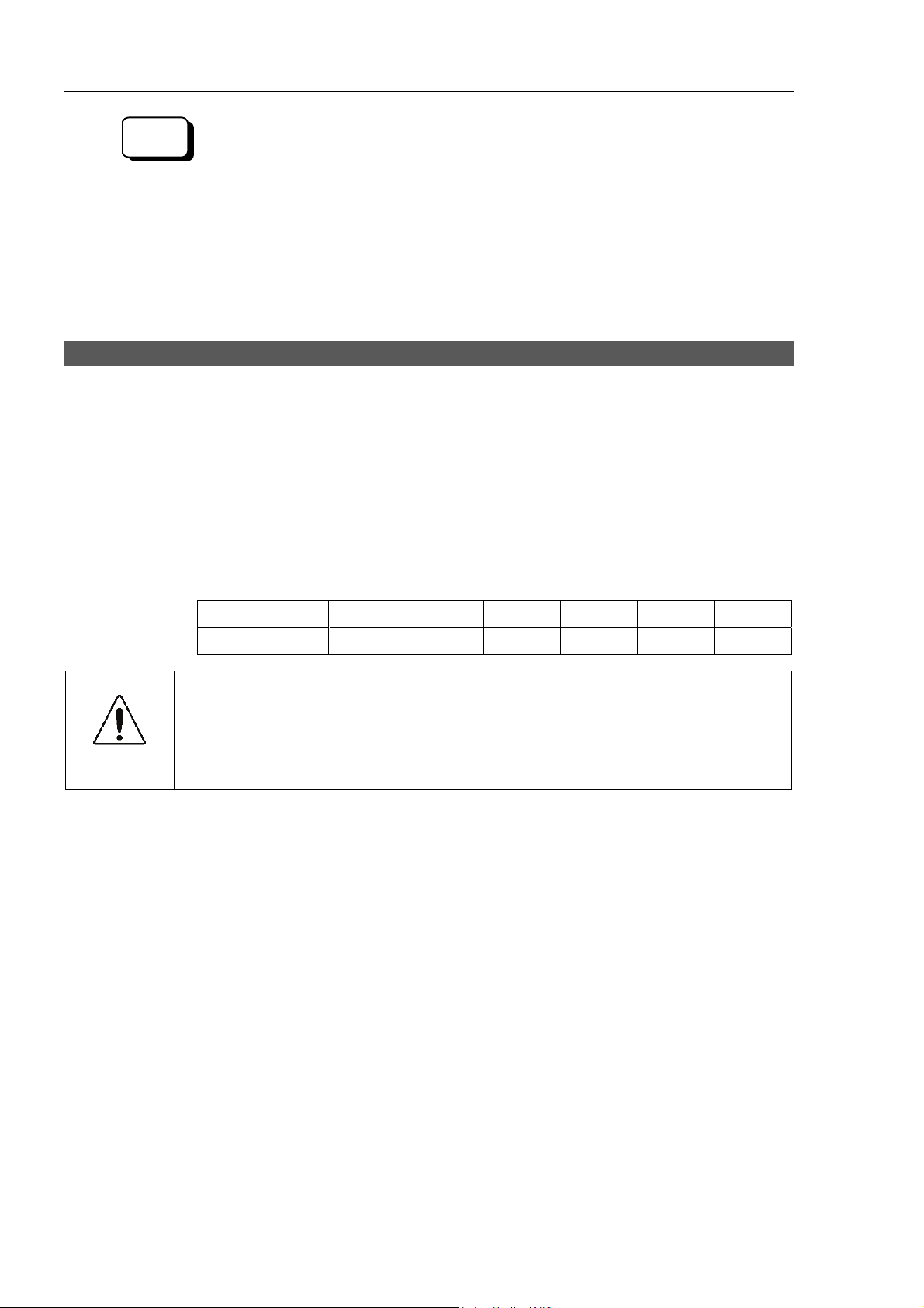
1.7 Manipulator Labels
The following labels are attached around the locations of the Manipulator where specific
dangers exist.
Be sure to comply with descriptions and warnings on the labels to operate and maintain
the Manipulator safely.
Do not tear, damage, or remove the labels. Use meticulous care when handling those
parts or units to which the following labels are attached as well as the nearby areas:
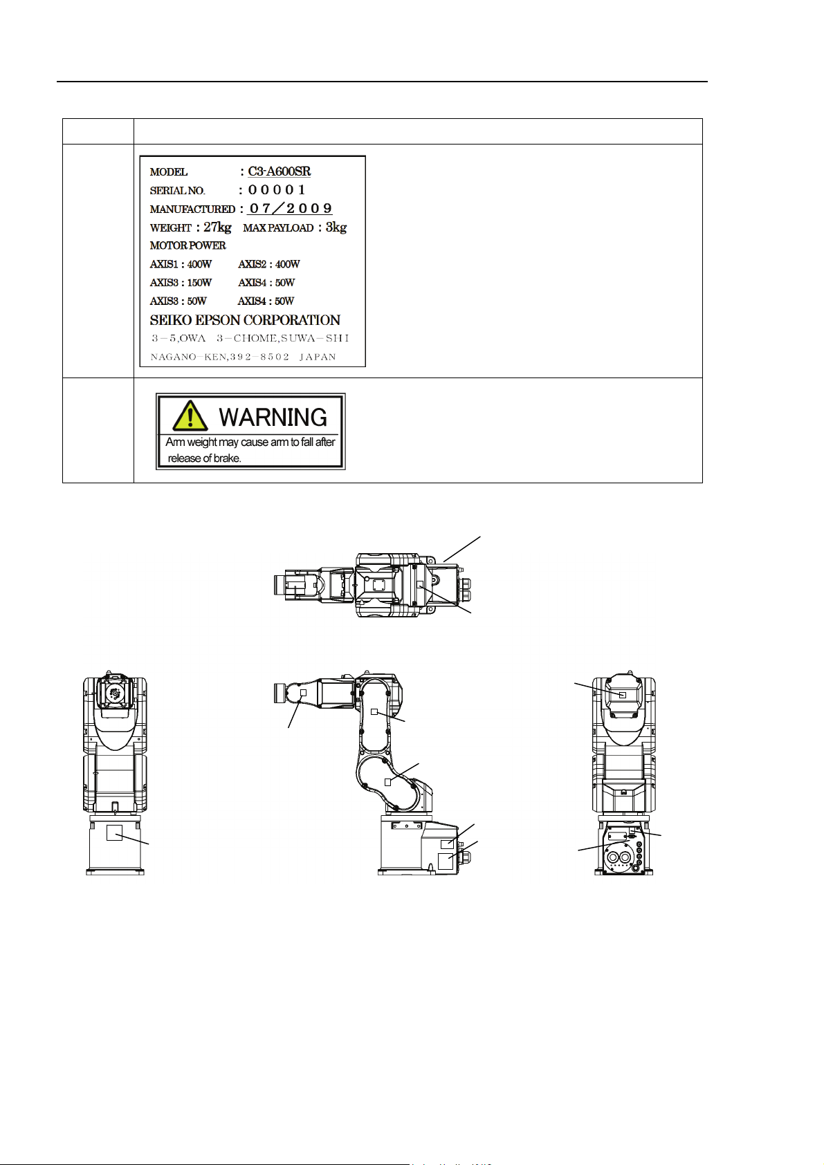
Location Label NOTE
Hazardous voltage exists while the Manipulator is ON.
(1)
(2)
To avoid electric shock, do not touch any internal electric
parts.
Only authorized personnel should perform sling work and
operate a crane and a forklift.
When these operations are performed by unauthorized
personnel, it is extremely hazardous and may result in
serious bodily injury and/or severe equipment damage to
the robot system.
(3)
(4)
(5)
C3 Rev.4 9
Page 22
Setup & Operation 1. Safety
Location Label NOTE
(6)
(7)
Location of Labels
Be careful of the arm falling / rotation while the brake
release button is being pressed.
* This label is on the Brake Release Box (Option).
(6)
(1)
Top V i e w
Front View
(3)
(1)
(1)
(1)
Lateral View
(4)
(2)
(1)
(5)
Back View
(1)
10 C3 Rev.4
Page 23
2. Specifications
2.1 Features of Manipulators
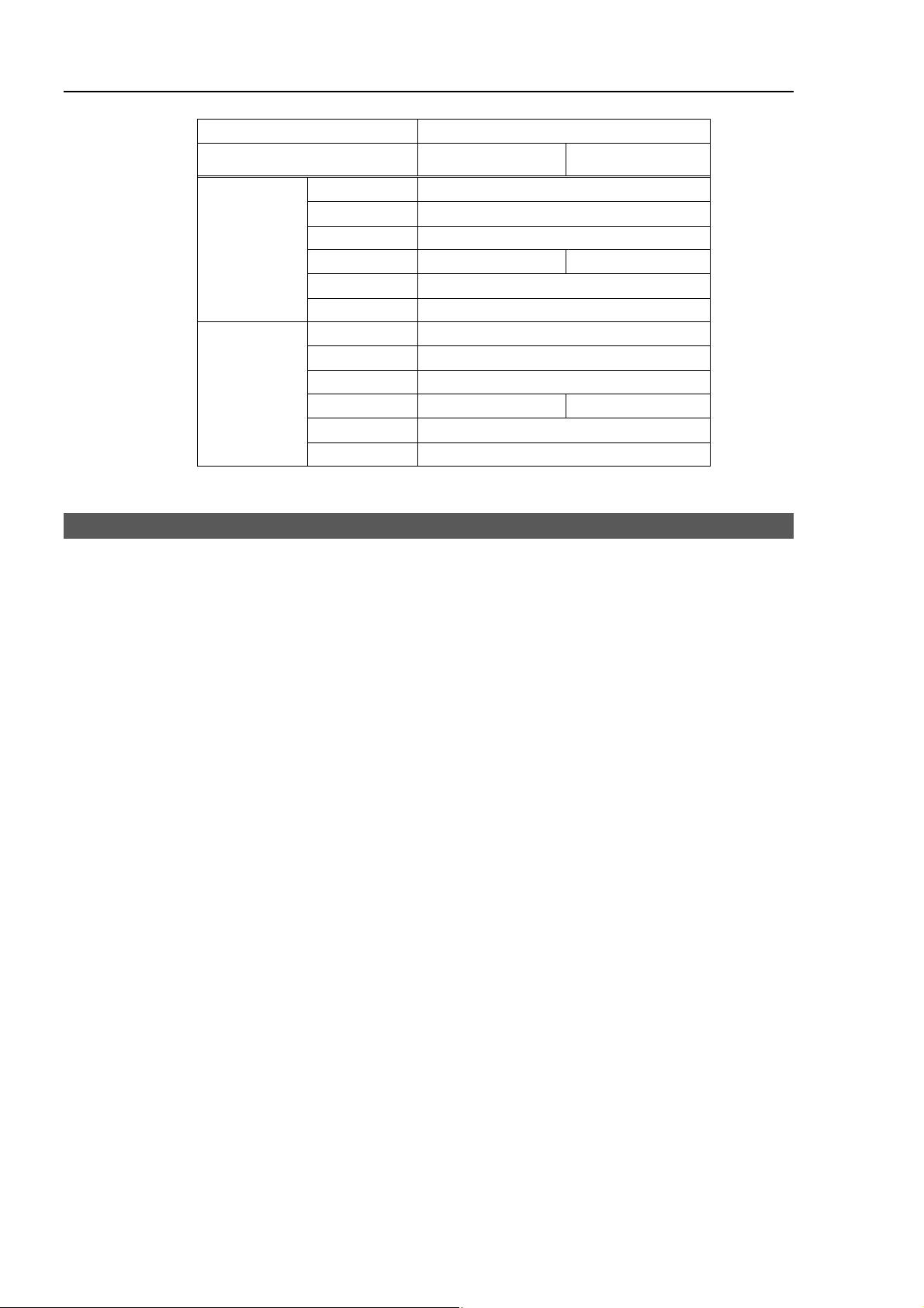
Speed & Accuracy
Increases productivity with the balanced performance of best in class speed and
accuracy
Average cycle time (300 mm) 0.39 second (Speed 100 / Accel 100)
0.37 second (Speed 120 / Accel 120)
Repeatability ± 0.02 mm
Slim Body
High space efficiency
Manipulator volume only 1/44 of its motion range
Small elbow area (Joint #3) half of current model
Less interference with peripherals, walls and ceiling permits more compact
installation
Skillful Wrist
Setup & Operation 2. Specifications
Compact wrist (Joint #5) with wide motion range enables smooth movement and the
ability to work from many angles
Minimal interference with surroundings improves flexibility in hand design
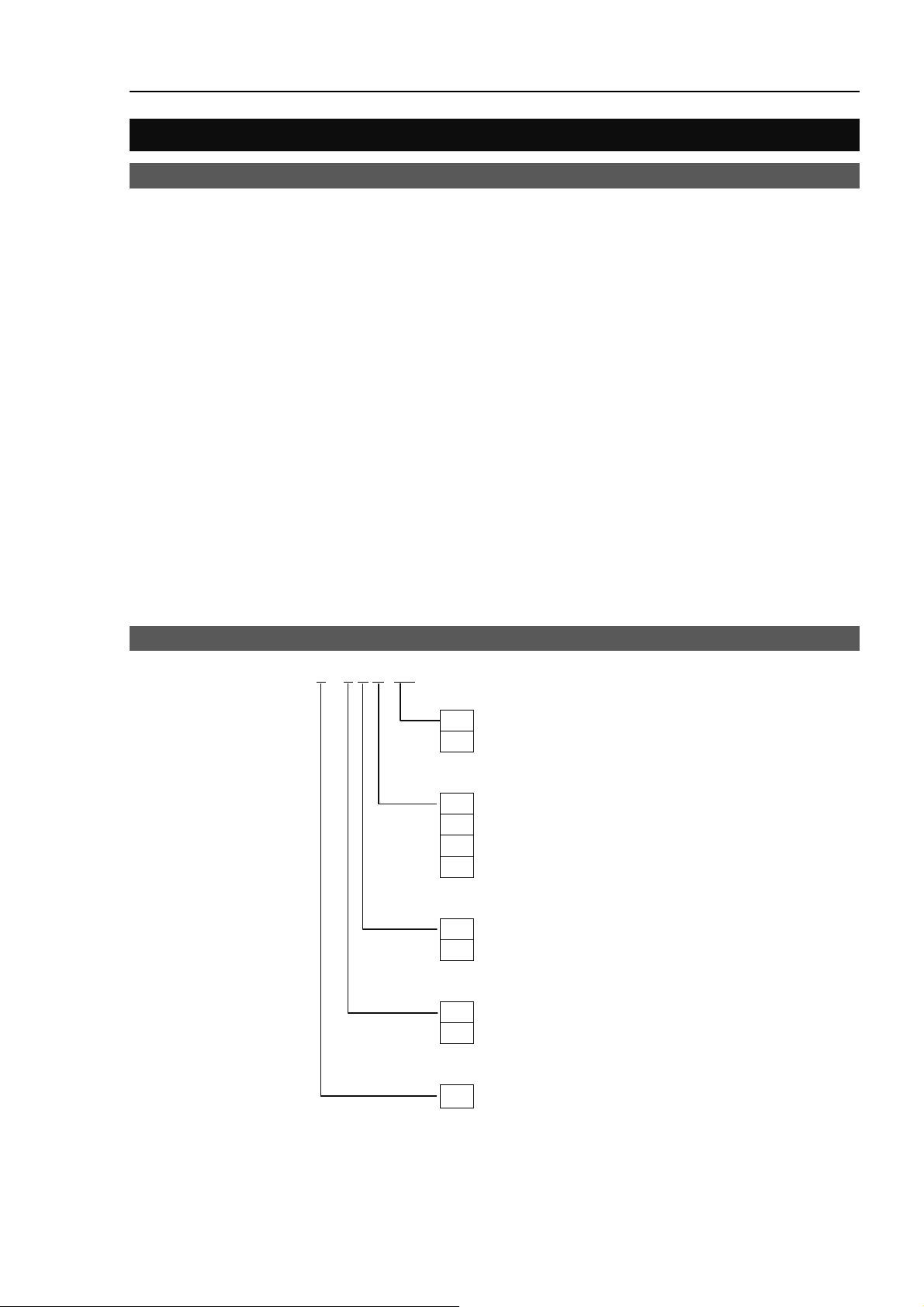
2.2 Model Number
C3 – A 6 0 0 S R -UL
NOTE
For the Wall / Skewed mounting types, brakes are equipped on all joints.
)
UL specification
UL : UL compliant
□
: Non UL compliant
Type
□
: Table Top mounting
W : Wall mounting
R : Ceiling mounting
A : Skewed mounting
Environment
S : Standard model
C : Cleanroom model
Brake equipment
0 : Standard : Brakes on Joint #2, #3, #5
1 : Option : Brakes on all joints
Arm length
6 : 600 mm
C3 Rev.4 11
Page 24
Setup & Operation 2. Specifications
−
A
A
r
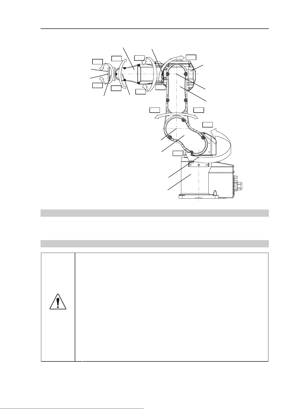
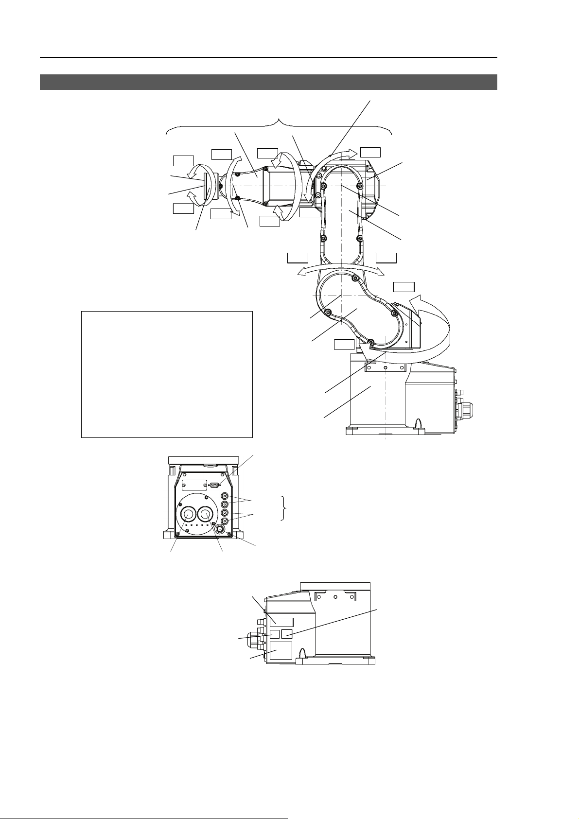
2.3 Part Names and Motion Range of Each Arm
J6−
Arm #6
Joint #6
J6+
Arm #5
Upper Arm (Arms #3 to #6)
Arm #4
J5+
J5−
Joint #5
Joint #4
J4−
J4+
J3
LED Lamp
This lamp lights up
while the motors are ON.
J3+
rm #3
Joint #3
J2+J2−
J1+
rm #2
Joint Motion
Joint #1 : The whole Manipulator revolves.
Joint #2 : The lower arm swings.
Joint #3 : The upper arm swing s.
Joint #4 : The wrist revolves.
Joint #5 : The wrist swings.
Joint #6 : The hand rotates.
Signal cable
(only for UL specification)
Power cable
MT label
(only for custom
specification)
UR label
Joint #2
Arm #1
(Lower Arm)
Joint #1
Base
User cable connecto
(9-pin D-sub connector)
White
Black
Standard-model / Clean-room type
Fitting for ø4 mm pneumatic tube
Cover Exhaust port
For ø8 mm pneumatic tube
J1−
CE label
(only for CE specification)
Signature label
(Serial No. of Manipu lator)
NOTE
)
When the LED lamp is lighting or the controller power is on, the current is being applied
to the manipulator. Performing any work with the power ON is extremely hazardous and
it may result in electric shock and/or improper function of the robot system. Make sure
to turn OFF the controller power before the maintenance work.
12 C3 Rev.4
Page 25
Setup & Operation 2. Specifications
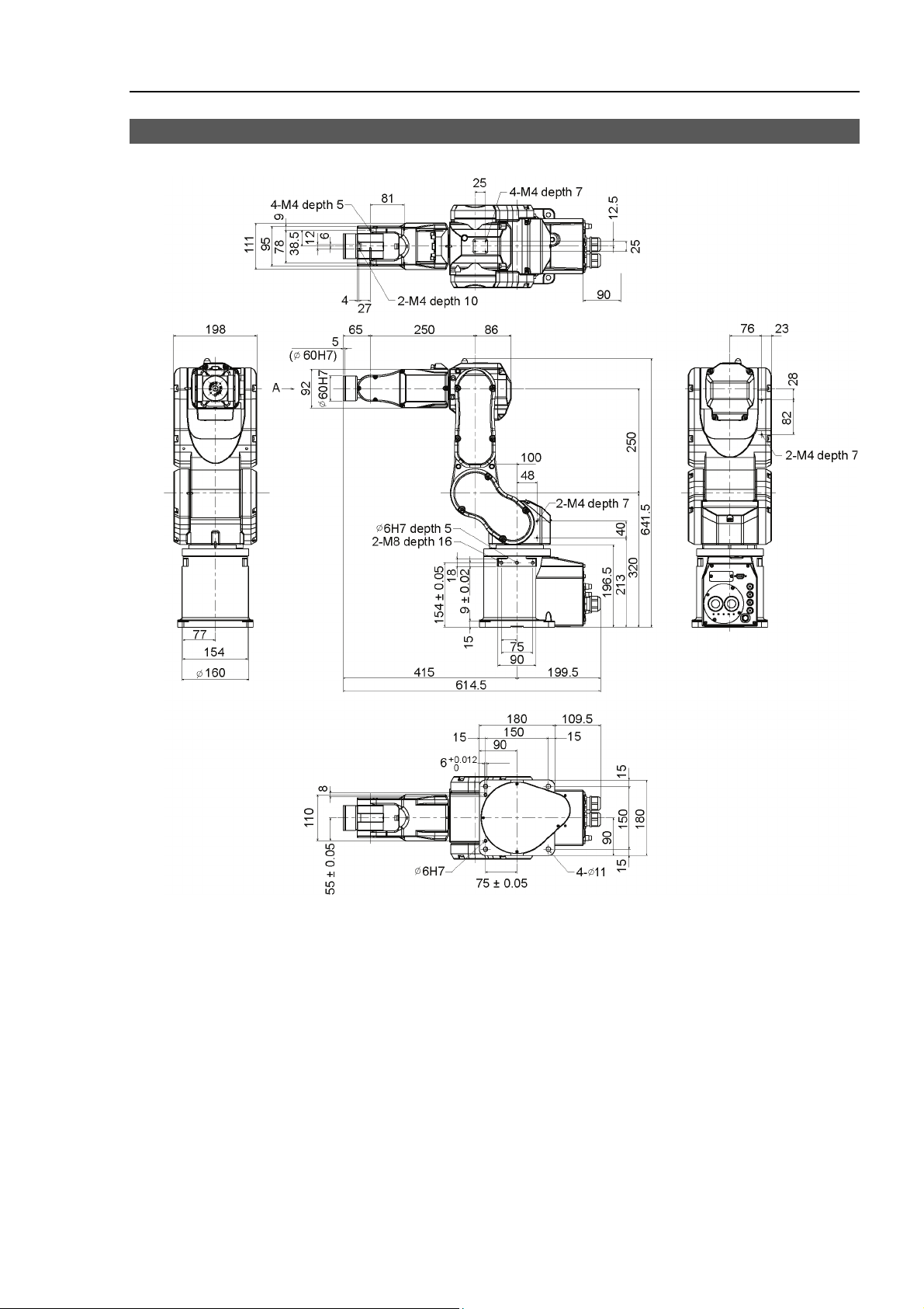
2.4 Outer Dimensions
[Unit: mm]
Space for cables
*1:
*2:
*2:
*2:
Including the lamp
(Tolerance is optimum for ø6H7)
*1: Tolerance in this range
*2: Front and back
C3 Rev.4 13
Page 26
Setup & Operation 2. Specifications
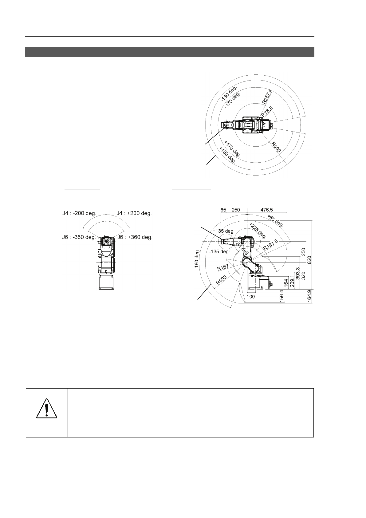
2.5 Standard Motion Range
[Unit: mm]
Motion range of P point*
Top Vi e w
*1
*2
*3
Joint #1
0 pulse position
P point*
Lateral viewFront View
Joints #4, #6
0 pulse position
P point*
Joints #3, #5
0 pulse position
Joint #2
0 pulse position
*5
CAUTION
*4
Motion range of P point*
* P point : Intersection of the rotation centers for Joint #4, #5, and #6
*1 : Joint #1 without mechanical stop (
*2 : P point from top with Joint #3 declining
*3 : P point from top with Joint #3 tilting up
*4 : P point from lateral with Joint #3 declining (51 deg. (Joint #2 center – P point center)
*5 : P point from lateral with Joint #3 tilting up (225 deg. (Joint #2 center – P point center)
Pay attention to the arm pose of the basic arms (Arms #1, #2, and #3) when
±180 deg.)
−51 deg. (Joint #1 center – P point center)
+225 deg. (Joint #1 center – P point center)
operating the Manipulator. Arm #5 moves keeping a constant angle regardless
of the arm pose. Depending on the arm pose of the basic arms, the wrist may
collide with the Manipulator. The collision may cause equipment damage to
and/or malfunction of the Manipulator.
14 C3 Rev.4
Page 27

2.6 Specifications
2.6.1 Specifications table
Item Specification
Model Number
Mounting type
Weight (not include the weight of cables
or shipping jigs)
Driving method All joints
Joint #1
Joint #2
Max. operating
*1
speed
Repeatability Joint #1 ~ #6
Max. motion range
Max. pulse range
Resolution
Motor power consumption
Payload *2
Allowable moment
Joint #3
Joint #4
Joint #5
Joint #6
Joint #1
Joint #2
Joint #3
Joint #4
Joint #5
Joint #6
Joint #1
Joint #2
Joint #3
Joint #4
Joint #5
Joint #6
Joint #1
Joint #2
Joint #3
Joint #4
Joint #5
Joint #6
Joint #1
Joint #2
Joint #3
Joint #4
Joint #5
Joint #6
Rated
Max.
Joint #4
Joint #5
Joint #6
Setup & Operation 2. Specifications
C3
Table Top, Ceiling, Skewed mounting Wall mounting
27 kg (59.5 lb.)
AC servo motor
450 deg/s
450 deg/s
514 deg/s
553 deg/s
553 deg/s
720 deg/s
± 0.02 mm
± 170 deg
(± 180 deg without the mechanical stop)
± 30 deg
− 160 deg ~ + 65 deg
− 51 deg ~ + 225 deg
± 200 deg
± 135 deg
± 360 deg
± 4951609
(± 5242880 without the mechanical stop)
± 873814
− 4660338
+ 1893263
− 1299798
+ 5734400
± 4700057
± 3217222
± 6553600
0.00000429 deg /pulse
0.00000429 deg /pulse
0.00000490 deg /pulse
0.00000531 deg /pulse
0.00000524 deg /pulse
0.00000686 deg /pulse
400 W
400 W
150 W
50 W
50 W
50 W
1 kg
3 kg
5 kg with arm downward positioning
4.41 N·m (0.45 kgf·m)
4.41 N·m (0.45 kgf·m)
2.94 N·m (0.3 kgf·m)
C3 Rev.4 15
Page 28

Setup & Operation 2. Specifications
Item Specification
Allowable moment of
inertia (GD
Installed wire for customer use
Installed pneumatic tube for customer use *4
Environmental
requirements
Equivalent continuous A-weighted sound pressure level
*6
Environment
Applicable Controller
Default values
(Max. setting values)
Safety standard
2
/4) *3
*5
Joint #4
Joint #5
Joint #6
Ambient Temperature
Ambient relative humidity
Vibration
SPEED
ACCEL
SPEEDS
ACCELS
FINE
WEIGHT
*1 In the case of PTP control
0.15 kgxm2
0.15 kgxm2
0.1 kgxm2
9 wires (D-sub)
4 pneumatic tubes,
Allowable pressure: 0.59Mpa
(6 kgf/cm
2
) (89 psi)
5 ~ 40 deg C
20 ~ 80 % (no condensation)
4.9 m⋅s2 (0.5 G) or less
LAeq = 76 dB (A) or under
Standard model
Cleanroom model
*7
& ESD
RC180, RC620
5 (100)
5, 5 (120, 120)
50 (2000)
200 (25000)
10000, 10000, 10000, 10000, 10000, 10000
(65535, 65535, 65535, 65535, 65535, 65535)
1, 0
UL1740 (Third Edition, Dated December 7,2007)
ANSI/RIA R15.06-1999
NFPA 79 (2007 Edition)
CSA/CAN Z434-03 (February 2003)
CE Marking − Machinery Directive,
Low Voltage Directive, EMC Directive
*2 When the setting payload is more than 3 kg and less than or equal to 5 kg, refer to the
section “Restrictions on payload exceeding 3 kg (more than 3 kg and less than or equal
to 5 kg)” in the Setup & Operation 4.3.1 WEIGHT Setting.
*3 In the case where the center of gravity is at the center of each arm. If the center of
gravity is not at the center of each arm, set the eccentric quantity using INERTIA
mmand.
*4 For details of the installed pneumatic tube for customer use, refer to the Setup &
Operation 3.6 User Wires and Pneumatic Tubes.
*5 For details of the environmental requirements, refer to the Setup & Operation 3.1
Environmental Conditions.
*6 Conditions of Manipulator at measurement are as follows:
Operating conditions: Under rated load, 6 arms simultaneous motion, maximum speed,
maximum acceleration, and duty 50%.
Measurement point: 1000 mm apart from the rear of Manipulator
16 C3 Rev.4
Page 29

Setup & Operation 2. Specifications
*7: The exhaust system in the Cleanroom-model Manipulator draws air from the base
interior and arm cover interior.
A crack or other opening in the base unit can cause loss of negative air pressure in the
outer part of the arm, which can cause increased dust emission.
Do not remove the covers.
Seal the exhaust port and the exhaust tube with vinyl tape so that the joint is airtight.
If the exhaust flow is not sufficient, dust particle emission may exceed the specified
maximum level.
Cleanliness level : Class ISO 3 (ISO14644-1)
In previous criteria; Clean Class: 10 or its equivalent
Amount of Dust (0.1 µm diameter or larger) in
28317 cm
of the motion rang: 10 particles or less.)
Exhaust System : Fitting for ø8 mm pneumatic tube
Refer to Setup & Operation: 3.6 User Wires and Pneumatic Tubes.
60 L/min vacuum
Exhaust tube : Polyurethane tube
Outer diameter: ø8 mm (Inner diameter: ø5 to 6 mm)
3
(1cft) sample-air around the center
2.6.2 Option
C3 series has the options below. For details of options, refer to Setup& Operation: 6.
Options.
Brake release unit
Camera plate unit
PS compatible plate
Base side angled fittings
Base side fittings
2.7 How to Set the Model
The Manipulator model for your system has been set before the shipment from the factory.
It is normally not required to change the model when you receive your system.
■
When you need to change the setting of the Manipulator model, be sure to set the
Manipulator model properly. Improper setting of the Manipulator model may
CAUTION
NOTE
)
result in abnormal or no operation of the Manipulator and/or cause safety
problems.
If an MT label is attached to the side of a Manipulator, the Manipulator has custom
specifications. If the Manipulator has custom specifications, the methods for setting the
model may differ from those described below. Please contact us with the number on the
MT label.
The method for setting the Manipulator model depends on the software used.
Refer to the chapter Robot Configuration in the EPSON RC+ User’s Guide.
C3 Rev.4 17
Page 30

Setup & Operation 3. Environment and Installation
3. Environment and Installation
Installation and transportation of robots and robotic equipment shall be performed
by qualified personnel and should conform to all national and local codes.
3.1 Environmental Conditions
A suitable environment is necessary for the robot system to function properly and safely.
Be sure to install the robot system in an environment that meets the following conditions:
Item Conditions
Ambient temperature* 5 deg C ~ 40 deg C
Ambient relative humidity 20 % ~ 80 % (no condensation)
First transient burst noise 2 kV or less (Power supply wire)
1 kV or les (Signal wire)
Electrostatic noise 4 kV or less
Environment · Install indoors.
· Keep away from direct sunlight.
· Keep away from dust, oily smoke, salinity, metal
powder or other contaminants.
· Keep away from flammable or corrosive solvents
and gases.
· Keep away from water.
· Keep away from shock or vibration.
· Keep away from sources of electric noise.
* The ambient temperature conditions are for the Manipulators only. For the Controller
the Manipulators are connected to, refer to the Controller manual.
NOTE
)
When using the Manipulators in inadequate environments that do not meet the above
conditions, please consult your distributor.
Be sure to transport and store the robot system in environments that meet the following
conditions:
Item Conditions
Ambient temperature 0 ~ 45 deg C
Ambient relative humidity 20 ~ 80 %
18 C3 Rev.4
Page 31

Setup & Operation 3. Environment and Installation
3.2 Unpacking, Transportation, and Relocation
Using a cart or similar equipment, transport the Manipulator in the same conditions as it
was delivered. Observe the following when unpacking the Manipulator.
THE INSTALLATION SHALL BE MADE BY QUALIFIED INSTALLATION
PERSONNEL AND SHOULD CONFORM TO ALL NATIONAL AND LOCAL
CODES.
■
Only authorized personnel should perform sling work and operate a crane or
forklift. When these operations are performed by unauthorized personnel, it is
extremely hazardous and may result in serious bodily injury and/or severe
WARNING
equipment damage to the robot system.
■
Stabilize the Manipulator with your hands when hoisting it. Unstable hoisting is
extremely hazardous and may results in serious bodily injury and/or severe
equipment damage to the robot system as the fall of the Manipulator.
■
When removing the anchor bolts, support the Manipulator to prevent falling.
Removing the anchor bolts without supporting the Manipulator may get hands,
fingers, or feet caught as the Manipulator will fall.
CAUTION
■
To carry the Manipulator, have at least 2
people to work on it and secure the
Manipulator to the delivery equipment or
hold it by hand.
Do not hold the bottom of the base (the
screened parts in the figure). Holding
these parts by hand is extremely
hazardous and may cause your hands
and fingers to be caught.
■
Avoid excessive vibration or shock during Manipulator transporting. Excessive
vibration or shock may cause equipment damage to and/or malfunction of the
Manipulator.
During unpacking and relocation avoid applying external force to the arms and motors of
the Manipulator.
When transporting the Manipulator for a long distance, secure it to the delivery equipment
so that the Manipulator cannot fall. If necessary, pack the Manipulator in the same way
as it was delivered.
When condensation occurs on the Manipulator during transport or storage, turn ON the
power only after the condensation dries.
When using the Manipulator for the robot system again after long-term storage, perform a
test run to verify that the Manipulator works properly. Then, operate the Manipulator
thoroughly.
Manipulator weight
: 27 kg (59.5 lb.)
DO NOT hold
the bottom of the
base by hand.
C3 Rev.4 19
Page 32

Setup & Operation 3. Environment and Installation
Relocating
Follow the procedures described below when relocating the Manipulator.
(1) Turn OFF the power for all devices and unplug the power cable connector and signal
cable connector from the controller.
Do not unplug the M/C cable (power cable and signal cable) from the manipulator.
NOTE
Remove the mechanical stops if using them to limit the motion range.
)
For details on the motion range, refer to the Setup & Operation 5.2 Motion Range
Setting by Mechanical Stops.
(2) Unscrew the anchor bolts. Then, remove the Manipulator from the base table.
(3) Position the Manipulator as shown in the
figure. Then, secure the Manipulator to the
delivery equipment or have 2 or more people
to carry the Manipulator.
Recommend : Joint #2 +65 deg.
Joint #3 −51 deg.
Manipulator weight
: 27 kg (59.5 lb.)
Do not hold the bottom of the base (the
screened parts in the figure). Holding these
parts by hand is extremely hazardous and may
cause your hands and fingers to be caught.
DO NOT hold
the bottom of the
base by hand.
Using Eyebolt
Check that the eyebolts are securely fastened before carrying the Manipulator.
After transporting the Manipulator, remove the eyebolts and keep them for future use.
The weight of the Manipulator is approx. 27 kg (59.5 lb). The eyebolts and wire must be
strong enough to withstand the weight.
or more
or less
Holes for eye bolt
2-M6 depth 12.5
Use the wire of
1000 mm or more
to avoid contact
with Manipulator.
If you use the eyebolts to lift up the Manipulator, be sure to use the bifilar wire of 1000
mm-long or more to avoid contact with the Arm #4 side cover.
However, the Manipulator can swing while lifting up even with the appropriate length of
wire, so be sure to handle it with care.
Take extra care if you use the wire of 240 mm-long or more to lift the Manipulator,
because the wire is likely to touch the Arm #4 side cover and break the Manipulator.
20 C3 Rev.4
Page 33

3.3 Mounting Dimensions
Mounting Area
Be sure to have the following space available in addition to the space for mounting the
Manipulator, Controller, and peripheral equipment.
Space for teaching points
Space for maintenance and inspections
Space for cables
NOTE
)
The minimum bend radius of the power cable is 90 mm. When installing the cable, be
sure to maintain sufficient distance from obstacles. In addition, leave enough space for
other cables so that they are not bent forcibly.
Mounting Dimensions [Unit: mm]
Setup & Operation 3. Environment and Installation
(Reference through hole)
Space for cable
(Mounting hole)
C3 Rev.4 21
Page 34

Setup & Operation 3. Environment and Installation
3.4 Installation
THE INSTALLATION SHALL BE MADE BY QUALIFIED INSTALLATION
PERSONNEL AND SHOULD CONFORM TO ALL NATIONAL AND LOCAL
CODES.
■
To ensure safety, a safeguard must be installed for the robot system. For details
on the safeguard, refer to the Installation and Design Precautions in the Safety
chapter of the EPSON RC+ User’s Guide.
■
Install the Manipulator at a location with sufficient space so that a tool or a work
piece on the end effector does not reach a wall or a safeguard when the
Manipulator extends its arm fully while holding a work piece. Installing the
Manipulator at a location with insufficient space is extremely hazardous and may
result in serious bodily injury and/or severe equipment damage to the robot
system as a tool or a work piece may collide with a wall and a safeguard.
■
Anchor the Manipulator before turning ON the power to or operating the
WARNING
Manipulator. Turning ON the power to or operating the Manipulator that is not
anchored is extremely hazardous and may result in serious bodily injury and/or
severe equipment damage to the robot system as the Manipulator may fall down.
CAUTION
■
Before installing and operating the Manipulator, make sure that all parts of the
Manipulator are in place and have no external defects. Missing or defective
parts may cause improper operation of the Manipulator. Improper operation of
the Manipulator is extremely hazardous and may result in serious bodily injury
and/or severe equipment damage to the robot system.
■
The robot system must be installed to avoid interference with buildings,
structures, utilities, other machines and equipment that may create a trapping
hazard or pinch points.
Mounting bolt
There are 4 threaded holes for the Manipulator base. Use M8 mounting bolts
conforming to the strength, ISO898-1 property class: 12.9. For the dimensions, refer to
Setup & Operation 3.3 Mounting Dimensions.
Base table
A base table for anchoring the Manipulator is not supplied. Please make or obtain the
base table for your Manipulator. The shape and size of the base table will differ
depending on the use of the robot system. For your reference, we list some basic
Manipulator table requirements here.
The base table must not only be able to bear the weight of the Manipulator but also be able
to withstand the dynamic movement of the Manipulator when it operates at maximum
acceleration. Ensure that there is enough strength on the base table by attaching
reinforcing materials such as crossbeams.
22 C3 Rev.4
Page 35

Setup & Operation 3. Environment and Installation
The torque and reaction force produced by the movement of the Manipulator are as
follows:
Max. Horizontal rotating torque : 500 N·m
Max. Horizontal reaction force : 800 N
Max. Vertical rotating torque : 600 N·m
Max. Vertical reaction force : 2500 N
The plate for the Manipulator mounting face should be 30 mm thick or more and made of
steel to reduce vibration. The surface roughness of the steel plate should be 25 μm or
less.
The base table must be secured on the floor to prevent it from moving.
The Manipulator must be installed horizontally.
When using a leveler to adjust the height of the base table, use a screw with M16 diameter
or more.
Connector
If you are passing cables through the holes on the base table, see the figures below.
[unit : mm]
95
47
26
53
18
NOTE
)
Power Cable
Connector
M/C Cables
Signal Cable
Connector
Do not remove the M/C cables from the Manipulator.
For environmental conditions regarding space when placing the Controller on the base
table, refer to the Controller manual.
Cleanroom-model Manipulator
For the Cleanroom-model, follow the steps below before the installation.
(1) Unpack it outside of the clean room.
(2) Secure the Manipulator to delivery equipment such as a pallet with bolts so that the
Manipulator does not fall.
(3) Wipe off the dust on the Manipulator with a little alcohol or distilled water on a
lint-free cloth.
(4) Carry the Manipulator in the clean room.
(5) Secure the Manipulator to the base table.
(6) Connect an exhaust tube (ø 8 mm) to the exhaust port.
C3 Rev.4 23
Page 36

Setup & Operation 3. Environment and Installation
3.5 Connecting the Cables
■
Before performing any replacement procedure, turn OFF the Controller and related
equipment, and then pull out the power plug from the power source.
Performing any replacement procedure with the power ON is extremely hazardous
and may result in electric shock and/or malfunction of the robot system.
■
Be sure to connect the AC power cable to a power receptacle. DO NOT connect
it directly to a factory power source. To shut off power to the robot system, pull
out the power plug from the power source. Performing any work while
connecting the AC power cable to a factory power source is extremely hazardous
and may result in electric shock and/or malfunction of the robot system.
■
Be sure to connect the cables properly. Do not allow unnecessary strain on the
cables. (Do not put heavy objects on the cables. Do not bend or pull the
WARNING
cables forcibly.) The unnecessary strain on the cables may result in damage to
the cables, disconnection, and/or contact failure. Damaged cables,
disconnection, or contact failure is extremely hazardous and may result in electric
shock and/or improper function of the robot system.
CAUTION
■
Before wiring, turn OFF the Controller and related equipment, and then pull up a
warning sign (e.g. DO NOT TURN ON THE POWER.). Wiring with the power
ON is extremely hazardous and may result in electric shock and/or malfunction of
the robot system.
■
Grounding the manipulator is done by connecting with the controller. Ensure that
the controller is grounded and the cables are correctly connected. If the ground
wire is improperly connected to ground, it may result in the fire or electric shock.
■
When connecting the Manipulator and the Controller, make sure that the serial
numbers on each equipment match. Improper connection between the
Manipulator and Controller may not only cause improper function of the robot
system but also safety problems. The connection method varies with the
Controller used. For details on the connection, refer to the Controller manual.
■
Only authorized or certified personnel should be allowed to perform wiring.
Wiring by unauthorized or uncertified personnel may result in bodily injury and/or
malfunction of the robot system.
Cleanroom-model Manipulator
For the Cleanroom-model, an exhaust system is necessary. For details, refer to Setup &
Operation: 2.6 Specifications.
Connect
Connect the power
connector and signal
connector of the M/C
cables to the Controller.
24 C3 Rev.4
M/C power cable
M/C signal
Page 37

Setup & Operation 3. Environment and Installation
r
3.6 User Wires and Pneumatic Tubes
■
Only authorized or certified personnel should be allowed to perform wiring.
CAUTION
Wiring by unauthorized or uncertified personnel may result in bodily injury and/or
malfunction of the robot system.
User electrical wires and pneumatic tubes are contained in the cable unit.
Electrical Wires
Rated Voltage
Allowable
Current
Wires
AC/DC30 V 1 A 24 0.211 mm2
Maker Standard
9 pin
Suitable Connector JAE
Clamp Hood JAE
Pins with the same number, indicated on the connectors on both ends of the cables, are
connected.
Nominal Sectional
Area
Outer Diameter Note
ø8.3±0.3 mm
Shielded
DE-9PF-N (Solder type)
DE-C8-J9-F2-1R (Connector setscrew: #4-40 NC)
Pneumatic Tubes
Max. Usable Pneumatic Pressure Pneumatic Tubes Outer Diameter × Inner Diameter
0.59 MPa (6 kgf/cm2 : 86 psi)
4 ø4 mm × ø2.5 mm
Tubes with the same number, indicated in details of A and B, are connected.
B
Detail of “B”
No.1 No.2 No.3 No.4
Detail of “A”
A
User cable connector
(9-pin D-sub connector)
User cable connecto
(9-pin D-sub connector)
No.1 : White
No.2 : White
No.3 : Black
No.4 : Black
Standard-model : Cover
Clean-room type : Exhaust port
( For ø8 mm pneumatic tube)
Fitting for
ø4 mm
pneumatic tube
We prepare the part that can be mounted to the position shown in “Detail of B”.
C3 Rev.4 25
Page 38

Setup & Operation 3. Environment and Installation
One Touch Fittings Kit (Set of four: M5-ø4 mm one touch fittings for tubes)
Straight Elbow
User Connector kit (Single: 9 pins D-sub connector)
26 C3 Rev.4
Page 39

3.7 Checking the Basic orientation
After parts have been replaced (motors, reduction gear units, belts, etc.), the Manipulator
cannot operate properly because a mismatch exists between the origin stored in each motor
and its corresponding origin stored in the Controller.
The process of aligning the two origins is called “Calibration”.
At shipment, the following basic orientation is configured as origin.
After all setting is done, go through an origin return run and make sure the manipulator
moves to the right basic orientation.
To make the manipulator return to origin, select the [Tool]-[Robot Manager]-[Control
Panel] and click the <Home> button.
If the manipulator cannot be in the basic orientation after the origin return run (not like as
the figure below), refer to Maintenance 16. Calibration to calibrate the manipulator.
Setup & Operation 3. Environment and Installation
Basic orientation
C3 Rev.4 27
Page 40

Setup & Operation 4. End Effectors
4. End Effectors
4.1 Attaching an End Effector
Create an end effector for your Manipulator that will attach to Arm #6. Before attaching
the end effector to the end of Arm #6, observe these guidelines.
■
If you use an end effector equipped with a gripper or chuck, connect wires and/or
pneumatic tubes properly so that the gripper does not release the work piece
when the power to the robot system is turned OFF. Improper connection of the
wires and/or pneumatic tubes may damage the robot system and/or work piece
CAUTION
as the work piece is released when the Emergency Stop switch is pressed.
I/O outputs are configured at the factory so that they are automatically shut off (0)
by power disconnection, the Emergency Stop switch, or the safety features of the
robot system.
Wrist Flange
Toleranc e in this range
A
Detail of “A”
Arm #6
Attach an end effector to the end of the Arm #6 using an M4 bolt.
Layouts
When you operate the Manipulator with an end effector, the end effector may interfere
with the Manipulator because of the outer diameter of the end effector, the size of the work
piece, or the position of the arms. When designing your system layout, pay close
attention to the interference area of the end effector.
Standard specification (Brakes on Joints #2, #3, #5)
When the end effector is mounted, the joint may rotate by the hand weight or inertia in
Emergency Stop status. The end effector may contact the manipulator body depending
on the diameter of end effector, size of part, or arm position. Be careful about the area of
interference of the end effector for the system layout.
Compatibility with PS series
To mount the end effector used in the PS series to the C3 series, we prepare the option –
PS Compatible Plate. For details of the option, refer to Setup & Operation: 6. Options.
28 C3 Rev.4
Page 41

4.2 Attaching Camera and Valves
Decks are equipped to Arms #3 and #5 to enable the easy installation of air valve.
Deck
Setup & Operation 4. End Effectors
Deck
Rotation Center
of the Upper
Space for cable
[Unit: mm]
For details of the payload exceeding 3 kg, refer to the section “Restriction on payload
exceeding 3 kg (more than 3 kg and less than or equal to 5 kg)” in the Setup & Operation
4.3.1 WEIGHT Setting.
To mount the camera, the camera plate unit is necessary.
We prepare the option – Camera Plate Unit. For details of the option, refer to Setup &
Operation: 6. Options.
C3 Rev.4 29
Page 42

Setup & Operation 4. End Effectors
4.3 WEIGHT and INERTIA Settings
The WEIGHT and INERTIA commands are for setting the load parameters of the
Manipulator. These settings optimize the Manipulator motion.
WEIGHT Setting
The WEIGHT command is for setting the load weight. The more the load weight
increases, the more the speed and acceleration/deceleration for the Manipulator movement
are reduced.
INERTIA Setting
The INERTIA command is for setting the moment of inertia and the eccentricity of the
load. The more the moment of inertia increases, the more the acceleration and
deceleration of the Arm #6 are reduced. The more the eccentricity increases, the more
the acceleration and deceleration for the Manipulator movement are reduced.
To ensure optimum Manipulator performance, it is important to make sure that the load
(weight of the end effector and work piece) and moment of inertia of the load are within
the maximum rating for the Manipulator, and that Arm #6 does not become eccentric.
If the load or moment of inertia exceed the ratings or if the load becomes eccentric, follow
the steps in the Setup & Operation 4.3.1 WEIGHT Setting and 4.3.2 INERTIA Setting, to
set parameters.
Setting parameters makes the operation of the Manipulator optimal, reduces vibration to
shorten the operating time, and improves the capacity for larger loads. In addition, it
reduces persistent vibration produced when the moment of inertia of the end effector and
work piece is bigger.
The allowable weight for C3 Manipulators is up to 3 kg (5 kg*). However, the moment
and the moment of inertia should also be considered due to limitations for these factors.
If force is applied to the Manipulator instead of the weight, force on the Arms #4, #5, and
#6 should be within the values shown in the table “Allowable Moment and Moment of
Inertia for C3 Manipulators”.
* When the load of the Manipulator is more than 3 kg and less than or equal to 5 kg,
refer to the section “Restriction on payload exceeding 3 kg (more than 3 kg and less
than or equal to 5 kg)” in the Setup & Operation 4.3.1 WEIGHT Setting.
Allowable Moment and Moment of Inertia for C3 Manipulators
Arm Allowable Moment
*1
GD2/4 Allowable Moment of Inertia
#4 4.41 N·m (0.45 kgf·m) 0.15 kg·m2
#5 *2
4.41 N·m (0.45 kgf·m) 0.15 kg·m
2
#6 2.94 N·m (0.3 kgf·m) 0.1 kg·m2
*1 Gravitational unit
*2 The allowable moment and allowable moment of inertia of Arm #5 are calculated by
the distance from the Arm #5 rotation center (a + 65 mm). (Refer to the figure in the
“Critical Location of the Load on C3 Manipulators”).
30 C3 Rev.4
Page 43

Setup & Operation 4. End Effectors
Critical Location of the Load on C3 Manipulators
Position of
Load’s Center
of Gravity
Arm #J6
Rotation
Center
Flange
Arm #J5
Rotation Center
[Unit: mm]
Rotation Center
Distance from the Arm #J6
Distance from the Flange
When calculating the critical location of the load on the Arm #5 using the allowable
moment and allowable moment of inertia, the calculated value represents a distance from
the Arm #5 rotation center, not the distance from the flange. Therefore, to get a value of
the critical location of the load on Arm #5, subtract 65 (mm) from the calculated distance
from the Arm #5 rotation center as shown the example below.
Example: Calculate the critical location of the load on the Arm #5 (c) when a 2.5 kg load is
on the Arm #6 rotation center line (b = 0).
Allowable Moment of the Arm #5 (N·m) / Load (kg)
= Distance from the Arm #5 rotation center (m)
4.41 (N·m) / 9.8 / 2.5 (kg) = 0.18 → 0.18 (m) = 180 (mm)
c (mm) = Distance from the Arm #5 rotation center (mm) − 65 (mm)
c = 180 (mm) − 65 (mm) = 115 (mm)
C3 Rev.4 31
Page 44

Setup & Operation 4. End Effectors
Moment
A moment is a necessary torque (holding torque) to counteract the gravity affecting the
load.
Design an end effector so that the eccentric quantity at the position where the load is
attached is within the allowable moment.
A maximum torque (T) is calculated by the following formula.
T = m (kg) × L (m) × g (m/s
m: Weight of load (kg)
L: Eccentric quantity of load (m)
g: Gravitational acceleration (m/s
Max. Eccentric Quantity of Load
(Distance between the joint rotation center and the load’s center of gravity)
Axis WEIGHT 1 kg WEIGHT 2 kg WEIGHT 3 kg
#4
#5
200 mm 200 mm 150 mm
200 mm 200 mm 150 mm
#6 200 mm
(The maximum eccentric quantity of load is restricted to 200 mm or less.)
4.3.1 WEIGHT Setting
■
Set the total weight of the end effector and the work piece to 3 kg or less.
The C3 Manipulators can operate without limitations on the condition that the
load of the Manipulator should be 3 kg or less. When the payload of the
Manipulator is more than 3 kg and less than or equal to 5 kg, refer to the section
“Restrictions on payload exceeding 3 kg (more than 3 kg and less than or equal
CAUTION
to 5 kg)” in the later part of this section for details.
Always set the Weight parameters of the WEIGHT command according to the
load. Setting a value that is smaller than the actual load may cause errors,
excessive shock, insufficient function of the Manipulator, and/or shorten the life
cycle of parts/mechanisms.
2
)
2
)
150 mm 100 mm
L
Joint Rotation Center
T
The acceptable weight capacity (end effector and work piece) for C3 Manipulators is 1 kg
nominal rating and 3 (5) kg maximum*. When the load (weight of the end effector and
work piece) exceeds the rating, change the setting of the Weight parameter.
After the setting of the Weight parameter is changed, the maximum
acceleration/deceleration and speed of the robot system corresponding to the Weight
parameter is set automatically.
* When the payload of the Manipulator is more than 3 kg and less than or equal to 5 kg,
refer to the section “Restrictions on payload exceeding 3 kg (more than 3 kg and less
than or equal to 5 kg)” in the later part of this section for details.
32 C3 Rev.4
Page 45

Setup & Operation 4. End Effectors
Setting method of Weight parameters
The method for setting Weight parameter varies with the software used.
EPSON
RC+
EPSON RC+ 5.0 (RC180) / EPSON RC+ 6.0 (RC620)
Enter into the [Weight:] text box on the [Weight] panel ([Tools]-[Robot Manager]).
You may also execute the Weight command from [Command Window].
Load on the Manipulators
The Manipulator can load valves or any other devices onto the following three points.
Top View
Load on the
Fore – end of Arm #6
Arm #5 Deck
Arm #3 Deck
Deck detailed
approx.
approx.
approx.
approx.
Arm #5 Deck Arm #3 Deck
[Unit: mm]
When you attach the equipment to the decks on the upper arm, convert its weight into
equivalent weight assuming that the equipment is attached to the end of the Arm #6.
Then, this equivalent weight added to the load will be a Weight parameter.
C3 Rev.4 33
Page 46

Setup & Operation 4. End Effectors
w
Calculate the Weight parameter by following the formula below and enter the value.
Weight Parameter Formula
Weight parameter = M
Mw
: Load on the fore-end of Arm #6 (kg)
W
: Equivalent weight of the Arm #3 deck (kg)
a
W
: Equivalent weight of the Arm #5 deck (kg)
b
W
= Ma (La)²/ (L)²
a
= Mb (Lb)²/ (L)²
W
b
M
: Weight of the air valve on the Arm #3 deck
a
M
: Weight of the camera on the Arm #5 deck
b
L
: Length of the upper arm (315 mm)
L
: Distance between the Joint #3 and the center of gravity of
a
the air valve on the Arm #3 deck (mm)
L
: Distance between the Joint #3 and the center of gravity
b
of the camera on the Arm #5deck (mm)
+ Wa + Wb
w
M
<Example> The fore-end of Arm #6 is 315 mm (L) away from the Joint #3.
Load on the fore-end of Arm #6 is 1 kg (M
Load on the Arm #3 deck is 1.5 kg (M
The deck is 0 mm (L
) away from Joint #3.
a
Load on the Arm #5 deck is 0.5 kg (M
The deck is 280 mm (L
) away from the Joint #3.
b
).
w
).
a
).
b
=1.5 × 02/3152=0
W
a
=0.5 × 2802/3152=0.395 → 0.4(round up)
W
b
M
+ W
w
=1 + 0 + 0.4=1.4
+ W
a
b
Enter “1.4” for the Weight parameter.
34 C3 Rev.4
Page 47

Setup & Operation 4. End Effectors
Automatic speed setting by Weight parameter
Acceleration
/ Deceleration
Speed
Weight Parameter
* The percentage in the graph is based on the speed at rated weight (1 kg) as 100%.
* When the payload of the Manipulator is more than 3 kg and less than or equal to 5 kg,
refer to the section “Restrictions on payload exceeding 3 kg (more than 3 kg and less
than or equal to 5 kg)” in the later part of this section for details.
Restrictions on payload exceeding 3 kg
(more than 3 kg and less than or equal to 5 kg)
Although the maximum payload of the C3 Manipulator is 3 kg, you can increase up to 5
kg when you restrict the arm pose range of Arm #5 with arm downward positioning.
When the load is over 3 kg, the Arm #5 orientation must be within the angle indicated in
the following graph.
1
The graph shows the relation of the load weight and Arm #5 angle limit (A
vertical direction (direction of gravity). Note that the heavier load Arm #6 holds, the
smaller the angle limit becomes.
When the manipulator operates vertically to the operating surface, the limit of Arm #5 is
2
equivalent to the limit of operating angle (A
).
In addition, for the eccentric load, the angle limit is an angle of the line joining the center
of load and Arm #5 rotation axis with the vertical direction (B).
) measured in
The eccentric quantity of load should be within the allowable moment and the allowable
moment of inertia of Arms #4, #5, and #6.
C3 Rev.4 35
Page 48

Setup & Operation 4. End Effectors
1
2
Relation of load weight and Arm #5 angle limit
Arm #5 Angle Limit
Arm #5 rotation axis
Arm #5
Arm #6
Load on Arm #6 End
Arm #4
Vertical direction
Load on
Arm 6 end
: Arm #5 angle
A
from vertical direction
Operating surface
A
Plane
: Angle of operating
surface form plane
Arm #5
Arm #6
Angle limit for eccentric load Relation of Arm #5 angle and operating surface
Vertical direction
Arm #5 rotation axis
Gravity
Load on
Arm #6 end
B
36 C3 Rev.4
Page 49

y
4.3.2 INERTIA Setting
Moment of Inertia and the INERTIA Setting
The moment of inertia is defined as “the ratio of the torque applied to a rigid body and its
resistance to motion”. This value is typically referred to as “the moment of inertia”,
“inertia”, or “GD
attached to the Arm #6, the moment of inertia of load must be considered.
■
The moment of inertia of load (weight of the end effector and work piece) must be
0.1 kg·m
2
of inertia exceeding 0.1 kg·m
CAUTION
Always set the moment of inertia (INERTIA) parameter according to the moment
of inertia. Setting a value that is smaller than the actual moment of inertia may
cause errors, excessive shock, insufficient function of the Manipulator, and/or
shorten the life cycle of parts/mechanisms.
The acceptable moment of inertia of load in C3 Manipulator is 0.1 kgxm2 nominal rating
and 0.1 kgxm
the setting of the moment of inertia using the INERTIA command. After the setting has
been changed, the maximum acceleration/deceleration speed of Arm #6 responding to
“moment of inertia” is set automatically.
Moment of inertia of load on Arm #6
The moment of inertia of load (weight of the end effector and work piece) on Arm #6 can
be set by the “moment of inertia (INERTIA)” parameter of the INERTIA command.
The method for setting the parameter varies with the software used.
EPSON
RC+
EPSON RC+ 5.0 (RC180) / EPSON RC+ 6.0 (RC620)
Enter into the [Load inertia:] text box on the [Inertia] panel ([Tools]–[Robot Manager]).
You may also execute the Inertia command from [Command Window].
Setup & Operation 4. End Effectors
2
”. When the Manipulator operates with objects such as an end effector
or less. The C3 Manipulators are not designed to work with moment
2
.
2
maximum. When the moment of inertia of load exceeds the rating, change
Eccentric Quantity and the INERTIA Setting
■
The eccentric quantity of load (weight of the end effector and work piece) must be
200 mm or less. The C3 Manipulators are not designed to work with eccentric
quantity exceeding 200 mm.
.
CAUTION
Always set the eccentric quantity parameter according to the eccentric quantit
Setting a value that is smaller than the actual eccentric quantity may cause
errors, excessive shock, insufficient function of the Manipulator, and/or shorten
the life cycle of parts/mechanisms.
The acceptable eccentric quantity of load in C3 Manipulators is 30 mm nominal rating and
200 mm maximum. When the eccentric quantity of load exceeds the rating, change the
setting of eccentric quantity parameter using the INERTIA command. After the setting
has been changed, the maximum acceleration/deceleration speed of Manipulator
corresponding to “eccentric quantity” is set automatically.
C3 Rev.4 37
Page 50

Setup & Operation 4. End Effectors
Rotation Center
a
Flange
b
Position of Load’s Center of Gravity
a, b = Eccentric Quantity
(200 mm or less)
To set the parameter, enter
the larger value of “a” or “b”.
Eccentric Quantity
Eccentric quantity of load on Arm #6
The eccentric quantity of load (weight of the end effector and work piece) on Arm #6 can
be set by the “eccentric quantity” parameter of the INERTIA command.
Enter the larger value of “a” or “b” in the figure above to the [Eccentricity] text box.
The method for setting the parameter varies with the software used.
EPSON
RC+
EPSON RC+ 5.0 (RC180) / EPSON RC+ 6.0 (RC620)
Enter into the [Eccentricity:] text box on the [Inertia] panel ([Tools]–[Robot Manager]).
You may also execute the Inertia command from [Command Window].
Automatic acceleration/deceleration setting by INERTIA (eccentric quantity)
Eccentric Quantity
* The percentage in the graph is based on the acceleration/ deceleration at rated eccentricity (30 mm)
as 100%.
INERTIA (eccentric quantity) is affected by the load setting. When you configure the
load setting, refer to Setup & Operation 4.3: WEIGHT and INERTIA Settings and
determine it carefully.
38
C3 Rev.4
Page 51

Setup & Operation 4. End Effectors
Calculating the Moment of Inertia
Refer to the following examples of formulas to calculate the moment of inertia of load
(end effector with work piece).
The moment of inertia of the entire load is calculated by the sum of each part (a), (b), and
(c).
Rotation Center
End Effector (a)
Work Piece (b)
Whole Moment
of Inertia
Moment of Inertia
=
of End Effector (a)
Moment of Inertia
+
of Work Piece (b)
Work Piece (c)
Moment of Inertia
+
of Work Piece (c)
The methods for calculating the moment of inertia for (a), (b), and (c) are shown on this
page or the next page. Find the whole moment of inertia using the basic formulas on the
next page.
C3 Rev.4 39
Page 52

Setup & Operation 4. End Effectors
(a) Moment of inertia of a rectangular parallelepiped
Rectangular Parallelepiped’s Center of Gravity Rotation Center
Weight = m
L
h
(b) Moment of inertia of a cylinder
Cylinder’s Center of Gravity
Rotation Center
r
Weight = m
L
(c) Moment of inertia of a sphere
Rotation Center
b
Sphere’s Center of Gravity
m+ m × L
m+ m × L
2
b
r
2
+ h2
12
2
2
2
40
2
5
2
+ m × L2
Weight = m
L
r
mr
C3 Rev.4
Page 53

Setup & Operation 4. End Effectors
4.4 Precautions for Auto Acceleration/Deceleration
The speed and acceleration/deceleration of the Manipulator motion are automatically
optimized according to the values of WEIGHT and INERTIA and the Manipulator’s
postures.
WEIGHT Setting
The speed and acceleration/deceleration of the Manipulator are controlled according to the
load weight set by the WEIGHT command.
The more the load weight increases, the more the speed and acceleration/deceleration are
reduced to prevent residual vibration.
INERTIA Setting
The acceleration/deceleration of Arm #6 are controlled according to the moment of inertia
set by the INERTIA command. The acceleration/deceleration of the whole Manipulator
are controlled according to the eccentricity set by the INERTIA command. The more the
moment of inertia and eccentricity of the load increase, the more the
acceleration/deceleration are reduced.
Auto Acceleration/Deceleration According to Manipulator’s Posture
The acceleration/deceleration are controlled according to the Manipulator’s posture.
When the Manipulator extends its arms or when the movement of the Manipulator
produces vibration frequently, the acceleration/deceleration are reduced.
Set appropriate values for WEIGHT and INERTIA so that the Manipulator operation is
optimized.
C3 Rev.4 41
Page 54

Setup & Operation 5. Motion Range
5. Motion Range
■
When setting up the motion range for safety, both the pulse range and
WARNING
mechanical stops must always be set at the same time. Failure to set both of
them together may cause serious safety problems.
The motion range is preset at the factory as explained in the Setup & Operation 2.5
Standard Motion Range. This is the maximum motion range of the Manipulator.
There are three methods for setting the motion range described as follows:
1. Setting by pulse range (for all arms)
2. Setting by mechanical stops
3. Setting the Cartesian (rectangular) range in the X, Y coordinate system of the
Manipulator
Rectangular Range Setting
Mechanical
Stop
When the motion range is changed due to layout efficiency or safety, follow the
descriptions in 5.1 to 5.4 to set the range.
Motion Range
Pulse Range
5.1 Motion Range Setting by Pulse Range (for All Arms)
Pulses are the basic unit of Manipulator motion. The motion range of the Manipulator is
controlled by the pulse range between the pulse lower limit and upper limit of each axis.
Pulse values are read from the encoder output of the servo motor.
The pulse range must be set inside of the mechanical stop range.
■
Do not set and/or use the Arm #4 with pulse range beyond the maximum value.
The Arm #4 does not have a mechanical stop. The used of Arm #4 in motion
CAUTION
exceeding the maximum pulse range may cause inner wiring damage to and/or
malfunction of the Manipulator.
Mechanical
Stop
You can check the inner wiring torsion by
removing the Arm #3 cover.
Arm #3 cover
42 C3 Rev.4
Page 55

t
NOTE
)
EPSON
RC+
Once the Manipulator receives an operating command, it checks whether the target
position specified by the command is within the pulse range before operating. If the
target position is out of the set pulse range, an error occurs and the Manipulator does not
move.
EPSON RC+ 5.0 (RC180) / EPSON RC+ 6.0 (RC620)
The pulse range can be set on the [Range] panel shown by selecting the [Tools]-[Robo
manager].
You may also execute the Range command from the [Command Window].
5.1.1 Max. Pulse Range of Arm #1
Counterclockwise pulse values are positive (+) and clockwise pulse values are negative
(-).
Setup & Operation 5. Motion Range
(without mechanical stop)
Arm #1 0 pulse position
5.1.2 Max. Pulse Range of Arm #2
Counterclockwise pulse values are positive (+) and clockwise pulse values are negative
(-).
Arm #2
0 pulse position
(without mechanical stop)
C3 Rev.4 43
Page 56

Setup & Operation 5. Motion Range
5.1.3 Max. Pulse Range of Arm #3
Counterclockwise pulse values are positive (+) and clockwise pulse values are negative
(-).
Arm #3 0 pulse position
5.1.4 Max. Pulse Range of Arm #4
From the angle of arm end, clockwise pulse values are positive (+) and counterclockwise
pulse values are negative (-).
Arm #4
0 pulse position
CAUTION
■
Do not set and/or use the Arm #4 with pulse range beyond the maximum value.
The Arm #4 does not have a mechanical stop. The used of Arm #4 in motion
exceeding the maximum pulse range may cause inner wiring damage to and/or
malfunction of the Manipulator.
You can check the inner wiring torsion by
removing the Arm #3 head cover.
Arm #3 head cover
44 C3 Rev.4
Page 57

5.1.5 Max. Pulse Range of Arm #5
Counterclockwise pulse values are positive (+) and clockwise pulse values are negative
(-).
Arm #5 0 pulse position
5.1.6 Max. Pulse Range of Arm #6
From the angle of arm end, clockwise pulse values are positive (+) and counterclockwise
pulse values are negative (-).
Arm #6
0 pulse position
Setup & Operation 5. Motion Range
5.2 Motion Range Setting by Mechanical Stops
Mechanical stops physically limit the absolute area that the Manipulator can move.
Be sure to turn OFF the Controller in advance.
Bolts are not provided, arrange for them by yourself.
Use a bolt conforming to the strength specified by ISO-898-1, property class: 12.9.
Re-specify the pulse range after changing the position of the mechanical stop.
For details on the pulse range setting, refer to the Setup & Operation 5.1 Motion Range
Setting by Pulse Range (for All Arms).
Be sure to set the pulse range without exceeding the pulse values corresponding to the
mechanical stop’s setting angles.
C3 Rev.4 45
Page 58

Setup & Operation 5. Motion Range
5.2.1 Motion Range Setting of Arm #1
There are threaded holes corresponding to each angle on the
Manipulator.
Normally a mechanical stop is equipped in [ b ].
[ a ] and [ c ] limit the one side of motion range.
a
If the motion range of Arm #1 is ±180 deg, remove the bolts
below.
M8×15 hexagon socket head cap bolt
Tightening torque 3720 N·cm (380 kgf·cm)
Angle (deg.)
Pulse (pulse)
Bolt
a b c
−125 ±170 ±180
−3640889 ±4951609 ±5242880 −3640889
Applied
5.2.2 Motion Range Setting of Arm #2
There are threaded holes corresponding to each angle on
the Manipulator.
Normally there is no mechanical stop equipped.
(−160 deg. - +65 deg.)
[ d ] and [ e ] limit the one side of motion range.
M10×15 hexagon socket head cap bolt
Tightening torque 7350 N·cm (750 kgf·cm)
Applied (Normal) Not applied
d
b
c
+125
Applied
e
Angle (deg.)
Pulse (pulse)
Bolt
d e - -
−143
−4165177
Applied Applied
5.2.3 Motion Range Setting of Arm #3
There are threaded holes corresponding to each angle on
the Manipulator.
Normally mechanical stops are equipped to [ g ] and [ h ].
(+225 deg. - −51 deg.)
M8×12 hexagon socket head cap bolt
Tightening torque 3720 N·cm (380 kgf·cm)
Angle (deg.)
Pulse (pulse)
Bolt
f i g h
+201
+5122731
Applied Applied
+48
+1398102
−27
−688128
−160
−4660338
Not applied
(Normal)
g
h
+225
+5734400
Applied
(Normal)
+65
+1893263
Not applied
(Normal)
f
i
−51
−1299798
Applied
(Normal)
46 C3 Rev.4
Page 59

Setup & Operation 5. Motion Range
5.3 Restriction of Manipulator Operation by Joint Angle Combination
To prevent the arms of the Manipulator from interfering each other, the Manipulator
operation is restricted in the specified motion range according to the joint angle
combination of the Arm #1, #2, and #3.
The Manipulator operation is restricted and the Manipulator stops when the joint angles of
the Arm are within the gray areas in the following figure.
Combination of Joint #1 and #2
Joint #2 Angle
Joint #1 Angle
Combination of Joint #2 and #3
Joint #3 Angle
Joint #2 Angle
The restriction to Manipulator operation is enabled:
- During CP motion command execution
- You attempt to execute the motion command for moving the Manipulator to a target
point (or pose) in the specified motion range.
The restriction to the Manipulator operation is disabled:
- The Arms of the Manipulator momentarily go through the specified motion range
during the PTP motion command execution even though the joint angles of the Arms
are in the gray areas of the figures above.
C3 Rev.4 47
Page 60

Setup & Operation 5. Motion Range
t
5.4 Coordinate System
The origin point is located where the Manipulator base intersects with the rotation axis of
Joint #1.
For details on the coordinate system, refer to the EPSON RC+ Users Guide manual.
Table Top mounting Ceiling mounting Wall mounting Skewed mounting
+Y
+X
+Z
+X
+Z
+Z
+X
+Y
+Y
+X
+Y
+Z
+Z
+X
+Y
20 deg.
+Y
5.5 Setting the Cartesian (Rectangular) Range in the XY Coordinate System of the Manipulator
The Cartesian (rectangular) range in the XY coordinate system of the Manipulator is
specified by the limited Manipulator operation area and the XYLIM setting.
The limited Manipulator operation area is defined so that the end effector does not
interfere with the rear side of the Manipulator. The XYLIM setting is that you can set the
upper and lower limits of the X and Y coordinates.
The limited Manipulator operation area and XYLIM setting apply only to the software.
Therefore, these settings do not change the physical range. The maximum physical range
is based on the position of the mechanical stops.
These settings are disabled during a joint jogging operation. Therefore, be careful not to
allow the end effector to collide with the Manipulator or peripheral equipment.
The method for changing the XYLIM setting varies with the software used.
EPSON
RC+
EPSON RC+ 5.0 (RC180) / EPSON RC+ 6.0 (RC620)
Set the XYLIM setting on the [XYZ Limits] panel shown by selecting the [Tools]-[Robo
manager].
You may also execute the XYLim command from the [Command Window].
48 C3 Rev.4
Page 61

6. Options
The C3 series has the options below.
6.1 Brake Release Unit
6.2 Camera Mounting Plate
6.3 PS Compatible Plate
6.4 Base Side Angled Fittings
6.5 Base Side Fittings
6.1 Brake Release Unit
With the electromagnetic brake is ON (such as in Emergency Stop status), you cannot
move the Arms #2, #3, #5 by hand. If the all joints have a brake, all arms don’t move.
You can move Arms by hand using the brake release unit while the controller power is
OFF or right after unpacking.
■
Before connecting/disconnecting the connector of Brake release unit, be sure to
WARNING
check the powers of the controller and break release unit are OFF.
Otherwise, it leads to the electrical shock or breakdown.
Setup & Operation 6. Option
CAUTION
■
Release a brake for each joint one by one. If you need to release some brakes
at a time, take a great care. Because when some joints are released at a time,
the arms may fall to unintended directions. This is extremely dangerous and
may break the manipulator or catch your hand, fingers.
■
Take care of the arm downward motion when the brake is released.
While you are pressing the brake release switch, the arm moves downward by its
own weight. This is extremely dangerous and may break the manipulator or
catch your hand, fingers.
Width 180 mm
Depth 150 mm
Height 87 mm
Weight (Cables are not included.) 1.7 kg
Cable to the Manipulator 2 m
Power cable length 2 m
Power cable (US) 100 V specification
Power cable (EU) 200 V specification
A
View from A
Power switch
C3 Rev.4 49
Power cable
Power lamp
Arm switches
Page 62

Setup & Operation 6. Option
Precautions for use
■
After the brake release unit is disconnected, be sure to connect the external short
connector. Otherwise, you cannot release the brakes.
■
Keep the external short connector.
Otherwise you cannot release the brakes.
■
If you turn ON the brake release unit while the brake release switch is being
pressed, an unintended arm may move downward.
Before turning ON the brake release unit, make sure that the brake release
switch is not pressed.
■
If you turn ON the brake release unit without the connector, it may lead to the
short for the male pin used in the connector.
Before turning ON the brake release unit, make sure that the connector is
connected.
■
When you purchased several C3 series manipulators and use the brake release
unit in the manipulator without the connection cable, you need to change the
connection cable inside the manipulator.
To skip this switching work, purchase the cable set for the brake release unit.
If you purchased the manipulator and connection cable together, the cable has
been installed to the manipulator before shipment.
For additional external short connector or connection cable, please contact us.
CAUTION
NOTE
)
50 C3 Rev.4
Page 63

(2)
(3)
How to connect the connection cable
If you purchased the manipulator and connection cable together, the cable has been
installed to the manipulator before shipment. This procedure is not necessary.
Setup & Operation 6. Option
(1) Turn OFF the controller.
(2) Remove the hiding plate.
2-M4×8
(3) Open the connector plate.
4-M4×8
For details, refer to Maintenance: 3.
Covers.
(4)
Pass the cable through the hole below
the hiding plate from the outside.
Connect the connection cable to the
connector plate.
2-M4×8
(5)
Take out the connector of internal cable
SW1.
Hiding plate
2-M4×8
Connector plate
4-M4×8
Connector plate
Connection cable
(6)
(7)
(8)
(9)
Disconnect the internal short connector.
Keep the short connector to the inside
Internal short connector
of base or somewhere not to lose.
Connect the connection cable and
internal cable SW1.
Connection
cable
Mount the connector plate. Be careful not to catch the cables.
4-M4×8
If the brake release unit is not used,
mount the external short connector.
To prevent the external short connector
from falling off, secure the two screws
External short connector
included with the connector.
Connector SW1
C3 Rev.4 51
Page 64

Setup & Operation 6. Option
Mount the brake release unit
(1)
(2)
(3)
Turn OFF the controller.
Remove the external short connector.
Connect the brake release unit to the
connector of the connection cable.
Remove the brake release unit
External short connector
Connector of the
connection cable
(1)
(2)
(3)
(4)
Turn OFF the brake release unit.
Remove the power cable of the brake release unit.
Disconnect the brake release unit from the connector of connection cable.
Connect the external short connector to the connector of connection cable.
52 C3 Rev.4
Page 65

How to use the brake release unit
■
Be careful of the arm downward motion while you release the brakes.
The arm will move downward by its own weight while you are pressing a brake
release switch. This is extremely dangerous and may break the manipulator or
catch your hand, fingers.
■
CAUTION
If the arm you released the brake moves strange or slower than normal, stop the
motion promptly and contact us. The brake release unit is possibly broken and
if you keep operating the manipulator, it may lead to the brake of the
manipulator or you will be caught by the hand or fingers.
Setup & Operation 6. Option
(2) Power switch
(1)
(2)
(3)
(4)
(5)
NOTE
)
Disconnect the external short connector.
Plug the power cable into the brake release unit.
Plug the power cable into the power supply plug.
Turn ON the brake release unit.
When the brake release unit is enabled, the power lamp lights up.
Press the arm switch J1 ~ J6 you want to move and then move the arm.
Press the switch again, then the brake will be released.
The brake will be enabled by pressing the switch once again.
Move the arm the brake is released by two persons or more (one presses the switch
and one moves the arm). The arm can be very heavy and needs the significant force
to move.
(1) Power cable
(3) Arm switches connector lock(2) Power lamp
C3 Rev.4 53
Page 66

Setup & Operation 6. Option
A
r
6.2 Camera Plate Unit
To mount a camera to the C3 series manipulator, you need to mount the camera plate unit
first.
Appearance of arm end with camera
Camera
Camera plate unit
Parts included unit
A Camera adapter plate 1
B Camera mid plate 1
C Camera base plate 1
D Hexagon socket head screws
M4×12
E hexagon socket head screws
M4×20
F Plain washer for M4
(small washer)
To mount the camera plate unit
(1) Mount the camera base plate to the manipulator.
2-M4 × 20 + Plain washer for M4 (small washer)
(2) Mount the camera mid plate to the base plate.
6
: Camera adapter plate
2
2
D
B: Camera mid plate
C: Camera base plate
Mounting holes of
camera base plate
D
D
E
F
2-M4 × 12
(3) Mount the camera to the camera adapter plate.
(4) Mount the camera adapter plate and camera to the camera mid plate.
(5) Secure the cables at the position where they will not interfere with the manipulato
NOTE
)
NOTE
)
NOTE
)
The motion range and dimension of the manipulator with the camera installed may
vary depending on the mounting hole of camera mid plate. The details are
described in the table below.
According to the camera, the available mounting hole of adapter plate will be
different. The details are described below.
4-M4 × 12
motion.
When securing the cables, check if the cables bend radius is big enough and the
cables are not rubbing against each other while the manipulator moves. Otherwise,
the cables will be disconnected.
54 C3 Rev.4
Page 67

Setup & Operation 6. Option
Dimension of the camera plate unit
3-M4 through hole
(for securing cables)
4-M4 depth 5
(for securing cables)
Camera
4-M4 depth 8 * same hole on opposite side
(for securing cables)
Dimensions X and Y will change depending on the position of camera mid plate and
camera size. Refer to the table below for the values.
Camera mid plate
The camera mid plate uses the mounting holes
A ~ D .
By using the different mounting holes, it can
be mounted to the camera base plate in the
different four positions.
Camera adapter plate
Each camera uses the different mounting holes.
Sony XC-ES30, HR50, HR70 : 1, 2, 4
Matrox Iris : 1, 2, 3, 5
JAI (Pulnix) CV-A1 : 6, 7
1
3
4
2
5
6
7
Mounting example
Using the mounting hole A Using the mounting hole C
E.g.) Camera: XC-ES30
C3 Rev.4 55
Page 68

Setup & Operation 6. Option
Camera vs. Joint #5 motion range (reference values)
The Joint #5 motion range varies depending on the mounting position of camera mid plate
and the camera you are using.
The table below shows the motion range (reference values) based on the available cameras
for this option and the mounting positions of the camera mid plate. The values in the
table may vary depending on how to secure the cables.
By changing the Y position, you can extend the distance from the end effector mounting
surface to the camera. Also, you can attach the larger end effector. However, be careful
about the Joint #5 motion range that will be limited in this case.
(° = degree)
JAI (Pulnix) CV-A1
Sony XC-ES30, HR50, HR70
Matrox Iris −135° ~ +45° −135° ~ +30° −135° ~ +15° −135° ~ +10° 83 mm
Y
A B C D X
−135° ~ +60° −135° ~ +50° −135° ~ +35° −135° ~ +25° 72.5 mm
A B C D
57 mm 37 mm 17 mm 7 mm
Direction of the Joint #5 motion
56 C3 Rev.4
Page 69

6.3 PS Compatible Plate
Using the PS compatible plate, you can mount the end effector used in the PS series to the
C3 series.
Parts included Unit
A PS compatible plate 1
B Dowel pin (M3 hole on one side) 1
C Hexagon socket head screw M4×12
Setup & Operation 6. Option
4
Dimensions of PS-compatible plate
Spot faced hole for M4
(at 90 ° pitch)
H7 depth 12
4-M4 depth 12
(at 90 ° pitch)
Insert dowel pin here
C: Hexagon socket head screw
4-M4×12
A: PS-compatible plate
B: Dowel pin (M3 hole on one side)
(° = degree)
To mount the PS compatible plate
(1)
Align the hole on the arm end flange (ø12H7) to the projection on the PS compatible
plate (ø12h7).
(2) Insert the dowel pin from the PS compatible plate side and position the arm and PS
compatible plate. One side of the dowel pin has the M3 screw hole and you can
adjust the depth using M3.
NOTE
)
If you move the manipulator with the dowel pin inserted, the dowel pin will fall out.
Even so you want to move the manipulator, you need to secure the dowel pin with
glue.
(3) Secure the PS compatible plate with 4 hexagon socket head screws.
4-M4 × 12
C3 Rev.4 57
Page 70

Setup & Operation 6. Option
A
6.4 Base Side Angled Fittings
Using the base side angled fittings to the C3 series manipulator base, you can mount the
manipulator in skewed position. The motion range expands with this mounting type
more than the normal ceiling mounting.
Mounting image using the base side angled fittings
For details of the mounting and precautions, refer to Setup & Operation: 3. Environment
and Installation.
Parts included Unit
A Base side angled plate (Left side) 1
B Base side angled plate (Right side) 1
C Base side plate (for Skewed mounting type) 2
D Pin 6
E Hexagon socket head screw M8 × 25 4
F Hexagon socket head screw M8 × 30 4
D
E
F F
B
D
CC
D
E
58 C3 Rev.4
Page 71

Setup & Operation 6. Option
To mount the base side angled fittings
(1) Drive pins to the base side plate (for Skewed mounting type).
Protruding part of pins is approx. 2 ~ 5 mm.
(2) Drive pins to the base side angled plate (left & right sides).
Protruding part of pins is approx. 2 ~ 5 mm.
(3)
(4)
Create a base side angled fittings.
Fit the pins of the plate for Skewed mounting type in the step
(1) with the holes on the plate in the step (2) and secure with
the screws.
Hexagon socket head screw M8 × 30
Mount the base side angled fittings to the both sides of manipulator base.
Fit the pins drove in the step (2) with the holes on the base. Secure the fittings by
pressing it to the indicated direction in the figure below.
Left & Right side Hexagon socket heat screw 2- M8 × 25
Two pi ns
Protruding part
2mm~5mm
Pin at each side
Protruding part
2mm~5mm
Right side
NOTE
)
Base side
angled fittings
2-M8×25
The shape of base side angled fittings is different for left and for right. Be sure to
mount the correct fittings.
Otherwise, the motion range of Arm #2 is limited in the backside.
C3 Rev.4 59
Page 72

Setup & Operation 6. Option
Dimension of the manipulator with the base side angled fitting is installed
(Prepared hole ø8.5)
(Tolerance is ø6H 7)
Base plate thickness*
40mm or less
Position of
base plate
* Base plate thickness
NOTE
)
We recommend that the base plate thickness is between 30 mm and 40mm. If the
thickness is more than 40 mm, the manipulator may contact the base plate when Arm #1
rotates, depending on the center cut dimension in the base plate.
The base plate securing the manipulator is prepared by users. The torque value and
reaction force generated in the manipulator motions are described in Setup & Operation:
3.4 Installation.
60 C3 Rev.4
Page 73

A
A
6.5 Base Side Fittings
Using the base side fittings to the C3 manipulator base, you can mount the manipulator in
the place where limits the mounting height or use the open room for the base.
Mounting image using the base side fittings
For the information on how to mount and precautions, refer to Setup & Operation: 3.
Environment and Installation.
Parts included Unit
A Base side plate 2
B Pin 2
Hexagon socket head
C
screw M8 × 60
C
4
Setup & Operation 6. Option
B
C
To mount the base side plate
(1) Drive the pins to the base side plate.
Protruding part of pins is approx. 2 ~ 5 mm.
(2)
Mount the base side plate with the pins driven to the both sides of the base.
Fit the pins with the holes and secure the base side plate by pressing it from above to
the base fixing part.
(With the steps above, the both surfaces of base side fittings can be stable.)
Base fixing
part
2-M8×60
Pin protruding part
2. Press toward this face from above
2mm~5mm
1. Insert pins into
the holes
C3 Rev.4 61
Page 74

Setup & Operation 6. Option
Dimension of the manipulator with the base side fittings installed
2-M10
(Prepared hole ø8.5)
2-M10
(Prepared hole ø8.5)
62 C3 Rev.4
Page 75

Setup & Operation 6. Option
←
f
f
f
Mounting example
Available screws
Size Recommended length
A M8 30 mm or more
B M10 15 mm + Base Plate or more
NOTE
)
Table Top mounting
The base side plate has a M10 screw hole. You can secure with a M10
screw or M8 screw by using a M10 prepared screw of ø8.5 to make a M8
screw hole on the mounting surface.
A: Securing from above
To secure from above, use the screw A in the table above.
When you install the manipulator for practical use, you need to insert the
screws in the right/left side from the same direction (above or below).
B: Secures
rom below
A: Secures
rom above
A: Secures
rom below
B: Secures
from above
Base Plate
(Floor)
Ceiling mounting
A: Secures
from above
← Base plate
(Ceiling)
A: Secures
from below
B: Secures
from above
B: Secures
from below
C3 Rev.4 63
Page 76

Setup & Operation 6. Option
64 C3 Rev.4
Page 77

Maintenance
This volume contains maintenance procedures with safety
precautions for C3 series Manipulators.
Page 78

Page 79

1. Safety Maintenance
Please read this chapter, this manual, and other relevant manuals carefully to understand
safe maintenance procedures before performing any routine maintenance.
Only authorized personnel who have taken safety training should be allowed to
maintain the robot system.
Safety training is the program for industrial robot operators that follows the laws
and regulations of each nation.
The personnel who have taken safety training acquire knowledge of industrial
robots (operations, teaching, etc.), knowledge of inspections, and knowledge of
related rules/regulations.
The personnel who have completed the robot system-training and maintenancetraining classes held by the manufacturer, dealer, or locally-incorporated
company are allowed to maintain the robot system.
Do not remove any parts that are not covered in this manual. Follow the
■
maintenance procedure strictly as described in this manual. Improper removal
of parts or improper maintenance may not only cause improper function of the
robot system but also serious safety problems.
Maintenance 1. Safety Maintenance
WARNING
WARNING
■
Keep away from the Manipulator while the power is ON if you have not taken the
training courses. Do not enter the operating area while the power is ON.
Entering the operating area with the power ON is extremely hazardous and may
cause serious safety problems as the Manipulator may move even it seems to be
stopped.
■
When you check the operation of the Manipulator after replacing parts, be sure to
check it while you are outside of the safeguarded area. Checking the operation
of the Manipulator while you are inside of the safeguarded area may cause
serious safety problems as the Manipulator may move unexpectedly.
■
Before operating the robot system, make sure that both the Emergency Stop
switches and safeguard switch function properly. Operating the robot system
when the switches do not function properly is extremely hazardous and may
result in serious bodily injury and/or serious damage to the robot system as the
switches cannot fulfill their intended functions in an emergency.
■
To shut off power to the robot system, pull out the power plug from the power
source. Be sure to connect the AC power cable to a power receptacle. DO
NOT connect it directly to a factory power source.
■
Before performing any replacement procedure, turn OFF the Controller and
related equipment, and then pull out the power plug from the power source.
Performing any replacement procedure with the power ON is extremely
hazardous and may result in electric shock and/or malfunction of the robot
system.
C3 Rev.4 67
Page 80

Maintenance 1. Safety Maintenance
Be sure to connect the cables properly. Do not allow unnecessary strain on the
■
cables. (Do not put heavy objects on the cables. Do not bend or pull the cables
forcibly.) The unnecessary strain on the cables may result in damage to the
CAUTION
cables, disconnection, and/or contact failure. Damaged cables, disconnection,
or contact failure is extremely hazardous and may result in electric shock and/or
improper function of the robot system.
2. General Maintenance
This chapter describes maintenance inspections and procedures. Performing maintenance
inspections and procedures properly is essential for preventing trouble and ensuring safety.
Be sure to perform the maintenance inspections in accordance with the schedule.
2.1 Schedule for Maintenance Inspection
Inspection points are divided into five stages: daily, monthly, quarterly, biannual, and
annual. The inspection points are added every stage.
If the Manipulator is operated for 250 hours or longer per month, the inspection points
must be added every 250 hours, 750 hours, 1500 hours, and 3000 hours operation.
1 month (250 h) √
2 months (500 h) √
3 months (750 h) √ √
4 months (1000 h) √
5 months (1250 h) √
6 months (1500 h) √ √ √
7 months (1750 h) √
8 months (2000 h) √
9 months (2250 h) √ √
10 months (2500 h) √
11 months (2750 h) √
12 months (3000 h) √ √ √ √
13 months (3250 h)
…
Daily
inspection
Inspect every day
…
Monthly
inspection
√
…
Inspection Point
Quarterly
inspection
…
Biannual
inspection
…
Annual
inspection
…
h = hour
68 C3 Rev.4
Page 81

2.2 Inspection Point
2.2.1 Inspection While the Power is OFF (Manipulator is not operating)
Inspection Point Inspection Place Daily Monthly Quarterly Biannual Annual
Maintenance 2. General Maintenance
Check looseness or backlash of
bolts/screws.
Tighten them if necessary.
(For the tightening torque, refer to
Maintenance: 2.4 Tightening
Hexagon Socket Head Cap Bolts.)
Check looseness of connectors.
If the connectors are loosen, push it
securely or tighten.
Visually check for external defects.
Clean up if necessary.
Check for bends or improper
location. Repair or place it properly
if necessary.
Check tension of timing belts.
Tighten it if necessary.
Grease conditions Refer to Maintenance: 2.3 Greasing.
End effector mounting bolts √ √ √ √ √
Manipulator mounting bolts √ √ √ √ √
Each arm locking bolts √ √ √ √ √
Bolts/screws around shaft √
Bolts/screws securing motors,
reduction gear units, etc.
External connectors on
Manipulator (on the connector
plates etc.)
Manipulator cable unit √ √ √ √
External appearance of
Manipulator
External cables √ √ √ √
Safeguard etc. √ √ √ √ √
Base
Inside of Arms #1, 2, 3, 4
√ √ √ √ √
√ √ √ √ √
2.2.2 Inspection While the Power is ON (Manipulator is operating)
Inspection Point Inspection Place Daily Monthly Quarterly Biannual Annual
√
√ √
Check motion range Each joint √
Move the cables back and forth
lightly to check whether the cables
are disconnected.
Push each arm in MOTOR ON
status to check whether backlash
exists.
Check whether unusual sound or
vibration occurs.
Measure the accuracy repeatedly by
a dial gauge.
External cables
(including cable unit of the
Manipulator)
Each arm √
Whole √ √ √ √ √
Whole √
√ √
C3 Rev.4 69
Page 82

Maintenance 2. General Maintenance
2.3 Greasing
The reduction gear units and bevel gear need greasing regularly. Only use the grease
specified in the following table.
■
Keep enough grease in the Manipulator. Operating the Manipulator with
insufficient grease will cause the noise or damage sliding parts and/or result in
insufficient function of the Manipulator. Once the parts are damaged, a lot of
time and money will be required for the repairs.
If grease gets into your eyes, mouth, or on your skin, follow the instructions
■
below.
CAUTION
Greasing part Greasing Interval Grease Greasing method
If grease gets into your eyes
: Flush them thoroughly with clean water, and then see a doctor immediately.
If grease gets into your mouth
: If swallowed, do not induce vomiting. See a doctor immediately.
: If grease just gets into your mouth, wash out your mouth with water
thoroughly.
If grease gets on your skin
: Wash the area thoroughly with soap and water.
Joint #1, 2, 3, 4
Joint #6 Bevel gear Once a year (every 8000 hours) SK-2 Follow the steps below.
* Under normal conditions, the reduction gear units shall be greased only when the motor is replaced. However, in
case of severe working conditions (such as high duty, high speeds, large payloads, etc.), the reduction gear units
must be greased every 10,000 hours.
Reduction gear units In the replacement of motor* SK-1A Please contact us.
Greasing Joint #6 bevel gear
Maintenance Parts and Tools
Maintenance Parts
Tools
Grease for reduction gear unit (
Screw M4×15 (length: 15 mm or more) 1 For unplugging
Wiping cloth
Name Quantity Note
SK-2) Proper quantity
1 For wiping grease
(1) Secure Arm #5 in the direction you can unplug easily.
(2) Insert the screw into the screw part of plug. M4 depth 5.
Screw : M4 length 15 mm or more (easy-to-unplug)
M4×15
Plug
(3) Hold the screw inserted in the step (2) and unplug.
(4) Apply the grease.
(2)
Grease amount : 2 g
(5) Insert the plug unplugged in the step (3) to the original
position.
(3)
To prevent the grease leaking or unplugging, be sure to
insert the plug all the way seated.
(6) Pull out the screw inserted in the step (2).
(4) Apply grease here
70 C3 Rev.4
Page 83

Maintenance 2. General Maintenance
a
2.4 Tightening Hexagon Socket Head Cap Bolts
Hexagon socket head cap bolts are used in places where mechanical strength is required.
(A hexagon socket head cap bolt will be called a “bolt” in this manual.) These bolts are
fastened with the tightening torques shown in the following table.
When it is necessary to refasten these bolts in some procedures in this manual (except
special cases as noted), use a torque wrench so that the bolts are fastened with the
appropriate tightening torques as shown below.
Tightening Torque
Bolt
M3 2.5 N⋅m (25 kgf⋅cm)
M4 4.9 N⋅m (50 kgf⋅cm) M4 2.5 N⋅m (25 kgf⋅cm)
M5 9.8 N⋅m (100 kgf⋅cm) M5 3.9 N⋅m (40 kgf⋅cm)
M6 17.6 N⋅m (180 kgf⋅cm)
M8 37.2 N⋅m (380 kgf⋅cm)
M10 73.5 N⋅m (750 kgf⋅cm)
M12 127.4 N⋅m (1,300 kgf⋅cm)
Refer below for the set screw.
Set Screw Tightening Torque
We recommend that the bolts aligned on a circumference should be fastened in a crisscross
pattern as shown in the figure below.
5
Bolt hole
3
1
8
Do not fasten all bolts securely at one time.
Divide the number of times that the bolts are
fastened into two or three and fasten the bolts
securely with a hexagonal wrench. Then, use
4
torque wrench so that the bolts are fastened with
tightening torques shown in the table above.
7
2
6
C3 Rev.4 71
Page 84

Maintenance 2. General Maintenance
2.5 Layout of Maintenance Parts
Joint #5, #6 unit
Joint #3
Reduction Gear Unit
Joint #5 Timing belt
Joint #2
Reduction Gear Unit
Electromagnetic Brake
Lithium battery & Battery board
Joint #6 Motor
LED lamp
Joint #3 Timing belt
Join t#3
Electromagnetic Brake
Joint #2 Timing belt
Joint #5
Joint #2
Electromagnetic Brake
Joint #1 Motor
Joint #1
Reduction Gear Unit
Joint #1 Timing belt
Joint #6 Electromagnetic Brake
Joint #4
Electromagnetic Brake
Joint #4 Motor
M/C cable
Joint #1
Electromagnetic Brake
Joint #6 Timing belt
Joint #6 Motor
Joint #2 Motor
72 C3 Rev.4
Page 85

A
3. Covers
■
■
■
WARNING
■
Tools
Maintenance 3. Covers
All procedures for removing and installing covers in maintenance are described in this
chapter.
Do not insert or pull out the motor connectors while the power to the robot
system is turned ON. Inserting or pulling out the motor connectors with the
power ON is extremely hazardous and may result in serious bodily injury as the
Manipulator may move abnormally, and also may result in electric shock and/or
malfunction of the robot system.
To shut off power to the robot system, pull out the power plug from the power
source. Be sure to connect the AC power cable to a power receptacle. DO
NOT connect it directly to a factory power source.
Before performing any replacement procedure, turn OFF the Controller and
related equipment, and then pull out the power plug from the power source.
Performing any replacement procedure with the power ON is extremely
hazardous and may result in electric shock and/or malfunction of the robot
system.
Be careful not to get any foreign substances in the Manipulator, connectors, and
pins during maintenance. Turning ON the power to the robot system when any
foreign substances exist in them is extremely hazardous and may result in
electric shock and/or malfunction of the robot system.
Tools
rm #4 side cover
Arm #2 side cover
Arm #1 side cover
Name Quantity Note
Hexagonal wrench (width across flats: 2.5 mm)
Hexagonal wrench (width across flats: 3 mm)
Cross-point screwdriver
Arm #3 head cover
Arm #2 side cover
Arm #1 top cover
Connector plate
Connector sub plate
User plate
Arm #4 side cover
Arm #3
bottom cover
Arm #1 side cover
Base bottom cover
1
1
For M3 screw
For M4 screw
1
C3 Rev.4 73
Page 86

Maintenance 3. Covers
3.1 Arm #1 Top Cover
■
When installing the cover, be careful not to allow the cables to interfere with the
cover mounting and do not bend these cables forcibly to push them into the
cover. Unnecessary strain on cables may result in damage to the cables,
disconnection, and/or contact failure. Damaged cables, disconnection, or
CAUTION
contact failure is extremely hazardous and may result in electric shock and/or
improper function of the robot system.
When routing the cables, observe the cable locations after removing the cover.
Be sure to place the cables back to their original locations.
Unscrew the cover mounting bolts and remove the cover.
3-M4×10
Arm #1 top cover
3.2 Arm #1 Side Cover
■
When installing the cover, be careful not to allow the cables to interfere with the
cover mounting and do not bend these cables forcibly to push them into the
cover. Unnecessary strain on cables may result in damage to the cables,
disconnection, and/or contact failure. Damaged cables, disconnection, or
CAUTION
contact failure is extremely hazardous and may result in electric shock and/or
improper function of the robot system.
When routing the cables, observe the cable locations after removing the cover.
Be sure to place the cables back to their original locations.
Unscrew the cover mounting bolts and remove the cover.
2-M4×15
2-M4×10
2-M4×15
2-M4×10
Arm#1 side cover
74 C3 Rev.4
Page 87

3.3 Arm#2 Side Cover
■
When installing the cover, be careful not to allow the cables to interfere with the
cover mounting and do not bend these cables forcibly to push them into the
cover. Unnecessary strain on cables may result in damage to the cables,
disconnection, and/or contact failure. Damaged cables, disconnection, or
CAUTION
contact failure is extremely hazardous and may result in electric shock and/or
improper function of the robot system.
When routing the cables, observe the cable locations after removing the cover.
Be sure to place the cables back to their original locations.
Unscrew the cover mounting bolts and remove the cover.
Maintenance 3. Covers
4-M4×10
Arm#2 side cover
3.4 Arm#3 Head Cover
■
When installing the cover, be careful not to allow the cables to interfere with the
cover mounting and do not bend these cables forcibly to push them into the
cover. Unnecessary strain on cables may result in damage to the cables,
disconnection, and/or contact failure. Damaged cables, disconnection, or
CAUTION
contact failure is extremely hazardous and may result in electric shock and/or
improper function of the robot system.
When routing the cables, observe the cable locations after removing the cover.
Be sure to place the cables back to their original locations.
Unscrew the cover mounting bolts and remove the cover.
4-M4×10
4-M4×10
Arm#3 head cover
C3 Rev.4 75
Page 88

Maintenance 3. Covers
3.5 Arm #3 Bottom Cover
■
When installing the cover, be careful not to allow the cables to interfere with the
cover mounting and do not bend these cables forcibly to push them into the
cover. Unnecessary strain on cables may result in damage to the cables,
disconnection, and/or contact failure. Damaged cables, disconnection, or
CAUTION
contact failure is extremely hazardous and may result in electric shock and/or
improper function of the robot system.
When routing the cables, observe the cable locations after removing the cover.
Be sure to place the cables back to their original locations.
Move the arm so that you can remove the Arm #3 bottom cover.
Remove the screws (cross-recessed head truss screws) securing the cover and remove the
cover.
4-M3×5 (Cross-recessed head truss screws)
Arm#3 bottom cover
76 C3 Rev.4
Page 89

A
r
3.6 Arm#4 side cover
■
When installing the cover, be careful not to allow the cables to interfere with the
cover mounting and do not bend these cables forcibly to push them into the
cover. Unnecessary strain on cables may result in damage to the cables,
disconnection, and/or contact failure. Damaged cables, disconnection, or
CAUTION
contact failure is extremely hazardous and may result in electric shock and/or
improper function of the robot system.
When routing the cables, observe the cable locations after removing the cover.
Be sure to place the cables back to their original locations.
Unscrew the cover mounting bolts and remove the cover.
6-M3×8
Maintenance 3. Covers
A
NOTE
)
6-M3×8
rm #4 side cover
To improve the manipulator performance, clearances of the Arm #4 side cover, Joint #5
motor pulley, and Joint #6 motor pulley have become smaller.
To avoid the interference of covers and pulleys, attach the Arm #4 side cover.
Arm #4 side cover
(Joint #6 motor pulley side)
Pressing direction
A′
Joint #6 motor
Pressing direction
Arm #4 side cove
(Joint #5 motor pulley side)
Joint #5 motor
A - A´ Cross section detail
C3 Rev.4 77
Page 90

Maintenance 3. Covers
3.7 Base Bottom Cover
■
When installing the cover, be careful not to allow the cables to interfere with the
cover mounting and do not bend these cables forcibly to push them into the
cover. Unnecessary strain on cables may result in damage to the cables,
disconnection, and/or contact failure. Damaged cables, disconnection, or
CAUTION
contact failure is extremely hazardous and may result in electric shock and/or
improper function of the robot system.
When routing the cables, observe the cable locations after removing the cover.
Be sure to place the cables back to their original locations.
Remove the screws (cross-recessed flat head machine screws) securing the cover and
remove the cover.
If you use the other screws than the screws indicated here, the screw head will protrude
from the base surface and it will make it difficult to mount the manipulator firmly. We
recommend using our attached screws or equivalent ones.
3.8 Connector Plate
Do not remove the connector plate forcibly. Removing the connector plate
■
forcibly may result in damage to the cables, disconnection, and/or contact failure.
Damaged cables, disconnection, or contact failure is extremely hazardous and
may result in electric shock and/or improper function of the robot system.
■
When installing the connector plate, be careful not to allow the cables to interfere
CAUTION
with the plate mounting and do not bend these cables forcibly to push them into
the cover. Unnecessary strain on cables may result in damage to the cables,
disconnection, and/or contact failure. Damaged cables, disconnection, or
contact failure is extremely hazardous and may result in electric shock and/or
improper function of the robot system. When routing the cables, observe the
cable locations after removing the connector plate. Be sure to place the cables
back to their original locations.
Unscrew the connector plate mounting bolts and remove the connector plate.
4-M3×5 (cross-recessed flat head machine screws)
Base bottom cover
Connector plate
4-M4×8
78 C3 Rev.4
Page 91

3.9 Connector Sub Plate
Do not remove the connector sub plate forcibly. Removing the connector sub
■
plate forcibly may result in damage to the cables, disconnection, and/or contact
failure. Damaged cables, disconnection, or contact failure is extremely
hazardous and may result in electric shock and/or improper function of the robot
system.
When installing the connector sub plate, be careful not to allow the cables to
■
CAUTION
interfere with the plate mounting and do not bend these cables forcibly to push
them into the cover.
Unnecessary strain on cables may result in damage to the cables, disconnection,
and/or contact failure. Damaged cables, disconnection, or contact failure is
extremely hazardous and may result in electric shock and/or improper function of
the robot system.
When routing the cables, observe the cable locations after removing the
connector sub plate. Be sure to place the cables back to their original locations.
Unscrew the connector sub plate mounting bolts and remove the connector sub plate.
Maintenance 3. Covers
3.10 User Plate
■
When installing the cover, be careful not to allow the cables to interfere with the
cover mounting and do not bend these cables forcibly to push them into the
cover. Unnecessary strain on cables may result in damage to the cables,
disconnection, and/or contact failure. Damaged cables, disconnection, or
CAUTION
contact failure is extremely hazardous and may result in electric shock and/or
improper function of the robot system.
When routing the cables, observe the cable locations after removing the cover.
Be sure to place the cables back to their original locations.
Unscrew the user plate mounting bolts and remove the user plate.
User plate
Connector sub plate
4-M4×8
×6
2-M3
C3 Rev.4 79
Page 92

Maintenance 4. Cable Unit
4. Cable Unit
4.1 Replacing the Cable Unit
■
Before performing any replacement procedure, turn OFF the Controller and
related equipment, and then pull out the power plug from the power source.
Performing any replacement procedure with the power ON is extremely
hazardous and may result in electric shock and/or malfunction of the robot
system.
■
Do not insert or pull out the motor connectors while the power to the robot system
is turned ON. Inserting or pulling out the motor connectors with the power ON is
extremely hazardous and may result in serious bodily injury as the Manipulator
may move abnormally, and also may result in electric shock and/or malfunction of
the robot system.
■
Be sure to connect the AC power cable to a power receptacle. DO NOT connect
it directly to a factory power source. To shut off power to the robot system, pull
out the power plug from the power source. Performing any work while
connecting the AC power cable to a factory power source is extremely hazardous
and may result in electric shock and/or malfunction of the robot system.
WARNING
■
Be careful not to get any foreign substances in the Manipulator, connectors, and
pins during maintenance. Turning ON the power to the robot system when any
foreign substances exist in them is extremely hazardous and may result in
electric shock and/or malfunction of the robot system.
■
Be sure to connect the cables properly. Do not allow unnecessary strain on the
cables. (Do not put heavy objects on the cables. Do not bend or pull the cables
forcibly.) The unnecessary strain on the cables may result in damage to the
cables, disconnection, and/or contact failure. Damaged cables, disconnection,
or contact failure is extremely hazardous and may result in electric shock and/or
improper function of the robot system.
■
When installing the cover, be careful not to allow the cables to interfere with the
cover mounting and do not bend these cables forcibly to push them into the
cover. Unnecessary strain on cables may result in damage to the cables,
disconnection, and/or contact failure. Damaged cables, disconnection, or
contact failure is extremely hazardous and may result in electric shock and/or
improper function of the robot system.
When routing the cables, observe the cable locations after removing the cover.
Be sure to place the cables back to their original locations.
80 C3 Rev.4
Page 93

CAUTION
Maintenance 4. Cable Unit
■
When disconnecting the connectors during the replacement of the cable unit, be
sure to reconnect the connectors to their proper positions.
Improper connection of the connectors may result in improper function of the
robot system.
For details on the connections, refer to the Maintenance 10.3 Connector Pin
Assignments.
■
Carefully use alcohol and adhesive following respective instructions and also
instructions below. Otherwise, it may cause a fire and/or safety problems.
- Never put alcohol or adhesive close to fire.
- Use alcohol or adhesive while ventilating the room.
- Wear protective gear including a mask, protective goggles, and oil-resistant
gloves.
- If alcohol or adhesive gets on your skin, wash the area thoroughly with soap
and water.
- If alcohol or adhesive gets into your eyes or mouth, flush your eyes or wash
out your mouth with clean water thoroughly, and then see a doctor
immediately.
■
Wear protective gear including a mask, protective goggles, and oil-resistant
gloves during grease up. If grease gets into your eyes, mouth, or on your skin,
follow the instructions below.
If grease gets into your eyes : Flush them thoroughly with clean water, and
If grease gets into your mouth : If swallowed, do not induce vomiting. See a
If grease gets on your skin : Wash the area thoroughly with soap and
Maintenance Parts, Tools, and Material
Maintenance Parts
Grease (Krytox) Proper quantity R13B030304
Cable unit 1 R13B020036
Hexagonal wrench (width across flats: 2.5 mm) 1 For M3 screw
Hexagonal wrench (width across flats: 3 mm) 1 For M4 screw
Box wrench (width across flats: 5 mm) 1 For D-Sub connector
Tools
Long nose pliers 1
Cross-point screwdriver 1
Force gauge 1 For belt tension
Material
Wire tie (AB100) 18
Wire tie (AB150) 11
Wire tie (AB250) 3
then see a doctor immediately.
doctor immediately.
If grease just gets into your mouth, wash out
your mouth with water thoroughly.
water.
Name Quantity Note
For removing
air connector
Nippers 1
Brush 1 For applying grease
Alcohol Proper quantity
C3 Rev.4 81
Page 94

Maintenance 4. Cable Unit
Removal: Cable Unit
(1) Move the manipulator to the origin (0 pulse position).
(2) Turn OFF the controller power.
(3) Remove the covers and plates below.
For details, refer to Maintenance: 3. Covers.
Arm #4 side cover (Both sides) User plate
Arm #3 head cover Arm #3 bottom cover
Arm #2 side cover (Both sides) Arm #1 side cover (Both sides)
Arm #1 center cover Connector plate
When removing the user plate and connector plate, remove the parts below together.
D-sub 9-pin connector
Air tube × 4
(4) Disconnect the connectors inside the base.
Connector:
X010, X020, X030, X040, X050, X060,
LEDA, (BR010, BR011), BR020, BR030,
BR040, BT1, X11, X12, X13, X14, X15, X16
(5) Cut off the wire ties which bind the cables inside
Arm #3.
Remove the battery board inside Arm #1 and
disconnect the following connectors from the
battery board.
Connector:
X61, X62, X63, X64
(6) Remove the wire ties binding the cables.
Disconnect the connector of inside Arm #3.
Connector:
X71, X72, X041, X051, X061,
LEDB, (BR041), BR051,(BR061),
BT4, BT5, BT6, X141, X151, X161
(7) Disconnect the connector from the motors of Joint #2 and #3.
Connector: X021, X121, BR021, X031, X131, BT3, BR031
82 C3 Rev.4
Page 95

(8) Remove the parts below from Arm #4.
Arm #4 cable fixing plate (2-M4×10)
Ground wire (M4×10)
(9) Cut off 4 wire ties of the Arm #4 cable fixing
plate.
- For binding the cables
- For fixing the coil plate
- For binding the special power supply
- For fixing the special power supply plate
(10) Remove the parts below from Arm #3.
Arm #3 cable fixing plate (2-M4×5)
Ground wire × 2 (2-M4×5)
(11) Cut off the 6 wire ties of Arm #3 cable fixing plate.
Maintenance 4. Cable Unit
(12)
Pull out the air tube alone toward Arm #2.
Pull out the cables below toward Arm #3.
Joint #5 motor cable, brake cable
Joint #6 motor cable, brake cable
Cable for installed wire for customer use
(X71, X72, X051, X061, X151, X161,
BR051, (BR061), BT5, BT6)
When pulling out cables, carefully treat cables and connectors.
Pull out the cables in the order of connector size, from smallest to largest.
(13) Cut off the 3 wire ties of Arm #2 and disconnect
2 ground wires (2-M4×5).
(14) Pull out the cable unit of Arm #3 toward Arm
#2.
Carefully treat cables ad connectors to prevent
damage to them.
Arm #3 side: Cable
Arm #2: Air tube
Ground wire
Wire tie
Arm #2 side:
Cable unit
C3 Rev.4 83
Page 96

Maintenance 4. Cable Unit
(15) Remove the Arm #2 cable fixing plate (2-M4×8).
There is no need to remove the fixing blot
completely.
Remaining the bolt in Arm #2 makes it easy to
mount the cable unit.
Pull out the cables toward Arm #1.
(16) Cut off 3 wire ties of Arm #1.
Disconnect 2 ground wires (2-M4×5).
(17) Remove the Arm #1 cable fixing plate (2-M4×5).
(18) Cut off 3 wire ties of Arm #1 cable fixing plate.
(19) Remove the parts below.
Base cable fixing plate (2-M4×8)
Ground wire (M4×5)
(20) Cut off 3 wire ties of base cable fixing plate.
Ground wire
Cable fixing plate
Wire tie
Wire tie
Pull out the cables in the base side toward Arm #1.
(21) Pull out the cable unit from the base.
84 C3 Rev.4
Page 97

Installation: Cable Unit
Separate the cable unit. (1)
→
(2) Apply the grease inside of cable protection spring
(Krytox: 4 g)
Small-diameter spring : 0.5 g
Spring (Length: 130 mm) : 1 g × 2
Spring (Length: 230 mm) : 1.5 g
Maintenance 4. Cable Unit
(3) Secure the Arm #2 cable fixing plate and cable unit.
Plate and spring : Wire tie AB100
Cable unit and plate : Wire tie AB150
(4) Prepare to mount the cable unit to the manipulator.
Bind the cables. Be careful not to bind the ground wires together.
(Wire tie: AB100 × 6)
42
3
1
5
1. Connector
2. Connector
3. Connector
4. Connector
5. Connector
SW1, BR010, BR011, BR020,
BR030, BR040, LEDA
X121, X021, BR021
X131, X031, BR031, BT3
X71, X72
X141, X151, X101, X041, X051,
X061
C3 Rev.4 85
Page 98

Maintenance 4. Cable Unit
(5) For the manipulator with all axes brakes:
insert the Joint #6 brake cable toward the direction
indicated in the right picture into the cable
protection spring and secure the Joint #6 motor
unit to Arm #4. (2-M4×15, 2-M4 washer)
(6) Insert the Joint #5 brake cable into the cable
protection spring toward the direction indicated in
the right picture. Loosely secure the Joint #5
motor unit to the opposite side from Arm #4.
(2-M4×15, 2-M4 washer)
(7) Insert the following connectors into the base side.
Signal cable: X010、X020、X030、X040、
LED-A、X050、X060
Power cable: X12、X13、X14、X15、X16
(8) Insert the cable unit into Arm #2 and then Arm
#3.
(9) Pass the air tube and ground wire of cable unit
through the cable protection spring
(Small-diameter) and take them out from Arm #4.
(10) Secure the Arm #3 cables.
Loosely bind the cables so that you can adjust their location afterward.
86 C3 Rev.4
Page 99

[A] Bind 3 coils of cable protection spring in
Arm #2 side (130 mm) to the Arm #3 cable
fixing plate. (AB100)
[B] Loosely bind the cables using 2 wire ties
(AB150).
[C] Bind 3 cable protection springs
(Small-diameter) to the Arm #3 cable fixing
plate. (AB100)
[D] Loosely bind the cables sticking out from
Arm #4. (AB150)
Maintenance 4. Cable Unit
[A]
[B]
[C]
[D]
[E] Secure the Arm #3 cable fixing plate to Arm
#3. (2-M4×5)
[F] Secure 2 ground wires (2-M4×5).
Connect the connectors.
Connector: X71, X72, X041, X051, X061,
LEDB,
(BR041), BR051, (BR061),BT4,
BT5, BT6, X141, X151, X161
Bind the cables using 2 wire ties. (AB200)
(11) [A] Bind 3 cable protection springs
(Small-diameter) to the Arm #4 cable fixing
plate. (AB100)
[B] Loosely bind the cables. (AB150)
approx. 80 mm
[F]
[E]
[B]
[A]
(12) Secure the Arm #4 cable fixing plate to Arm #4. (2-M4×10)
C3 Rev.4 87
Page 100

Maintenance 4. Cable Unit
)
(13) Secure the ground wire to Arm #4.
Secure the brake special power supply to th
Arm #4 cable protection plate. (AB150)
e
(14) Secure the cable protection spring (130 mm) to
Arm #2. (2-AB100)
(15) Loosely secure the cables to the cable binde
(AB150)
To avoid the cables from scratching against th
spring, put the cables up by 3 mm and secur
them.
(16) Secure 2 ground wires to Arm #2. (2-M4×5)
Connect the connector of the Joint #3 motor.
(17) Secure the Arm #2 cable fixing plate to Arm #2
(2-M4×8)
(18) Secure the cable protection spring (150 mm) to
Arm #1. (2-AB100)
(19) Loosely secure the cables to the cable binde
(AB150)
(20) Secure 2 ground wires to Arm #1. (2-M4×5)
r.
e
e
r.
(18)
(20)
.
(19)
(18)
(20)
(21)
(24
(24)
(21) Secure the Arm #1 cable fixing plate to Arm #1.
(2-M4×5)
(22) [A] Bind 3 coils of cable protection spring (230
mm) to the base cable fixing plat
e. (2
points: 2-AB100)
[B] Loosely secure the cables. (AB150)
(23) Connect the connector of the Joint #2 motor.
(24) [A] Bind 3 coils of cable protection spring (230
mm) to the base cable fixing plate. (AB100)
[B] Loosely secure the cables. (2 points:
2-AB150)
(25)
(26)-[B]
(26)-[A]
(29)
(28)-[A]
(28)-[B]
88 C3 Rev.4
 Loading...