

Page 1
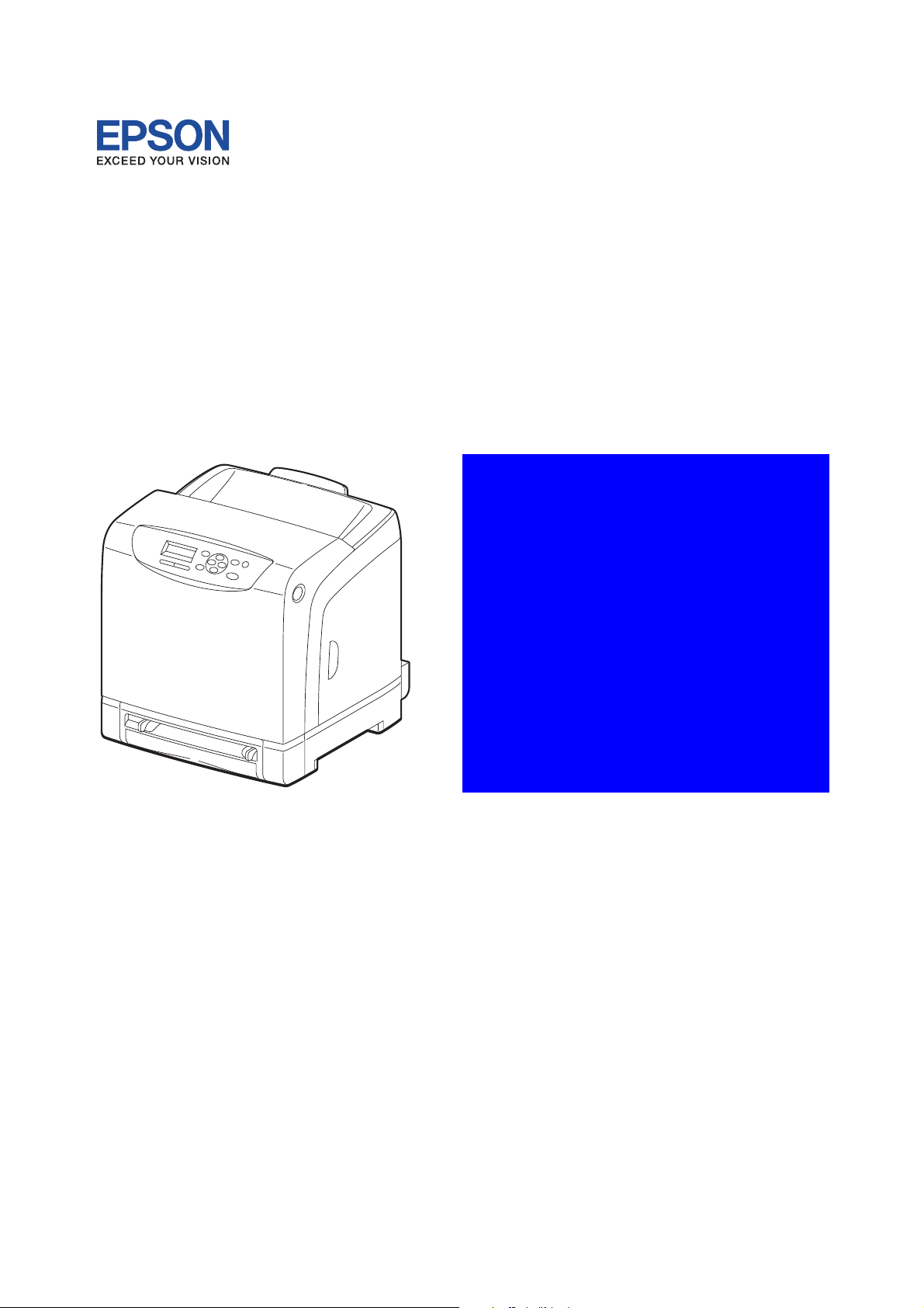
Laser Printer
Epson AcuLaser C2900N
SEPG11001
SERVICE MANUAL
Revision B
MiS00001SA
Epson AcuLaser C2900N
Confidential
Page 2

Revision B
Cautions
Operation contents of this document may be subject to modification without notice.
SEIKO EPSON will not assume responsibility for accidental or incidental damages resulting from
technical or editorial errors or omissions in this manual, the issue of this manual, the execution of
descriptions in this manual, or the use of this manual.
This document is protected by copyright. Do not photocopy or duplicate any part of this document in
any form without written permission from SEIKO EPSON.
Epson AcuLaser C2900N Confidential
i
Page 3
1. About this manual
This manual is a standard service manual of SEIKO EPSON containing information required for
maintenance of this laser printer (standard specifications).
2. Marks giving caution
Maintenance operations requiring special cautions or additional information regarding descriptions in
this manual are presented as "Warning," "Caution," or "Note," depending on their nature.
If instructions are not observed, death or serious injury may result.
If instructions are not observed, injuries to workers or physical damage to assets
(including this laser printer) may result.
Essentials for procedures, steps, rules, and others.
Revision B
Reference Incidental information to descriptions.
3. Related documents
- Instruction manuals (standard manuals)
Describe the operation and handling of this laser printer.
- Performance specifications
Describe in detail various specifications of this laser printer.
(In the event of a discrepancy between this ma nu al an d the performance specifications, the
performance specifications take pr ec ed e nc e.)
- Spare parts list
Information on maintenance parts (spare parts) for this laser printer.
Epson AcuLaser C2900N Confidential
ii
Page 4
4. Safety
To prevent possible accidents during maintenance operation, you should observe strictly the "Warning"
and "Caution" information in this manual.
Avoid dangerous operations and opera tio ns ou t of the sco p e of this ma nu al.
Various processes not covered by this manual may be required in actual operations, and should be
performed carefully, always giving attention to safety.
4.1 Power source
Keep the power plug disconnected during the maintenance operation to prevent electric shock, burns
and other damages.
If the power supply should be kept connected to measure voltage or for other similar reasons, take
sufficient care to prevent electric shock, by following the procedures in this manual.
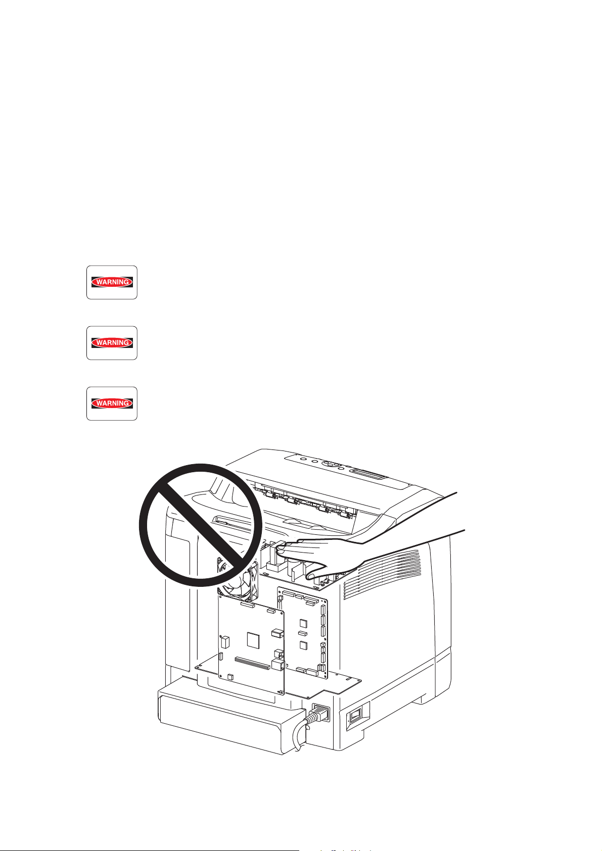
While the printer is on, never touch live parts if not required.
Power is supplied to the power switch / inlet even while the printer is off. Never
touch its live components.
Revision B
Do not touch live parts unless otherwise specified.
MiS00002SA
Epson AcuLaser C2900N Confidential
iii
Page 5

4.2 Driving units
When servicing gears or other driving units, be sure to turn off the power switch and unplug the power
cord. Drive them manually when required.
Do not do the print work removing the cover of the printer to confirm the operation
of driving part.
4.3 High-temperature units
When servicing high-temperature units (securing unit, etc.), be sure to turn them off to prevent burns,
injuries and other troubles. Remove the power plug and start service processes after they have cooled
down sufficiently.
Because high-temperature units are still hot after they complete an operation, wait
at least 40 minutes before starting maintenance service.
Revision B
Epson AcuLaser C2900N Confidential
iv
Page 6
4.4 Laser beams
• If your eyes are exposed to laser beams, you may lose your eyes ight.
• Never open the cover if the warning label for laser beams is attached there.
• Before disassembling and reassembling this laser printer, be sure to turn it OFF.
• When servicing this laser printer while it is running, be sure to follow the
procedures specified in this manual.
• You should be well aware that the laser beams are capable of injuring you and
other people near the printer.
Laser beams have features as follows:
• Frequencies are smaller in width than other beams (sun and electric bulbs) and
phases are uniform so that high monochromatic and convergence performance
can be obtained and thin beams of light can reach places at a long distance.
• Being highly converged, the laser beams exert a heating action that may be
harmful to human body.
Reference: The laser beams of this laser printer are invisible rays.
Revision B
ROS ASSY
MiS00003SA
Epson AcuLaser C2900N Confidential
v
Page 7
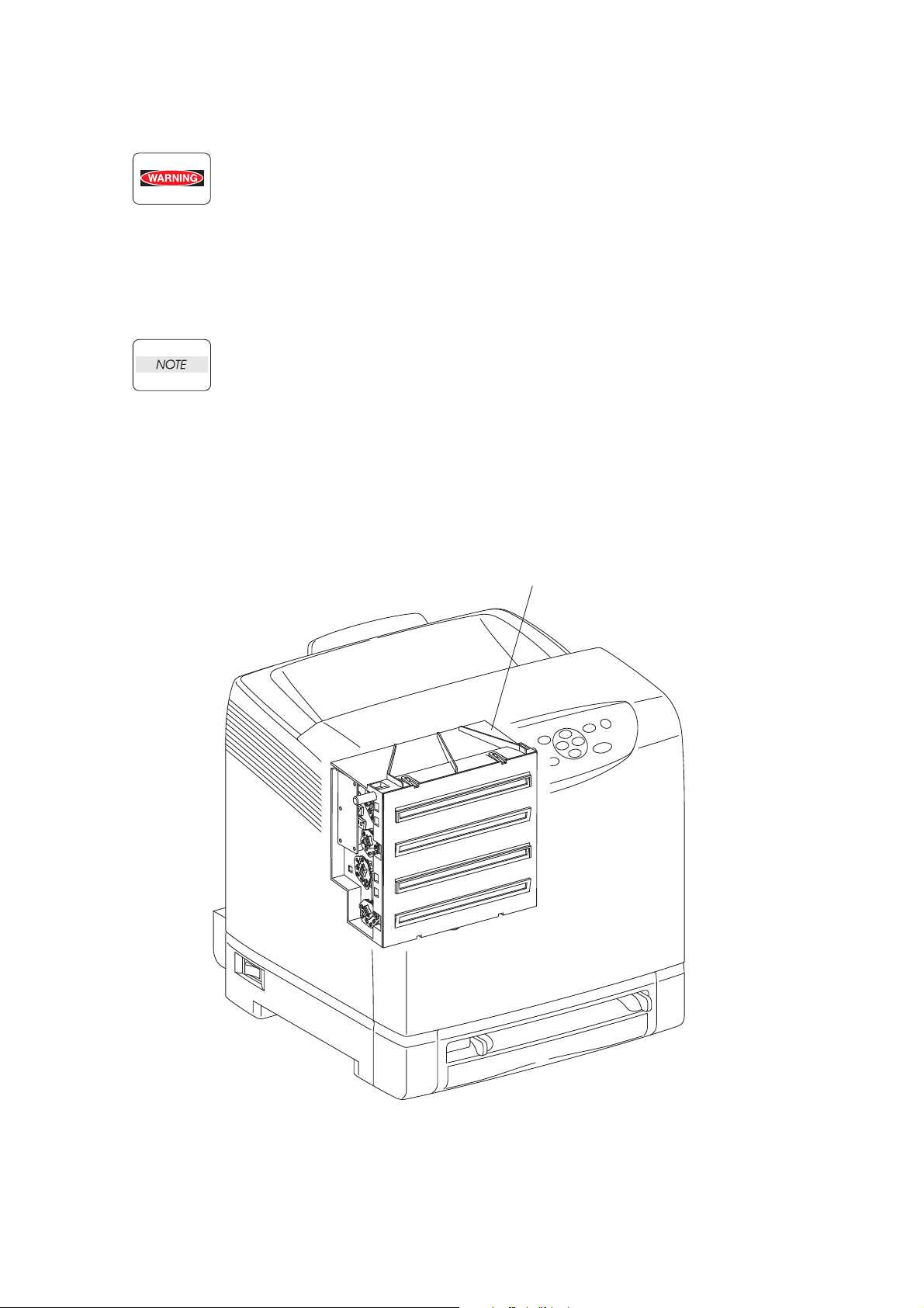
4.5 Warning/caution labels
MiS00004SA
Warning labels and caution labels are attached to this laser printer to prevent accidents Check those
labels for peeling or stains when servicing the printer.
4.5.1 Caution label for Printer
Revision B
Epson AcuLaser C2900N Confidential
vi
Page 8
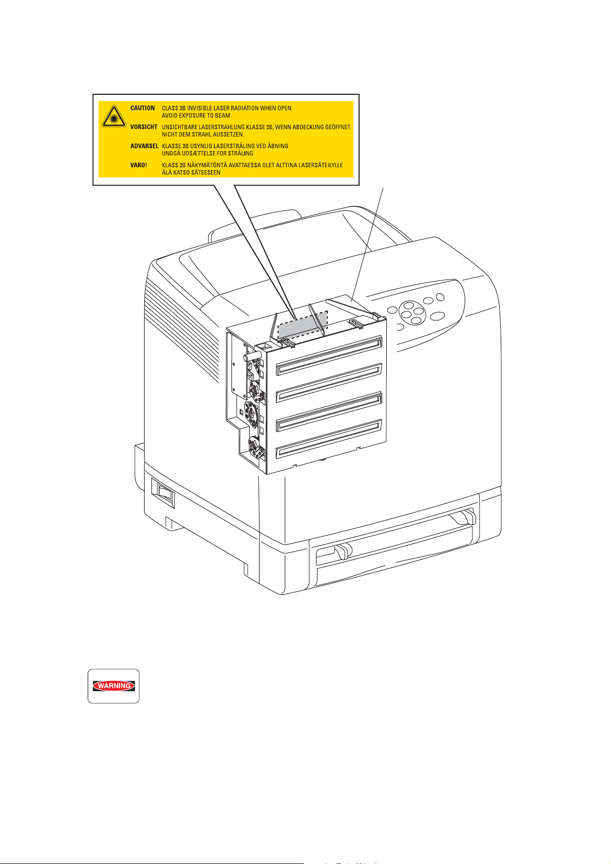
4.5.2 Caution label for ROS
MiS00005SA
ROS ASSY
Revision B
4.6 Others
• When air duster is used on the repair and the maintenance work, the use of the air
duster products containing the inflammable gas is prohibited.
• Make sure an antivirus software is installed on the computer used for service
support. Be sure to have the latest virus definition file for the software.
Epson AcuLaser C2900N Confidential
vii
Page 9
5. Unpacking the Printer
Take extreme care to avoid personal injuries.
Check the printer for evidence of any damages.
Peel all tapes off the printer.
Revision B
MiS00010GA
Epson AcuLaser C2900N Confidential
viii
Page 10
6. Revision History
MiS00007SA
Revision B
Revision Date of Issue Description
A May 20, 2011 First release
Revision up
Chapter3:
B July 7, 2011
RRP8.3 PWBA ESS SFP (PL8.1.5): revised the contents partially.
RRP8.9 PWBA MCU (PL8.2.13): revised the contents partially.
Epson AcuLaser C2900N Confidential
ix
Page 11

Revision B
CONTENTS
1. About this manual.............................................................................................................ii
2. Marks giving caution .........................................................................................................ii
3. Related documents........................................................................................................... ii
4. Safety ...............................................................................................................................iii
4.1 Power source.................................... ... .... ... ... ... .......................................... ... .... ... ... ... ...........................iii
4.2 Driving units......... ... ... .... ... ... ... .... ... .......................................... ... ... .... ... .................................................iv
4.3 High-temperature units .................................. ... ... .... ... ... ... .... ... ... ... .... ... ... ... ... ........................................iv
4.4 Laser beams..... ... ... ... .... ... .......................................... ... ... .......................................... . ...........................v
4.5 Warning/caution labels................ ... ... ... .... ... .......................................... ... ... ... .... ... ... ... .... .......................vi
4.5.1 Caution label for Printer.................................................................................................................vi
4.5.2 Caution label for ROS...................................................................................................................vii
5. Unpacking the Printer .....................................................................................................ix
6. Revision History...............................................................................................................ix
Chapter 1 Troubleshooting.............................................................................................1 - 1
Chapter 2 Operation of Diagnostic.................................................................................2 - 1
Chapter 3 Removal and Replacement Procedures........................................................3 - 1
Chapter 4 Plug/Jack(P/J) Connector Locations..............................................................4 - 1
Chapter 5 Parts List........................................................................................................5 - 1
Chapter 6 Principles of Operation ..................................................................................6 - 1
Chapter 7 Wiring Diagrams and Signal Information.......................................................7 - 1
Chapter 8 Product Specifications...................................................................................8 - 1
Epson AcuLaser C2900N Confidential
x
Page 12

Troubleshooting
CHAPTER
1
Confidential
Page 13

Chapter 1 Troubleshooting
Chapter 1 Troubleshooting CONTENTS
1. Troubleshooting Overview...........................................................................................1 - 1
1.1 Flow of Troubleshooting................. ... ... .... ... ... ... ... .... ... .......................................... ... ... .... ..................1 - 1
1.2 Check Installation Status .................................................................................................................1 - 2
1.3 Cautions on Service Operations .......................................................................................................1 - 3
1.4 Cautions on Using FIP...................................................................................................................... 1 - 4
1.5 Items To Be Confirmed Before Going To FIP Troubleshooting ........................................................1 - 6
2. FIP............................................................................................................................1 - 12
2.1 FIP ...................................... ... .... ... ... ... .... ... .......................................... ... ... ....................................1 - 12
2.2 Flow of FIP..................................................................................................................................... 1 - 12
2.3 Status Code List............................ ... ... .... ... ... ... ... .......................................... .... ... ... ... ....................1 - 13
3. Error Code FIP ..........................................................................................................1 - 25
4. Image Quality Trouble.............................................................................................1 - 126
4.1 Entry Chart for Image Quality Troubleshooting............................................................................. 1 - 126
4.2 Print Image Quality Specifications ........................................................... ... ... .... ... ........................1 - 130
4.3 Image Quality FIP...... .... ... ... ... .... ... ... ... .......................................... .... ... ... ... ... ...............................1 - 134
5. Abnormal Noise Trouble.......................................................................................... 1 - 173
5.1 Entry Chart for Abnormal Noise Troubleshooting .........................................................................1 - 173
5.2 Operation Mode Table............ .... ... .......................................... ... ... .... ... ... ... ... .... ... ... .....................1 - 174
6. Other FIP.................................................................................................................1 - 180
Epson AcuLaser C2900N Confidential
Page 14
Chapter 1 Troubleshooting
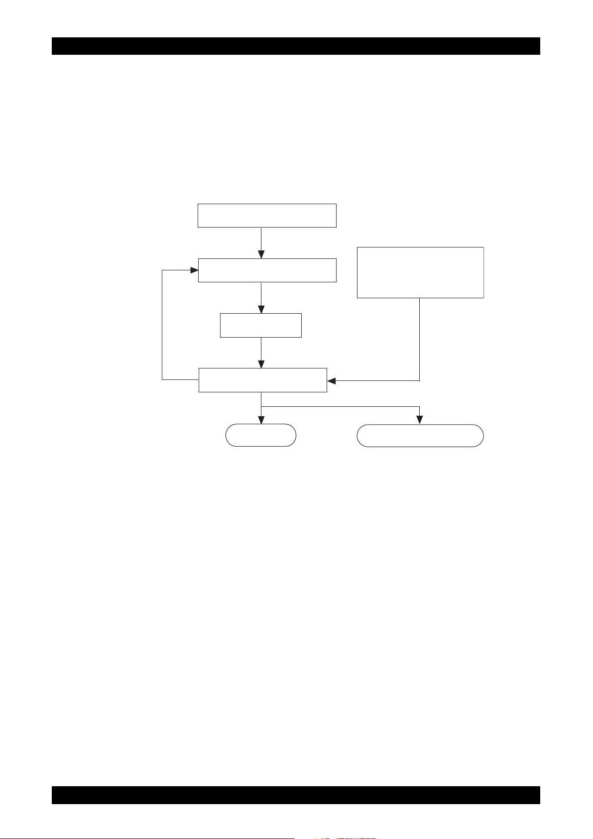
Check installation status
Check trouble status
Execute FIP
Check for recovery
End Replace the Printer.
Operation of Diagnostic
Principles of Operation
Wiring Diagrams
Reference
information
If the problem persists
1. Troubleshooting Overview
To increase the efficiency of troubleshooting, ensure that preliminary checks should be made to confirm
the trouble status before proceeding to the Fault Isolation Procedure (FIP), Operation of Diagnostic
(Chapter 2), Wiring Diagrams (Chapter 7), and Principles of Operation (Chapter 6).
1.1 Flow of Troubleshooting
Flow of the troubleshooting is as follows:
Revision B
Epson AcuLaser C2900N
1 - 1
Confidential
Page 15

Chapter 1 Troubleshooting
1.2 Check Installation Status
Be sure to check the following items before starting the troubleshooting procedures
1) The power supply voltage is within the specifications (measure the voltage at the wall outlet).
2) Power cord is free from breakage, short-circuit, disconnected wire, or incorrect connection in the
power cord.
3) The printer is properly grounded.
4) The printer is not installed at a place subjected to high/low temperature, hum idity, and sudden te mperature changes.
5) The printer is not installed at or near water facilities, humidifier, heating appliance, fire, dust, or in
airflow from air conditioner.
6) The printer is not installed in a place subjected to volatile or inflammable gas.
Revision B
7) The printer is not installed under direct sunlight.
8) The printer is installed in a well-ventilated place.
9) The printer is installed on a firm and stable surface.
10) The paper meets the specifications (standard paper is recommended).
11) The printer is handled properly.
12) The high frequency service items are replaced at the recommended print count intervals.
Epson AcuLaser C2900N
1 - 2
Confidential
Page 16
Chapter 1 Troubleshooting
1.3 Cautions on Service Operations
1) Be sure to remove the power cord unless otherwise required.
While the printer is powered ON, never touch the conductive parts unless
otherwise required.
Never touch the conductive parts of the power switch and inlet of the LVPS,
because they are live even while the printer is powered off.
2) When checking some parts with covers removed and with the interlock, safety, and power switches
ON, disconnect the connectors (P/J411 and P/J412) on the ROS ASSY except unless otherwise
required.
When checking some parts with covers removed and with the interlock, safety, and
power switches ON, laser beams may be irradiated from the ROS ASSY. For your
safety, be sure to disconnect the connec tors (P/J411 and P/J 412 ) unless otherwise
required.
3) When checking some parts with the Front Cover removed and the printer powered ON, be sure to
remove the connector (P/J16) on the PWBA MCU unless otherwise required.
When checking some parts with the Front Cover removed and the printer powered
ON, be sure to remove the connector (P/J16 ) on the MCU. Otherwise, a high voltage
may be output from the HVPS.
When connecting the connector (P/J16) on the MCU according to the instructions
in the FIP, never touch the HVPS and high voltage parts.
Revision B
4) When outputting a high voltage using the Diag Tool, etc., keep all the covers on unless otherwise
required.
When outputting a high voltage using the Diag Tool, etc., ensure that:
- The high voltage carrying parts must never be touched.
- The instructions in this manual must be followed.
5) When operating the drive unit using the Diag Tool, etc., keep all the covers on unless otherwise
required.
When operating the drive unit using the Diag Tool, etc., ensure that:
- The drive unit must never be touched.
- The instructions in this manual must be followed.
6) When touching hot parts, be careful not to get burnt.
7) While working, be sure to wear a wrist band or the like to dissipate static charges from your body.
Epson AcuLaser C2900N
1 - 3
Confidential
Page 17

Chapter 1 Troubleshooting
1.4 Cautions on Using FIP
1) When troubleshooting according to the FIP, have on hand a normal MCU, LVPS, HVPS, Fuser
Unit, TRANSFER ASSY, etc., for possible fault isolation.
2) In the initial check according to the FIP, check only items which can be simply checked.
3) In the initial check according to the FIP, check the constitutive parts of the major check parts and
related parts, as well as major check parts.
4) When working with the printer, be sure to remove the power cord unless otherwise required. Never
touch live parts if not required, while the power cord is connected.
5) Connector condition is denoted as follows:
[P/J12]
[P12]
[J12]
Connector (P/J12) is connected.
Plug side with the connector (P/J12) removed (except when attached directly to the
board).
Jack side with the connector (P/J12) removed (except when attached directly to the
board).
Revision B
6) [P/J1-2PIN <=> P/J3-4PIN] in the FIP means measurement with the positive side of the measuri ng
instrument connected to [2PIN] of [P/J1] and the negative side to [4PIN] of [P/J3].
7) [P/J1<=> P/J2] in the FIP means measurement for all terminals corr espondin g between [P/J1] and
[P/J2] based on “Wiring Diagrams”.
8) In [P/J1-2PIN <=> P/J3-4PIN] in the FIP where voltage is measured, [P/J3-4PIN] on the rear
negative side is always at the AG (analog ground), SG (signal ground), or RTN (return).
Therefore, after checking of proper conductivity between AGs, SGs, or RTNs respectively, the rear
negative side can be connected to the PIN of AG, SG or RTN instead of [P/J3-4PIN].
However, care should be taken not to confuse [AG], [SG], and [RTN] because they are not on the
same level.
9) When measuring the voltage at small connectors, use the dedicate d tool. Handle the tool with ca re
because its business end is pointed.
10) When measuring the voltage, set the TRANSFER ASSY, toner cartridge and sheet feeder, close
the COVERs and power ON unless otherwise required .
11) Numerical values in the FIP are only for guideline. Approximate values are acceptable.
12) In each step of the FIP, parts removal and other procedures implicitly required for the ste p are
omitted.
13) In the FIP, "Replacement" means the replacement of the parts that are consider ed to be the cause
of the trouble. Replacement of those parts means the replacement of the assembly part (HIGH
ASSY) that contain them.
Epson AcuLaser C2900N
1 - 4
Confidential
Page 18

Chapter 1 Troubleshooting
14) In the FIP, the sheet feeder immediately below the printer main body is called "Tray 1", and the
cassette below it is called "Tray 2".
15) Some of the instructions in the FIP are branched off depending on the specifications. Follow the
applicable instruction.
16) For some optional components, you may have to refer to the manual of the relevant compo nent for
troubleshooting. Have the relevant manual at hand as needed.
Revision B
Epson AcuLaser C2900N
1 - 5
Confidential
Page 19

Chapter 1 Troubleshooting
1.5 Items To Be Confirmed Before Going To FIP Troubleshooting
Basic Printer Problems
Some printer problems can be easy to resolve. If a problem occurs with your printer, check each the following:
1) If a message is displayed on the LCD of operator panel, see “2.3 Status Code List”.
2) The printer power cable is plugged into the printer and a properly grounded electrical outlet.
3) The printer power is powered ON.
4) The electrical outlet is not turned off by any switch or breaker.
5) Other electrical equipment plugged into the outlet is working.
6) All options are properly installed.
7) If you have checked all of the above and still have a problem, turn off the printer, wait for 10 sec-
onds, and then turn on the printer. This often solves the problem.
8) If the printer does not start-up after downloading the ESS firmware, or does not operate normally,
execute the download of ESS firmware again by the download mode (Refer to “1.2 Firmware
version up procedure using the download mode” of Appendix_1.).
Display Problems
1) If the operator panel displays only diamonds or is blank, check and try the action below.
If the problem persists even after checking and executing the items below, execute "FIP- AC
Power" or "FIP DC Power".
a) Turn off the printer, wait for 10 seconds, and turn on the printer.
b) Self Test Message appears on the operator panel. When the test is completed, “Ready to
Print” is displayed.
2) If menu settings changed from the operator panel have no effect, check and try the actions
below.
Settings in the software program, the printer driver, or the printer utilities are overriding the settings made on the operator panel.
a) Change the menu settings from the printer driver, the printer utilities, or the software pro-
gram instead of the operator panel.
b) Disable the settings in the printer driver, the printer utilities, or the software program so you
can change settings on the operator panel.
Revision B
Printing Problems
1) If a job did not print correct or incorrect characters were printed, check and try the actions below.
a) Make sure “Ready to Print” appears on the operator panel before sending a job to print.
Press Menu to return to “Ready to Print”.
b) Make sure print media is loaded in the printer. Press Menu to return to “Ready to Print”.
c) Verify that you are using the correct printer driver.
d) Make sure you are using the correct Ethernet or USB cables and it securely connected at
the back of the printer.
e) Verify that the correct print media size is selected.
f) If using a print spooler, verify that the spooler has not stalled.
g) Check the printer interface from the “Configure” menu. Determine the host interface you are
using. Print a Panel Setting page to verify that the current interfaces settings are correct.
h) Output fonts will not print correctly using the PCL driver in its default mode. To correct this
problem, use PostScript driver when using the PCL driver.
Epson AcuLaser C2900N
1 - 6
Confidential
Page 20

Chapter 1 Troubleshooting
2) If secure print is not available or not printing, refer to the requirements below.
a) Minimum 256 MB is required.
b) RAM Disk must be enabled using the operation panel.
c) The number of secure print jobs your printer can store is dependent on the job size includ-
ing number of pages, graphics, color attributes, and the amount of memory installed. To
increase this number, add additional memory.
3) If print media misfeeds or multiple feeds occur, check and try the actions below.
a) Make sure the print media you are using meets the specifications for your printer. Refer to
Print Media Guidelines of this section.
b) Flex print media before loading it in any of the sources.
c) Make sure the print media is loaded correctly.
d) Make sure the width and length guides on the print media sources are adjusted correctly.
e) If the print media are overfilled in sources, reduce the amount of media.
f) Load the recommended print side correctly for the type of print media you are using.
g) Turn the print media over or around and try printing again to see if feeding improves.
h) Check the print media type loaded in the source, and refill only one type of print media, if
print media types are mixed.
i) Refill a new ream of print media, if some reams are mixed.
j) Remove the top and bottom sheets of a ream before loading the print media.
k) Do not reload print media until the print media source is empty.
4) If envelope misfeeds or multiple feeds occur, check and try the action below.
a) Remove the stack of envelops from the Single Sheet Inserter (SSI).
5) If page breaks in unexpected places, check and try the action below.
a) Check the “Job Time-out” in the Basic Settings menu and increase the value.
6) If a job prints from the wrong source or on the wrong print media, check and try the action below.
a) Check the “Paper Size” and “Paper Type” in the Tray Se ttings menu on the printer op erator
panel and in the printer driver.
7) If print media does not stack neatly in the output tray, check and try the action below.
a) Turn the print media stack over in the tray or multipurpose feeder.
Revision B
Print Media Guidelines
Print media refers to paper, labels, envelopes, and coated paper among others. Your printer provides
high-quality printing on a variety of print media. Selecting the appropriate print media for your printer
helps avoid printing troubles. This section describes selecting print media, caring for print media, and
loading the print media in the standard 250-sheet tray.
Paper
For the best print quality in color, use 75 g/m
quality in black and white, use 90 g/m
2
you perform trial print before purchasing large quantities of print media.
When loading paper, identify the recommended print side on the paper package, and load the paper
accordingly. See "Loading Print Media in the Standard 250-Sheet Tray and the Optional 2 50-Sheet
Feeder" and "Loading Print Media in the SSI" for detailed loading instructions.
Paper Characteristics
The following paper characteristics affect print quality and reliability. It is recommended that you follow
these guidelines when evaluating new paper stock.
Epson AcuLaser C2900N
2
(20 lb) xerographic, grain long paper. For the best print
(24 lb) xerographic, grain long paper. It is recommended that
1 - 7
Confidential
Page 21

Chapter 1 Troubleshooting
Weight
The tray automatically feeds paper weights from 60 g/m
The single sheet feeder automatically feeds paper weights from 60 g/m
2
bond) grain long. Paper lighter than 60 g/m
For best performance, use 75 g/m
2
(20 lb bond) grain long paper.
(16 lb) may not feed properly, and could cause paper jams.
2
to 216 g/m2 (16 lb to 80 lb bond) grain long.
2
to 216 g/m2 (16 lb to 80 lb
Curl
Curl is the tendency of print media to curve at its edges. Excessive curl can cause pape r feeding problems. Curl usually occurs after the paper passes through the printer, where it is exposed to high temperatures. Storing paper unwrapped, even in the paper tray, can contribute to paper curling prior to
printing and cause feeding problems regardless of humidity. When printing on curled paper, straighten
the paper and then insert it into the single sheet feeder.
Smoothness
The degree of paper smoothness directly affects the print quality. If the paper is too rough, the toner
does not fuse on to the paper properly, resulting in poor print quality. If the paper is too smooth, it can
cause paper feeding problems. Smoothness between 150 and 250 Sheffield points produces the best
print quality.
Moisture Content
The amount of moisture in the paper affects both the print quality and the ability of the printer to feed
the paper properly. Leave the paper in its original packaging until you are ready to use it. T his limits the
exposure of the paper to moisture changes that can degrade its performance.
Grain Direction
Grain refers to the alignment of the paper fibers in a sheet of paper. Grain is either grain long, running
the length of the paper, or grain short, running the width of the paper. For 60 g/m
36 lb bond) paper, grain long fibers are recommended. For paper heavier than 135 g/m
2
to 135 g/m2 (16 lb to
2
(36 lb bond),
grain short is preferred.
Fiber Content
Most high-quality xerographic paper is made from 100% chemically pulped wood. Paper containing
fibers such as cotton may lead to degraded paper handling.
Revision B
Recommended Paper
To ensure the best print quality and feed reliability, use 75 g/m
2
(20 lb) xerographic paper. Business
paper designed for general business use also provides acceptable pri nt quality. Only use paper able to
withstand high temperatures without discoloring, bleeding, or releasing hazardous emissions. The laser
printing process heats paper to high temperatures. Check with the manufacturer or vendor to dete rmine
whether the paper you have chosen is acceptable for laser printers.
It is recommended that you perform trial print before purchasing large quantities of print media. When
choosing any print media, you should consider the weight, fiber content, and color.
Unacceptable Paper
The following paper types are not recommended for use with the printer :
• Chemically treated paper used to make copies without carbon paper, also known as carbonless
paper, carbonless copy paper (CCP), or no carbon required (NCR) paper.
• Preprinted paper with chemicals that may contaminate the printer.
• Preprinted paper that can be affected by the temperature in the fuser unit.
• Preprinted paper that requires a registration (the precise print location on the page) greater than
±0.09 inches, such as optical character recognition (O CR) form s.
Epson AcuLaser C2900N
1 - 8
Confidential
Page 22

Chapter 1 Troubleshooting
In some cases, you can adjust registration with your software program to successfully print on these
forms.
• Coated paper (erasable bond), synthetic paper, and thermal paper.
• Rough-edged, rough or heavily textured surface paper, or curled paper.
• Recycled paper containing more than 25% post-consumer waste that does not meet DIN 19 309.
• Multiple-part forms or documents.
• Print quality may deteriorate (blank spaces or blotches may appear in the text) when printing on talc
or acid paper.
Selecting Paper
Proper paper selection helps prevent jams an d en su re s tro u ble-free printing.
To help avoid jams or poor print quality:
• Always use new, undam a ge d pa p er .
• Before loading the paper, identify the recommended print side of the paper.
This information is usually indicated on the paper package.
• Do not use paper that you have cut or trimmed.
• Do not mix print media sizes, weights, or types in the same source. This may result in a paper jam.
• Do not remove the tray while printing is in progress.
• Ensure that the paper is properly loaded in the tray.
• Flex the paper back and forth, and then fan them. Straighten the edges of the stack on a level sur-
face.
Revision B
Epson AcuLaser C2900N
1 - 9
Confidential
Page 23
Chapter 1 Troubleshooting
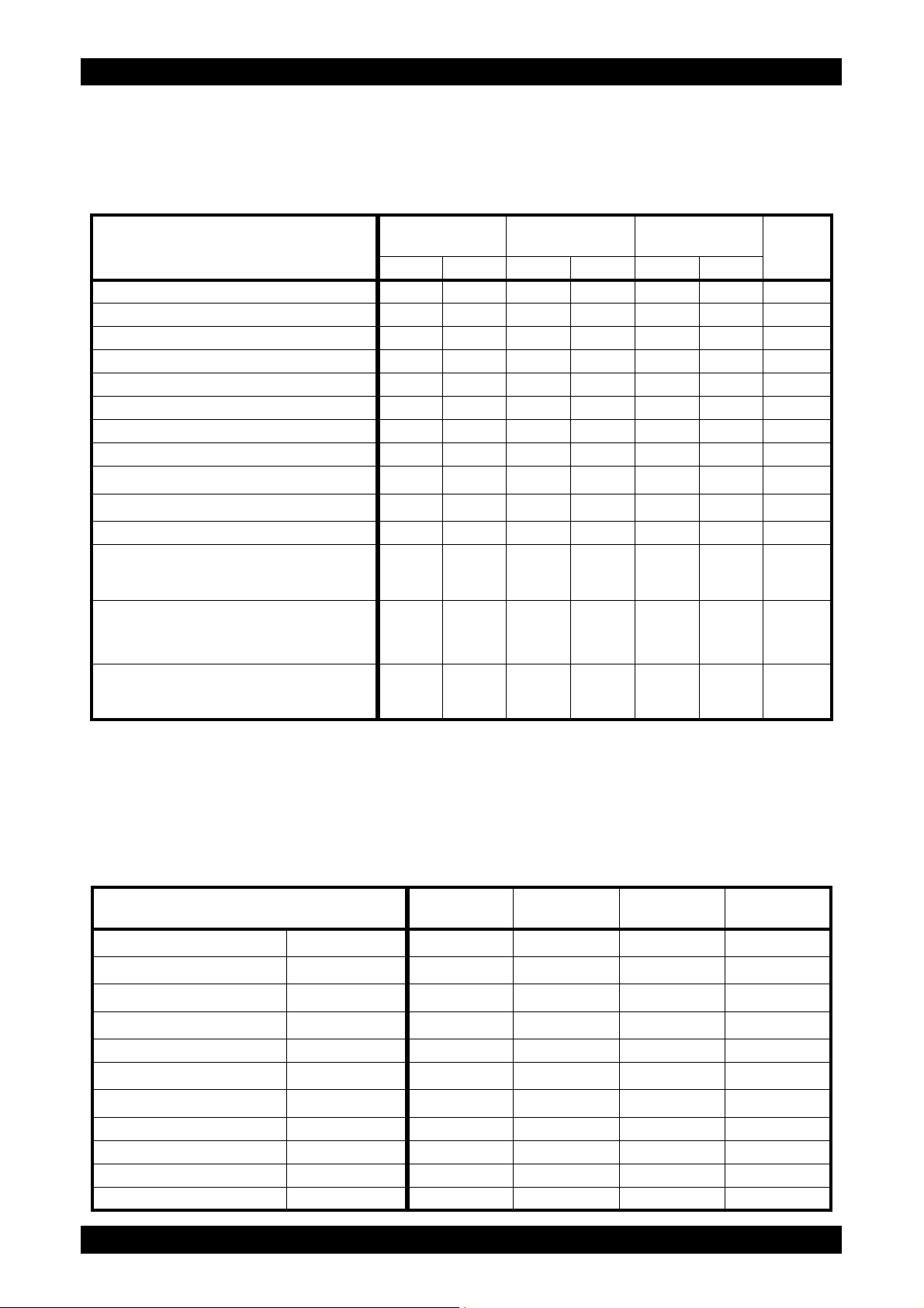
Identifying Print Media Sources and Specifications
The following tables provide information on stan d ar d an d op tio nal print me d i a so ur ces.
Supported Paper Sizes
Revision B
Paper size
Single Sheet
Inserter
Standard 250-
sheet tray
Optional 250-
sheet feeder
Duplexer
Side 1 Side 2 Side 1 Side 2 Side 1 Side 2
A4 (210 x 297 mm) YYYYYYY
B5 (182 x 257 mm) YYYYYYN
A5 (148 x 210 mm) YYYYYYN
Letter (8.5 x 11 inches) YYYYYYY
Folio (8.5 x 13 inches) YYYYYYY
Legal (8.5 x 14 inches) YYYYYYY
Executive (7.25 x 10.5 inches) YYYYYYN
Envelope #10 (4.125 x 9.5 inches) Y N Y N N N N
Monarch (3.875 x 7.5 inches)
DL (110 x 220 mm)
*3
Y
*3
Y
NYNNNN
NYNNNN
C5 (162 x 229 mm) Y N Y N N N N
Custom
Width: 76.2 to 215.9 mm (3 to 8.5 inches)
Length: 127 to 355.6 mm (5 to 14 inches)
Custom
Width: 76.2 to 215.9 mm (3 to 8.5 inches)
Length: 127 to 355.6 mm (5 to 14 inches)
Custom
Width: 148.0 to 215.9 mm (5.8 to 8.5 inches)
Length: 210.0 to 355.6 mm (8.3 to 14 inches)
*1
*2
YYNNNNN
NNYYNNN
NNNNYYN
*1: Maximum width 220 mm for envelope (DL LEF)
DL and Monarch can be supported by LEF with flap opened.
*2: Minimum length 98.4 mm for envelope (Monarch LEF)
*3: Monarch LEF and DL LEF are not available.
Supported Paper Types
Single Sheet
Inserter
2
2
2
2
YYYY
YYYY
YYYY
YYYY
Plain
Letterhead
Hole Punched
Colored
Paper type
60 to 90 g/m
60 to 105 g/m
60 to 105 g/m
60 to 105 g/m
Special --- Y Y N N
Lightweight Cardstock
Heavyweight Cardstock
106 to 163 g/m
164 to 216 g/m
2
2
YYNN
YYNN
Lightweight Glossy Card --- Y N N N
Heavyweight Glossy Card --- Y N N N
Labels --- Y Y N N
Envelopes --- Y Y N N
Epson AcuLaser C2900N
1 - 10
Standard 250-
sheet tray
Optional 250-
sheet feeder
Duplexer
Confidential
Page 24

Chapter 1 Troubleshooting
Paper Type Specifications
Paper type Weight Remarks
Plain
Plain Thick
Recycled
60 to 90 g/m
80/90 to 105 g/m
60 to 105 g/m
2
2
2
Labels --- Inkjet printer paper cannot be used.
Covers
Covers Thick
106 to 163 g/m
164 to 216 g/m
2
2
Envelope --- --Coated
Coated Thick
106 to 163 g/m
164 to 216 g/m
2
2
Letterhead --- --Preprinted
Prepunched
Colored
64 g/m
64 g/m
64 g/m
2
2
2
---
---
---
---
---
Inkjet printer paper cannot be used.
Inkjet printer paper cannot be used.
---
---
---
Revision B
Epson AcuLaser C2900N
1 - 11
Confidential
Page 25
Chapter 1 Troubleshooting
N
Y
Y
N
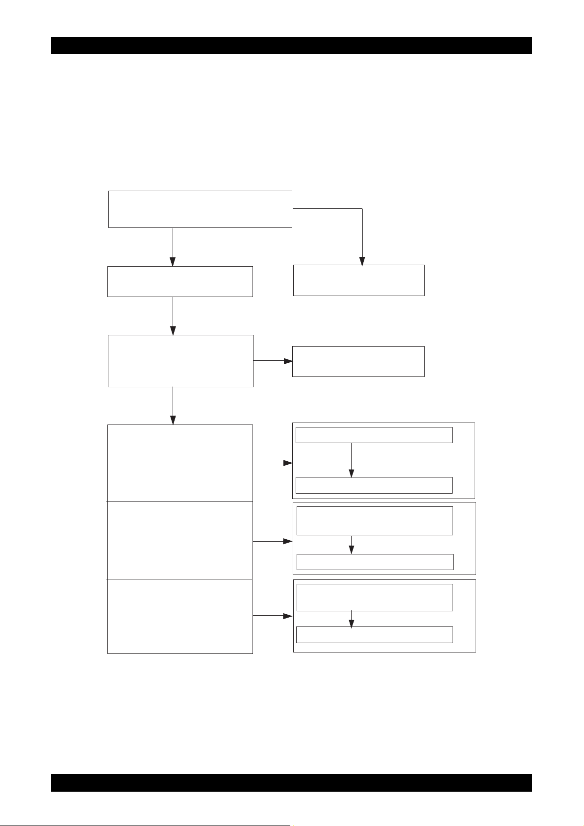
Ask the operator about trouble status.
Is operator’s operating method correct?
Turn off and turn on the Power.
Does error still occur when print
is done by the problem mode?
When status code or LCD
display is displayed:
When image quality trouble
is occurred:
When abnormal noise
is occurred:
Instruct how to operate
End of work
Refer to "2.3 Status Code List."
Refer to "3 Error Code FIP."
Refer to "4.1 Entry Chart for Image
Quality Troubleshooting."
Refer to "4.3 Image Quality FIP."
Refer to "5.1 Entry Chart for
Abnormal Noise Troubleshooting."
Refer to "5.2 Operation Mode Table."
2. FIP
2.1 FIP
The FIP is the first step for trouble diagnosis. The FIP isolates the presence of various troubles
including error codes, and guides the troubleshooting procedure.
2.2 Flow of FIP
Revision B
Epson AcuLaser C2900N
1 - 12
Confidential
Page 26
Chapter 1 Troubleshooting
Flip
Flip
Flip
Flip
Flip
Flip
Flip
Flip
Flip
2.3 Status Code List
Errors that occur when optional components are installed are gray-shaded.
Revision B
Status
Code
004 310
317
351
010
397
421
500
501
016
502
520
Error Message
LCD
Reseat Feeder
Restart Printer
Error 004-310
Restart Printer
Insert Fuser
010-317
Insert Fuser
Restart Printer
Replace Fuser
010-351
Replace Fuser
Restart Printer
Fuser Error
Restart Printer
Error 010-397
Restart Printer
Ready to Print
Fuser Life
Ready to Print
Replace Soon
Erase Flash Err
Restart Printer
Error 016-500
Restart Printer
Write Flash Err
Restart Printer
Error 016-501
Restart Printer
Verify Flash Err
Restart Printer
Error 016-502
Restart Printer
Certificate Fail
Contact Admin.
Error 016-520
Restart Printer
Status Contents
<IOT Option Feeder I/F Failure>
The Option Feeder communication failure is detected.
<IOT Fuser Unit Detached>
Fuser unit detached is detected.
<IOT Fuser Unit Life Over>
The value of fuser unit counter has reached the replacement
time.
<IOT Fuser Unit Failure>
The operation error of fuser unit (Temperature anomaly error
etc.) is detected.
<IOT Fuser Unit Near Life>
The fuser unit is approaching the replacement time.
<Download Delete Error>
Flash memory erase error occurred.
<Download Write Error>
Flash memory write error occurred.
<Download V erify Error>
Flash memory verify error occurre d .
<Ipsec Certificate Error>
Ipsec Certificate Error.
FIP to be
referred
FIP-1.1
FIP-1.2
FIP-1.3
FIP-1.4
FIP-1.5
FIP-1.6
FIP-1.6
FIP-1.6
FIP-1.7
Epson AcuLaser C2900N
1 - 13
Confidential
Page 27
Chapter 1 Troubleshooting
Flip
Flip
Flip
Flip
Flip
Flip
Flip
Flip
Flip
Flip
Revision B
Status
Code
016
Error Message
Out of Memory
Press Ok Button
718
Error 016-718
Press Ok Button
PDL Error
Press Ok Button
720
Error 016-720
Press Ok Button
Format Error
Press Ok Button
737
Error 016-737
Press Ok Button
Protection Error
Press Ok Button
741
Error 016-741
Press Ok Button
Invalid ID
Press Ok Button
742
Error 016-742
Press Ok Button
Range Chk Error
Press Ok Button
743
Error 016-743
Press Ok Button
Check Sum Error
Press Ok Button
744
Error 016-744
Press Ok Button
Header Error
Press Ok Button
745
Error 016-745
Press Ok Button
Wrong Password
Press Ok Button
753
Error 016-753
Press Ok Button
PDF Print
Disabled
755
Error 016-755
Press Ok Button
LCD
Status Contents
<Memory Over flow>
The current printing job process cannot be continued because
the memory capacity is exceeded.
<PDL Error>
The print data cannot be processed by PDL.
<Download Format Error>
Download file format is invalid.
<Download Protect Error>
Performed FW download although FW update is prohibited by
panel settings.
<Download ID Error>
Download file ID is invalid.
<Download Range Error>
At download, write-in destination address is invalid. Range
check error.
<Download Check Sum Error>
Download file checksum is invalid.
<Download header Error>
Download file header is invalid.
<PDF password error>
PDF password error.
<PDF print disabled error>
PDF print is not allowed.
FIP to be
referred
FIP-1.8
FIP-1.9
FIP-1.10
FIP-1.10
FIP-1.10
FIP-1.10
FIP-1.10
FIP-1.10
FIP-1.11
FIP-1.11
Epson AcuLaser C2900N
1 - 14
Confidential
Page 28
Chapter 1 Troubleshooting
Flip
Flip
Flip
Flip
Flip
Flip
Flip
Flip
Flip
Revision B
Status
Code
016
024
Error Message
Invalid User
Press Ok Button
757
Error 016-757
Press Ok Button
Disabled Func
Press Ok Button
758
Error 016-758
Press Ok Button
Limit Exceeded
Press Ok Button
759
Error 016-759
Press Ok Button
Invalid Job
Press Ok Button
799
Error 016-799
Press Ok Button
Disk Full
Press Ok Button
982
Error 016-982
Press Ok Button
MCU Firmware Err
Restart Printer
340
Error 024-340
Restart Printer
Download Mode
Send FW Data
360
Error 024-360
Send FW Data
PAGEC Time Error
Restart Printer
362
Error 024-362
Restart Printer
MCU Comm. Error
Restart Printer
371
Error 024-371
Restart Printer
Press Ok Button
985
to continue
LCD
<Auditron - Invalid User>
An error occurred because the user's account settings did not
match those of the Administrator.
<Auditron - Disabled Function>
An error occurred because a user authorized only for B&W
print attempted to execute color printing.
<Auditron - Reached Limit>
An attempt was made to print more copies than the print count
limit.
<Job Environment Violation>
Detects violation data for the print condition. The print data
specifies paper type/ size not available for the printer.
This code is given when the Optional Memory Module is installed.
<Disk Full>
The current printing job process cannot be continued because
the RAM disk is full.
<IOT Firmware Error>
MCU firmware error occurs.
<MCU DownLoad Error>
Download failure of MCU firmware.
<IOT Start Image Marking Timeout>
"Start Image Making" has not been issued within the time
allowed.
<MCU-ESS Communication Fail>
Communication fail between MCU and ESS.
<Waiting for "Continue" key to be pressed afte r reloading
paper to the SSI>
Printer starts printing automatically after a certain period of
time even if the key is not pressed.
Status Contents
FIP to be
referred
FIP-1.12
FIP-1.13
FIP-1.14
FIP-1.15
FIP-1.16
FIP-1.17
FIP-1.18
FIP-1.19
FIP-1.20
FIP-1.21
Epson AcuLaser C2900N
1 - 15
Confidential
Page 29
Chapter 1 Troubleshooting
Flip
Flip
Flip
Flip
Flip
Flip
Flip
Flip
Flip
Flip
Revision B
Status
Code
446
027
452
041 340
313
325
326
042
372
373
700
061 370
Error Message
LCD
Ready to Print
IPv6 Duplicate
Change IPaddress
Ready to Print
IPv4 Duplicate
Change IPaddress
MCU NVRAM Error
Restart Printer
Error 041-340
Restart Printer
Fan Motor Error
Restart Printer
Error 042-313
Restart Printer
Motor Error
Restart Printer
Error 042-325
Restart Printer
Motor Error
Restart Printer
Error 042-326
Restart Printer
K Mode Sol Error
Restart Printer
Error 042-372
Restart Printer
K Mode Sol Error
Restart Printer
Error 042-373
Restart Printer
Over Heat
Please Wait...
Error 042-700
Please Wait...
Laser Error
Restart Printer
Error 061-370
Restart Printer
Status Contents
<IPv6 duplicate>
Duplicate IPv6 addresses detected upon startup.
<IPv4 duplicate>
Duplicate IPv4 addresses detected upon startup.
<IOT NVRAM Error>
The operation error of NVM (read/write check error etc.) is
detected.
<IOT Fan Motor Failure>
MCU detects an error upon receiving error signal from the
Fan.
<IOT Main Motor Failure>
Main Motor failure is detected.
<IOT Sub Motor Failure>
Sub Motor failure is detected.
<IOT K Mode Solenoid Error 1>
The error is generated when K Mode Solenoid (Color Mode
Switching Solenoid) does not operate in specified time.
<IOT K Mode Solenoid Error 2>
The error is generated when the gear which ope rates by K
Mode Solenoid (Color Mode Switching Solenoid) rotates two
times.
<IOT Over Heat Stop>
The temp. Sensor sensed high temperature.
<IOT ROS Failure>
The operation error of ROS (rotational error etc.) is detected.
FIP to be
referred
FIP-1.22
FIP-1.22
FIP-1.23
FIP-1.24
FIP-1.25
FIP-1.26
FIP-1.27
FIP-1.27
FIP-1.28
FIP-1.29
Epson AcuLaser C2900N
1 - 16
Confidential
Page 30

Chapter 1 Troubleshooting
Flip
Flip
Flip
Flip
Flip
Flip
Flip
Flip
Flip
Flip
Revision B
Status
Code
071 100
100
101
072
215
216
900
101
075
102
923
100
077
101
Error Message
LCD
Jam at Tray 1
Check Tray 1
Open Front Cover
This code is given when the Option 250 Sheet Feeder is installed.
Jam at Tray 2
Check Tray 2
Open Front Cover
Jam at Tray 2
Open Tray 2
Open Front Cover
This code is given when the Optional 250-Sheet Feeder is installed.
250 Feeder Error
Restart Printer
Error 072-215
Restart Printer
Motor Error
Restart Printer
Error 072-216
Restart Printer
Jam at
Tray 1 or 2
Open Tray 1 or 2
Open Front Cover
Jam at Front
Cover
Open Front Cover
and Remove Paper
Chk Manual Feed
Remove Paper
Open and close
Front Cover
Reseat paper
of Manual Feed
Jam at Front
Cover
Open Front Cover
and Remove Paper
Jam at Front
Cover
Open Front Cover
and Remove Paper
Status Contents
<IOT Tray1 Misfeed JAM>
The Regi Sensor is not turned ON within the specified time
after feeding a paper from Tray 1.
<IOT Tray2 Misfeed JAM>
The Paper Path Sensor of Tray 2 is not turned ON within the
specified time after feeding a paper from Tray 2.
<IOT Feeder 2 JAM>
A jam has been detected between the Regi Sensor and the
Paper Sensor of Tray 2.
<IOT Feeder Configuration Failure>
Option Sheet Feeder Configuration error is detected.
<Option Feeder Motor Failure>
Option Feeder Motor failure is detected.
<IOT Remain Option Feeder JAM>
The paper remains at the Paper Path Sensor of Tray 2.
<IOT SSI Insert JAM>
SSI No Paper Sensor detect when a paper is inserted from
SSI.
<IOT SSI Paper Pullout JAM>
Though it tried to feed a paper from SSI, the paper was not
loaded or it was pulled out forcibly from SSI.
<Waiting for reseat paper of SSI>
Wait for the paper on SSI to be reseated.
<IOT Regi On early JAM>
The paper remains at the paper transfer path between the
Tray 1 and the Regi Sensor.
<IOT Regi OFF Jam>
The paper does not pass through the Regi Sensor within the
specified time.
FIP to be
referred
FIP-1.30
FIP-1.31
FIP-1.32
FIP-1.33
FIP-1.34
FIP-1.35
FIP-1.36
FIP-1.36
FIP-1.36
FIP-1.37
FIP-1.38
Epson AcuLaser C2900N
1 - 17
Confidential
Page 31

Chapter 1 Troubleshooting
Flip
Flip
Flip
Flip
Flip
Flip
Flip
Flip
Flip
Flip
Flip
Revision B
Status
Code
077
Error Message
Jam at Exit
102
Open Front Cover
and Remove Paper
Jam at Exit
103
Open Front Cover
and Remove Paper
Jam at Exit
104
Open Front Cover
and Remove Paper
Jam at Exit
105
Open Front Cover
and Remove Paper
Jam at Front
Cover
106
Open Front Cover
and Remove Paper
Jam at Duplexer
107
Open Front Cover
Lift Duplexer
Jam at Duplexer
108
Open Front Cover
Lift Duplexer
Duplexer Error
Restart Printer
215
Error 077-215
Restart Printer
Front Cover Open
300
Close FrontCover
Side Door Open
301
Close Side Door
Jam at Exit
900
Open Front Cover
and Remove Paper
Jam at Front
Cover
901
Open Front Cover
and Remove Paper
Jam at Duplexer
907
Open Front Cover
Lift Duplexer
LCD
Status Contents
<IOT Exit On JAM>
The paper does not reach the Exit Sensor within the specifie d
time.
<IOT Exit On early JAM>
The paper remains at the paper transfer p ath between the Exit
Sensor and the Regi Sensor.
<IOT Exit Off JAM>
The paper does not pass through the Exit Sensor within the
specified time.
<IOT Exit Off early JAM>
The paper passed through the Exit Sensor earlier than the
specified time.
<IOT Stop Reservation JAM>
Detect jam when stopped before fuser unit in forced stop
mode.
<IOT Duplex Misfeed JAM>
In the duplex printing mode, the lead edge do es no t re ach the
Regi Sensor when the sheet changes the direction in the
Duplexer after the standby.
<IOT Duplex JAM>
In the duplex printing mode, the lead edge do es no t re ach the
SSI No Paper Sensor when the sheet changes the direction in
the Duplexer after the standby.
<IOT Duplexer Failure>
The error is detected by Duplexer communication check.
<IOT Cover Front Open>
The Front Cover is open.
<IOT Side Cover Open>
The Toner Access Cover is open.
<IOT Exit JAM>
The paper remains at the Exit Sensor.
<IOT Remain Registration JAM>
The paper remains at the Regi Sensor.
<IOT Remain Duplex JAM>
The paper remains at the Duplex area.
FIP to be
referred
FIP-1.39
FIP-1.39
FIP-1.40
FIP-1.40
FIP-1.39
FIP-1.41
FIP-1.41
FIP-1.42
FIP-1.43
FIP-1.44
FIP-1.45
FIP-1.46
FIP-1.47
Epson AcuLaser C2900N
1 - 18
Confidential
Page 32

Chapter 1 Troubleshooting
Flip
Flip
Flip
Flip
Flip
Revision B
Status
Code
402
912
916
935
091
941
942
943
944
972
310
410
092
661
910
093 423
Error Message
LCD
Ready to Print
ImagingUnit Life
Ready to Print
Replace Soon
Check Unit
Imaging Unit
I U CRUM Error
Restart Printer
Error 091-916
Restart Printer
Replace
Imaging Unit
Waste Full
Yellow Cartridge
Waste Full
MagentaCartridge
Waste Full
Cyan Cartridge
Waste Full
Black Cartridge
Insert
Imaging Unit
CTD Sensor Error
Restart Printer
Error 092-310
Restart Printer
Ready to Print
CTD Sensor
Env Sensor Error
Restart Printer
Error 092-661
Restart Printer
Check Unit
CTD Sensor
Ready to Print
Yellow Low
Ready to Print
Replace Soon
Status Contents
<IOT PHD Life Pre Warning>
The drum cartridge is approaching the replacement time.
<PHD Tape Staying>
Detect the tape staying on the drum cartridge.
<IOT PHD CRUM ID Error>
An unsupported drum cartridge is detected.
<IOT PHD Life Over>
The drum cartridge has reached the replacement time.
<IOT CRU Waste (Y) Full>
Waste Toner (Y) Counter value has reached replacement
time.
<IOT CRU Waste (M) Full>
Waste Toner (M) Counter value has reached replacement
time.
<IOT CRU Waste (C) Full>
Waste Toner (C) Counter value has reached replacement
time.
<IOT CRU Waste (K) Full>
Waste Toner (K) Counter value has reached replacement
time.
<IOT PHD Detached>
The drum cartridge is not installed in the printer.
<IOT CTD(ACD) Sensor Error>
CTD(ACD) sensor error (analog to digital conversion etc.) is
detected.
<CTD (ADC) Sensor Dustiness Warning>
The CTD (ADC) Sensor is approaching the Cleaning time.
<IOT Environment Sensor Error>
The Temperature sensor detected the temperature anomaly.
<IOT CTD (ADC) Sensor Dustiness>
The CTD (ADC) Sensor has reached the Cleaning time.
<IOT Toner Cartridge (Y) Near Life>
The Toner Cartridge (Y) is approaching the replacement time.
When all the toner cartridges are simultaneously approaching
the replacement time, a warning is indicated on the LCD panel
in the following order: 1)Black → 2)Cyan → 3)Magenta →
4)Yellow
FIP to be
referred
FIP-1.48
FIP-1.49
FIP-1.50
FIP-1.51
FIP-1.52
FIP-1.52
FIP-1.52
FIP-1.52
FIP-1.53
FIP-1.54
FIP-1.55
FIP-1.56
FIP-1.55
FIP-1.57
Epson AcuLaser C2900N
1 - 19
Confidential
Page 33

Chapter 1 Troubleshooting
Flip
Flip
Flip
Flip
Revision B
Status
Code
424
425
426
919
920
921
922
093
925
926 Invalid Black
930
931
932
Error Message
LCD
Ready to Print
Magenta Low
Ready to Print
Replace Soon
Ready to Print
Cyan Low
Ready to Print
Replace Soon
Ready to Print
Black Low
Ready to Print
Replace Soon
Low Density
Yellow Cartridge
Low Density
MagentaCartridge
Low Density
Cyan Cartridge
Low Density
Black Cartridge
Blk - CRUM Error
Restart Printer
Error 093-925
Restart Printer
Replace
Yellow Cartridge
Replace
MagentaCartridge
Replace
Cyan Cartridge
Status Contents
<IOT Toner Cartridge (M) Near Life>
The Toner Cartridge (M) is approaching the replacement time.
When all the toner cartridges are simultaneously approaching
the replacement time, a warning is indicated on the LCD panel
in the following order: 1)Black → 2)Cyan → 3)Magenta →
4)Yellow
<IOT Toner Cartridge (C) Near Life>
The Toner Cartridge (C) is approaching the replacement time.
When all the toner cartridges are simultaneously approaching
the replacement time, a warning is indicated on the LCD panel
in the following order: 1)Black → 2)Cyan → 3)Magenta →
4)Yellow
<IOT Toner Cartridge (K) Near Life>
The Toner Cartridge (K) is approaching the replacement time.
When all the toner cartridges are simultaneously approaching
the replacement time, a warning is indicated on the LCD panel
in the following order: 1)Black → 2)Cyan → 3)Magenta →
4)Yellow
<IOT Y Toner Low Density>
Detects low density of yellow.
<IOT M Toner Low Density>
Detects low density of magenta.
<IOT C Toner Low Density>
Detects low density of cyan.
<IOT K Toner Low Density>
Detects low density of black.
<IOT Black Toner CRUM Comm Fail>
The Black Toner Cartridge CRUM communication failure is
detected.
<IOT (K) CRUM ID Error>
An unsupported Toner Cartridge (K) is detected.
<IOT Toner Cartridge (Y) Life Over>
The Toner Cartridge (Y) has reached the replacement time.
When all the toner cartridges have simultaneously reached
the replacement time, a warning is indicated on the LCD panel
in the following order: 1)Black → 2)Cyan → 3)Magenta →
4)Yellow
<IOT Toner Cartridge (M) Life Over>
The Toner Cartridge (M) has reached the replacement time.
When all the toner cartridges have simultaneously reached
the replacement time, a warning is indicated on the LCD panel
in the following order: 1)Black → 2)Cyan → 3)Magenta →
4)Yellow
<IOT Toner Cartridge (C) Life Over>
The Toner Cartridge (C) has reached the replacement time.
When all the toner cartridges have simultaneously reached
the replacement time, a warning is indicated on the LCD panel
in the following order: 1)Black → 2)Cyan → 3)Magenta →
4)Yellow
FIP to be
referred
FIP-1.57
FIP-1.57
FIP-1.57
FIP-1.58
FIP-1.58
FIP-1.58
FIP-1.58
FIP-1.59
FIP-1.60
FIP-1.61
FIP-1.61
FIP-1.61
Epson AcuLaser C2900N
1 - 20
Confidential
Page 34

Chapter 1 Troubleshooting
Flip
Flip
Flip
Flip
Revision B
Status
Code
Replace
933
Black Cartridge
Y - CRUM Error
Restart Printer
950
Error 093-950
Restart Printer
M - CRUM Error
Restart Printer
951
Error 093-951
Restart Printer
C - CRUM Error
Restart Printer
952
Error 093-952
Restart Printer
960 Invalid Yellow
093
961 Invalid Magenta
962 Invalid Cyan
Insert
970
Yellow Cartridge
Insert
971
MagentaCartridge
Insert
972
Cyan Cartridge
Insert
973
Black Cartridge
Ready to Print
TransferUnitLife
094 422
Ready to Print
Replace Soon
Error Message
LCD
Status Contents
<IOT Toner Cartridge (K) Life Over>
The Toner Cartridge (K) has reached the replacement time.
When all the toner cartridges have simultaneously reached
the replacement time, a warning is indicated on the LCD panel
in the following order: 1)Black → 2)Cyan → 3)Magenta →
4)Yellow
<IOT Yellow Toner CRUM Comm Fail>
The Yellow Toner Cartridge CRUM communication failure is
detected.
<IOT Magenta Toner CRUM Comm Fail>
The Magenta Toner Cartridge CRUM communication failure is
detected.
<IOT Cyan Toner CRUM Comm Fail>
The Cyan Toner Cartridge CRUM communication failure is
detected.
<IOT (Y) CRUM ID Error>
An unsupported Toner Cartridge (Y) is detected.
<IOT (M) CRUM ID Error>
An unsupported Toner Cartridge (M) is detected.
<IOT (C) CRUM ID Error>
An unsupported Toner Cartridge (C) is detected.
<IOT Toner Cartridge (Y) Detached>
The Toner Cartridge (Y) is not installed in the printer. If no
toner cartridge has been installed in the printer, a warning is
indicated on the LCD panel in the following order: 1)Black →
2)Cyan → 3)Magenta → 4)Yellow
<IOT Toner Cartridge (M) Detached>
The Toner Cartridge (M) is not installed in the printer. If no
toner cartridge has been installed in the printer, a warning is
indicated on the LCD panel in the following order: 1)Black →
2)Cyan → 3)Magenta → 4)Yellow
<IOT Toner Cartridge (C) Detached>
The Toner Cartridge (C) is not installed in the printer. If no
toner cartridge has been installed in the printer, a warning is
indicated on the LCD panel in the following order: 1)Black →
2)Cyan → 3)Magenta → 4)Yellow
<IOT Toner Cartridge (K) Detached>
The Toner Cartridge (K) is not installed in the printer. If no
toner cartridge has been installed in the printer, a warning is
indicated on the LCD panel in the following order: 1)Black →
2)Cyan → 3)Magenta → 4)Yellow
<IOT Belt Unit Near Life>
The Belt Unit has reached the replacement time.
FIP to be
referred
FIP-1.61
FIP-1.59
FIP-1.59
FIP-1.59
FIP-1.60
FIP-1.60
FIP-1.60
FIP-1.62
FIP-1.62
FIP-1.62
FIP-1.62
FIP-1.63
Epson AcuLaser C2900N
1 - 21
Confidential
Page 35

Chapter 1 Troubleshooting
Flip
Flip
Flip
Flip
Flip
Flip
Flip
Flip
Flip
Revision B
Status
Code
094 911
315
316
317
320
116
323
324
326
327
328
Error Message
LCD
Replace
Transfer Unit
RAM Error
Restart Printer
Error 116-315
Restart Printer
This code is given when the Optional Memory Module is installed.
RAM Error
Restart Printer
Error 116-316
Restart Printer
Controller Error
Restart Printer
Error 116-317
Restart Printer
This code is given when the Optional Memory Module is installed.
RAM Error
Restart Printer
Error 116-320
Restart Printer
NV RAM Error
Restart Printer
Error 116-323
Restart Printer
Controller Error
Restart Printer
Error 116-324
Restart Printer
NV RAM Error
Restart Printer
Error 116-326
Restart Printer
Controller Error
Restart Printer
Error 116-327
Restart Printer
Controller Error
Restart Printer
Error 116-328
Restart Printer
Status Contents
<IOT Belt Unit Life Over>
The Belt Unit has reached the replacement time.
<ESS On Board RAM R/W Check Fail>
An error occurred during the onboard RAM read/write che ck at
the time of initialization.
<ESS DIMM Slot RAM R/W Check Fail>
Unsupported additional memory module is detected in the
memory slot.
<ESS ROM Check (Main) Fail>
Checksum error occurred in the main program ROM.
<ESS DIMM Slot RAM Error>
Additional memory module is not completely inserted in the
slot.
<ESS NVRAM 1 R/W Check Fail>
An error occurred during the master NVRAM 1 read/write
check at the time of initialization.
<ESS Illegal Exception>
The Exception error occurred.
<ESS NVRAM 2 R/W Check Fail>
An error occurred during the slave NVRAM 2 read /write check
at the time of initialization.
(Reserved)
<ESS Instruction Cache Error>
The CPU instruction cache error occurred.
<ESS Data Cache Error>
The CPU cache error occurred.
FIP to be
referred
FIP-1.64
FIP-1.6
FIP-1.65
FIP-1.6
FIP-1.65
FIP-1.6
FIP-1.6
FIP-1.6
FIP-1.6
FIP-1.6
Epson AcuLaser C2900N
1 - 22
Confidential
Page 36

Chapter 1 Troubleshooting
Flip
Flip
Flip
Flip
Flip
Flip
Flip
Flip
Flip
Flip
Revision B
Status
Code
116
ASIC Error
Restart Printer
343
Error 116-343
Restart Printer
Network Error
Restart Printer
350
Error 116-350
Restart Printer
Network Error
Restart Printer
355
Error 116-355
Restart Printer
PCI Error
Restart Printer
361
Error 116-361
Restart Printer
PCI Error
Restart Printer
362
Error 116-362
Restart Printer
PCI Error
Restart Printer
363
Error 116-363
Restart Printer
PCI Error
Restart Printer
366
Error 116-366
Restart Printer
PCI Error
Restart Printer
368
Error 116-368
Restart Printer
PCI Error
Restart Printer
369
Error 116-369
Restart Printer
NV RAM Error
Restart Printer
390
Error 116-390
Restart Printer
Error Message
LCD
Status Contents
<ESS ASIC Fail>
The ASIC error occurred.
<ESS Network Communication Fail>
A communication error occurred between the On Board
Network and ESS firmware.
<On Board Network Fatal Error>
A fatal error occurred the on board network communica tion.
<PCI Bus#0 Error Detected>
Connection error occurred between the PCI BUS port and the
port of peripheral devices.
<PCI Bus#0 Host Bridge Controller Error>
Connection error occurred between the PCI BUS port and the
port of peripheral devices.
<PCI Bus#1 Host Bridge Controller Error>
Connection error occurred between the PCI BUS port and the
port of peripheral devices.
<PCI Bus#1 Error Detected>
Connection error occurred between the PCI BUS port and the
port of peripheral devices.
<PCI Error Messages received from Bus#0-Device#1>
Connection error occurred between the PCI BUS port and the
port of peripheral devices.
<PCI Error Messages received from Bus#0-Device#0>
Connection error occurred between the PCI BUS port and the
port of peripheral devices.
<ESS NVRAM 1 SIZE And ID Check Fail>
Upon turning the power ON, an error occurred during checks
on consistency of the NVRAM size between the systemrequired one and actual one and on consistency of the
recorded IDs.
FIP to be
referred
FIP-1.6
FIP-1.6
FIP-1.66
FIP-1.67
FIP-1.67
FIP-1.67
FIP-1.67
FIP-1.67
FIP-1.67
FIP-1.6
Epson AcuLaser C2900N
1 - 23
Confidential
Page 37

Chapter 1 Troubleshooting
Flip
Revision B
Status
Code
116
721
193 700
Error Message
LCD
This code is given when the Optional Memory Module is installed.
Collate Full
Press Ok Button
Error 116-721
Press Ok Button
Ready to Print
Non-GenuineToner
Status Contents
<Collate Full>
Unable to collate due to insufficient memory.
<Custom Toner Mode>
The printer is in custom toner mode.
FIP to be
referred
FIP-1.68
FIP-1.69
Epson AcuLaser C2900N
1 - 24
Confidential
Page 38

Chapter 1 Troubleshooting
3. Error Code FIP
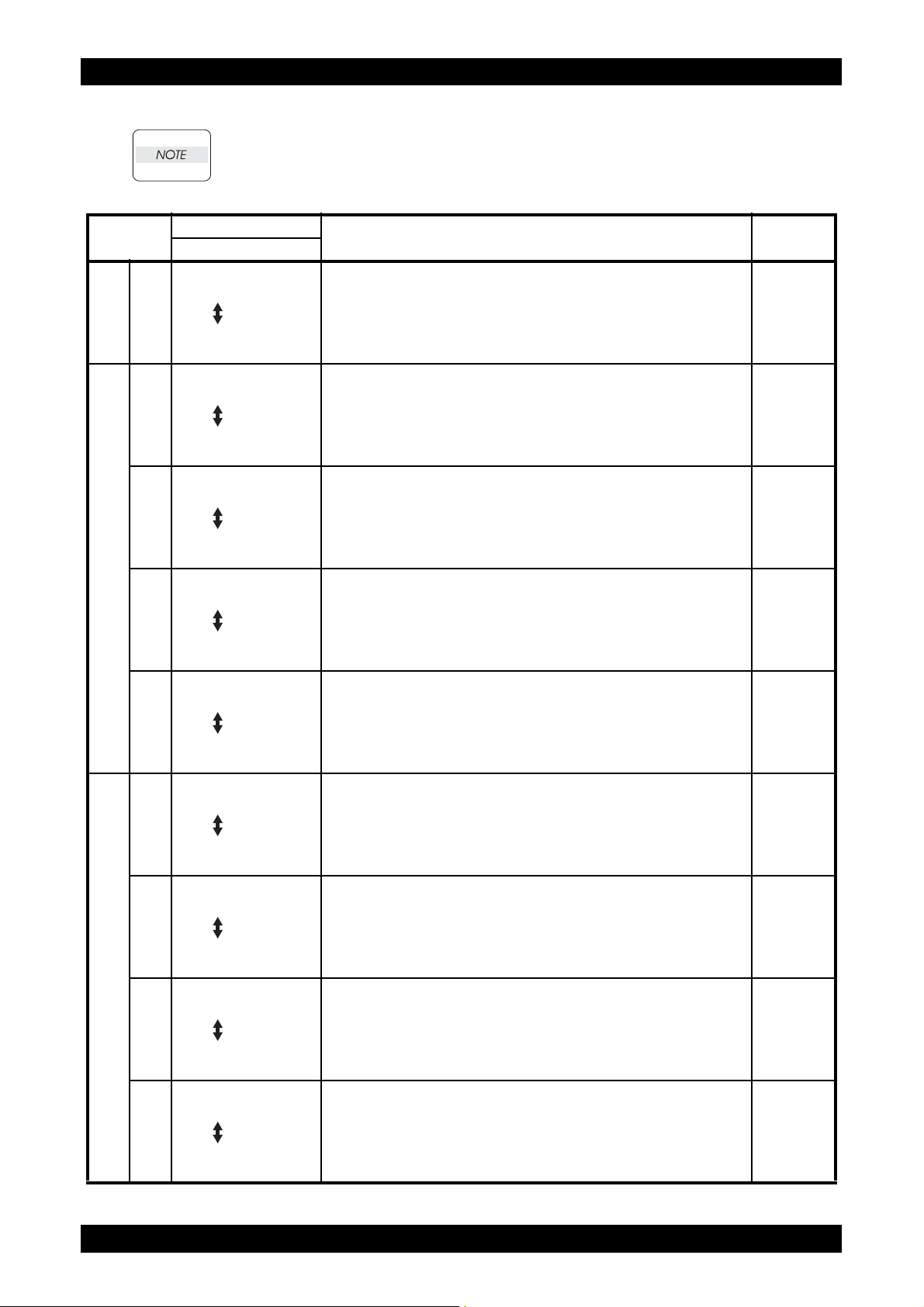
FIP-1.1 004-310: IOT Option Feeder I/F Failure
Revision B
Step Check
Possible causative parts:
HARN ASSY OPTION (PL3.1.20)
PWBA MCU (PL8.2.13)
FEEDER ASSY OPT (PL12.1.3)
HARN ASSY TRAY (PL12.3.23)
Checking the Optional Feeder for installation.
1
Is the Optional Feeder installed correctly?
2 Does the error still occur when printing? Go to step 3. End of work.
Checking the connectors for connection.
Check the connections between the PWBA FEED H and
3
PWBA MCU.
Are P/J27, P/J273, and P/J419 connected surely?
4 Does the error still occur when printing? Go to step 5. End of work.
Checking the HARN ASSY TRAY for continuity.
Disconnect P/J419 from the PWBA FEED H.
5
Disconnect P/J273 from the HARN ASSY OPTION.
Is each cable of P/J419 <=> P/J273 continuous?
Checking the HARN ASSY OPTION for continuity.
Disconnect P/J27 from the PWBA MCU.
6
Disconnect P/J273 from the HARN ASSY TRAY.
Is each cable of P/J27 <=> P/J273 continuous?
Checking after replacing the FEEDER ASSY OPT.
7
Replace the FEEDER ASSY OPT. (Refer to RRP10.1.)
Does the error still occur when the power is turned ON?
Go to step 3.
Go to step 5.
Go to step 6.
Go to step 7.
Replace the
PWBA MCU.
(Refer to RRP8.9.)
Yes No
Remedy
Reseat the
Optional Feeder ,
then go to step 2.
Reconnect the
connector(s)
P/J27, P/J273
and/or P/J419
surely, then go to
step 4.
Replace the
HARN ASSY
TRAY.
Replace the
HARN ASSY
OPTION.
End of work.
Epson AcuLaser C2900N
1 - 25
Confidential
Page 39

Chapter 1 Troubleshooting
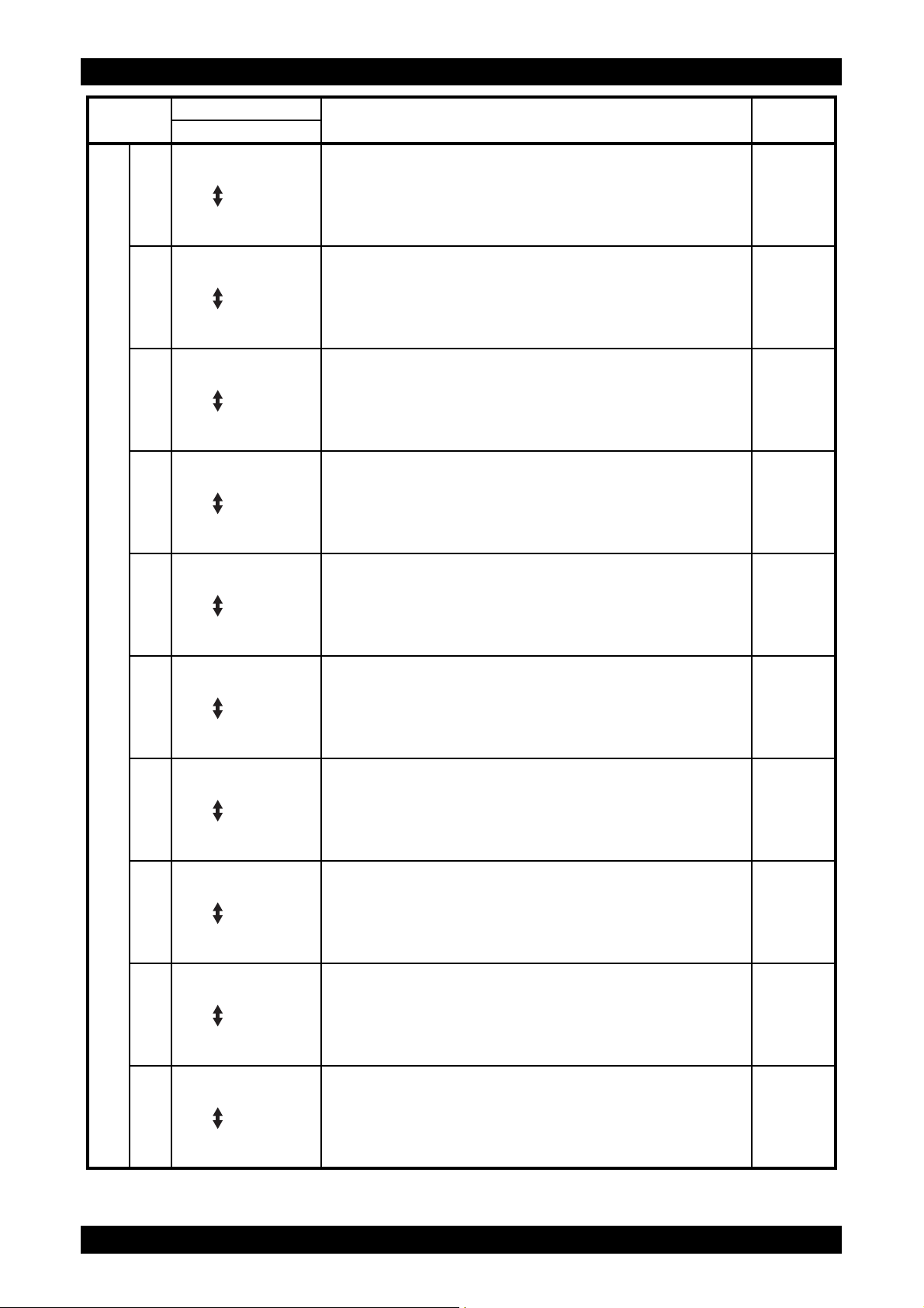
FIP-1.2 010-317: IOT Fuser Unit Detached
Revision B
Step Check
Possible causative parts:
FUSER UNIT (PL6.1.1)
HARNESS ASSY FUSING UNIT MG SFP (PL6.1.2)
PWBA MCU (PL8.2.13)
PWBA LVPS (PL8.2.1)
Checking after resetting the fuser unit
Reseat the fuser unit.
Warning: Start the operation after the fuser unit has
1
cooled down.
Does the error still occur when the power is turned OFF and
ON?
Checking the connectors for connection.
Remove the fuser unit.
Warning: Start the operation after the fuser unit has
cooled down.
Check the connections between the PWBA MCU (P/J17)
and fuser unit (P/J171).
Check the connections between the fuser unit (P/J171) and
PWBA LVPS (P/J47).
Check the connections between the PWBA LVPS (P/J501
and P/J502) and PWBA MCU (P/J14 and P/J15).
Are these connectors connected correctly?
2
Remedy
Yes No
Go to step 2. End of work.
"Reconnect the
connector(s) P/
J17, P/J47, P/
Go to step 4.
J171, P/J501, P/
J502, P/J14 and/
or P/J15 correctly,
then go to step 3."
Does the error still occur when the power is turned OFF and
3
ON?
Checking the HARNESS ASSY FUSING UNIT MG SFP for
continuity.
Disconnect J17 from the PWBA MCU.
4
Disconnect J47 from the PWBA LVPS.
Is each cable of J17 and J47 <=> P171 continuous?
NOTE: P171 is attached to the frame.
Epson AcuLaser C2900N
1 - 26
Go to step 4. End of work.
Replace the
Go to step 5.
HARNESS ASSY
FUSING UNIT MG
SFP.
Confidential
Page 40

Chapter 1 Troubleshooting
Revision B
Step Check
Checking the resistances of Temp. Sensor in the fuser unit.
Remove the fuser unit.
Warning: Start the operation after the fuser unit has
cooled down.
Check the resistances across the following pins of the
removed fuser unit.
J171-5pin <=> J171-4pin
J171-6pin <=> J171-8pin
J171-6pin <=> J171-7pin
Can the resistances be measured? (The resistances are 7
k-ohm at 180 degrees C).
5
Checking after the PWBA LVPS.
Replace the PWBA LVPS. (Refer to RRP8.5.)
6
Does the error still occur when the power is turned off and
on?
Remedy
Yes No
Go to step 6.
Replace the
PWBA MCU.
(Refer to RRP8.9.)
Warning: Start the
operation after the
fuser unit has
cooled down.
Replace the fuser
unit. (Refer to
RRP6.1.) After
replacement, be
sure to clear the
life counter value.
End of work.
Epson AcuLaser C2900N
1 - 27
Confidential
Page 41

Chapter 1 Troubleshooting
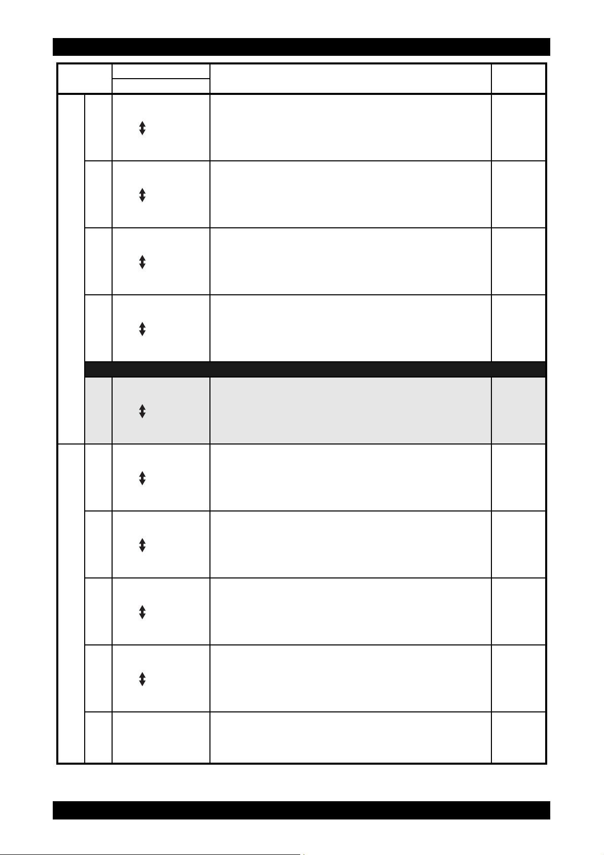
FIP-1.3 010-351: IOT Fuser Unit Life Over
Revision B
Step Check
Possible causative parts:
FUSER UNIT (PL6.1.1)
PWBA MCU (PL8.2.13)
Checking the life counter value of the fuser unit.
1
Does the life counter value show the near of the end?
Checking after resetting the fuser unit.
Reseat the fuser unit.
Warning: Start the operation after the fuser unit has
2
cooled down.
Does the error still occur when the power is turned OFF and
ON?
Checking after replacing the fuser unit.
Replace the fuser unit. (Refer to RRP6.1.)
Warning: Start the operation after the fuser unit has
cooled down.
3
Does the error still occur when the power is turned OFF and
ON?
NOTE: After replacement, be sure to clear the life
counter value.
Remedy
Yes No
Warning: Start the
operation after the
fuser unit has
cooled down.
Replace the fuser
unit. (Refer to
RRP6.1.) After
replacement, be
sure to clear the
life counter value.
Go to step 3. End of work.
Replace the
PWBA MCU.
(Refer to RRP8.9.)
Go to step 2.
End of work.
Epson AcuLaser C2900N
1 - 28
Confidential
Page 42

Chapter 1 Troubleshooting
FIP-1.4 010-397: IOT Fuser Unit Failure
Revision B
Step Check
Possible causative parts:
FUSER UNIT (PL6.1.1)
HARNESS ASSY FUSING UNIT MG SFP (PL6.1.2)
PWBA LVPS (PL8.2.1)
PWBA MCU (PL8.2.13)
HARNESS ASSY LVPS MAIN MG SFP (PL9.1.3)
Does the error still occur when the power is turned OFF and
1
ON?
Checking after resetting the fuser unit.
Reseat the fuser unit.
Warning: Start the operation after the fuser unit has
2
cooled down.
Does the error still occur when the power is turned OFF and
ON?
Checking the connectors for connection.
Remove the fuser unit.
Warning: Start the operation after the fuser unit has
cooled down.
Check the connections between the PWBA MCU (P/J17)
and fuser unit (P/J171).
Check the connections between the fuser unit (P/J171) and
PWBA LVPS (P/J47).
Check the connections between the PWBA LVPS (P/J501
and P/J502) and PWBA MCU (P/J14 and P/J15).
Are these connectors connected correctly?
3
Remedy
Yes No
Go to step 2. End of work.
Go to step 3. End of work.
"Reconnect the
connector(s) P/
J17, P/J47, P/
Go to step 5.
J171, P/J501, P/
J502, P/J14 and/
or P/J15 correctly,
then go to step 4."
Does the error still occur when the power is turned OFF and
4
ON?
Checking the HARNESS ASSY FUSING UNIT MG SFP for
continuity.
Disconnect J17 from the PWBA MCU.
5
Disconnect J47 from the PWBA LVPS.
Is each cable of J17 and J47 <=> P171 continuous?
NOTE: P171 is attached to the frame.
Checking the HARNESS ASSY LVPS MAIN MG SFP for
continuity.
6
Disconnect J14 from the PWBA MCU.
Disconnect J501 from the PWBA LVPS.
Is each cable of J14 <=> J501 continuous?
Epson AcuLaser C2900N
1 - 29
Go to step 5. End of work.
Replace the
Go to step 6.
Go to step 7.
HARNESS ASSY
FUSING UNIT MG
SFP.
Replace the
HARNESS ASSY
LVPS MAIN MG
SFP.
Confidential
Page 43

Chapter 1 Troubleshooting
Revision B
Step Check
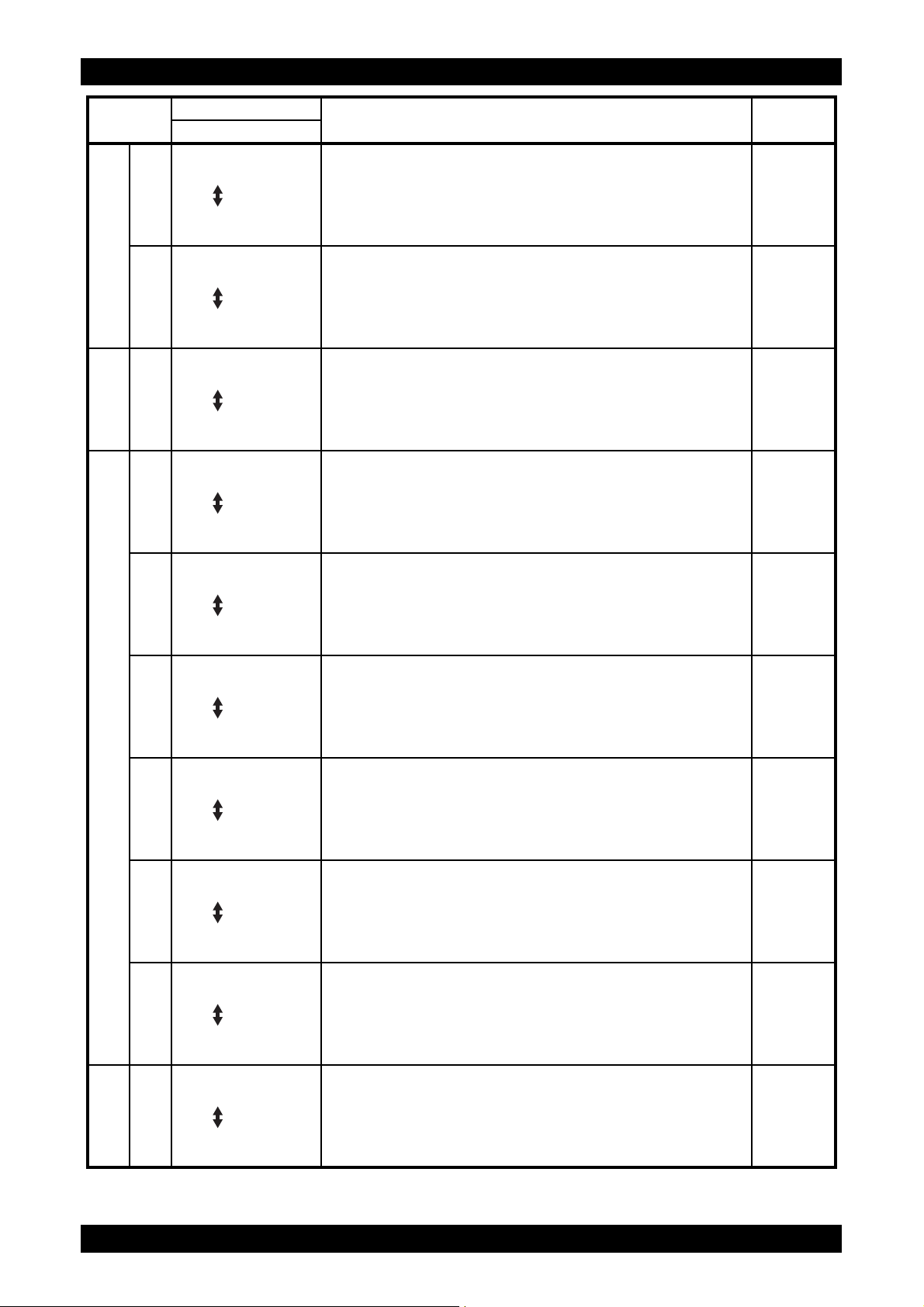
Checking after replacing the fuser unit
Replace the fuser unit. (Refer to RRP6.1.)
Warning: Start the operation after the fuser unit has
cooled down.
7
Does the error still occur when the power is turned OFF and
ON?
NOTE: After replacement, be sure to clear the life
counter value.
Checking after the PWBA LVPS.
Replace the PWBA LVPS. (Refer to RRP8.5.)
8
Does the error still occur when the power is turned off and
on?
Remedy
Yes No
Go to step 8. End of work.
Replace the
PWBA MCU.
(Refer to RRP8.9.)
End of work.
Epson AcuLaser C2900N
1 - 30
Confidential
Page 44

Chapter 1 Troubleshooting
FIP-1.5 010-421: IOT Fuser Unit Near Life
Revision B
Step Check
Possible causative parts:
FUSER UNIT (PL6.1.1)
PWBA MCU (PL8.2.13)
Checking the fuser unit for installation.
Is the fuser unit installed correctly?
1
Warning: Start the operation after the fuser unit has cooled
down.
Does the error still occur when the power is turned OFF and
2
ON?
Checking after replacing the fuser unit.
Replace the fuser unit. (Refer to RRP6.1.)
Warning: Start the operation after the fuser unit has
cooled down.
3
Does the error still occur when the power is turned OFF and
ON?
NOTE: After replacement, be sure to clear the life
counter value.
Remedy
Yes No
Reseat the fuser
Go to step 3.
Go to step 3. End of work.
Replace the
PWBA MCU.
(Refer to RRP8.9.)
unit, then go step
2.
End of work
Epson AcuLaser C2900N
1 - 31
Confidential
Page 45

Chapter 1 Troubleshooting
Revision B
FIP-1.6 016-500 / 016-501 / 016-502 / 116-315 / 116-317 / 116-323 / 116-324 / 116-326 /
116-327 / 116-328 / 116-343 / 116-350 / 116-390: ESS Error
Step Check
Possible causative parts:
PWBA ESS SFP (PL8.1.7)
Does the error still occur when the power is turned OFF and
1
ON?
Remedy
Yes No
Replace the
PWBA ESS SFP.
(Refer to RRP8.3.)
End of work.
Epson AcuLaser C2900N
1 - 32
Confidential
Page 46

Chapter 1 Troubleshooting
FIP-1.7 016-520: Ipsec Certificate Error
Revision B
Step Check
Possible causative parts:
PWBA ESS SFP (PL8.1.7)
PWBA MCU (PL8.2.13)
Does the error still occur when the power is turned OFF
1
and ON?
Checking after replacing the PWBA ESS SFP.
Replace the PWBA ESS SFP. (Refer to RRP8.3.)
2
Does the error still occur when the power is turned off and
on?
Remedy
Yes No
Go to step 2. End of work.
Replace the
PWBA MCU.
(Refer to RRP8.9.)
End of work.
Epson AcuLaser C2900N
1 - 33
Confidential
Page 47

Chapter 1 Troubleshooting
FIP-1.8 016-718: Memory Over flow
Revision B
Step Check
Possible causative parts:
MEMORY CARD (OPTION) (PL8.1.15)
Checking for memory expansion.
1
Is additional memory installed?
Is the additional memory installed properly?
Checking after setting the Print Mode to "Standard" via the
printer driver Set the Print Mode of the printer driver to
2
"Standard".
Does the error persist during printing?
Deleting the data by executing Clear Storage. Execute
3
"Clear Storage"under [Maintenance] in the Control Panel.
Does the error persist during printing?
Remedy
Yes No
Install additional
Go to step 2.
Go to step 3. End of work.
The current
printing job
process cannot be
continued
because the
memory capacity
is exceeded.
memory. Or, reinstall it properly.
End of work.
Epson AcuLaser C2900N
1 - 34
Confidential
Page 48

Chapter 1 Troubleshooting
FIP-1.9 016-720: PDL Error
Revision B
Step Check
Possible causative parts:
PWBA ESS SFP (PL8.1.7)
Checking cable plug/unplug.
1
Plug and unplug the cable. (USB cable or I/F cable)
Does the error still occur when printing?
Checking after replacing the Cable.
Replace the cable. (USB cable or I/F cable)
2
Does the error still occur when the power is turned off and
on?
Remedy
Yes No
Go to step 2. End of work.
Replace the
PWBA ESS SFP.
(Refer to RRP8.3.)
End of work.
Epson AcuLaser C2900N
1 - 35
Confidential
Page 49

Chapter 1 Troubleshooting
Revision B
FIP-1.10 016-737 / 016-741 / 016-742 / 016-743 / 016-744 / 016-745: Download Format
Error / Download Protect Error / Download ID Error / Download Range Error /
Download Check Sum Error / Download header Error
Step Check
Possible causative parts:
PWBA ESS SFP (PL8.1.7)
Checking the download file.
1
Was the file for C2900 downloaded?
Checking the connection between PC and printer.
Are your PC and the printer correctly connected by USB or
LAN?
2
Disconnect and reconnect the USB or network cable.
Does the error still occur when the power is turned OFF and
ON?
Checking after reseating the PWBA ESS SFP.
Reseat the PWBA ESS SFP.
3
Does the error still occur when the power is turned OFF and
ON?
Checking re-downloading the correct file for C2900.
Re-download the correct file from web site.
4
Does the error still occur when the power is turned OFF and
ON?
Remedy
Yes No
Go to step 2.
Go to step 3. End of work.
Go to step 4. End of work.
Replace the
PWBA ESS SFP.
(Refer to RRP8.3.)
Re-download the
correct file.
End of work.
Epson AcuLaser C2900N
1 - 36
Confidential
Page 50

Chapter 1 Troubleshooting
FIP-1.11 016-753 / 016-755: PDF password error / PDF print disabled error
Revision B
Step Check
Possible causative parts:
Checking the PDF data.
-Enter the correct PDF document password again.
1
-Change the PDF document security setting.
Does the error still occur when printing?
Yes No
End of work.
Remedy
Upgrade the
firmware.
Epson AcuLaser C2900N
1 - 37
Confidential
Page 51

Chapter 1 Troubleshooting
FIP-1.12 016-757: Auditron - Invalid User
Revision B
Step Check
Possible causative parts:
Checking the user‘s account setting.
1
Set the correct user‘s account (user name and password).
Does the error still occur when printing?
Yes No
End of work.
Remedy
Upgrade the
firmware.
Epson AcuLaser C2900N
1 - 38
Confidential
Page 52

Chapter 1 Troubleshooting
FIP-1.13 016-758: Auditron - Disabled Function
Revision B
Step Check
Possible causative parts:
Checking the “Black&White” setting.
1
Set the [Color Mode] to the [Color].
Does the error still occur when printing?
Yes No
End of work.
Remedy
Upgrade the
firmware.
Epson AcuLaser C2900N
1 - 39
Confidential
Page 53

Chapter 1 Troubleshooting
FIP-1.14 016-759: Auditron - Reached Limit
Revision B
Step Check
Possible causative parts:
Checking the “Color Track” setting.
Set the correct value of [User Registration] exceed the
1
limitation.
Does the error still occur when printing?
Yes No
End of work.
Remedy
Upgrade the
firmware.
Epson AcuLaser C2900N
1 - 40
Confidential
Page 54

Chapter 1 Troubleshooting
FIP-1.15 016-799: Job Environment Violation
Revision B
Step Check
Possible causative parts:
PWBA ESS SFP (PL8.1.7)
Checking the paper size.
1
Does the paper size in use meet the specifications?
2 Does the error still occur when printing? Go to step 3. End of work.
Checking the paper size setup.
3
Does the using paper size match the printer setup value?
Setup the paper size through your PC.
4
Does the error still occur when printing?
Checking the printing job.
5
Does the error still occur when printing the Windows test
print?
Checking the firmware version.
6
Is the firmware the latest version?
Go to step 3.
Go to step 5. Go to step 4.
Go to step 5. End of work.
Go to step 6.
Replace the
PWBA ESS SFP.
(Refer to RRP8.3.)
Yes No
Remedy
Use the paper that
meets the
specifications,
then go to step 2.
End of work.
Upgrade the
firmware.
Epson AcuLaser C2900N
1 - 41
Confidential
Page 55

Chapter 1 Troubleshooting
FIP-1.16 016-982: Disc Full
Revision B
Step Check
Possible causative parts:
PWBA ESS SFP (PL8.1.7)
MEMORY CARD (OPTION) (PL8.1.15)
Checking the file data in the printer.
1
Print or clear the stored files and data at the prin ter memo ry.
Does the error still occur when printing?
Checking the memory capacity for print.
2
Print the small size file (like a Windows test page).
Does the error still occur when printing?
3 Is the customer using the recommended memory card? Go to step 4.
Checking the MEMORY CARD (OPTION) installation.
4
Reseat the MEMORY CARD (OPTION).
Does the error still occur when turning on the power?
Checking after resetting the MEMORY CARD (OPTION).
5
Replace the MEMORY CARD. (Refer to RRP8.4.)
Does the error still occur when turning on the power?
Go to step 2. End of work.
Go to step 3.
Go to step 5. End of work.
Replace the
PWBA ESS SFP.
(Refer to RRP8.3.)
Yes No
Remedy
Add the MEMORY
CARD or divide
the printing job.
Replace to the
recommended
memory card.
End of work.
Epson AcuLaser C2900N
1 - 42
Confidential
Page 56

Chapter 1 Troubleshooting
FIP-1.17 024-340: IOT Firmware Error
Revision B
Step Check
Possible causative parts:
PWBA MCU (PL8.2.13)
Does the error still occur after several ON/OFF procedures
1
of the power?
Checking the firmware version.
2
Is the firmware the latest version?
Checking after resetting the PWBA MCU.
Reseat the PWBA MCU.
3
Does the error still occur when the power is turned OFF and
ON?
Checking after replacing the PWBA MCU.
Replace the PWBA MCU. (Refer to RRP8.9.)
4
Does the error still occur when the power is turned OFF and
ON?
*1: Though some kind of foreign noise would be possible cause, go to FIP Electrical Noise in Other FIP
and check, to make sure.
Go to step 2. End of work. *1
Go to step 3.
Go to step 4. End of work. *1
Go to Electrical
Noise.
Yes No
Remedy
Upgrade the
firmware, then go
to step 3.
End of work.
Epson AcuLaser C2900N
1 - 43
Confidential
Page 57

Chapter 1 Troubleshooting
FIP-1.18 024-360: MCU DownLoad Error
Revision B
Step Check
Possible causative parts:
PWBA MCU (PL8.2.13)
Download the Firmware using the download mode.
(Refer to "1.2 Firmware version up procedure using the
download mode" of "Appendix_1 Firmware download".)
1
Does the error still occur when the power is turned off and
on?
Remedy
Yes No
Replace the
PWBA MCU
(Refer to RRP8.9).
End of work.
Epson AcuLaser C2900N
1 - 44
Confidential
Page 58

Chapter 1 Troubleshooting
FIP-1.19 024-362: IOT Start Image Marking Time-out
Revision B
Step Check
Possible causative parts:
PWBA ESS SFP (PL8.1.7)
Checking the firmware version.
1
Is the firmware the latest version?
Checking the error.
2
Does the error still occur when printing?
Remedy
Yes No
Go to step 2.
Replace the
PWBA ESS SFP.
(Refer to RRP8.3.)
Upgrade the
firmware, then go
step 2.
End of work.
Epson AcuLaser C2900N
1 - 45
Confidential
Page 59

Chapter 1 Troubleshooting
FIP-1.20 024-371: MCU-ESS Communication Fail
Revision B
Step Check
Possible causative parts:
PWBA ESS SFP (PL8.1.7)
PWBA MCU (PL8.2.13)
HARNESS ASSY ESS MG SFP (PL9.1.1)
Checking after resetting the PWBA ESS SFP and PWBA
MCU.
1
Reseat the PWBA ESS SFP and PWBA MCU.
Does the error still occur when the power is turned OFF and
ON?
Checking the connectors for connection.
Check the connections between the PWBA MCU and
PWBA ESS SFP.
Are P/J10 and P/J101 connected correctly?
2
Remedy
Yes No
Go to step 2. End of work.
Reconnect the
connector(s) P/
Go to step 4.
J10 and/or P/J101
correctly, then go
to step 3.
Does the error still occur when the power is turned OFF and
3
ON?
Checking the HARNESS ASSY ESS MG SFP for continuity.
Disconnect J10 from the PWBA MCU.
4
Disconnect J101 from the PWBA ESS SFP.
Is each cable of J10 <=> J101 continuous?
Checking the firmware version
5
Is the firmware the latest version?
Checking after replacing the PWBA MCU.
Replace the PWBA MCU. (Refer to RRP8.9.)
6
Does the error still occur when the power is turned OFF and
ON?
Go to step 4. End of work.
Replace the
Go to step 5.
Go to step 6.
Replace the
PWBA ESS SFP.
(Refer to RRP8.3.)
HARNESS ASSY
ESS MG SFP.
Upgrade the
firmware.
End of work.
Epson AcuLaser C2900N
1 - 46
Confidential
Page 60

Chapter 1 Troubleshooting
Revision B
FIP-1.21 024-985: Waiting for "Continue" key to be pressed after reloading paper to the
SSI
Step Check
Possible causative parts:
PWBA ESS SFP (PL8.1.7)
Checking the firmware version.
1
Is the firmware the latest version?
Remedy
Yes No
Replace the
PWBA ESS SFP.
(Refer to RRP8.3.)
Upgrade the
firmware.
Epson AcuLaser C2900N
1 - 47
Confidential
Page 61

Chapter 1 Troubleshooting
FIP-1.22 027-446 / 027-452: IPv6 duplicate / IPv4 duplicate
Revision B
Step Check
Possible causative parts:
Checking the IP addresses.
Remove the duplicate IP addresses.
1
Does the error still occur when the power is turned off and
on?
Yes No
End of work.
Remedy
Upgrade the
firmware.
Epson AcuLaser C2900N
1 - 48
Confidential
Page 62

Chapter 1 Troubleshooting
FIP-1.23 041-340: IOT NVRAM Error
If the error occurred after replacing the PWBA MCU, transfer the internal data of the old
PWBA MCU to a new one.
Revision B
Step Check
Possible causative parts:
DRUM CARTRIDGE (PL4.1.21)
PWBA MCU (PL8.2.13)
HARN ASSY PHD XPRO (PL9.1.11)
Does the error still occur after several ON/OFF procedures
1
of the power?
Checking after resetting the DRUM CARTRIDGE and
TONER CARTRIDGEs.
Reseat the DRUM CARTRIDGE and four TONER
2
CARTRIDGEs.
Does the error still occur when the power is turned OFF and
ON?
Checking after resetting the PWBA MCU.
Reseat the PWBA MCU.
3
Does the error still occur when the power is turned OFF and
ON?
Checking the connectors for connection.
Check the connections between the PWBA EEPROM and
4
PWBA MCU.
Are P/J 144, and P/J 42 connected surely?
Does the error still occur when the power is turned OFF and
5
ON?
Checking the HARN ASSY PHD XPRO for continuity.
Disconnect J42 from the PWBA MCU.
6
Disconnect J144 from the PWBA EEPROM (XPRO).
Is each cable of J42 <=> J144 continuous?
Checking after replacing the PWBA MCU.
Replace the PWBA MCU. (Refer to RRP8.9.)
7
Does the error still occur when the power is turned OFF and
ON?
Remedy
Yes No
Go to step 2. End of work. *1
Go to step 3. End of work. *1
Go to step 4. End of work. *1
Reconnect the
connector(s) P/
Go to step 6.
Go to step 6. End of work.
Go to step 7.
Go to Electrical
Noise.
J42 and P/J144
surely, then go to
step 5.
Replace the
HARN ASSY PHD
XPRO.
End of work.
*1: Though some kind of foreign noise would be possible cause, go to FIP Electrical Noise in Other FIP
and check, to make sure.
Epson AcuLaser C2900N
1 - 49
Confidential
Page 63

Chapter 1 Troubleshooting
FIP-1.24 042-313: IOT Fan Motor Failure
Revision B
Step Check
Possible causative parts:
FAN (PL8.1.1)
PWBA LVPS (PL8.2.1)
PWBA MCU (PL8.2.13)
HARNESS ASSY LVPS MAIN MG SFP (PL9.1.3)
Does the error still occur when the power is turned OFF and
1
ON?
Checking the FAN for rotation.
Does the FAN function normally?
2
Checked by [Digital Output] - [Main Motor or Fan Motor] in
[IOT Diag] of diagnosis.
During this check, close the COVER ASSY FRONT MG.
Check the connection between the FAN and the PWBA
3
LVPS.
Is P/J503 on the PWBA LVPS connected correctly?
Does the error still occur when the power is turned OFF and
4
ON?
Check the connections between the PWBA LVPS and
PWBA MCU.
Are P/J501 and P/J14 connected correctly?
Remedy
Yes No
Go to step 2. End of work.
Replace the
PWBA MCU.
(Refer to RRP8.9.)
Go to step 5.
Go to step 5. End of work.
Go to step 3.
Reconnect the
connector P/J 503
correctly, then go
to step 4.
5
Does the error still occur when the power is turned OFF and
6
ON?
Checking the HARNESS ASSY LVPS MAIN MG SFP for
continuity.
7
Disconnect J501 from the PWBA LVPS.
Disconnect J14 from the PWBA MCU.
Is each cable of J501 <=> J14 continuous?
Reconnect the
connector(s) P/
Go to step 7.
Go to step 7. End of work.
Go to step 8.
J501 and P/J14
correctly, then go
to step 6.
Replace the
HARNESS ASSY
LVPS MAIN MG
SFP.
Epson AcuLaser C2900N
1 - 50
Confidential
Page 64

Chapter 1 Troubleshooting
Revision B
Step Check
Checking the power to the FAN.
Disconnect J503 from the PWBA LVPS.
Is the voltage across P503-1pin <=> ground on the PWBA
LVPS, about +24 VDC when the interlock switch (HARN
ASSY INTERLOCK) is pushed?
8
Checking after replacing the PWBA LVPS.
Replace the PWBA LVPS. (Refer to RRP8.5.)
9
Does the error still occur when the power is turned OFF and
ON?
Remedy
Yes No
Replace the FAN.
(Refer to RRP8.1.)
Replace the
PWBA MCU.
(Refer to RRP8.9.)
Go to step 9.
End of work.
Epson AcuLaser C2900N
1 - 51
Confidential
Page 65

Chapter 1 Troubleshooting
FIP-1.25 042-325: IOT Main Motor Failure
Revision B
Step Check
Possible causative parts:
DRIVE ASSY MAIN (PL7.1.2)
PWBA MCU (PL8.2.13)
HARNESS ASSY MAIN MOT MG SFP (PL9.1.7)
Does the error occur when the power is turned OF F and
1
ON?
Checking after resetting the DRUM CARTRIDGE.
Reseat the DRUM CARTRIDGE.
2
Does the error still occur when the power is turned OFF and
ON?
Checking the Main Motor for rotation.
Does the Main Motor function normally?
- PC Operation :
Checked by [Main Motor Operation Check] of the [Machine
3
Check] in Tool Box.
- Panel Operation :
Checked by [Digital Output] - [Main Motor] of [IOT Diag] in
diagnosis.
Checking the connectors of the MAIN MOTOR for
connection.
Check the connections between the PWBA MCU and
DRIVE ASSY MAIN.
Are P/J21 and P/J211 connected correctly?
4
Remedy
Yes No
Go to step 2. End of work.
Go to step 3. End of work.
Replace the
PWBA MCU.
(Refer to RRP8.9.)
Go to step 6.
Go to step 4.
Reconnect the
connector(s) P/
J21 and/or P/J211
correctly, then go
to step 5.
Does the error still occur when the power is turned OFF and
5
ON?
Checking the HARNESS ASSY MAIN MOT MG SFP for
continuity.
6
Disconnect J21 from the PWBA MCU.
Disconnect J211 from the DRIVE ASSY MAIN.
Is each cable of J21 <=> J211 continuous?
Checking after resetting the DRIVE ASSY MAIN.
Reseat the DRIVE ASSY MAIN.
7
Does the error still occur when the power is turned OFF and
ON?
Checking the power to the DRIVE ASSY MAIN.
Disconnect J21 from the PWBA MCU.
8
Are the voltages across J21-2pin/J21-4pin <=> ground on
the PWBA MCU, about +24 VDC when the interlock switch
(HARN ASSY INTERLOCK) is pushed?
Epson AcuLaser C2900N
1 - 52
Go to step 6. End of work.
Replace the
Go to step 7.
Go to step 8. End of work.
Replace the
DRIVE ASSY
MAIN. (Refer to
RRP7.2.)
HARNESS ASSY
MAIN MOT MG
SFP.
Replace the
PWBA MCU.
(Refer to RRP8.9.)
Confidential
Page 66

Chapter 1 Troubleshooting
FIP-1.26 042-326: IOT Sub Motor Failure
Revision B
Step Check
Possible causative parts:
DRIVE ASSY SUB (PL7.1.1)
PWBA MCU (PL8.2.13)
HARNESS ASSY SUB MOT MG SFP (PL9.1.8)
Does the error still occur when the power is turned OFF and
1
ON?
Checking after resetting the fuser unit and DRUM
CARTRIDGE
Reseat the fuser unit and DRUM CARTRIDGE.
Warning: Start the operation after the fuser unit has
2
cooled down.
Does the error still occur when the power is turned OFF and
ON?
Checking the Sub Motor for rota tion.
Does the Sub Motor function normally?
- PC Operation :
Checked by [Fuser Motor Operation Check] of the [Machine
3
Check] in Tool Box.
- Panel Operation : Checked by [Digital Output] - [Sub
Motor] of [IOT Diag] in diagnosis.
Checking the connectors of the SUB MOTOR for
connection.
Check the connections between the PWBA MCU and
DRIVE ASSY SUB.
Are P/J22 and P/J221 connected correctly?
4
Remedy
Yes No
Go to step 2. End of work.
Go to step 3. End of work.
Replace the
PWBA MCU.
(Refer to RRP8.9.)
Go to step 6.
Go to step 4.
Reconnect the
connector(s) P/
J22 and/or P/J221
correctly, then go
to step 5.
Does the error still occur when the power is turned OFF and
5
ON?
Checking the HARNESS ASSY SUB MOT MG SFP for
continuity.
6
Disconnect J22 from the PWBA MCU.
Disconnect J221 from the DRIVE ASSY SUB.
Is each cable of J22 <=> J221 continuous?
Checking after resetting the DRIVE ASSY SUB.
Reseat the DRIVE ASSY SUB.
7
Does the error still occur when the power is turned OFF and
ON?
Checking the power to the DRIVE ASSY SUB.
Disconnect J22 from the PWBA MCU.
8
Are the voltages across J22-2pin/J22-4pin <=> ground on
the PWBA MCU, about +24 VDC when the interlock switch
(HARN ASSY INTERLOCK) is pushed?
Epson AcuLaser C2900N
1 - 53
Go to step 6. End of work.
Replace the
Go to step 7.
Go to step 8. End of work.
Replace the
DRIVE ASSY
SUB. (Refer to
RRP7.1.)
HARNESS ASSY
SUB MOT MG
SFP.
Replace the
PWBA MCU.
(Refer to RRP8.9.)
Confidential
Page 67

Chapter 1 Troubleshooting
FIP-1.27 042-372 / 042-373: IOT K Mode Solenoid Error 1/2
Revision B
Step Check
Possible causative parts:
DRIVE ASSY PH (PL7.1.4)
PWBA MCU (PL8.2.13)
HARN ASSY KSNR REGCL (PL9.1.9)
Does the error still occur when the power is turned OFF and
1
ON?
Checking the K Mode Solenoid (Color Mode Switching
Solenoid) for operation.
Does the K Mode Solenoid function normally?
Checked by [Digital Output] - [K Mode Solenoid] in [IOT
Diag] of diagnosis.
2
During this check, close the COVER ASSY FRONT MG.
Does the K Mode Solenoid click sound arise from the
DRIVE ASSY PH, when the K Mode Solenoid check is
performed?
Checking after resetting the DRIVE ASSY PH.
Reseat the DRIVE ASSY PH.
3
Does the error still occur when the power is turned OFF and
ON?
Checking the connector of the K Mode Solenoid in the
DRIVE ASSY PH for connection.
Check the connection between the PWBA MCU and K
Mode Solenoid.
Is P/J24 connected correctly?
Remedy
Yes No
Go to step 2. End of work.
Go to step 3. Go to step 4.
Go to step 8. End of work.
4
Does the error still occur when the power is turned OFF and
5
ON?
Checking the power to the K Mode Solenoid.
Disconnect J24 from the PWBA MCU.
6
Is the voltage across P24-1pin <=> ground on the PWBA
MCU, about +24 VDC when the Interlock Switch (HARN
ASSY INTERLOCK) is pushed?
Checking the K Mode Solenoid for resistance.
Disconnect P/J24 from the PWBA MCU.
7
Is the resistance across J24-1 and J24-2 about 80 to 110ohm?
Reconnect the
Go to step 6.
Go to step 6. End of work.
Go to step 7.
Replace the
PWBA MCU.
(Refer to RRP8.9.)
connector P/J24
correctly, then go
to step 5.
Replace the
PWBA MCU.
(Refer to RRP8.9.)
Replace the
DRIVE ASSY PH.
(Refer to RRP7.3.)
Epson AcuLaser C2900N
1 - 54
Confidential
Page 68

Chapter 1 Troubleshooting
Revision B
Step Check
Checking the connectors of the K Mode Sensor in the
DRIVE ASSY PH for connection
Check the connections between the PWBA MCU and K
Mode Sensor.
Are P/J26 and P/J261 connected correctly?
8
Does the error still occur when the power is turned OFF and
9
ON?
Checking the HARN ASSY KSNR REGCL for continuity.
Disconnect J26 from the PWBA MCU.
10
Disconnect J261 from the K Mode Sensor.
Is each cable of J26 <=> J261 continuous?
Checking the power to the K Mode Sensor.
Disconnect J26 from the PWBA MCU.
11
Is the voltage across P26-1pin <=> ground on the PWBA
MCU, about +3.3 VDC?
Checking the K Mode Sensor for operation.
Remove the DRIVE ASSY PH from the printer once, but P/
J261 and P/J24 should be connected.
Checked by [Digital Input] - [DI-04] in [IOT Diag] of
12
diagnosis.
During this check, close the COVER ASSY FRONT MG.
Does the status (L or H) change, when a piece of paper is
inserted into the gap of the K Mode Sensor?
Remedy
Yes No
Reconnect the
connector(s) P/
Go to step 10.
Go to step 10. End of work.
Go to step 11.
Go to step 12.
Replace the
PWBA MCU.
(Refer to RRP8.9.)
J26 and/or P/
J261correctly,
then go to step 9.
Replace the
HARN ASSY
KSNR REGCL.
Replace the
PWBA MCU.
(Refer to RRP8.9.)
Replace the
DRIVE ASSY PH.
(Refer to RRP7.3.)
Epson AcuLaser C2900N
1 - 55
Confidential
Page 69

Chapter 1 Troubleshooting
FIP-1.28 042-700:IOT Over Heat Stop
Revision B
Step Check
Possible causative parts:
SENSOR HUM (PL8.2.7)
PWBA MCU (PL8.2.13)
HARN ASSY HUM (PL9.1.6)
Checking the connectors for connection.
Check the connections between the PWBA MCU and
1
SENSOR HUM.
Are P/J20 and P/J201 connected surely?
Does the error still occur when the power is turned off and
2
on?
Checking the HARN ASSY HUM for continuity.
Disconnect P/J20 from the PWBA MCU.
3
Disconnect P/J201 from the SENSOR HUM.
Is each cable of P/J20 <=> P/J201 continuous?
Checking the output power of SENSOR HUM.
Disconnect P/J20 on the PWBA MCU.
4
Is the voltage across ground <=> J20-4pin on the PWBA
MCU, about +5VDC?
Remedy
Yes No
Reconnect the
connector(s) P/
Go to step 3.
Go to step 3. End of work.
Go to step 4.
Replace the
SENSOR HUM.
(Refer to RRP8.7.)
J20 and/or P/
J201 surely, then
go to step 2
Replace the
HARN ASSY
HUM.
Replace the
PWBA MCU.
(Refer to RRP8.9.)
Epson AcuLaser C2900N
1 - 56
Confidential
Page 70

Chapter 1 Troubleshooting
FIP-1.29 061-370: IOT ROS Failure
Revision B
Step Check
Possible causative parts:
ROS ASSY (PL4.1.1)
HARN ASSY ROS RE (PL4.1.22)
HARN ASSY ROS VIDEO (PL4.1.23)
PWBA MCU (PL8.2.13)
Does the error still occur when the power is turned OFF
1
and ON?
Checking after resetting the PWBA MCU.
Reseat the PWBA MCU.
2
Does the error still occur when the power is turned OFF
and ON?
Checking after resetting the ROS ASSY.
Reseat the ROS ASSY.
3
Does the error still occur when the power is turned OFF
and ON?
Check the connections between the ROS ASSY and
PWBA MCU.
Are P/J40, P/J41, P/J411 and P/J412 connected correctly?
4
Remedy
Yes No
Go to step 2. End of work.
Go to step 3. End of work.
Go to step 4. End of work.
Reconnect the
connector(s) P/
Go to step 6.
J40, P/J41, P/J41 1
and/or P/J412
correctly, then go
to step 5.
Does the error still occur when the power is turned OFF
5
and ON?
Checking the HARN ASSY ROS RE for continuity.
Disconnect P/J40 from the PWBA MCU.
6
Disconnect P/J411 from the ROS ASSY.
Is each cable of J40 <=> J411 continuous?
Checking the HARN ASSY ROS VIDEO for continuity.
Disconnect J41 from the PWBA MCU.
7
Disconnect J412 from the ROS ASSY .
Is each cable of J41 <=> J412 continuous?
Checking after replacing the ROS ASSY.
Replace the ROS ASSY. (Refer to RRP4.1.)
8
Does the error still occur when the power is turned OFF
and ON?
Go to step 6. End of work.
Replace the
Go to step 7.
Go to step 8.
Replace the
PWBA MCU.
(Refer to RRP8.9.)
HARN ASSY ROS
RE.
Replace the
HARN ASSY ROS
VIDEO.
End of work.
Epson AcuLaser C2900N
1 - 57
Confidential
Page 71

Chapter 1 Troubleshooting
FIP-1.30 071-100: IOT Tray1 Misfeed JAM
Revision B
Step Check
Possible causative parts:
CASSETTE ASSY 250 (PL2.1.1)
HOLDER ASSY RETARD (PL2.1.5)
CLUTCH ASSY DRV (PL3.1.1)
SOLENOID FEED MSI (PL3.1.11)
HARN ASSY L SIDE (PL3.1.18)
ROLL ASSY FEED (PL3.2.4)
ACTUATOR REGI ROLL M (PL3.2.8)
ACTUATOR REGI IN (PL3.2.11)
SENSOR PHOTO (PL3.2.13)
DRIVE ASSY MAIN (PL7.1.2)
DRIVE ASSY PH (PL7.1.4)
PWBA MCU (PL8.2.13)
HARNESS ASSY MAIN MOT MG SFP (PL9.1.7)
HARN ASSY KSNR REGCL (PL9.1.9)
Replace the paper
Checking the paper condition.
1
Is the paper in the Tray 1 wrinkled or damaged?
2 Does the error still occur when printing? Go to step 3. End of work.
Checking after reloading a new paper.
3
Reload a new paper in the Tray 1.
Does the error still occur when printing?
Checking the COVER ASSY FRONT MG for latching.
Open and close the COVER ASSY FRONT MG, and then
4
latch correctly.
Does the error still occur when printing?
Checking the Main Motor (DRIVE ASSY MAIN) for
operation.
Does the Main Motor (DRIVE ASSY MAIN) operate
properly?
5
Checked by [Digital Output] - [Main Motor] in [IOT Diag] of
diagnosis.
During this check, close the COVER ASSY FRONT MG.
Checking the DRIVE ASSY PH for operation.
Does the ROLL ASSY FEED, ROLL ASSY REGI and ROLL
REGI METAL rotate properly?
Checked by [Digital Output] - [Regi Clutch] in [IOT Diag] of
6
diagnosis.
During this check, cheat the interlock switch (HARN ASSY
INTERLOCK).
Checking the paper feeding position.
7
Is the paper not fed from the Tray 1?
Checking after resetting the Guide Sides and End Guide on
the Tray 1.
8
Reset the Guide Sides and End Guide, and reseat the Tray
1 to the printer correctly.
Does the error still occur when printing?
Checking the HOLDER ASSY RETARD on the Tray 1 for
shape and rotation.
9
Pull the Tray 1 out from the printer.
Is the HOLDER ASSY RETARD not contaminated and/or
damaged, and rotated smoothly?
with a new and dry
one, then go to
step 2.
Go to step 4. End of work.
Go to step 5. End of work.
Go to step 6. Go to step 19.
Go to step 7.
Go to step 8. Go to step 12.
Go to step 9. End of work.
Go to step 10.
Yes No
Remedy
Go to step 3.
Reseat or replace
the DRIVE ASSY
PH. (Refer to
RRP7.3.)
Replace the
HOLDER ASSY
RETARD.
(Refer to RRP2.2.)
Epson AcuLaser C2900N
1 - 58
Confidential
Page 72

Chapter 1 Troubleshooting
Revision B
Step Check
Checking the ROLL ASSY FEED for shape and rotation.
Pull the Tray 1 out from the printer.
10
Is the ROLL ASSY FEED not contaminated and/or
damaged, and rotated smoothly?
Checking the Tray 1 Feed Solenoid (SOLENOID FEED
MSI) for operation.
Does the Tray 1 Feed Solenoid (SOLENOID FEED MSI)
operate properly?
11
Check by [Digital Output] - [Tray1 Feed Solenoid] in [IOT
Diag] of diagnosis.
During this check, cheat the interlock switch (HARN ASSY
INTERLOCK).
Checking the paper lead edge staying position.
12
Does the paper lead edge stay before the ROLL ASSY
REGI and ROLL REGI METAL?
Checking the paper transfer path between the ROLL ASSY
13
FEED and ROLL ASSY REGI.
Are there any obstacles on the paper transfer path?
Checking the ACTUATOR REGI IN for shape and operation.
Remove the CHUTE ASSY LOW (PL3.2.27) once to check
14
the shape and operation.
Are the shape and operation of the ACTUATOR REGI IN
normal?
Checking the Regi. Sensor (SENSOR PHOTO) for
operation.
Does the number on the screen increase by one, when the
actuator (ACTUATOR REGI IN) is operated?
15
Remove the CHUTE ASSY LOW (PL3.2.27) once to check
the operation.
Checked by [Digital Input] - [Regi Sensor] in [IOT Diag] of
diagnosis.
Checking the Regi. Clutch (CLUTCH ASSY DRV) for
operation, and ROLL ASSY REGI and ROLL REGI METAL
for rotation.
Checked by [Digital Output] - [Regi Clutch] in [IOT Diag] of
diagnosis.
16
Does the Regi. Clutch (CLUTCH ASSY DRV) operate
properly, and the ROLL ASSY REGI and ROLL REGI
METAL rotate?
During this check, cheat the interlock switch (HARN ASSY
INTERLOCK).
Checking the ACTUATOR REGI ROLL M for shape and
operation.
Remove the CHUTE ASSY LOW (PL3.2.27) once to check
17
the shape and operation.
Are the shape and operation of the ACTUATOR REGI
ROLL M normal?
Remedy
Yes No
Replace the ROLL
Go to step 11.
Replace the
CASSETTE ASSY
250. (Refer to
RRP2.1.)
Go to step 13.
Remove the
obstacles or stains
from the paper
transfer path.
Go to step 15.
Go to step 16. Go to step 26.
Go to step 17. Go to step 30.
Go to step 18.
ASSY FEED.
(Refer to RRP3.5.)
Go to step 22.
The paper lead
edge stay after the
ROLL ASSY REGI
and ROLL REGI
METAL, then go to
step 16.
Go to step 14.
Reseat the
ACTUA TOR REGI
IN. If broken or
deformed, replace
it.
Reseat the
ACTUA TOR REGI
ROLL M. If broken
or deformed,
replace it with a
new one.
Epson AcuLaser C2900N
1 - 59
Confidential
Page 73

Chapter 1 Troubleshooting
Revision B
Step Check
Checking the Regi. Sensor (SENSOR PHOTO) for
operation.
Does the number on the screen increase by one, when the
actuator (ACTUATOR REGI IN) is operated?
18
Remove the CHUTE ASSY LOW (PL3.2.27) once to check
the operation.
Checked by [Digital Input] - [Regi Sensor] in [IOT Diag] of
diagnosis.
Checking the connectors for connection.
Check the connections between the PWBA MCU and
DRIVE ASSY MAIN (Main Motor).
Are P/J21 and P/J211 connected correctly?
19
Remedy
Yes No
Replace the
PWBA MCU.
(Refer to RRP8.9.)
Go to step 20.
Go to step 26.
Reconnect the
connector(s) P/
J21 and/or P/J211
correctly.
Checking the HARNESS ASSY MAIN MOT MG SFP for
continuity.
20
Disconnect J21 from the PWBA MCU.
Disconnect J211 from the DRIVE ASSY MAIN.
Is each cable of J21 <=> J211 continuous?
Checking the power to the DRIVE ASSY MAIN.
Disconnect J21 from the PWBA MCU.
21
Are the voltages across J21-2pin/J21-4pin <=> ground on
the PWBA MCU, about +24 VDC when the interlock switch
(HARN ASSY INTERLOCK) is pushed?
Checking the connectors of the SOLENOID FEED MSI
(Tray 1 Feed Solenoid) for connection.
Check the connections between the PWBA MCU and
SOLENOID FEED MSI.
Are P/J23 and P/J231 connected correctly?
22
Go to step 21.
Replace the
DRIVE ASSY
MAIN. (Refer to
RRP7.2.)
Go to step 23.
Replace the
HARNESS ASSY
MAIN MOT MG
SFP.
Replace the
PWBA MCU.
(Refer to RRP8.9.)
Reconnect the
connector(s) P/
J23 and/or P/J231
correctly.
Checking the HARN ASSY L SIDE for continuity
Disconnect J23 from the PWBA MCU.
23
Disconnect P231 from the SOLENOID FEED MSI.
Is each cable of J23 <=> P231 continuous?
Epson AcuLaser C2900N
1 - 60
Go to step 24.
Replace the
HARN ASSY L
SIDE.
Confidential
Page 74

Chapter 1 Troubleshooting
Revision B
Step Check
Checking the power to the SOLENOID FEED MSI.
Disconnect J23 from the PWBA MCU.
24
Is the voltage across P23-1pin <=> ground on the PWBA
MCU, about +24 VDC when the Interlock Switch (HARN
ASSY INTERLOCK) is pushed?
Checking the SOLENOID FEED MSI for resistance.
25
Disconnect P/J231 of the SOLENOID FEED MSI.
Is the resistance across J231-1 and J231-2 about 96 ohm?
Checking the connectors of the SENSOR PHOTO (Regi
Sensor) for connection.
Check the connections between the PWBA MCU and
SENSOR PHOTO.
Are P/J23 and P/J232 connected correctly?
26
Remedy
Yes No
Go to step 25.
Replace the
PWBA MCU.
(Refer to RRP8.9.)
Go to step 27.
Replace the
PWBA MCU.
(Refer to RRP8.9.)
Replace the
SOLENOID FEED
MSI. (Refer to
RRP3.3.)
Reconnect the
connector(s) P/
J23 and/or P/J232
correctly.
Checking the HARN ASSY L SIDE for continuity.
Disconnect J23 from the PWBA MCU.
27
Disconnect J232 from the SENSOR PHOTO.
Is each cable of J23 <=> J232 continuous?
Checking the power to the SENSOR PHOTO.
Disconnect J23 from the PWBA MCU.
28
Is the voltage across P23-3pin <=> ground on the PWBA
MCU, about +3.3 VDC?
Checking the SENSOR PHOTO for operation.
Check the voltage across J23-5pin <=> ground on the
PWBA MCU.
Remove the CHUTE ASSY LOW (PL3.2.27) once to check
29
the operation.
Does the voltage change, when the actuator (ACTUATOR
REGI IN) is operated?
Epson AcuLaser C2900N
1 - 61
Go to step 28.
Go to step 29.
Replace the
PWBA MCU.
(Refer to RRP8.9.)
Replace the
HARN ASSY L
SIDE.
Replace the
PWBA MCU.
(Refer to RRP8.9.)
Replace the
SENSOR
PHOTO:REGI.
(Refer to RRP3.8.)
Confidential
Page 75

Chapter 1 Troubleshooting
Revision B
Step Check
Checking the connectors of the CLUTCH ASSY DRV (Regi
Clutch) for connection.
Check the connections between the PWBA MCU and
CLUTCH ASSY DRV.
Are P/J26 and P/J262 connected correctly?
30
Checking the HARN ASSY KSNR REGCL for continuity.
Disconnect J26 from the PWBA MCU.
31
Disconnect P262 from the CLUTCH ASSY DRV.
Is each cable of J26 <=> P262 continuous?
Checking the power to the CLUTCH ASSY DRV.
Disconnect J26 from the PWBA MCU.
32
Is the voltage across P26-4pin <=> ground on the PWBA
MCU, about +24 VDC when the Interlock Switch (HARN
ASSY INTERLOCK) is pushed?
Checking the CLUTCH ASSY DRV for resistance.
Disconnect P/J262 of the CLUTCH ASSY DRV.
33
Is the resistance across J262-1 and J262-2 approximately
280-ohm?
Remedy
Yes No
Go to step 31.
Go to step 32.
Go to step 33.
Replace the
PWBA MCU.
(Refer to RRP8.9.)
Reconnect the
connector(s) P/
J26 and/or P/J262
correctly.
Replace the
HARN ASSY
KSNR REGCL.
Replace the
PWBA MCU.
(Refer to RRP8.9.)
Replace the
CLUTCH ASSY
DRV. (Refer to
RRP3.1.)
Epson AcuLaser C2900N
1 - 62
Confidential
Page 76

Chapter 1 Troubleshooting
FIP-1.31 072-100: IOT Tray2 Misfeed JAM
Revision B
Step Check
Possible causative parts:
PWBA MCU (PL8.2.13)
FEEDER ASSY OPT (PL12.1.3)
HARNESS ASSY TRAY MOT (PL12.2.2)
HARNESS ASSY TRAY COMP (PL12.2.20)
PWBA FEED H (PL12.2.1)
SOLENOID FEED MSI (PL12.2.15)
CLUTCH ASSY DRV (PL12.2.6)
MOTOR ASSY SUB (PL12.2.16)
ROLL ASSY FEED (PL12.4.4)
SENSOR PHOTO (PL12.4.13)
CASSETTE ASSY 250 OPT (PL12.5.1)
HOLDER ASSY RETARD (PL12.5.5)
Replace the paper
Checking the paper condition.
1
Is the paper in the Tray 2 wrinkled or damaged?
2 Does the error still occur when printing? Go to step 3. End of work.
Checking after reloading a new paper.
3
Reload a new paper in the Tray 2.
Does the error still occur when printing?
Checking the COVER ASSY FRONT MG for latching.
Open and close the COVER ASSY FRONT MG, and then
4
latch correctly.
Does the error still occur when printing?
Checking the Paper Path Sensor (SENSOR PHOTO) for
operation.
Does the number on the screen increase by one, when the
5
actuator (ACTUATOR REGI IN) is operated?
Checked by [Digital Input] - [OptionPathSensor] in [IOT
Diag] of diagnosis.
Checking the MOTOR ASSY SUB for operation.
Does the MOTOR ASSY SUB operate properly?
Checked by [Digital Output] - [Sub Motor] on [IOT Diag] of
6
diagnosis.
During this check, cheat the interlock switch (HARN ASSY
INTERLOCK).
Checking the paper feeding.
7
Is the paper fed from the Tray 2?
Checking after resetting the Guide Sides and End Guide on
the Tray 2.
8
Reset the Guide Sides and End Guide, and reseat the T ray2
to the printer correctly.
Does the error still occur when printing?
Checking the HOLDER ASSY RETARD on the Tray 2 for
shape and rotation.
9
Pull the Tray 2 out from the printer.
Is the HOLDER ASSY RETARD not contaminated and/or
damaged, and rotated smoothly?
with a new and dry
one, then go to
step 2.
Go to step 4. End of work.
Go to step 5. End of work.
Go to step 6. Go to step 15.
Go to step 7. Go to step 19.
Go to step 12. Go to step 8.
Go to step 9. End of work.
Go to step 10.
Yes No
Remedy
Go to step 3.
Replace the
HOLDER ASSY
RETARD. (Refer
to RRP2.2.)
Epson AcuLaser C2900N
1 - 63
Confidential
Page 77

Chapter 1 Troubleshooting
Revision B
Step Check
Checking the ROLL ASSY FEED for shape and rotation
Pull the Tray 2 out from the printer.
10
Is the ROLL ASSY FEED not contaminated and/or
damaged, and rotated smoothly?
Checking the Tray 2 Feed Solenoid (SOLENOID FEED
MSI) for operation.
Does the Tray 2 Feed Solenoid (SOLENOID FEED MSI)
operate properly?
11
Checked by [Digital Output] - [DO-31] in [IOT Diag] of
diagnosis.
During this check, cheat the interlock switch (HARN ASSY
INTERLOCK).
Checking the Tray 2 Turn Clutch (CLUTCH ASSY DRV) for
operation.
Does the Tray 2 T urn Clutch (CLUTCH ASSY DRV) operate
properly?
12
Checked by [Digital Output] - [Tray 2 Turn Clutch] in [IOT
Diag] of diagnosis.
During this check, cheat the interlock switch (HARN ASSY
INTERLOCK).
Checking the paper lead edge staying position.
13
Does the paper lead edge stay before the ROLL ASSY
REGI and ROLL REGI METAL?
Checking the paper path.
Remove the Tray 1 and Tray 2 paper cassettes.
14
Are there any obstacles on the pa per tra nsfer p ath b etween
the Tray 2 and the Regi Assy?
Checking the connectors of the SENSOR PHOTO (Paper
Path Sensor) for connection.
15
Check the connections between the PWBA FFE D and
SENSOR PHOTO.
Are P/J420 and P/J4200 connected correctly?
Checking the HARNESS ASSY TRAY COMP for continuity.
Disconnect J420 from the PWBA FEED H.
16
Disconnect J4200 from the SENSOR PHOTO.
Is each cable of J420 <=> J4200 continuous?
Checking the power to the SENSOR PHOTO.
Disconnect J420 from the PWBA FEED H.
17
Is the voltage across P420-6pin <=> ground on the PWBA
FEED H, about +3.3 VDC?
Checking the SENSOR PHOTO for operation.
Check the voltage across J420-5pin <=> ground on the
18
PWBA FEED H.
Does the voltage change, when the actuator (ACTUATOR
REGI IN) is operated?
Checking the connectors for connection.
Check the connections between the PWBA FEED H and
19
MOTOR ASSY SUB.
Are P/J422 and P/J4211 connected correctly?
Checking the HARNESS ASSY TEAY MOT for continuity.
Disconnect J422 from the PWBA FEED H.
20
Disconnect J4211 from the MOTOR ASSY SUB.
Is each cable of J422 <=> J4211 continuous?
Remedy
Yes No
Replace the ROLL
Go to step 11.
Replace the
CASSETTE ASSY
250 OPT.
Go to step 13. Go to step 26.
Go to step 14.
Remove the
obstacles or stains
from the paper
transfer path.
Go to step 16.
Go to step 17.
Go to step 18.
Replace the
PWBA FEED H.
Go to step 20.
Go to step 21.
ASSY FEED.
(Refer to
RRP10.2.)
Go to step 22.
Replace the
FEEDER ASSY
OPT. (Refer to
RRP10.1.)
Replace the
FEEDER ASSY
OPT. (Refer to
RRP10.1.)
Reconnect the
connector(s) P/
J420 and/or P/
J4200 correctly.
Replace the
HARNESS ASSY
TRAY COMP
Replace the
PWBA FEED H.
Replace the
SENSOR PHOTO
(Paper Path
Sensor).
Reconnect the
connector(s) P/
J422 and/or P/
J4211 correctly.
Replace the
HARNESS ASSY
TRAY MOT.
Epson AcuLaser C2900N
1 - 64
Confidential
Page 78

Chapter 1 Troubleshooting
Revision B
Step Check
Checking the power to the MOTOR.
Disconnect J422 from the PWBA FEED H.
21
Are the voltages across J422-6pin <=> ground on the
PWBA FEED H, about +24 VDC when the interlock switch
(HARN ASSY INTERLOCK) is pushed?
Checking the connectors of the SOLENOID FEED for
connection.
22
Check the connections between the PWBA FEED H and
SOLENOID FEED.
Are P/J421 and P/J4211 connected correctly?
Checking the HARNESS ASSY TRAY COMP for continuity.
Disconnect J421 from the PWBA FEED H.
23
Disconnect P4211 from the SOLENOID FEED.
Is each cable of J421 <=> P4211 continuous?
Checking the power to the SOLENOID FEED MSI.
Disconnect J421 from the PWBA FEED H.
24
Is the voltage across P421-1pin <=> ground on the PWBA
FEED H, about +24 VDC when the Interlock Switch (HARN
ASSY INTERLOCK) is pushed?
Checking the SOLENOID FEED MSI for resistance.
Disconnect P/J4211 of the SOLENOID FEED MSI.
25
Is the resistance across J4211-1 and J4211-2 approximately
96 ohm?
Checking the connectors of the Feed Clutch (CLUTCH
ASSY DRV) for connection.
26
Check the connections between the PWBA FEDD H and
Feed Clutch.
Are P/J420 and P/J4201 connected correctly?
Checking the HARNESS ASSY TRAY COMP for continuity.
Disconnect J420 from the PWBA FEED H.
27
Disconnect P4201 from the Feed Clutch.
Is each cable of J420 <=> P4201 continuous?
Checking the power to the Feed Clutch.
Disconnect J420 from the PWBA FEED H.
28
Is the voltage across P420-1pin <=> ground on the PWBA
FEED H, about +24 VDC when the Interlock Switch (HARN
ASSY INTERLOCK) is pushed?
Checking the Feed Clutch for resistance.
Disconnect P/J4201 of the Feed Clutch.
29
Is the resistance across J4201-1 and J4201-2
approximately 280-ohm?
Yes No
Replace the
MOTOR ASSY
SUB.
Go to step 23.
Go to step 24.
Go to step 25.
Replace the
PWBA FEED H.
Go to step 27.
Go to step 28.
Go to step 29.
Replace the
PWBA FEED H.
Remedy
Replace the
PWBA FEED H.
Reconnect the
connector(s) P/
J421 and/or P/
J4211 correctly.
Replace the
HARNESS ASSY
TRAY COMP.
Replace the
PWBA FEED H.
Replace the
SOLENOID FEED
MSI.
Reconnect the
connector(s) P/
J420 and/or P/
J4201 correctly.
Replace the
HARNESS ASSY
TRAY COMP.
Replace the
PWBA FEED H.
Replace the Feed
Clutch (CLUTCH
ASSY DRV).
Epson AcuLaser C2900N
1 - 65
Confidential
Page 79

Chapter 1 Troubleshooting
FIP-1.32 072-101: IOT Feeder 2 JAM
Revision B
Step Check
Possible causative parts:
CASSETTE ASSY 250 (PL2.1.1)
HOLDER ASSY RETARD (PL2.1.5)
CLUTCH ASSY DRV (PL3.1.1)
SOLENOID FEED MSI (PL3.1.11)
HARN ASSY L SIDE (PL3.1.18)
ROLL ASSY FEED (PL3.2.4)
ACTUATOR REGI ROLL M (PL3.2.8)
ACTUATOR REGI IN (PL3.2.11)
SENSOR PHOTO (PL3.2.13)
DRIVE ASSY MAIN (PL7.1.2)
DRIVE ASSY PH (PL7.1.4)
PWBA MCU (PL8.2.13)
HARNESS ASSY MAIN MOT MG SFP (PL9.1.7)
HARN ASSY KSNR REGCL (PL9.1.9)
Replace the paper
Checking the paper condition.
1
Is the paper in the Tray 1 or Tray 2 wrinkled or damaged?
2 Does the error still occur when printing? Go to step 3. End of work.
Checking after reloading a new paper.
3
Reload a new paper in the Tray 1 or Tray 2.
Does the error still occur when printing?
Checking the COVER ASSY FRONT MG for latching.
Open and close the COVER ASSY FRONT MG, and then
4
latch correctly.
Does the error still occur when printing?
Checking the Main Motor (DRIVE ASSY MAIN) for
operation.
Does the Main Motor (DRIVE ASSY MAIN) operate
properly?
5
Checked by [Digital Output] - [Main Motor] in [IOT Diag] of
diagnosis.
During this check, cheat the interlock switch (HARN ASSY
INTERLOCK).
Checking the DRIVE ASSY PH for operation.
Does the ROLL ASSY FEED, ROLL ASSY REGI and ROLL
REGI METAL rotate properly?
Checked by [Digital Output] - [Regi Clutch] in [IOT Diag] of
6
diagnosis.
During this check, cheat the interlock switch (HARN ASSY
INTERLOCK).
Checking the paper feeding position
7
Is the paper not fed from the Tray 1 or Tray 2?
Checking after resetting the Guide Sides and End Guide on
the Tray 1 or Tray 2.
8
Reset the Guide Sides and End Guide, and reseat the Tray
1 or Tray 2 to the printer correctly.
Does the error still occur when printing?
with a new and dry
one, then go to
step 2.
Go to step 4. End of work.
Go to step 5. End of work.
Go to step 6. Go to step 19.
Go to step 7.
Go to step 8. Go to step 12.
Go to step 9. End of work.
Yes No
Remedy
Go to step 3.
Reseat or replace
the DRIVE ASSY
PH. (Refer to
RRP7.3.)
Epson AcuLaser C2900N
1 - 66
Confidential
Page 80

Chapter 1 Troubleshooting
Revision B
Step Check
Checking the HOLDER ASSY RETARD on the Tray 1 or
Tray 2 for shape and rotation.
9
Pull the Tray 1 or Tray 2 out from the printer.
Is the HOLDER ASSY RETARD not contaminated and/or
damaged, and rotated smoothly?
Checking the ROLL ASSY FEED for shape and rotation.
Pull the Tray 1 or Tray 2 out from the printer.
10
Is the ROLL ASSY FEED not contaminated and/or
damaged, and rotated smoothly?
Checking the Cassette Feed Solenoid (SOLENOID FEED
MSI) for operation.
Does the Cassette Feed Solenoid (SOLENOID FEED MSI)
operate properly?
11
Checked by [Digital Output] - [Tray1 Feed Solenoid] in [IOT
Diag] of diagnosis.
During this check, cheat the interlock switch (HARN ASSY
INTERLOCK).
Checking the paper lead edge staying position.
12
Does the paper lead edge stay before the ROLL ASSY
REGI and ROLL REGI METAL?
Checking the paper transfer path between the ROLL ASSY.
13
FEED and ROLL ASSY REGI.
Are there any obstacles on the paper transfer path?
Checking the ACTUATOR REGI IN for shape and operation.
Remove the CHUTE ASSY LOW (PL3.2.27) once to check
14
the shape and operation.
Are the shape and operation of the ACTUATOR REGI IN
normal?
Checking the Regi. Sensor (SENSOR PHOTO) for
operation.
Does the number on the screen increase by one, when the
actuator (ACTUATOR REGI IN) is operated?
15
Remove the CHUTE ASSY LOW (PL3.2.27) once to check
the operation.
Checked by [Digital Output] - [Regi Clutch] in [IOT Diag] of
diagnosis.
Checking the Regi. Clutch (CLUTCH ASSY DRV) for
operation, and ROLL ASSY REGI and ROLL REGI METAL
for rotation.
Checked by [Digital Input] - [Regi Sensor] in [IOT Diag] of
diagnosis.
16
Does the Regi. Clutch (CLUTCH ASSY DRV) operate
properly, and the ROLL ASSY REGI and ROLL REGI
METAL rotate?
During this check, cheat the interlock switch (HARN ASSY
INTERLOCK).
Remedy
Yes No
Replace the
Go to step 10.
Go to step 11.
Replace the
CASSETTE ASSY
250. (Refer to
RRP2.1.)
Go to step 13.
Remove the
obstacles or stains
from the paper
transfer path.
Go to step 15.
Go to step 16. Go to step 26.
Go to step 17. Go to step 30.
HOLDER ASSY
RETARD. (Refer
to RRP2.2.)
Replace the ROLL
ASSY FEED.
(Refer to RRP3.5.)
Go to step 22.
The paper lead
edge stay after the
ROLL ASSY REGI
and ROLL REGI
METAL, then go to
step 16.
Go to step 14.
Reseat the
ACTUA TOR REGI
IN. If broken or
deformed, replace
it.
Epson AcuLaser C2900N
1 - 67
Confidential
Page 81

Chapter 1 Troubleshooting
Revision B
Step Check
Checking the ACTUATOR REGI ROLL M for shape and
operation.
Remove the CHUTE ASSY LOW (PL3.2.27) once to check
17
the shape and operation.
Are the shape and operation of the ACTUATOR REGI
ROLL M normal?
Checking the Regi. Sensor (SENSOR PHOTO) for
operation.
Does the number on the screen increase by one, when the
actuator (ACTUATOR REGI IN) is operated?
18
Remove the CHUTE ASSY LOW (PL3.2.27) once to check
the operation.
Checked by [Digital Input] - [Regi Sensor] in [IOT Diag] of
diagnosis.
Checking the connectors for connection
Check the connections between the PWBA MCU and
DRIVE ASSY MAIN (Main Motor).
Are P/J21 and P/J211 connected correctly?
19
Remedy
Yes No
Go to step 18.
Replace the
PWBA MCU.
(Refer to RRP8.9.)
Go to step 20.
Reseat the
ACTUA TOR REGI
ROLL M. If broken
or deformed,
replace it with a
new one.
Go to step 26.
Reconnect the
connector(s) P/
J21 and/or P/J211
correctly.
Checking the HARNESS ASSY MAIN MOT MG SFP for
continuity
20
Disconnect J21 from the PWBA MCU.
Disconnect J211 from the DRIVE ASSY MAIN.
Is each cable of J21 <=> J211 continuous?
Checking the power to the DRIVE ASSY MAIN
Disconnect J21 from the PWBA MCU.
21
Are the voltages across J21-2pin/J21-4pin <=> ground on
the PWBA MCU, about +24 VDC when the interlock switch
(HARN ASSY INTERLOCK) is pushed?
Checking the connectors of the SOLENOID FEED MSI
(Cassette Feed Solenoid) for connection
Check the connections between the PWBA MCU and
SOLENOID FEED MSI.
Are P/J23 and P/J231 connected correctly?
22
Go to step 21.
Replace the
DRIVE ASSY
MAIN. (Refer to
RRP7.2.)
Go to step 23.
Replace the
HARNESS ASSY
MAIN MOT MG
SFP.
Replace the
PWBA MCU.
(Refer to RRP8.9.)
Reconnect the
connector(s) P/
J23 and/or P/J231
correctly.
Epson AcuLaser C2900N
1 - 68
Confidential
Page 82

Chapter 1 Troubleshooting
Revision B
Step Check
Checking the HARN ASSY L SIDE for continuity
Disconnect J23 from the PWBA MCU.
23
Disconnect P231 from the SOLENOID FEED MSI.
Is each cable of J23 <=> P231 continuous?
Checking the power to the SOLENOID FEED MSI
Disconnect J23 from the PWBA MCU.
24
Is the voltage across P23-1pin <=> ground on the PWBA
MCU, about +24 VDC when the Interlock Switch (HARN
ASSY INTERLOCK) is pushed?
Checking the SOLENOID FEED MSI for resistance.
25
Disconnect P/J231 of the SOLENOID FEED MSI.
Is the resistance across J231-1 and J231-2 about 96 ohm?
Checking the connectors of the SENSOR PHOTO (Regi
Sensor) for connection.
Check the connections between the PWBA MCU and
SENSOR PHOTO.
Are P/J23 and P/J232 connected correctly?
Remedy
Yes No
Go to step 24.
Go to step 25.
Replace the
PWBA MCU.
(Refer to RRP8.9.)
Replace the
HARN ASSY L
SIDE.
Replace the
PWBA MCU.
(Refer to RRP8.9.)
Replace the
SOLENOID FEED
MSI. (Refer to
RRP3.3.)
26
Checking the HARN ASSY L SIDE for continuity.
Disconnect J23 from the PWBA MCU.
27
Disconnect J232 from the SENSOR PHOTO.
Is each cable of J23 <=> J232 continuous?
Checking the power to the SENSOR PHOTO.
Disconnect J23 from the PWBA MCU.
28
Is the voltage across P23-3pin <=> ground on the PWBA
MCU, about +3.3 VDC?
Checking the SENSOR PHOTO for operation.
Check the voltage across J23-5pin <=> ground on the
PWBA MCU.
Remove the CHUTE ASSY LOW (PL3.2.27) once to check
29
the operation.
Does the voltage change, when the actuator (ACTUATOR
REGI IN) is operated?
Go to step 27.
Go to step 28.
Go to step 29.
Replace the
PWBA MCU.
(Refer to RRP8.9.)
Reconnect the
connector(s) P/
J23 and/or P/J232
correctly.
Replace the
HARN ASSY L
SIDE.
Replace the
PWBA MCU.
(Refer to RRP8.9.)
Replace the
SENSOR
PHOTO:REGI.
(Refer to RRP3.8.)
Epson AcuLaser C2900N
1 - 69
Confidential
Page 83

Chapter 1 Troubleshooting
Revision B
Step Check
Checking the connectors of the CLUTCH ASSY DRV (Regi
Clutch) for connection.
Check the connections between the PWBA MCU and
CLUTCH ASSY DRV.
Are P/J26 and P/J262 connected correctly?
30
Checking the HARN ASSY KSNR REGCL for continuity.
Disconnect J26 from the PWBA MCU.
31
Disconnect P262 from the CLUTCH ASSY DRV.
Is each cable of J26 <=> P262 continuous?
Checking the power to the CLUTCH ASSY DRV.
Disconnect J26 from the PWBA MCU.
32
Is the voltage across P26-4pin <=> ground on the PWBA
MCU, about +24 VDC when the Interlock Switch (HARN
ASSY INTERLOCK) is pushed?
Checking the CLUTCH ASSY DRV for resistance.
Disconnect P/J262 of the CLUTCH ASSY DRV.
33
Is the resistance across J262-1 and J262-2 approximately
280-ohm?
Remedy
Yes No
Go to step 31.
Go to step 32.
Go to step 33.
Replace the
PWBA MCU.
(Refer to RRP8.9.)
Reconnect the
connector(s) P/
J26 and/or P/J262
correctly.
Replace the
HARN ASSY
KSNR REGCL.
Replace the
PWBA MCU.
(Refer to RRP8.9.)
Replace the
CLUTCH ASSY
DRV. (Refer to
RRP3.1.)
Epson AcuLaser C2900N
1 - 70
Confidential
Page 84

Chapter 1 Troubleshooting
FIP-1.33 072-215: IOT Feeder Configuration Failure
Revision B
Step Check
Possible causative parts:
HARN ASSY OPTION (PL3.1.20)
PWBA MCU (PL8.2.13)
FEEDER ASSY OPT (PL12.1.3)
HARNESS ASSY TRAY (PL12.3.23)
Checking the Optional Feeder for installation.
1
Is the Optional Feeder installed correctly?
Does the error still occur when the power is turned OFF
2
and ON?
Checking the connectors for connection.
Check the connections between the PWBA FEED H and
3
PWBA MCU.
Are P/J27, P/J273, and P/J419 connected surely?
Does the error still occur when the power is turned OFF
4
and ON?
Checking the HARNESS ASSY TRAY for continuity.
Disconnect P/J419 from the PWBA FEED H.
5
Disconnect P/J273 from the HARN ASSY OPTION.
Is each cable of P/J419 <=> P/J273 continuous?
Checking the HARN ASSY OPTION for continuity.
Disconnect P/J27 from the PWBA MCU.
6
Disconnect P/J273 from the HARNESS ASSY TRAY.
Is each cable of P/J27 <=> P/J273 continuous?
Checking after replacing the FEEDER ASSY OPT.
Replace the FEEDER ASSY OPT. (Refer to RRP10.1.)
7
Does the error still occur when the power is turned OFF
and ON?
Remedy
Yes No
Reseat the
Go to step 3.
Go to step 3. End of work.
Go to step 5.
Go to step 5. End of work.
Go to step 6.
Go to step 7.
Replace the
PWBA MCU.
(Refer to RRP8.9.)
Optional Feeder,
then go to step 2.
Reconnect the
connector(s) P/
J27, P/J273 and/
or P/J419 surely,
then go to step 4.
Replace the
HARNESS ASSY
TRAY.
Replace the
HARN ASSY
OPTION.
End of work.
Epson AcuLaser C2900N
1 - 71
Confidential
Page 85

Chapter 1 Troubleshooting
FIP-1.34 072-216: Option Feeder Motor Failure
Revision B
Step Check
Possible causative parts:
MOTOR ASSY SUB (PL12.2.16)
PWBA FEED H (PL12.2.1)
HARNESS ASSY TRAY MOT (PL12.2.2)
FEEDER ASSY OPT (PL12.1.3)
Does the error still occur when the power is turned OFF
1
and ON?
Checking the connectors of the MOTOR ASSY SUB for
connection.
2
Check the connections between the PWBA FEED H and
MOTOR ASSY SUB.
Are P/J422 and P/J4221 connected correctly?
Does the error still occur when the power is turned OFF
3
and ON?
Checking the HARNESS ASSY TRAY MOT for continuity.
Disconnect J422 from the PWBA FEED H.
4
Disconnect J4221 from the MOTOR ASSY SUB.
Is each cable of J422 <=> J4221 continuous?
Checking after resetting the MOTOR ASSY SUB.
Reseat the MOTOR ASSY SUB.
5
Does the error still occur when the power is turned OFF
and ON?
Remedy
Yes No
Go to step 2. End of work.
Reconnect the
connector(s) P/
Go to step 4.
Go to step 4. End of work.
Go to step 5.
Replace the
FEEDER ASSY
OPT. (Refer to
RRP10.1.)
J422 and/or P/
J4221 correctly,
then go to step 3.
Replace the
HARNESS ASSY
TRAY MOT.
End of work.
Epson AcuLaser C2900N
1 - 72
Confidential
Page 86

Chapter 1 Troubleshooting
FIP-1.35 072-900: IOT Remain Option Feeder JAM
Revision B
Step Check
Possible causative parts:
FEEDER ASSY OPT (PL12.1.3)
SENSOR PHOTO (PL12.4.13)
PWBA MCU (PL8.2.13)
HARNESS ASSY TRAY COMP (PL12.2.20)
Checking the Paper Path Sensor (SENSOR PHOTO) for
operation.
Does the number on the screen increase by one, when the
1
actuator (ACTUATOR REGI IN) is operated?
Checked by [Digital Input] - [OptionPathSensor] in [IOT
Diag] of diagnosis.
Checking the connectors for connection.
Check the connections between the PWBA FEED H and
2
Paper Path Sensor.
Are P/J420 and P/J4200 connected correctly?
Checking the HARNESS ASSY TRAY COMP for continuity.
Disconnect J420 from the PWBA FEED H.
3
Disconnect J4200 from the Paper Path Sensor.
Is each cable of J420 <=> J4200 continuous?
Checking the power to the SENSOR PHOTO.
Disconnect J420 from the PWBA FEED H.
4
Is the voltage across P420-6pin <=> ground on the PWBA
FEED H, about +3.3 VDC?
Remedy
Yes No
Replace the
PWBA MCU.
(Refer to RRP8.9.)
Go to step 3.
Go to step 4.
Replace the
FEEDER ASSY
OPT. (Refer to
RRP10.1.)
Go to step 2.
Reconnect the
connector(s) P/
J420 and/or P/
J4200 correctly.
Replace the
HARNESS ASSY
TRAY COMP.
Replace the
PWBA MCU.
(Refer to RRP8.9.)
Epson AcuLaser C2900N
1 - 73
Confidential
Page 87

Chapter 1 Troubleshooting
Revision B
FIP-1.36 075-101 / 075-102 / 075-923: IOT SSI Insert JAM / IOT SSI Paper Pullout JAM /
Waiting for reseat paper of SSI
Step Check
Possible causative parts:
HARN ASSY L SIDE (PL3.1.18)
SENSOR PHOTO (PL3.2.13)
PWBA MCU (PL8.2.13)
Checking the customer operation.
1
Did the customer insert the paper to the SSI during print?
Checking the SSI No Paper Sensor for operation.
Does the number on the screen increase by one, when the
2
actuator (ACTUATOR SSI) is operated by paper.
Checked by [Digital Input] - [Main Motor] in [IOT Diag] of
diagnosis.
Checking the error.
3
Does the error still occur when printing?
Checking the connectors of the SENSOR PHO TO (SSI No
Paper Sensor) for connection.
Check the connections between the PWBA MCU and
SENSOR PHOTO.
Are P/J23 and P/J233 connected correctly?
4
Remedy
Yes No
After print
completion, insert
the paper to the
SSI.
Go to step 3. Go to step 4.
Replace the
PWBA MCU.
(Refer to RRP8.9.)
Go to step 6.
Go to step 2.
End of work.
Reconnect the
connector(s) P/
J23 and/or P/J233
correctly, then go
to step 5.
5 Does the error still occur when printing? Go to step 6. End of work.
Checking the HARN ASSY L SIDE for continuity.
Disconnect J23 from the PWBA MCU.
6
Disconnect J233 from the SENSOR PHOTO.
Is each cable of J23 <=> J233 continuous?
Checking the power to the SENSOR PHOTO.
Disconnect J23 from the PWBA MCU.
7
Is the voltage across P23-6pin <=> ground on the PWBA
MCU, about +3.3 VDC?
Checking the SENSOR PHOTO for operation.
Check the voltage across J23-8pin <=> ground on the
PWBA MCU.
Remove the CHUTE ASSY LOW (PL3.2.27) once to check
8
the operation.
Does the voltage change, when the ACTUATOR SSI is
operated?
Epson AcuLaser C2900N
Go to step 7.
Go to step 8.
Replace the
PWBA MCU.
(Refer to RRP8.9.)
1 - 74
Replace the
HARN ASSY L
SIDE.
Replace the
PWBA MCU.
(Refer to RRP8.9.)
Replace the
SENSOR
PHOTO.
Confidential
Page 88

Chapter 1 Troubleshooting
FIP-1.37 077-100: IOT Reg On early JAM
Revision B
Step Check
Possible causative parts:
HARN ASSY L SIDE (PL3.1.18)
ACTUATOR REGI IN (PL3.2.11)
SENSOR PHOTO (PL3.2.13)
PWBA MCU(PL8.2.13)
Checking the error.
1
Replace to known good paper.
Does the error still occur when printing?
Checking the Regi Rolls installation.
Open the Front Cover and check the Regi Rolls installation.
2
Is the ROLL REGI MET AL pressed against the ROLL ASSY
REGI by the spring pressure?
Checking the Regi Clutch.
Does the clutch noise occur?
3
Checked by [Digital Output] - [Regi Clutch] in [IOT Diag] of
diagnosis.
Checking the Regi Sensor for operation.
Does the number on the screen increase by one, when the
4
actuator (ACTUATOR REGI IN) is operated?
Checked by [Digital Input] - [Regi Sensor] on [IOT Diag] of
diagnosis.
Checking the ACTUATOR REGI IN for shape and operation.
Remove the CHUTE LOW CST (PL3.2.35) once to check
5
the shape and operation.
Are the shape and operation of the ACTUATOR REGI IN
normal?
Checking the connectors of the SENSOR PHOTO (Regi
Sensor) for connection.
Check the connections between the PWBA MCU and
SENSOR PHOTO.
Are P/J23 and P/J232 connected correctly?
Remedy
Yes No
Go to step 2. End of work.
Go to step 3.
Go to step 4.
Replace the
PWBA MCU.
(Refer to RRP8.9.)
Go to step 6.
Replace the
printer.
Replace the
printer.
Go to step 5.
Reseat the
ACTUA TOR REGI
IN. (Refer to
RRP3.7.) If broken
or deformed,
replace it.
6
Epson AcuLaser C2900N
1 - 75
Go to step 7.
Reconnect the
connector(s) P/
J23 and/or P/J232
correctly.
Confidential
Page 89

Chapter 1 Troubleshooting
Revision B
Step Check
Checking the HARN ASSY L SIDE for continuity.
Disconnect J23 from the PWBA MCU.
7
Disconnect J232 from the SENSOR PHOTO.
Is each cable of J23 <=> J232 continuous?
Checking the power to the SENSOR PHOTO.
Disconnect J23 from the PWBA MCU.
8
Is the voltage across P23-3pin <=> ground on the PWBA
MCU, about +3.3 VDC?
Checking the SENSOR PHOTO for operation.
Check the voltage across J23-5pin <=> ground on the
PWBA MCU.
Remove the CHUTE LOW CST (PL3.2.35) once to check
9
the operation.
Does the voltage change, when the actuator (ACTUATOR
REGI IN) is operated?
Remedy
Yes No
Go to step 8.
Go to step 9.
Replace the
PWBA MCU.
(Refer to RRP8.9.)
Replace the
HARN ASSY L
SIDE.
Replace the
PWBA MCU.
(Refer to RRP8.9.)
Replace the
SENSOR
PHOTO:REGI.
(Refer to RRP3.8.)
Epson AcuLaser C2900N
1 - 76
Confidential
Page 90

Chapter 1 Troubleshooting
FIP-1.38 077-101: IOT Reg OFF Jam
Revision B
Step Check
Possible causative parts:
CASSETTE ASSY 250 (PL2.1.1)
HOLDER ASSY RETARD (PL2.1.5)
CLUTCH ASSY DRV (PL3.1.1)
SOLENOID FEED MSI (PL3.1.11)
HARN ASSY L SIDE (PL3.1.18)
ROLL ASSY FEED (PL3.2.4)
ACTUATOR REGI ROLL M (PL3.2.8)
ACTUATOR REGI IN (PL3.2.11)
SENSOR PHOTO (PL3.2.13)
DRIVE ASSY MAIN (PL7.1.2)
DRIVE ASSY PH (PL7.1.4)
PWBA MCU (PL8.2.13)
HARNESS ASSY MAIN MOT MG SFP (PL9.1.7)
HARN ASSY KSNR REGCL (PL9.1.9)
Replace the paper
Checking the paper condition.
1
Is the paper in the Tray 1 wrinkled or damaged?
2 Does the error still occur when printing? Go to step 3. End of work.
Checking after reloading a new paper.
3
Reload a new paper in the Tray 1.
Does the error still occur when printing?
Checking the COVER ASSY FRONT MG for latching.
Open and close the COVER ASSY FRONT MG, and then
4
latch correctly.
Does the error still occur when printing?
Checking the Main Motor (DRIVE ASSY MAIN) for
operation.
Does the Main Motor (DRIVE ASSY MAIN) operate
properly?
5
Checked by [Digital Output] - [Main Motor] on [IOT Diag] of
diagnosis.
During this check, cheat the interlock switch (HARN ASSY
INTERLOCK).
Checking the DRIVE ASSY PH for operation.
Does the ROLL ASSY FEED, ROLL ASSY REGI and
ROLL REGI METAL rotate properly?
Checked by [Digital Output] - [Regi Clutch] on [IOT Diag] of
6
diagnosis.
During this check, cheat the interlock switch (HARN ASSY
INTERLOCK).
Checking the paper feeding position.
7
Is the paper not fed from the Tray 1?
Checking after resetting the Guide Sides and End Guide on
the Tray 1.
8
Reset the Guide Sides and End Guide, and reseat the T ray
1 to the printer correctly.
Does the error still occur when printing?
with a new and dry
one, then go to
step 2.
Go to step 4. End of work.
Go to step 5. End of work.
Go to step 6. Go to step 18.
Go to step 7.
Go to step 8. Go to step 12.
Go to step 9. End of work.
Yes No
Remedy
Go to step 3.
Reseat or replace
the DRIVE ASSY
PH. (Refer to
RRP7.3.)
Epson AcuLaser C2900N
1 - 77
Confidential
Page 91

Chapter 1 Troubleshooting
Revision B
Step Check
Checking the HOLDER ASSY RETARD on the Tray 1 for
shape and rotation.
9
Pull the Tray 1 out from the printer.
Is the HOLDER ASSY RETARD not contaminated and/or
damaged, and rotated smoothly?
Checking the ROLL ASSY FEED for shape and rotation.
Pull the Tray 1 out from the printer.
10
Is the ROLL ASSY FEED not contaminated and/or
damaged, and rotated smoothly?
Checking the Cassette Feed Solenoid (SOLENOID FEED)
for operation.
Does the Cassette Feed Solenoid (SOLENOID FEED)
operate properly?
11
Checked by [Digital Output] - [Tray1 Feed Sole noid] in [IOT
Diag] of diagnosis.
During this check, cheat the interlock switch (HARN ASSY
INTERLOCK).
Checking the paper lead edge staying position.
12
Does the paper lead edge stay before the ROLL ASSY
REGI and ROLL REGI METAL?
Checking the paper transfer path between the ROLL ASSY
13
FEED and ROLL ASSY REGI.
Are there any obstacles on the paper transfer path?
Checking the ACTUATOR REGI IN for shape and
operation.
Remove the CHUTE ASSY LOW (PL3.2.27) once to check
14
the shape and operation.
Are the shape and operation of the ACTUATOR REGI IN
normal?
Checking the Regi. Sensor (SENSOR PHOTO) for
operation.
Does the number on the screen increase by one, when the
actuator (ACTUATOR REGI IN) is operated?
15
Remove the CHUTE ASSY LOW (PL3.2.27) once to check
the operation.
Checked by [Digital Input] - [Regi Sensor] in [IOT Diag] of
diagnosis.
Checking the Regi. Clutch (CLUTCH ASSY DRV) for
operation, and ROLL ASSY REGI and ROLL REGI MET AL
for rotation.
Checked by [Digital Output] - [Regi Clutch] in [IOT Diag] of
diagnosis.
16
Does the Regi. Clutch (CLUTCH ASSY DRV) operate
properly, and the ROLL ASSY REGI and ROLL REGI
METAL rotate?
During this check, cheat the interlock switch (HARN ASSY
INTERLOCK).
Remedy
Yes No
Replace the
Go to step 10.
Go to step 11.
Replace the
CASSETTE ASSY
250. (Refer to
RRP2.1.)
Go to step 13.
Remove the
obstacles or stains
from the paper
transfer path.
Go to step 15.
Go to step 16. Go to step 25.
Go to step 17. Go to step 29.
HOLDER ASSY
RETARD. (Refer
to RRP2.2.)
Replace the ROLL
ASSY FEED.
(Refer to RRP3.5.)
Go to step 21.
The paper lead
edge stay after the
ROLL ASSY REGI
and ROLL REGI
METAL, then go to
step 16.
Go to step 14.
Reseat the
ACTUAT OR REGI
IN. (Refer to
RRP3.7.) If broken
or deformed,
replace it.
Epson AcuLaser C2900N
1 - 78
Confidential
Page 92

Chapter 1 Troubleshooting
Revision B
Step Check
Checking the ACTUATOR REGI ROLL M for shape and
operation.
Remove the CHUTE ASSY LOW (PL3.2.27) once to check
17
the shape and operation.
Are the shape and operation of the ACTUATOR REGI
ROLL M normal?
Checking the connectors for connection.
Check the connections between the PWBA MCU and
DRIVE ASSY MAIN (Main Motor).
Are P/J21 and P/J211 connected correctly?
18
Checking the HARNESS ASSY MAIN MOT MG SFP for
continuity.
19
Disconnect J21 from the PWBA MCU.
Disconnect J211 from the DRIVE ASSY MAIN.
Is each cable of J21 <=> J211 continuous?
Checking the power to the DRIVE ASSY MAIN.
Disconnect J21 from the PWBA MCU.
20
Are the voltages across J21-2pin/J21-4pin <=> ground on
the PWBA MCU, about +24 VDC when the interlock switch
(HARN ASSY INTERLOCK) is pushed?
Checking the connectors of the SOLENOID FEED
(Cassette Feed Solenoid) for connection.
Check the connections between the PWBA MCU and
SOLENOID FEED.
Are P/J23 and P/J231 connected correctly?
21
Remedy
Yes No
Replace the
PWBA MCU.
(Refer to RRP8.9.)
Go to step 19.
Go to step 20.
Replace the
DRIVE ASSY
MAIN. (Refer to
RRP7.2.)
Go to step 22.
Reseat the
ACTUAT OR REGI
ROLL M. If broken
or deformed,
replace it with a
new one.
Reconnect the
connector(s) P/
J21 and/or P/J21 1
correctly.
Replace the
HARNESS ASSY
MAIN MOT MG
SFP.
Replace the
PWBA MCU.
(Refer to RRP8.9.)
Reconnect the
connector(s) P/
J23 and/or P/J231
correctly.
Checking the HARN ASSY L SIDE for continuity.
Disconnect J23 from the PWBA MCU.
22
Disconnect P231 from the SOLENOID FEED.
Is each cable of J23 <=> P231 continuous?
Checking the power to the SOLENOID FEED.
Disconnect J23 from the PWBA MCU.
23
Is the voltage across P23-1pin <=> ground on the PWBA
MCU, about +24 VDC when the Interlock Switch (HARN
ASSY INTERLOCK) is pushed?
Epson AcuLaser C2900N
1 - 79
Go to step 23.
Go to step 24.
Replace the
HARN ASSY L
SIDE.
Replace the
PWBA MCU.
(Refer to RRP8.9.)
Confidential
Page 93

Chapter 1 Troubleshooting
Revision B
Step Check
Checking the SOLENOID FEED for resistance.
24
Disconnect P/J231 of the SOLENOID FEED.
Is the resistance across J231-1 and J231-2 about 96 ohm?
Checking the connectors of the SENSOR PHOTO (Regi
Sensor) for connection.
Check the connections between the PWBA MCU and
SENSOR PHOTO.
Are P/J23 and P/J232 connected correctly?
25
Remedy
Yes No
Replace the
PWBA MCU.
(Refer to RRP8.9.)
Go to step 26.
Replace the
SOLENOID FEED
MSI. (Refer to
RRP3.3.)
Reconnect the
connector(s) P/
J23 and/or P/J232
correctly.
Checking the HARN ASSY L SIDE for continuity.
Disconnect J23 from the PWBA MCU.
26
Disconnect J232 from the SENSOR PHOTO.
Is each cable of J23 <=> J232 continuous?
Checking the power to the SENSOR PHOTO.
Disconnect J23 from the PWBA MCU.
27
Is the voltage across P23-3pin <=> ground on the PWBA
MCU, about +3.3 VDC?
Checking the SENSOR PHOTO for operation.
Check the voltage across J23-5pin <=> ground on the
PWBA MCU.
Remove the CHUTE ASSY LOW (PL3.2.27) once to check
28
the operation.
Does the voltage change, when the actuator (ACTUATOR
REGI IN) is operated?
Go to step 27.
Go to step 28.
Replace the
PWBA MCU.
(Refer to RRP8.9.)
Replace the
HARN ASSY L
SIDE.
Replace the
PWBA MCU.
(Refer to RRP8.9.)
Replace the
SENSOR
PHOTO:REGI.
(Refer to RRP3.8.)
Epson AcuLaser C2900N
1 - 80
Confidential
Page 94

Chapter 1 Troubleshooting
Revision B
FIP-1.39 077-102 / 077-103 / 077-106: IOT Exit On JAM / IOT Exit On early JAM / IOT
Stop Reservation JAM
Step Check
Possible causative parts:
CASSETTE ASSY 250 (PL2.1.1)
HOLDER ASSY RETARD (PL2.1.5)
CLUTCH ASSY DRV (PL3.1.1)
SOLENOID FEED MSI (PL3.1.11)
HARN ASSY L SIDE (PL3.1.18)
ROLL ASSY FEED (PL3.2.4)
ACTUATOR REGI ROLL M (PL3.2.8)
ACTUATOR REGI IN (PL3.2.11)
SENSOR PHOTO (PL3.2.13)
DRIVE ASSY MAIN (PL7.1.2)
DRIVE ASSY PH (PL7.1.4)
PWBA MCU (PL8.2.13)
HARNESS ASSY MAIN MOT MG SFP (PL9.1.7)
HARN ASSY KSNR REGCL (PL9.1.9)
Replace the paper
Checking the paper condition.
1
Is the paper in the Tray 1 wrinkled or damaged?
2 Does the error still occur when printing? Go to step 3. End of work.
Checking after reloading a new paper.
3
Reload a new paper in the Tray 1.
Does the error still occur when printing?
Checking the COVER ASSY FRONT MG for latching.
Open and close the COVER ASSY FRONT MG, and then
4
latch correctly.
Does the error still occur when printing?
Checking the Main Motor (DRIVE ASSY MAIN) for
operation.
Does the Main Motor (DRIVE ASSY MAIN) operate
properly?
5
Checked by [Digital Output] - [Main Motor] on [IOT Diag] of
diagnosis.
During this check, cheat the interlock switch (HARN ASSY
INTERLOCK).
Checking the DRIVE ASSY PH for operation.
Does the ROLL ASSY FEED, ROLL ASSY REGI and ROLL
REGI METAL rotate properly?
Checked by [Digital Output] - [Regi Clutch] on [IOT Diag] of
6
diagnosis.
During this check, cheat the interlock switch (HARN ASSY
INTERLOCK).
Checking the paper feeding position.
7
Is the paper not fed from the Tray 1?
Checking after resetting the Guide Sides and End Guide on
the Tray 1.
8
Reset the Guide Sides and End Guide, and reseat the Tray
1 to the printer correctly.
Does the error still occur when printing?
with a new and dry
one, then go to
step 2.
Go to step 4. End of work.
Go to step 5. End of work.
Go to step 6. Go to step 18.
Go to step 7.
Go to step 8. Go to step 12.
Go to step 9. End of work.
Yes No
Remedy
Go to step 3.
Reseat or replace
the DRIVE ASSY
PH. (Refer to
RRP7.3.)
Epson AcuLaser C2900N
1 - 81
Confidential
Page 95

Chapter 1 Troubleshooting
Revision B
Step Check
Checking the HOLDER ASSY RETARD on the Tray 1 for
shape and rotation.
9
Pull the Tray 1 out from the printer.
Is the HOLDER ASSY RETARD not contaminated and/or
damaged, and rotated smoothly?
Checking the ROLL ASSY FEED for shape and rotation.
Pull the Tray 1 out from the printer.
10
Is the ROLL ASSY FEED not contaminated and/or
damaged, and rotated smoothly?
Checking the Cassette Feed Solenoid (SOLENOID FEED)
for operation.
Does the Cassette Feed Solenoid (SOLENOID FEED)
operate properly?
11
Checked by [Digital Output] - [Tray1 Feed Solenoid] in [IOT
Diag] of diagnosis.
During this check, cheat the interlock switch (HARN ASSY
INTERLOCK).
Checking the paper lead edge staying position.
12
Does the paper lead edge stay before the ROLL ASSY
REGI and ROLL REGI METAL?
Checking the paper transfer path between the ROLL ASSY
13
FEED and ROLL ASSY REGI.
Are there any obstacles on the paper transfer path?
Checking the ACTUATOR REGI IN for shape and operation.
Remove the CHUTE ASSY LOW (PL3.2.27) once to check
14
the shape and operation.
Are the shape and operation of the ACTUATOR REGI IN
normal?
Checking the Regi. Sensor (SENSOR PHOTO) for
operation.
Does the number on the screen increase by one, when the
actuator (ACTUATOR REGI IN) is operated?
15
Remove the CHUTE ASSY LOW (PL3.2.27) once to check
the operation.
Checked by [Digital Input] - [Regi Sensor] in [IOT Diag] of
diagnosis.
Checking the Regi. Clutch (CLUTCH ASSY DRV) for
operation, and ROLL ASSY REGI and ROLL REGI METAL
for rotation.
Checked by [Digital Output] - [Regi Clutch] in [IOT Diag] of
diagnosis.
16
Does the Regi. Clutch (CLUTCH ASSY DRV) operate
properly, and the ROLL ASSY REGI and ROLL REGI
METAL rotate?
During this check, cheat the interlock switch (HARN ASSY
INTERLOCK).
Remedy
Yes No
Replace the
Go to step 10.
Go to step 11.
Replace the
CASSETTE ASSY
250. (Refer to
RRP2.1.)
Go to step 13.
Remove the
obstacles or stains
from the paper
transfer path.
Go to step 15.
Go to step 16. Go to step 25.
Go to step 17. Go to step 29.
HOLDER ASSY
RETARD. (Refer
to RRP2.2.)
Replace the ROLL
ASSY FEED.
(Refer to RRP3.5.)
Go to step 21.
The paper lead
edge stay after the
ROLL ASSY REGI
and ROLL REGI
METAL, then go to
step 16.
Go to step 14.
Reseat the
ACTUA TOR REGI
IN. (Refer to
RRP3.7.) If broken
or deformed,
replace it.
Epson AcuLaser C2900N
1 - 82
Confidential
Page 96

Chapter 1 Troubleshooting
Revision B
Step Check
Checking the ACTUATOR REGI ROLL M for shape and
operation.
Remove the CHUTE ASSY LOW (PL3.2.27) once to check
17
the shape and operation.
Are the shape and operation of the ACTUATOR REGI
ROLL M normal?
Checking the connectors for connection.
Check the connections between the PWBA MCU and
DRIVE ASSY MAIN (Main Motor).
Are P/J21 and P/J211 connected correctly?
18
Checking the HARNESS ASSY MAIN MOT MG SFP for
continuity.
19
Disconnect J21 from the PWBA MCU.
Disconnect J211 from the DRIVE ASSY MAIN.
Is each cable of J21 <=> J211 continuous?
Checking the power to the DRIVE ASSY MAIN.
Disconnect J21 from the PWBA MCU.
20
Are the voltages across J21-2pin/J21-4pin <=> ground on
the PWBA MCU, about +24 VDC when the interlock switch
(HARN ASSY INTERLOCK) is pushed?
Checking the connectors of the SOLENOID FEED
(Cassette Feed Solenoid) for connection.
Check the connections between the PWBA MCU and
SOLENOID FEED.
Are P/J23 and P/J231 connected correctly?
21
Remedy
Yes No
Replace the
PWBA MCU.
(Refer to RRP8.9.)
Go to step 19.
Go to step 20.
Replace the
DRIVE ASSY
MAIN. (Refer to
RRP7.2.)
Go to step 22.
Reseat the
ACTUA TOR REGI
ROLL M. If broken
or deformed,
replace it with a
new one.
Reconnect the
connector(s) P/
J21 and/or P/J211
correctly.
Replace the
HARNESS ASSY
MAIN MOT MG
SFP.
Replace the
PWBA MCU.
(Refer to RRP8.9.)
Reconnect the
connector(s) P/
J23 and/or P/J231
correctly.
Checking the HARN ASSY L SIDE for continuity.
Disconnect J23 from the PWBA MCU.
22
Disconnect P231 from the SOLENOID FEED.
Is each cable of J23 <=> P231 continuous?
Checking the power to the SOLENOID FEED.
Disconnect J23 from the PWBA MCU.
23
Is the voltage across P23-1pin <=> ground on the PWBA
MCU, about +24 VDC when the Interlock Switch (HARN
ASSY INTERLOCK) is pushed?
Epson AcuLaser C2900N
1 - 83
Go to step 23.
Go to step 24.
Replace the
HARN ASSY L
SIDE.
Replace the
PWBA MCU.
(Refer to RRP8.9.)
Confidential
Page 97

Chapter 1 Troubleshooting
Revision B
Step Check
Checking the SOLENOID FEED for resistance.
24
Disconnect P/J231 of the SOLENOID FEED.
Is the resistance across J231-1 and J231-2 about 96 ohm?
Checking the connectors of the SENSOR PHOTO (Regi
Sensor) for connection.
Check the connections between the PWBA MCU and
SENSOR PHOTO.
Are P/J23 and P/J232 connected correctly?
25
Remedy
Yes No
Replace the
PWBA MCU.
(Refer to RRP8.9.)
Go to step 26.
Replace the
SOLENOID FEED
MSI. (Refer to
RRP3.3.)
Reconnect the
connector(s) P/
J23 and/or P/J232
correctly.
Checking the HARN ASSY L SIDE for continuity.
Disconnect J23 from the PWBA MCU.
26
Disconnect J232 from the SENSOR PHOTO.
Is each cable of J23 <=> J232 continuous?
Checking the power to the SENSOR PHOTO.
Disconnect J23 from the PWBA MCU.
27
Is the voltage across P23-3pin <=> ground on the PWBA
MCU, about +3.3 VDC?
Checking the SENSOR PHOTO for operation.
Check the voltage across J23-5pin <=> ground on the
PWBA MCU.
Remove the CHUTE ASSY LOW (PL3.2.27) once to check
28
the operation.
Does the voltage change, when the actuator (ACTUATOR
REGI IN) is operated?
Go to step 27.
Go to step 28.
Replace the
PWBA MCU.
(Refer to RRP8.9.)
Replace the
HARN ASSY L
SIDE.
Replace the
PWBA MCU.
(Refer to RRP8.9.)
Replace the
SENSOR
PHOTO:REGI.
(Refer to RRP3.8.)
Epson AcuLaser C2900N
1 - 84
Confidential
Page 98

Chapter 1 Troubleshooting
FIP-1.40 077-104 / 077-105: IOT Exit Off JAM / IOT Exit Off early JAM
Revision B
Step Check
Possible causative parts:
FUSER UNIT (PL6.1.1)
PWBA MCU (PL8.2.13)
HARNESS ASSY FUSING UNIT MG SFP (PL6.1.2)
Checking the error.
1
Replace to known good paper.
Does the error still occur when printing?
Checking the Exit Sensor for operation.
Does the number on the screen increase by one, when the
actuator of the Exit Sensor in the fuser unit is operated?
Checked by [Digital Input] - [Exit Sensor] on [IOT Diag] of
2
diagnosis.
Warning: Start the operation after the fuser unit has cooled
down.
Checking the connectors of the Exit Sensor in the fuser unit
for connection.
Check the connections between the PWBA MCU and fuser
unit.
Are P/J17 and P/J171 connected correctly?
3
Remedy
Yes No
Go to step 2. End of work.
Go to step 7. Go to step 3.
Reconnect the
Go to step 4.
connector(s) P/
J17 and/or P/J171
correctly.
Checking the HARNESS ASSY FUSING UNIT MG SFP for
continuity.
Remove the fuser unit.
4
Disconnect J17 from the PWBA MCU.
Is each cable of J17 <=> P171 continuous?
NOTE: P171 is attached to the frame.
Checking the power to the Exit Sensor in the fuser unit.
Disconnect the connector of J17 on the PWBA MCU.
5
Is the voltage across J17-1pin <=> ground on the PWBA
MCU, about +3.3 VDC?
Checking the Exit Sensor for operation.
Check the voltage across J17-3pin <=> ground on the
6
PWBA MCU.
Does the voltage change, when the actuator of the Exit
Sensor is operated?
Checking the Regi Rolls installation.
Open the Front Cover and check the Regi Rolls installation.
7
Is the ROLL REGI MET AL pressed against the ROLL ASSY
REGI by the spring pressure?
Go to step 5.
Go to step 6.
Replace the
PWBA MCU.
(Refer to RRP8.9.)
Go to step 8.
Replace the
HARNESS ASSY
FUSING UNIT MG
SFP.
Replace the
PWBA MCU.
(Refer to RRP8.9.)
Warning: Start the
operation after the
fuser unit has
cooled down.
Replace the fuser
unit. (Refer to
RRP6.1.) After
replacement, be
sure to clear the
life counter value.
Replace the
printer.
Epson AcuLaser C2900N
1 - 85
Confidential
Page 99

Chapter 1 Troubleshooting
Revision B
Step Check
Checking the Regi Clutch.
Does the clutch noise occur?
8
Checked by [Digital Output] - [Regi Clutch] in [IOT Diag] of
diagnosis.
Yes No
Replace the
printer.
Remedy
Replace the
PWBA MCU.
(Refer to RRP8.9.)
Epson AcuLaser C2900N
1 - 86
Confidential
Page 100

Chapter 1 Troubleshooting
Revision B
FIP-1.41 077-107 / 077-108: IOT Duplex Misfeed JAM / IOT Duplex JAM (Duplex Model
only)
Step Check
Possible causative parts:
HARN ASSY DUP RELAY (PL1.2.13)
HARN ASSY L SIDE (PL3.1.18)
HARN ASSY OPTION (PL3.1.20)
ROLL ASSY REGI (PL3.2.9)
ROLL REGI METAL (PL3.2.10)
ROLLER ASSY DUP (PL11.2.9)
SENSOR PHOTO(Regi Sensor) (PL3.2.13)
FUSER UNIT (PL6.1.1)
PWBA MCU (PL8.2.13)
FEEDER ASSY DUP SFP STD (PL11.1.1)
Checking the COVER ASSY FRONT MG for latching.
Open and close the COVER ASSY FRONT MG, then check
1
the latching.
Does the error still occur when printing?
Checking after resetting the fuser unit.
Reseat the fuser unit.
2
Warning: Start the operation after the fuser unit has cooled
down.
Does the error still occur when printing?
Checking after resetting the Duplex.
3
Reseat the Duplex.
Does the error still occur when printing?
Checking the DRIVE ASSY EXIT for operation.
Does the DRIVE ASSY EXIT operate properly?
Checked by [Digital Output] - [Exit Motor] on [IOT Diag] of
4
diagnosis.
During this check, cheat the interlock switch (HARN ASSY
INTERLOCK).
Checking the DRIVE ASSY DUP for operation.
Does the DRIVE ASSY DUP operate properly?
Checked by [Digital Output] - [Duplex Motor] on [IOT Diag]
5
of diagnosis.
During this check, cheat the interlock switch (HARN ASSY
INTERLOCK).
Checking the Duplex Clutch for operation.
Does the Duplex Clutch operate properly?
Checked by [Digital Output] - [Duplex Clutch] on [IOT Diag]
6
of diagnosis.
During this check, cheat the interlock switch (HARN ASSY
INTERLOCK).
Checking the SENSOR PHOTO (REGI SENSOR) for
operation.
Does the number on the screen increase by one, every time
the actuator of the SENSOR PHOTO (REGI SENSOR) is
7
operated?
Checked by [Digital Input] - [Regi Sensor] in [IOT Diagnosis]
of diagnosis.
Remedy
Yes No
Go to step 2. End of work.
Go to step 3. End of work.
Go to step 4. End of work.
Replace FEEDER
Go to step 5.
Go to step 6.
Go to step 7.
Go to step 8. Go to step 10.
ASSY DUP SFP
STD. (Refer to
RRP9.1.)
Replace FEEDER
ASSY DUP SFP
STD. (Refer to
RRP9.1.)
Replace FEEDER
ASSY DUP SFP
STD. (Refer to
RRP9.1.)
Epson AcuLaser C2900N
1 - 87
Confidential
 Loading...