

Page 1
SERVICE MANUAL
SERVICE MANUAL
SERVICE MANUALSERVICE MANUAL
Color ink jet printer
EPSON Stylus Color 980
®
SEIJ00012
Page 2

Notice:
All rights reserved. No part of this manual may be reproduced, stored in a retrieval system, or transmitted in any form or by any means,
electronic, mechanical, photocopying, recording, or otherwise, without the prior written permission of SEIKO EPSON CORPORATION.
The contents of this manual are subject to change without notice.
All effort have been made to ensure the accuracy of the contents of this manual. However, should any errors be detected, SEIKO EPSON
would greatly appreciate being informed of them.
The above not withstanding SEIKO EPSON CORPORATION can assume no responsibility for any errors in this manual or the consequences
thereof.
EPSON is a registered trademark of SEIKO EPSON CORPORATION.
General Notice: Other product names used herein are for identification purpose only and may be trademarks or registered trademarks of their
respective owners. EPSON disclaims any and all rights in those marks.
Copyright © 1996 SEIKO EPSON CORPORATION. Printed in Japan.
Page 3

PRECAUTIONS
Precautionary notations throughout the text are categorized relative to 1)Personal injury and 2) damage to equipment.
DANGER
WARNING
The precautionary measures itemized below should always be observed when performing repair/maintenance procedures.
Signals a precaution which, if ignored, could result in serious or fatal personal injury. Great caution should be exercised in
performing procedures preceded by DANGER Headings.
Signals a precaution which, if ignored, could result in damage to equipment.
DANGER
1. ALWAYS DISCONNECT THE PRODUCT FROM THE POWER SOURCE AND PERIPHERAL DEVICES PERFORMING ANY MAINTENANCE
OR REPAIR PROCEDURES.
2. NOWORK SHOULD BE PERFORMED ON THE UNIT BY PERSONS UNFAMILIAR WITH BASIC SAFETY MEASURES AS DICTATED FOR
ALL ELECTRONICS TECHNICIANS IN THEIR LINE OF WORK.
3. WHEN PERFORMING TESTING AS DICTATED WITHIN THIS MANUAL, DO NOT CONNECT THE UNIT TO A POWER SOURCE UNTIL
INSTRUCTED TO DO SO. WHEN THE POWER SUPPLY CABLE MUST BE CONNECTED, USE EXTREME CAUTION IN WORKING ON
POWER SUPPLY AND OTHER ELECTRONIC COMPONENTS.
WARNING
1. REPAIRS ON EPSON PRODUCT SHOULD BE PERFORMED ONLY BY AN EPSON CERTIFIED REPAIR TECHNICIAN.
2. MAKE CERTAIN THAT THE SOURCE VOLTAGES IS THE SAME AS THE RATED VOLTAGE, LISTED ON THE SERIAL NUMBER/RATING
PLATE. IF THE EPSON PRODUCT HAS A PRIMARY AC RATING DIFFERENT FROM AVAILABLE POWER SOURCE, DO NOT CONNECT IT
TO THE POWER SOURCE.
3. ALWAYS VERIFY THAT THE EPSON PRODUCT HAS BEEN DISCONNECTED FROM THE POWER SOURCE BEFORE REMOVING OR
REPLACING PRINTED CIRCUIT BOARDS AND/OR INDIVIDUAL CHIPS.
4. IN ORDER TO PROTECT SENSITIVE MICROPROCESSORS AND CIRCUITRY, USE STATIC DISCHARGE EQUIPMENT, SUCH AS ANTISTATIC WRIST STRAPS, WHEN ACCESSING INTERNAL COMPONENTS.
5. REPLACE MALFUNCTIONING COMPONENTS ONLY WITH THOSE COMPONENTS BY THE MANUFACTURE; INTRODUCTION OF
SECOND-SOURCE ICs OR OTHER NONAPPROVED COMPONENTS MAY DAMAGE THE PRODUCT AND VOID ANY APPLICABLE EPSON
WARRANTY.
Page 4

PREFACE
This manual describes basic functions, theory of electrical and mechanical operations, maintenance and repair procedures of Stylus Color 980. The
instructions and procedures included herein are intended for the experienced repair technicians, and attention should be given to the precautions on
the preceding page. The chapters are organized as follows:
CHAPTER 1. PRODUCT DESCRIPTIONS
Provides a general overview and specifications of the product.
CHAPTER 2. OPERATING PRINCIPLES
Describes the theory of electrical and mechanical operations of the product.
CHAPTER 3. TROUBLESHOOTING
Provides the step-by-step procedures for troubleshooting.
CHAPTER 4. DISASSEMBLY AND ASSEMBLY
Describes the step-by-step procedures for disassembling and assembling the
product.
CHAPTER 5. ADJUSTMENTS
Provides Epson-approved methods for adjustment.
CHAPTER 6. MAINTENANCE
Provides preventive maintenance procedures and the lists of Epson-approved
lubricants and adhesives required for servicing the product.
CHAPTER 7. APPENDIX
Provides the following additional information for reference:
• Connector pin assignments
• Electric circuit boards components layout
• Exploded diagram
• Electrical circuit boards schematics
Page 5

Contents
Product Description
Features
Specifications
Printing Specifications .............................................................................. 6
Options and Consumable Products .......................................................... 9
Paper Specifications ............................................................................... 11
Printable Area ......................................................................................... 13
Ink Cartridge Specifications .................................................................... 15
Electrical Specifications .......................................................................... 17
Environmental Condition ........................................................................ 17
Reliability ................................................................................................ 18
Safety Approvals .................................................................................... 18
Acoustic Noise ........................................................................................ 18
CE Marking (220 ~ 240 V version) ......................................................... 18
Physical Specifications ........................................................................... 18
Interface
Parallel Interface (Forward Channel) ..................................................... 19
Parallel Interface (Reverse Channel) ..................................................... 22
USB Interface ......................................................................................... 24
Optional interface ................................................................................... 24
Printer Language and Emulation ............................................................ 27
Prevention Hosts from Data Transfer time-out ....................................... 27
Auto Interface Selection ......................................................................... 27
........................................................................................................ 5
.............................................................................................. 6
Cut Sheet ........................................................................................... 11
Transparency, Glossy Film ................................................................. 11
Envelope ............................................................................................ 11
Index Card .......................................................................................... 11
Self Adhesive Sheets ......................................................................... 11
Photo Paper ....................................................................................... 12
Photo Stickers .................................................................................... 12
Black Ink Cartridge ............................................................................. 15
Color Ink Cartridge ............................................................................. 16
...................................................................................................... 19
IEEE 1284.4 Protocol ......................................................................... 28
Control Panel Operation
Indicators (LEDs) ................................................................................... 29
Panel Functions ..................................................................................... 30
Printer Setting Mode ........................................................................... 30
Special Setting Mode ......................................................................... 32
Printer Condition and Panel Status ........................................................ 33
Error Status
Ink Out .................................................................................................... 34
Paper Out ............................................................................................... 34
Paper Jam .............................................................................................. 34
No Ink Cartridge ..................................................................................... 34
Maintenance Request ............................................................................ 34
Fatal Errors ............................................................................................ 34
Double Feed Errors ................................................................................ 34
Printer Initialization
Component Layout
Printer Mechanism ................................................................................. 36
C380 Main Board ................................................................................... 37
C265 PSB/PSE Board ............................................................................ 39
C265 PNL Board .................................................................................... 40
C265 Relay Board .................................................................................. 40
................................................................................................ 34
........................................................................... 29
................................................................................... 35
.................................................................................... 36
Operating Principles
Overview
Printer Mechanism Operating Principles
Carriage Mechanism .............................................................................. 44
Printing Mechanism ................................................................................ 46
Paper Load Mechanism ......................................................................... 47
Paper Feed Mechanism ......................................................................... 49
Pump/ASF Switch Mechanism ............................................................... 50
.................................................................................................... 42
................................................ 42
Page 6

Pump / Carriage Lock / Head Cleaner Mechanism ................................ 52
Electrical Circuit Operation Principles
C265 PSB/PSE Power Supply Board ..................................................... 54
C380Main Board .................................................................................... 57
CR Motor Driver Circuit .......................................................................... 65
PF Motor Driver Circuit ........................................................................... 67
Pump/ASF Motor Driver Circuit .............................................................. 69
Printhead Driver Circuit .......................................................................... 70
Cooling Fan Driver Circuit ...................................................................... 72
ASF Solenoid Driver Circuit .................................................................... 74
EEPROM Control Driver Circuit ............................................................. 75
.................................................... 54
Troubleshooting
Overview
Troubleshooting with LED Error Indications ........................................... 78
Isolating the Faulty Part on the Power Supply Board ............................. 88
Isolating the Faulty Part according to the Phenomenon ......................... 90
..................................................................................................... 77
Remedies for Paper Out Error ............................................................ 79
Remedies for the Paper Jam Error ..................................................... 81
Remedies for No I/C and Ink Out Errors ............................................. 83
Remedies for the Maintenance Error ................................................. 85
Remedies for Fatal Error .................................................................... 86
Disassembly and Assembly
Overview
Precautions for Disassembling the Printer ........................................... 100
Disassembly Procedures
Upper Case and Control Panel Removal ............................................. 104
Printer Mechanism Removal ................................................................ 105
C380 Main Board Unit Removal ........................................................... 106
Relay Board and Cooling Fan Removal ............................................... 107
Shield Plate on the C380 Main Board Removal ................................... 108
C265 PSB/PSE Board Removal ........................................................... 109
Printer Mechanism Disassembly .......................................................... 111
................................................................................................... 100
........................................................................ 102
Printhead Removal ........................................................................... 111
CR Motor Removal ........................................................................... 113
PF Motor Removal ........................................................................... 114
Pump/ASF Motor and Solenoid Removal ......................................... 115
ASF Unit Removal ............................................................................ 115
ASF Disassembly 116
ASF Sensor Removal ....................................................................... 120
CRHP Sensor Removal .................................................................... 121
PE Sensor Removal ......................................................................... 121
Encoder Belt Sensor Removal ......................................................... 122
Carriage Unit Removal ..................................................................... 123
Pump Unit Removal ......................................................................... 124
Paper Eject Frame Removal ............................................................ 125
Paper Eject Roller Removal ............................................................. 125
Platen Removal ................................................................................ 126
PF Roller Removal ........................................................................... 127
Adjustment
Overview
Conditions for Each Adjustment ........................................................... 130
Adjustments
Preliminary Operation .......................................................................... 133
Head Actuator Voltage Input ................................................................ 135
Head ID Retrieval ................................................................................. 136
Head Angular Adjustment .................................................................... 136
Bi-Directional Adjustment ..................................................................... 137
USB ID Input ........................................................................................ 140
USB ID Retrieval .................................................................................. 141
Printhead Cleaning Using the Program ................................................ 142
Initial Ink Charge .................................................................................. 143
Refurbishment for DOA ........................................................................ 143
Indication of the Counter Value for the Waste Ink Pad ........................ 144
Fan Check ............................................................................................ 146
Paper Gap Adjustment ......................................................................... 147
.................................................................................................. 130
............................................................................................. 133
Maintenance
Overview
Maintenance ......................................................................................... 151
Lubrication and Adhesion
Lubricating the Carriage Guide Shaft ................................................... 155
.................................................................................................. 151
Cleaning the Printhead ..................................................................... 152
Maintenance Request Error ............................................................. 153
...................................................................... 154
Page 7

Appendix
Connector Summary
EEPROM ADDRESS MAP
Component Layout
Parts List
Exploded Diagrams
Circuit Diagrams
.................................................................................................. 173
............................................................................... 161
.................................................................................. 169
................................................................................. 176
...................................................................................... 184
....................................................................... 165
Page 8

PRODUCT DESCRIPTION
CHAPTER
1
Page 9
EPSON Stylus Color 980 Revision A
1.1 FEATURES
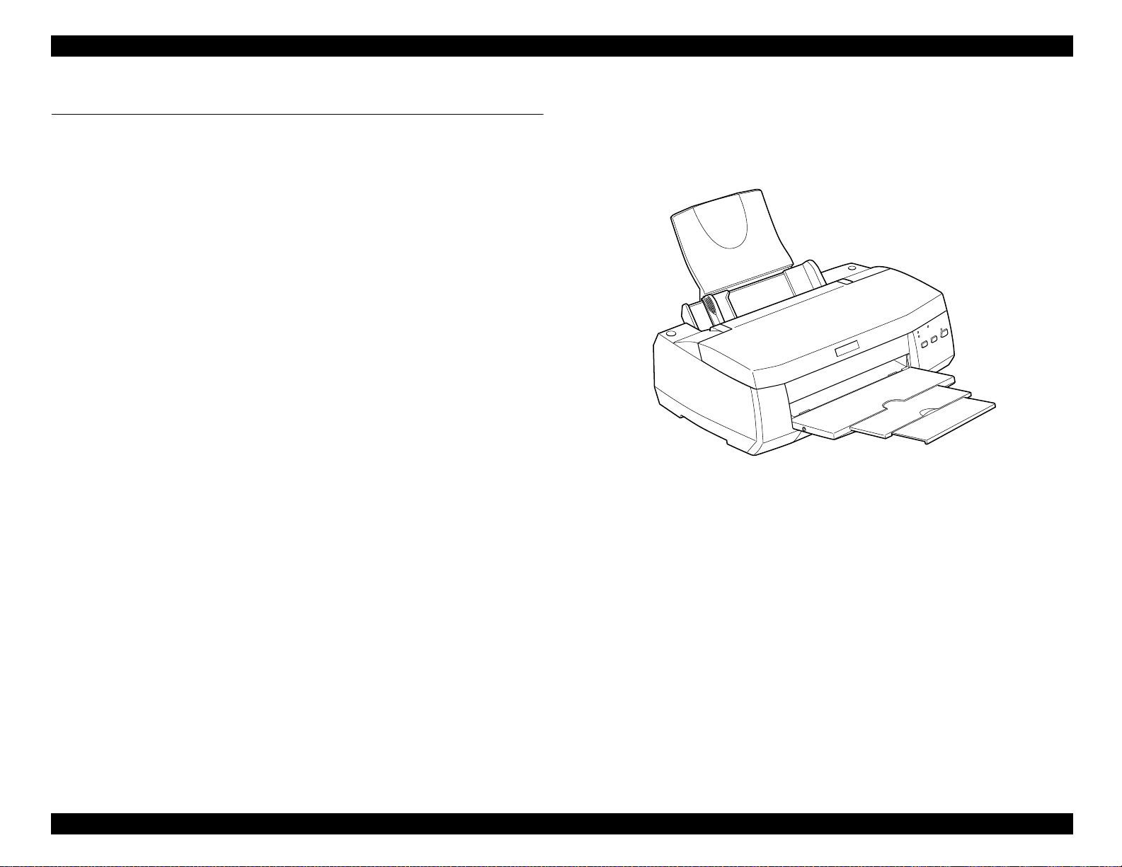
The Stylus COLOR 980 is the latest in EPSON’s advanced lines of ink
jet printers and offering the following features.
High color print quality:
- 2880 (H) x1440 (V) dpi printing
- Printing with 4 color inks (YMCK)
- Traditional and New Microweave
- Improvement in color rendering using variable dot
Built-in auto sheet feeder:
2
- Holds 100 cut-sheets (64 g/m
- Holds 10 envelopes
- Holds 30 transparency fIlms
Built-in 3 I/F
- Bi-directional parallel I/F (lEEE-1284 level 1 device)
- USB
- Optional Type-B level 2 I/F card slot
)
Figure 1-1. Stylus Color 980
4 scaleable fonts, 5 LQ fonts
13 character tables (Standard version)
37 character tables (NLSP version)
Duplex printing mode
Product Description Features 5
Page 10
EPSON Stylus Color 980 Revision A
1.2 Specifications
Print direction: Bi-direction with logic seeking
Print speed and Printable columns
1.2.1 Printing Specifications
Print method: On demand ink jet
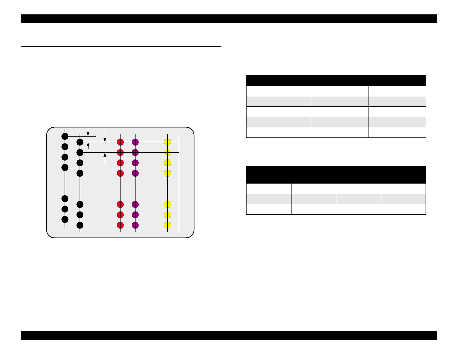
Nozzle configuration: Monochrome=192 nozzles (96 x 2 staggered)
Color=96 nozzles x 3 (Cyan, Magenta,
Yellow)
(See Figure 1-2 for the nozzle configuration.)
#96
#96
#95
#95
#94
#94
#93
#93
#3
#3
#2
#2
#1
#1
R ow A (B lack 1)
R ow B (B lack 2)
Figure 1-2. Nozzle configuration
360 dpi
180 dpi
#96
#95
#94
#93
#3
#2
#1
R ow C (M agenta)
Row D (Cyan)
#96
#95
#94
#93
#3
#2
#1
Row E (Yellow)
Table 1-1.
Print Speed and Printable Columns for Character Mode
Character pitch Printable columns LQ speed
10 CPI (Pica) 80 285 CPS
12 CPI (Elite) 96 342 CPS
15 CPI 120 428 CPS
17 CPI (Pica condensed) 137 487 CPS
20 CPI (EIite condensed) 160 570 CPS
Table 1-2.
Print Speed and Printable columns for Raster Graphics Mode
Horizontal
resolution
180 dpi 8.26 inch 1488 28.5 IPS
360 dpi 8.26 inch 2976 28.5 IPS
720 dpi 8.26 inch 5952 20 IPS
Control code: ESC/P2 and expanded raster graphics code
Printab le area Available dot CRS
EPSON Remote command
IBM X24E emulation
Product Description Specifications 6
Page 11

EPSON Stylus Color 980 Revision A
Character tables: Legal and 14 international character sets
Standard version: (13 character tables)
Italic table PC 860 (Portuguese)
PC 850 (Multilingual) PC 437(US, Standard Europe)
PC 861 (Icelandic) PC 863(Canadian-French)
PC 865(Nordic) Abicomp
BRASCII Roman 8
ISO Latin 1 PC 858
ISO 8859-15
NLSP version: (36 character tables)
Italic table PC437 PC437 Greek
PC850 PC852 PC853
PC855 PC857 PC860
PC861 PC865 PC866
PC869 MAZOWIA Code MJK
ISO 8859-7 lSO Latin 1T Bulgaria
PC774 Estonia ISO 8859-2
PC866 LAT PC866 UKR PC AR864
PC APTEC PC708 PC720
Hebrew7* Hebrew8* PC862*
Abicomp BRASCII Roman 8
ISO Latin 1 PC 858 lSO 8859-15
Typeface
Bit map LQ font:
EPSON Roman 10 CPI, 12 CPI, 15CPI, Proportional
EPSON Sans Serif 10 CPI, 12 CPI, 15CPI, Proportional
EPSON Courier 10 CPI, 12 CPI, 15CPI
EPSON Prestige 10 CPI, 12 CPI, 15CPI
EPSON Script 10 CPI, 12 CPI, 15CPI
Scaleable font
EPSON Roman 10.5 pt., 8 pt., - 32 pt. (every 2 pt.)
EPSON Sans Serif 10.5 pt., 8 pt., - 32 pt. (every 2 pt.)
EPSON Roman T 10.5 pt., 8 pt., - 32 pt. (every 2 pt.)
EPSON Sans Serif H 10.5 pt., 8 pt., - 32 pt. (every 2 pt.)
* Each Typeface has 4 variation s as the following example of
EPSON Roman.
EPSON Roman normal
EPSON Roman bold
EPSON Roman italic
EPSON Roman bold italic
See Table 1-3 which lists the character tables and available
typefaces.
Feeding method: Friction feed with ASF
* These character tables can not be selected in the Default setting
mode.
Product Description Specifications 7
Line spacing: 1/6 inch, 1/8 inch or programable at 1/360
inch
Paper path: Cut-sheet ASF (Top entry, Front out)
Feed speed: 192/360 inch feed = 116 ms
Continuous feed = 176.3 mm/second
(6.94 inch/second)
Input data buffer: 256 KB
Page 12

EPSON Stylus Color 980 Revision A
Table 1-3. Character Tables and Available Typefaces
Character Tables Bit map font Scaleable font
Italic table
PC 860 (Portuguese)
PC 861 (Icelandic)
PC 865 (Nordic)
Abicomp
lSO Latin1
Standard version
ISO 8859-15
Italic table
PC 850 (Multilingual)
PC 861 (Icelandic)
Abicomp
lSOLatin1
ISO 8859-15
PC437Greek
PC 853 (Turkish)
PC 857 (Turkish)
PC 869 (Greek)
Code MJK (CSFR)
lSO Latin 1T (Turkish)
NLSP version
PC 774
1SO 8859-2 (lSO Latin 2)
PC 866 UKR
PC APTEC (Arabic)
PC 720 (Arabic)
PC 437 (US Standard Europe)
PC 850 (Multilingual)
PC 863 (Canadian-French)
BRASCII
Roman 8
PC 858
PC 437(US Standard Europe)
PC 860(Portuguese)
PC 865(Nordic)
BRASCIl
Roman8
PC 858
PC 852 (East Europe)
PC 855 (Cyrillic)
PC 866 (Russian)
MAZOWIA (Poland)
lSO 8859-7 (Latin/Greek)
Bulgaria (Bulgarian)
Estonia
PC 866 LAT
PC 708 (Arabic)
PC AR864 (Arabic)
EPSON Roman
EPSON Sans Serif
EPSON Courier
EPSON Prestige
EPSON Script
EPSON Roman
EPSON Sans Serif
EPSON Courier
EPSON Prestige
EPSON Script
EPSON Roman
EPSON Sans Serif
EPSON Roman
EPSON Sans Serif
EPSON Roman T
EPSON Sans Serif H
EPSON Roman
EPSON Sans Serif
Not supported
Hebrew7*
Hebrew 8*
PC862 (Hebrew)*
EPSON Roman
EPSON Courier
Not supported
* Not mentioned in the User’s Guide. These character tables can not select in the default setting
mode.
Product Description Specifications 8
Page 13
EPSON Stylus Color 980 Revision A
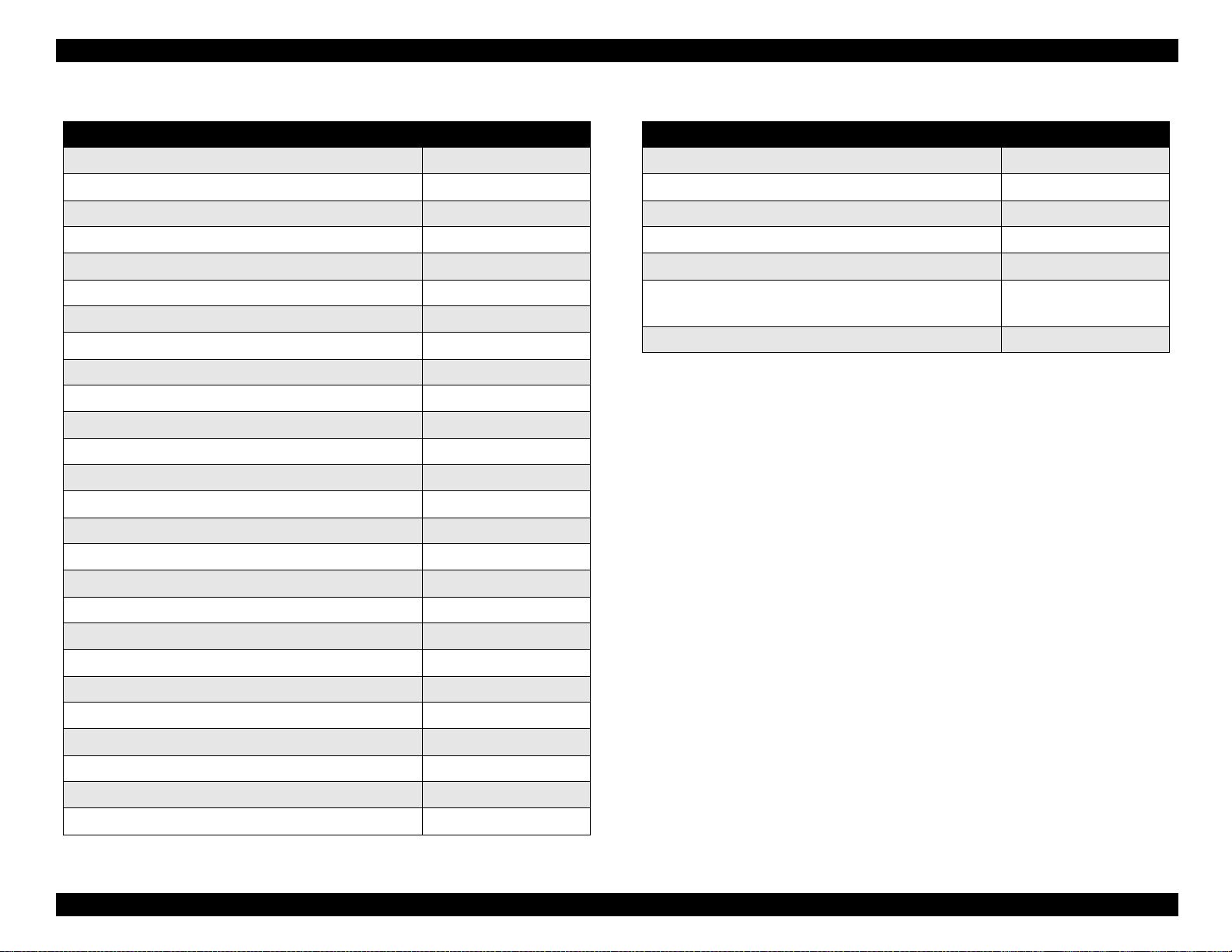
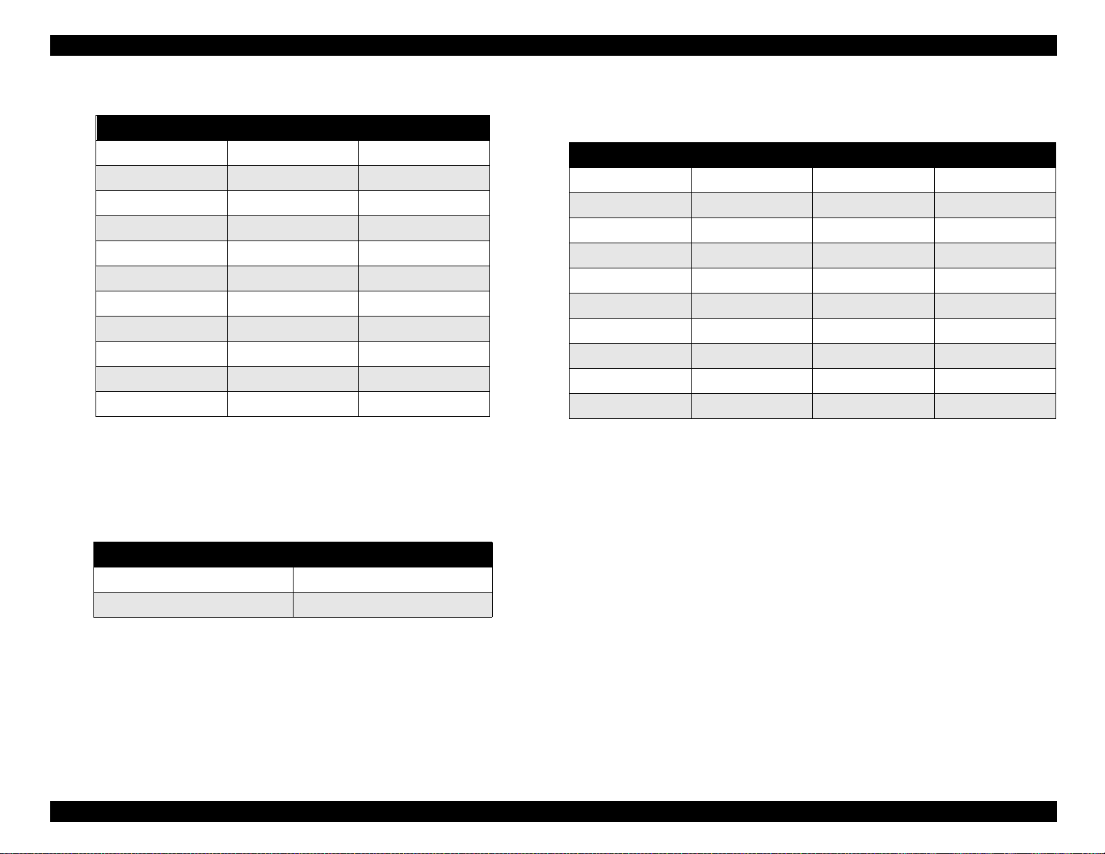
1.2.2 Options and Consumable Products
∗
NOTE:The asterisk (
number, which varies by country.
NOTE:The availability of special media varies by country.
Table 1-4. Options Available for Stylus Color 980
Type B Multi-protocol Ethernet Interface Card C82362
Type B 100BASE-TX Multi-protocol Ethernet
Interface Card
Type B IEEE1394 Interface Card C82372
Table 1-5. Ink Cartridge Available for Stylus Color 980
) is a substitute for the last digit of the product
Items Codes
∗
/C82364
C82363
C82384
∗
∗
∗
Items Codes
Black Ink Cartridge T003
∗
Color Ink Cartridge T005
See Table 1-6 and 1-7 which show the EPSON Special Media.
Product Description Specifications 9
Page 14
EPSON Stylus Color 980 Revision A
Table 1-6. EPSON Special Media Table 1-7. EPSON Special Media (continued)
Items Codes
Items Codes
EPSON 360 dpi Ink Jet Paper (A4) S041059 / S041025
EPSON 360 dpi Ink Jet Paper (Letter) S041060 / S041028
EPSON Photo Quality Ink Jet Paper (A4) S041061 / S041026
EPSON Photo Quality Ink Jet Paper (Letter) S041062 / S041029
EPSON Photo Quality Ink Jet Paper (Legal) S041067 / S041048
EPSON Photo Quality Ink Jet Card (A6) S041054
EPSON Photo Quality Ink Jet Card (5 x 8”) S041121
EPSON Photo Quality Ink Jet Card (8 x 10”) S041122
EPSON Photo Quality Self Adhesive Sheet (A4) S041106
EPSON Ink Jet Note Card (A6) (with envelopes) S041147
EPSON Ink Jet Greeting Cards (5 x 8”) (with envelopes) S041148
EPSON Ink Jet Greeting Cards (8 x 10”) (with envelopes) S041149
EPSON Photo Quality Glossy Film (A4) S041071
EPSON Photo Quality Glossy Film (Letter) S041072
EPSON Photo Quality Glossy Film (A6) S041107
EPSON Ink Jet Transparencies (A4) S041063
EPSON Ink Jet Transparencies (Letter) S041064
EPSON Photo Paper (A4) S041140
EPSON Photo Paper (100 x 150mm) S041255
EPSON Photo Paper (200 x 300mm) S041254
EPSON Premium Ink Jet Plain Paper (A4) S041214
EPSON Premium Glossy Photo Paper (A4) S041287 / S041297
EPSON Premium Glossy Photo Paper (Letter) SO41286
EPSON Matte Paper-Heavy weight (A4)
EPSON Matte Paper-Heavy weight (Letter) S041257
S041256 / S041258
S041259
EPSON Photo Paper (Letter) S041141
EPSON Photo Paper (4 x 6”) S041134
EPSON Photo Paper Cards (A4) S041177
EPSON Photo Stickers 16 (A6) S041144
EPSON Photo Stickers 4 (A6) S041176
EPSON Panoramic Photo Paper (210 x 594 mm) S041145
EPSON Iron-On Cool Peel Transfer Paper (A4) S041154
EPSON Iron-On Cool Peel Transfer Paper (Letter) S041153 / S041155
Product Description Specifications 10
Page 15

EPSON Stylus Color 980 Revision A
1.2.3 Paper Specifications
This section describes paper specifications including paper handling
and printable area.
Paper Handling: Do not feed paper in reverse more than 9.5 mm
(0.38”).
1.2.3.1 Cut Sheet
Size:
A4: [Width 210 mm (8.3”) x Length 297 mm (11.7”)]
A5: [Width 148 mm (5.8”) x Length 210 mm (8.3”)]
Letter: [Width 216 mm (8.5”) x Length 279 mm (11.0”)]
B5: [Width 182 mm (7.2”) x Length 257 mm (10.1”)]
Legal: [Width 216 mm (8.5”) x Length 356 mm (14.0”)]
Half Letter: [Width 139.7 mm (5.5”) x Length 215.9 mm (8.5”)]
Executive: [Width 184.2 mm (7.25”) x Length 266.7mm(10.5”)]
Thickness: 0.08 mm (0.003”) - 0.11 mm (0.004”)
Weight: 64g/m
Paper Types: Bond paper, Plain paper, EPSON special media
2
(17Ib.) - 90g/m2 (24Ib.)
1.2.3.3 Envelope
Size:
No.10: [Width 241 mm (9 1/2”) x Length 104.8 mm (4 1/8”)]
DL: [Width 220 mm (8.7”) x Length 110 mm (4.3”)]
C6: [Width 162 mm (6.4”) x Length 114 mm (4.5”)]
5 x 8”: [Width 220 mm (8.7”) x Length 132 mm (5.2”)]
Thickness: 0.16 mm (0.006”) - 0.52 mm (0.02”)
Weight: 45g/m
Paper Types: Bond paper, Plain paper, Air mail
NOTES:
1. Print on envelope at normal temperatures only.
2. Place the longer side of the envelope horizontal.
2
(12Ib.) - 75g/m2 (20Ib.)
1.2.3.4 Index Card
Size:
A6 Index card: [Width 105 mm (4.1”) x Length 148 mm (5.8”)]
5 x 8” Index card: [Width 127 mm (5.0”) x Length 203 mm (8.0”)]
10 x 8” Index card:[Width 127 mm (5.0”) x Length 203 mm (8.0”)]
Thickness
1.2.3.2 Transparency, Glossy Fi lm
Size
A4: [Width 210 mm (8.3”) x Length 297 mm (11.7”)]
Letter: [Width 216 mm (8.5”) x Length 279 mm (11.0”)]
A6: [Width 105 mm (4.1”) x Length 148 mm (5.8”)]
Thickness: 0.075 mm (0.003”) - 0.085 mm (0.0033”)
Paper Types: EPSON special media
NOTE:Print on transparency at normal temperatures only.
Product Description Specifications 11
Paper Types: EPSON special media
1.2.3.5 Self Adhesive Sheets
Size
A4: [Width 210 mm (8.3”) x Length 297 mm (11.7”)]
Paper Types: EPSON special media
:
Less than 0.23 mm (0.0091”)
Page 16

EPSON Stylus Color 980 Revision A
1.2.3.6 Photo Paper
Size:
A4: [Width 210 mm (8.3”) x Length 297 mm (11.7”)]
Letter: [Width 216 mm (8.5”) x Length 279 mm (11.0”)]
4 x 6”: [Width 102 mm (4”) x Length 152 mm (6”)]
Panoramic: [Width 210 mm (8.3”) x Length 594 mm (23.4”)]
Paper Types: EPSON special media
1.2.3.7 Photo Stickers
Size:
A6 with 4 or 16 frames:
[Width 105 mm (4.1”) x Length 148 mm (5.8”)]
Paper Types: EPSON special media
Product Description Specifications 12
Page 17
EPSON Stylus Color 980 Revision A
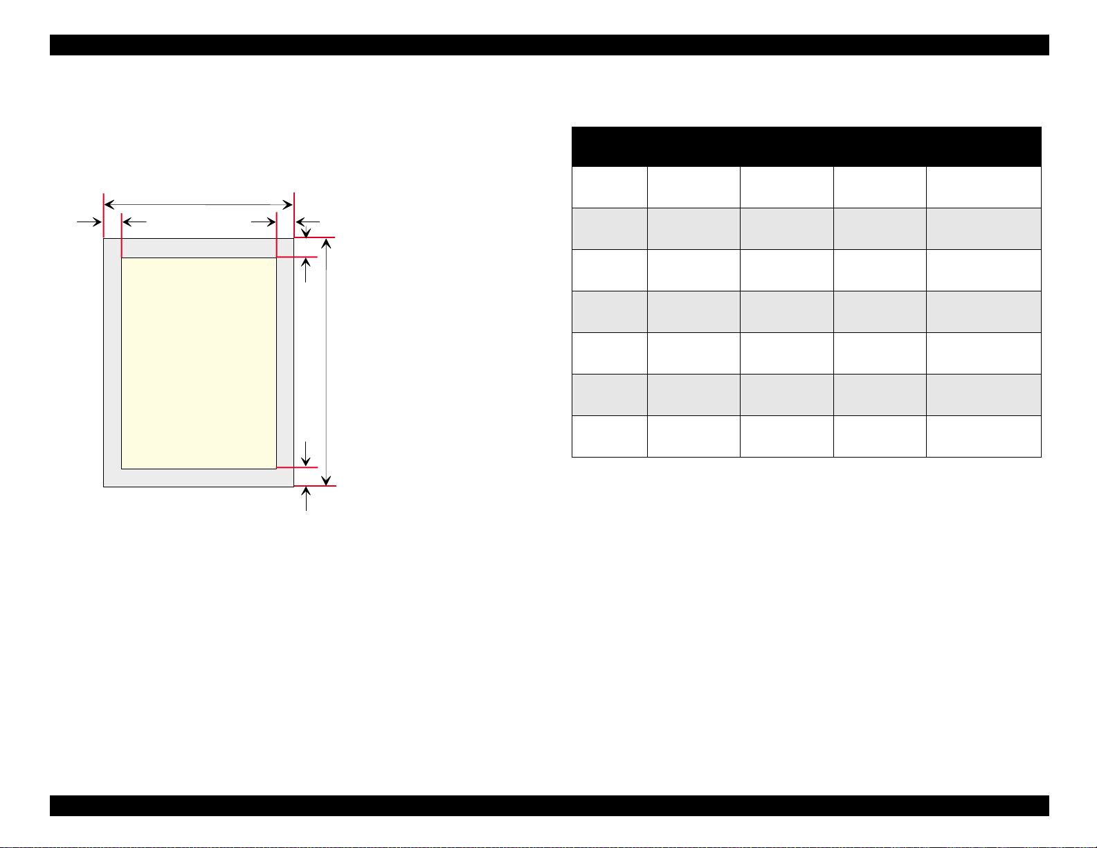
1.2.4 Printable Area
Cut Sheet
See Figure 1-3 and Table 1-8 for the printable area for cut sheets.
PW
LM
Printable area
Figure 1-3. Printable Area for Cut Sheets
TM
BM
RM
PL
L M : L e ft M a rg in e
R M : R ight M argine
TM : Top M argine
B M : B o tto m M a rg in e
PW : P aper W idth
PL: P aper Length
Table 1-8.
Minimum margin for Raster Graphics Mode / Character Mode
Paper
Size
A4 3 mm (0.12”) 3 mm (0.12”) 3 mm (0.12”)
A5 3 mm (0.12”) 3 mm (0.12”) 3 mm (0.12”)
Letter 3 mm (0.12”)
B5 3 mm (0.12”) 3 mm (0.12”) 3 mm (0.12”)
Legal 3 mm (0.12”)
Half Letter 3 mm (0.12”) 3 mm (0.12”) 3 mm (0.12”)
Executive 3 mm (0.12”) 3 mm (0.12”) 3 mm (0.12”)
*1: For Raster Graphics mode
*2: For Character mode
*3: The minimum bottom margin is reduced to 3 mm when paper dimension is defined
by using the command. Otherwise, the minimum bottom margin remains 14 mm.
Note the extra printing area with the bottom margin of 3 mm is not a guaranteed
area.
Left Margin
(Minimum)
Right Margin
(Minimum)
3 mm (0.12”)*
9 mm (0.35”)*
3 mm (0.12”)*
9 mm (0.35”)*
Top Margin
(Minimum)
1
3 mm (0.12”)
2
1
3 mm (0.12”)
2
Bottom Margin
(Minimum)
14 mm (0.54”)
3 mm (0.12”) *
14 mm (0.54”)
3 mm (0.12”) *
14 mm (0.54”)
3 mm (0.12”) *
14 mm (0.54”)
3 mm (0.12”) *
14 mm (0.54”)
3 mm (0.12”) *
14 mm (0.54”)
3 mm (0.12”) *
14 mm (0.54”)
3 mm (0.12”) *
3
3
3
3
3
3
3
Product Description Specifications 13
Page 18
EPSON Stylus Color 980 Revision A
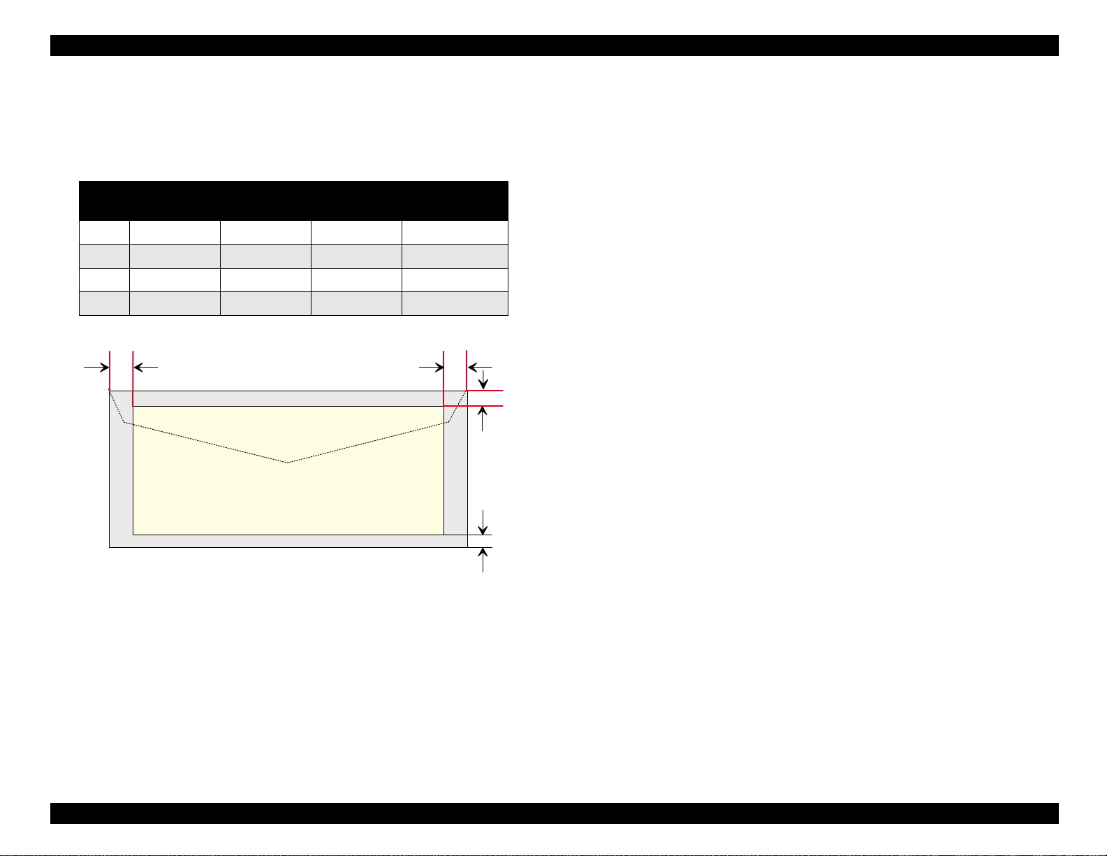
Envelope See Table 1-9 and Figure 1-4 which show the minimum
margin and printable area for envelopes, respectively.
Table 1-9. Minimum Margin for Envelopes
Paper
Size
#10 3 mm (0.12”) 28 mm (1.10”) 3 mm (0.12”) 14 mm (0.54”)
DL 3 mm (0.12”) 7 mm (0.28”) 3 mm (0.12”) 14 mm (0.54”)
C6 3 mm (0.12”) 3 mm (0.12”) 3 mm (0.12”) 14 mm (0.54”)
5 x 8 3 mm (0.12”) 7 mm (0.28”) 3 mm (0.12”) 14 mm (0.54”)
Left Margin
(Minimum)
Right Margin
(Minimum)
Top Margin
(Minimum)
Bottom Margin
(Minimum)
RMLM
TM
Printable
A re a
BM
Figure 1-4. Printable Area for Envelopes
Product Description Specifications 14
Page 19
EPSON Stylus Color 980 Revision A
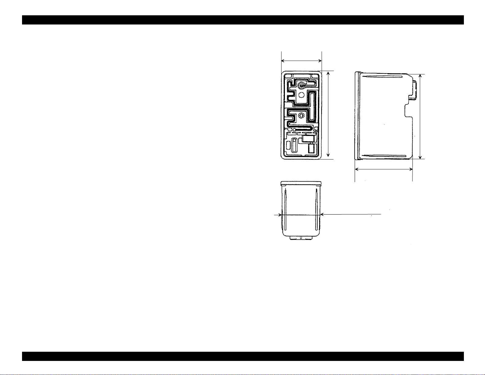
1.2.5 Ink Cartridge Specifications
28.9 m m
1.2.5.1 Black Ink Cartridge
Type: Exclusive ink cartridge
Color: Black
Print Capacity: 1200 pages / A4 (ISO/IEC 10561 Letter
Pattern at 360 dpi)
Ink life: 2 years from indicated production date
Storage temperature:
Storage: -20°C ~ 40°C(within a month at 40 °C)
Packing storage: -30°C ~ 40°C(within a month at 40 °C)
Transit: -30°C ~ 60°C(within 120 hours at 60°C and
within a month at 40°C)
67.4 m m
65.9 m m (R ib area)
Dimensions: 28.9 mm (W) x 67.4 mm (D) x 41.8 mm (H)
41.8 m m
27.4 m m (R ib area)
Figure 1-5. Black Ink Cartridge Appearance
Product Description Specifications 15
Page 20

EPSON Stylus Color 980 Revision A
1.2.5.2 Color Ink Cartridge
Type: Exclusive ink cartridge
Color: Magenta, Cyan, Yellow
Print Capacity: 530 pages / A4 (at 360 dpi, 5% duty each
color)
Ink life: 2 years from indicated production date
Storage temperature:
Storage: -20°C ~ 40°C(within a month at 40 °C)
Packing storage: -30°C ~ 40°C (within a month at 40 °C)
Transit: -30°C ~ 60°C (within 120 hours at 60°C and
within a month at 40°C)
Dimensions: 54.0 mm (W) x 67.4 mm (D) x 41.8 mm (H)
NOTES
1. Do not refill the cartridge. It is a consumable item.
2. Do not used the ink cartridge whose ink life has expired.
°
Ink will be frozen below -4
3.
C. To use ink that is frozen, let it defrost
for at least 3 hours at room temperature.
54 m m
67.4 m m
65.9 m m (R ib area)
41.8 m m
52.5 m m (R ib area)
Figure 1-6. Color Ink Cartridge
Product Description Specifications 16
Page 21

EPSON Stylus Color 980 Revision A
Humidity
(% RH)
80%
55%
20%
10 27
35
50
( C )
80
95
( F )
G uaranteed
A re a
1.2.6 Electrical Specifications
[120V version]
Rated voltage: AC120V
Input voltage range: AC99 ∼132V
Rated frequency range: 50 ∼ 60 Hz
Input frequency range: 49.5 ∼ 60.5 Hz
Rated current: 0.7A (Maximum 1.0A)
Power consumption: Approx.30W (ISO/IEC 10561 Letter pattern)
Energy Star compliant
Insulation Resistance: 10 M ohms min.
(between AC line and chassis, DC 500 V)
Dielectric strength: AC1000 V rms. 1 minute or AC1200 Vrms.
1 second (between AC line and chassis)
[220∼240V version]
Rated voltage: AC220V ∼ 240V
1.2.7 Environmental Condition
Temperature: Operating = 10 to 35 °C (See Figure 1-7.)
Non-operating = -20 to 60 °C *1
1 month at 40 °C
120 hours at 60 °C
Humidity: Operating = 20% ~ 80% RH *1
(See Figure 1-7.)
Non-operating = 5% ~ 85% RH *1 *2
Input voltage range: AC198 ∼ 264V
Rated frequency range: 50 ∼ 60Hz
Input frequency range: 49.5 ∼ 60.5Hz
Rated current: 0.4A (Maximum 0.5A)
Power consumption: Approx.30W (ISO/IEC 10561 Letter pattern)
Energy Star compliant
Insulation Resistance: 10M ohms min.
Product Description Specifications 17
Dielectric strength: AC1500 V rms.
(between AC line and chassis, DC500V)
1 minute (between AC line and chassis)
Resistance to shock: Operating = 1G, within 1 ms
Resistance to vibration: Operating = 0.15G (Operating)
*1: With a shipment container
*2: Without condensation
Figure 1-7. Temperature / Humidity of Range
Non-operating = 2G, within 2 ms *1
Non-operating = 0.50G *1
Page 22

EPSON Stylus Color 980 Revision A
1.2.8 Reliability
Total print volume: 75,000 pages (A4, Letter)
Printhead life: 4000 million dots/nozzle
1.2.9 Safety Approvals
[120V version]
Safety standard: UL1950
CSA22.2 No.950
EMI: FCC part 15 subpart B class B
CSA C108.8 class B
[220∼240V version]
Safety standard: EN 60950 (VDE)
EMI: EN55022 (CISPR Pub.22) class B
AS/NZS 3548 class B
1.2.10 Acoustic Noise
1.2.11 CE Marking (220 ∼ 240 V version)
Low Voltage Directive 73/23/EEC: EN60950
EMC Directive 89/336/EEC: EN55022 Class B
EN61000-3-2
EN61000-3-3
EN50082-1
IEC801-2
IEC801-3
IEC801-4
1.2.12 Physical Specifications
Weight: 8.4 Kg
Dimensions: 467 mm (W) x 296 mm (D) x 325 mm (H)
Level: Approximately 47 dB (A) (According to ISO
7779)
Product Description Specifications 18
Page 23
EPSON Stylus Color 980 Revision A
-
1.3 Interface
The EPSON Stylus Color 980 is equipped with USB, Bi-directional 8-bit
parallel interface and a card slot for an optional Type-B interface.
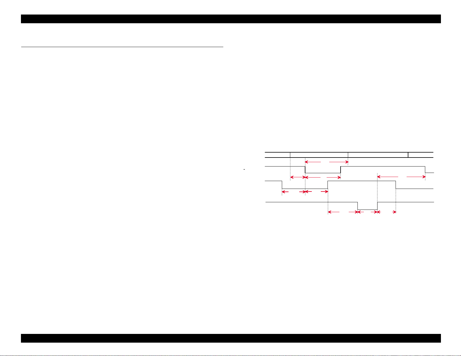
1.3.1 Parallel Interface (Forward Channel)
Transmission mode: 8 bit parallel, IEEE-1284 compatibility mode
Synchronization: By /STROBE pulse
Handshaking: BY BUSY and /ACKLG signal
Signal level: TTL compatible level
Adaptable connector: 57-30360 (amphenol) or equivalent
The BUSY signal is set high before setting either/ERROR low or PE
high, and held high until all these signals return to their inactive state.
The BUSY signal is HIGH:
During data entry (see Data transmission timing)
When the input data buffer is full
During/INIT signal is at LOW level or during hardware
initialization.
The ERROR signal is LOW when one of the following error has
occurred:
Printer hardware error (fatal error)
Paper Out error
Paper Jam error
Ink Out error
The PE signal is at a high level during Paper Out error.
See Figure 1-8 and Table 1-10 which show the data transmission
timing.
DATA
STROBE
BUSY
-ACKNLG
tsetup
tready
data byte n
thold
ts tb
tbusy
treply ta c k
tnbusy
data byte n+1
tnext
Figure 1-8. Data Transmission Timing
During a printer error condition (See /ERROR signal).
When the parallel interface is not selected.
Product Description Interface 19
Page 24
EPSON Stylus Color 980 Revision A
Table 1-10. Data Transmission Timing
Parameter Minimum Maximum
tsetup 500ns ---
thold 500ns ---
tstb 500ns ---
tready 0 ---
tbusy --- 500ns
tt-out* --- 120ns
tt-in** --- 200ns
treply 0 ---
tack 500ns 10us
tnbusy 0 ---
tnext 0 ---
NOTE:tt-out shows the rise and fall time of every output signal.
tt-in shows the rise and fall time of every input signal.
Typical time of tack is shown in Table 1-11.
Table 1-11. Typical Time of Tack
Table 1-12. Signal level for TTL Compatible
(IEEE-1284 level 1 device)
Parameters Minimum Maximum Condition
VOH* --- 5.5V
VOL* -0.5V ---
IOH* --- 0.32mA VOH = 2.4V
IOL --- 12mA VOL = 0.4V
CO --- 50pF
VIH --- 2.0V
VIL 0.8V ---
IIH --- 0.32mA VIH = 2.0V
IIL --- 12mA VIL = 0.8V
CI --- 50pF
* A LOW logic level on the Logic H signal is as follows:
2.0 V or less when the printer is turned off.
3.0 V or more when the printer is turned on.
The receiver provides an impedance equivalent to 7.5 K
ground.
Ω
to
Parallel Interface Mode Typical Time of Tack
High speed 1 us
Normal speed 3 us
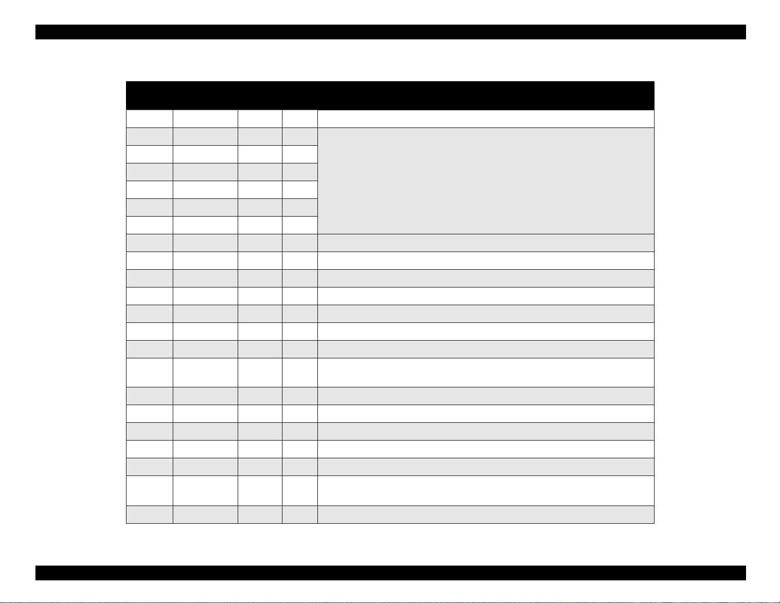
See Table 1-13 which shows the connector pin assignment and signals
for the forward channel of the parallel interface.
Product Description Interface 20
Page 25
EPSON Stylus Color 980 Revision A
Table 1-13. Parallel I/F Forward Channel
Pin No. Signal Name
1 /STROBE 19 I The strobe pulse. Read-in of data is performed at the falling edge of this pulse.
2 DATA0 20 I
3DATA1 21
4 DATA2 22
5DATA3 23
6 DATA4 24
7DATA5 25
8 DATA6 26
9DATA7 27
10 /ACKNLG 28 O This signal is a negative pulse indicating that the printer can again accept data.
11 BUSY 29 O A high signal indicates that the printer cannot receive data.
12 PE 28 O A high signal indicates paper-out error.
13 SLCT 28 O Always at high level when the printer is powered on.
14 /AFXT 30 I Not used.
31 /INIT 30 I
Return
GND Pin
In/Out Functional Description
The DATA0 through DATA7 signals represent data bits 0 to 7, respectively. Each
signal is at high level when data is logical 1 and low level when data is logical 0.
The falling edge of a negative pulse or a low signal on this line causes the printer to
initialize. Minimum 50 us pulse is necessary.
32 /ERROR 29 O A low signal indicates printer error condition.
36 /SLIN 30 I Not used.
18 Logic H ---- O Pulled up to +5V via 3.9K ohm resistor.
35 +5V ---- O Pulled up to +5V via 3.9K ohm resistor.
17 Chassis GND ---- --- Chassis GND.
16,33,
19-30
15,34 NC ---- --- Not connected.
*: In and Out refers to the direction of the signal as viewed from the printer.
GND ---- --- Signal GND.
Product Description Interface 21
Page 26

EPSON Stylus Color 980 Revision A
1.3.2 Parallel Interface (Reverse Channel)
Transmission mode: IEEE-1284 nibble mode
Adaptable connector: See the forward channel.
Synchronization: Refer to the IEEE-1284 specification
Handshaking: Refer to the IEEE-1284 specification
Data trans. timing: Refer to the IEEE-1284 specification
Signal level: IEEE-1284 level 1 device
(See forward channel.)
Extensibility request:
The printer responds affirmatively when the extensibility request
values are 00H or 04H,as follows;
00H:Request Nibble Mode Reverse Channel Transfer.
04H:Request device ID using Nibble Mode Rev Channel
Transfer.
Device ID:
The printer sends following device ID string upon request.
When IEEE1284.4 is disabled;
[00H] [5DH]
MFG:EPSON;
CMD:ESCPL2,PRPXL,BDC;
MDL:Stylus[SP]COLOR[SP]980;
CLS:PRINTER;
DES:EPSON[SP]Stylus[SP]COLOR[SP]980;
NOTES:
1. [00H] denotes a hexadecimal value of zero.
2. MDL value and DES value depend on the EEPROM setting.
3. CMD value depends on the IEEE1284.4 setting.
See Table 1-14 which shows pin assignment for reverse channel
When IEEE1284.4 is enabled;
[00H] [60H]
MFG:EPSON;
CMD:ESCPL2,PRPXL,BDC,D4;
MDL:Stylus[SP]COLOR[SP]980;
CLS:PRINTER;
DES:EPSON[SP]Stylus[SP]COLOR[SP]980;
Product Description Interface 22
Page 27
EPSON Stylus Color 980 Revision A
Table 1-14. Pin Assignment For Reverse Channel
Pin No. Signal Name
1 HostClk 19 I Host clock signal.
2-9 Data0-7 20-27 I
10 PrtClk 28 O Printer clock signal.
11 PtrBusy, Data Bit-3,7 29 O Printer busy signal and reverse channel transfer data bit 3 or 7.
Return GND
Pin
In/Out Functional Description
The DATA0 through DATA7 signals represent data bits 0 to7,
respectively. Each signal is at high level when data is logical 1 and
low level when data is logical 0. These signals are used to transfer
the 1284 extensibility request values to the printer.
12 AckData Req, DataBit-2,6 28 O
13 Xflag, DataBit-1,5 28 O X-flag signal and reverse channel transfer data bit 1 or 5.
14 HostBusy 30 I Host busy signal.
31 /INIT 30 I Not used.
32 /DataAvail, DataBit-0,4 29 O Data available signal and reverse channel transfer data bit 0 or 4.
36 1284-Active 30 I 1284 Active Signal
18 Logic-H ---- O Pulled up to +5V via 3.9K ohm resister.
35 +5V ---- O Pulled up to +5V via 3.3K ohm resister.
17 Chassis GND ---- --- Chassis GND.
16,33, 19-30 GND ---- --- Signal GND.
15,34 NC ---- --- Not connected.
* In/Out refers to the direction of signal flow from the printer’s point of view.
Acknowledge data request signal and reverse channel transfer
data bit 2 or 6.
Product Description Interface 23
Page 28
EPSON Stylus Color 980 Revision A
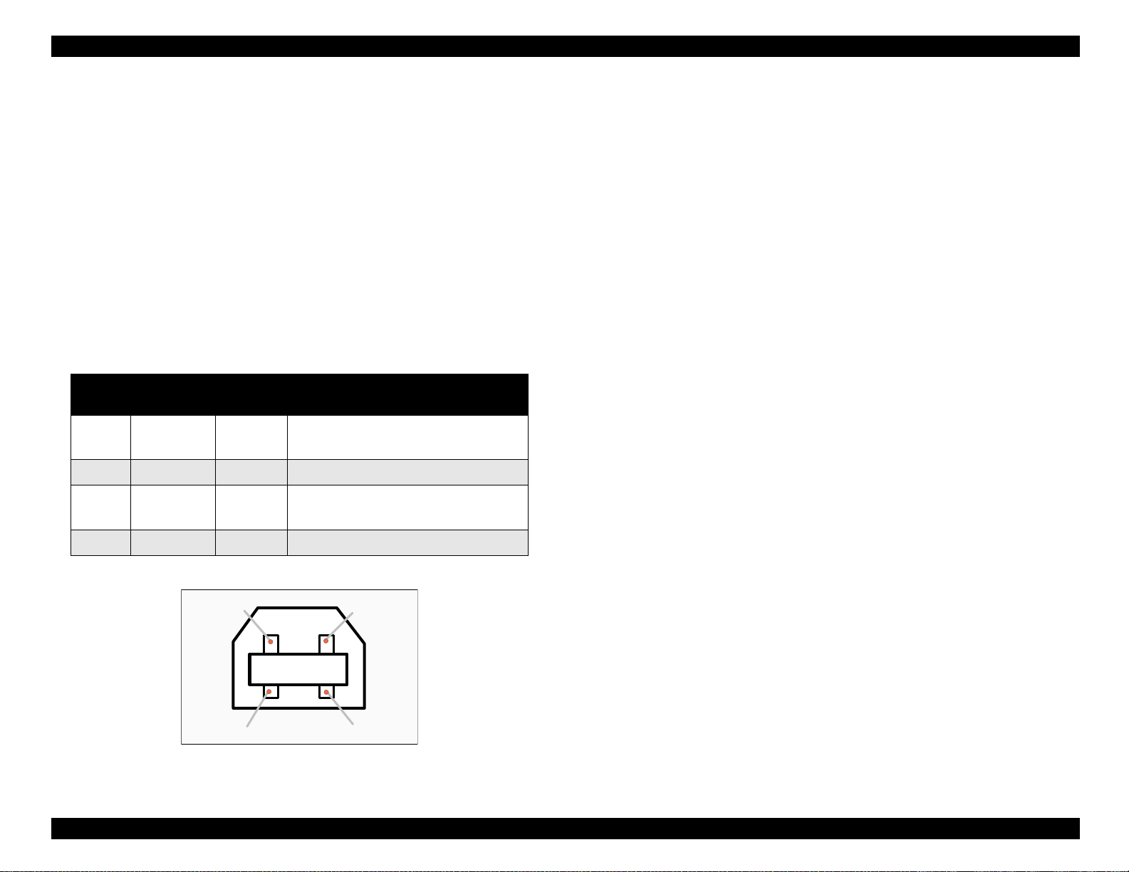
1.3.3 USB Interface
Standard: Based on the following:
Universal Serial Bus Specifications Rev. 1.0
Universal Serial Bus Device Class Definition
for Printing Device Version 1.0
Bit Rate: 12 M bps
Data Encoding: NRZI
Adaptable Connector:USB Series B
Recommended Cable Length:2 meters
Table 1-15. Pin Assignment and Signal of the USB I/F
Pin No.
1 Vcc ----
2 -Data Bi-D Data
3+DataBi-D
4 Ground ---- Cable Ground
Signal
Name
I/O Description
Cable power, Maxi. power consumption
is 100 mA
Data, pull up to +3.3 V via 1.5 K ohms
resistor
Pin #2
Pin #1
1.3.4 Optional interface
Type-B level 2 optional interfaces are available.
Reply message:
ESC/P2 is selected
Min-Type:MTP48p, PW80 cl 10 cpi, PRG (Wxxxxx)rev,
AP800ma, SPDO fast
Product-Name: Stylus COLOR 980
Emulation-Type: ESCPL2-00
Entity-Type: EPSONLQ2
X24E is selected
Main-Type:MTP48p, PW80cl10cpi, PRG(Wxxxxx)rev,
AP800ma, SPDO fast
Product-Name: Stylus COLOR 980
Emulation-Type: PRPXL24-00
Entity-Type: EPSONPRPXL24
Emergency command
0x00 :Get device ID
0x01 :Get all status
Sending BDC-ST through DBIN register
When State-Reply is set “ON” by ST from Type-B I/F, sending BDCST through DBIN register is started. When State-Reply is started,
“Start” and “End” of BDC-ST characters are announced by sending
the Main command 0Eh.
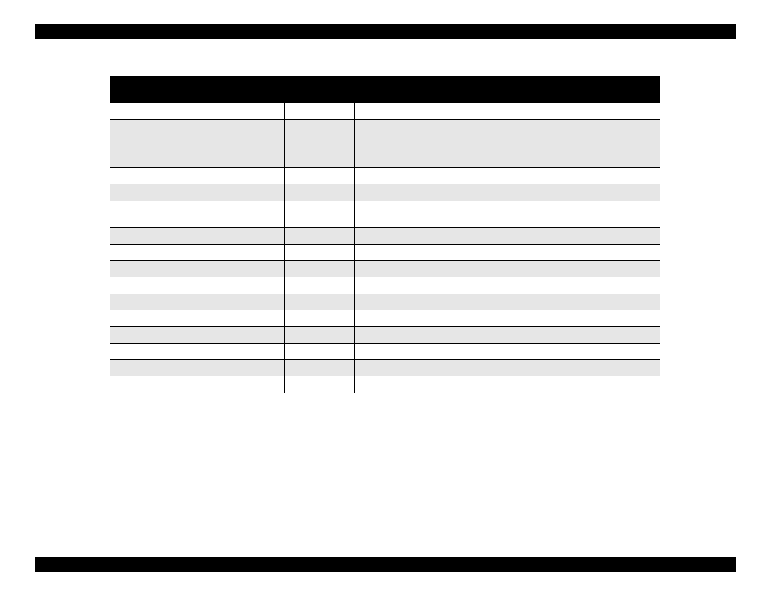
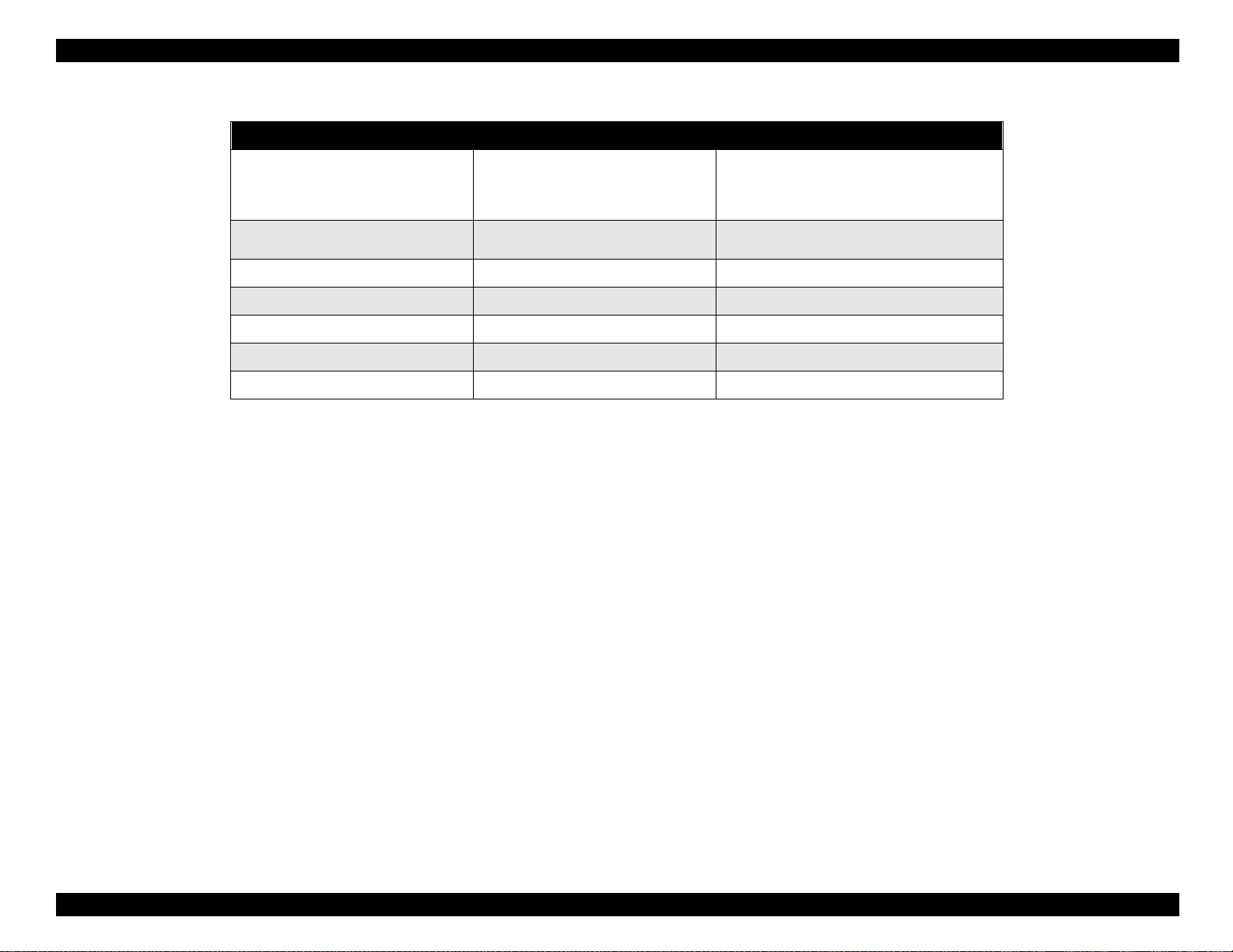
See Table 1-16 which shows Reply for option command.
See Table 1-17 which shows Supported main command and sending
timing
Pin #3
Pin #4
Figure 1-9. USB Pin Assignment
Product Description Interface 24
Page 29

EPSON Stylus Color 980 Revision A
Table 1-16. Reply for Option Command
Option command number Command name Reply-A Reply-B
00h No-operation None None
01h Start Hardware Reset Accept Execute OK
02h Start Software Reset Reject None
03h Send Main System Type Accept Execute OK
04h Send Name Data Reject None
05h Inquire Name Data Accept Execute OK
06h Send Product Name Accept Execute OK
07h Send Software Emulation Type Accept Execute OK
08h Complete Buffered Data Accept Check Condition
09h Stop Procedure Reject None
0Ah Return Buffered Data Reject None
0Bh Send Entity Type Accept Execute OK
0Ch Send Status Accept Execute OK
0Dh Quit Procedure Reject None
0Eh Inquire ASCII Message Reject None
0Fh Send ASCII Message Accept Execute OK
10h - 13h (Reserved) Unknown None
14h Inquire Emergency Message Accept Execute OK
15h Send Emergency Message Accept Execute OK
16h - 1Fh (Reserved) Unknown None
20h - FFh (Reserved) Unknown None
Product Description Interface 25
Page 30
EPSON Stylus Color 980 Revision A
Table 1-17. Supported main command and sending timing
Main command number Command name Sending timing
Start Software Reset
01h
02h
04h Send Name Data
Send Option Type
-INIT signal on the std. parallel I/F
Type-B I/F option command : 01h
Cold start
Deciding the level of Type-B I/F after
powered on
Type-B I/F option command : 05h
07h Inquire Software Emulation Name
0Eh Inquire ASCII Message
14h Inquire Emergency Reply
15h Send Emergency Message
Changing Software Emulation Type
Writing to DBIN register
Reply for Emergency command
Receive Emergency command
Product Description Interface 26
Page 31

EPSON Stylus Color 980 Revision A
1.3.5 Printer Language and Emulation
Printer language: ESC/P2
IBM X24E emulation
EPSON Remote
Interface state and interface selection
When the parallel interface is not selected, the interface goes
into the BUSY state.
NOTE:An interrupt signal, such as /I NIT, on the parallel interface is
not effective while that interface is not selected.
1.3.6 Prevention Hosts from Data Transfer time-out
Generally, hosts abandon data transfer to peripherals when a peripheral
is in the busy state for dozens of seconds continuously. To prevent
hosts from this kind of time-out, the printer receives data very slowly,
several bytes per minute, even if the printer is in busy state. This
slowdown is started when the rest of the input buffer becomes several
hundreds of bytes. Finally, the printer is in the busy state continuously
when the input buffer is full.
USB and IEEE1284.4 on the parallel interface do not require this function.
1.3.7 Auto Interface Selection
The EPSON Stylus Color 980 has three types of interfaces: USB,
parallel interface and optional Type-B interface. Each interface can be
selected manually in default setting mode or automatically.
Manual Selection:
One of three interfaces can be selected in default setting mode.
Automatic Selection:
The automatic interface selection is enabled by the default setting
mode. In this automatic interface selection mode, the printer is
initialized to the idle state scanning for which interface is to receive
data when it is powered on. The interface that receives data first is
selected. When the host stops data transfer and the printer is in the
stand-by state for a number of seconds, the printer returns to the
idle state. As long as the host sends data or the printer interface is
busy state, the selected interface is let as it is. The changes to other
interface are prohibited during duplex printing.
Product Description Interface 27
Page 32

EPSON Stylus Color 980 Revision A
1.3.7.1 IEEE 1284 .4 Protocol
The packet protocol described by IEEE1284.4 standard allows a device
to carry on multiple exchanges or conversations which contain data
and/or control information with another device at the same time across
a single point-to-point link. The protocol is not, however, a device
control language. It does provide basic transport-level flow control and
multiplexing services. The multiplexed logical channels are independent
of each other and blocking of one has no effect on the others. The
protocol operates over IEEE1284.
Automatic selection:
An initial state is compatible interface and starts IEEE1284.4
communication when magic strings (1284.4 synchronous
commands) are received.
ON:
IEEE1284.4 is enabled as initial state. Data sent before the magic
string (1284.4 synchronous commands) is discarded.
OFF:
IEEE1284.4 is disabled and IEEE1284.4 synchronous commands
are ignored. Compatible interface is the initial state.
Product Description Interface 28
Page 33

EPSON Stylus Color 980 Revision A
n
1.4 Control Panel Operation
The control panel of the EPSON Stylus Color 980 is composed of the 2
non-lock type push-buttons, 1 lock-type push-button, and 4 LEDs, as
shown below:
Paper O ut LED
In k O u t
(Black) LED
In k O u t
(Color) LED
C leaning
B u tto n
Power LED
Power Button
Load/E ject B utto
1.4.1 Indicators (LEDs)
1. Power
Lights when the operate switch is “ON”, and AC power is supplied.
2. Paper out
Lights during the paper-out condition, and blinks during the paperjam condition.
3. Ink Out (Black)
Lights during no Black ink condition, and blinks during the Black
ink low condition.
4. Ink Out (Color)
Lights during no Color ink condition, and blinks during the Color ink
low condition.
Figure 1-10. Control Panel
Product Description Control Panel Operation 29
Page 34

EPSON Stylus Color 980 Revision A
1.4.2 Panel Functions
Panel function: Refer to Table 1-18.
Table 1-18. Panel Functions
Button Function
• Loads or ejects paper.
Load/Eject
(within 2 seconds) *1
Load/Eject
(for 2 seconds) *1
Cleaning
(for 2 seconds) *1
Cleaning
(within 2 seconds) *1
*1: 3 seconds is specified in the Users Gu ide.
*2: This operation is not effective in printing status.
Panel function with power on:Refer to Table 1-19.
• When the carriage is in the I/C replacement position,
pressing this button returns the carriage to the capping
position.
• In the condition of “Double Feed Error” returning from
error condition printing is restarted
• Starts the I/C replacement sequence. *2
• Move the carriage to the I/C replacement position.
• Starts the printhead cleaning sequence.
• Starts the I/C replacement sequence when the printer
is in one of the following conditions:
“Ink Low”, “Ink Out”, No Ink Cartridge” *2
• When the carriage is in the I/C replacement position,
returns the carriage to the capping position.
1.4.2.1 Printer Setting Mode
While turning the printer on, press the Cleaning button, and the Paper
Out LED starts blinking. This operation must be followed by pressing
the specified button while the Paper Out LED is still blinking to enter the
Default setting mode or Printhead alignment mode, as described in
Table 1-20.
Table 1-20. Printer Setting Mode
Button Function / Operation
While the Paper Out LED is blinking, pressing
Cleaning or no button
Load/Eject
(Press it within 10 seconds.)
Load/Eject
(Hold it down for 10 seconds.)
*1: Leaving the Paper Out LED blinking wit hout pressi ng any butto n also gene rates
the Default setting mode.
*2: Not intended for users. This function is used only for troubleshooting.
the Cleaning or no button generates the
Default setting mode. *1
While the Paper Out LED is blinking, pressing
the Load/Eject button generates the Printhead
alignment mode.
Changes the default for the parallel I/F
communication protocol. *2
Table 1-19. Panel Function with Power On
Button Function
Load/Eject 1) Starts the status print. *1
Enters the printer setting mode. (The Paper Out LED starts
Cleaning
Load/Eject
+
Cleaning
*1: The status print includes firmware version, ink counter, and nozzle check
pattern.
blinking.) *2
Specified button must be then pressed while the LED is
blinking to activate each mode. (See Section 1.4.2.1.)
Enters the special setting mode. (Factory use only)
Specified button must be then pressed while the Paper Out
LED is blinking to activate each mode. (See Section
1.4.2.2.)
See the following pages for detailed information on the default setting
mode and the Printhead alignment mode.
Product Description Control Panel Operation 30
Page 35

EPSON Stylus Color 980 Revision A
Default setting mode
Some printer setting parameters can be changed by users and will
be referred at the time of printer initialization. The setting method is
as shown below:
1. Enter the Default setting mode.
2. Select the desirable language for “Usage of this mode” by pressing
the Cleaning button.
3. Press Load/Eject button. The current setting and the “Usage of this
mode” in the selected language is printed.
4. Select the menu by pressing the Cleaning button.
5. Press the Load/Eject button to enter the value selection phase of
the selected menu.
6. Select the value by pressing the Load/Eject button.
7. Press the Cleaning button. The printer memorizes the selected
setting value, and returns the indication to the main menu.
8. Repeat the steps from 4 to 7. The menu selection will return to the
first menu after the last menu selection is over.
9. Turn the printer off. The new settings are stored in the non-volatile
memory.
Table 1-22. Default Setting Menu (continued)
Menu Setting
I/F mode Auto, Parallel, USB, Optional
Auto I/F wait mode 10 seconds, 30 seconds
This mode is for the network environment only.
Network I/F mode
Parallel I/F transfer rate Fast, Normal
Software ESC/P2, IBM X24E
Auto CR (IBM mode only) On, Off
A.G.M (IBM mode only) On, Off
Auto line feed On, Off
0 slash 0, 0
Character tables
<Standard version>
Character tables In addition to the Standard version:
Off:
Used in a usual environment.
On: Used in the network environment.
Italic USA
Italic UK
Italic Italy
PC 850
PC865
Abicomp
PC 858
Italic France
Italic Denmark
Italic spain 1
PC 860
PC 861
Roman 8
ISO 8859-15
Italic Germany
Italic Sweden
PC 437
PC 863
BRASCII
ISO Latin 1
Table 1-21. Default Setting Menu
Menu Setting
Font
Pitch 10 cpi, 12 cpi, 15 cpi, 17.1 cpi, 20 cpi, Proportional
Print direction Auto, Bi-D, Uni-D
Loading Position 3 mm, 8.5 mm, Others
Roman, Sans Serif, Courier
T, Sans Serif H, Draft
, Prestige, Script, Roman
<NLSP version >
*: Underlined values are the defaults for the EEPROM reset.
PC437 Greek
PC852
PC869
ISO 8859-7
PC 774
PC 866 LAT
PC 708
PC 437
PC 853
PC 857
MAZOWIA
ISO Latin 1T
Estonia
PC 866 UKR
PC 720
PC 855
PC 866
Code MJK
Bulgaria
ISO 8859-2
PC APTEC
PC AR864
Product Description Control Panel Operation 31
Page 36

EPSON Stylus Color 980 Revision A
Printhead alignment mode
1.4.2.2 Special Setting Mode
Alignment method is as described below:
1. While holding down both Load/Eject and Cleaning (Black) buttons,
turn the printer on.
2. Printer prints an instruction sheet that shows how to adjust the
printer and current alignment.
3. Referring to the current alignment, press the Cleaning button until
the LED indicate the appropriate test number.
4. Press the Load/Eject button. The printer prints the test pattern.
5. Referring to the test patterns on the new printout, select the most
closely aligned pattern by pressing the Load/Eject button.
6. Press the Cleaning button.
7. Repeat the steps from 3 to 6 until all test patterns are properly
aligned.
8. Turn the printer off.
While turning the printer on, pressing the both Load/Eject and Cleaning
buttons generates the Special setting mode. While the Paper Out LED
is blinking, activate each function by pressing the specified button(s) in
the method described in Table 1-23.
Table 1-23. Special Setting Mode
Switch Function
While the Paper Out LED is blinking, pressing
Load/Eject
Cleaning
(Hold it down for 10 seconds)
the Load/Eject button initializes the EEPROM
and resets the timer IC. (Refer to EEPROM
Address Map in Appendix.)
While the Paper Out LED is blinking, pressing
the Cleaning button for 10 seconds resets the
waste ink counter in the EEPROM. (Refer to
EEPROM Address Map in Appendix.)
Product Description Control Panel Operation 32
Page 37

EPSON Stylus Color 980 Revision A
1.4.3 Printer Condition and Panel Status
Table 1-24 shows printer condition and panel status. Since the table
shows various error status and also indicates printer status, it enables
you to find appropriate repair ways.
Table 1-24. Printer Condition and Panel Status
Indicators
Printer Status
Power
Power on condition On --- --- --- 9
Ink Sequence mode Blink --- --- --- 6
I/C replacement mode Blink --- --- --- 5
Data processing Blink --- --- --- 8
Paper Out --- --- --- On 4
Double Feed --- --- --- On 4
Ink Out
(Black)
Ink Out
(CMY)
Paper Out
Priority
Paper Jam --- Off Off Blink 3
No I/C, Ink Out (Black) --- On --- --- 7
Ink level low (Black) --- Blink --- --- 7
No I/C, Ink Out (CMY) --- --- On --- 7
Ink level low (CMY) --- --- Blink --- 7
Enters the EEPROM and
Timer IC Reset
Maintenance Request Blink Blink Blink Blink 2
Fatal Error Blink On On Blink 1
--- ON (for 1 second only) ---
Product Description Control Panel Operation 33
Page 38

EPSON Stylus Color 980 Revision A
1.5 Error Status
When any of the following status occurs, the printer goes in the error
status and stops receiving data, setting the /ERROR signal in the
interface to “Low”, and Busy signal to “High”. During this condition, the
printer is in non-printable status. Refer to Section 1.4.3 for detailed LED
Panel indicator status and corresponding error types.
1.5.1 Ink Out
When the printer has run out the most of the ink of any color, it warns of
Ink Low condition and keeps printing. When the printer runs out the
whole ink of any color, it stops printing and indicates the Ink Out error.
User is required to install a new ink-cartridge in this state. Note if an inkcartridge has been taken out, it should never be used again.
Reinstalling the used cartridge (not fully filled with ink) upsets the ink
level detection and may cause a serious problem in the printhead as a
result.
CAUTIO N
Never use an ink cartridge that has been removed.
1.5.4 No Ink Cartridge
When the printer detects that the ink cartridge has come off, it goes into
the No ink cartridge error.
1.5.5 Maintenance Request
When the total quantity of ink wasted through the cleanings and flushing
has reached the limit, printer indicates this error and stops printing. The
absorber in the printer needs to be replaced with a new one by a service
person.
1.5.6 Fatal Errors
When the printer detects the carriage control error or CG access error, it
enters the fatal error condition.
1.5.7 Double Feed Errors
When the printer fails to load a sheet, it goes Double feed error
condition.
1.5.2 Paper Out
When the printer fails to load a sheet, it goes into the Paper Out error
condition.
1.5.3 Paper Jam
When the printer fails to eject a sheet, it goes into the Paper Jam error
condition.
Product Description Error Status 34
Page 39

EPSON Stylus Color 980 Revision A
1.6 Printer Initialization
The EPSON Stylus Color 980 is equipped with three types of
initialization methods.
Power-on initialization
The printer is initialized when it is turned on or recognizes the coldreset command (remote RS command). When the printer is
initialized, it performs the following:
(a) Initializes the printer mechanism.
(b) Clears the input data buffer.
(c) Clears the print buffer.
(d) Sets the default values.
Operator initialization
This printer is initialized when it is turned on again within 10 seconds
after last power off or recognizes the /INIT signal (negative pulse) of
the parallel interface. When printer is initialized, it performs the
following:
(a) Caps the printhead.
(b) Ejects a paper.
(c) Clears the input data buffer.
(d) Clears the print buffer.
(e) Sets the default values.
Software initialization
The ESC@ command also initializes the printer. When the printer is
initialized, it performs the following:
(a) Clears the print buffer.
(b) Sets the default values.
Product Description Printer Initialization 35
Page 40

EPSON Stylus Color 980 Revision A
1.7 Component Layout
The main components of the Stylus Color 980 are as follows:
1) Printer mechanism
2) C380 Main board
3) C265 PSB/PSE board
4) C265 panel board
5) C265 relay board
1.7.1 Printer Mechanism
The printer mechanism of the Stylus Color 980 has black and color
heads united in one unit which drives larger amount of nozzles (180
nozzles in total) than ever. Also, for a new ink jet printer feature, the
printer has succeeded in printing in the acceleration/deceleration areas
by reading the slits on the linear scale to improve the throughput. This
improvement in throughput mostly depends on the Pump/ASF switching
mechanism. In other printers, the gear trains are switched when the
trigger lever hits the mechanism along with the carriage’s movement. In
Stylus Color 980, however, the exclusive solenoid is directly attached to
the mechanism instead. With the solenoid which switches drive at a
higher speed, the printer can control high-speed paper ejection system:
the printer bring the leading edge of the second sheet to the printing
position just before ejecting the first sheet.
The motors equipped with the printer are CR motor, PF motor, and the
Pump/ASF Motor, same as for the Stylus Color 900.
Product Description Component Layout 36
Page 41

EPSON Stylus Color 980 Revision A
1.7.2 C380 Main Board
The main features of the C380 Main board are as follows.
1. IEEE1284 compliant
ECP mode is available
Type-B I/F is available
2. USB full-speed is available (at 12 M bps without the hub).
3. All motors (CR motor, Pump/ASF motor, and PF motor) are
controlled with the micro step system (using up to 4W1-2 phase
excitation mode) and current attenuation mode (First, Slow, Mixed,
and Decay).
4. Intensive temperature control of the new type of the printhead:
operates the cooling fan using the thermistors and the abnormal
temperature detection circuit on the printhead board.
C90A09CA, a CPU which is the hub of the C380 Main board, has an
internal flash memory with the size of 128 KB. Since the CPU runs with
24 MHz, it can send print data efficiently for a high throughput. The
C380 Main board has two independent exclusive ASICs, ASIC1 and
ASIC2. The former controls all interfaces but the USB I/F and sensors,
while the latter controls the printhead, motors, encoder, and USB I/F.
The combined IC (IC8) which has a normal timer IC and EERPOM in
one chip also features the printer. Since the EEPROM counts ink
consumption at the valuable printing
*1
, its size has increased to 2 K bit.
to fire three different sizes of dots in one raster, and ink-jet specific
adverse conditions such as uneven printing and white banding are
improved as a result.
The C380 Main board is also equipped with a CG-ROM which deals
with DOS users. The CG ROM attachment condition and size are as
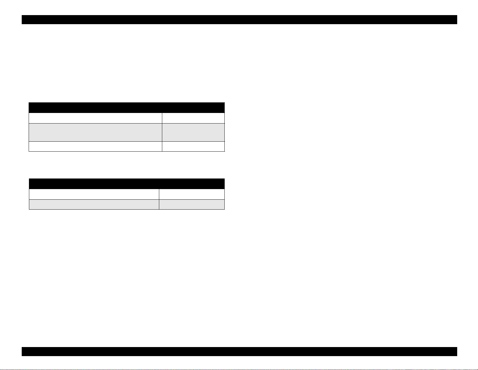
shown in Table 1-25.
Table 1-25. Relation between P-ROM and CG ROM
Destination P-ROM CG-ROM
Standard version 16 M (TFU00X) Not installed.
NLSP version 16 M (TFU00X) 16M (M160B16XA)
NOTE:The “X” in the table represents the version.
*1: The valuable dot system, or many-valued dot system, enables the
printer to freely fire three different sizes of dots (normal, middle, and
small dots) in one raster. In other printers, if the super micro dot
mode is once selected through the printer driver, the printers prints
only in the selected mode until the current print data is completed.
However, the valuable dot system of this printer enables the printer
Product Description Component Layout 37
Page 42

EPSON Stylus Color 980 Revision A
p
IC5(D-RAM)
IC4(One-time PROM)
CN15
IC3(E05B60)
CN1
CN2
IC2(E05B59)
CN4
CN5
IC1(CPU:H8S)
CN6
(IC11) PF Motor Driver
(IC12) CR Motor Driver
Thermistor (detects temperature
CN13
CN10
CN-
11
CN-
16
CN-
12
CN14
Heat Sink
of the heat sink)
Q5 (upper), Q6 (low er)
Charging/Discharging driver
for driving the black nozzles
CN9
Q3 (upper), Q4 (lower)
Charging/Discharging driver
for driving the color nozzles
CN8
Thermistor (detects temperature
on the printhead board)
IC16 (upper), IC15 (lower)
Head
re-driver
IC8(Timer & EEPROM)
Lithium Battery
IC13 (upper),
IC14 (lower)
ASF Motor Driver
Figure 1-11. C380 Main Board
Product Description Component Layout 38
Page 43

EPSON Stylus Color 980 Revision A
(
)
1.7.3 C265 PSB/PSE Board
There are two types of the C265 power supply board as listed below.
C265 PSB board:For America, Japan, part of South east Asia
C265 PSE board:The rest of all regions
W ARNING
Never touch the heat sink (radiation plate) on the Q1
with your bare hands as it is not insulated. Otherwise,
you will get an electrical shock.
The C265 PSB/PSE board uses the switching regulator system. Since
the C265 PSB/PSE board uses the power switch on the secondary side,
it keeps applying voltage to the primary side across the T1. Especially,
the heat sink to which the Q1 is attached can not be insulated due to the
circuit’s formation. Therefore, to avoid an electrical shock, be careful not
to touch the heat sink and other metallic parts simultaneously while
troubleshooting.
IC 51(+5V regulator)
D 51(D iode)
CN3
CN2
CN1
F1(Fuse)
C 1(N oise cut capacitor)
T1(Trans)
D 55(D iode)
L1
N ose cut reactance
Danger!
Q 1(FET)
C 11(for sm oothing)
Figure 1-12. C265 PSB/PSE Board
Product Description Component Layout 39
Page 44

EPSON Stylus Color 980 Revision A
1.7.4 C265 PNL Board
The C265 panel board is composed of the three switches and four
LEDs.
LED 3
LED 1
SW 2 SW 1
LED 2
CN1
1
Figure 1-13. C265 PNL Board
LED 0
SW 0
12
1.7.5 C265 Relay Board
The C265 relay board is installed to relay the following with connectors:
Power for driving motors and sensors
Control signals
If any of the connectors is connected to a wrong position during
assembly, the printer shows a fatal error at power on.
Carriage home position (CRHP) sensor
Carriage (CR) Motor
CRH PE ASF
M/C
RED
WHT
M/C
BLK
Pump/ASF Motor
Paper Feed (PF) Motor
Connector from the CN11
on the C380 Main Board
Connector from the CN12
on the C380 Main Board
Connector from the CN10
on the C380 Main Board
Connector from the CN16
on the C380 Main Board
M/C
Control Panel
ASF Sensor
PE Sensor
Solenoid (Switches ASF/PUMP
mechanism)
Connector from the CN15
on the C380 Main Board
Figure 1-14. C265 Relay Board
Product Description Component Layout 40
Page 45

OPERATING PRINCIPLES
CHAPTER
2
Page 46

EPSON Stylus Color 980 Revision A
2.1 Overview
This chapter describes the operating principles of the printer
mechanism and electrical circuits.
2.2 Printer Mechanism Operating Principles
The EPSON Stylus Color 980 has black and color heads united in one
unit which includes a total of 480 nozzles: 192 nozzles for black (96
nozzles x 2) and 96 nozzles for each color. This printhead enables the
printer to print 3 lines by one pass at 10-cpi printing. Also, new ASF/
pump switching mechanism offers higher throughput with quick feeding
motion at continuous printing by combining the trigger solenoid and
independent pump/ASF motor. Production of PTS signal using the
encoder belt also enables the printer to improve printing accuracy,
detect paper jam in the CR operational range, and print during
acceleration/deceleration (on normal paper / 360 x 360 dpi only).
See Figure 2-1 for the printer mechanism block diagram.
Operating Principles Overview 42
Page 47

EPSON Stylus Color 980 Revision A
PF drive gear (high-precision gear)
H igh-precision pinion
PF m otor
Flashing position (the 80th colum n side)
PTS encoder
Paper eject sub roller
Black I/C detection lever
C olor I/C detection lever
C R unit
U nited printhead for black and color
Tim ing belt
Cap
V a lv e fo r c a p p in g
AS F sensor (for phase detection)
ASF cam
A S F d riv e s h a ft
P a p e r lo a d r o lle r s
PE (Paper End) sensor
Pum p/ASF m otor
AS F solenoid (for switching the
AS F, pum p gear trains)
Pum p
C R H P sensor
PF roller (pow dery-coated roller)
C R guide shaft
Encoder belt
C R m otor
Figure 2-1. The Stylus Color 980 Printer Mechanism Block Diagram
Operating Principles Printer Mechanism Operati ng Principles 43
Page 48

EPSON Stylus Color 980 Revision A
2.2.1 Carriage Mechanism
As shown in Figure 2-1, the carriage unit with the printhead on it moves
right and left, depending on the rotational direction of the CR (Carriage)
motor. Table 2-1 shows the CR motor specifications.
Table 2-1. CR Motor Specifications
No. Item Specifications
1 Motor Type 4-phase / 200-pole / HB-type stepping motor
2 Drive voltage 42 VDC
3 Coil resistance 5.8
4 Drive mode Bipolar constant current drive
The CR unit position is always memorized and controlled by the CRHP
(Carriage Home Position) sensor. This sensor confirms the CR position
to renew the memory at the following timing:
When power is turned on / off
When a head cleaning operation, including initial ink charge, is
performed.
When the printer returns to a ready status because the printer
has executed print job or receives no data for one second or
more.
See Table 2-2 and Table 2-3 which show the CRHP sensor
specifications and CRHP sensor switch mode, respectively.
±
5% (Applied to the driver)
Ω
±
10%
Table 2-2. CRHP Sensor Specifications
No. Item Specifications
1Type
2 Drive voltage 5 V ± 5%
3 Collector resistance 30 VDC or less
Photo-electrically transfer system
(SHARP GP1S73P2)
Table 2-3. CRHP Sensor Switch Mode
CR Position Switch mode Sensor output
Within the CRHP
range
Off the CRHP range Close 2.4 VDC or more
Open 0.7 VDC or less
If this sensor is defective or does not work, it does not detect the
carriage while the carriage is in the home position seek mode. In this
case, the printer cuts off electricity to the CR motor and shows a fatal
error.
Like the Stylus color 900, the Stylus color 980 also uses a linear
encoder to obtain secure carriage movement and accurate print timing.
The linear encoder reads slits on the encoder belt (linear scale) above
the timing belt to control the carriage. See Table 2-4 for the linear
encoder specifications.
Operating Principles Printer Mechanism Operati ng Principles 44
Page 49

EPSON Stylus Color 980 Revision A
Table 2-4. Linear Encoder Specifications
No.
1 Type Radiative Incremental encoder module
2 Drive voltage 5 VDC ± 5%
3
4 Minimum step 1/180 inch (increment of the lines on the linear scale)
5
Item Specifications
Output
waveform
Response
frequency
Phase A/B 2-channel digital output (TTL level)
20 KHz
The ASIC (IC2) reads the linear scale (increment: 1/180 inch) and
internally divides data by 8. The read information is used to produce
basic drive frequency for 2880-dpi trapezoidal waveform production.
If the encoder is defective or in an undetectable condition, the printer
generates a fatal error immediately after power on. This error occurs
before the carriage’s home position seeking operation.
Beside detecting the carriage position, the CRHP sensor also serves to
determine whether or not the carriage is working properly. If the setting
signals (pulses) sent from the encoder do not reach the specified level
while the CR is moving in the acceleration / constant / deceleration
modes in its operative range, the program consequently assumes that
paper is jamming or the carriage is operating irregularly, and shows the
paper jam error by bringing up the LEDs of the corresponding
combination.
Table 2-5. Ink Cartridge Sensor Specifications
No.
1 Detection type
2 Rated voltage 5 VDC ± 5%
3 Rated current 10 mA
4 Contact resistance 50 m
Item Specifications
Using a micro switch
Ω
Table 2-6. Ink Cartridge Sensor Switch Mode
Cartridge
Absent Open 2.4 VDC or more
Present Closed 0.7 VDC or more
Sensor Status Sensor Output
If the ink cartridge sensor is defective or in an undetectable condition,
the printer shows No Ink Cartridge Error immediately after the printer is
turned on.
The printer is equipped with 2 accouters used to detect the ink
cartridges in the carriage unit driven by the CR motor. The printer,
however, is designed to operate the accouters only when both black
and color ink cartridges are installed. See Table 2-5 and Table 2-6 for
the ink cartridge sensor specifications and ink cartridge sensor switch
mode, respectively.
Operating Principles Printer Mechanism Operati ng Principles 45
Page 50

EPSON Stylus Color 980 Revision A
2.2.2 Printing Mechanism
The printing mechanism of the printer is all included inside the
printhead. The printing method is EPSON-exclusive MACH system,
which is used in other EPSON ink jet printers, but the printhead is not
compatible with any other printer. See Figure 2-2 for the printing
mechanism block diagram.
N o z z le
Cavity
ozzle P late
PZT
Selector
Tem perature
detection
circuit
N o zzle
Latch
circuit
P re Driver
Pulse
D is-charge
Pulse form com m and
Data
Driver
Charge
Latch
Tem perature data
Figure 2-2. Printing Mechanism Block Diagram
The printing mechanism performs printing by applying voltage to the
PZT (integrated piezoelectric element) inside the printhead. With the
voltage applied to the PZT, the cavity, a tank filled with ink, is pressed
by the PZT and ejects ink from nozzles as the result. Unlikely to the
illustration, the actual number of the PZT included in the printhead in
this printer is 480, the same number as nozzles, and each PZT is
independently driven.
The steps below describes how the printing mechanism works.
1. Head drive pulse form command signal is output from the ASIC after
the printer is turned on.
+42
ASIC
2. Receiving the signal, the Pre-driver outputs the head drive pulse
signal to the driver.
3. If no printing data is sent, pulse output from the driver is not applied
to the PZT in the printhead: because the transistor on the nozzle
selector is not on.
4. If any printing data is sent from a PC, 5 serial data (3 for Y, M, and
C, and 2 for 2 rows of black) are sent to the nozzle selector from the
ASIC. Each serial data consists of 96 data since each row is
composed of 96 nozzles. When these data is all transferred, a Latch
signal is output from the ASIC to the nozzle selector after specified
period of time.
5. When the Latch signal is sent, a PZT signal is applied to the base
side of the transistor via the latch circuit in the nozzle selector.
6. Head drive pulse constantly output from the driver is then applied to
the PZT by the pulse output after a set of serial data and the latch
signal are all transferred.
7. The PZT drive pulse radiates large heat since it is driven with the
basic drive frequency of 32.4 K Hz and also has such a large
amount of drive elements as 480 PZT. Therefore, the abnormal
temperature detection circuit is included in the nozzle selector to
detect temperature of each nozzle so that heat radiation stays under
the maximum level. If the circuit detects abnormally high
temperature in any nozzle row, the printer regards the condition as
an accidental printing malfunction such as dot missing, and it
automatically enters the cleaning CL2, the most powerful cleaning
cycle. See the sensor descriptions in Chapter 2 for the operations
after this cleaning. The printhead also has the thermistor in it to
subtly change the voltage level of the drive pulse in accordance with
the temperature condition in use.
Operating Principles Printer Mechanism Operati ng Principles 46
Page 51

EPSON Stylus Color 980 Revision A
[Nozzle configuration]
See Figure 2-3 for the nozzle configuration of the Stylus Color 980.
#96
#95
#94
#93
#3
#96
#95
#94
#93
360 dpi
180 dpi
#96
#95
#94
#93
#3
#96
#95
#94
#93
#3
#3
#2
#1
#2
#2
#1
#2
#1
#1
R ow A (B lack 1)
R ow B (B lack 2)
R ow C (M agenta)
Row D (Cyan)
Row E (Yellow)
2.2.3 Paper Load Mechanism
The paper load mechanism transports paper set in the hopper in the
ASF into the printer. It is operated by the ASF and the pump/ASF motor
which drive the ASF. The pump/ASF motor specifications are as shown
in Table 2-7.
Table 2-7. Pump/ASF Motor Specifications
No. Items Specifications
1 Type 4-phase / 48-pole / PM-type stepping motor
2 Drive voltage 42 VDC ± 5% (Applied to the driver)
3 Coil resistance 7.0 Ω ± 10%
4 Drive mode Bipolar constant current drive mode
The ASF rotates the semicircular roller once in reverse before
transporting paper into the printer. Along with this motion, the cam in the
semicircular roller pushes up the return lever. The return lever then
bounces up with tension spring force. As the result, some paper which
was fallen off the hopper during the previous feeding motion is all
aligned and set back in the hopper. This so called paper return
operation is performed for each paper feeding motion. Therefore, paper
loading accuracy is improved. See Figure 2-4 which shows how the
ASF feeds paper.
Figure 2-3. Nozzle Configuration
As shown in the figure, the black nozzles are aligned at 360 dpi
(vertical) and the color nozzles are aligned at 180 dpi. In the color
printing mode, only “B” row among 2 black nozzle rows is used and the
other row “A” is not used. (The same mechanism is used for the
microweave printing.)
Operating Principles Printer Mechanism Operati ng Principles 47
Page 52

EPSON Stylus Color 980 Revision A
[
]
After a paper loading motion is completed, the semicircular roller rotates
in the normal direction to load the top paper in the stack. This operation
is enabled by the correct phase of the gears in the ASF, because the
timings for the semicircular roller’s contacting the paper surface by the
corner (A) and the hopper’s being pushed out must be coincided. The
ASF sensor is used to determine the condition whether the phase is
correct or not. The transmission system of the ASF sensor detects the
condition by catching the position of the cam attached onto the same
shaft as the semicircular roller is. See Table 2-8 and Table 2-9 for the
ASF sensor specifications and its switch mode, respectively.
Pinch roller
Sem icircular
ro lle r
Cam
H opper
3)
4)
A
1)
2)
R e tu rn le v e r
[R e a d y s ta tu s ]
Separation pad
A c tiv e S ta tu s
Figure 2-4. ASF Paper Load Mechanism
Table 2-8. ASF Sensor Specifications
No.
1Type
2 Collector voltage 30 VDC or less
3 Coil resistance 5 VDC
Item Specifications
Photoelectric transfer system (transmission
type)
±
5%
Table 2-9. ASF Sensor Switch Mode
ASF Position Sensor Status Sensor Output
Home position Open 0.7 VDC or less
Off the home
position
Close 2.4 VDC or more
Note that torque from the pump/ASF motor is transmitted to the pump
unit depending on the pump/ASF mechanism condition. The rotational
directions and corresponding functions are as shown in Table 2-10.
Table 2-10. ASF/Pump Motor Functions
Direction Functions for ASF
Normal rotation
(CW)
Reverse rotation
(CCW)
• Reverse rotation of the
paper loading roller
(paper return control)
• Connection to the ASF
gear train
• Normal rotation of the
loading roller (paper
separation, paper
loading)
Functions for the ink
system
• Connection to the pump
gear train
• Normal rotation of the
pump (absorption)
• Releases the CR lock.
• Sets the wiper.
• Reverse rotation of the
pump motor
• Locks the CR.
• Resets the wiper.
Operating Principles Printer Mechanism Operati ng Principles 48
Page 53

EPSON Stylus Color 980 Revision A
2.2.4 Paper Feed Mechanism
The paper feed mechanism manages constant paper feeding during
printing through to paper ejection. Unlike previous models, the PF motor
of this printer only drives the paper feed mechanism, having no
connection with the carriage lock mechanism nor the pump mechanism.
See Figure 2-5 and Table 2-11 for the cross section of the paper feed
mechanism and the PF motor specifications, respectively.
Table 2-11. PF Motor Specifications
No. Items Specifications
1 Type 4-phase / 200-pole / HB-type stepping motor
2 Drive voltage 42 VDC ± 5% (Applied to the driver)
3 Coil resistance 8.1 Ω ± 10%
4 Drive mode Bipolar constant current drive mode
For the printer-specific feature, the PF motor pinion transfers torque to
the PF drive gear without any transmission gear in between. The gears
used for the PF motor pinion and the PF drive gear are very precise.
Therefore, note the points below when handling them:
See Table 2-12 and Table 2-13 for the PE sensor specifications and the
PE sensor switch mode, respectively.
Table 2-12. PE Sensor Specifications
No.
1Type
2 Drive voltage 5 VDC
3 Collector resistance 30 VDC or less
Item Specifications
Transmission-type photoelectric transfer
system
±
5% (Applied to the driver)
Table 2-13. PE Sensor Switch Mode
Paper
installation
Not installed Open 0.7 VDC or less
Installed Closed 2.4 VDC or more
N otched roller
Switch mode Output voltage
Paper
Actuator
PE sensor
Sub roller
1. Do not touch the gear surface with your bare hands.
P F d riv e g e a r
2. Keep other parts or tools for servicing such as screw drivers away
from the gears.
The PE sensor in the paper feed mechanism is used to check the
following:
1. During paper loading, checks if the leading edge of the paper from
the ASF is correctly transported.
2. Checks if the paper loaded meets the specifications.
Paper ejection
ro lle r
PF (pow dery-coated)
ro lle r
PF m otor pinion
3. Checks if the paper is properly ejected after printing is over.
4. Checks if paper is jamming.
Figure 2-5. Paper Feed Mechanism
Operating Principles Printer Mechanism Operati ng Principles 49
Page 54

EPSON Stylus Color 980 Revision A
2.2.5 Pump/ASF Switch Mechanism
The pump/ASF switch mechanism switches the motor’s torque between
the paper-loading and the pump-system sides. The pump/ASF motor
supplies torque, and a solenoid is used as switching trigger. (Refer to
Section 2.2.3 for the pump/ASF motor specifications.) Figure 2-6 shows
how the pump/ASF mechanism works when switching to the ASF gear
train.
Switching to the ASF gear train]
[
R eduction gear
AS F transm ission gear
Pum p/ASF m otor
Planetary gear set
Figure 2-6 shows the gear condition after switching to the ASF is
completed. The steps below describe how the gears move to switch
from pump gear train to the ASF gear train.
1. In the pump gear train condition, the gear (3) in the planetary gear
set and the pump transmission gear are in mesh.
2. The pump/ASF motor rotates in the normal direction (CW).
3. The whole planetary gear set tries to move up, but the solenoid
suppresses it.
4. The solenoid comes on, allowing the whole planetary gear set to
move up. At this point, the gear (3) does not rotate, but the motor
pinion gear and gear (2) rotate in mesh.
5. The gears (3) and (4) come in mesh and connection to the ASF gear
train is fixed when a corner of the solenoid is aligned with the notch
in the planetary gear set.
6. Then the gears (4) and (5) are meshed. The gear (5) is connected to
the ASF drive gear in the printer mechanism to rotate the roller in
the ASF reverse (for paper return mechanism). (Refer to Section
2.2.3 for the paper return mechanism.)
Solenoid
Pum p transm ission gear
Figure 2-6. Switching Operation to the ASF Gear Train
Operating Principles Printer Mechanism Operati ng Principles 50
Page 55

EPSON Stylus Color 980 Revision A
[Switching to the pump gear train]
Figure 2-7 shows the gear condition after switching to the pump gear
train is completed.
AS F transm ission gear
Pum p/ASF m otor
Solenoid
The steps below show how the gears move to switch from the ASF gear
train to the pump gear train.
7. In the ASF gear train condition, the gears (3) and (4) are in mesh.
8. The pump/ASF motor rotates reverse (CCW).
9. The planetary gear set tries to move down, but the solenoid
prevents it.
10. The solenoid comes on allowing the whole planetary gear set to
move down. At this point, the gear (3) does not rotate, but the motor
pinion gear and the gear (2) rotate in mesh.
11. The gears (3) and (4) come in mesh, and the connection to the
pump gear train is fixed when a corner of the solenoid is aligned
with the notch in the planetary gear set.
12. The gear (4) meshes with the pump transmission gear in the printer
mechanism to perform CR lock and pump drive operations.
Planetary gear set
Pum p transm ission gear
Figure 2-7. Switching to the Pump Gear Train
Operating Principles Printer Mechanism Operati ng Principles 51
Page 56

EPSON Stylus Color 980 Revision A
2.2.6 Pump / Carriage Lock / Head Cleaner Mechanism
The pump mechanism operates in accordance with the carriage lock
and head cleaner control mechanisms. Figure 2-8 illustrates the
process of torque transmission from the pump/ASF motor to each
mechanism.
P ressure roller
(le ft)
Unlocked
Locked
In the pum p gear train condition
O n the
s a m e s h a ft
P ressure roller
(rig h t)
Clutch
Spacer
C om pression spring
C leaner head
Pum p transm ission gear
Pum p interm ittent gear
Fram e
Figure 2-8. Pump / Carriage Lock / Head Cleaner Mechanism
Operating Principles Printer Mechanism Operati ng Principles 52
Page 57

EPSON Stylus Color 980 Revision A
The steps below explain the process of driving each mechanism.
1. The precondition for driving the pump, carriage lock, and head
cleaner is that the pump/ASF switch mechanism is switched to the
pump gear train. (Refer to Section 2.2.6.)
2. Drive from the pump/ASF motor is transmitted via:
1) pump transmission gear (black)
(black)
→
3) pressure roller (right) (pump drive roller: flesh color)
→
2) pump intermittent gear
3. Along the way, the drive is also transmitted to the carriage lock
lever. The carriage lock lever is released with normal rotation of the
Separator
pump/ASF motor and set with reverse rotation of the motor.
4. Once the drive is transmitted to the pressure roller (right), all parts
used to drive the pump begin to act. The Stylus Color 980 has the
right and left pressure rollers. However, since the black and color
heads are included in one unit, the absorption tube is split in the
middle so the 2 pumps can absorb ink in the printhead. See Figure
CW
CCW
2-9 which explains the ink absorption process.
5. The cleaner head is located between the pump frame and the
cleaner head drive roller, and a compression spring is set between
the cleaner head and the cleaner drive roller. Since the cleaner
head has a protrusion (marked with a red circle in Figure 2-8) on it
Figure 2-9. Ink Absorption Process
on the roller side, it moves back and forth along with the roller
rotation. However, if the roller rotates faster than the specific level, it
rotates alone because tension of the compression spring does not
work any more.
Operating Principles Printer Mechanism Operati ng Principles 53
Page 58

EPSON Stylus Color 980 Revision A
2.3 Electrical Circuit Operation Principles
The Stylus Color 980 consists of the following circuit boards:
C380 main board
C265 PSB/PSE board
C265 Panel Board
2.3.1 C265 PSB/PSE Power Supply Board
This section explains the operating principles of the C265 PSB/PSE
board, in order.
AC power supply voltage is supplied from the AC power socket. Then
the fuse (F1) limits the incoming current of the AC voltage to avoid
damaging the C380 main board and C265 PSB/PSE board. On the
other hand, TH1 and TH2 serve to convert surplus input voltage into
heat energy.
The input voltage is next input to the RLC parallel circuit (a filter circuit),
for higher harmonics absorption. This operation keeps the higher
harmonics in the AC power out of the printer, and also prevents leakage
of higher harmonics generated in the printer.
After noise is removed, the AC voltage goes through the full-wave
rectification circuit. The minus component of the alternate wave is
eliminated as the result.
Then the voltage is smoothed by the electrolysis condenser (C11) for
stabilized DC voltage, and the current is applied to the primary side of
the transformer (T1).
The current, however, does not flow into the primary side of the
transformer (T1) if the main switching FET (Q1) located in the primary
side is off. The Q1 comes on when the voltage is applied to the gate
through the R28, a starting resistor, when the printer is turned on. While
the Q1 is on, current does not flow into the secondary side; because a
reverse-characteristics diode is used to connect to the secondary side.
The transformer (T1) is gradually charged with the current. When it is
full and not charged any more, the gate voltage of the Q1 starts going
down gradually. At this point, C13 abruptly pulls in the gate voltage of
the Q1 to turn the Q1 off.
Operating Principles Electrical Circuit Operation Principles 54
Page 59

EPSON Stylus Color 980 Revision A
Once the Q1 is off, the energy charged in the primary side flows into the
secondary side all at once. This occurs because the energy transfers in
the same direction as the reverse diode characteristics with the Q1 off.
The secondary side of the transformer (T1), which has the specified
numbers of coiling lines for 42 VDC production, creates the 42 VDC out
of the energy led to the secondary side by the electromagnetic
induction.
The secondary side has numbers of stabilizing circuits to output
stabilized voltages, as listed below:
Smoothing circuit:
Since the energy led from the transformer (T1) to the secondary
side by the electromagnetic induction is alternating current, it
must be smoothed by the electrolysis condensers C51 and C52
to be direct current.
+42 V line constant voltage control circuit:
7 zener diodes (ZD51, ZD81 - ZD86) connected in series
monitors +42 V status used to drive various mechanisms. To
keep the output voltage at a constant level, the circuit controls
the on/off timing of the Q1 slightly according to the signals fed
back from the photocoupler (PC1).
+5 VDC by changing output pulses in spite of diverse input
voltage levels. This operation serves as a constant voltage
control circuit.
+5 V line overvoltage protection circuit:
ZD53 in the circuit monitors the +5 V line for overcurrent. In case
the voltage rises to 7 V for reasons such as a defective board,
the circuit shuts the Q1 gate in the same process as the +42 V
line overvoltage protection circuit follows.
Voltage drop delay circuit at power off
The C265 PSB/PSE board uses the secondary switch that
includes the delay circuit. The delay circuit allows the printer to
complete the power off operation properly even though the
printer is turned off while it is printing.
A normal power off operation by the user is monitored by the
C380 main board. When it detects a power off, the program
immediately starts the power-off sequence, capping the
printheads, and drops the power.
The electrolysis condenser (C84) continues to operate to allow
the printer to execute this proper power off sequence.
See the following page for the electrical circuit diagram.
+42 V line overvoltage protection circuit:
This circuit includes 2 zener diodes (ZD52, ZD87) connected in
series. It monitors the +42 V line used to drive various
mechanisms to detect abnormal rise in the voltage level caused
by a defect in the circuit. If the output voltage rises to +48 V, the
signal is input to a port of one of the 2 channels in the
photocoupler (PC1) to completely cut off the Q1 operation. Once
this circuit is active, a normal flow does not recover unless the
printer is turned off and back on.
+5 VDC production circuit:
L4960 (IC51) produces +5 VDC out of +42 VDC. Since the IC
internally operates PWM control, it can always produce constant
Operating Principles Electrical Circuit Operation Principles 55
Page 60

EPSON Stylus Color 980 Revision A
In c o m in g c u rre n t p r o te c tio n
H igher harm onics absorption
F1
L
R1
C1
TH1, TH 2
N
In ru s h c u rre n t te m p e ra tu re c o n v e rs io n
R28
300 K
Starting resistor
Main
S w itc h in g
Q1
Q31
C13
Feed
back
Q2
Feed
b a c k
L1 C3,C4
T1
Q3
Sm oothing
C2
DB1
Full w ave rectification
+5 V R egulator
1
In
L4960
7
(IC 51)
5
OSC
D51
Sm oothing
C 51,52
ZD 51,
ZD 81-86
C
H igher harm onics absorption
Sm oothing
L51
+
Out
C54
GL
+5V /1.5A
+5
PSC
+5
+5
GL
5V line overvoltage protection
GP
ZD53
ZD52
+42V/0.8A
+42
+42
+42
GP
ZD87
PC1
C84
+
C om es on w hen abnorm al.
Photo C oupler
42 V line constant voltage control
Voltage drop delay circuit at pow er off
Q84
4 2 V lin e o v e rv o lta g e p ro te c tio n
Figure 2-10. C265 PSB/PSE Board Circuit Block Diagram
Operating Principles Electrical Circuit Operation Principles 56
Page 61

EPSON Stylus Color 980 Revision A
r
2.3.2 C380Main Board
See Figure 2-11 for the C380 main board block diagram.
C90A09
(IC1)
CN4
USB
CN13
FAN
CN16
ASF Solenoid
PROM
(IC4)
Q7
Q9
D-RAM
(IC5)
CRU1
M-RAM
(IC6)
E05B59
(IC2)
A3957(IC13)
A3957(IC14)
CXA2128(IC15)
CXA2128(IC16)
E05B60
(IC3)
T93C56
(IC7)
Timer
/RST
74LV161284
(IC9)
CN12
ASF motor
CN8
Head 1
CN9
Head 2
CN15
Sensors
CN2
Type B I/F
CN1
Centronics
LB1847(IC11)
LB1847(IC12)
RTC9810
(IC8)
CN10
PF motor
CN11
CR moto
Figure 2-11. C380 Main Board Block Diagram
Operating Principles Electrical Circuit Operation Principles 57
Page 62

EPSON Stylus Color 980 Revision A
The following tables list the major components on the C380 main board
and their functions.
Table 2-14. Major Components on the C380 Main Board (1/2)
Component Functions
• A EPSON’S CPU.
CPU:
ASIC 1:
(E05B60: IC3)
ASIC 2:
(E05B59: IC2)
PROM/MROM:
D-RAM:
Timer IC:
(RTC9810: IC8)
• Performs high-speed data processing running at 24.0
Mhz with an external transmitter.
• Bus width is 16-bit.
• Controls all interfaces but USB.
• Monitors the signal from each sensor.
• Controls printheads, motors, ASF solenoid, cooling fan,
USB I/F, and EEPROM.
• For PROM, either one-time PROM or Mask ROM is
used. Specifications vary depending on the
destinations, as shown below:
<Standard version>
• PROM size: 16 M bit
• Contents: Unattached
• Bus width: 16 bit
<NLSP version>
• PROM size: 16 M bit
• Contents: 16 M bit
• Bus width: 16 bit
• Manages the various buffers and work area.
• Bus width is 16 M bit.
• Counts total power off time of the printer, which offers
the basis for determining the cleaning type to be
performed at the next power on. Power is supplied by
an external button-cell battery (a lithium battery). This
IC also serves to produce reset signals connecting to
each major IC, such as CPU, ASIC1, ASIC 2, and motor
drive ICs. The head driver ICs (CXA2128 x 2: IC15 and
IC16) individually produce a reset signal when detecting
abnormal voltage so the printhead can stop in the
proper sequence.
Table 2-15. Major Components on the C265 Main Board (2/2)
Component Functions
• The LB1847 (IC11 and IC12) is used to drive PF motor
and CR motor and enables 4W1-2 phase excitation
mode for the first in EPSON line. This control system,
called micro stepping, materializes the control of the
Motor driver IC
(LB1847: IC11, 12)
(A3957: IC13, 14)
Head driver IC
(CXA2128 x 2: IC15,
16)
carriage vibration during printing and improvement of
accuracy in paper feeding on the hardware basis.
• The A3957 (IC13 and IC14) used to drive Pump, ASF
motor also supports the 4W1-2 phase excitation mode on
the hardware basis, but differs from the former IC in the
point that the IC13 and IC14 individually excite the phase
A and B.
• The head driver ICs, directory attached to the board,
consist of two separate circuits; charging circuit and
discharging circuit, to produce trapezoidal waveform.
This IC creates the trapezoidal waveform by combining
the signals input from the input port E05B59 (IC2) of the
IC. This is performed to change the characteristics and
voltage levels of charging and discharging, and the
trapezoidal waveforms specific to normal dot print and
micro dot print are produced as the result.
Operating Principles Electrical Circuit Operation Principles 58
Page 63

EPSON Stylus Color 980 Revision A
The control circuits are explained in detail below.
[Combined (reset circuit + timer) circuit]
A combined circuit RTC9810 manages both reset signal production and
RTC (Rear Time Controller). It produces reset signals by monitoring the
both 5 VDC line (input to Pin 7) and 42 VDC line (input to Pin 9). When
the voltage level for the 5 VDC line drops to 4.3 V, or the voltage level
for the 42 VDC line drops to 35.5 V, the combined circuit outputs a reset
signal from Pin 2. When the printer is turned on / off or detects abnormal
voltage level, the IC sends the reset signal to the following ICs to avoid
printer damage caused by run-away of the logic line and abnormal
operation of driver systems. Also, to let the motor driver IC execute its
+42 V
R18 107 K
Devision
R20 10 K
81
/RST
Dropsto35V
+5 V
BAT1
43
/RST
Speed up
diode
job properly, the reset signal is once input to the convertor (setting
current production IC) on the main board to stop motors in the correct
sequence.
On the other hand, the timer control is done by counting the operation of
the oscillator circuit, and the printer’s power off time can be confirmed
based on the timer at the next power on operation. Also, this count data
is used to manage the timer for the operation such as periodical flashing
during power on time as well as power off time.
While the printer is on, the printer supplies 5 V (input to Pin 7) to operate
the internal oscillation circuit, however, when the printer is turned off,
the external button-cell battery (a lithium battery) immediately starts
supplying voltage (3 V) to the Pin 8.
9
VIN
7
VDD
RTC9810(IC8)
3.0 V
14
8
VBK
GND
DATA
SCLK
/RST
2456
36
TDATA
/RST
CE
TCE
TCLK
252627
C90A09(IC1)
M62383(IC17)
12
/RST
D/Axx
D/Axy
D/Ayx
E05B59(IC2)
3
8
4
2
13
2
13
E05B60(IC3)
VREF1
VREF2
VREF1
VREF2
LB1847(IC11)
LB1847(IC12)
3
3
REF
REF
A3957(IC13)
A3957(IC14)
Figure 2-12. Reset/timer combined circuit
Operating Principles Electrical Circuit Operation Principles 59
Page 64

EPSON Stylus Color 980 Revision A
[Sensor circuit]
The sensors attached to the printer are as described in the following
pages. They are basically divided into 2 major parts: 1) abnormal
temperature detection part and 2) mechanism status detection part. The
former is controlled by the CPU and the latter is controlled by 2 ASICs;
E05B59 (IC2) and E05B60 (IC3).
Thermistor on the heat
sink on the main board
Location (TH 1) on the board
CN8
19
21
20
1
2
9
10
HDSAMI
HPDSAMI
THM
ANODE1
ANODE2
ANODE3
ANODE4
4
CN9
ANODE5
C90A09(IC1)
AN7
AN6
AN5
AN4
AN3
AN2
AN1
AN0
112
111
110
109
108
107
106
105
1) Abnormal temperature detection part
This abnormal temperature detection part is composed of 3 thermisotrs
and the temperature detection circuit which is included in the nozzle
selector inside the printhead. The CPU’s analog ports used for
temperature detection and their functions are as follows:
Row A
Printhead surface
Row B
Row C
Row D
Row E
Inside the printhead
THM
Nozzle
Selector
Figure 2-13. Sensor Circuit Block Diagram (Abnormal Temperature Detection Circuit)
Operating Principles Electrical Circuit Operation Principles 60
Page 65

EPSON Stylus Color 980 Revision A
AN7 (Pin 112)
The TH1, located between 2 pre-driver ICs (the head driver ICs;
IC15 and IC16) on the main board, monitors temperatures around
the board. A Pre-Driver IC is exclusively developed to create
intricate trapezoidal waveforms which vary depending on the model.
It uses +42 VDC and high frequency to produce trapezoidal
waveforms. Therefore, if any relevant trouble has occurred, it is
assumed that the driver is overheated. The TH1 works to detect this
kind of unexpected rise in temperature at an early stage and stop
printing.
AN6 (Pin 111)
Four power transistors (Q3 - Q6) used for trapezoidal waveform
production are directly attached with screws to the large heat sink (a
radiation plate) on the main board. Since the printhead supported by
the Stylus Color 980 supports very high driving frequency (28.8
KHz), higher than ever, and a large amount of PZT, radiation from
the discharging transistor used for trapezoidal waveform production
is huge. Therefore, the cooling fan on the board forces out heat
around the radiation plate. A thermistor fixed on the radiation plate
sends signals to the AN6 port of the CPU to allow the CPU to
manage the cooling fan’s on/off operation.
AN5 (Pin 110)
The electrical signal input to this port is a temperature signal sent
from the thermistor included in the printhead unit. The function of
this thermistor is, same as before, to precisely detect temperatures
around the printhead and feed back information to the C380 main
board. Based on the fed back information, the printer manages
subtle change in the voltage level of the head drive trapezoidal
waveform, and also can eject the correct amount of ink as it is
aimed at any temperature.
AN4-ANO (Pins 1, 2, 9, 10, 4)
The nozzle selector IC is attached inside the printhead. It
determines which nozzle is used to fire ink according to serial data
sent from the ASIC (IC2). A temperature detection circuit included in
the nozzle selector detects the temperature of each actuator in the
5-row PZT array. This must be performed to avoid false firing. If the
printhead continues the firing motion, but no ink is ejected, the
temperature inside the printhead rises to 100
°
C and the printhead
might be damaged as a result. To prevent this from happening, the
abnormal temperature detection circuit is included in the nozzle
selector circuit.
The followings are possible reasons for false firing:
1. If an ink cartridge has been removed before its life end and is
installed again, the ink consumption counter value is upset, and
the counter fails to detect the actual remaining ink level. This
wrong operation dangerously causes the printhead to keep
firing without any ink remaining in the cartridge.
2. Serious dot missing can also cause false firing. In this case,
there is enough ink in the cartridge, but it does not properly flow
into the head because of a clogged nozzle(s). If the PZT is
driven without any ink flow, heat generated by the nozzle
movement can not be released, and this makes the
temperature around the head abnormally high.
3. Strong vertical impact applied to the head causes a
considerable amount of ink around the nozzle to leak all at
once as well as damages meniscus on the head surface. As a
result, ink does not properly eject at the next printing and ends
up in a false firing status.
Operating Principles Electrical Circuit Operation Principles 61
Page 66

EPSON Stylus Color 980 Revision A
False firing is detected in the following conditions, and the printer
handles it as described below.
False firing detection timing:
If any of the 5 channels, which are monitored by the abnormal
temperature detection circuit in the nozzle selector, reaches 100
°
C, the printer stops printing and automatically begins the
cleaning cycle. In this case, the printer runs the most powerful
cleaning cycle. The particular address bit called abnormal
temperature detection flag is reset at this point.
Process after detection:
The printer does not resume printing until the temperature
around the PZT recovers to the tolerable range. In case the
printer detects the same abnormal condition again, it indicates
an ink-end error to urge the user to replace the cartridge
considering the following possible reasons:
1. The currently installed ink cartridge is far beyond its useful
life (6 months). Ink, in this condition, does not eject properly
and results in a false firing. When a new cartridge is
installed, the problem is solved.
the more the cartridge is removed/installed, the more
bubbles are formed, and the printhead can not eject ink
properly and false firing occurs.
2. The cartridge installed has been repeatedly removed and
then installed again several times. With this mis-handling of
the cartridge, the ink consumption counter can not properly
describe the actual remaining ink level, and a false firing
occurs as a result. The solution in this case is also replacing
the ink cartridge with a new one.
Furthermore, If an ink cartridge is removed from the printer,
air comes in and bubbles inside the cartridge. Unlike a new
cartridge, the ink inside the removed cartridges is not
deaerated, so the bubbles inside can not be absorbed into
the ink due to the ink’s saturated condition. For this reason,
Operating Principles Electrical Circuit Operation Principles 62
Page 67

EPSON Stylus Color 980 Revision A
[Mechanism status detection part]
+5
+5
CN8
ENCB
93
21
LS1
E05B 59(IC 2)
E05B 60(IC 3)
ENCA
COB
COC
SW C0
SW A1
SW A0
PSC
94
109
110
137
136
135
33
+5
+5
20
20
21
CN9
LS2
COB
COC
16
15
14
4
CN15
HP
PE
ASF
CN5
+5
4
PSC
Figure 2-14. Sensor Circuit Block Diagram (Mechanism Status Detection Part)
Operating Principles Electrical Circuit Operation Principles 63
Page 68

EPSON Stylus Color 980 Revision A
Encoder:
This sensor increases accuracy of ink ejection timing. Irregular
movement of the carriage, usually caused by a paper jam, can be
also detected based on the change in input signals of this sensor.
Carriage movement is monitored by running the encoder belt (with
lines printed on it with increments of 180 dpi) between the photo
sensor attached to the carriage. Also, if the printer receives a large
impact during printing, the input signal cat not be properly read, and
in some cases print quality decreases with a dot missing problem.
This is because this printer forms one dot by producing trapezoidal
head driving waveform based on the cycle determined by the
signals sent from the encoder.
Ink cartridge sensor:
If the printhead drives without any ink cartridge installed (= false
firing), it damages the printhead unit. Also, compared with other
printers, this printer uses the largest number of PZT and accordingly
releases more heat. For this reason, the ink itself inside the
cartridge serves to lower the temperature inside the cartridge, and
black and color ink cartridges can be separately detected to avoid
false firing.
Detection process: An ink cartridge is detected when the ink
cartridge being installed activates the actuators, which then pushes
the micro switch.
CR home position sensor:
When the printer is turned on, the CRHP sensor confirms the CR is
in the home position during the home position seeking sequence.
Then the printer can determine the CR control afterwards. The
printing column position is also confirmed based on the signals from
the sensor.
Detection process: The carriage is detected when the flag interrupts
the light beam in the photo sensor which is located on the right end
of the printer mechanism.
PE (Paper End) sensor:
The PE sensor detects the following conditions:
Whether or not paper is set at power on.
Whether or not paper is properly fed from the ASF with the
paper feed command.
Whether or not the printer properly ejects a page of printed
paper after rotating the PF (Paper Feed) motor with the
predefined distance.
Detection method: A photo sensor is used to detect the
actuator’s motion; the actuator is pushed/released by the
leading/rear edge of the paper.
ASF sensor:
Various parts in the ASF are engaged in the phase that is designed
to feed paper at the appropriate timing. If the timing is wrong, mismatch occurs between paper feeding by the ASF and paper
transportation for printing, and non-feeding or paper jam will occur.
Therefore, this printer monitors the sensor condition at power on
and before and after paper is fed/ejected according to the pump/
ASF motor’s rotational distance.
Power on/off detection:
Unlike primary-side switch type products, ASIC E05B60 (IC3) on the
C380 main board is used to monitor the power on/off operation
instead of any sensor. When the power switch on the control panel
is turned off, the change from 5 V to ground level is detected at the
Pin 33 of the IC3, and the program starts the power off sequence
with this change. Power used during the sequence is supplied by
the electrolysis condenser C84 in the voltage drop delay circuit in
the secondary side of the C265 PSB/PSE board. The electrolysis
condenser continues to supply power until all electric charge inside
is completely discharged.
Operating Principles Electrical Circuit Operation Principles 64
Page 69

EPSON Stylus Color 980 Revision A
2.3.3 CR Motor Driver Circuit
An exclusive motor drive IC (LB1847: IC12) enables 4W1-2 phase
excitation on the hardware basis. A micro stepping motor is used for the
CR motor to move the carriage accurately and also to improve printing
accuracy by minimizing the motor’s vibration during printing. Figure
2-15 shows the CR motor driver circuit block diagram.
+42 +42
+42
+42
E05B 59(IC 2)
Phase A setting
current signal
(16 patterns)
Phase B setting
current signal
(16 patterns)
Phase CR A (B )
sele ction signal
Phase CR A (B )
ENB (perm ission)
signal
M otor sub control
M D signal
Phase A constant
at chopping
DECAY signal 1
DECAY signal 2
N o t u s e d
CRIA0
CRIA1
CRIA2
CRIA3
CRIB0
CRIB1
CRIB2
CRIB3
CRPHAA
CRPHAB
CRENBA
CRENBB
CRCTL0
CRCTL1
CRCTL2
CRCTLR
CRCTLS
147
148
149
150
163
162
161
160
143
170
144
169
171
172
173
174
175
N.C.
25
IA 1
24
IA 2
23
IA 3
22
IA 4
18
IB 1
19
IB 2
20
IB 3
21
IB 4
27
PHASE1
16
PHASE2
26
ENABLE1
17
ENABLE2
2
VREF1
13
VREF2
3
CR1
12
CR2
1
MD
DECAY1
5
SECAY2
10
LB1847(IC 12)
OUTA
OUT-A
OUTB
OUT-B
VBB
VCC
GND
7
6
9
8
14
28
15
+5
CN11
1
2
3
4
+42
M 62383(IC 17)
8
D/Axy
OUT A
OUT-B
OUT-A
OUT B
Figure 2-15. CR Motor Driver Circuit Block Diagram
Operating Principles Electrical Circuit Operation Principles 65
Page 70

EPSON Stylus Color 980 Revision A
Unlike previous EPSON ink jet printers, the number of the phase
excitation input ports in the motor drive IC of this printer has increased
to 8. The previous micro step system used total of 4 phase excitation
input signals for both phases A and B. (Stylus COLOR, Stylus PRO
series, and Stylus PRO XL series are exceptional, since they transfer 4bit serial data from ASIC to the motor driver.) This is because the micro
stepping was controlled by the software only. On the other hand,
LB1847 enables the 4W1-2 phase excitation using the hardware and is
equipped with the necessary number of input ports (8 ports) for current
setting signals. Among these input ports, 4 ports are allocated to each
phase, A and B. Therefore, 16 types of current setting data can be
constantly sent to the driver IC. The LB1847 controls the micro stepping
system by exciting the corresponding phase based on the combinations
of the setting signals sent from the ASIC.
Table 2-16 shows the excitation modes used for the CR motor and their
usage.
Table 2-16. CR Motor Excitation Mode and Usage
Excitation mode
2-2 phase drive LQ print mode 1/120” (0.212 mm)
1-2 phase drive Not used 1/240" (0.106 mm)
W1-2 phase drive
2W1-2 phase drive
4W1-2 phase drive
Usage Minimum step
Sort skipping
SLQ print mode
Wiping
Capping
Moving from the
capping position
Uncapping
1/480” (0.053 mm)
1/960" (0.026 mm)
1/1920" (0.013 mm)
Operating Principles Electrical Circuit Operation Principles 66
Page 71

EPSON Stylus Color 980 Revision A
A
2.3.4 PF Motor Driver Circuit
Motor drive exclusive IC (LB1847: IC11) enables 4W1-2 phase
excitation on the hardware basis. A stepping motor is used for the PF
motor to move the carriage accurately and also to improve printing
accuracy by minimizing the motor’s vibration during printing. Figure
2-16 shows the PF motor driver circuit block diagram.
+42 +42
+42
+42
E05B 59(IC 2)
Phase A setting
current signal
(16 patterns)
Phase B setting
current signal
(16 patterns)
Phase CR A (B )
sele ction signal
Phase CR A (B )
ENB (perm ission)
signal
M otor sub
control
PFIA0
PFIA1
PFIA2
PFIA3
PFIB0
PFIB1
PFIB2
PFIB3
PFPHAA
PFPHAB
PFENBA
PFENBB
PFCTL0
PFCTL1
PFCTL2
PFCTLR
PFCTLS
140
139
138
137
133
134
135
136
142
128
141
129
124
127
125
126
123
N.C.
25
IA 1
24
IA 2
23
IA 3
22
IA 4
18
IB 1
19
IB 2
20
IB 3
21
IB 4
27
PHASE1
16
PHASE2
26
ENABLE1
17
ENABLE2
2
VREF1
13
VREF2
LB1847(IC 11)
OUTA
OUT-A
OUTB
OUT-B
VBB
VCC
GND
14
28
7
6
9
8
15
+5
M 62383(IC 17)
3
D/Axx
CN10
1
3
2
4
+42
PFF
PF -A
PF B
PF-B
Figure 2-16. PF Motor Driver Circuit Block Diagram
Operating Principles Electrical Circuit Operation Principles 67
Page 72

EPSON Stylus Color 980 Revision A
Unlike the previous EPSON ink jet printers, the number pf the phase
excitation input ports in the motor drive IC of this printer has increased
to 8. The previous micro step system used total of 4 phase excitation
input signals for both Phase A and Phase B. (Stylus COLOR, Stylus
PRO series, and Stylus PRO XL series are exceptional, since they
transfer 4-bit serial data from ASIC to the motor driver.) This is because
the micro stepping was controlled by the software only. On the other
hand, LB1847 enables 4W1-2 phase excitation using the hardware and
is equipped with the necessary number of input ports (8 ports) for
current setting signals. Among 8 input ports, 4 are allocated to each
phase, A and B. Therefore, 16 types of current setting data can be
constantly sent to the driver IC. The LB1847 controls the micro stepping
system by exciting the corresponding phase based on the combinations
of the setting signals sent from the ASIC.
Table 2-17 shows the excitation modes used for the PF motor and their
usage.
Table 2-17. PF Motor Excitation Mode and Usage
Excitation phase
2-2 phase drive Not used 1/720"(0.035 mm)
1-2 phase drive
W1-2 phase drive Not used 1/2880"(0.009 mm)
2W1-2 phase drive Middle-speed feed 1/5760"(0.004 mm)
4W1-2 phase drive
Usage Minimum step
Fast feed 1
Fast feed 2
Special fast feed
Normal feed
Micro adjust feed
Slow feed
1/1440"(0.018 mm)
1/11520"(0.004 mm)
Operating Principles Electrical Circuit Operation Principles 68
Page 73

EPSON Stylus Color 980 Revision A
2.3.5 Pump/ASF Motor Driver Circuit
Like for the CR motor and the PF motor, A3957 (IC13, IC14) enables
the pump/ASF motor to perform 4W1-2 phase excitation on the
hardware basis. Figure 2-17 shows the pump/ASF motor driver circuit
block diagram. Among 2 drivers, IC13 and IC14 drives the Phase A and
Phase B, respectively.
E05B 59(IC 2)
Phase A setting
current signal
(16 patterns)
Phase A specified
signal
Phase B setting
current signal
(16 patterns)
Phase B specified
signal
ASFIA0
ASFIA1
ASFIA2
ASFIA3
ASFPHAA
ASFIB0
ASFIB1
ASFIB2
ASFIB3
ASFPHAB
69
68
62
64
63
81
80
72
74
73
A3957(IC 13)
20
13
11
8
10
A3957(IC 14)
20
13
11
8
10
REF
OUTA
OUTB
OUTA
OUTB
15
22
15
22
+42
+42 +42
M 62383(IC 17)
4
D/Axy
+42
CN12
1
3
2
4
ASF A
ASF -A
ASF B
ASF-B
Figure 2-17. Pump/ASF Motor Driver Circuit Block Diagram
Operating Principles Electrical Circuit Operation Principles 69
Page 74

EPSON Stylus Color 980 Revision A
Table 2-18 shows the excitation modes used for the pump/ASF motor
and their usage.
Table 2-18. Pump/ASF Motor Excitation Mode and Usage
Excitation phase
2-2 phase drive
1-2 phase drive Micro absorption 1/1440" (0.018 mm)
W1-2 phase drive Not used 1/2880" (0.009 mm)
2W1-2 phase drive
4W1-2 phase drive
Fast absorption
Semi-fast absorption
Fast feed
Normal absorption
Normal feed
Constant drive
Slow feed
Slow absorption
Usage Minimum step
1/720" (0.035 mm)
1/5760" (0.004 mm)
1/11520" (0.004 mm)
2.3.6 Printhead Driver Circuit
The printhead driver circuit consists of 2 circuits: the common voltage
production circuit (a trapezoid waveform production circuit) on the C380
main board and nozzle selector on the printhead. The pre-driver
CXA2128 (IC15, 16) produces trapezoid waveform and the transistors
(Q3 - Q6) output it. Unlike previous products, data (serial data) is
independently transferred to each nozzle row to enable reduction in
data latch time required to form one dot, while nozzle selection is
performed by ASIC, which sends serial data directly to the nozzle
selector on the printhead synchronizing with the clock signal. (A block
diagram and the circuit diagram for the nozzle selector are not included
in this manual.) The printhead driver circuit block diagram is shown in
Figure 2-18.
Operating Principles Electrical Circuit Operation Principles 70
Page 75

EPSON Stylus Color 980 Revision A
C X A 2128(IC 15)
110
109
107
102
97
98
99
100
101
108
COC
COB
HLAT
HSOCLK
HSO_Y
HSO_M
HSO_C
HSO_B1
HSO_B2
HINV
E05B 59(IC 2)
HW A0
HW A1
HW A2
HW A3
HW CLK1
HW CLK2
/H W F L R
HW SDATA
HW SLC
/H W S L A T
114
113
112
111
120
119
118
115
116
121
28
A0
27
A1
26
A2
25
A3
3
CLK1
4
CLK2
5
/FLOOR
29
DATA
30
DCLK
1
/E
C X A 2128(IC 16)
28
A0
27
A1
26
A2
A3
25
3
CLK1
4
CLK2
5
/FLOOR
29
DATA
30
DCLK
1
/E
VCC45
VC C 45_2
NPNB
FB
PNPB
VCC45
VC C 45_2
NPNB
FB
PNPB
22
23
20
18
16
Q3
Q4
C harging/discharging
circuit for black nozzles
CPU(IC1)
AN0
110
AN5
AN1
AN2
AN3
AN4
22
23
20
Q5
18
16
Q6
C harging/discharging
circuit for color nozzles
F1
105
106
107
108
109
+42
17
5
6
13
14
19
1
2
9
10
4
21
20
17
15
13
11
9
7
6
19
1
CN8
VHV
COM a
COM b
COM c
COM d
COM e
CN9
Black nozzle row s
C o lo r n o z z le r o w s
H ead tem perature
THM
detection circuit
ANO DE1
ANO DE2
ANO DE3
ANO DE4
ANO DE5
COC
COB
I/C detection signal
LAT
CLK
Y
M
C
B1
- D a ta la tc h s ig n a l
- N ozzle selection signal
- C lock signal
B2
IN V
C o lo r n o z z le r o w
AN data
(tem perature
detection
for each color)
Trapezoid w aveform
reverse signal
Figure 2-18. Printhead Driver Circuit Block Diagram
Operating Principles Electrical Circuit Operation Principles 71
Page 76

EPSON Stylus Color 980 Revision A
2.3.7 Cooling Fan Driver Circuit
Since this printer drives a large number of PZT elements (total of 480
nozzles) with a high drive frequency (maximum 32.4 K Hz), heat
radiated around the printheads and the trapezoid waveform production
circuit on the C380 main board is considerably large compared to other
printers. Therefore a thermistor is attached to the heat sink fixed to the
trapezoid waveform production transistors to prevent the trapezoid
waveform production transistors (Q3 - Q6) and adjacent HIC from
operating abnormally due to high temperature. When the thermistor
detects abnormally high temperature, the printer turns the cooling fan
on to forcibly blow out heat from the lower case. Figure 2-19 shows the
cooling fan driver circuit block diagram. Table 2-19 shows how the
signals output from the ASIC and corresponding fan conditions.
+42
6.8
E05B 59(IC 2)
176
FAN
Figure 2-19. Cooling Fan Driver Circuit Block Diagram
D rops to 35 V.
39 K
F6
CN13
1
2
+35
GND
FAN
Figure 2-20 shows the main routine of the cooling fan drive.
Start
Is
the fan
rotating?
NO
t1 >/= 40°C
or
t2 >/= 50°C
NO
t1 >/= 36°C
or
t2 >/= 42°C
NO
t1 = Heat sink temperature on the C380 main board
t2 = TH1 temperature on the C380 main borad.
YES
YES
YES
t1 >/= 50°C
or
t2 >/= 55°C
NO
Fan Off
YES
Error 1
t1 >/= 60°C
or
t2 >/= 60°C
NO
Fan On
YES
Error 1
Table 2-19. Cooling Fan Control by the ASIC (IC2)
ASIC (IC2, 176- pin) condition Cooling fan condition
Return to the Start.
High (5 VDC) On
Low (0 VDC) Off
Operating Principles Electrical Circuit Operation Principles 72
Figure 2-20. Main Routine of the Cooling Fan Drive
Page 77

EPSON Stylus Color 980 Revision A
Whether or not the cooling fan is driven depends on the electrical
signals sent from the 2 thermistors (“t1” and “t2” in the figure). The “t1”
represents the temperature detected by the thermistor attached to the
heat sink on the C380 main board with a screw, while the “t2”
represents the one between the printhead pre-driver ICs (IC15 and
IC16) on the C380 main board. Table 2-20 shows the thermistor
condition and corresponding fan operation.
Table 2-20. Conditions for Driving the Cooling Fan
Thermistor condition
t1 and t2 have detected
temperatures.
Cooling fan:
Operating
≥ °
40 C or t2 ≥ 50 °Ct1 ≥ °36 C or t2 ≥ 42 °C
t1
Cooling fan:
Stops operating.
Even while the printer is in idle status, the thermistors continue to detect
temperatures every 2 seconds for the cooling fan operation. However, 2
error status conditions can be detected in the main routine, since air
may not cool down if the fan is defective or the ventilation grill is
clogged.
[Error 1]
The printer does not stop printing but continues to print by lowering the
drive frequency. For instance, the printer normally prints with the head
drive frequency of 14.4 K Hz to perform 1440-dpi print (horizontal) at
200 cps (CR speed). In the error condition, however, the printer can
lower the head drive frequency to 7.2 K Hz by reducing CR speed to
100 cpi. Note the printer actually performs printing at 1/3 duty / 1-pass
of a normal speed.
completely. Therefore, this printer specifically shows a fatal error on the
control panel when detecting abnormal temperatures in addition to the
following 2 common conditions.
1. Failure in CR home position detection:
This failure can be caused by one of the following 4 reasons:
- CRHP sensor itself is defective.
- There is a deficiency in the circuit.
- Incorrect PG adjustment
- CR motor is defective
2. Failure in ASF home position detection:
This failure can be caused by one of the following reasons:
- ASF sensor itself is defective.
- There is a deficiency in the circuit.
- ASF is damaged.
- Pump/ASF motor is defective.
[Error 2]
The printer stops printing. In this condition, the temperature at the
junction of the power transistor for trapezoidal waveform production and
the trapezoid waveform production IC (pre-driver) has risen to the limit
(which means the thermistors have detected over 60
°
C at both t1 and
t2), and the printer generates a fatal error after stopping printing
Operating Principles Electrical Circuit Operation Principles 73
Page 78

EPSON Stylus Color 980 Revision A
2.3.8 ASF Solenoid Driver Circuit
A planetary gear is used in the gear train which switches between paper
feed operation from the ASF and pump operation. The switching action
is enabled by the solenoid. See Table 2-21 and Figure 2-21 which show
ASF solenoid specifications and the ASF solenoid control circuit block
diagram, respectively.
Table 2-21. ASF Solenoid Specifications
No. Items Specifications
+42
F4
1 Type Single-phase DC solenoid
2 Drive voltage 42 VDC ± 5%
3 Coil resistance 588 Ω ± 10% (at 20 °C)
4 Induction 0.98 N (100 gf) or more
Table 2-22 shows the ASIC’s (IC2) conditions for driving the ASF
solenoid.
Table 2-22. Conditions for Driving the ASF Solenoid
ASIC’s (IC2, 83-pin) condition Solenoid’s condition
High (5 VDC) Inducting
Low (0 VDC) Non-inducting
E05B 59(IC 2)
ASF_SO L
83
Q9
Q8
CN16
2
1
Figure 2-21. ASF Solenoid Control Circuit Block Diagram
C ooling fan
GND
VBB
Operating Principles Electrical Circuit Operation Principles 74
Page 79

EPSON Stylus Color 980 Revision A
2.3.9 EEPROM Control Driver Circuit
Data for various factory-adjustment items is stored in the EEPROM
(IC7) on the C380 main board. The size of the EEPROM is 2 K bit since
various types of dots are available with this printer and memory
allocated for the ink consumption counter is accordingly large.
When the printer is turned on, data stored in the EEPROM is transferred
to the D-RAM by the ASIC (IC3). In the D-RAM, the ASIC controls
various adjustment values, total ink consumption, and current ink usage
condition for each color, and the printer prints depending on these
values. When the printer is turned off, the data and adjustment values
accumulated and controlled in the D-RAM are written back into the
specific addresses in the EEPROM under the ASIC’s control.
Information is transmitted between the ASIC (IC3) and the EEPROM in
the serial data format.
+5
8
6
5
AT93C 56(IC 7)
Vcc
ORG
GND
CS
SK
DI
DO
1
2
3
4
29
30
31
32
E05A 60(IC 3)
ECS
ESK
EDI
EDO
DRAM(IC5)
Address
Data
Figure 2-22. EEPROM Control Circuit Block Diagram
Operating Principles Electrical Circuit Operation Principles 75
Page 80

TROUBLESHOOTING
CHAPTER
3
Page 81

EPSON Stylus Color 980 Revision A
3.1 Overview
This chapter describes how to troubleshoot problems. It consists of the
sections shown in the flowchart below. When identifying and
troubleshooting problems, be sure to proceed to the correct section
specified in the flowchart.
No
Isolating the faulty part
on the pow er supply
board
(S ection 3.1.2)
Is the printer pow er on?
Yes
Troubleshooting w ith
LED error indications
(S ection 3.1.1)
Following sections show detailed information on each step in the
flowchart. Be sure to perform troubleshooting without neglecting the
correct order specified in each section.
Isolating the faulty part
according to the
exhibited phenom enons
(S ection 3.1.3)
Figure 3-1. Troubleshooting Flowchart
Troubleshooting Overview 77
Page 82

EPSON Stylus Color 980 Revision A
3.1.1 Troubleshooting with LED Error Indications
This section describes how to troubleshoot the problem when the
printer indicates an error at power on and can not print. The Stylus
Color can detect the following seven errors and indicates them with the
LEDs, as shown below.
Table 3-1. Error Indication with the LEDs
Corresponding Combination of the LED Condition
Error Condition
Paper Out Error On --- --- On
Paper Jam Error --- Off Off Blink
No I/C or Ink Out
(Black) Error
No I/C or Ink Out
(Color) Error
Maintenance
Error
Fatal Error Blink On On Blink
Double Feed
Error
Power
--- On --- ---
--- --- On ---
Blink Blink Blink Blink
--- --- --- On
Ink Out
(Black)
Ink Out
(Color)
Paper Out
See the following tables which show the error conditions and
corresponding possible causes.
Table 3-2. Error Condition and the Possible Causes
No. Error Condition Possible Causes
1 Paper Out Error or
Double Feed Error
(Refer to Section
)
3.1.1.1.
2 Paper Jam Error
(Refer to Section
)
3.1.1.2.
1. Failure in paper feeding
2. Connector for the PE sensor is disconnected.
3. The PE sensor actuator is acting improperly.
The sensor base is not fixed properly.
4. The PE sensor is defective.
5. ASF is damaged.
1. The paper in use is longer than specified.
2. The encoder at the back of the carriage is covered
with dust.
3. The encoder at the back of the carriage is almost
dislocated. If it has completely come off, a fatal error
occurs.
4. The PE sensor remains on because it is covered
with paper debris or dust.
5. The PE sensor actuator is not acting properly.
The sensor base is not fixed properly.
6. The PE sensor is defective.
The encoder is defective.
7. The ASF is not installed properly.
The paper load sub roller is not fixed properly.
NOTE:“---” means the LED is not affected by the error condition.
Troubleshooting Overview 78
Page 83

EPSON Stylus Color 980 Revision A
Table 3-3. Error Condition and the Possible Causes (continued)
No. Error Condition Possible Causes
3 NO I/C or Ink Out
Error
(Refer to Section
)
3.1.1.3.
4 Maintenance
Error
(Refer to Section
)
3.1.1.4.
5 Fatal Error
(Refer to Section
)
3.1.1.5.
1. The counter is not showing the actual remaining ink
level.
2. Ink cartridge sensor actuator is not acting properly.
3. The micro switch is not mounted correctly.
The connector (green) is disconnected.
4. The connector (green, 3-pin) on the small board
directly attached to the printhead surface side is
disconnected. Note the connector (green, 4-pin) is
irrelevant as it is for the encoder.
5. The micro switch is defective.
6. The value for the ink consumption counter in the
EEPROM is destroyed.
7. Ink cartridge replace command is generated because
an abnormal temperature is detected.
Usual waste ink over-flow is requested.
Note this error can be cleared by the special function
through the control panel operation only.
1. The CRHP sensor has come off.
The connector for the CRHP sensor is disconnected.
2. The encoder belt has come off.
The encoder belt is not placed through the encoder
located at the back of the carriage.
3. The ASF sensor has come off.
The connector for the ASF sensor is disconnected.
4. The coil for the CR motor has burnt.
5. The coil for the PF motor has burnt.
6. The lever fixing the planetary gear has come of the
frame.
The tension spring is dislocated.
7. Coil for the pump/ASF motor has burnt.
8. The coil for the ASF solenoid has burnt.
9. The CRHP sensor is defective.
10. The ASF sensor is defective.
3.1.1.1 Remedies for Paper Out Error
This section provides check points and corresponding actions which are
necessary when the Paper Out Error problem has occurred because of
either of the following reasons:
Paper is set in the ASF hopper but not fed.
Paper is fed but not detected by the printer.
Be sure to follow the steps in the order described in the tables.
NOTE:If the finding for the question is Yes, take the action described in
the right column. If “No”, proceed to the next step.
Troubleshooting Overview 79
Page 84

EPSON Stylus Color 980 Revision A
M/C
M/C
CRH PE ASF
RED
WHT
BLK
M/C
Pin 3 (PE)
Pin 2 (G N D)
Table 3-4. Remedies for Paper Out Error Table 3-5. Remedies for Paper Out Error (continued)
Step Check point Actions
1 Is no paper
loaded?
Set a cleaning sheet in the ASF up side down. Then
holding the top edge, press the Load/Eject button, and
the micro pearl on the paper load roller (a semicircular
roller) surface is removed. To remove severe smear,
staple a cloth moistened with alcohol to a post card and
clean the roller in the same manner.
N on-adhesive A rea
C L S heet
Adhesive A rea
This side dow n
2 Is the connector
for the PE sensor
disconnected?
Connect the connector (yellow, 3-pin) for the PE sensor.
Bottom view of the printer m echanism
(U se a post card
for the base sheet.)
Staplers
C loth m oistened
w ith alcohol
Step Check point Actions
4 Is The PE sensor
defective?
Measure the voltage at the yellow 3-pin connector
on the relay board by activating the actuator
manually to check that the voltage is correct as
follows.
The actuator is activated: 2.4 V or more
The actuator is released: 0.7 V or less
5 Is the ASF damaged? Hand-rotate the shaft in the ASF in the paper feed
direction and check if the hopper hops out every
time you rotate the shaft.
C onnector for the
PE sensor
NOTE:
Tension spring
Even though the ASF sensor is in the
proper condition for detecting the HP
sensor, If the hopper is not operating at the
correct timing for paper feeding, paper is
• Is the PE
3
sensor
actuator acting
improperly?
• Is the sensor
base floating?
• Using your hand, try activating the actuator in the
same condition as it is detecting incoming paper. Then
release the actuator and check if the actuator
automatically returns to its original position with the
tension of the spring.
• Referring to the illustration above, check that the
sensor base is securely installed to the frame. If the
sensor base is floating or installed insecurely, instal it
securely.
not loaded. Therefore, if the ASF sensor is
working without this correct combination,
reassembly or replace the ASF.
Troubleshooting Overview 80
Page 85

EPSON Stylus Color 980 Revision A
Linear Scale
(Encoder belt)
Encoder
C arriage U nit
PE Sensor
Actuator
PE Paper G uide
A ssem bly (R ight)
PF R oller
3.1.1.2 Remedies for the Paper Jam Error
This section includes the check points and corresponding actions which
are necessary when the Paper Jam Error constantly occurs when the
printer is turned on or feeding paper.
Be sure to follow the steps in the order described in the tables.
NOTE:If the finding for the question is Yes, take the action described in
the right column. If “No”, proceed to the next step.
Table 3-6. Remedies for Paper Jam Error
Step Check Points Actions
1 Is the paper length
beyond the
specifications?
2 Is the encoder located
at the back of the CR
covered with dust?
3 Is the encoder belt
nearly dislocated from
the encoder?
Instruct the user that the Paper Jam Error occurs
if paper whose length is beyond the specifications
is used.
Check if there is any dust or paper debris lodged
between the parts of the encoder (a transmission
type photo sensor) located at the back of the
carriage.
Referring to the illustration above, check if the
encoder belt is nearly dislocated from the
encoder.
Troubleshooting Overview 81
4 Is the PE sensor always
on because of the paper
debris or dust
accumulated over the
sensor.
Viewing the PE sensor from the front, check that
the actuator is the correct position: the actuator
falls in the cutout without any paper.
Page 86

EPSON Stylus Color 980 Revision A
Top Fram e
Tension Spring
Table 3-7. Remedies for Paper Jam Error (continued) Table 3-8. Remedies for Paper Jam Error (continued)
Step Check Points Actions
• Is the PE sensor
5
actuator acting
Referring to Step 3 in Section 3.1.1.1 “Remedies
for Paper Out Error”, check the sensor condition.
improperly?
• Is the sensor base
floating?
• Is the PE sensor
6
defective?
• Is the encoder
defective?
Referring to Step 4 in Section 3.1.1.1 “Remedies
for Paper Out Error”, check the sensor condition.
Then, verify the encoder sensor condition by
checking the following points for proper connection
and electrical continuity, since checking the signal
directly from the encoder is impossible.
1. Connection of the connector 1
2. Connection of the connector 2
3. Electrical continuity of the cable.
C arriage view ed from the back
C onnector 1
C heck for
continuity.
C onnector 2
H ead surface
Step Check Points Actions
7 Is the ASF installed
improperly?
Is any of the paper load
• Check the ASF installation at the following 2
points: View A and View B in the figure below.
View B
sub rollers fixed
improperly?
Protrusion is set in here.
View B
D isconnected
View A
• Viewing the printer from the back, check that all
of the six torsion springs securing the paper
load sub rollers are properly installed.
View A
Troubleshooting Overview 82
Page 87

EPSON Stylus Color 980 Revision A
M icro Sw itches
Actuator 1
Actuator 2
3.1.1.3 Remedies for No I/C and Ink Out Errors
This section includes the check points and corresponding actions which
are necessary when the black ink (or color ink) LED comes on or blinks
at power on despite the ink cartridge has been replaced with a new one.
Be sure to follow the steps in the order described in the tables.
NOTE:If the finding for the question is Yes, take the action described in
the right column. If “No”, proceed to the next step.
Table 3-9. Remedies for No I/C and Ink Out Errors
Step Check Point Actions
1 Does the counter
value mis-match the
actual remaining ink
level?
2 Is the ink cartridge
sensor actuator
acting improperly?
The ink consumption counter, separately set for black
and color ink, adds up points according to ink weight
used to form one dot. This counter is reset (the value
returns to zero) when the I/C replacement sequence is
performed. If the counter is reset for any other
purposes, the following adversities will occur.
1. Enough ink is remaining in the cartridge, but the
printer shows the Ink low or Ink end condition and
can not continue to print.
2. Ink has run out but the printer continues to print and
starts false firing, which damages the printhead.
Explain the situation to the user well, and replace the
I/C with a new one.
Turn the both actuators (eight and left) manually and
check that they properly push the micro switches.
Then, also check that the actuators return to their
normal conditions shown in the figure below
automatically.
Troubleshooting Overview 83
Page 88

EPSON Stylus Color 980 Revision A
Table 3-10. Remedies for No I/C and Ink Out Errors (continued) Table 3-11. Remedies for No I/C and Ink Out Errors (continued)
Step Check Point Actions
3 Is the micro switch fixed
improperly?
Is the connector (green)
disconnected?
4 Is the connector (green,
3-pin) disconnected form
the small board which is
directly attached to the
head surface side?
5 Is the micro switch
defective?
If the micro switch is not properly attached, the
actuators possibly fail to touch the micro switch.
Therefore, check that the micro switch is
securely attached to the carriage by the hooks.
onnector
M icro S w itches
H ooks
Remove the printhead and check if the connector
(green, 3-pin) is disconnected from the small
board at the bottom of the printhead.
Note: The white 4-pin is irrelevant as it is for the
encoder.
1. Keeping the left micro switch pressed down,
place the probes of the tester to the middle
and left pins to check for electrical continuity.
2. Keeping the right micro switch pressed down,
place the probes of the tester to the middle
and right pins to check for electrical continuity.
Step1
Push 1
Step2
Push 2
Step Check Point Actions
6 Is data in the EEPROM
destroyed?
If the address for the ink consumption information
in the EEPROM is garbled and the printer shows
the Ink Out (Ink End) error constantly, the printer
sets the interface signal “BUSY” to High and stops
communication with any other peripheral devices.
Therefore, it is effective to replace the I/C with a
new one to forcibly overwrite the address with 00H.
7 Is the abnormal
temperature detection
circuit working?
Since the Stylus Color 980 drives a large number
of PZT with a high drive frequency, if the printhead
is driven without any ink filled in it, the printhead
abnormally heats up and may be damaged as the
result. Therefore, this printer monitors and controls
the temperature around the printhead more strictly
than any other printers do. In case the printer
detects abnormal rise in head temperature during
printing, it generates the I/C replacement
command after the sequence described below.
1. Detects an abnormal temperature during
printing.
2. Stops printing and begins a head cleaning. (This
operation solves the nozzle clogging problem in
most cases.)
3. Resumes printing.
4. If detects an abnormal rise in the head
temperature again, sets a flag and generates
the I/C replacement command. (The Ink LED
comes on.)
The printer mostly enters this sequence under the
following two conditions:
• Ink around the nozzles is severely viscous. (due
to removal and reinstallation of the I/C)
• Ink is leaking from the printhead because of a
large impact.
The temperature in the printhead actually rises
abnormally when half the nozzles in any nozzle
row are clogged, or 48 nozzles in any 96-nozzle
row are clogged.
Troubleshooting Overview 84
Page 89

EPSON Stylus Color 980 Revision A
3.1.1.4 Remedies for the Maintenance Error
While the printer is in this error condition, it disables all operations
including data communication except for the panel operation specified
to clear the error. Therefore, follow the steps described in Table 3-12 to
solve the problem.
Table 3-12. Remedies for the Maintenance Error
Step Actions Correct LED condition
1 Turn the printer on while pressing the
Load/Eject and the Cleaning buttons, and
the Paper Out LED starts blinking. (Blinks
for three seconds.)
2 While the Paper Out LED is blinking (for
three seconds), press the Cleaning button
for ten seconds.
The Paper Out LED is blinking.
The following three red LEDs
are blinking: Ink Out LED
(Black), Ink Out LED (Color),
and Paper Out LED.
NOTE:During the Step 2, if the Load/Eject button is pressed, the
Maintenance Error is not cleared but the EEPROM initialization
mode is activated instead. The EEPROM initialization can be
used to recover from conditions such as the print e r does not
accept any data from the PC. The EEPROM initialization mode
initializes the fo llo w i n g it e ms:
Accumulated power-off time:The value for the Timer IC is reset.
CL Timer: The CL timer, which is also called fire-
waiting timer, secures the printer
specific period of time so bubbles
formed around the printhead during a
cleaning vanish.
I/F selection: Selects “Auto”, the factory default,
from 3 I/F selection items: Auto,
Parallel and Option.
Troubleshooting Overview 85
Page 90

EPSON Stylus Color 980 Revision A
M/C
M/C
CRH PE ASF
RED
WHT
BLK
M/C
AS F S ensor
ASF Fram e
(Left)
C onnector 1
C onnector 2
To Pin 1
To Pin 3
Step 1
Step 2
To Pin 2
To Pin 4
CR M otor
3.1.1.5 Remedies for Fatal Error
A fatal error is basically caused by any of the following conditions:
1. The printer does not detect the carriage in the home position.
2. The printer does not detect signals from the linear scale.
3. The ASF sensor does not detect the ASF home position.
The following tables show various causes of the error and
corresponding solutions. Be sure to follow the steps correctly to solve
the problems.
NOTE:If the finding for the question is Yes, take the action described in
the right column. If “No”, proceed to the next step.
Table 3-13. Remedies for Fatal Error
Step Check Point Actions
1 Has the CRHP
sensor come off the
printer mechanism
frame?
Is the connector for
the CRHP sensor
disconnected?
Check the CRHP sensor visually. Connect the
connector properly. Make sure the connector is
connected to the indicated position on the relay
board. Also, check that there is no dust nor paper
debris between the sensor parts.
C onnector 1
M echanism
Fram e
C onnector 2
CRH PE ASF
M/C
RED
Table 3-14. Remedies for Fatal Error
Step Check Point Actions
3 Has the ASF sensor
come off?
Is the sensor for the
ASF disconnected?
4 Has the coil for the
CR motor burnt?
Referring to the figure below, check that the ASF
sensor is attached to the correct position.
Check that both connectors 1 and 2 are securely
connected.
Since the CR motor is controlled by the Bipolar
system, measure the coil resistance using the tester
as shown below.
<Resistance: 5.8
Ω ±
10%>
Note: Be
sure to
measure the
resistance a t
two points
shown in the
figure below.
Troubleshooting Overview 86
2 Has the encoder belt
come off?
M/C
WHT
M/C
BLK
Referring to step 2 in Section 3.1.2.2, check that the
encoder belt is set between the sensor parts. Also
check that the sensor is free from dust and paper
debris.
5 Has the coil for the
PF motor burnt?
Measure the internal coil resistance of the PF motor
in the same manner as for the CR motor.
<Resistance: 8.1 Ω ± 10%>
Page 91

EPSON Stylus Color 980 Revision A
M/C
M/C
CRH PE ASF
RED
WHT
BLK
M/C
T o P in 2 (G N D )
To Pin 3
(CRHP)
Table 3-15. Remedies for Fatal Error (continued) Table 3-16. Remedies for Fatal Error (continued)
Step Check Point Actions
6 Is the lever
securing the
planetary gear
dislocated from
the frame?
Has the tension
spring come off?
Check if the two
hooks securing
the planetary gear
fixing lever to the
Pump/ASF switch
mechanism are
released from the
<P um p/A S F Sw itching M echanism >
Pum p/ASF M otor
Lever Fixing the
Planetary G ear
frame.
Also, check the
7 Has the coil for
the Pump/ASF
motor burnt?
8 Is the coil for the
ASF solenoid
burnt?
tension spring’s
condition.
Measure the internal coil resistance of the pump/ASF
motor in the same manner as for the CR motor (Step 4).
<Resistance: 7.0
Referring to the figure below, measure the coil
resistance of the solenoid coil using a tester. Note the
tester can be used regardless of the polarity.
Iron C ore in
he Solenoid
Tension Spring
10%>
Ω ±
<Resistance: 588 Ω ± 10%>
Step Check Point Actions
9 Is the CRHP sensor
defective?
Check for the correct voltages at 3-pin connector
shown in the figure below.
Turn the printer on and check the voltage is correct
as follows:
• When the CR has come in the home position, the
voltage rises to 2.4 VDC or higher.
• When the CR has left the home position, the
voltage drops to 0.7 VDC or lower.
10 Is the ASF sensor
defective?
Check for the proper voltage in the same manner as
described in the previous step. The ASF connector
(3-pin) location on the relay board is also shown in
the figure above. The pin configuration is also the
same as CRHP sensor.
At power on, the ASF reset operation is performed,
and the ASF Sensor detects ASF home position.
Solenoid
Troubleshooting Overview 87
Page 92

EPSON Stylus Color 980 Revision A
L 1 (re v e rse s id e )
CN1 side
CN2 side
CN5 Side
C N 3 S ide
T1
(reverse side)
3.1.2 Isolating the Faulty Part on the Power Supply Board
This section explains how to troubleshoot the following problems:
The printer is turned on, but the initialization is not performed and
LED on the control panel do not come on.
Problems after power on
Be sure to perform troubleshooting in the order specified, because the
parts involved are mentioned in the disassembly procedure to facilitate
servicing.
Table 3-17. Isolating the Faulty Part on the Power Supply Board
Step Check Point Action
1 Is the panel FFC
disconnected from the
connector on the panel
board?
2 Is the panel FFC
disconnected from the
connector (black, 12pin) on the relay board?
3 Is the connector
disconnected from the
CN15 on the main
board?
The power switch for this printer is in the secondary
side. Therefore, if the FFC does not transfer
signals, the printer does not operate despite the
power supply board and the main board are
properly connected.
This printer uses the power switch on the
secondary side. Therefore, if the FFC does not
transfer signals, the printer does not operate
despite the power supply board and the main board
are properly connected.
The reason is the same as above.
The panel control FFCs are connected via 1) CN15
→
on the main board
Panel.
2) Relay board → 3) Control
Table 3-18.
Isolating the Faulty Part on the Power Supply Board (continued)
Step Check Point Action
6 Is CN 5 or CN6 on the
main board
disconnected?
7 Is the choke coil
broken?
8 Is the transformer (T1)
broken?
Check that the connectors CN5 and CN6, which
are used to input power from the power supply
board, are properly connected.
Viewing the reverse side of the power supply
board, check for the proper continuity at the two
points indicated in the figure below.
Referring to the figure below, check if the
transformer is disconnected between the poles. Try
every combination in each group marked with a
blue box.
4 Has the fuse (F1) on
the power supply board
blown?
5 Is CN2 or CN3 on the
power supply board
disconnected?
Check if the line in the F1 located beside the CN1
on the power supply board has blown.
Check that the connectors CN2 and CN3, which
are used to apply power to the main board, are
properly connected.
Troubleshooting Overview 88
Page 93

EPSON Stylus Color 980 Revision A
Step.1
+
-
+
-
Step.2
-
+
-
B
E
C
PNP Tr
Step.3
Step.4
E
B
C
E
B
C
E
B
C
E
B
C
5-pin(O SC )
GND
IC 5 1
O scillation w aveform
Table 3-19.
Isolating the Faulty Part on the Power Supply Board (continued)
Step Check Point Action
9 Is the main switching
FET (Q1) defective?
10 Is the NPN connection
transistor defective?
Check the electrical continuity of the switching
FET by trying four patterns below. Be sure to pay
attention to the polarity. If the main switching FET
is good, the findings should be as shown under the
figure.
G
-
+
-
Step.1
D
Step.3
G
D
S
+
G
+
+
Step.2
D
Step.4
G
D
S
-
Step 1: Off, Step 2: On, Step 3: Off, Step 4: Off
Check the electrical continuity of the NPN
connection transistor on the C265 PSB/SE board
by trying four patterns below. Be sure to pay
attention to the polarity. If the NPN contact
transistor is good, the findings should be as shown
under the figure. Note the NPN connection
transistor is shown in the circuit diagram as
described below.
Step.1
NPN Tr
Step.2
Table 3-20.
Isolating the Faulty Part on the Power Supply Board (continued)
Step Check Point Action
11 Is the PNP connection
transistor defective?
12 Is the +5 V regulator
(IC51) defective?
Check the PNP connection transistor on the C265
PSB/SE board in the same manner described in
the previous step.
Step 1: Off, Step 2: On, Step 3: Off, Step 4: On
Check the IC51 for the oscillation waveform
(measured by using a oscillo scope) output from
the Pin 5. If the output waveform is as shown
below, it means the IC51 is working properly.
Troubleshooting Overview 89
B
E
C
-
Step.3
B
+
E
C
-
B
E
+
C
+
-
Step.4
B
-
E
C
+
Step 1: On, Step 2: Off, Step 3: Off, Step 4: On
Page 94

EPSON Stylus Color 980 Revision A
Soldered
area
+
Step 1
Step 2
Step 3
Step 4
+
+
+
-
-
-
3.1.3 Isolating the Faulty Part according to the Phenomenon
Refer to this section if you could not solve the problem in Section 3.1.1
or Section 3.1.2 or need more information to isolate the cause
according to the exhibited phenomenon. The contents mostly cover the
problems relating to the C380 Main board and their remedies.
Table 3-21. Phenomena Exhibited
No. Phenomenon Exhibited Table to refer to
1 The cooling fan does not rotate.
Note the cooling fan does not constantly rotate.
Refer to Chapter 2 / Section 2.3.7.
2 CR motor does not rotate. Table 3-23
3 PF motor does not rotate. Table 3-24
4 pump/ASF motor does not rotate. Table 3-25, Table 3-26
5 ASF solenoid does not operate. Table 3-27, Table 3-28
6 Cleaning does not solve the print problem. Table 3-29 - Table 3-33
7 Ink End Error occurs after the printhead is
replaced, so the printhead can not be adjusted.
Table 3-22,
Table 3-34
Table 3-22. Cooling Fan does not Rotate
Step Check Point
1 Is the fuse (F6)
open?
2 Is the transistor
(Q7) defective?
Place the probes of the tester on the both terminals of
the chip fuse (F6) on the C380 Main board. Then
check for electrical continuity. F6 is located beside the
Q7 which is in front of the cooling fan connector
(CN13).
Q7 is beside the connector (CN13 for the cooling fan).
Since the three terminals for the base, emittor, and
collector are not marked, try every pattern below to
check for electrical continuity. Be sure to test with the
correct polarity. The correct findings are shown under
the figure.
Action
Troubleshooting Overview 90
3 Is the internal coil
for the fan motor
open?
4 Is the C380 Main
board defective?
Step 1: On, Step 2: Off, Step 3: On, Step 4: Off
Replace the Fan unit and then check for the correct
operation.
If the cause has not been isolated yet, replace the
C380 Main board.
Page 95

EPSON Stylus Color 980 Revision A
M/C
M/C
CRH PE ASF
RED
WHT
BLK
M/C
Phase A, Phase B, Phase /A, Phase /B
fro m th e P in 1 m a rk
20V 20
m
Table 3-23. CR Motor does not Operate Table 3-24. PF Motor does not Operate
Step Check Point
1 Getting ready
for inspecting
waveforms.
2 Check of the
waveform and
remedies
Action
The connector used to control the CR motor is indicated
in the figure below. Using the oscillo scope, check for the
waveform for each phase at the indicated connector.
To check the waveform, press the Load/Eject button to
attempt to move the carriage. Be sure to leave the cable
for the CR motor connected.
Phase A, P hase B , P hase /A , and
Phase /B from the P in 1 m ark.
CRH PE ASF
RED
WHT
NOTE:
M/C
The GND can be outp ut by pl aci ng the p r obe of
M/C
BLK
the oscillo scope to the tapped hole in the
bottom plate on the board with a screw. Note
the connector has no ground line since this
printer drives the motor with the bipolar system.
While trying to drive
the CR motor, the
m
20
waveform output
20V
from each phase
should be as shown
in the figure. If the
waveform output
from each phase is
as shown below,
replace the CR
motor. If not,
replace the IC12 (CR motor driver IC) or C380 Main
board.
NOTE:
The GND can be outp ut by pl aci ng the p r obe of
the oscillo scope to the tapped hole in the
bottom plate on the board with a screw.
Step Check Point
1 Getting ready
for inspecting
waveforms.
Action
The connector used to control the PF motor is indicated
in the figure below. Using the oscillo scope, check for the
waveform for each phase output from the indicated
connector. To check the waveform, press the Load/Eject
button to attempt the ASF paper feeding. Be sure to
leave the cable for the PF motor connected.
M/C
NOTE:
The GND can be output by pla ci ng th e pro be of
the oscillo scope to the tapped hole in the
bottom plate on the boa rd with a screw. Note
the connector has no ground line since this
printer drives the motor with the bipolar system.
2 Check of the
waveform and
remedies.
While trying to drive
the PF motor, the
waveform output from
each phase should be
as shown in the
figure. If the
waveform output from
each phase is as
shown in the figure,
replace the PF motor.
If not, replace the
IC11 (PF motor driver IC) or C380 Main board.
NOTE:
The GND can be output by pla ci ng th e pro be of
the oscillo scope to the tapped hole in the
bottom plate on the board with a screw.
Troubleshooting Overview 91
Page 96

EPSON Stylus Color 980 Revision A
20V
20
20V
20
m
m
Table 3-25. Pump/ASF Motor does not Operate Table 3-26. Pump/ASF Motor does not Operate (continued)
Step Check Point
1 Getting ready for
inspecting
waveforms.
Action
The connector used to control the Pump/ASF motor
is indicated in the figure below. Using the oscillo
scope, check the waveform for each phase output
from the indicated connector. To check the
waveform, press the Load/Eject button to attempt
the ASF paper feeding. Be sure to leave the cable
for the Pump/ASF motor connected.
CRH PE ASF
RED
WHT
M/C
M/C
BLK
Phase A, Phase B, Phase /A, Phase /B
fro m th e P in 1 m a rk
NOTE:
The GND can be output by placing the
probe of the oscillo scope to the tapped
hole in the bottom plate on the boa rd with a
screw. Note the connector has no ground
line since this printer drives the motor with
the bipolar system.
Step Check Point
2 Check of the
waveform and
remedies.
Action
While trying to drive the Pump/ASF motor, the
waveform output from each phase should be as
shown below. If the waveform output from each
phase are as shown below, replace the Pump/ASF
motor. If not, replace the IC13 (Pump/ASF motor
driver IC) or C380 Main board.
M/C
NOTE:
The GND can be output by placing the
probe of the oscillo scope to the tapped
hole in the bo ttom plate on th e boa rd wi th a
screw.
Troubleshooting Overview 92
Page 97

EPSON Stylus Color 980 Revision A
Q9
20V 20
20V 20
+
m
m
Table 3-27. ASF Solenoid does not Operate Table 3-28. ASF Solenoid does not Operate (continued)
Step Check Point
1 Is the fuse (F4)
open?
2 Is the transistor
(Q8) defective?
Place the probes of the tester on the both terminals of
the chip fuse on the C380 Main board, then check for
electrical continuity. The F4 is located between CN12
and CN16 and also beside the Q9.
Place the probe of the oscillo scope on the collector side
of the transistor Q8 on the C380 Main board, then check
that 40 VDC is constantly applied. Then press the Load/
Eject button and check if the voltage drops to 0 VDC for
an instant. If it does, it means the Q8 is working properly.
The Q8 is located between CN12 and CN16.
Action
Q8
20V 20
m
Step Check Point
3 Is the transistor
(Q9) defective?
Place the probe of the oscillo scope on the emittor side of
the transistor Q9 on the C380 Main board, then check
that voltage is always 0 VDC. Then press the Load/Eject
button and check for an instant change in voltage level
from 0 to 40 VDC. if it changes correctly as described
above, it means the Q9 is working properly. The Q9 is
located beside the CN16.
Action
m
20V 20
4 Is the C380
Main board
defective?
If the cause has not been isolated yet in the previous
steps, replace the C380 Main board.
Troubleshooting Overview 93
Page 98

EPSON Stylus Color 980 Revision A
Foreign m atter
Dust
D am aged area
on the rubber
R u b b e r p a rt o f th e c a p
Table 3-29. Cleaning does not Solve the Print Problem Table 3-30. Cleaning does not Solve the Print Problem (continued)
Step Check Point Action
1 Repeat the cleaning
7 or 8 times.
2 Trying the initial ink
charge operation.
3 Reinstalling the
printhead FFC.
Unlike the previous products, the Stylus Color 980
is not equipped with the CL3 (dummy cleaning).
Therefore, you can repeat the cleaning every time
you press the Cleaning button without running a
self-test nor any printing.
You can repeat the initial ink charge operation in
the way described below:
1. Using the exclusive program, reset the initial ink
charge flag in the EEPROM.
2. Turn the printer back on. (Refer to Chapter 5 for
details.)
Remove the upper case and check if the FFCs are
properly connected to the CN8 and CN9 on the
C380 Main board. Even though they are not
installed aslant as shown below, disconnect the
FFC once and connect them again, then run a print
check.
Fram e
H e a t S in k
Step Check Point Action
4 Check the cap for any
foreign matter, dirt, or
damage.
5 Has the valve cap fallen
off?
Remove the printer mechanism and release the
carriage lock at the back of the printer
mechanism to move the carriage unit away from
the home position. Then, have a close look at
the cap rubber and check for any problem below.
If a strong impact is applied to the valve cap in
the cap unit, it may fall off. Therefore, check that
the cap is securely attached to the cap unit.
Without this part, ink can not be absorbed.
Troubleshooting Overview 94
NOTE:
C heck that the connectors are
not connected aslant.
Before reinstalling the FFCs, be sure to
remove the frame (in red in the figure)
secured to the lower case with two
screws. Otherwise, proper con t in uit y may
not be guaranteed despite the FFCs look
connected without slant.
Valves
Valve Cap
Page 99

EPSON Stylus Color 980 Revision A
D2082B1382D2082B1382
TH
H eat Sin k
Q4
Q3
Q6
Q5
Tr for the
black nozzles
Tr for the
color n ozzles
B
E
+
20V
2
m
+
Table 3-31. Cleaning does not Solve the Print Problem (continued) Table 3-32. Cleaning does not Solve the Print Problem (continued)
Step Check Point Action
6 Is any ink tube
disconnected from
the cap unit?
Referring to the figure below, check the following
points:
• Connection between two tubes and the bottom of
the cap (Remove the whole cap from the unit to
check the connection.)
• Connection of each tube and the separator.
• Connection of one tube at the bottom of the valve
Applying/releasing
the m inus pressure
Left tube
CW
Separator
CCW
7 Is the FFC
disconnected from
the printhead
board?
(sem itransparent)
Remove the printhead unit from the carriage unit, and
bring the printhead surface side upward to check that
two FFC is properly connected. Even though no slant
connection nor disconnection is found, disconnect
the FFC once and install them again.
Ink absorp tio n
R ight tube
(white)
Step Check Point Action
8 Is the head driver
transistor defective?
If you see the C380 Main board from the heat sink
side, the following four power transistors can be
found:
• Q3 and Q4: Outputs the common voltage for the
row A and B (black nozzle rows)
• Q5 and Q6: Outputs the common voltage for the
row C, D, and E (color nozzles)
To check if each pair transistor is working properly,
check the trapezoid waveform at the emittor terminal
of the charging side (Q3 and Q5). Check the
waveform while running a print.
Troubleshooting Overview 95
FFC 2
FFC 1
NOTE:
Frequency of waveform and voltage level
(p-p) varies if printing is performed through
the driver. Therefore, as long as the
trapezoid waveform is output, the head
driver IC is considered good, and the
printhead must be replaced in that case.
Page 100

EPSON Stylus Color 980 Revision A
Table 3-33. Cleaning does not Solve the Pr int Problem (continued)
Step Check Point Action
9 Is the head driving
pre-driver defective?
If a trapezoid waveform is not output in the
previous step, check all the power transistors (Q3 Q6) for base waveforms. Like the head transistor
in Step 8, the power transistors also output
trapezoid waveforms, but are input from the predriver side.
H e a t S in k
Q6
Q5
D2082B1382
T r fo r th e
color nozzles
E
Q4
B1382
B
T r fo r th e
black nozzles
20V
2
TH
Q3
D2082
m
Unlike the previous products, the procedure after head replacement is
precisely specified. Therefore, be sure to follow the steps in Table 3-34
exactly. The background of the procedure is explained after the table.
Table 3-34.
Ink End Error Occurs after Printhead Replacement
Step Action
1 Turn the printer power off.
2 Replace the printhead.
3 Turn the printer back on. (The printer is in No Ink Cartridge
condition.)
4 Keep the Load/eject button pressed down for several seconds.
The printer enters the I/C replacement sequence. (The printer
moves to the black ink cartridge replacement position first, then to
the color cartridge replacement position if the Load/Eject button is
pressed.)
5 Input a 21-digit head IC. (Refer to Chapter 4 “Adjustment” for
details.)
6 Perform the initial ink charge operations. (Refer to Chapter 4
“Adjustment” for details.)
7 Perform the head angle adjustment. (Refer to Chapter 4
“Adjustment” for details.)
8 Perform the Bi-D adjustment. (Refer to Chapter 4 “Adjustment” for
details.)
9 Perform the Uni-D adjustment. (Refer to Chapter 4 “Adjustment”
for details.)
If the waveform are not output correctly, replace
the IC15/16 or C380 Main board. If the waveform is
output correctly, replace the corresponding power
transistor.
Troubleshooting Overview 96
 Loading...