

Page 1
Wide-Format Professional Inkjet Printer
EPSON Stylus Pro 9000
TM-PRO9000
Page 2

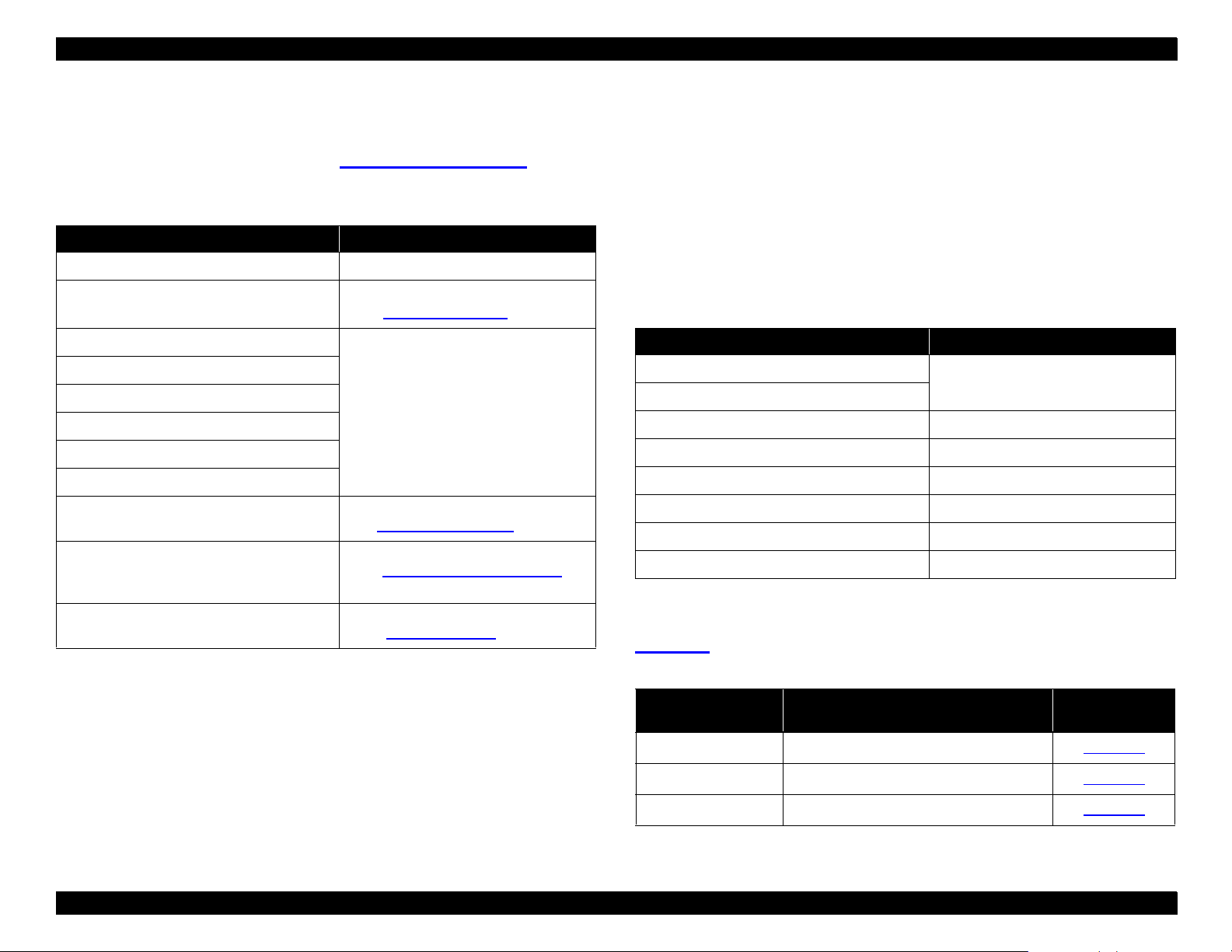
Guide to Using This Manual
Before servicing the EPSON Stylus Pro 9000, read the precautions on
CHAPTER 1. Printer Basics
Refer to this chapter for details on control panel operation.
CHAPTER 2. Technical Overview
Read this chapter if you want to know more about how the major systems of this
printer work.
CHAPTER 3. Troubleshooting
Use this chapter to troubleshoot typical printer problems.
CHAPTER 4. Disassembly and Assembly
Follow these step-by-step instructions to disassemble and assemble the printer.
Refer to the “Maintenance” section of this chapter when you need to replace the
Waste Ink Pads and other consumable parts.
CHAPTER 5. Adjustments
When you remove or replace parts, read the beginning of this chapter to find out
which adjustments are required and how to perform them.
CHAPTER 6. Maintenance
Follow these routine inspection and maintenance pro ced ures each time you
service the printer.
page 5
. Then turn to one of these chapters:
CHAPTER 7 Appendix
Provides the following additional informati on for reference :
• Setup instru ctions
• Detailed product specifications
• Parts list
• Exploded di agrams
• Electrical circuit boards schematics
Page 3

COPYRIGHT NOTICE
All rights reserved. No part of this publication may be reproduced, stored in a retrieval system, or transmitted in any form or by any means, electronic, mechanical,
photocopying, recording, or otherwise, without the written permission of Epson America, Inc. No patent liability is assumed with respect to use of the information
contained herein. Neither is any liability assumed for damages resulting from the use of the information contained herein. While every precaution has been taken in
the preparation of this book, Epson America, Inc., assumes no responsibility for errors and omissions.
Neither Epson Americ a, Inc ., nor its affilia tes sh all be liable to the purchaser of this product or third partie s for damages, losses, costs, or expenses incurred by
purchaser or third parties as a result of: accident, misuse, or abuse of this product or unauthorized modifications, repairs, or alterations to this product.
Epson America, Inc., shall not be liable against any damages or problems arising from the use of any options or any consumable products other than those
designated as Original EPSON Products or EPSON-Approved Products by Seiko Epson Corporation.
TRADEMARKS
EPSON and ESC/P are registered trademarks and ESC/P 2, EPSON Stylus COLOR 900, and EPSON Sylus COLOR 900N are trademarks of Seiko Epson
Corporation. Epson Connection is a service mark of Epson America, Inc.
General Notice:
any and all rights in those marks.
Copyright © 1999 Epson America, Inc.
20770 Madrona Avenue
Torrance, CA 90509-2842
Other product names used herein are for identification purposes only and may be trademarks of their respective compani es. EPSON disclaims
July 1999
Page 4

FCC COMPLIANCE STATEMENT
g
q
q
FOR AMERICAN USERS
This equipment has been tested and found to comply with the limits for a Class B digital device, pursuant to Part 15 of the FCC Rules. These limits are designed to
provide reasonable protection against harmful interference in a residential installation. This equipment generates, uses, and c an radiate radio frequency energy and,
if not installed and used in accordance with the instructions, may cause harmful interference to radio and television reception. However, there is no guarantee that
interference will not occur in a particular installation. If this equipment does cause interference to radio and television reception, which can be determined by turning
the equipment off and on, the user is encouraged to try to correct the interference by one or more of the following measures:
Reorient or relocate th e receivin
Increase t he separation between the e
Connect the e
Consult th e dealer or an ex perience d radio/TV t ec hnician fo r help.
WARNING
The connection of a non-shielded equipment interface cable to this equipment will invalidate the FCC Certification of this device and may cause interference levels
that exceed the limits established by the FCC for this equipment. It is the responsibility of the user to obtain and use a shielded equipment interface cable with this
device. If this equipment has more than one interface connector, do not leave cables connected to unused interfaces.
Changes or modifications not expressly approved by the manufacturer could void the user's authority to operate the printer.
FOR CANADIAN USERS
This Class B digital apparatus meets all requirements of the Canadian Interference-Causing Equipment Regulations.
Cet appareil numérique de la classe B respecte toutes les exigences du Règlement sur le materiel brouilleur du Canada.
uipment int o an outlet on a circuit diff erent from that to which t he receiver is co nnected .
antenna.
uipment and receiver.
Page 5

PRECAUTIONS
g
y
Precautionary notes throughout the text are categorized with respect to: (1) personal injury and (2) damage to equipment.
W ARNING
CAUTION
Always observe the precautions listed below when performing repair and maintenance procedures.
Signals a precaution which, if ignored, could result in serious or fatal personal injury. Great caution should be exercised in performing a procedure
preceded by a WARNING.
Signals a precaution which, if ignored, could result in damage to equipment.
WARNING
1. Always disconnect the product from both the power source and the host computer before performing any maintenance or repair procedure.
2. No work sh ould be perfo rm ed on the un it by persons u nf am iliar with bas ic s af ety measure s dic t at ed for all elect ronics technicians in th eir line of
work.
3. In performin
must be co nnected, use extreme ca ut ion in working on the pow er s upply and other electronic c om ponents.
testing describe d in this manu al, do not connec t t he unit to a pow er s ource until instructe d t o do so. When th e power supply cable
CAUTION
1. Repairs o n EPSON pr oducts should be perfo m ed only by an EPSO N -c ertified repair technic ian.
2. Make certain that the source voltage is the same as the rated voltage listed on the serial number/rating plate. If the EPSON product has a primary
AC rating different from the available power source, do not connect it to the power source.
3. Always verify that the EPSON prod uc t has been disconnected f rom t he power source bef ore removing or replacing printed circuit boards or
individual chips.
4. To protect se ns it iv e microproc essors an d ot he circuitr
components.
5. Replace malfunctioning components only with those components recommended by the manufacturer; introduct ion of second- sour ce ICs or other
nonappr ov ed components may damage the product and void any applicable EPSON w arranty.
, use static discharge equipment, such as anti-static wrist straps, when accessing internal
Page 6

EPSON Stylus Pro 9000 Revision A
Contents
1 Printer Basics
Features ...................................................................................................... 11
Control Panel Operations ......................................................................... 12
Control Panel Buttons ............................................................................ 12
Operation in Normal Mode .................................. .......... ....... .. .......... .. 12
Operation at Power On ....................................................................... 13
SelecType Mode .................................................................................... 13
Control Panel Operation in SelecType Mode ..................................... 13
Main Menu Options in SelecType Mode ............................................ 13
Printer Setting Menu........................................................................ 14
Test Print Menu............................................................................... 15
Printer Status Menu......................................................................... 15
Paper Configuration Menu. .............................................................. 16
Cutter Replace Menu....................................................................... 16
Head Alignment Menu..................................................................... 16
Service-Related Modes .......................................................................... 17
Maintenance Mode . ............................................................................ 17
Maintenance Mode 2 .......................................................................... 17
LED Indicators and Error Messages ........................................................ 18
LED Indicators ........................................................................................ 18
LCD Display ........................................................................................... 19
Options and Consumables ....................................................................... 20
2 Technical Overview
Location of Com ponents .......................................................................... 22
Carriage Mechanism ....................................................................... 22
Paper Feed Mechanism .................................................................. 22
Ink System ....................................................................................... 23
Circuit Boards.................................................................................. 23
Operation ................................................................................................... 24
Carriage Mechanism .............................................................................. 24
Carriage (CR) Guide Rail ................................................................ 24
Platen Gap (PG) Mechanism........................................................... 24
Paper Width Sensor........................................................................ 25
Carriage Motor and Position Control............................................... 26
Cutter Mechanism .................................................... .......... .. ....... .... 27
Printheads ....................................................................................... 27
Paper Feed Mechanism ......................................................................... 28
Paper Feed Motor and Rollers . . ...................................................... 28
Paper Feed Sensors ....................................................................... 29
Paper Suction Fan........................................................................... 30
Paper Width Determination (Left and Right edge Detection) . ......... 31
Paper size Determination (Detection of Top edge) ......................... 32
Paper Loading Errors ...................................................................... 33
Carriage Lock Mechanism ..................................................................... 33
Ink Supply Mechanism ........................................................................... 34
Ink-Related Sensors........................................................................ 35
Cover Open Sensor ............................................................................... 36
Control Circuit ........................................................................................ 37
3 Troubleshooting
Overview .................................................................................................... 39
Troubleshooting Usin g LCD Error Messa ges ......................................... 39
LCD Error Messages .................................. ....... ....... ....... ..... ....... ....... .... 40
Errors that require a service technician .................................................. 41
General Errors ........................................................................................ 45
Ink Low............................................................................................ 45
Paper Out........................................................................................ 45
Load xxx Paper ............................................................................... 45
Load Paper...................................................................................... 45
Paper Jam....................................................................................... 46
Cover Open..................................................................................... 46
6
Page 7

EPSON Stylus Pro 9000 Revision A
Paper Not Cut . ................................................................................. 46
Paper Not Straight. .......................................................................... 46
Reload Paper................................................................................... 47
Push Lever Down............................................................................ 47
Compartment Open......................................................................... 47
Ink Out............................................................................................. 48
No Ink Cartridge .............................................................................. 48
Remove Paper................................................................................. 48
Option I/F Error................................................................................ 48
Print Quality Troubleshooting .................................................................. 49
Missing Dots or Lines...................................................................... 49
No Ink Output from One or Both Printheads.................................... 50
Uneven Printing or Poor Resolution................................................ 50
Smudged or Marred Printout (Front) ............................................... 51
Smudged or Marred Printout (Reverse side)................................... 51
White or Black Banding ................................................................... 51
Connector-Related Errors ......................................................................... 52
4 Disassembly & Assembly
Overview ..................................................................................................... 55
Precautions ............................................................................................ 55
Tools ....................................................................................................... 56
Screw List ............................................................................................... 56
Order of Disassembly ............................................................................. 57
Housing Parts ......................................................................................... 58
Housing Removal ...................................................................................... 58
Maintenance Cover Removal .......................................................... 58
Top Cover Removal......................................................................... 59
Left and Right Side Cover Removal................................................ 60
Front Cover Removal...................................................................... 61
Roll Cover Removal......................................................................... 62
Lower Paper Guide Removal ................................................... ....... 63
Upper Paper Guide Removal ................................................... ....... 64
Circuit Board Removal .............................................................................. 65
Power Supply Board Removal......................................................... 65
Main Board Removal....................................................................... 66
Maintenance Procedures .......................................................................... 67
Replacing the Waste Ink Pads........................................................ 67
Maintenance Assembly Removal & Disassembly........................... 69
Printer Mechanism Disassembly ............................................................. 71
Replacing the Printheads................................................................ 71
Removing the Carriage Motor Assembly......................................... 75
Removing the PF Motor Assembly.................................................. 76
Removing the Platen Gap Adjustment motor.................................. 78
Removing the Platen Gap Home Position Sensor........................... 78
Removing the Cover open Sensors................................................. 79
Removing the Paper Thickness Sensor.......................................... 80
Removing the Rear Paper Sensor................................................... 80
Removing the Front Paper Sensor.................................................. 81
Removing the Paper Release Sensor............................................. 81
Removing the Carriage Home Position Sensor and Encoder ......... 82
Ink Holder Disassembly ............................................................................ 84
Removing the I/C Holder Assembly ....................................................... 84
Disassembling the I/C Holder ................................................................. 91
Removing the Ink Tubes ........................................................................... 92
Preparation...................................................................................... 92
Removing the Ink Pipe Covers........................................................ 92
Separating the ink pipes and ink tubes ........................................... 92
Removing the CR circuit board........................................................ 93
Disconnecting the ink dampers....................................................... 93
Removing the cable connection plate.............................................. 94
Ink Tubing Reassembly .......................................................................... 95
Installing the new cable connec t ion plate........................................ 95
Positioning the tube guides and FFCs............................................. 95
Connecting the ink tubes to the ink pipes........................................ 96
Securing the the ink tubes and ink pipes......................................... 96
Securing the tube guides on the CR side........................................ 96
Checking the ink tubes.................................................................... 97
Attaching the CR circuit board......................................................... 97
Connecting the carriage FFCs......................................................... 97
Connecting the ink tubes and dampers. .......................................... 98
Confirming the tube guide assembly position.................................. 99
Connecting the carriage FFCs to the relay circuit board. .............. 100
Resetting the printer...................................................................... 100
7
Page 8

EPSON Stylus Pro 9000 Revision A
5 Adjustments
Overview ......... ....... ..................... ...................... ..................... ................... 102
Precautio n s ............................ ...................... ..................... ................... 102
Adjustment Tools .................................................................................. 102
Required Adjustments ......................................................... ....... .......... 103
ROM Backup and Updating ........... ..................... ...................... .............. 105
Requirements for Backup.............................................................. 105
Backup Procedure......................................................................... 105
Download Proce d ure............ ............................ ...................... ....... 106
Possible Errors During Backup or Downloading............................ 106
Firmware Update ... ............................................................................... 106
Updating From a PC...................................................................... 106
Updating From a Memory Card..................................................... 107
Self-Diagnostics ........................... ..................... ..................... ................. 107
Using the Self-Diagnostic Mode . .......................................................... 108
Self-Diagnostic Menus ......................................................................... 109
Test Menu ............................................................................................ 110
Version................................... ...................... ............................ ..... 111
Control Panel ................................................................................. 111
Sensors................ ..................... ..................... ..................... .......... 112
Encoder ......................................................................................... 113
Fan ................................ ..................... ...................... ..................... 113
Elec. (Maintenance Records) ........................................................ 113
Adjustment Menu ................................................................................. 115
Cap Position Adjustment............................................................... 116
Check Skew.......................... ..................... ...................... .............. 117
Input Rank (Printhead ID) Adjustment........................................... 117
Check Nozzle....................... ..................... ...................... .............. 118
B Head Slant/C Head Slant Adjustment (Head Angle).................. 119
BC Head Slant Adjustment (Head Height) .................................... 120
Bi-D Adjus tmen t............... ...................... ..................... ................... 121
Head LR Adjustment (Head Gap Timing).... .................................. 123
Flush Point Right and Left Adjustment.......................................... 124
Feed Adjustmen t............. ............................. ..................... ............ 124
Top & Bottom (Margin) Adjustment............................................... 125
Rear Sensor Position Adjustment.................................................. 126
Test Print....................................................................................... 127
Clean Head (Drain Ink).................................................................. 127
Counter Clear ................................................................................ 128
Cleaning menu ...................... ....... .. ....... .......... ....... .. ....... .......... .. ....... .. 128
Print menu ............................................................................................ 128
Parameter menu .................................................... .. ....... .......... .. ....... .. 129
Initialize......................................................................................... 129
Update........................................................................................... 129
Mechanical Adjustments ........................................................................ 130
Carriage Cover Height Adjustment..................................... .. ....... .. 130
Cutter Position Adjustment............................................................ 131
Carriage Belt Tension Adjustment................................................. 132
PF Belt Tension Adjustment.......................................................... 132
Platen Gap Gear Backlash Adjustment......................................... 133
I/H Lever Position Adjustment ....................................................... 133
Paper Thickness Sensor Adjustment............................................ 134
Cover Open Sensor Assembly (Right and left).............................. 135
Sensor Trimmer Adjustment.......................................................... 136
6 Maintenance
Overview .................................................................................................. 138
Physical Inspection and Cleaning ......................................................... 138
Lubrication ............................................................................................... 139
Checking and Clearing Counters ........................................................... 139
Checking Maintenance Counters ......................................................... 140
Clearing Maintenance Counters ........................................................... 140
Service Error Code s and Rep laceabl e Part s ........................................ 143
The Difference Between a ‘Maintenance Call’ and a ‘Service Call’ ...... 143
Ink Cartridge Replacement ..................................................................... 144
Cutter Blade Replacement ...................................................................... 144
8
Page 9

EPSON Stylus Pro 9000 Revision A
7 Appendix
Unpacking and Transporting the Printer .......................................... ..... 146
The Packagin g ......... ..................... ...................... ............................ ..... 146
Before Opening the Large & Medium boxes................................. 146
Contents of the Packaging ................................................................... 146
Medium-size b ox.......................................... ..................... ............ 146
Large box....................................................................................... 147
Unpacking and Assembly ..................................................................... 147
From unpacking to assembling the Stand..................................... 147
Assembling the Printer body.......................................................... 151
Repacking and Transporting the Printer ............................................... 155
Before Shipping............................................................................. 155
After Shi ppi n g....... .............. ..................... ............................ .......... 155
Specifications ............ ....... ............................ ...................... ..................... 156
Mechanical .................................... ...................... ..................... ............ 156
Safety Appr ov a ls ................................ ..................... ...................... ....... 157
CE Marking ...... ....... ..................... ..................... ...................... .............. 157
Electrical ............................. ..................... ..................... ...................... .. 158
Environmen ta l ...................... ..................... ...................... ..................... 158
Ink Cartridge ......................................................................................... 158
Controll e r .............................. ..................... ...................... ..................... 159
Cutter .................................................................................................... 159
Paper .................................................................................................... 160
Paper Release Lever ............................................................................ 162
Interface ........................ ..................... ..................... ...................... ....... 162
Paralle l i nt e r fa ce .................... ..................... ..................... ................. 164
Nibble Mode ..................... ..................... ...................... ..................... 166
ECP Mode ........................................................................................ 166
Type-B Interface (Optional) .............................................................. 168
Interface se le ction ............ .............. ..................... ...................... ....... 168
Initialization ........... .............. ............................. ..................... ................... 169
Jumper and DIP Switch Settings ............ ....... ..................... ................... 170
Connector Summary ...... ....... ..................... ............................ ................. 171
Parts List ... ...................... ..................... ..................... ..................... .......... 173
Exploded D ia gram s ..... ....... ...................... ..................... .......................... 179
Main Board Component Layout .................. ...................... ..................... 194
Circuit Diagrams ......................................... ..................... ...................... .. 196
9
Page 10
PRINTER BASICS
Page 11
EPSON Stylus Pro 9000
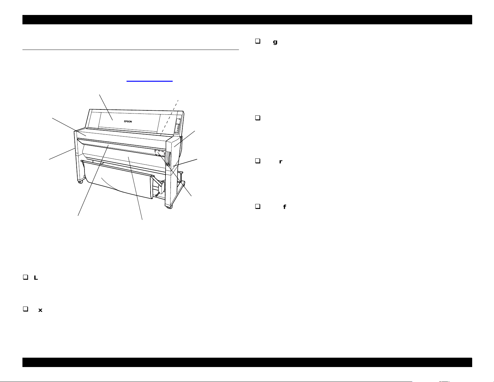
1.1 Features
The EPSON Stylus Pro 9000 is an ultra-wide, 6-color ink jet printer with
professional color o ut put. It provid es t he c olor printin g f eatures listed
below. (For addition al details, see
Roll Cover
Top Cover
Specifications
on page 156.)
Upper P aper Guide
(behind Top Cov er)
Right Side
Cover
High-speed printing
64 nozz les per color
RISC-CPU and high-speed color raster ASIC quickly process
detailed print data
approx. 10 minutes (360
approx. 30 minutes (720
approx. 55 minutes (1440
Low operating costs
× 360 dpi/speed) on A0/normal paper
× 720 dpi/quality) on A0/glossy paper
× 720 dpi/superfine) on A0/glossy paper
6 separate ink cartridges so only the empty ink cartridge is replaced
Auto Rotate feature saves paper by automatically rotating an image
if the widt h is s horter than th e height
Left Side
Cover
Front Cover
Lower Paper Gui de
Figure 1-1. Exterior View of the EPSON Stylus Pro 9000
Large printing
Up to B0-wide paper (44 inches [1,118 mm]), including print
registration marks
Excellent photo-quality printing
1440 (H)
× 720 (V) dpi co m bined with EPSON’s M ic rodot printing
Right Joint
Cover
Main tenance
Cover
Alternative interface compatibility
IEEE-1284 bidirectional parallel interface (supports ECP mode)
Macintosh serial int erface (approximat ely 1. 8 Mbps)
Type-B ex pansion slot f or an optiona l int erface
User friendly
2 roll hold ers f or easily swit c hing between paper types
Standard roll paper cutter
Optional roll paper take-up reel for automatically winding up your
long prin t outs
Printer Basics 11
Page 12
EPSON Stylus Pro 9000
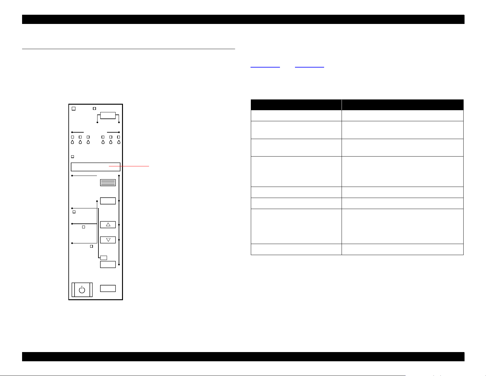
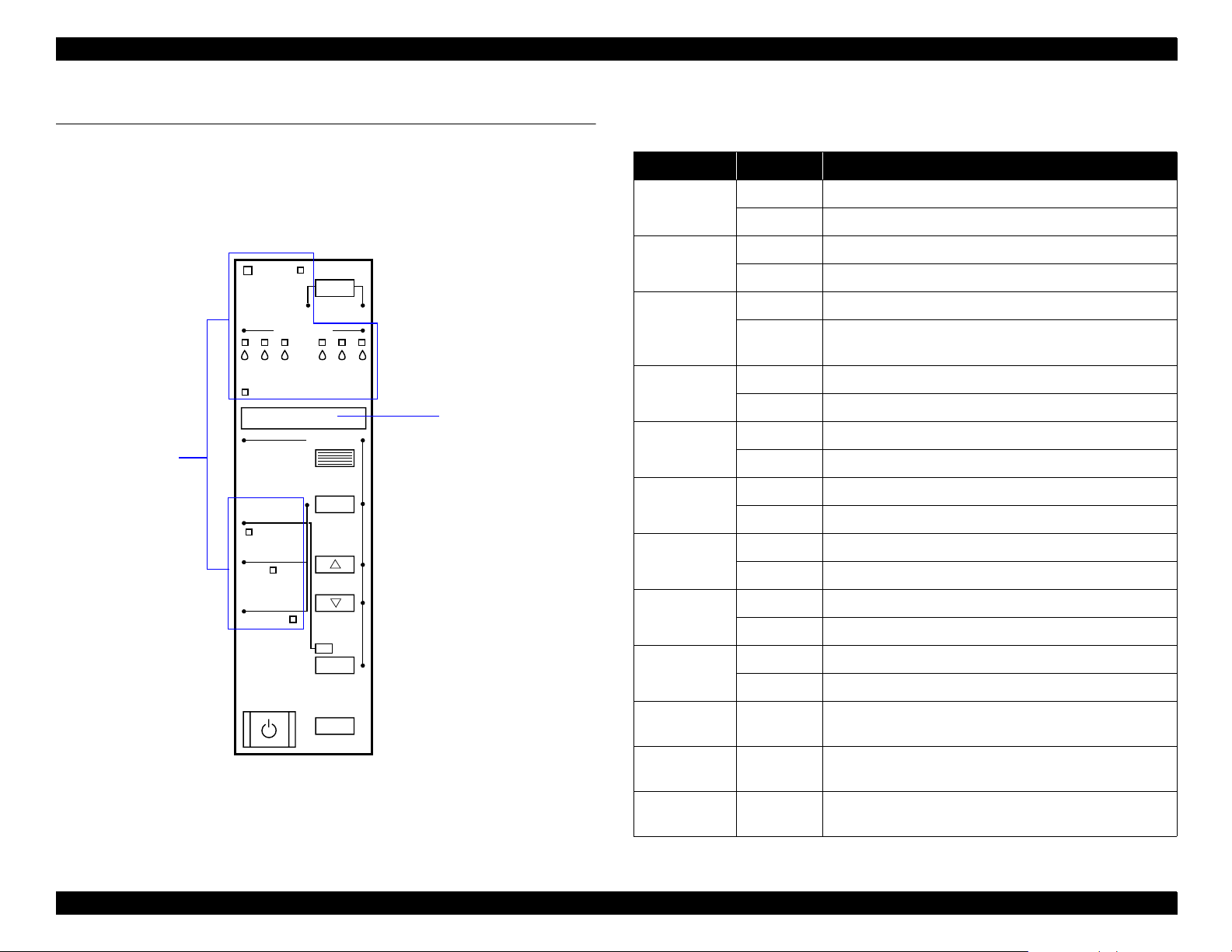
1.2 Control Panel Operations
The EPSON Stylus Pro 9000 co nt rol panel dis plays status and error
messages , and the lights indicate wh en a problem oc c urs or if any ink
cartridge is low or runs out. This section provides inf ormatio n on the
control panel buttons, LEDs, and liquid crystal display (LCD).
Ink Out
Paper Source
Pause
Reset
3 sec.
SelecType
Item
+
Paper Feed
_
Cut /Eject
Enter
Cleaning
3 sec.
LCD Display
Operate
KC LCMLMY
Paper Out
Roll
Auto Cut
Roll
Cutter Off
Sheet
Power
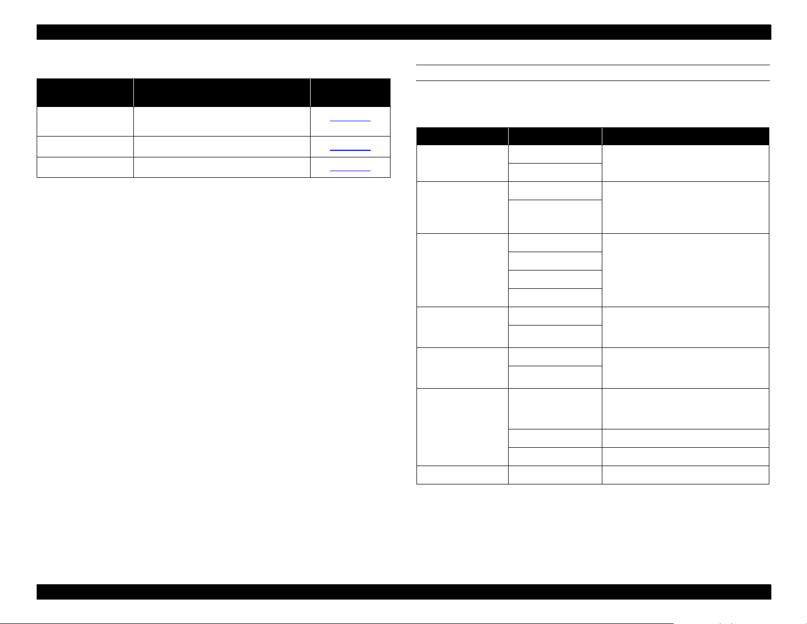
1.2.1 Control Panel Buttons
Pressing a control panel button executes the functions listed in
and
Table 1-1
Table 1-2
1.2.1.1 Operation in Normal Mode
Table 1-1. Operation in Normal Mode
Button (Second function) Function
Power Power ON and OFF
Pause (Reset) Switches between onl ine and offline.
SelecType Enters SelecType mode (when printer is in
Cut/Eject (Enter)*
Paper Feed
Paper Feed
Paper Source (Item) Selects paper source:
Cleaning Cleans both heads if pressed for 3 seconds
* Int errupts the ink-drying time, if taking place.
** 1.27 cm/second paper feed for 2 seconds after key is pressed.
7.62 cm/second paper feed if pressed for over 2 seconds.
Maximum feed of 20 cm when the button is pressed once.
***1.27 cm/second paper feed for 2 seconds after key is pressed.
7.62 cm/second paper feed if pressed for over 2 seconds.
U
D
.
Resets the printer i f pressed for 3 seconds.
Standby)
• Cuts and ejects paper if Roll Aut o Cut is
selected
• Ejects paper if Roll Cutter Off or Sheet is
selected
Feeds paper backward**
Feeds paper forward***
•Roll Auto Cut
• Roll Cutter Off
• Sheet
Figure 1-2. EPSON Stylus Pro 9000 Control Panel
Printer Basics 12
Page 13
EPSON Stylus Pro 9000
1.2.1.2 Operation at Power On
Pressing th es e buttons a t po w er on puts the printer in one of th e
following service-related modes. See
Service-Related Modes
page 17 for d et ails .
Table 1-2. Operation at Power On
Button (Second function) Function
Power —
Pause (Reset) Maintenance Mode
See
Maintenance Mode
SelecType
Cut/Eject (Enter)
Paper Feed
Paper Feed
Paper Source (Item)
Cleaning
Paper Source, Paper Feed
Paper Source, Cut/Eject, Cleaning Firmware Update Mode
Paper Feed
U
D
, Cut/Eject Maintenance Mode 2
D
See
Maintenance Mode 2
See
ROM Backup and Updating
, Cut/Eject, Cleaning Self-Diagnostic Mode
D
See
Self-Diagnostics
—
page 105
on
on page 17
on page 17
on page 107
on
1.2.2 SelecT ype Mode
The SelecType menus allows y ou to configu re printer set t ings and
perform c ert ain maintenance op erations fro m th e c ontrol pane l. To
access these menus, press th e SelecType button while the printer is not
printing. The printer enters the SelecType mode and cannot print.
1.2.2.1 Control Panel Operation in SelecType Mode
The con tr ol panel buttons have th e f ollowing func t ions in this mode:
Table 1-3. Operation in SelecType Mode
Button (Second function) Function
Power
Pause (Reset)
SelecType Selects menu
Cut/Eject (Enter) Confirms and saves value
Paper Feed
Paper Feed
Paper Source (Item) Selects item within a menu
Cleaning —
U
D
Increases a value
Dec re ases a value
1.2.2.2 Main Menu Options in SelecType Mode
Table 1-4
lists the menus and where to find additional in fo rm ation.
—
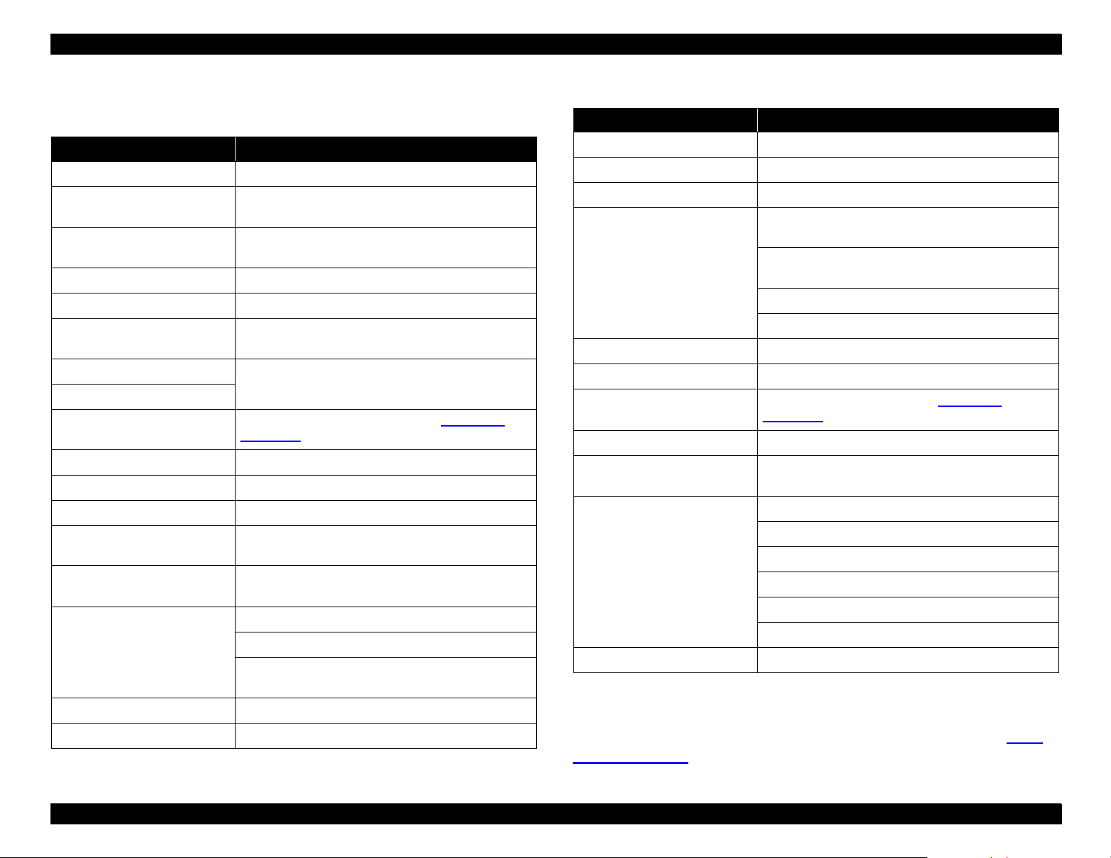
Table 1-4. SelecType Menus
Menu Description For more
information
Printer Setting Configure the printer
Test Print Print a nozzle check or status check
Printer Status Check ink levels and component life
page 14
page 15
page 15
Printer Basics 13
Page 14
EPSON Stylus Pro 9000
Table 1-4. SelecType Menus (continued)
Menu Description For more
Paper Configuration Register pape r thi ckne ss and dr ying t ime,
and select registered configurations
Cutter Replacement Replace the pap er cut ter blade
Head Alignment Align the printhe ad
information
page 16
page 16
page 16
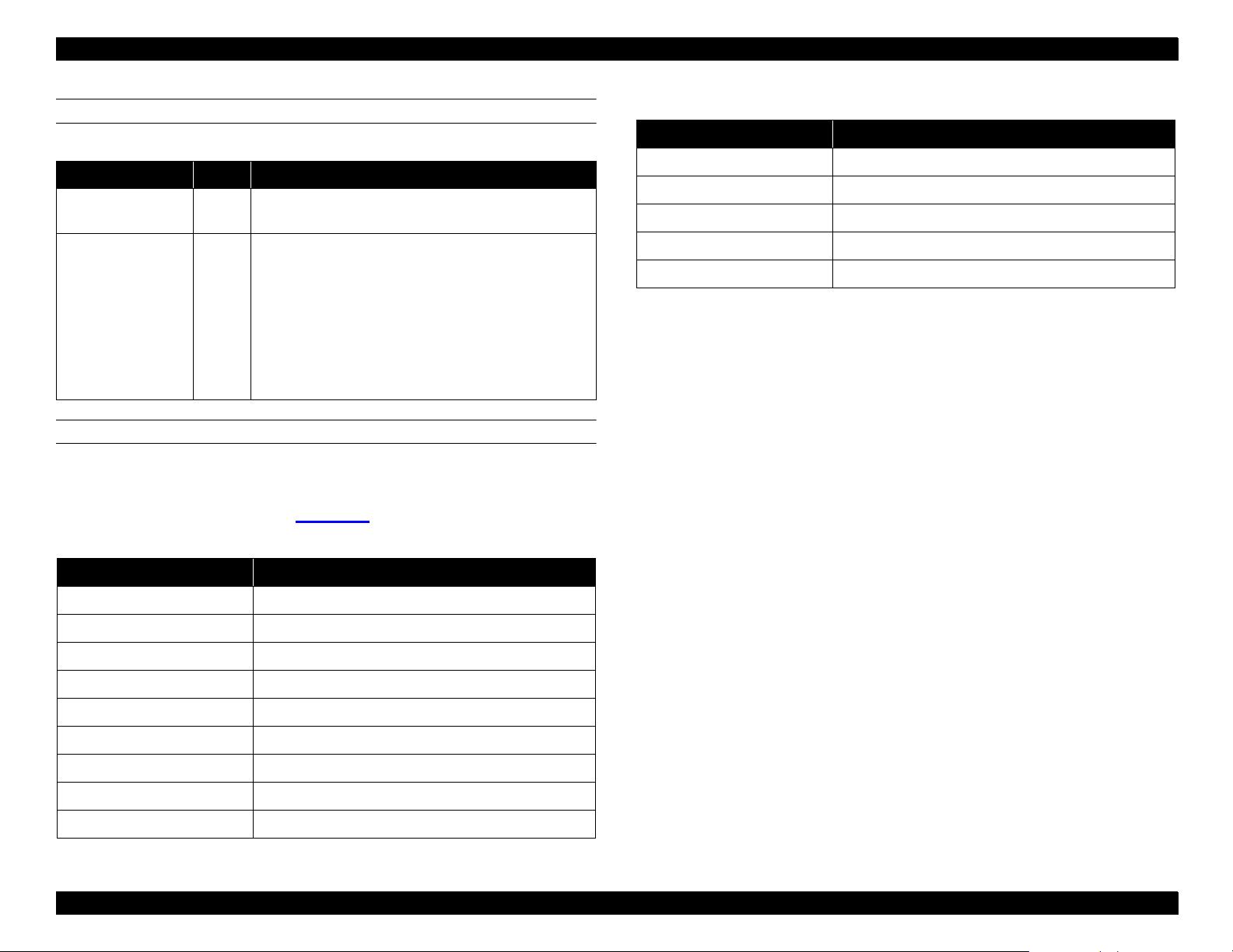
PRINTER SETTING MENU
The bold it em is the default setting.
Table 1-5. Printer Setting Menu
Message Item Explanation
PLATEN GAP
PAGE LINE
INTERFACE
PARA. I/F
CODE PAGE
AUTO
THICK
ON
OFF
AUTO
PARALLEL
MAC
OPTION
COMPAT*
ECP
PC437
PC850
Adjusts the platen gap. Normally leave
set to AUTO.
When AUTO CUT OFF is selected on
the control panel, this setting
determines whether a li ne for ma nual
cutting is printed
Determines which interface the print er
checks for data. AUTO cont inuously
checks all interfaces and is good for
normal use. MA C is the serial interface.
Determines the data t ran sfer r ate when
using this interface. Normally leave set
to COMPAT*.
Character code setting. PC437 is for
expanded graphics. PC850 is for multilingual.
ROLL MARG
INIT. PANEL EXEC. Initialize control panel setup values
* The printed image is t he sam e size as the printed image using the 0.12 inch (3 mm)
setting. However , t he printer adds 0.47 inch ( 12 mm) of paper clearance (for a total
margin of 0.59 inch [15 mm] ) to t he top and bottom edges to make paper feeding
more stable and to preven t the paper from rubbing the printheads.
T/B15MM*
15MM All margins are 0.59 in. (15 m m).
3MM All margins are 0.12 in. (3 mm).
Top and bottom margins are 0. 59 in.
(15 mm). The left and right margins ar e
0.12 in. (3 mm).
Printer Basics 14
Page 15
EPSON Stylus Pro 9000
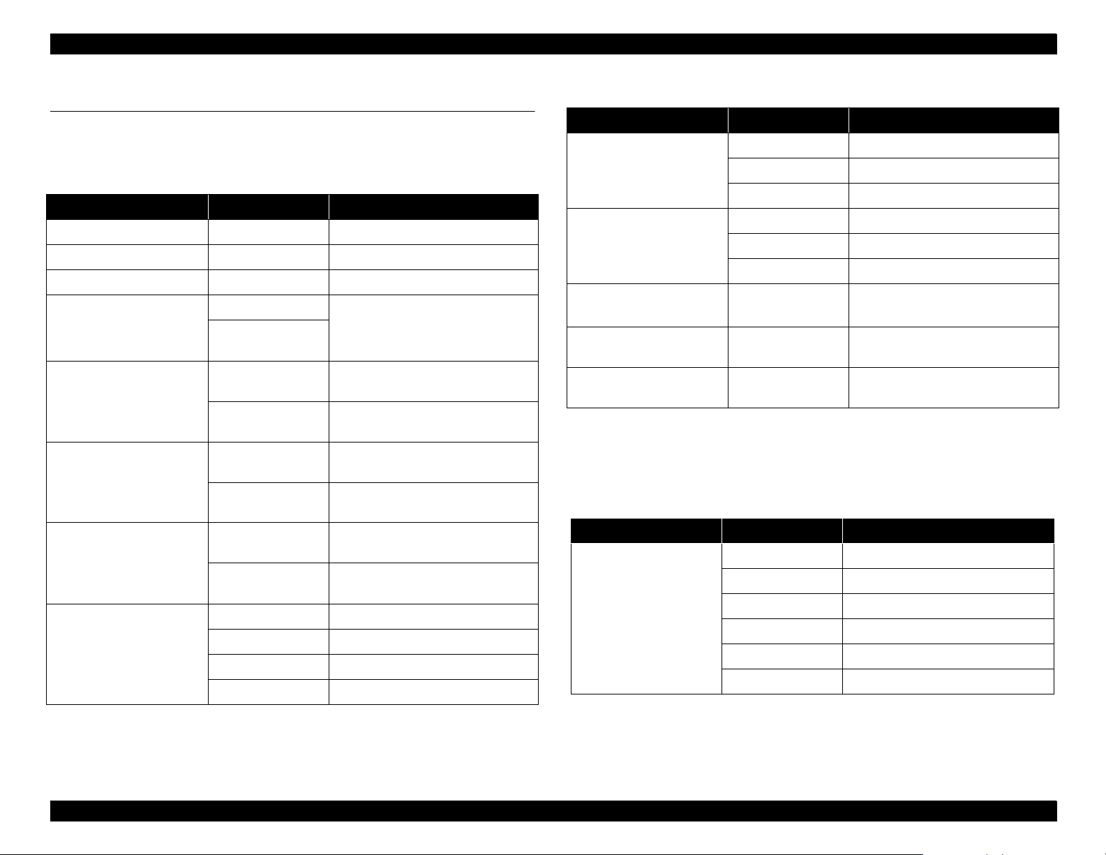
TEST PRINT MENU
Table 1-6. Test Print Menu
Message Item Explanation
NOZZLE CHECK PRINT Check the printo ut. Any missing lines mean the
nozzle(s) ar e clogged.
STATUS CHECK PRINT Prints the amount of ink lef t or the component life as
follows:
• E*****F = full (or full life remaining)
• E ****F = ¾ full (or ¾ life remaining)
• E ***F = ½ full (or ½ life remaining)
• E **F = ¼ full (or ¼ life re maining)
• E *F = nearly empty (or service life near end)
• E F = empty (or service life ended)
PRINTER STATUS MENU
Use this menu to view the printer status on the contr ol panel display
without printing a sta tu s ch eck. While in this m enu, press th e I tem
button to view the messages in Table 1-7
.
Table 1-7. Printer Status Menu
Table 1-7. Printer Status Menu (continued)
Message Explanation
WASTE INK Ink pad maintenance information
CR MOTOR Carriage motor maintenance information
PF MOTOR Paper feed motor mainten ance information
HEAD UNIT Printhead maintenance information
CLEANER Maintenance information
Contin ue pressing t he Item button to display the am ount remaining for
each of the 6 inks or se rv ic e lif e remainin g f or t he part. The indicator
reads as fo llows:
E*****F = full (or full life remaining)
E **** F = ¾ full (or ¾ lif e remaining )
E ***F = ½ full (or ½ life remaining)
E **F = ¼ full (or ¼ life remaining)
E *F = nearly empty (or service life ne ar end)
E F = empty (or se rv ic e lif e ended)
Message Explanation
VERSION <number> Shows the firmware version
INK LEFT-C Amount of cyan ink remaining
INK LEFT-M Amount of magenta ink remaining
INK LEFT-LC Amount of light cyan ink remaining
INK LEFT-LM Amount of light magen ta ink remaining
INK LEFT-Y Amount of yellow in k remaining
INK LEFT-K Amount of black ink r em aining
CUTTER LIFE Useful life of the cutter remaining
TOTAL PRINTS Total num ber of printed documents
Printer Basics 15
Page 16
EPSON Stylus Pro 9000
PAPER CONFIGURATION MENU
The bold ite m is th e default sett ing.
Table 1-8. Paper Configuration Menu
Message Item Explanation
PAPER NUMBER
THICK. PAT PRINT Prints a pattern t o detec t the paper
PAPER THICK 1 If PAPER NUMBER is set to STD, the
DRYING TIME 0MIN De termines the length of time th e pri nter
STD*
1 Select the appropriate number for thick
Select STD for Epson specia l paper
paper. Use the
registered number up to 4.
thickness. If PAPER NUMBER is set to
STD, the message does not appear.
message does not app ear. Use the
select the reg istered number up to 17.
allows the ink to dry. When printing on roll
paper, the print er will wai t the specif ied ti me
after printing. Use the
registered number up to 30MIN.
or − to select the
+
or − to select the
+
or − to
+
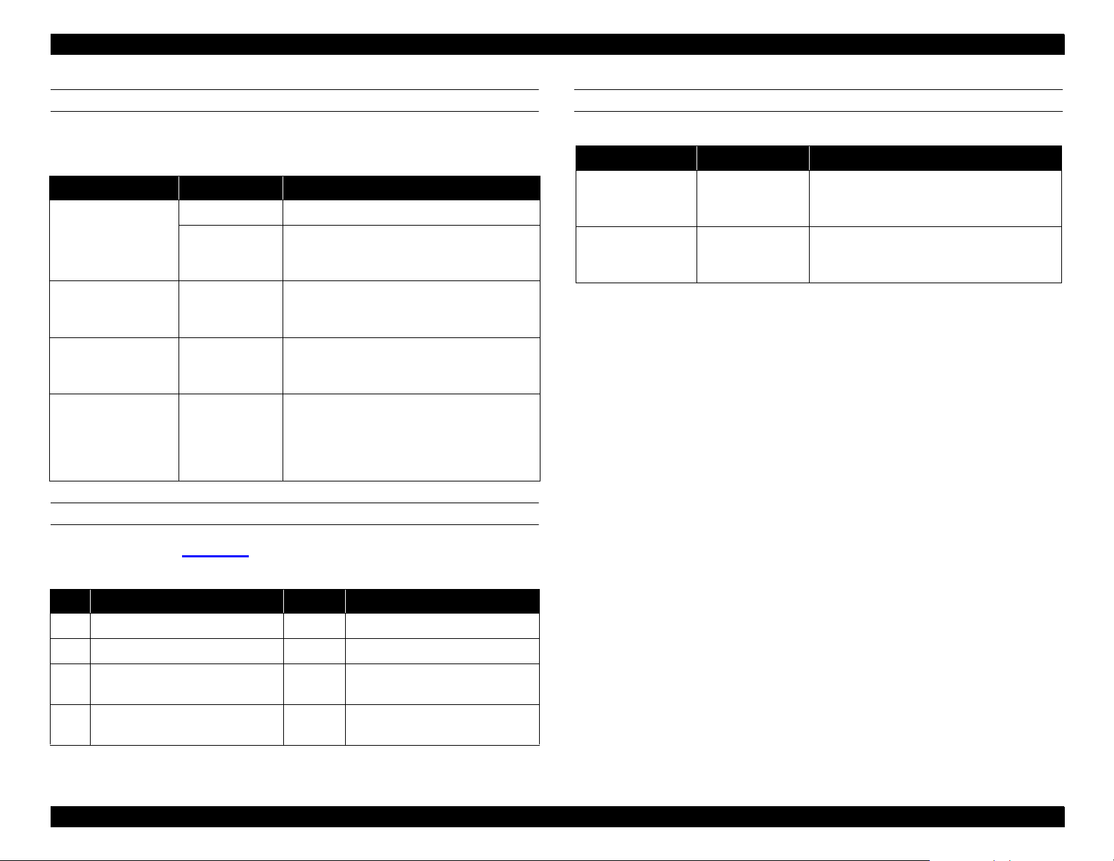
HEAD ALIGNMENT MENU
Table 1-10. Head Alignment Menu
Messages Item Explanation
ADJUST. PATT
PAPER THICK STD Leave on STD for EPSON paper. For other
ALL
Prints a full series of patterns. To print a
single pattern, use the
registered pattern appears.
media, use the
thickness in 0.1-m m increments.
+
and − until the
+
and − to select the
CUTTER REPLACE MENU
Follow the order in Table 1-9
to replace the cutter.
Table 1-9. C u tter R eplacement Menu
Step Message Item Explanation
1 CUT. REPLACE EXEC. Prepare a replacement cutter
2 OPEN LOWER COVER — Open the front cover
3 REPLACE CUTTER — Remove the old cutter and instal l
a new one
4 CLOSER LOWER COVER — Close the front cover. READY
appears on the display.
Printer Basics 16
Page 17
EPSON Stylus Pro 9000
1.2.3 Service-Related Modes
Press and hold down the buttons li sted in
enter one of t hes e service- related modes:
Maintenance Mode
Lets you print a hex dum p or change th e language us ed for LCD
display messages . S ee
Maintenance Mode 2
Table 1-11
Lets you clear maintenance counters after replacing consumable
parts. See
Self-Diagnostic Mode
Table 1-12
on this pag e.
Lets you adjust printer settings, check and reset certain counters,
make test prints, a n d cle an th e pri nt head. S ee
page 107.
Firmware Update Mode
Lets you update the printer’s firmw are after replacing the Main
Board. See
CAUTIO N
ROM Backup and Updating
The operations described in this section a re for s ervic e
and support only. Avoid sharing this information with
the end us er .
Table 1-2
on this page.
Self-Diagnostics
on page 105.
at power on to
on
1.2.3.1 Maintenance Mode
Press the
Message Menu Item Explanation
HEX DUMP PRINT Pr int data printed in
LANGUAGE ENGLISH, PORTUGUESE, SPANISH,
Pause
button while turning on the printer.
Table 1-11. Maintenance Mode Menu
GERMAN, ITALIAN, FRENCH
hexadecimal form
Determines language used
for LCD display messages
1.2.3.2 Maintenance Mode 2
Press the
Paper Source, Cut/Eject,
turning on the printer.
Table 1-12. Maintenance Mode 2 Menu
Message Menu Item Explanation
INIT. ALL EXEC. Initializes NVRAM, Timer, life counters, and
mechanical coun ters
INIT. NVRAM EXEC. Initializes NVRAM
INIT. TIMER EXEC. Initializes timer
INIT CR MOTOR EXEC. Initialize s CR motor (after r eplacing ink tubes)
INIT. PF MOTOR EXEC. Initializes PF motor
Paper Feed
and
D buttons while
INIT. HEAD UNIT EXEC. Initializes head unit
NOTE: In Main te nanc e M ode an d Main te nanc e M ode 2, pre ss t he
Paper Source button to select a menu item, and press
Enter save a setting.
INIT CLEANING
UNIT
INIT. TOTAL
PRINTING
INIT. INK EXEC. Initializes ink counter
INIT. WASTE INK EXEC. Initializes waste ink counter
DETECT INK LABEL ON
EXEC. Initializes cleaning unit
EXEC. Initializes total print counter
Determines whether the Ink ID sensor checks
OFF
the ink ID label on the ink cartridge.
Printer Basics 17
Page 18
EPSON Stylus Pro 9000
1.3 LED Indicators and Error Messages
The printe r dis plays stat us m es s ages and e rror codes us ing its LED
indicators and LCD panel. Interpret these messages using the tables on
the following pages .
Ink Out
Paper Source
Pause
Reset
3 sec.
SelecType
Item
+
Paper Feed
_
Cut /Eject
Enter
Cleaning
3 sec.
LCD Display
LED Indicators
Operate
KC LCMLMY
Paper Out
Roll
Auto Cut
Roll
Cutter Off
Sheet
Power
1.3.1 LED Indicators
Table 1-13. LED Indicators
LED Status Explanation
Operate On Power on
Flashing Receiving data or perfor m ing power-down sequence
Paper Out On No paper loaded
Flashing Paper jam
Pause On Printer ready
Flashing Performing head cleaning. Printer is in ink- drying
phase. Performing ink- charging operation.
Ink Out Y On Ink out (also occurs if no or wrong cartridge is installed)
Flashing Ink low
Ink Out LM O n Ink out (also occurs if no or wrong cartridge is installed)
Flashing Ink low
Ink Out LC On Ink out (also occurs if no or wrong cartridge is installed)
Flashing Ink low
Ink Out M On Ink out (also occurs if no or wrong cartridge is installed)
Flashing Ink low
Ink Out C O n Ink out (also occurs if no or wrong cartridge is installed)
Flashing Ink low
Ink Out K On Ink out (also occurs if no or wrong cartridge is installed)
Flashing Ink low
Paper Source
(Auto C u t)
On Roll paper will automa ti ca ll y b e cut
Paper Type
(Cut Off)
On Roll paper will not be cut (sel ect th is sett ing when usi ng
the optional take-up Roller)
Figure 1-3. Control Panel Indicators and LCD Display
Paper Type
(Sing le Sh ee t)
On Single sheet printi ng m ode
Printer Basics 18
Page 19
EPSON Stylus Pro 9000
1.3.2 LCD Display
Table 1-14. LCD Display Messages
Message Explanation
COVER OPEN Lower cover is open
INK COMPART. OPEN Replacing ink cartridge when the ink compartment
cover is open
INK DRY FOR <number>
MIN*
INK LOW Ink cartridge(s) are n early empty. Pri nting continues.
INK OUT Ink cartridge(s) are empty. Printing stops.
LOAD PAPER Wrong paper is loaded or the paper set lever is up
LOAD ROLL PAPER Paper source set ting i n pri nt options is dif feren t fro m
LOAD SHEET PAPER
MAINTENANCE REQ. 0100 Waste Ink Pads are nearly ful l. See
NO INK CARTRIDGE Ink cartridge(s) not installed
OPTION I/F ERROR Wrong interface card is installed
PAPER JAM Paper is jammed inside printer.
PAPER NOT CUT Roll pa per was not cut completely ( when Auto Cut is
PAPER NOT STRAIGHT Paper slipped and fed into the printer at an angle.
PAPER OUT No paper is loaded or paper has run out
PAUSE Pause state
Printer is paused for minutes shown to let ink dry
while loading paper
control panel
LCD Error
Messages
selected)
Printing stops.
Cut paper did not fall off
The paper detect sensor may have dust or grime
blocking its operation
on page 40.
Table 1-14. LCD Display Messages (continued)
Message Explanation
PRINTING* Printer is receiving data
PUSH LEVER DOWN Paper release lever is in the release position
READY* Printer is ready to print
RELOAD PAPER Pap er could not be reversed into the pri nti ng
position
Paper is set out of the printable area or out of the
horizontal cutting area
Paper is not fully ejected
PAPER NOT CUT error was not cleared
REMOVE PAPER Paper is too thick for head cl eaning
RESET Printer is resetting
SERVICE REQ. <error
number>
SWITCHING POWER OFF Preparing to shut down
TURN PWR OFF AND ON Tried to print a test patter n while in an error
WAIT* Resett ing timer IC
WRONG CARTRIDGE Wrong ink cartridge(s) install ed
* If the pl aten gap setting is set to Thic k, a “W” appears in the last space on the
LCD display.
A fatal error has occurred. See
Messages
condition or the ink compartment cove r was open
Clearing NVRAM
Performing res et operation
Performing in k sequence operation
Initializing the printer
Dealing with initi al paper operation
on page 40.
LCD Error
PRESS PAUSE BUTTON Press Pause to continue
For a listing of LCD error m essages and how to read them, see
Error Messages
on page40.
LCD
Printer Basics 19
Page 20
EPSON Stylus Pro 9000
1.4 Options and Consumables
The table below li sts the co nsumable it ems and options available for the
EPSON St y lus Pro 9000 .
Table 1-15. Optional Items
Item Part Number Description
Paper cutter blade C815131 Consumable item
Roll feed spindle 2 in ch C811021* 2 in. diameter roll paper
Roll feed spindle 3 in ch C811031** 3 in. diameter roll paper
Auto take-up reel unit C81508* Pr inted roll paper option
C815091
(core only)
Glossy photo paper S041225 36 in. (914 mm) wide
68.9 ft (21 m) long
S041224 44 in. (1 ,118 mm) wide
68.9 ft (21 m) long
Semigloss photo ro ll paper S041222 36 in. (914 mm) wide
16.4 ft (5 m) long
S041223 44 in. (1 ,118 mm) wide
82 ft (25 m) long
Matte roll paper S041221 36 in. (914 mm) wide
82 ft (25 m) long
S041220 44 in. (1 ,118 mm) wide
82 ft (25 m) long
Photo quality ink j et paper S041079 A2
S041068/S041045 A3
S041069/S041043 A3 Wide/B
S041070/S041044 B
Table 1-15. Optional Items (continued)
Item Part Number Description
Photo paper S041142 A3
S041143 A3 Wide/B
S041156 B
Photo quality glossy film S041073 A3
S041074 A3 Wide/B
S041075 B
Rip Station 5100 PS
Server Series
Multi-protocol Ethernet
interface card
100 Mbps multiprotoc ol
Ethernet interface card
* Two rolls can be installed at the same time.
** Can be installed only in the upper spindle hold er.
EAI - C850092
Other - C850093
C823622 Type-B 10BaseT
C823632 Type-B 100BaseT
Fiery Adobe
®
PostScript® 3™ Server
Table 1-16. Consumables
Item Part Number Description
Ink cartridge T407011 Black ink
T410011 Cyan ink
T409011 Magenta ink
T408011 Yellow ink
T412011 Light Cyan ink
T411011 Light Magenta ink
Printer Basics 20
Page 21
TECHNICAL OVERVIEW
Page 22
EPSON Stylus Pro 9000
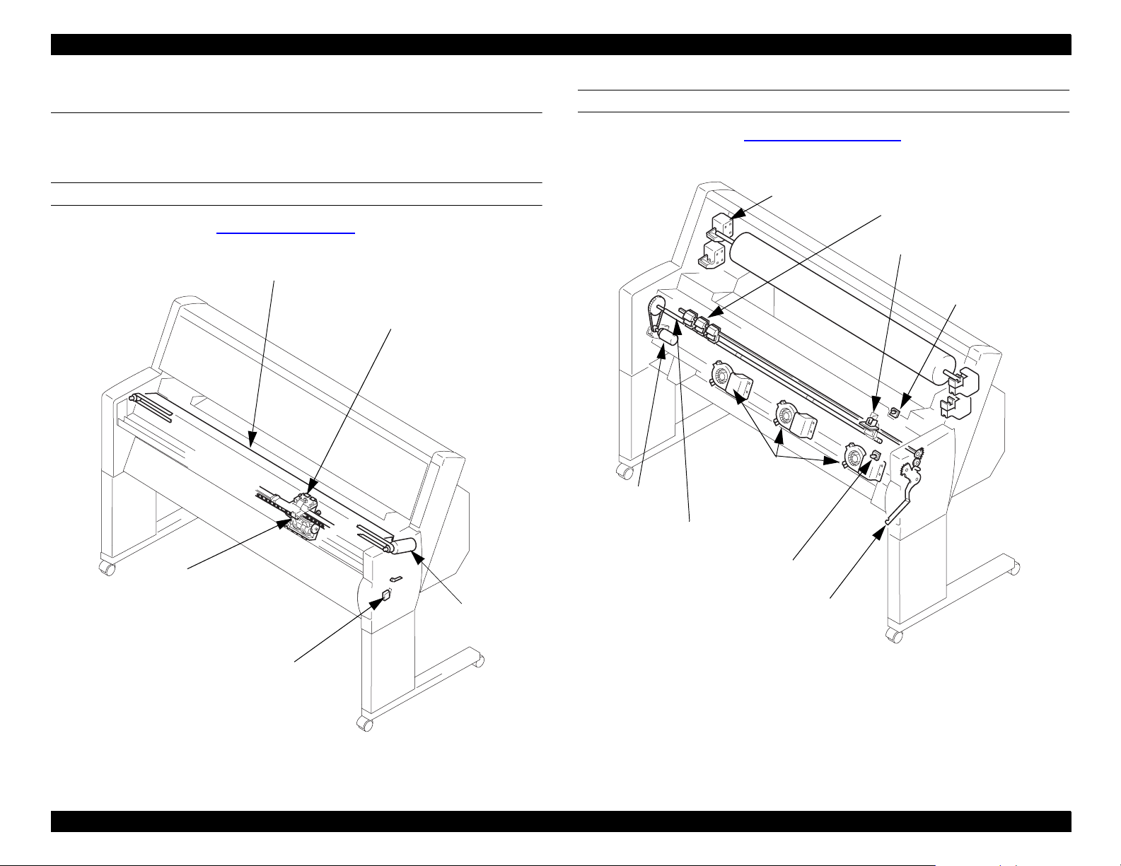
2.1 Location of Components
The following figures show the main components of the EPSON Stylus Pro
9000.
CARRIAGE MECHANISM
For more information, see
Car ria ge Mechanism
Guide Rail
on page 24.
HP Sensor/
Encoder
PAPER FEED MECHANISM
For more information, see
PF Motor
Paper Feed Mechanism
Roll Paper
Holders
Paper
Suction
Fans
on page 28.
Paper Pressure Rollers
Paper
ThicknessSensor
Rear Paper
Sensor
Paper Feed
Roller
Carriage
CR Motor
Cover Open Sensor
(interlock switch)
Front P a per Sens or
Paper Release Lever
Figure 2-2. Paper Feed Mechanism
Figure 2-1. Carriage Mechanism
Technical Overview 22
Page 23
EPSON Stylus Pro 9000
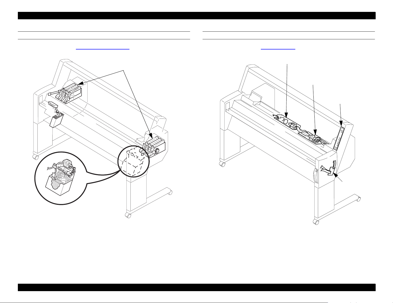
INK SYST EM
For more information, see
Flushing Box (L)
Waste Ink Pads
Ink Supply Mechanism
I/H Assembly
Pump Assembly
Wiper/Clea ner B l ade
Cap Assembly
CR Lock
Flush i ng Box (R)
Waste Ink Pads (R)
on page 34.
CIRCUIT BOARDS
For more information, see
Control Circuit
Power Supply Board
on page 37.
Main Board
(C277MAIN)
Control Panel
Relay
Board
Figure 2-3. Ink System
Figure 2-4. Circuit Boards
Technical Overview 23
Page 24
EPSON Stylus Pro 9000
2.2 Operation
The following sections describe how the printer’s main components operate .
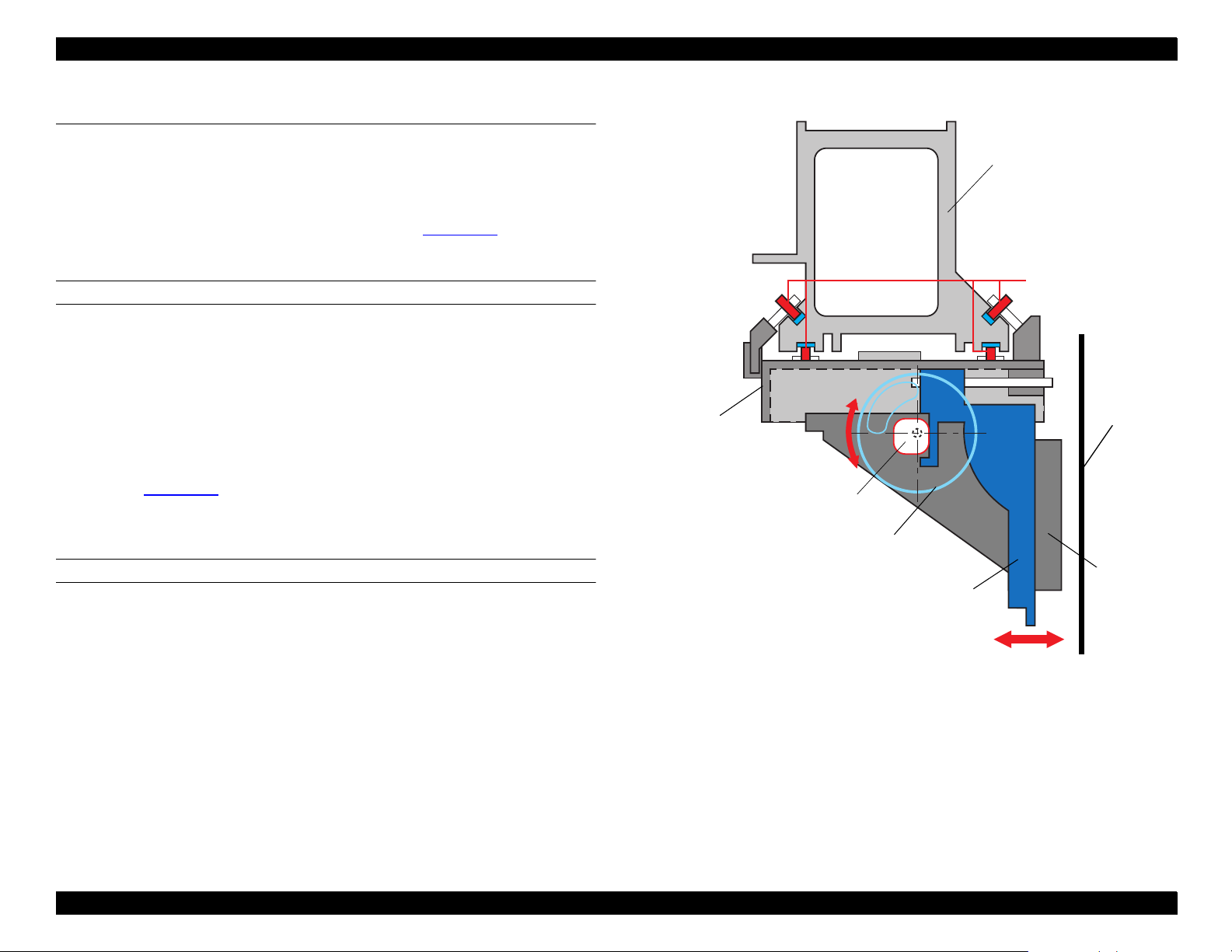
2.2.1 Carriage Mechanism
The carriage mechanism includes the parts shown in
operation is described below.
Figure 2-5
CARRIAGE (CR) GUIDE RAIL
To print on paper as wide as B0, the printhead carriage must be more stable
and must travel further than the usual carriage. To make the printheads more
stable, EPSON added the CR Guide Rail to the Stylus Pro 9000.
Every EPSON ink jet printer until now has used a carriage guide shaft to
stabilize the carriage during printing and horizontal movement. The
Stylus Pro 9000 does away with the carriage guide shaft and relies on the
printer frame for its stability.
As shown in
bearings, and the carriage in turn holds the subcarriage. The subcarriage holds
the printheads.
Figure 2-5
, the Carriage attaches to the CR Guide Rail with eight
. Their
Carriage
CR Guide Rail
Bearings
Platen
PG Cam
PG Gear
PLATEN GAP (PG) MECHANISM
Unlike previous models, the Stylus Pro 9000 uses a special system to ensure
that the distance between the printhead nozzles and paper remains the same
for all supported paper thicknesses. The subcarriage can be moved using the
PG Cam which is driven by the PG Gear; this causes the subcarriage and all its
components to move slightly nearer to or farther from the platen. The
subcarriage moves because the PG Cam is mounted off-center, so one side of
the cam pushes the subcarriage closer to the platen than the other side.
Subcarriage
Figure 2-5. CR Guide Rail and PG Mechanism (side view)
Printhead
Technical Overview 24
Page 25
EPSON Stylus Pro 9000
To maintain a constant distance between the printhead nozzles and the paper,
the printer measures the thickness of the paper and adjusts the height of the
carriage accordingly. The printhead has three platen gap (height) settings, as
described in the table below.
Table 2-1. Platen Gap Settings
Platen Gap Setting Gap Distance
PG “Small” 1.3mm
PG “Medium” 2.2mm
PG “Large” 2.7mm
The actual platen gap position used during printing depends on both the
detected paper thickness and the user’s paper thickness setting on the control
panel.
Table 2-2. Platen Gap Setting Determination
Control Panel Setting Paper Thickness Sensor Platen Gap Position
Wide Wide PG “Large”
Standard PG “Medium”
Auto Wide PG “Large”
Standard PG “Small”
PG Sensor
This light-reflecting sensor detects whether the subcarriage is in the thick
paper position or normal paper position. The PG Gear rotates with the PG
Cam, and the PG Sensor determines the subcarriage’s position from the
position of the PG Gear, using the hole in the gear’s side as a reference.
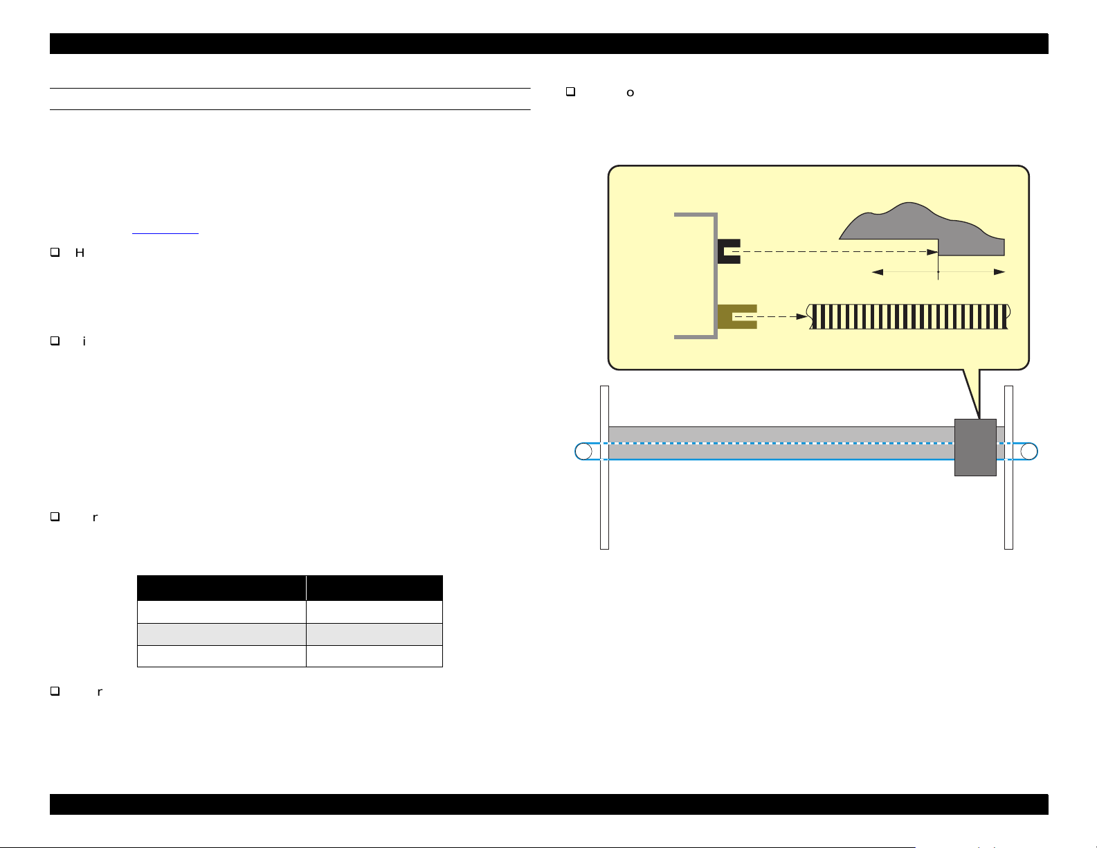
PAPER WIDTH SENSOR
This sensor locates the right and left edges of the paper. The light emitted from
the sensor is reflected back to the sensor where paper exists. In this way the
sensor determines where the paper’s edge is and how wide the paper is.
Carriage
Left
edge
Right
edge
Paper Width
sensor
HP side
The printer uses two sensors in setting the platen gap:
Paper Thickness Sensor
This sensor physically gauges whether the paper falls into the normal/thin
Paper
Figure 2-6. Paper Width Sensor
category or the thick category. The Pressure Roller unit closest to home
position has a thin metal flag on top. When the Paper Release Lever is in
the Lock position and thin paper is loaded, this flag pivots into the space
between the sensor’s light emitter and receiver. However, when thick
paper is loaded, the flag is forced forward out of the sensor area.
Sensor signal = ON at 0.7 V or less: Normal or thin paper
Sensor signal = OFF at 2.4 V or more:Thick paper
Technical Overview 25
Page 26
EPSON Stylus Pro 9000
CARRIAGE MOTOR AND POSITION CONTROL
For the greatest possible print accuracy and to minimize vibration, the printer
uses a DC motor to move the carriage. Because a rubber timing belt would
stretch over the long distance the carriage must travel during printing, the
Stylus Pro 9000’s timing belt is made from steel.
The following sensors are located on the carriage and control the carriage’s
position (see
HP Sensor
Figure 2-7
This optical sensor activates when the CR Guide Rail flag enters the space
between the sensor’s light emitter and the light receiver. The flag is located
just above home position, and the HP sensor sends an ON signal when the
carriage is in home position.
Linear Encoder Sensor
This sensor determines the position of the carriage by counting bands on
the timing fence (timing strip) while the carriage is in motion. The bands
have a distance equal to 180 dpi. For every band the Linear Encoder
passes over, it sends a print timing pulse to the software servo system.
The software servo forms a closed-loop with the CR motor and Encoder
Sensor. It receives feedback from the Encoder Sensor and adjusts the
current to the CR motor to maintain constant carriage speed.
):
CR Motor Motion Failure
During operation, the encoder measures the distance the carriage travels. If
the CR speed as determined by the encoder varies too much from the speed
set by the Software Servo, a fatal error occurs (Service Call 00010005).
CR Guide Rail flag (projected
Carriage
area)
HP Sensor
No HP signal
HP signa l
Linear
Encoder
Timing Strip
Carriage Speed and Acceleration
Carriage Speed
Carriage
The carriage speed during printing is described below.
Table 2-3. Carriage Speed
Figure 2-7. Carriage Mechanism Sensors
Print Mode Carriage Speed
720 dpi & Normal M/W 200 cps
4 Pass FOL printing 300 cps
Unidirectional 400 cps
Carriage Acceleration
Due to the carriage’s quick acceleration, even after the heads reach and
maintain normal speed, they are not stable enough to print for the next 10 mm.
Technical Overview 26
Page 27
EPSON Stylus Pro 9000
CUTTER MECHANISM
To make a paper cut, the cutter solenoid plunges the cutter blade into the
paper. To cut the paper evenly, the following method is used:
1)The cutter cuts from the left of center (when facing the printer) to the left
edge.
2)The cutter cuts from several centimeters inside the right edge to the right
edge.
3)The cutter cuts the remaining center portion, from right to left.
Cutter
Carriage
solenoid
PRINTHEADS
The printheads are the same type used in the EPSON Stylus Pro 5000, and
are installed in the same way. Three levers are provided to make sure the
heads are lined up vertically and that neither head leans one way or the other.
Cutter
Blade
Paper
Figure 2-8. Cutter Mechanism
Technical Overview 27
Page 28
EPSON Stylus Pro 9000
2.2.2 Paper Feed Mechanism
The main components of the paper feed mechanism are described below.
PAPER FEED MOTOR AND ROLLERS
When paper is loaded, it’s held against the Paper Feed Roller by the Paper
Pressure Rollers. Raising the Paper Release Lever (see
the Paper Pressure Rollers away from the Paper Feed Roller, and releases
any loaded paper. The Paper Feed Roller Assembly is made up of three equal
lengths of rollers and their coupling.
Figure 2-10
) moves
CR Guide
Rail
Speed-
Reduction
Gear
Paper Pressu r e
Roller
Paper Fe ed
Roller
The PF Motor uses a DC motor, which has a built-in optical rotary encoder. The
encoder sends signals to the software servo system, which regulates the
speed of the motor. Motion is transferred through a timing belt to the SpeedReduction Gear, which improves the accuracy of paper feeding.
Platen
Subplaten
Paper
PF Motor
Figure 2-9. Paper Feed Mechanism
Technical Overview 28
Page 29
EPSON Stylus Pro 9000
PAPER FEED SENSORS
The printer relies on the following sensors for paper feeding:
Front Paper Sensor
This optical sensor is attached to the back side of the Lower Paper Guide,
and detects the front edge (top or leading edge) of the paper.
Rear Paper Sensor
This optical sensor is attached to the back side of the Lower Paper Guide,
and detects the rear edge (bottom or trailing edge) of the paper.
Paper Release Lever Position Sensor
The Paper Release Lever is located on the right side of the pri nter, and the
sensor attaches to the bottom of the lever, inside the right-side frame. This
sensor’s signal is ON when the lever is in down, which allows the printer to
print.
Rear Paper
Sensor
Paper Thickness
Sensor
Paper Release
Lever
Front Paper
Sensor
Paper Release Lever
Position Sensor
Figure 2-10. Paper Feed Sensors
Technical Overview 29
Page 30
EPSON Stylus Pro 9000
PAPER SUCTION FAN
The Paper Suction Fans are located behind the lower paper guide and suck air
through the holes in the guide. This keeps the paper from bulging as it feeds
through the printer and prevents ink smears. The table below relates fan speed
to various printer states and user actions.
Table 2-4. Fan Speeds
Fan speed User action Printer action Sensor state LCD message
Level 1 (low) User begins to load paper —
Level 2 (medium) User continues loading paper —
Rear Paper Sensor ON
Front Paper Sensor OFF
Rear Paper Sensor ON
Front Paper Sensor ON
“Load Paper” if Paper
Release Lever UP
“Paper Out” if Paper Release
Lever DOWN
“Load Paper” if Paper
Release Lever UP
“Press Pause Button” if Paper
Release Lever DOWN
Fan goes from
Level 3 (high) to
Off, and then
back to Level 3
(high) during
paper setting
sequence
Off —
Level 3 (high) User sends print data Printing
User lowers Paper Release
Lever and presses Pause, or
user allows several seconds
to pass after lowering Paper
Release Lever and prin ter
automatically ends “Pause”
state
Printer sets paper
Paper loaded and
printer waiting for
print data
Depends on paper’s location
while being set
Rear Paper Sensor ON
Front Paper Sensor ON
Depends on paper’s location
while printing
“Wait”
“Ready”
“Printing”
Technical Overview 30
Page 31

EPSON Stylus Pro 9000
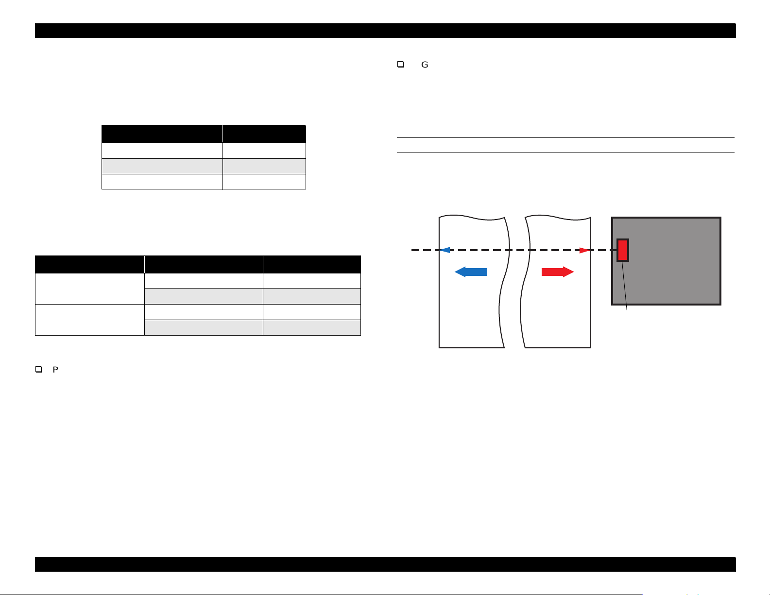
PAPER WIDTH DETERMINATION (LEFT AND RIGHT EDGE DETECTION)
Before printing, the printer sets the platen gap and then flushes the printheads
to make sure no ink smears the paper. The printer then detects the left and
right edges of the paper. Note how “left” and “right” are defined below:
Right Paper Edge
Left Paper Edge
Printable Area
To detect the left and right edges, the printer performs the following steps:
Table 2-5. Left and Right Edge Detection
Purpose Step Action
To make sure
paper is
loaded
correctly
The carriage moves just to t he inside of where the left edge
1
should be, if the paper is loaded correctly.
The Paper Width Sensor checks for paper. If paper is
2
detected, go to step 3; otherwise report “Reload Paper” error.
Table 2-5. Left and Right Edge Detection (continued)
Purpose Step Action
To determine
position of lef t
edge
To determine
position of
right edge
To verify left
edge position
and determine
paper width
The carriage move s to the left paper edge and regi sters its
7
position.
8 The carriage moves to the right edge of the paper.
The Paper Width Sensor checks for paper. If paper is not
9
detected, go to step10; otherwise, report “Reload Paper”
error.
The printer registers the position of the right edge of the
10
paper.
11 The carriage returns to th e lef t paper edge.
The Paper Width Sensor checks for paper. If paper is not
12
detected, go to step13; otherwise, report “Reload Paper”
error.
The printer verifies the edge position and registers the
13
distance from one edge of the paper to the other.
To establish
sensor signal
level
To make sure
paper is
loaded
correctly
To establish
sensor signal
level
The printer registers the sensor’s “paper present” (ON) signal
3
level.
The carriage moves just to t he outside of where the left edge
4
should be, if the paper is loaded correctly.
The Paper Width Sensor checks for paper. If paper is not
5
detected, go to step 6; otherwise report “Reload Paper” error.
The printer registers the sensor’s “no paper” (OFF) signal
6
level.
Technical Overview 31
Page 32

EPSON Stylus Pro 9000
PAPER SIZE DETERMINATION (DETECTION OF TOP EDGE)
If the printer is in Roll Auto Cut or (Cut) Sheet mode, it determines the location
of the top (leading) edge of the paper before printing. Note that the printer skips
this procedure if Roll Cutter Off is selected.
The “top-left” and “top-right” edges are as shown below. Note that the top edge
may not be straight across.
Printable Area
Top-R i ght Pape r Edge
After determining the position of the left and right edges of the paper (see
Paper Width Determination (Left and Right edge Detection)
the printer performs the following steps to locate the top edge and correctly
position the paper for printing:
Top-Left Paper Edge
on page 31),
Table 2-6. Top Edge Detection and Positioning
Purpose Step Action
Printer reverse feeds (pulls paper back up) a maximum
To make sure
paper is
loaded
correctly
To determine
top-left edge
position
To determine
top-right edge
position
To ready
carriage for
printing
1
distance of 200mm.
The Front Paper Sensor checks for paper. If, during rever se
2
feeding, it detects the top edge of the paper, go to step 3;
otherwise, report “Reload Paper” error.
Carriage moves from home posit ion to 30 mm inside lef t edge
3
of paper.
4 Printer reverse feeds 200 mm max.
The Paper Width Sensor checks for paper. If, duri ng reverse
5
feeding, it detects the top edge of the paper, go to step 6;
otherwise, report “Reload Paper” error.
6 Printer registers top-left edge position.
7 Carriage moves to 30 mm inside right edge.
The Paper Width Sensor checks for paper. If it det ects paper,
the printer reverse feeds paper until Paper Width Sensor
8
detects top-right edge. If paper n ot detected, printer advances
paper until Paper Width Sensor detects top-right edge.
9 Carriage returns to home position.
To set paper
for printing
Printer advanc es paper so that the shorter of the two edges
10
(top-left or top-right ) aligns with a position approx imately 1 cm
below the level of the Fr ont Paper Sensor.
Technical Overview 32
Page 33

EPSON Stylus Pro 9000
PAPER LOADING ERRORS
“Reload Paper” Error
After paper is loaded in the printer, the printer performs the left, right, and
leading edge detection operations described above. If the operations fail at
any point, a “Reload Paper” error occurs.
“Paper Not Straight” Error
To avoid printing on paper that is skewed or fed at a slant too far to the
right or left, the printer detects the right and left edges at the leading edge
of each page. If the printer determines that the paper is skewed 3 mm or
more from the position previously detected, a “Paper Not Straight” error
occurs.
To avoid paper loading errors, make sure the paper’s left edge (near HP) is
lined up with the vertical line of holes in the Lower Paper Guide. Paper loaded
within 10 mm of the center of the vertical line of holes in the Lower Paper Guide
is considered in the printable zone; however, paper loaded outside that 10 mm
zone causes an error.
2.2.3 C arriage Lock Mechanism
The printer uses an electromagnetic solenoid to release the carriage lock.
When the carriage lock does not receive any signal, the actuator rises into the
opening at the bottom of the subcarriage, restricting carriage movement. To
release the carriage for printing, the printer signals the actuator which then
moves down, releasing the carriage.
Carriage Cover
Locking Actuator
CR Lock
Release
Lever
Figure 2-11. Carriage Lock Mechanism
Technical Overview 33
Page 34

EPSON Stylus Pro 9000
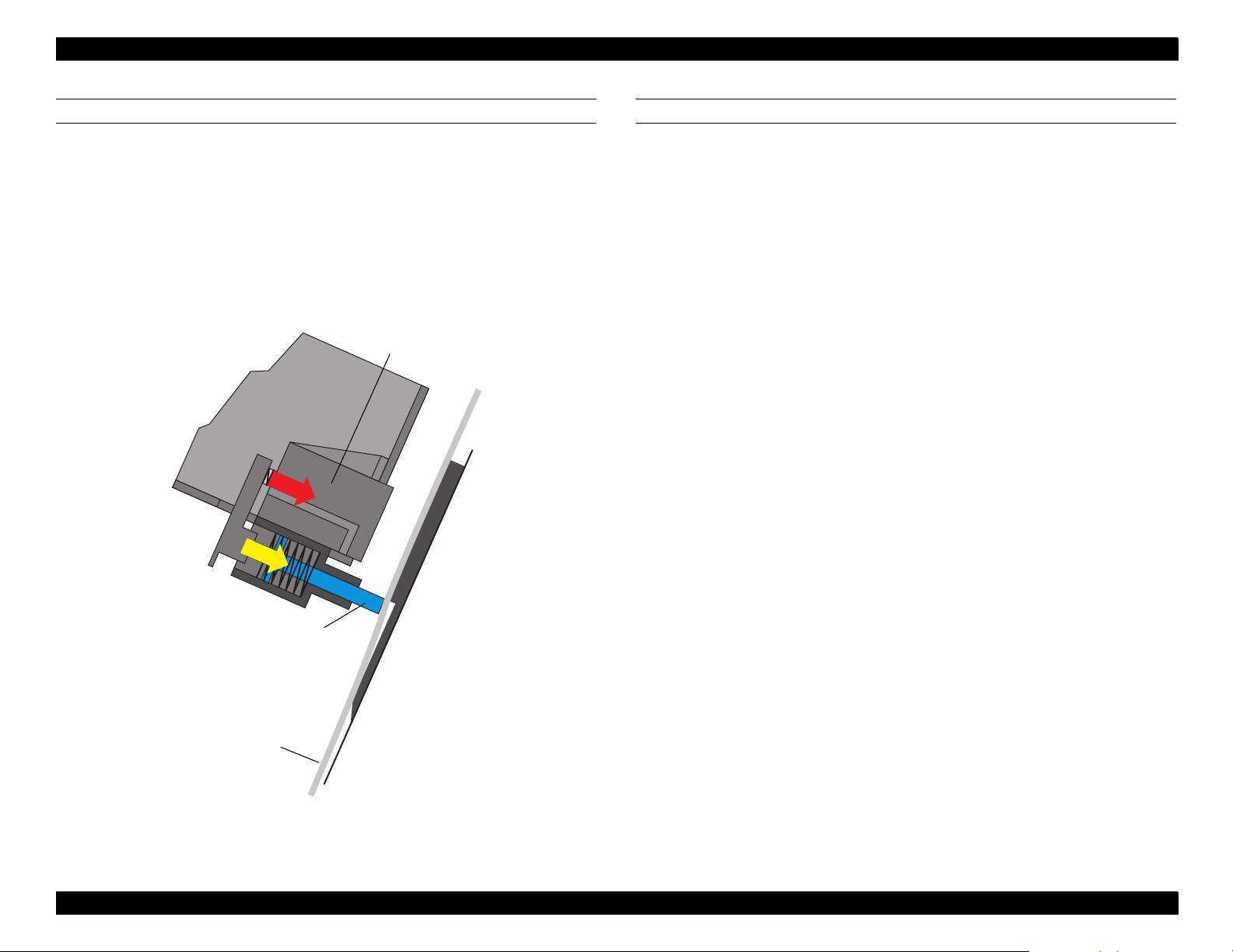
2.2.4 Ink Supply Mechanism
The two ink cartridge holders each hold three cartridges, K, C, and M on one
side and Lc, Lm, and Y on the other side. The design of the holders makes it
quite easy to install and replace ink cartridges from the front of the printer. The
I/H Lever opens and closes the I/H door, and at the same time it changes the
angle of the Ink Cartridge Holder Assembly as shown in
page 34. To prevent users from accidently installing a color ink cartridge in the
wrong slot, the cartridges have slightly different designs.
Another important feature of the ink cartridge holders is the ink valve, which is
located on the outer sides of the ink cartridge holders. It can be used to shut off
the flow of ink during printer transportation. The valve is closed when:
the user turns the valve to the “CLOSE” position
the I/H lever is lifted to install cartridges
When the valves are open, the ink flows out of the ink cartridges, through the
stainless steel pipes, through the ink tubes, and finally into the printheads.
Figure 2-12
on
I/H Lever
Ink Cartridge
Holder Assembly
Figure 2-12. Ink Supply Mechanism
Technical Overview 34
Page 35

EPSON Stylus Pro 9000
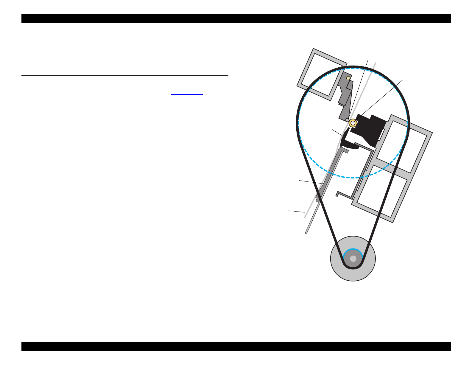
INK-RELATED SENSORS
The following sensors are located in the I/H compartment:
I/H Assembly sensor
This optical sensor detects the whether the door is open and the I/H
Assembly is in the install position or the door is closed and the I/H
Assembly is in the print position.
When the I/H door is open, the signal = ON
When the I/H door is closed, the signal = OFF
Ink Cartridge sensor
This mechanical sensor (microswitch) is built in all six ink cartridge slots.
When the I/C is installed, switch = closed
When the I/C is not installed, switch = open
Ink Low sensor
This mechanical sensor (microswitch) is at the bottom of all six ink
cartridge slots and detects when ink is running out.
When the I/C is nearly empty, the switch = open
When the I/C is not low (normal), the switch = closed
Ink ID sensor
This optical sensor is located on the side of all six ink cartridge slots and
detects which market the cartridge is for. Although not currently
implemented, the sensor can also detect the type of ink (presently dye
only) and any special color (if new colors are introduced in the future).
The Ink ID sensor looks for the following marks on the ink cartridge.
Ink Cartridge
Figure 2-13. Ink Cartridge Holder Sensors
Ink ID Sensor
Ink Low Sensor
Ink Cartridge Sensor
Market: No mark, white = Overseas/Global
Ink type: No mark, white = dye-based ink
Special color: No mark, white = N/A (may be available in future)
Technical Overview 35
Page 36

EPSON Stylus Pro 9000
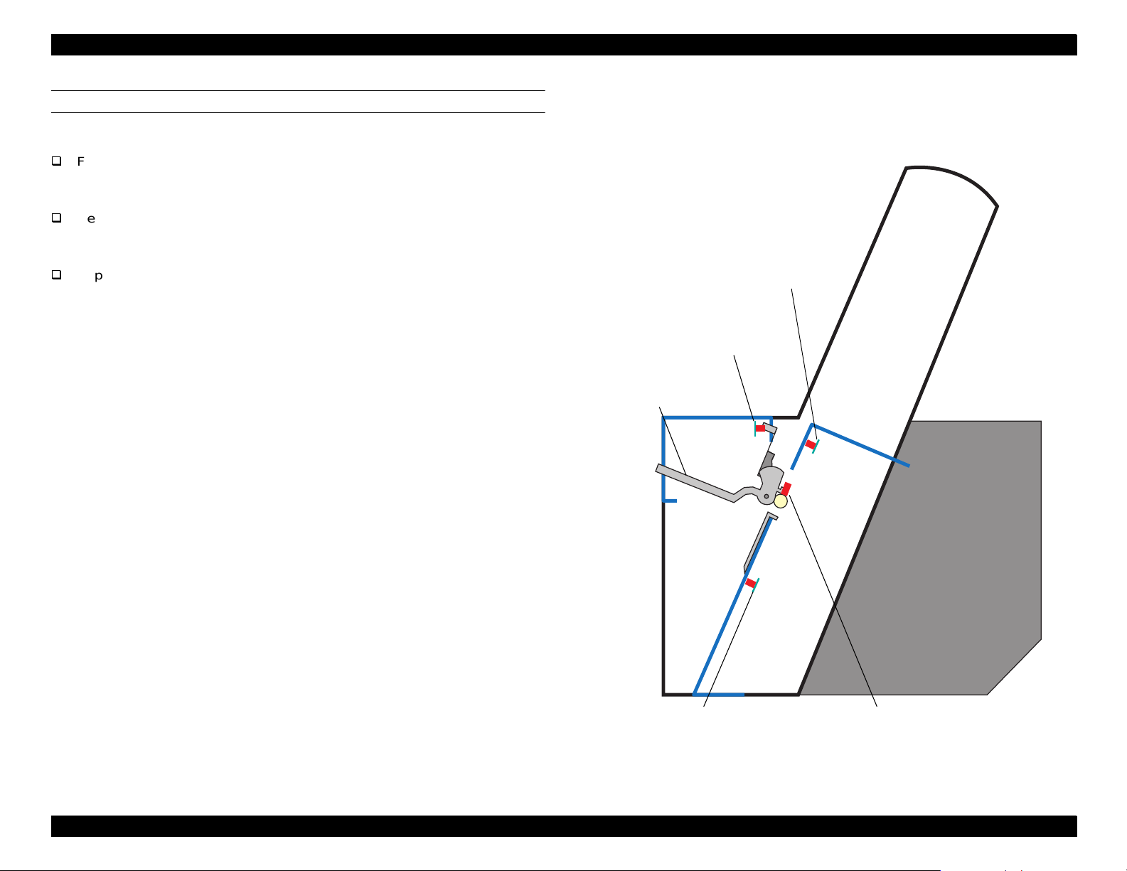
2.2.5 Cover Ope n Se ns or
There are two cover open sensors, or safety interlock switches, one on each
side of the printer, that detect when the cover is open. When the cover is open,
relays that control current to the CR motor and PF motor cut off the flow of
current. As shown in
from damaging drivers and other circuitry when the relays shut off.
Figure 2-15
Front
Cover
, a bypass capacitor prevents current spikes
CR
Motor
PF
Motor
Driver
Front Co v er
open
Cover Open
Sensor
Figure 2-14. Cover Open Sensor
Driver
C126/127
Figure 2-15. Relay Circuit Between Cover Open Sensors and
Printer Motors
Technical Overview 36
Page 37

EPSON Stylus Pro 9000
2.2.6 Control Circuit
This section summarizes the functions of the (C277MAIN) Main Board.
Motor
drivers
Printer
mechanism
IC8
CPU/C90A08CA
(SH7043)
IC13
ASIC/E05B61AA
IC32
ASIC/uPD65802
IC33
Motor
CR
IC35
PF
Motor
IC20
ASIC/TE7751
IC30
PG
Motor
CN7
Control Panel
IC31
Pump
Motor
IC39
SRAM/8KB
IC18/19
DRAM/2MB
CN19
RAM-SIMM/16MB
IC1/2
Flash mem./1MB
CN20
PC Card connector
Head data & control signals
IC37
DAC/M65530FP
B head C head
Head-drive voltage
common driver
Printheads (B/C)
CN2
Type-B Slot
CN3
Mac Serial I/F
CN1
Parallel I/F
Fixed
-Firmware
-Setting parameters
Head-drive wave
generation
Table 2-7. C277MAIN Board Main Components
Name/Code Location Function
CPU (C90A08CA)
SH7043
IC8
ASIC (E05B61AA) IC13
ASIC (TE7751) IC20
ASIC (uP D65802) IC32
DAC (M65530FP) IC37
Flash Memory
(MBM29F400TC)
IC1/2
DRAM (EDO) IC18/19
SRAM (LC3564SM-
10)
IC39
Driver IC (L6203) IC33/35 CR/PF Motor Driver
Driver IC (LB1845) IC30/31 PG/Pump Motor Driver
32 bit RISC-CPU
Clock speed = 33M H z
128KB PROM internal
Regulates print data
Command handling
Rasterizer (image da ta handling)
Head drive regulation (DAC)
Print timing regulation
Memory (DRAM /SR AM)
I/F Circuit Control
Parallel interface (IEEE1284)
Macint osh Serial interface
Type-B
Regulates Motor
Pump Motor
PG Motor (PG setting)
Fan (PS, Paper Suction)
Regulates motor (PWM regul ation)
CR Motor
PF Motor
3 channel 10 bit DA converter
head-drive voltage control
Fla sh Me mory (1Mbyte)
Save firmware
Register setting parameters
EDO RAM
2Mbyte
16Mbtye (CN19 mounted SIMM)
64Kbit SRAM
External da ta ring buffer type
Figure 2-16. C277MAIN Board-Circuit Block Diagram
Technical Overview 37
Page 38

TROUBLESHOOTING
Page 39

EPSON Stylus Pro 9000
3.1 Overview
To troubleshoot printer problems, turn to one of these sections:
If the LCD display shows an error message, see
LCD Error Messages
Since an LED or LCD error message may indicate a loose cable connector,
see also
If you notice problems with print quality such as missing dots or lines,
misaligned vertical lines, or banding (faint white lines), see
Troubleshooting
Connector-Related Errors
on page 39.
on page 52.
on page 49.
Trouble shooting Usi ng
Print Quality
3.2 Troubleshooting Using LCD Error Messages
The EPSON Stylus Pro 9000 performs self-diagnostic tests using the data
supplied by its sensors, and if an error is detected by one or more sensors, an
error message appears on the control panel display.
When the printer displays an error, look it up in
follow the link in the table to the appropriate troubleshooting section of this
chapter.
Table 3-1
or
Table 3-2
and
Troubleshooting 39
Page 40

EPSON Stylus Pro 9000
3.2.1 LCD Error Messages
When a part reaches the end of its useful life, an error code appears on the
printer’s LCD display. For example, MAINTENANCE REQ. 0100 appears on
the display to warn that the Waste Ink Pads are about 99% full. The printer
continues to print while this message appears. When the Waste Ink counter
determines that the Waste Ink Pads are completely full, the printer displays
SERVICE REQ. 00000100 and stops printing.
Error codes also alert the user to fatal errors and other printer problems. Refer
to the tables below to determine the meaning of each code.
Table 3-1. Error Message List for Service Technicians
Error Code Description Refer to
Maintenance
Req. nn
Service Req.
nnnnnnnn
Service Req.
nnnnnnnn
0100
0000010 0 Waste Ink pads must be replaced
00000101 Ink Tube wor n out
00010000 PF motor encoder check error
0001000 1 PF motor out of step
00010002 PF motor overcurrent
00010003 PF in-position time-out
00010004 CR motor enco der check error
0001000 5 CR motor out of ste p
00010006 CR motor overcurrent
00010007 CR in-position time-out
00010008 Servo interrupt watchdog time-out error
00010009 System interrupt watchdog time-out error
0001000A CR origin sensor malfunction
0001000C PG origin sensor malfunction
0001000D Cov er sensor m alf un ction (00 )
000100 0E Cover sens or m alfunct io n (0 1 )
0001000F CR motor PWM output error
00010010 PF motor PWM output er ror
0002000 0 NVRAM error
Waste Ink pads is almost full (les s than 1%
remaining)
page 41
page 41
page 41
page 41
page 41
page 42
page 42
page 42
page 42
page 43
page 43
page 43
page 43
page 43
page 43
page 44
page 44
page 44
page 44
page 44
Table 3-1. Error Message List for Service Technicians (continued)
Error Code Description Refer to
000200 01 Internal RAM check erro r
00020002 SRAM check error
00020003 DRAM check error
0002000B Mail Box receiving error
10000004 CPU vector 4 - General illegal instruction
10000006 CPU ve ctor 6 - Slot illegal in st r uc tion
10000009 CPU vector 9 - CPU address error
1000000A CPU vector 10 - DMAC/DTC address error
1000000B CPU vector 11 - Watchdog time-out error
100000”” CPU vector 32 to 63 - Wrong trap
page 44
page 44
page 44
page 44
page 44
page 44
page 44
page 44
page 44
page 44
Table 3-2. General Error Message List
Error Type Message Refer to
Warning Ink Low
Paper Out
Load xxx Paper
Load Paper
Paper Jam
Cover Open
Paper Not Cut
Paper Not Straight
Error
Reload Paper
Push Lever Down
Compartment Open
Ink Out
No Ink Cartridge
Remove Paper
Option I/F Error
page 45
page 45
page 45
page 45
page 46
page 46
page 46
page 46
page 47
page 47
page 47
page 48
page 48
page 48
page 48
Troubleshooting 40
Page 41

EPSON Stylus Pro 9000
3.2.2 Errors that require a service technician
This section describes the errors listed in
MAINTENANCE REQ. 0100
Problem
The Waste Ink Pads have absorbed 99% of their ink capacity. The printer
can continue printing, but the “Maintenance Req. 0100” message appears
instead of the “Ready” or “Printing” messages.
Solution
Replace the Waste Ink Pads along with the replaceable parts of the
Mainenance Assembly as described in
page 67.
SERVICE REQ. 00000100
Problem
The waste ink pads are completely full, causing a fatal error. The printer
stops printing.
Solution
See the solution for Maintenance Req. 0100, above.
SERVICE REQ. 00000101
Problem
This error occurs when the CR Motor has reached 2.5 million passes,
which indicates that the Ink Tubes should be replaced due to excessive
wear and tear.
Solution
Replace the Ink Tubes as explained in
page 92.
Table 3 - 1
Maintenance Procedures
Removing the Ink Tubes
on page 40 in detail.
on
on
SERVI C E R EQ. 00010 000
Problem
PF motor encoder check error
When the PF motor turns, the printer checks the rotary encoder output
signals to make sure the motor is turning at the correct speed and
distance. If the encoder doesn’t send the expected output data, an error
occurs.
Solution
Make sure there is nothing blocking the PF Roller. If that does not solve the
problem, check the PF motor encoder connection. If there still is a problem,
try the following:
Check and adjust the PF Belt tension
Replace the PF motor
Replace the Main Board
SERVI C E R EQ. 00010 001
Problem
PF motor out of step
The length of the pulse generated by the PF motor’s internal encoder is too
long or too short compared to the normal pulse.
Solution
See the solution for Service Request 00010000, above.
Troubleshooting 41
Page 42

EPSON Stylus Pro 9000
SERVICE REQ. 00010002
Problem
PF motor overcurrent
Feedback from the PF motor driver (IC35) indicates that the PF motor’s
current is irregular.
Solution
Replace the PF motor
Replace the Main Board
SERVICE REQ. 00010003
Problem
PFin-position time-out
The in-position time is the amount of time the printer waits to make sure the
PF Roller is not moving when the motor comes to a stop. If the rotary
encoder sends a pulse during the in-position time, then the PF Roller is
moving even though it’s supposed to be at a full stop, and this generates
an error.
Solution
Replace the PF motor
Replace the Main Board
SERVI C E R EQ. 00010 004
Problem
CR motor (linear) encoder check error
When the CR motor turns, the printer checks the linear encoder output
signals to make sure the motor is turning at the correct speed and
distance. If the encoder doesn’t send the correct output data, an error
occurs.
Solution
Make sure there is nothing blocking the carriage. If that does not solve the
problem, check the linear encoder’s connections. If there still is a problem,
try the following.
Check the plastic encoder strip (timing fence) for soiled areas,
obstructions, and damage
Replace the linear encoder sensor
Replace the CR motor
Replace the Main Board
SERVI C E R EQ. 00010 005
Problem
CR motor out of step
The length of the CR motor’s pulse is too long or too short compared to the
normal pulse.
Solution
See the solution for Service Request 0010004, above.
Troubleshooting 42
Page 43

EPSON Stylus Pro 9000
SERVICE REQ. 00010006
Problem
CR mo t or overc urre nt
Feedback from the CR motor driver (IC33) indicates that the CR motor’s
current is irregular.
Solution
Replace the CR motor
Replace the Main Board
SERVICE REQ. 00010007
Problem
CR in-position time-out
The in-position time is the amount of time the printer waits to make sure the
carriage is not moving when the carriage comes to a stop. If the linear
encoder sends a pulse during the in-position time, then the carriage is
moving even though it’s supposed to be at a full stop, and this generates
an error.
Solution
Replace the linear encoder sensor
Replace the CR motor
Replace the Main Board
SERVICE REQ. 00010008
Problem
Servo interrupt watchdog time-out error due to motor-drive control related
error
Solution
Replace the Main Board
SERVI C E R EQ. 00010 009
Problem
System interrupt watchdog time-out error due to sensor-related error
Solution
Replace the Main Board
SERVI C E R EQ. 00010 00A
Problem
CR origin (home position) sensor malfunction
Solution
Check the HP sensor for obstructions, and clean using compressed air
Replace the HP sensor
Replace the Main Board
SERVI C E R EQ. 00010 00C
Problem
PG origin sensor malfunction (may indicate PG motor malfun ction)
Solution
Make sure there is no ink or dust on the surface of the sensor. If this does
not solve the problem, check the PG sensor’s connections. If there still is a
problem, try the follo w in g:
Replace the PG sensor
Replace the PG motor
Replace the Main Board
Troubleshooting 43
Page 44

EPSON Stylus Pro 9000
SERVICE REQ. 0001000D SERVICE REQ. 0001000E
Problem
Cover sensor malfunction
One or both Cover Open sensors (interlock switches) located at either end
of the cover shaft is malfunctioning.
D: right sensor (HP side)
E: left sensor
Solution
Make sure each sensor is properly installed. If that does not solve the
problem, check the Cover Open sensor’s connections. If there still is a
problem, try the following:
Replace the malfunctioning sensor or sensors
Replace the Main Board
SERVICE REQ. 0001000F
Problem
CR motor PWM output error
Solution
Replace the Main Board
SERVICE REQ. 00010010
Problem
PF motor PWM output error
Solution
Replace the Main Board
SERVICE REQ. 00020000 (NVRAM ERROR)
SERVICE REQ. 00020001 (INTERNAL RAM ERROR)
SERVICE REQ. 00020002 (SRAM ERROR)
SERVICE REQ. 00020003 (DRAM ERROR)
SERVICE REQ. 0002000B (MAIL BOX RECEIVING ERROR)
Problem
Unusual condition detected.
Solution
Write down the error code, and then turn the printer off and back on to
confirm that the error recurs. If the error recurs, replace the Main
Board.
For “Service Req. 00020003” (DRAM error), replace the SIMM
installed in CN19 and then check whether the error recurs.
SERVI C E R EQ. 10000 004
SERVI C E R EQ. 10000 006
SERVI C E R EQ. 10000 009
SERVICE REQ. 1000000A
SERVICE REQ. 1000000B
SERVI C E R EQ. 10000 0##
Problem
Unusual condition detected.
Solution
Write down the error code, and then turn the printer off and back on to
confirm that the error recurs. If the error recurs, replace the Main
Board.
Send a different print job to make sure the error wasn’t due to electrical
noise or bad print data.
(CPU GNRL ILLEGAL INSTRCTNS)
(CPU SLOT ILLEGAL INSTRCTNS)
(CPU CPU ADDRESS ERROR)
(CPU DMAC/DTC ADDRESS ERROR)
(CPU WATCHDOG TIME-OUT ERROR)
(CPU VECTOR 32~63)
Troubleshooting 44
Page 45

EPSON Stylus Pro 9000
CAUTION
3.2.3 General Errors
This section describes the errors that can be solved by the user.
INK LOW
Problem
Each ink cartridge has a mechanical ink level gauge. One of them has
detected that the corresponding ink cartridge is almost empty. With the
remaining ink, the user can still print at about 100% duty on B1 size paper,
but the cartridge should be replaced as soon as possible.
Solution
Replace the ink cartridge with a new one. Do not try to reuse the old
cartridge; if you re-install an ink cartridge that was detected as being in a
“Near End ” sta te, the s tat us w ill im mediately g o to “Ink Ou t . ”
ADJUSTM ENT
REQUIRED
PAPER OUT
If for any reason you replace an ink cartridge before it
reaches the ink-low or ink-out state with a new ink
cartridge, you need to reset the ink counter from the
control panel. See Maintenance Mode 2
on page 17.
Solution
If paper has run out, remove the printer paper and load new paper. If
print data remains in the printer, the data will be printed.
If this error occurs even though paper is properly loaded, there may be
something on the Rear Paper Sensor’s surface. Clean the sensor’s
surface (hole in the Upper Paper Guide) with a clean, dry cloth or using
compressed air.
Never use a wet cl oth or soap to clean opti cal s en sors.
LOAD XXX PAPE R
Problem
The selected paper source (according to the remote PP command) and the
paper type selected on the control panel do not match.
Solution
Load the correct paper or change the panel setting to match the type of
paper loaded in the printer.
Problem
Paper is not loaded.
The rear edge of roll paper has been detected.
The print job using cut sheets is finished or the rear edge of cut-sheet
paper has been detected.
LOAD PAPER
Problem
While paper is loaded, the Paper Release lever was pushed up to the
Release position.
Solution
Make sure paper is loaded properly and push down the Release lever
to lock the paper in place.
If this error occurs even when the lever is down, in the Lock position,
there may be a problem with the Paper Release lever sensor. Check
the sensor’s operation and connectors. If that doesn’t work, replace the
Main Board.
Troubleshooting 45
Page 46

EPSON Stylus Pro 9000
PAPER JAM
Problem
A paper jam occurs when during printing, paper feeding, or paper cutting,
and the carriage is not able to move properly (due to paper catching on
some part). The printer determines a paper jam has occurred if the Front
and Rear Paper sensors are ON but the carriage motor is out of step or
drawing too much current.
Solution
After removing the jammed paper, turn the printer off and back on
again.
If a paper jams occurs again after removing the original paper jam,
check to make sure nothing is blocking the feed path or blocking the
carriage.
COVER OP EN
Problem
The front cover is open.
This error occurs when the cover is opened during carriage operation or a
cleaning operation, causing printer operation to stop. If the carriage is not
in home position and the cover is left open too long, the printheads may dry
out and become damaged. (To avoid this problem, press the Pause button
before opening the cover. Note that if you continue printing, a stripe or
band may appear where printing resumes; this is because the previously
printed section has had more time to dry than the freshly deposited ink.)
Solution
Close the cover as soon as possible.
If the cover is fully closed when this error occurs, make sure the left
and right cover-open sensors are correctly installed and are operating
properly.
PAPER NOT CUT
Problem
The paper that was supposed to be cut was not cut completely, or the
paper wa s c ut but is still in front of the Fr ont Paper Sen so r .
Solution
Remove the cut paper if it is on or near the Front Cover and Lower
Paper Guide.
Replace the cutter if it is worn out.
If the paper was cut, but not cut straight across, you may need to
adjust the cutter position. See
page 131 for details.
Cutter Position Adjustment
on
PAPER NOT STRAIGHT
Problem
This error occurs when the printer detects that the paper is skewed (loaded
at an angle) by more than 3 mm. If the printer prints on paper that is loaded
at a slant, the printer may print outside of the printable area and may fire
ink onto the platen. If this happens, the next sheets loaded in the printer
may be marred on the back.
Solution
Remove the paper loaded in the printer and properly reload it so that
it’s edge is aligned with the vertical line of holes in the Lower Paper
Guide.
If using roll paper, remove the roll and carefully squeeze the sides of
the roll to make sure they’re lined up and flat.
Troubleshooting 46
Page 47

EPSON Stylus Pro 9000
RELOAD PAPER
Problem
This error occurs when:
1) The user loads the paper too far down (more than 200 mm below the
Front Paper Sensor).
2) The paper was loaded in such a way that the left edge is not within
10 mm of the vertical line of holes in the Lower Paper Guide.
3) The right edge is outside the printable area (due to mis-loading or
because the paper is too wide).
4) After printing has finished, the right or left edge is outside the area
where the cutter can cut the paper.
5) The loaded paper was longer than the selected paper, and the paper
was not fully ejected. (For example, roll paper is loaded in the printer but
cut sheet is selected on the control panel.)
6) A cutter error occurred after the paper was ejected.
Solution
for 1 through 4, above
Reload paper properly. If the front edge of the paper is not straight and
clean, cut the paper.
for 5 and 6, above
Cut off the ejected portion of the paper and reload the rest of the
paper. For paper that is automatically cut, lift up the Release Lever (the
“Load Paper” message appears), fix the position of the paper, and
lower the Release Lever. If you select the “Roll Auto Cut” setting, you
can cut off the ejected portion of the paper using the Cut button.
If the error recurs even after reloading the paper, make sure the Rear
Paper Sensor is installed correctly and working properly.
PUSH LEVER DOWN
Problem
The printer cannot operate because the lever is in the release position.
Solution
Push the lever down. Note that if printing was interrupted because the
lever was pushed to the release position and the paper shifted, the
print job may be marred.
If the lever is down and this error still occurs, check the Release Lever
Position Sensor.
COMPARTMENT OPEN
Problem
An Ink Holder (I/H) compartment door is open.
Solution
Push the I/H lever down to the lock position.
If the lever is down and this error still occurs, check the Lever Position
Sensor.
Troubleshooting 47
Page 48

EPSON Stylus Pro 9000
INK OUT
Problem
One or more ink cartridges have run out of ink, a near-end cartridge has
been reinstalled, or an unsupported ink cartridge has been installed.
Solution
Replace the empty ink cartridge.
CAUTION
When replacing an empty ink cartridge, alway s replace
it with a new ink cartridge; otherwise the printer
cannot tell how much ink remains in the cartridge.
Make sure the ink cartridge is the proper type of cartridge for the
printer and the proper color for that slot.
If the proper cartridge is installed and this error still occurs, check the
Ink Out and Ink ID sensors.
NO INK CARTRIDGE
Problem
An ink cartridge is not installed or is not installed properly.
Solution
Install the proper ink cartridge in the empty slot.
CAUTION
When replacing an empty ink cartridge, alway s replace
it with a new ink cartridge; otherwise the printer
cannot determine how much ink remains in the
cartridge.
REMOVE PAPER
Problem
Printer cannot perform cleaning because thick paper is installed, causing
the printheads to be too far away from the Capping Assembly. This error
occurs under the following conditions.
Thick paper is loaded when an automatic cleaning operation is
supposed to begin.
The printer attempts to print on thick paper when an automatic
cleaning operation is supposed to begin.
You turn on the printer and the thick paper is loaded.
You attempt to perform a manual cleaning operation when thick paper
is loaded.
Solution
Remove thick paper and push the Release Lever down (this causes the
cleaning operation to start and “Wait” appears on the display). After the
cleaning operation is finished, “Paper Out” appears. Reload thick paper
and continue printing as usual.
OPTION I/F ERROR
Problem
An unsupported Type-B interface card is installed.
Solution
Turn off the printer, remove the unsupported card, and install a card with
the correct specifications.
If the proper cartridge is installed and this error still occurs, check the
Ink Cartridge sensor.
Troubleshooting 48
Page 49

EPSON Stylus Pro 9000
CAUTION
CAUTION
3.3 Print Quality Troubleshooting
Use this section to solve the following problems if they appear in your printouts:
Table 3-3. Print Quality Problems
Description Refer to
Missing dot or dot s
No ink output from one or both pri ntheads
Uneven printing or poor resolution
Smudged or marred printo ut on fr ont side
Smudged or marred printo ut on reverse side
White or black bandin g
If you need to print a nozzle check pattern, press the SelecType button while
the printer is on but not printing. Press the Paper Source button until “Test
Print” appears, and then press Enter to select “Nozzle Check.” The nozzle
check pattern prints.
MISSING DOTS OR LINES
When the printer is not used for a long period of time, the ink in the nozzles can
dry up and clog the nozzles. You can clean the nozzles in both printheads from
the printer’s control panel. While the printer is on but not printing, press the
Cleaning button and hold it for 3 seconds. This starts the cleaning operation.
If the printhead nozzles don’t clear after attempting multiple cleaning
operations, check the following:
1. If there is no output at all or only some of the colors print, check the ink
valves on either side of the printer I/H Assemblies to make sure the knobs
are set to “Open.” If the valves are open but there is still no output, see
Ink Output from One or Both Printheads
on page 50.
page 49
page 50
page 50
page 51
page 51
page 51
No
2. Perform ink charging again
Select the “Cleaning” function on the control panel’s Self-Diagnostic menu.
See
Cleaning menu
printheads and forces out the old ink that is clogging the nozzles.
on page 128. This sends a lot of ink into the
Do not clean the printheads unnecessarily, as doing
so consumes a lot of ink. Each head consumes about
90 ml per operation.
3. If the cleaning operation does not clear the clogged nozzles, check the
following:
Is there damage to or foreign material in the rubber seal of the Capping
Assembly?
Is the Capping Assembly valve operating normally?
Is the Capping Assembly retention spring working properly?
Are the ink tubes and pipes between the ink cartridges and printheads
properly connected and undamaged? (Check the nuts for tightness,
the O-rings for warping, and the tubes and pipes for ink leakage.)
4. If after following the above steps the printout still shows missing dots,
replace one of the parts listed below and recheck the printout:
Main Board
Printhead(s)
Before you uninstall the Main Board or a printhead,
make sure the printer is unplugged from the wall
outlet.
After installing the new components, make sure all
cables are properly connected; if cable connectors
not completely inserted, they can damage circuits
or the printheads when power is turned on.
Make sure you replace the correct pri nthead: He ad B
(left) or H ead C (right).
Troubleshooting 49
Page 50

EPSON Stylus Pro 9000
CAUTION
NO INK OUTPUT FROM ONE OR BOTH PRINTHEADS
If there is no ink output from one or both printheads, try each of these steps in
succession until the problem is resolved:
1. Make sure the ink valve on the outer side of each I/H assembly is open.
(The small arrow should point to “OPEN.”) Then perform an initial ink
charge as described in
check for output.
2. There may be a problem with the ink valve or tubing. To test, place a
syringe on the end of one of the dampers (see
Try to draw ink through it. If ink cannot be drawn through the damper, the
ink valves may be defective or the ink tubing blocked. Service these parts
as needed.
3. The Capping Assembly may be damaged or clogged. Remov e the
Capping Assembly and rinse it in cold water. Inspect the edges of the
rubber seal. If damaged, replace the Capping Assembly.
Place a syringe on the tubing leading from the bottom of the Capping
Assembly and try to draw water through it. If water cannot be pulled
through, replace the Capping Assembly.
4. Reinstall the Capping Assembly, Pump Mechanism, and tubing in the
printer. Make sure the tubing from the Capping Assembly isn’t pinched or
crimped. Then move the carriage to home position.
Place a syringe on the end of the tubing that leads to the Flushing Box
(Right). Slowly (to avoid damaging the printhead) try to draw ink through
the tubing. If ink cannot be drawn through the tubing, there is a problem
with the seal between the Capping Assembly and the printhead.
5. The Pump Mechanism may be defective. Turn the printer on and perform
the capping position adjustment. See
page 116. Turn the printer off, turn it back on, and then run a cleaning
cycle as described in
cycle is running, watch the end of the tubing leading to the Flushing Box
(Right). If ink does not flow through the tubing, replace the Pump
Mechanism.
Cleanin g m e nu
Cleaning menu
on page 128. Run a test print and
Figure 4-27
Cap Position Adjustment
on page 128. While the cleaning
on page 73).
on
If these steps do not restore printhead operation, the problem is probably not
mechanical. Check the electrical connections between the Main Board and the
printheads. Check that the Main Board is producing printhead driving signals
and that the signals are reaching the printheads. Replace the Main Board or
printheads as needed.
UNEVEN PRINTING OR POOR RESOLUTION
If printout quality suffers from unevenness, poor quality, or similar problems,
check the following:
1. Perform the Head Gap and Bi-D Adjustments
See
Head LR Adjustment (Head Gap Timing)
Adjustment
2. If the printing problem occurs only when the user prints on thick paper,
press the SelecType button until the “Paper Configuration” menu appears
and set the correct paper thickness. (Depending on the paper-thickness
setting, the location where the ink strikes the paper may change.) See
Paper Configuration Menu
3. If the printout quality still has not improved, perform the following
adjustments in the order listed below:
B Head Slant/C Head Slant Adjustment (Head Angle)
BC Head Slant Adjustment (Head Height)
Head LR Adj ustment (He ad Ga p Timi ng)
Bi-D Adjustment
on page 121.
on page 16.
on page 121
on page 123 and
on page 119
on page 120
on page 123
Bi-D
Even if you performed the Head Gap and Bi-D
Adjustments in step 1, you must perform them again
after doing the Head Angle and Head Height
Adjustments in step 3.
Troubleshooting 50
Page 51

EPSON Stylus Pro 9000
SMUDGED OR MARRED PRINTOUT (FRONT)
The front, or top, side of the paper can become smudged or marred if it rubs
against the printhead surface. If this happens, check the following:
1. If the smudged area is just around the front or rear edge of roll paper, make
sure the margins (top and bottom) are set to 15 mm on the control panel.
(If a print job uses heavy ink coverage and the top and bottom margins are
set to 3 mm, the high volume of ink can cause the paper to warp and rub
against the printhead surface.)
2. If this problem recurs, check the Capping Assembly retention spring. If the
spring is broken or comes off its hook, the Capping Assembly cannot clean
ink off the printhead properly, and the ink will smudge the printout. Fix or
replace the spring.
SMUDGED OR MARRED PRINTOUT (REVERSE SIDE)
The reverse side of the paper can become smudged or marred if there is ink on
the printer parts. Make sure there is no ink on the following parts, and if there is
ink, wipe off the affected parts:
Sub-platen
Paper Feed Roller
Paper Pressure Rollers
Lower Paper Guide
WHITE OR BLACK BANDING
If white or black banding (lines across the page) appear on your printout, try the
following:
1. Run a printhead cleaning cycle. Press the Cleaning button and hold it for
3 seconds. For more intensive cleaning procedures, see
on page 128.
2. If multiple cleaning cycles don’t eliminate the banding, perform the
following adjustments in the order listed below:
B Head Slant/C Head Slant Adjustment (Head Angle)
BC Head Slant Adjustment (Head Height)
Head LR Adj ustment (He ad Ga p Timi ng)
Bi-D Adjustment
on page 121
on page 120
on page 123
Cleaning menu
on page 119
If the problem is not caused by ink on these parts, most likely the paper
jammed in the printer or curled up after being ejected.
Troubleshooting 51
Page 52

EPSON Stylus Pro 9000
3.4 Connector-Related Errors
If you suspect a loose connector or faulty cable, you can use the following table
to isolate the specific problem:
Table 3-4. Connector-Related Errors
LCD errors LED errors Symptom
(display is blank) — CN7 ribbon cable Main Board Control Panel
Connector
description
From To
— —
— — Printhead comes in contact with edge of paper CN14 Relay Board Suction Fan
— — Printhead comes in contact with edge of paper CN16 Relay Board Suction Fan
——
— — Poor print quality due to incorrect platen gap CN12 Relay Board Paper Thickness Sensor
——
May see “Paper Not Cut”
error
—— CN10 Main Board PSB Fan (Left)
— — CN15 Main Board Relay Board CN3
—— CN26 Main Board PSB Fan (Right)
Ink Compart. Open C, M, K=Solid CN21 Main Board Ink Housing (Left)
Ink Compart. Open LC, LM, Y=Solid CN8 Relay Board Ink Housing (Right)
Ink Compart. Open
Load Paper
LC, LM, Y=Solid and
Paper Out=Solid
LC, LM, Pause, Paper
Out=Solid
— Paper doesn’t cut CN6 Printhead Board Cutter Solenoid
Printhead comes in contact with middle of paper
and smears ink
Little or no ink output during printi ng; dry cappi ng
sponge
Poor print qualit y, or little or no ink output, due to
priming or cleaning problem
No carriage movement
CN15 Relay Board Suction Fan
CN7 ribbon cable
(blue end)
CN19
(white cable)
CN9 flat cable
(blue end)
CN8 flat cable
(white)
Relay Board Printhead Board
Relay Board Pump Motor
Main Board Relay Board CN7
Main Board Relay Board CN6
Load Paper — Release Lever doesn’t change display CN10 Relay Board Paper Release Lever Sensor
Paper Out — Suction fans don’t begin CN11 Main Board Rear Paper Sensor
Paper Out — Suction fans don’t go from low to medium speed CN11 Relay Board Front Paper Sensor
Troubleshooting 52
Page 53

EPSON Stylus Pro 9000
Table 3-4. Connector-Related Errors (continued)
LCD errors LED errors Symptom
Reload Paper — CN5 Printhead Board Paper Width Sensor
Service Req. 00010000 — (Error code doesn’t match problem) CN27 Main Board Left Cover Open
Service Req. 00010000 — (Error code doesn’t match problem) CN13 Relay Board Right Cover Open
Service Req. 00010000 — CN13 Main Board PF Encoder
Service Req. 00010000 — CN14 Main Board Relay Board CN5
Service Req. 00010000 — CN18 Main Board PF Motor
Service Req. 00010004 — CN17 Main Board CR Motor
Service Req. 00010004 — Carriage sl am s ri ght CN2 Printhead Board CR Linear Encoder Sensor
Connector
description
From To
Service Req. 00010004 — Carriage slams right
Service Req. 0001000A — CN4 Printhead Board Home Position Sensor
Service Req. 0001000C — CN17 Relay Board Platen Gap Origin Sensor
Service Req. 0001000C — CN18 (light blue cable) Relay Board Platen Gap Motor
Service Req. 0001000C — CN24 Main Board Relay Board CN4
Service Req. 0001000F — Carriage doesn’t move out of home positi on CN9 Relay Board CR Lock Solenoid
CN6 ribbon cable
(white)
Relay Board Printhead Board
Troubleshooting 53
Page 54

DISASSEMBLY & ASSEMBLY
Page 55

EPSON Stylus Pro 9000
CAUTION
4.1 Overview
This section provides disassembly and assembly instructions for the EPSON
Stylus Pro 9000. Except as otherwise noted, you can reassemble the printer by
reversing the order in which you took it apart.
4.1.1 Precautions
In addition to reading the precautions that appear throughout this chapter, read
and keep in mind the following:
W ARNING
To prevent electric shock or damage to the printer, always
turn off the power switch and unplug the power cable
before servicing the printer.
If you have to remove the printer housing while the printer
is on to view internal operations, be very careful around
moving parts such as the fans, gears, carriage, and
carriage drive belt.
Keep in mind that the steel carriage drive belt and cutter
blade have sharp edges and can be dangerous .
The printer is very heavy (about 200 lbs). If you need to
separate the printer from its stand or lift the printer, four
people are needed.
For safety reasons, the front cover’s position, up or down,
is detected by the cover-open sensors, located under the
left and right side covers of the printer. Do not block or
modify these sensors.
If ink gets on your hands, wash them thoroughly with soap
and water. If ink gets in your eyes, rinse them immediately
with water.
Because the main board includes a lithium battery for
memory backup purposes, keep the following in mind:
—Avoid shorting the battery, which can make it very hot
or cause it to explode.
—When replacing the battery, make sure the positive and
negative sides are correctly installed.
Because ink may leak from the printer when servicing inkrelated parts, remove the paper hammock and put a sheet
or cloth under the printer when performing such repairs.
Static electricity can damage sensitive printer
components, especially on the main board. Use an
anti-stati c wri s t band or similar grounding de v ice to
prevent static electricity buildup.
The cutter blade is very hard and can damage or scratch
printer parts. Also, it can be easily chipped or damaged.
Be careful when handling or replacing the cutter.
Disassembly & Assembly 55
Page 56

EPSON Stylus Pro 9000
4.1.2 Tools
This section lists the tools necessary to disassemble or assemble the printer.
Table 4-1. Necessary Tools
Tool Part Code Notes
(+) Phillips screwdriver
(-) Standard screwdriver —
Needle-nosed pliers —
Tweezers —
Hex (Allen) wrench
Regular, every-day
tools are OK, no
special tools needed
No. 1 and no. 2 sizes needed
• 1.5 mm (CR motor)
• 2.5 mm (PF motor and CR
belt)
• 4.0 and 5.0 mm for setting up
printer only
4.1.3 Screw List
The following table lists all the screws used in this printer.
Table 4-2. Screws
Type Color Description
CP(W2)M3x6 black (+) Crosshead Pan, spring washer, flat washer
CP(W2)M4x12 silver (+) Crosshead Pan, spring washer, flat washer
CP(W2)M4x6 silver (+) Crosshead Pan, spring washer, flat washer
CP(W2)M4x12 black (+) Crosshead Pan, spring washer, fl at washer
CP(W2)M3x8 silver (+) Crosshead Pan, spring washer, flat washer
CP(W2)M3x6 silver (+) Crosshead Pan, spring washer, flat washer
CP(W2)M4x5 silver (+) Crosshead Pan, spring washer, flat washer
CBF3x6 silver (+) Bind screw, flange
CPM2x4 silver (+) Crosshead Pan
CBM3x6 silver (+) Bind screw
Hex screw silver Six-sided hex screw, 1.5 and 2.5 mm
Disassembly & Assembly 56
Page 57

EPSON Stylus Pro 9000
4.1.4 Order of Disassembly
For efficient disassembly and assembly, refer to the following flowchart.
Mainte nance Cover Removal
page 58
Top Cover Removal
Upper Paper Guide Removal
Left an d Right Side Cover
Removal
Front Cover Removal
Roll Cover Removal
Lower Paper Guide Removal
page 63
Replacing the Waste Ink Pads
Removin g t h e Fr on t Pa pe r Sens or
on page81
on
on page 70
page 64
on page60
page 67
on
on
on pag e61
on page 62
on
Power Supply Board Removal
Main Board Removal
Removing the Rear Paper Sensor
Removing the Carr iage Motor
Assembly
Removing the Platen Gap
Adjustment moto r
Removing the Platen Gap Home
Position Sensor
Removing the Paper Thickness
Sensor
on page 75
on page 78
on page 78
on pag e80
on page 80
page 65
on
on page 66
Position Sensor and Encoder
Removing the Cover open
Removing the P F Mo to r Asse mbl y
Sensors
on page 76
on pag e79
To access the Left I/L Switch, you also
need to remove the Upper Paper Guide
To access the PF Motor, you also need
to remove the Lower Paper Guide
Removing the Car riage H ome
page 82
Replacing the Printheads
page 71
on
on
To access these
parts, you need to
remove only the
Right
Side Cover
Removing the Paper Releas e
Sensor
on page81
Maintenance Assembly Removal
& Disassembly
on page 69
To access the Maintenance Assembly,
you also need to remove the Lower
Paper Guide and Right Waste Ink Box
Figure 4-1. Disassembly Process Flowchart
Disassembly & Assembly 57
Page 58

EPSON Stylus Pro 9000
4.1.5 Housing Parts
Refer to the figure below to locate the housing parts described throughout this
chapter.
Upper P aper Guide
(behind Top Cov er)
Right Side
Cover
Right Joint
Cover
Main tenance
Cover
Top Cover
Left Side
Cover
Front Cover
Roll Cover
Lower Paper Gui de
4.2 Housing Removal
Follow the steps below to remove the printer’s housing.
MAINTENANCE COVER REMOVAL
1. Open the Front Cover.
2. Remove 2 screws, CP(W2) M3x6, and then remove the Maintenance
Cover.
Figure 4-2. Housing Parts
CP(W2) M3x6 screw (x2)
Figure 4-3. Maintenance Cover Removal
Disassembly & Assembly 58
Page 59

EPSON Stylus Pro 9000
CAUTION
TOP COVER REMOVAL
Preparation: Remove the Maintenance Cover. See Maintenance Cover
Removal on page 58.
1. Remove the four screws, CP(W2) M4x12, that secure the left-side lower
mounting bracket (spindle holder) and remove the bracket. Repeat for the
right-side lower mounting bracket.
Mounting brackets
(lower)
2. Remove the four screws securing the Top Cover to the printer.
CP(W2) M4x6 screws
CP(W2) M3x6 screws
Paper Thickness Sensor
Figure 4-5. Top Cover Removal
3. Lower the Paper Release Lever.
4. Slide the Top Cover slightly forward to free it from its mounting brackets in
Figure 4-4. Lower Mounting Bracket Removal
back. Then lift the Top Cover from the rear, tilting it forward, and lift it away
from the printer.
When removing the Top Cover, avoiding catch ing its rear
edge on the Paper Thickness sensor, which may kn ock it
out of adjustment. The sensor’s approximate location is
shown in the figure above. You can also flex the back side
of the Top Cover slightly outward, toward the rear of the
printer, while removing the cove r.
Disassembly & Assembly 59
Page 60

EPSON Stylus Pro 9000
LEFT AND RIGHT SIDE COVER REMOVAL
Preparation:
Remove the Maintenance Cover as described in Maintenance Cover
Removal on page 58.
Remove the Top Cover as described in Top Cover Removal on page 59.
1. Remove the left and right Joint Covers, as shown in Figure 4-7
2. Remove the seven screws (five silver CP(W2) M4x12 and two black
CP(W2) M4x12) securing the Left Side Cover, and remove the Left Side
Cover. Repeat for the Right Side Cover.
NOTE:
The control panel is attached to the Right Side Cover. When
removing the Right Side Cover, detach the flat cable from the
control panel.
CP (W2) M4x12 silver screws
.
Right Side
Cover
CP (W2) M4x12
silver screws
CP (W2) M4x12 black screws
Joint Cover
Figure 4-7. L/R Side Cover Outer Screw Location
Figure 4-6. L/R Side Cover Inner Screw Location
Disassembly & Assembly 60
Page 61

EPSON Stylus Pro 9000
CAUTION
FRONT COVER REMOVAL
Preparation:
Remove the Maintenance Cover as described in Maintenance Cover
Removal on page 58.
Remove the Top Cover as described in Top Cover Removal on page 59.
Remove the Left and Right Side Covers as described in Left and Right
Side Cover Removal on page 60.
1. Remove the two screws (CP(W2) M3x8) securing the damper assembly on
the left side of the printer, and then remove the damper assembly.
Damper Assembly
2. The Front Cover Assembly hinges on a mounting pin at each end. Remove
the four screws securing the mounting pins as shown below.
Left side
CP(W2) M3x8 screws
Right side
Figure 4-9. Locations of Front Cover Shaft Screws
When removing the Front Cover, avoid tilting it down to the
Figure 4-8. Removing the Damper Assembly
3. While supporting the Front Cover, pull out the mounting pins, and then
remove the Front Cover from the printer.
left. The little wheels mounted on the cover’s shaft are not
secured and may slide off.
Disassembly & Assembly 61
Page 62

EPSON Stylus Pro 9000
ROLL COVER REMOVAL
Preparation:
Remove the Maintenance Cover as described in Maintenance Cover
Removal on page 58.
Remove the Top Cover as described in Top Cover Removal on page 59.
Remove the Left and Right Side Covers as described in Left and Right
Side Cover Removal on page 60.
1. Remove the two screws securing each damper assembly, and then
remove the damper assemblies.
2. Remove the four screws (CP(W2) M3x8), two on each end, that secure the
mounting pins to the Roll Cover shaft.
3. While supporting the Roll Cover, pull out the mounting pins, and then
remove the Roll Cover from the printer.
Mounting
Pin
Damper
Assembly
Left side of R ol l Cover
Right side
CP(W2) M3x8 screws
CP(W2) M4x8 screws
Figure 4-10. Roll Cover Removal
Disassembly & Assembly 62
Page 63

EPSON Stylus Pro 9000
REASSEMBLY
LOWER PAPER GUIDE REMOVAL
ADJUSTM ENT
REQUIRED
Preparation: Remove the Maintenance Cover as described in Maintenance
Cover Removal on page 58.
1. Remove the eight screws (CP(W2) M3x6) securing the Lower Paper
Guide.
After reinstalling the Lower Paper Guide, you must perform
the Cutter Position Adjustment.
2. While supporting the Front Cover with your hands, lower the Lower Paper
Guide as shown below. You may find it helpful to move the Front Cover up
and down while removing the Lower Paper Guide.
When installing the Lower P ape r Guide, pus h it all the way
up before tightening the screws; this is most likely the
correct position for the Guide in relation to the cutter blade.
However, you should also veri fy its position by perform ing
the Cutter Position Adjustment as described in Chapter 5.
Disassembly & Assembly 63
Lower Paper Guide
Figure 4-12. Lower Paper Guide Removal
CP(W2) M3x6
Figure 4-11. Lower Paper Guide Screws
Page 64

EPSON Stylus Pro 9000
Figure 4-14. Paper
Release Lever
UPPER PAPER GUIDE REMOVAL
Preparation:
Remove the Maintenance Cover as described in Maintenance Cover
Removal on page 58.
Remove the Top Cover as described in Top Cover Removal on page 59.
1. Open the Roll Cover.
2. Remove the seven screws (CP(W2) M3x6) that secure the Upper Paper
Guide to the printer frame, and then remove the Upper Paper Guide.
Access Plate
NOTE:
When removing or re-installing the
Upper Paper Guide, be sure the
Paper Release lever is set to the
lower position as shown; otherwise
the paper pressure rollers will get in
the way.
CP(W2) M3x6 screws
Figure 4-13. Upper Paper Guide Removal
Disassembly & Assembly 64
Page 65

EPSON Stylus Pro 9000
4.3 Circuit Board Removal
Follow the steps below to remove the power supply board (C277PSU) and the
main board (C277MAIN).
POWER SUPPLY BOARD REMOVAL
Preparation:
Remove the Maintenance Cover as described in Maintenance Cover
Removal on page 58.
Remove the Top Cover as described in Top Cover Removal on page 59.
Remove the Upper Paper Guide as described in Upper Paper Guide
Removal on page 64.
1. Remove the two cables connected to the Power Supply Board as shown.
2. Remove the five screws that secure the Power Supply Board, and then
remove the board.
CBF M3x6 screw
Figure 4-15. Power Supply Board Removal
(viewed from in back of printer)
Disassembly & Assembly 65
Page 66

EPSON Stylus Pro 9000
MAIN BOARD REMOVAL
Preparation:
Remove the Maintenance Cover as described in Maintenance Cover
Removal on page 58.
Remove the Top Cover as described in Top Cover Removal on page 59.
Remove the Upper Paper Guide as described in Upper Paper Guide
Removal on page 64.
1. Disconnect all cables from the C277MAIN Board. During reassembly, it
may help to note that CN10 is the connector for the power supply fan.
2. Remove the two screws securing the Type-B Interface Cover, and remove
the cover.
3. Remove the twelve screws securing the Main Board:
— from overhead: nine CBF M 3x6 screws
— from the back: three CP M2x4 screws
Then remove the Main Board.
CBF M3x6
CP M2x4
Figure 4-16. C277MAIN Board Removal
(viewed from behind the printer)
Disassembly & Assembly 66
Page 67

EPSON Stylus Pro 9000
4.4 Maintenance Procedures
ADJUSTM ENT
REQUIRED
When the service call error occurs, you need to replace the following parts:
the Waste Ink Pads in the left and right Waste Ink Boxes
the Flushing Boxes (right and left)
the Pump As sembly
the Capping Assem bly
the Head Cleaner Blade
In addition to replacing these parts, you also need to do the following:
perform the Cutter Position Adjustme nt after reinst alling the Lower Paper
Guide, as described in Cutter Position Adjustment
reset the waste ink counter (“Init. Waste Ink”) as described in Maintenance
Mode 2 on page 17
reset the cleaning unit counter (“Init. Cleaning Unit”) as described in
Maintenance Mode 2
Refer to the steps below to replace the Waste Ink Pads and other parts that are
mounted on the Maintenance Assembly.
To keep the printhead clean and maintain print quality, the printer
periodically flushes ink through the printhead, and the flushed ink
drains into one of two Waste Ink Boxes. Once a predetermined
amount of ink has drained into the Waste Ink Boxes, the printer
displays the service call error—“00000100.”
on page 131
on page 17
REPLACING THE WASTE INK PADS
Refer to the figure below to locate the left and right Waste Ink Boxes:
Left Waste
Ink Box
Right Waste
Ink Box
Figure 4-17. Waste Ink Box Locations
Preparation:
Remove the Maintenance Cover as described in Maintenance Cover
Removal on page 58.
Remove the Lower Paper Guide as described in Lower Paper Guide
Removal on page 63.
Disassembly & Assembly 67
Page 68

EPSON Stylus Pro 9000
CAUTION
ADJUSTM ENT
REQUIRED
1. Remove the screws that secure the Waste Ink Boxes to the printer (see the
figures below), and then remove the Waste Ink Boxes.
Waste Ink Box L
CP(W2) M4x8
Figure 4-18. Left Waste Ink Box
Waste Ink Box R
CP(W2) M4x8 screws
Figure 4-19. Right Waste Ink Box
2. Remove the Waste Ink Pads from the left and right Waste Ink Boxes.
Disassembly & Assembly 68
Prepare a viny l bag beforehand for dispo si ng of t he pads.
After replacing the Waste Ink Pads, perform the following
adjustments:
reset the waste ink counter
reset the initial cleaning flag [???right name???]
perform the Cutter Position Adjustment
Page 69

EPSON Stylus Pro 9000
MAINTENANCE ASSEMBLY REMOVAL & DISASSEMBLY
When replacing the Waste Ink Pads, you also have to replace other parts (see
Maintenance Procedures
following:
Right Flushing Box
Pump Mechanism
Capping Mechanism
Head Cleaning Blade
Preparation:
Remove the Maintenance Cover as described in Maintenance Cover
Removal on page 58.
Remove the Top Cover as described in Top Cover Removal on page 59.
Remove the Right Side Cover as described in Left and Right Side Cover
Removal on page 60.
Remove the Lower Paper Guide as described in Lower Paper Guide
Removal on page 63.
Remove the right-side Waste Ink Box as described in Replacing the Waste
Ink Pads on page 67.
on page 67). Refer to the steps below to replace the
1. Disconnect CN9 and CN19 from the relay board on the right side of the
printer. See Figure 4-21
2. Remove two screws (CP(W2) M4x6) securing the Maintenance Assembly
to the printer as shown below. Access the screws from underneath the
Maintenance Assembly. (The screw on the right is hidden, so you may
have to get down very low to see it.)
Two screws (the one on the right is hidden)
.
Figure 4-20. Maintenance Assembly Removal - 1
Disassembly & Assembly 69
Page 70

EPSON Stylus Pro 9000
3. From the right side of the printer, remove the one remaining screw
(CP(W2) M3x6) securing the Maintenance Assembly to the printer, and
then remove the Maintenance Assembly.
CAUTION
When removing the Maintenance Assembly, the tubes that
drain ink into the Waste Ink Pads may leak or drip ink. It’s a
good idea to wipe off the ends of these tubes before
removing the Maintenance Assembly.
One screw
Relay Board
4. Remove the two screws (CP(W2) M3x6) securing the Carriage Lock to the
Maintenance Assembly, and then remove t he Carriage Lock.
Capping Mechanism
Pump
Mechanism
Carriage
Lock
Screws securing
capping mechanism
to frame
Right
Flushing B ox
Figure 4-22. Disassembling the Maintenance Assembly - 1
5. Remove the two screws (CP(W2) M3x6) securing the Capping Mechanism
to the frame of the Maintenance Assembly. Lift the Capping Mechanism off
the frame (it’s still attached to the Pump Mechani s m by the ink tubing).
Figure 4-21. Maintenance Assembly Removal - 2
6. Remove the Pump Drive Shaft.
7. Remove the screw (CP(W2) M3x6) securing the Pump Mechanism to the
frame of the Maintenance Assembly, and then remove the Pump
Mechanism along with the Capping Mechanism.
8. Remove the screw securing the Flushing Box to the frame of the
Maintenance Assembly, and then remove t he Flushing Box.
Disassembly & Assembly 70
Page 71

EPSON Stylus Pro 9000
CAUTION
CAUTION
ADJUSTM ENT
REQUIRED
REASSEM BLY
Pump
Mechanism
Carriage
Lock
If you re-install the same Capping Mechanism, be sure to
check the following:
After re-installing the springs that hold the Capping
Mechanism in place, try sliding the mechanism by hand to
make sure it operates smoothly.
Make sure the air bleed valve seals properly when the
Capping Mechanism pushes all the way ag ainst it.
Flushing B ox
Pump Motor
Capping
Mechanism
Pump Drive
Shaft
4.5 Printer Mechanism Disassembly
Follow the steps below to remove the main components of the printer
mechanism.
Do not attempt to disassemble any components other than
those described below. Certain repairs can be done onl y at
the factory and can permanently damage the printer if not
done correctly.
REPLACING THE PRINTHEADS
The printer uses two printheads, Head B and Head C.
Although they are similar, the y are no t int erch angeable .
One is for dark ink, the other for light ink. Make sure you
install the correct replacement head accordingly:
Head B (f or dark ink; go es on the left)
F055040: “Printhead, IJ192-OA D”
Head C (for light ink; goes on the right)
F055050: “Printhead, IJ192- OAE”
ADJUSTM ENT
Disassembly & Assembly 71
Bleed Valve
Figure 4-23. Disassembling the Maintenance Assembly - 2
REQUIRED
When replacing the Lower Pap er Guide, you need to
perform the Cutter Position Adjustment.
When replacing the printheads, you have to perform
various adjustments. See Required Adjustments
Preparation:
Remove the Maintenance Cover as described in Maintenance Cover
Removal on page 58.
Optional:
page 59. Although t his is an extra step, it provides more light and room.
Remove the Top Cover as described in Top Cover Removal on
on page 103.
Page 72

EPSON Stylus Pro 9000
1. Turn the ink valve knob located on the sides of the Ink Cartridge Holders to
the “Close” position, or depress and then lift up the I/C Holder levers. Both
operations perform the same function of shutting off the flow of ink from the
ink cartr i d g es.
2. Manually release the Carriage Lock by pulling up on the release lever as
shown below, and then move the carriage away from the capping position.
Carriage Lock Release
3. Remove two screws (CB M3x6) as shown below, and remove the carriage
cover.
CB M3x6 screw
Figure 4-25. Carriage Cover Removal
Figure 4-24. Carriage Lock Release
Disassembly & Assembly 72
Page 73

EPSON Stylus Pro 9000
CAUTION
4. Unhook the ink tubes from the damper holder.
Damper Holder
Figure 4-26. Damper Holder Removal
6. Pull out the dampers. To remove them, place the tip of a flat-head
screwdriver under rear-most (or upper-most) portion of each damper as
shown, and gently pry it out.
Avoid squeezing the dampers. Handle them only by their
edges. If pressure is applied to the middle of the dampers,
the ink inside will squirt out.
Damper
5. Remove the screw (CP(W2) M3x6) securing the damper holder and
ground wire. Then remove the Damper Holder by first pulling its left side
out toward you (forward), and then sliding the whole unit out toward the
right.
REASSEM BLY
The ground wire connector attaches to the carriage between
the head of the screw and the plastic Damper Holder.
Disassembly & Assembly 73
Figure 4-27. Damper Removal
Page 74

EPSON Stylus Pro 9000
CHECK
PO INT
7. Using needle-nosed pliers, remove the Tension Spring.
Tension S pri ng
CB M3x6
10. Repeat steps 10 and 11 for the other printhead if necessary.
When replacing the printheads, fold the flat cable behind
the printhead and make sure the printhead snaps fully into
place. When properly installed, the printhead ID is directly
behind and at the same height as the PG Cam Shaft. If the
PG Cam Shaft does not partially block the line of sight of
the printhead ID (when looking at the ID from straight in
front), the printhead is not installed properly.
When attaching the dampers to the printhead, follow the
same orde r, l ef t to righ t, a s shown on the con tr ol panel :
K, C, M, LC, LM, Y.
Figure 4-28. Printhead Tension Spring and Screw Removal
8. Remove the CB M3x6 screw, and then remove the printhead from the
carriage.
9. Remove the flat cable from the back of the printhead.
Disassembly & Assembly 74
Page 75

EPSON Stylus Pro 9000
W ARNING
REMOVING THE CARRIAGE MOTOR ASSEMBLY
Preparation:
Remove the Maintenance Cover as described in Maintenance Cover
Removal on page 58.
Remove the Top Cover as described in Top Cover Removal on page 59.
Remove the Left and Right Side Covers as described in Left and Right
Side Cover Removal on page 60.
1. Manually release the Carriage Lock and move the carriage away from the
capping position, as shown in Figure 4-24
2. On the Left Side Frame, loosen the two screws shown below to reduce
tension on the CR Drive Belt.
.
CR Drive Belt Pulley
3. Remove the hex screw that secures the CR Drive Belt to the right side of
the carriage assembly.
CR Drive Belt
Remove one Hex Screw: 2.5mm
Figure 4-30. Removing the CR Drive Belt
4. Pull the loose end of the Carriage Drive Belt out through the Right Side
Frame.
The edges of the CR drive belt may be sharp. Exercise
caution when remov ing the belt.
Loosen these two screws.
Figure 4-29. Loosening the CR Drive Belt
Disassembly & Assembly 75
Page 76

EPSON Stylus Pro 9000
5. Remove the four screws securing the CR Motor Assembly to the Right
Side Frame, and then remove the CR Motor Assembly.
Four CP(W2) M4x8
Figure 4-31. CR Motor Removal
REMOVING THE PF MOTOR ASSEMBLY
Preparation:
Remove the Maintenance Cover as described in Maintenance Cover
Removal on page 58.
Remove the Top Cover as described in Top Cover Removal on page 59.
Remove the Left Side Cover as described in Left and Right Side Cover
Removal on page 60.
Remove the Lower Paper Guide as described in Lower Paper Guide
Removal on page 63.
1. Loosen the four screws (CP(W2) M4x12) on the PF Motor Mounting
Bracket as shown below to reduce the tension on the timing belt.
REASSEM BLY
ADJUSTM ENT
REQUIRED
When re-assembling the CR Motor Assembly, move the
carriage back and forth by hand, and adjust the screws in
Figure 4-29
(The belt must be within 1 mm of the center of the pulley.)
The white CR Motor lead connects to the terminal marked
“+” and the black lead connects to the terminal marked “-”.
After removing the CR Motor, you must perform the CR
Drive Belt Tension Adjustment.
until the CR Drive Belt is centered on the pulley.
PF Motor Cable
Connector
(black and white
wires)
CP(W2) M4x12 screws: only loosen
Figure 4-32. Loosening the Timing Belt
2. Disconnect the PF Motor cable connector as shown in the figure above
(black and white wires).
Disassembly & Assembly 76
Page 77

EPSON Stylus Pro 9000
ADJUSTM ENT
REQUIRED
3. Disconnect the PF Motor Encoder cable connector (black, gray, and white
wires).
4. Remove the two CP(W2) M3x8 screws securing the PF Motor to the
PF Motor Mounting Bracket, and then remove the PF Motor. If necessary,
raise up the PF Motor Mounting Bracket to reduce belt tension while
removing the motor.
5. If you need to remove the timing belt, remove the four screws (CP(W2)
M4x8) securing the Speed-Reduction Gear Fram e, and then remove the
frame and the belt.
Speed-Reduction
Gear Frame
CP(W2) M4x8
Disassembly & Assembly 77
CP(W2) M3x8
Figure 4-33. PF Motor Removal
Figure 4-34. Timing Belt Removal
After reinstalling the Lower Paper Guide, perform the Cutter
Position Adjustment.
Page 78

EPSON Stylus Pro 9000
ADJUSTM ENT
REQUIRED
REMOVING THE PLATEN GAP ADJUSTMENT MOTOR
Preparation:
Remove the Maintenance Cover as described in Maintenance Cover
Removal on page 58.
Remove the Top Cover as described in Top Cover Removal on page 59.
Remove the Right Side Cover as described in Left and Right Side Cover
Removal on page 60.
1. Disconnect the cables from CN17 and CN18 on the relay board.
2. Remove the two screws (CP(W2) M3 x8) se cu ri n g the PG Motor to the side
frame, and then remove the motor.
After reinstalling the PG Motor, perform the gear backlash
adjustment.
REMOVING THE PLATEN GAP HOME POSITION SENSOR
Preparation:
Remove the Maintenance Cover as described in Maintenance Cover
Removal on page 58.
Remove the Top Cover as described in Top Cover Removal on page 59.
Remove the Right Side Cover as described in Left and Right Side Cover
Removal on page 60.
1. Disconnect the cable from CN17 on the relay board on the right side of the
printer.
2. Remove the two screws securing the Platen Gap HP Sensor to the PG
Adjustment Motor mounting plate, and then remove the sensor.
Disassembly & Assembly 78
Figure 4-35. PG Motor Removal
NOTE:
A No. 1 (small) Phillips screwdriver is needed to remove these
screws.
Platen Gap HP Sensor
Figure 4-36. Removing the Platen Gap HP Sensor
Page 79

EPSON Stylus Pro 9000
ADJUSTM ENT
REQUIRED
REMOVING THE COVER OPEN SENSORS
The Cover Open Sensors (interlock switches) are a safety feature to detect the
position of the Front Cover (open or closed). There are two switches (right and
left). Printing stops when the cover is open.
Preparation (to remove the right interlock switch):
Remove the Maintenance Cover as described in Maintenance Cover
Removal on page 58.
Remove the Top Cover as described in Top Cover Removal on page 59.
Remove the Right Side Cover as described in Left and Right Side Cover
Removal on page 60.
To remove the left interlock switch, also do the following:
Remove the Left Side Cover as described in Left and Right Side Cover
Removal on page 60.
Remove the Upper Paper Guide as described in Upper Paper Guide
Removal on page 64.
1. To remove the Right Interlock Switch, disconnect the cable from CN13 on
the relay board as shown below.
2. Remove the two screws (CP(W2) M3x6) securing the Interlock Switch
mounting plate to the side frame, and remove the Interlock Switch together
with the plate.
3. To remove the Left Interlock Switch, disconnect the cable from CN27 on
the C277MAIN board.
4. Remove the two screws (CP(W2) M3x6) securing the Interlock Switch
mounting plate to the side frame, and remove the Interlock Switch together
with the plate.
Disassembly & Assembly 79
CN13
Switch
Figure 4-37. Interlock Switch (R) Removal
Figure 4-38. Interlock Switch (L) Removal
Perform the adjustment for the
(Right and left)
on page 135.
Cover Open Sensor Assembly
Page 80

EPSON Stylus Pro 9000
ADJUSTM ENT
REQUIRED
REMOVING THE PAPER THICKNESS SENSOR
Preparation:
Remove the Maintenance Cover as described in Maintenance Cover
Removal on page 58.
Remove the Top Cover as described in Top Cover Removal on page 59.
Remove the Right Side Cover as described in Left and Right Side Cover
Removal on page 60.
1. Disconnect the cable from CN12 on the relay board on the right side of the
printer.
2. Remove the two screws (CP(W) M3x6) securing the Paper Thickness
Sensor, and remove the sensor.
REMOVING THE REAR PAPER SENSOR
Preparation:
Remove the Maintenance Cover as described in Maintenance Cover
Removal on page 58.
Remove the Top Cover as described in Top Cover Removal on page 59.
Remove the Upper Paper Guide as described in Upper Paper Guide
Removal on page 64.
1. Disconnect the cable from CN11 on the C277MAIN board.
2. Remove the screw (CP(W) M3x6) securing the Rear Paper Sensor, and
remove the sensor.
ADJUSTM ENT
Disassembly & Assembly 80
REQUIRED
Figure 4-39. Paper Thickness Sensor Removal
Perform the
Paper Thickness Sensor Adjustment
on page 134.
Figure 4-40. Rear Paper Sensor Removal
Perform th e
Rear Sensor Position Adjustment
on page126.
Page 81

EPSON Stylus Pro 9000
REMOVING THE FRONT PAPER SENSOR
Preparation:
Remove the Maintenance Cover as described in Maintenance Cover
Removal on page 58.
Remove the Lower Paper Guide as described in Lower Paper Guide
Removal on page 63.
1. Disconnect the cable from CN11 on the relay board.
2. Remove the screw (CP(W) M3x6) securing the Front Paper Sensor, and
remove the sensor.
REMOVING THE PAPER RELEASE SENSOR
The Paper Release Sensor detects the position of the Paper Release Lever.
Preparation:
Remove the Maintenance Cover as described in Maintenance Cover
Removal on page 58.
Remove the Top Cover as described in Top Cover Removal on page 59.
Remove the Right Side Cover as described in Left and Right Side Cover
Removal on page 60.
1. Disconnect the cable from CN10 on the relay board.
2. Remove the two screws (CP(W) M3x6) securing the Paper Release
Sensor, and remove the sensor.
Paper Release Sens or
One screw
(behind the sensor board)
Figure 4-41. Front Paper Sensor Removal
ADJUSTM ENT
REQUIRED
After reinstalling the Lower Paper Guide, you need to
perform the
Cutter Position Adjustment
on page 131.
Figure 4-42. Paper Release Sensor Removal
Disassembly & Assembly 81
Page 82

EPSON Stylus Pro 9000
REMOVING THE CARRIAGE HOME POSITION SENSOR AND ENCODER
Preparation:
Remove the Maintenance Cover as described in Maintenance Cover
Removal on page 58.
Remove the Top Cover as described in Top Cover Removal on page 59.
1. Disconnect the cables from CN2 (Encoder) and CN4 (HP Sensor) on the
carriage circuit board.
2. Remove the two screws (CP(W2) M3x6) securing the circuit board
mounting frame to the carriage assembly.
Screw
Screw
Figure 4-43. Disconnecting the Cables
Figure 4-44. Removing the Circuit Board Mounting Frame Screws
Disassembly & Assembly 82
Page 83

EPSON Stylus Pro 9000
CAUTION
3. Separate the circuit board and its mounting frame from the carriage
assembly by lifting them up as shown below.
4. Remove the two screws (CP(W2) M3x6) securing each sensor to the back
of the circuit board mounting frame, and remove the sensors.
Avoid scratching the timing fence when removing the
Encoder.
Carriage HP Sensor
Encoder Sensor
Figure 4-45. Removing the Carriage HP Sensor and Encoder Sensor
Disassembly & Assembly 83
Page 84

EPSON Stylus Pro 9000
4.6 Ink Holder Disassembly
This section describes how to remove and disassemble the Ink Holder
Assembly.
CAUTION
4.6.1 Removing the I/C Holder Assembly
1. Perform the ink discharge operation to eject inks from all ink paths. See
Clean Head (Drain Ink)
Before removing the Ink Holder Assembly, you have to
discharge all ink from the ink system. See step 1 below.
After reassembling the Ink Holder Assembly, install new
ink cartridges and perform the Initial Ink Charge operation.
Cleaning menu
See
on page 127.
on page128.
2. Remove the side covers (L/R). See Left and Right Side Cover Removal
page 60.
3. Remove the four screws (CP(W2) M3x6) secureing the ink tube fixing
plate, and loosen the lock nut securing the ink tubes to the ink pipes ad
disconnect the ink tubes from the ink pipes.
4. Remove the four screws (CP(W2) M2x4) securing the access cover
attached at the back of the I/H assembly.
on
Ink tube fixing plate
Figure 4-46. Disconnecting the ink tubes
Figure 4-47. Removing the access cover
Disassembly & Assembly 84
Page 85

EPSON Stylus Pro 9000
5. Loosen two screws securing the fixintg plate that holding the ink tubes and
a FFC inside the I/H assembly. And unhook two tabs and remove the hand
hold cover.
6. Remove the two screws (CP(W2) M3x6) securing the ink tube holder plate,
and disconnect the FFC from the connector on the I/H relay board attached
at the bottom of the I/H assembly as shown at right.
CHECK
PO INT
To remove two screws securin g the ink tube holder plate,
you need a short-neck screwdriver .
Figure 4-49. Removing the FFC
Push to release
the tabs
Figure 4-48. Removing the fixing plate
Disassembly & Assembly 85
Page 86

EPSON Stylus Pro 9000
7. Remove the seven screws (CP(W2) M4x6) securing the I/H assembly to
the printer mechanism, and slightly push it up as to unhook the assembly
from the side frame of the printer mechanism.
Push to unhook
Figure 4-51. Removing the screws (4 pcs)
Figure 4-50. Removing the screws (3 pcs)
Figure 4-52. I/H Assembly
Disassembly & Assembly 86
Page 87

EPSON Stylus Pro 9000
8. Remove the six screws (CP(W2) M2x4) securing the side cover of the I/H
assembly and remove the side cover.
9. Slightly rotate the I/C holder assembly so that the assembly is released
from the lock lever unit. Then remove the two screws (CP(W2) M3x6)
securing the friction gear assembly and remove the assembly.
Remove
Figure 4-53. Removing the side cover of I/H assembly
Figure 4-54. Removing the friction gear assembly.
Disassembly & Assembly 87
Page 88

EPSON Stylus Pro 9000
10. Remove the I/C holder assembly from the I/H assembly frame.
11. Remove the two screws (CP(W2) M3x4) securing the I/C cover to the I/C
holder assembly. Then, remove the five screws (2 pcs=CP(W2) M3x4,
3 pcs=P-Tight M3x4) securing the I/C holder fixing plate.
12. The I/C holder for each color can be removed individually. To remove one
of the I/C holder assembly, remove the one screw (CP(W2) M3x12)
securing the I/C holder assembly to a base frame of the I/H assembly.
13. Turn the I/C holder assembly upside down and remove the one screw
(CP(W2) M3x4) securing the I/C holder from the back of the base frame.
I/C Cover
Figure 4-56. Removing the screw (from the top)
I/C Holder Fixing Plate
Figure 4-55. Removing the I/C cover and the fixing plate
Figure 4-57. Removing the screw (from the bottom)
Disassembly & Assembly 88
Page 89

EPSON Stylus Pro 9000
14. Loosen the lock nut and remove the ink pipe from “HOLDER ASSY.,
VALVE, A” of th e I/ C hold e r .
15. Remove the two cables corresponding to the I/C holder to be removed
from the connector on the I/H relay board.
Table 4-3. Connection between each I/C holder and relay board
I/C Holder I/C ID senso r
I/C sensor
and Ink low sensor
Lock Nut
HOLDER ASSY., VALVE,A
Figure 4-58. Removing the ink pipe
Black
(Light Cyan)
Cyan
(Light Magenta)
Magenta
(Yellow)
CN4
CN6
CN7
CN5
CN3 CN4
CN5 CN6
CN7 CN8
Magenta / Yellow Holder
Cyan / LM Holder
Black / LC Holder
CN3
CN1
FFC
CN8
CN2
I/H position sensor
Figure 4-59. Connector location on the I/H relay board
Disassembly & Assembly 89
Page 90

EPSON Stylus Pro 9000
16. Remove the one screw (CP(W2) M2x4 with a metal bushing) securing the
I/C link to the I/C eject lever.
17. Remove the I/C holder assembly from the I/H assembly.
Figure 4-61. Removing the I/C holder
Figure 4-60. Removing the screw (I/C link)
Disassembly & Assembly 90
Page 91

EPSON Stylus Pro 9000
4.6.2 Disassembling the I/C Holder
1. Unhook the hooks fixing the upper I/C guide and slide it backward. Then
slide out the metal bracket that holds the I/C ID sensor board.
2. Remove the two screws (CP(W2) M3x4) se cu r i n g the “ HOLDER ASSY.,
VALVE, A” to a base frame.
3. If necessary, remove the I/C In sensor assembly or the Ink Low sensor
assembly.
Upper I/C guide
Metal bracket
Base frame
“HOLDER ASSY., VALVE,A”
Figure 4-62. I/C Holder
Upper I/C guide
Bottom I/C guide
I/C ID Sensor board
Metal bracket
Figure 4-63. I/C Holder Disassembly (1)
Ink low sensor
Bottom I/C guide
I/C In sensor
Figure 4-64. I/C Holder Disassembly (2)
Disassembly & Assembly 91
Page 92

EPSON Stylus Pro 9000
4.7 Removing the Ink Tubes
This section describes how to remove the ink tubes connected to the printhead
on the carriage assembly.
CAUTION
PREPARATION
1. Remove the Maintenance cover, Top Cover, and Right Side Cover.
2. Make sure both I/H Levers are raised to close the ink valves.
REMOVING THE INK PIPE COVERS
1. Remove two CR cable fixing plates, two tube fixing plates (C), and the tube
guide fixing plate.
2. Remove the two center-most ink tube fixing devices (B); one for each set of
ink pipes.
After reassembling the Ink Tubing, install new ink
cartridges and perform the Initial Ink Charge operation. See
Cleaning menu
Joint screw
on page 128.
Tube guide fixing plate
CR cable fixing plate
SEPARATING THE INK PIPES AND INK TUBES
1. Loosen the screws securing the ink tubes to the ink pipes, and separate
the tubes from the pipes. The screw and O-rings should remain on the tube
ends.
NOTE:
You need one black joint for each tube and pipe connection. If the
replacement tubes do not come with the joints, make sure the
joints stay in the screws on the pipe side.
Tube fixing device B
Tube fixing plate C
Disassembly & Assembly 92
Page 93

EPSON Stylus Pro 9000
REMOVING THE CR CIRCUIT BOARD
1. Remove the CR circuit board guide plate, cut the insulation (plastic) lock tie
next to the Ferrite core, and remove the cable support.
CR circuit board guide plate
Cable support
Ferrite core
NOTE:
2. Remove two printhead FFCs and four connectors. (CN9 is not in use.)
You may dispose of the CR circuit board guide and cable support.
CR circuit board assembly
3. Remove 4 flat core pieces from the tape wires (two from the FFCs to the
printheads and two from the FFCs to the junction board). Remove the
metal snaps securing the ferrite core and then remove the ferrite core
pieces.
4. Remove the CR circuit board.
DISCONNECTING THE INK DAMPERS
1. While holding down the cutter, remove the carriage cove r.
2. Remove the cutter and cutter solenoid.
3. Cut the insulation (plastic) lock ties that hold the ink tubes in place.
4. Loosen the damper joint screws and remove the ink tubes from the
dampers.
Cable connection plate
Damper joint screw
5. Remove the H cable pressing plate (black) that secures the printhead
FFCs to the inside of the cable connection plate.
CR tape wire 1 CR tape wire 2
Disassembly & Assembly 93
Page 94

EPSON Stylus Pro 9000
REMOVING THE CABLE CONNECTION PLATE
1. Insert a screwdriver through one of the holes in the ink t ube support f rame,
loosen the two screws securing the tube guide fixing plate on the
underside of the cable connection plate, and remove the plastic ink tube
guide protector on the top-right side of the cable connection plate.
(Use a 100 mm to 150 mm length plus/cross head (Phillips) driver.)
CHECK
PO INT
NOTE:
2. Carefully remove the cable connection plate so as not to scratch or catch
the timing fence. The carriage FFCs, tube guides, and tube guide fixing
plate will come off with the cable connection plate.
3. Disconnect the FFCs from the junction board, and remove the FFCs.
If the printer has been used, there is a chance the screws at
either end of the ink tube support frame may be worn. The
ink tube guides and cables rub these screws ever y time
they make a pass. If the heads of the screws are worn,
replace the screws.
If the replacement ink tubes do not have a O-rings and screws,
remove the O-rings and screws from the old tubes and put them
aside for re-use later.
4. Remove the HP position (head origin) and Linear Encoder (CR ENC)
sensor as s e m b lies fro m the ba c k o f th e cab l e con n ec ti o n p lat e ; yo u w ill
use them again.
CR ENC assembly Head origin detector assembly
Cable connection plate
Reverse side of cable connection plate
Disassembly & Assembly 94
Page 95

EPSON Stylus Pro 9000
CHECK
PO INT
CHECK
PO INT
Dark color
tubes
Light color
tubes
LC
LMYLooking at the tubes from the ink pipes’
point of view
4.7.1 Ink Tubing Reassembly
This section describes how to re-assemble the ink tubes and related
components.
INSTALLING THE CABLE CONNECTION PLATE
1. Attach the HP position and Linear Encoder sensor assemblies to the cable
connection plate.
2. Re-attach the cable connection plate while making sure the Timing Fence
is in the middle of the Linear Encoder sensor. Lightly secure the cable
connection plate with two screws, and connect the ground to the screw on
the left. While looking through the hole on the right side frame to make sure
the timing fence is exactly in the middle of the sensor, tighten the cable
connection plate screws.
POSITIONING THE TUBE GUIDES AND FFCS
1. Line up the new FFCs and make sure their folds overlap; one FFC will fit
into the fold of the other. The double-sided tape (white) on one of the FFC
cables must be showing on top.
2. Lay down the FFCs in the H Top frame with the multi-folded end protruding
through the hole in the right-side frame. With the double-sided tape facing
the front wall of the H Top frame, put the FFCs in the clips. The fold in the
middle of the FFCs should be right in the middle of the printer.
3. Lay the left-side bottom layer protective film down on the left side and put
the new FFCs on top of that film. Lay the next left-side protective film on
top of the FFCs, and then lay the new tube guide for the light ink on top of
the film.
The side of the tube guide that has only four joints must
attach to the ink pipes in the center. The side with seven
joints must attach to the ink dampers in the carriage.
4. Lay down the right side protective film, and put the new tube guide for the
dark inks on top of the film. Make sure there are only four joints on the ink
pipe end of the tube guide.
Make sure the three ink tubes in the tube guides are straight
and in a const ant tr i angle throughout the tube guides to
prevent the tubes from overlapping, twisting, or pinching.
Look throug h th is hol e to line up t he encoder
sensor and the timing fence.
3. Pull the printhead FFCs through the uppper-rear slot in the cable
connection plate. While pulling the ends of the FFCs to remove any slack,
secure the printhead FFCs and the H cable plate with two screws.
4. Fold the right FFC slightly in the middle so the lengths of the two FFCs are
the same.
Disassembly & Assembly 95
B
C
M
Page 96

EPSON Stylus Pro 9000
Align the
edge of the
tube guid e
here.
Tube guid e
fixing p lat er
Protective
film
CONNECTING THE INK TUBES TO THE INK PIPES
1. Make sure the ink tubes on the ink pipe side are uncovered for about
45 mm.
2. Make sure there is a screw and O-ring on the end of each ink tube. If some
are missing, use ones from the old ink tubes.
3. Insert the inner clear tube into the corresponding color ink pipe as far as it
will go. Repeat for all six tubes.
4. Secure the joint screws by hand temporally, and use the torque wrench
(1.75Å}0.25kgf/cm) to fasten the screws completely. The ink tube must be
inserted completely, and the O-ring must not be twisted.
CHECK
PO INT
Make sure the end of the tube guide that attaches to the ink
pipes has only FOUR joints.
CR cable
fixing plate
CR fixing plate C
(underneath)
Tube guid e
fixing plate
SECURING THE THE INK TUBES AND INK PIPES
1. Slide the UL tube adjuster (on the end of each tube) towards the joint
screw side.
2. Place the CR fixing plate over the ink tubes and carefully but firmly press
down until all three tubes are secure. Repeat for the other side.
3. Secure the tube guides and ink tubes with the CR cable fixing plates and
tube guide fixing plate, then insert and close two screw(3Å~20) to secure
the CR cable fixing plates. At this time, the tube guide sticks out about
6mm from the tube guide fixing plate.
4. Place the black tube fixing plate over the ink pipes (over the black pad),
and press down to make sure all the pipes are secured by the plate.
Secure the plate with a screw (3Å~16), and repear for the other side.
SECURING THE TUBE GUIDES ON THE CR SIDE
1. Place both tube guides on the cable connection plate, aligning the ends of
both tube guides with the far edges of the cable connection plate.
2. Put the right-side protective film on top of the cable connection plate and
tube guide. Make sure the protective film is not too loose or too tight.
3. Put the new tube guide fixing plate on top of the tube guides and protective
film, and secure all with three screws.
4. Make sure there is no gap between the protective film and the tube guide.
6mm
Tube guid e
Disassembly & Assembly 96
Page 97

EPSON Stylus Pro 9000
CHECKING THE INK TUBES
Move the carriage all the way back and forth to make sure the tubes do not
come loose from the open section of the tube guide when the CR is moving.
CHECK
PO INT
If a tube sticks out as far as the top of tube guide, check the
twisting of the ink tube in the tube guide, and fix as needed.
Wrong
CONNECTING THE CARRIAGE FFCS
1. Make sure the FFCs are properly overlapped; the one with the shorter end
should be underneath and the one with the longer end should be on top.
2. Slide the ferrite core pieces onto the FFCs.
3. Put the FFCs on the tube guide fixing plate, and make sure the fold of the
FFCs lines up with the FFC connectors on the CR board. Also, make sure
there is no gap between the tube guide, FFCs, and protective film sheets.
4. Attach the new cable support.
ATTACHING THE CR CIRCUIT BOARD
1. Secure the CR circuit board assembly to the cable connection plate with
two screws.
2. Slide the flat core pieces onto the two printhead FFCs and connect the
FFCs to the circuit board.
3. Insert the other 4 connectors into the corresponding CR board connectors.
CN9 is not used.
Cable support
Disassembly & Assembly 97
Page 98

EPSON Stylus Pro 9000
The order of the ink tubes is shown on the
control pan el .
CONNECTING THE INK TUBES AND DAMPERS
1. Return the carriage to the home position.
2. Arrange the dark series ink tubes from the tube guide to the dampers. The
ink tubes should pass through the slot on the left side of the cable
connection plate. Be sure not to twist the three tubes.
3. Make sure the tubes all have screws and O-rings on the ends.
4. Take one ink tube and apply cleaning liquid to the O-ring.
5. Insert the ink tube into the corresponding color damper as far as it will go,
and close the screw by hand for now.
6. Make sure the ink tube is not twisted or bent and the O-ring is not twisted.
Use the torque wrench (1.75Å}0.25kgf•cm) to tighten the screw
completely.
7. Slide down the UL tube adjuster to the screw, and press down the tube to
make sure it is fully inserted into the screw and damper. The ink tube
should be covered completely.
8. Repeat steps four through seven for all dark color ink tubes.
9. Shift the carriage all the way to the left.
10. Arrange the dark series ink tubes from the tube guide to the dampers. The
ink tubes should pass through the slot on the right side of the cable
connection plate. Be sure not to twist the three tubes.
11. Connect the light color ink tubes as described in steps 3 through 8,
substituting light for dark.
12. Secure the light-colored ink tubes to the cable connect ion plate with the
plastic insulation lock (KI-100M).
Insulation lock (KI-100M)
Disassembly & Assembly 98
Page 99

EPSON Stylus Pro 9000
Make sure nothing touches the left-side
frame.
13. Secure the dark-colored ink tubes and ferrite core to the cable connection
plate with the plastic insulation lock (KI-100M).
Ferrite core
NOTE:
Insulation lock (KI-100M)
At this point in re-assembly, the tube guide assembly (tube guide,
FFCs, and protective film) is attached to the cable connection plate
with the cable support.
CONFIRMING THE TUBE GUIDE ASSEMBLY POSITION
1. Move the carriage all the way from one side to the other to make sure the
tube guide assemblies stay centered in the carriage path.
If any part of the tube guide assembly on the left moves laterally (towards
the front or back of the printer), loosen the ink pipe fixing side of the tube
guide fixing plate and CR cable pressing plate. Then adjust the tube guide
assembly so that it is centered, and secure the tube guide fixing plate and
CR cable fixing plate.
If any part of the tube guide assembly on the right moves laterally, loosen
the tube guide cover and CR cable fixing plate. Then adjust the tube guide
assembly so that it is centered, and secure the tube guide cover and CR
cable fixing plate.
2. Squeeze the FFC ferrite core and the cable support together, and secure
them with the plastic insulation lock (T18L).
3. Move the carriage to the left so that the left edge of t he CR board i s 43 mm
from the left-side frame. Make sure the ferrite core and cable support do
not touch the frame or screw. Also, make sure the FFC and protective film
do not touch or rub against the frame. If there is a problem, loosen the tube
guide fixing plates in the center and adjust the position of the edge of the
tube guide.
4. Attach the new CR board cover.
Disassembly & Assembly 99
Page 100

EPSON Stylus Pro 9000
CONNECTING THE CARRIAGE FFCS TO THE RELAY CIRCUIT BOARD
1. Peel off the backing of the double-sided adhesive tape at two places: the
wall surface toward the right frame and the folded section near the center.
2. Make sure the FFCs are aligned and peel off the backing of the doublesided adhesive tape on the second FFC. Attach the second FFC to the
back of the first one.
3. Fold the FFCs into three sections as shown below, and attach acetate
rayon tape.
4. Connect the FFCs to the relay board connectors.
Acetate rayon tape
RESETTING THE PRINTER
1. Install new ink cartridges in the printer.
2. Enter the Self-Diagnostic Mode (see Using the Self-Diagnostic Mode
page 108) and adjust the capping position (see Cap Position Adjustment
on page 116). After the printer automatically adjusts the cap position (a
number appears on the LCD), press the Enter button on the control panel.
3. Perform an initial ink charge (“Init. Fill” in the Cleaning menu
of the Self-Diagnostic Mode). Check the ink discharge condition as well as
the amount of ink in the dampers. Make sure there are no bubbles, which
would indicate a leak in the ink delivery system.
4. Attach the carriage cover and perform the carriage cover height
adjustment. See Carriage Cover Height Adjustment
5. Lower the Paper Release Lever to prevent damage to the Paper Thickness
Sensor, and then re-attach the Top Cover, being careful not to bump the
sensor.
6. Load 44 inch roll paper and print a test pattern (see Check Nozzle
page 118). Check the operation of the printer, and make sure the order of
printed colors in the check nozzle pattern is B, C, M, Y, LM, LC from the
left.
7. Enter Maintenance Mode 2 as described in Maintenance Mod e 2
page 17. Then reset the Ink Counter (“Init. Ink”) and CR Motor Counter
(“Init. CR Motor”).
on page 130.
on page 128
on
on
on
CHECK
PO INT
As shown in the photo above, make sure the FFC does not
block the tube guide assembly from movi ng all the way to
the right.
Disassembly & Assembly 100
 Loading...