

Page 1
Model 8900 Series Printer
Technical Reference Manual
5321 Buffalo Road • Erie, PA 16510
800-570-4533 • www.fastprinters.com
Page 2
Contents
Preface ............................................................................................... v
1 General Information
Introduction .................................................................................... 1-2
Paper-Handling System .................................................................. 1-2
Printer Features............................................................................... 1-3
Printer Quality ................................................................................ 1-4
Raster Graphics .............................................................................. 1-6
2 Printer Setup
Introduction .................................................................................... 2-3
Model 8900 Series Emulation Modes ............................................ 2-5
Miscellaneous Setup Parameters .................................................. 2-14
Test Features ................................................................................. 2-18
3 Character Sets and Global Commands
Introduction .................................................................................... 3-2
Character Code Table ..................................................................... 3-2
Character Sets................................................................................. 3-3
Control Characters........................................................................ 3-16
Printer Commands ........................................................................ 3-18
Global Command Set.................................................................... 3-19
Global Command Descriptions .................................................... 3-19
4 TI Model 880 Printer Emulation
Introduction .................................................................................... 4-4
Model 880 Printer Emulation Commands ...................................... 4-6
Model 880 Command Descriptions.............................................. 4-10
5 TI Model 855 Printer WP Emulation
Introduction .................................................................................... 5-4
Motion Indexes ............................................................................... 5-5
Model 855 WP Commands............................................................. 5-6
Model 855 WP Command Descriptions......................................... 5-9
ii
Page 3
Contents
6 Tl Model 855 Printer DP Emulation
Introduction .................................................................................... 6-3
Model 855 DP Command Descriptions.......................................... 6-7
7 IBM Proprinter XL Emulation
Introduction .................................................................................... 7-4
IBM Proprinter XL Emulation Commands .................................... 7-5
IBM Proprinter XL Command Descriptions .................................. 7-7
8 Epson FX Printer Emulation
Introduction .................................................................................... 8-5
Epson FX Printer Emulation Commands ....................................... 8-7
Epson FX Emulation Command Descriptions ............................. 8-10
9 Optional Emulation Commands
Introduction .................................................................................... 9-2
DEC LA120 Emulation Commands ............................................... 9-2
Answerback Memory Function ...................................................... 9-5
New Line Mode .............................................................................. 9-5
Auto Wrap ...................................................................................... 9-6
Answerback Memory Message Load ............................................. 9-6
10 Communication Interfaces
Introduction .................................................................................. 10-3
Data-Transfer Operations ............................................................. 10-4
Parallel Communication Interface ................................................ 10-6
Serial Communication Interface................................................. 10-14
Optional Communication Interfaces........................................... 10-21
Appendix
Application Instructions ................................................................ A-1
Index
iii
Page 4
Copyright © 2001 by Lake Erie Systems
All Rights Reserved — Printed In U.S.A.
Model 8900 Series Printers
Technical Reference Manual
Part No. 2557824-0002
Original Issue: August 1989
Revision F: January 2001
Changes may be periodically made to the information in this publication.
Such changes will be incorporated in new editions of this manual.
Record the serial number, purchase date, and firmware revision
number in the spaces provided below. The serial number and firmware
revision are recorded on the label affixed to the rear of the unit. All
correspondence concerning your unit should include the serial
number, firmware revision, and date of purchase.
Serial Number: ____________ Purchase Date: ____________
Firmware Revision: ___________________________________
No part of this publication may be reproduced, stored in a retrieval system, or
transmitted in any form or by any means, electronic, mechanical, photocopy,
recording, or otherwise, without the prior written permission of Lake Erie Systems.
This printer, as well as the programs that Lake Erie Systems has created to use with
it, are tools that can help people better manage the information used in their
business: but tools—including Lake Erie Systems products—cannot replace sound
judgment nor make the manager’s business decisions.
Consequently, Lake Erie Systems cannot warrant that its products are suitable for
any specific customer application. The manager must rely on judgment of what is
best for his or her business.
Page Finder, Z-Axis control, and Rapid Print are trademarks of Lake Erie Systems.
Epson is a registered trademark of Seiko Epson Corporation.
IBM is a registered trademark and Proprinter is a trademark of International
Business Machines Corporation.
iv
Page 5
Preface
This manual contains technical information about the Model 8900
Series Printers. This information supplements the information
contained in the Model 8900 Series Printer User’s Manual Part No.
2557785-0002 and is essential to programmers, system managers,
and other technically oriented people.
The information in this manual is presented in individual sections so
you can skip pages with information you already know or that does
not apply to your particular application.
Symbols Used in This Manual
Two international symbols are used throughout this manual to advise
you of important information.
This symbol indicates a Note concerning operating procedures
or information you should know to help you operate your
printer.
This symbol alerts you to a Warning or Caution which
can prevent you from causing a hazard to yourself or to
your printer.
Contents
Chapter 1 — General Information provides a general description
of the Model 8900 Series Printer and brief information about some
of the principals of dot-matrix printing.
Chapter 2 — Printer Setup provides information about printer
configuration. Specifically, this chapter describes the control panel
switch functions and the setup/test menu. This information supplements
the information contained in Chapter 4 of the Model 8900 Series
Printer User’s Manual, Part No. 2557785-0002.
v!vi
Page 6

Chapter 3 — Character Sets and Global Commands provides
general information about character sets and their use in the Model
8900 Series Printer and describes the commands that are valid for all
emulation modes, both standard and optional. These commands
provide control of the basic features of the Model 8900 Series
Printer.
Chapter 4 — Texas Instruments Model 880 Printer Emulation
describes the commands of the Model 880 Printer command set and
provides information about operating the Model 8900 Series Printer
in the Model 880 Printer emulation mode.
Chapter 5 — Texas Instruments Model 855 Printer WP Emulation
describes the commands of the Model 855 Printer WP emulation
command set and provides information about operating the Model
8900 Series Printer in the Model 855 Printer WP emulation mode.
Chapter 6 — Texas Instruments Model 855 Printer DP Emulation
describes the commands of the Model 855 Printer DP emulation
command set and provides information about operating the Model
8900 Series Printer in the Model 855 Printer DP emulation mode.
Chapter 7 — IBM Proprinter XL Emulation describes the
commands of the IBM Proprinter XL command set and provides
information about operating the Model 8900 Series Printer in the
IBM Proprinter XL emulation mode.
Chapter 8 — Epson FX Printer Emulation describes the commands
of an Epson FX printer command set and provides information about
operating the Model 8900 Series Printer in the Epson FX printer
emulation mode.
Chapter 9 — Optional Emulation Commands describes optional
emulation commands available for the Model 8900 Series Printer.
Chapter 10 — Communication Interfaces describes the standard
parallel and serial communication interfaces used with the Model
8900 Series Printer.
Page 7
Appendix — Application Instructions explains how to use the Z-axis
printhead adjustment escape sequence and how to clean the automatic
page finder sensor.
Other Manuals About the Printer
The following manuals are available to help you learn more about
your printer and to help you operate and maintain the printer.
Title Part Number
Model 8900 Series Printer Quick Reference Guide 2557786-0002
Model 8900 Series Printer User’s Manual 2557785-0002
Model 8900 Series Printer Maintenance Manual 2557788-0001
Model 8900 Series Printer Safety Instructions 2557807-0002
Supplies
2551152-001 1 Ribbon Cartridge, Black
2551152-0014 Ribbon Cartridge, Color
You can order the Model 8900 Series Printers, manuals, ribbons and
spare parts from LAKE ERIE SYSTEMS AND SERVICES by
calling toll free: 1-800-570-4533
or online at www.fastprinters.com
Purchase Orders can be sent to:
LAKE ERIE SYSTEMS
5321 Buffalo Road
Erie PA 16510
or may be faxed to: 814-899-1384
vii
Page 8

1
General Information
Introduction .................................................................................... 1-2
Paper-Handling System .................................................................. 1-2
Printer Features............................................................................... 1-3
Print Quality ................................................................................... 1-4
Raster Graphics .............................................................................. 1-6
General Information 1-1
Page 9

Introduction
The Model 8900 Series Printer is one of a family of rugged, highperformance, dot-matrix impact printers, which forms letters,
numbers, and other symbols by printing dot patterns. The printer offers
a variety of common and unique features, such as multiple paper
paths and paper-feed methods, selectable print-quality settings, zero
paper tear-off to prevent waste of paper and forms, and color printing.
This chapter provides general information about the printer.
Paper-Handling System
Both models (8930 and 8920) of the Model 8900 Series Printer can
print heavy-duty multipart continuous forms. In addition, the 8930
can accept hand-inserted cut-sheet paper. Upon completion of a
printing operation, the printer automatically positions the tear-off
perforation even with the tear-off bar to allow removal of the printed
document.
A useful feature of the printer is its ability to park continuous paper
out of the print station area for unloading the paper supply or for
switching to another paper-handling mode. This feature lets you
switch instantly from continuous paper operation to cut-sheet paper
insertion (Model 8930).
Each time you load continuous paper or insert cut-sheet paper, the
printer automatically positions the paper and adjusts the printhead.
The Page Finder
the top, left, and right edges of the paper and sends this information
to the printer electronics. The printer uses this information to adjust
the paper to the top-of-form position and to adjust the printhead to
operate within the left and right boundaries of the paper, regardless
of the paper width. The Z-Axis Control™ motor adjusts the printheadto-paper (z-axis) clearance to its optimum value, regardless of the
thickness of the paper or form set.
™
sensor (located on the printhead carriage) detects
General Information 1-2
Page 10

All paper-handling operations are accessible through the control
panel and via the host computer using global commands.
Printer Features
The Model 8900 Series Printer includes the following features.
q Print quality choices — letter-quality (LQ), text, normal draft,
™
and Rapid Print
draft
q Standard character sets — US ASCII (with 13 international
®
substitution tables), IBM
PC1, IBM PC2, IBM Multinational,
ISO 8859/1 Multinational and Nordic PC
q Character spacing (pitch) — 5.0, 6.0, 7.5, 8.6, 10.0, 12.0, 15.0,
16.7 and 17.1 characters per inch (cpi), depending on the
emulation mode in effect
q Line length — 13.6 inches (345.44 mm) maximum
q Maximum character columns — 136 at 10.0 cpi, 163 at 12.0 cpi,
204 at 15 cpi, and 227 at 16.7 cpi
q Line spacing — 3, 4, 6 and 8 lines per inch (lpi)
q Line feed modes — forward and reverse full or one-half line (for
superscript and subscript characters)
q Print enhancements — bold, emphasized, underlined, and
expanded with true descenders (for lowercase characters such as
g, j, and y)
q Standard fonts — Courier and Gothic
q Optional fonts — Prestige Elite, Presenter, Barcode 3 of 9,
Interleave 2 of 5, OCRA, OCRB and PostNet
General Information 1-3
Page 11

q Graphics capabilities — vertical raster graphics (all points
addressable)
q Color printing — up to seven colors, including black, for both
text and graphics (standard on Model 8930 and optional on
Model 8920)
®
q Resident emulation modes — TI 880, TI 855, Epson
FX and
IBM Proprinter XL
q Standard communication interfaces — serial (RS-232 or RS-423
specified by customer when purchasing the printer) and parallel
q Optional communication interfaces — RS-422 serial and current
loop (TTY)
Print Quality
The dot-matrix impact printhead forms a character by printing dots
in a rectangular arrangement of dot cells called a dot matrix.
The following figure shows some examples of dot-matrix characters.
Each character is printed in a 7-dot by 9-dot matrix. Three columns
of blank dots at the right side of each character, the intercharacter
space, provide the proper horizontal spacing between characters.
General Information 1-4
Page 12
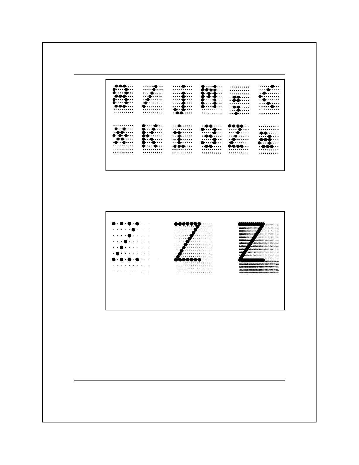
typical dot-matrix characters
Quality can be improved by increasing the dot density (resolution),
as shown in the following figure. Dot density is expressed in dots per
inch (dpi).
low-resolution
character
medium-resolution
character
high-resolution
character
effect of increasing dot density
The Model 8900 Series Printer offers four levels of print quality,
based on the dot density and the placement of dots on the matrix.
The increased dot density at higher print-quality levels decreases the
print speed.
General Information 1-5
Page 13

The printer offers the following print-quality levels and speeds.
q Letter quality (LQ) — high-resolution, 32-dot by 18-dot characters
at 100 characters per second (cps).
q Text quality — medium-resolution, 15-dot by 9-dot characters at
240 cps.
q Normal draft quality — low-resolution, 9-dot by 9-dot characters
at 400 cps.
q Rapid Print draft quality — low-resolution, 7-dot by 9-dot
characters. This mode is only valid for character spacings
(pitches) of 12 characters per inch (cpi) and 15 cpi. These
character pitches allow the printer to print at speeds of 480 cps
and 600 cps, respectively.
Raster Graphics
The all-points-addressable raster graphics mode lets you use your
printer to produce pictorial material, such as charts, graphs, special
characters, or almost any design you can devise. Special commands
allow you to design images of any shape by causing the printhead to
print dots in the appropriate places. (See Chapters 4 through 8 for
information about raster graphics commands.)
The best way to print graphics is to use one of the many commercially
available application programs. These programs let you design
images by drawing them on your computer monitor and then issuing
a command to send them to your printer.
General Information 1-6
Page 14

2
Printer Setup
Introduction .................................................................................... 2-3
Model 8900 Series Emulation Modes ............................................ 2-5
TI 880 Emulation....................................................................... 2-6
Execute Commands .............................................................. 2-6
Line Feed and Carriage Return Upon Receipt of LF............ 2-6
Line Feed and Carriage Return Upon Receipt of CR ........... 2-7
Carriage Return Upon Receipt of LF, VT, or DC2............... 2-7
Graphics................................................................................ 2-7
Shift Out Equals Expanded Print.......................................... 2-7
TI 855 Emulation....................................................................... 2-8
Processing Mode................................................................... 2-8
Automatic Line Feed ............................................................ 2-8
IBM Proprinter XL and Epson FX Emulations ......................... 2-8
Automatic Line Feed ............................................................ 2-8
Automatic Carriage Return................................................... 2-9
Slashed Zeros........................................................................ 2-9
Hexadecimal Dump Mode......................................................... 2-9
Interface Parameters ................................................................ 2-10
Port .......................................................................................... 2-10
Buffer Size............................................................................... 2-10
Baud Rate ................................................................................ 2-11
Data Bits .................................................................................. 2-11
Parity ....................................................................................... 2-11
Flow Control............................................................................ 2-11
XON/XOFF (transmit-on/transmit-off)................................... 2-12
Robust XON/XOFF................................................................. 2-12
ETX/ACK (end-of-text/acknowledge) ............................... 2-13
Connection............................................................................... 2-13
DTR (Pin 20) ...................................................................... 2-13
PIN 11 ................................................................................. 2-13
Printer Setup 2-1
Page 15

Miscellaneous Setup Parameters .................................................. 2-14
Character Set ........................................................................... 2-14
Z-Axis Control......................................................................... 2-15
Ribbon Type ............................................................................ 2-15
Ribbon Adjust.......................................................................... 2-15
Idle Delay................................................................................. 2-16
Power-Up Online ..................................................................... 2-16
Paper Pull-Down Warning ....................................................... 2-16
Graphics Printing Mode ......................................................... 2-17
LCD Language......................................................................... 2-17
Paper Out Equals Busy ............................................................ 2-17
Limiting Control Panel Operation ........................................... 2-17
Test Features ................................................................................. 2-18
Printer Setup 2-2
Page 16
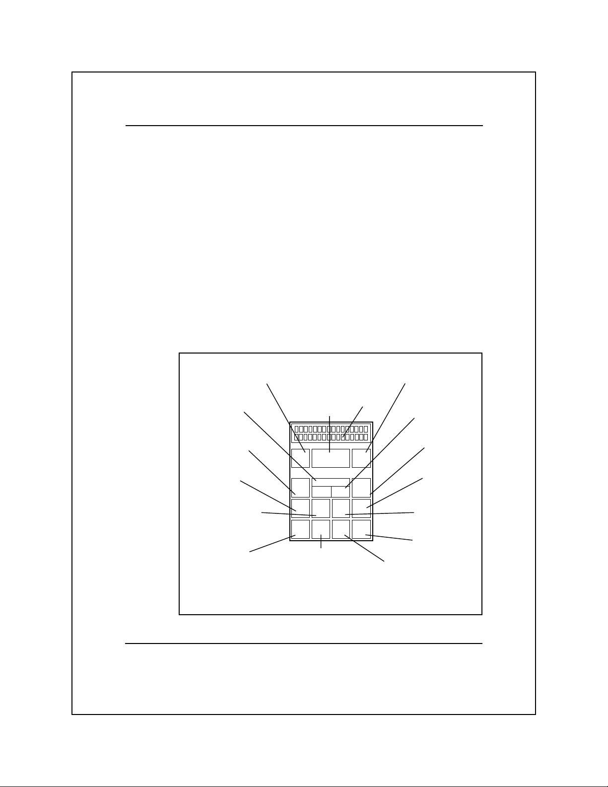
Introduction
The Model 8900 Series Printers are compatible with a wide range of
computers and application software. The printer menu structure
enables you to select and alter the fundamental printer operating
parameters to fit the requirements of your computer, its communication
interface, and its application software. You can set these parameters
via the operator control panel (see the following figure).
To set up the printer, you set the various printer parameters to meet
the requirements of your computer system. (Refer to your computer
operator’s manual for more information.) After you set the parameters
to the required values, the printer stores these settings in its nonvolatile
random-access memory (NVRAM). Because the NVRAM retains
information even when the printer is without power, the printer
retains these settings until you change them.
function switch associated with messages
and symbols shown at the left end of the
display (loads form on 8930)
selects one of ten preset
form formats or forms
settings report
allows you to select the
primary paper path or an
alternate paper path
selects one of four
character spacing
choices
selects one of three print
quality choices
allows you to get a report
of current printer settings,
test basic printer
functions, and change
printer features
F1
Paper
Path
Pitch
Setup/
Test
causes the display to
show a brief summary
of printer status and
current printer settings
operator control panel
select items
shown on the
display (loads
form on 8920)
Form
Config.
Select
Quality Font Clear
Status Form
Align
function switch associated with
messages and symbols shown at the
display
F2Select
On Line
Error
Form
Feed
which lets you move the paper up
right end of the display
allows you to change
form format values
selects online or
offline operation
clears error messages
from the display
selects one of the
standard fonts or an
optional font
advances paper to the
top of the next form
invokes the form align screen
or down in the print station
Printer Setup 2-3
Page 17
Note: The Model 8900 Series Printers User’s Manual (Part No.
2557785-0002) explains the basic use of the operator control panel
and its associated menu structure.
The Setup/Test switch on the control panel lets you enter the setup/
test menu. This menu consists of the following submenus containing
most of the printer setup parameters and test features.
q Emulation mode — The emulation mode submenu lets you
select an emulation mode and set its parameters. This submenu
also lets you select the hexadecimal dump mode.
q Interface parameters — The interface parameters submenu lets
you set the serial communication parameters to the values
required by the host computer and by the communication interface.
q Miscellaneous parameters — The miscellaneous parameters
submenu lets you select various printer features, both standard
and optional.
q Test mode — The test mode submenu lets you select the printer
test features.
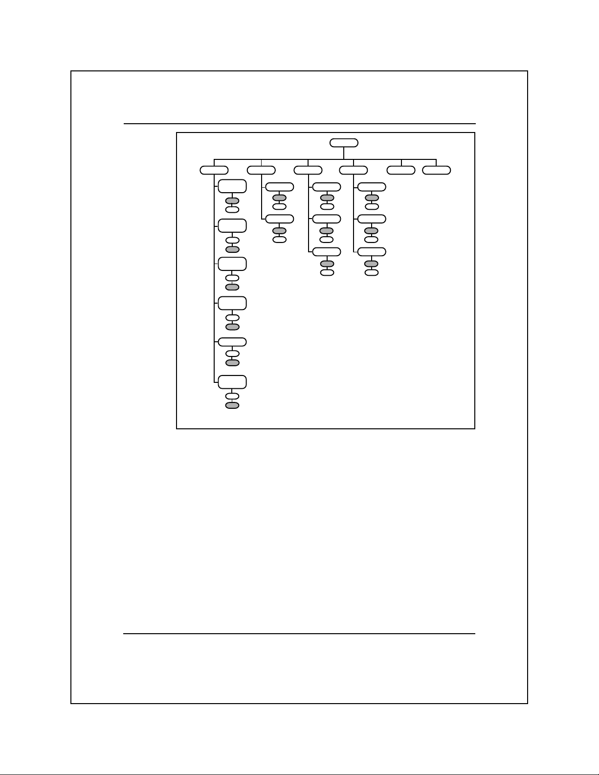
The following figure shows the setup/test menu and the following
paragraphs describe the setup/test submenus.
Setup/
Test
Emulation
setup/test menu
Interface Misc Test Mode
Printer Setup 2-4
Page 18

Model 8900 Series Emulation Modes
The emulation mode determines how the printer responds to commands
from the host computer and determines the specific set of commands
to which the printer responds. For example, if you select the TI 880
emulation mode, the printer emulates the functions of the TI Model
880 Printer and responds to the set of commands designed for that
printer.
The emulation mode submenu lets you choose one of the following
emulation modes or select the hexadecimal dump mode.
q TI Model 880 printer (default)
q TI Model 855 printer
q IBM Proprinter XL
q Epson FX printer
q Optional
q Hexadecimal dump
Chapters 4 through 8 of this manual describe these emulation modes
and their functions. The emulation mode you choose must be
compatible with the host computer and its currently installed software.
The following figure shows the emulation mode submenu and the
following paragraphs describe the emulation mode setup parameters.
Printer Setup 2-5
Page 19
Execute
Commands
ON
OFF
LF/CR
ON LF
OFF
OFF
LF/CR
ON CR
ON
OFF
CR W/LF
VT DC2
ON
OFF
Graphics
ON
OFF
SO=
Expand
ON
OFF
Proc Mode Auto LF Auto LF
DP
WP
Auto LF Auto CR
NO
YES
emulation mode submenu
Emulation
ProPrinterTI855TI880 Epson optional Hexdump
NO
YES
NO
YES
Slashed 0’s
NO NO
YES
NO
YES
Auto CR
NO
YES
Slashed 0’s
YES
TI 880 Emulation
The TI 880 emulation submenu contains a group of setup parameters
that can be set to either on or off. These parameters determine how
your printer responds to certain commands from the host computer.
Execute Commands
When on, this parameter enables the printer to respond to escape
sequence commands from the host computer. The default setting is ON.
Line Feed and Carriage Return Upon Receipt of LF
When on, this parameter causes the printer to perform both a line
feed (LF) operation and a carriage return (CR) operation upon
receiving an LF command from the host computer. The default
setting is OFF.
Printer Setup 2-6
Page 20

Line Feed and Carriage Return Upon Receipt of CR
When on, this parameter causes the printer to perform both an LF
operation and a CR operation upon receiving a CR command from
the host computer. The default setting is OFF.
Carriage Return Upon Receipt of LF, VT, or DC2
When on, this parameter causes the printer to perform a CR operation
upon receiving any of the following commands.
q Line feed (LF) — The printer moves the printhead down to the
next print line and returns the carriage to the left margin.
q Vertical tabulation (VT) — The printer prints the remainder of
the current print line, moves the printhead down to the next
vertical tab stop, and returns the carriage to the left margin.
q Device control 2 (DC2) — The printer moves the printhead
down to the print line specified by the DC2 n (Move to Line n)
command and returns the printhead to the left margin.
The default setting for the parameter CR W/LF VT DC2 is OFF.
Graphics
When on, this parameter enables the raster graphics escape sequences
described in Chapter 4. The default setting is OFF.
Shift Out Equals Expanded Print
When on, this parameter causes the printer to print one line of
expanded print after receiving a shift out (SO) command. When this
parameter is off, the printer invokes the G1 character set into the GL
area of the character table upon receiving SO. The default setting is
OFF.
Printer Setup 2-7
Page 21

TI 855 Emulation
The TI 855 emulation submenu contains the processing mode (WP/DP)
parameter and the automatic line feed parameter, both of which can
be set to match the requirements of your computer. The following
paragraphs describe these parameters.
Processing Mode
The Tl 855 emulation mode lets you choose either of the following
processing modes.
q DP mode — uses commands (described in Chapter 6) similar to
those used by a dot-matrix-type printer.
q WP mode — uses commands (described in Chapter 5) similar to
those used by a daisy-wheel printer.
The default setting for the processing mode parameter is DP.
Automatic Line Feed
Some software programs send both a CR command and an LF command
at the end of each print line, while others send only a CR command.
For software that sends only a CR command at the end of each print
line, the printer needs to perform an LF operation automatically. The
default setting for the automatic LF parameter is NO.
IBM Proprinter XL and Epson FX Emulations
The IBM Proprinter XL and Epson FX emulation submenus contain
the same following parameters.
Automatic Line Feed
This parameter is identical to the automatic LF parameter described
for the TI 855 emulation mode. The default setting is NO.
Printer Setup 2-8
Page 22
Automatic Carriage Return
This parameter is similar to the automatic LF parameter but is turned
on for software that does not send a CR command at the end of each
print line. If the printer advances from print line to print line but fails
to perform a carriage return operation, you need to turn on the
automatic CR parameter. The default setting is NO.
Slashed Zeros
When on, this parameter causes the printer to print slashes over all
zeros to distinguish them from the letter O. The default setting is NO.
Hexadecimal Dump Mode
The hexadecimal dump (HEXDUMP) mode causes the printer to
print the ASCII (hexadecimal) codes for all text characters, control
characters, and escape-sequence commands it receives. The resulting
printout can be useful as a troubleshooting device or in analyzing a
block of data and commands sent from the host computer.
The printer does not respond to any control characters or commands
except when the printer is using the serial or option port and FLOW
CONTROL is set to ETX/ACK; in such a case, the printer interprets
and responds to an ETX control character as an end-of-text command.
The ETX character is also included as part of the hex dump.
Note: Chapter 3 describes ASCII codes and control characters;
Chapters 5 and 6 describe the escape-sequence commands for the
TI 855 emulation mode.
Printer Setup 2-9
Page 23
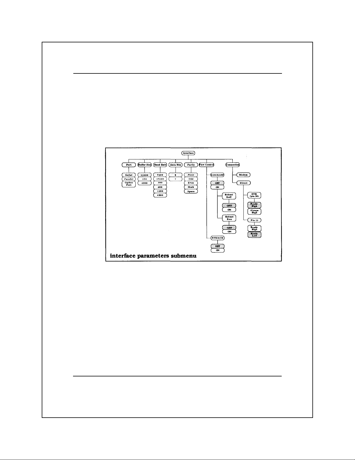
Interface Parameters
The interface parameters are values associated with serial communication interfaces. When using a serial interface, these parameters
must be set to correspond to the capabilities of the host computer and
the interface.
The following figure shows the interface submenu and the following
paragraphs describe the interface setup parameters.
Port
The port submenu lets you choose the correct communication
interface port, depending on whether you are using a serial, parallel,
or optional interface. The default setting is SERIAL.
Buffer Size
The buffer size specifies the number of data bytes that the printer’s
receive buffer can store. The buffer size parameter can be set to 256,
4000, or 32,000 bytes. The default setting is 32,000.
Printer Setup 2-10
Page 24
Baud Rate
The baud rate is the rate (in bits per second) at which the interface
transfers data. This parameters are 300, 600, 1200, 2400, 4800, 9600,
or 19,200 bits per second. The default setting is 9600.
Note: Data transferred over a serial interface consists of either 7- or
8-bit data bytes, each of which is accompanied by a start bit, a stop
bit, and a parity bit. The values chosen for the data bits and parity
parameters depend upon the requirements of the host. (See Chapters
3 and 10.)
Data Bits
The data bits parameter specifies whether the printer is to print 7- or
8-bit character codes. The default setting is 8. (Refer to Chapters 3
and 10 for information about 7- and 8-bit data.)
Parity
Parity checking (often called simply parity) is a method of verifying
that data is not changed in the transfer process. This parameters are
None, Odd, Even, Mark, or Space, depending upon the requirements
and capabilities of your computer. The default setting is NONE. If
the parity bit is selected, it is in addition to the 7 or 8 data bits.
Flow Control
To ensure the orderly flow of data between the host and printer, the
host computer establishes a set of rules commonly known as the
ready/busy protocol. This protocol allows the printer to notify the
host that it is either ready to receive data or that it is busy and cannot
receive data. The following paragraphs describe the flow-control
parameters.
Printer Setup 2-11
Page 25
XON/XOFF (transmit-on/transmit-off)
For this busy-handling protocol, the printer sends a single XON (a
DC1 control character) to indicate that it is ready to receive data and
a single XOFF (a DC3 control character) to indicate that it is busy.
The default setting is OFF.
Robust XON/XOFF
For the robust XON/XOFF protocol, the printer sends an XON (DC1
control character) approximately every 5 seconds to indicate that it is
ready to receive data until either data is received or another busy
condition occurs. The printer sends an XOFF (DC3 control character)
when the initial busy condition occurs (buffer overflow) to indicate
that it is busy. If the host continues to send data, the printer sends an
XOFF approximately every 20 ms until the hosts stops sending data.
The default setting is OFF.
The following table lists the ready and busy points using the
XON/XOFF protocol.
LCD Display of Busy Point Ready Point
Buffer Size From Empty After Busy
32,000 @ 32,000 Bytes @ 31,250 Bytes
4,000 @ 4,000 Bytes @ 3,250 Bytes
256 @ 256 Bytes @ 128 Bytes
Note: Actual buffer size is 32,768 bytes; overflow error status only
occurs after 32,768 bytes.
Printer Setup 2-12
Page 26

ETX/ACK (end-of-text/acknowledge)
For this busy-handling protocol, the host sends an ETX control
character at the end of each data transmission, and the printer
responds with an ACK control character to indicate that it is ready to
receive additional data. If the printer is busy when it receives the
ETX control character, it delays sending the ACK control character
until the busy condition is cleared. The default setting is OFF.
Connection
This feature provides selections for use when connecting the printer
directly to the host computer or indirectly via a modem. When you
connect the printer to a modem, set the connection parameter to
MODEM. When you connect the printer directly to the host computer
or a terminal, select DIRECT and set the busy-handling parameters
to conform to the requirements of the computer. The default setting
is DIRECT. The following paragraphs describe the direct connection,
ready/busy protocol.
DTR (Pin 20)
For this parameter you can choose either READY HIGH or AL WAYS
HIGH. For the READY HIGH setting, the printer sets interface pin
20 high to indicate that it is ready to receive data and low to indicate
that it is busy. For the ALWAYS HIGH setting, pin 20 is not used for
busy notification; one of the other busy-handling options must be
chosen. The default setting is READY HIGH.
PIN 11
For this parameter, you can choose either READY HIGH or READY
LOW. For the READY HIGH setting, the printer sets interface pin 11
high to indicate that it is ready to receive data and low to indicate
that it is busy. For the READY LOW setting the printer sets interface
pin 11 low to indicate that it is ready to receive data and high to
indicate that it is busy. The default setting is READY LOW.
Printer Setup 2-13
Page 27
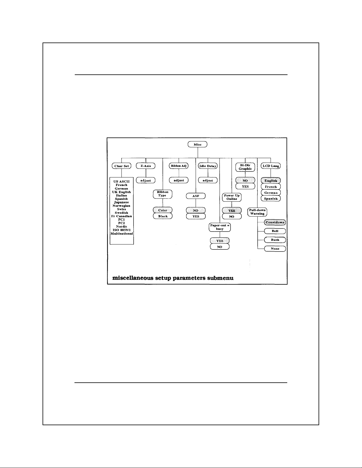
Miscellaneous Setup Parameters
The miscellaneous setup parameters are mechanical and operational
features that do not fit logically into the other setup categories.
The following figure shows the miscellaneous setup parameters
submenu and the following paragraphs describe these parameters.
Character Set
The Model 8900 Series Printers character set repertoire includes 6
standard character sets and 11 international language versions. The
default character set is IBM PC1 and the default international
language version is U.S. English.
Printer Setup 2-14
Page 28

Z
-Axis Control
The printer adjusts the printhead-to-paper clearance (z-axis) automatically when you load paper into the printer. In addition, the Z-AXIS
parameter provides a manual z-axis adjustment. This selection
invokes a display that lets you adjust the printhead in or out.
You also can adjust the z-axis using an escape sequence described in
the Appendix to this manual.
Ribbon T ype
The RIBBON TYPE parameter lets you choose between color
printing and black printing. The default setting is COLOR.
Ribbon Adjust
If the printer appears to be printing mixed colors or missing the upper
or lower parts of the characters, the ribbon may need adjustment.
The RIBBON ADJ parameter invokes a display that lets you adjust
the ribbon up or down.
Printer Setup 2-15
Page 29

Idle Delay
At the end of a printing operation, if the paper is at top of form, the
printer waits for more data and then, after a short delay (idle delay),
moves the paper to the tear-off position. The IDLE DELAY parameter
invokes a display that lets you adjust the idle delay to a value in the
range of 300 milliseconds to 90 seconds.
You can disable the idle delay feature by selecting a value above 90
seconds, in which case the LCD displays DISABLE. When you
disable this feature, the printhead “relaxes” (moves away from the
paper) after 91 seconds of idle time and the paper is not moved to the
tear-off position.
Power-Up Online
The PWRUP ONLINE parameter lets you set the printer to power-up
in either its online or offline condition. The default setting is YES
(power-up online).
Paper Pull-Down Warning
This parameter lets you select the type of warning that occurs when
the printer is about to pull down tractor-fed paper from its tear-off
position to the normal printing position.
The COUNTDOWN option (factory default) causes the printer LCD
to display the numerals 9, 8, 7... down to 1, visually warning that
paper pull-down is imminent. The pull-down time delay is increased
about 3 to 4 seconds.
The BELL option causes a series of nine beeps of increasing duration
to indicate paper pull-down. The pull-down time delay is increased
about 3 to 4 seconds.
The BOTH option causes the COUNTDOWN and BELL options to
occur simultaneously.
The NONE option turns off the pull-down warning.
Printer Setup 2-16
Page 30

Graphics Printing Mode
The BI-DIR GRAPHIC parameter lets you choose whether the
printer prints graphics bidirectionally or from left to right only. The
default setting is NO (print graphics from left to right only).
LCD Language
The LCD LANG parameter lets you set the control panel LCD to
display its messages in English, French, German, or Spanish. The
default setting is ENGLISH.
Paper Out Equals Busy
The PAPER OUT = BUSY parameter, when set to YES, lets the
printer send a busy condition signal to the communication interface
when the printer runs out of paper. The default setting is YES.
Limiting Control Panel Operation
This parameter enables you to select three levels of control panel
functioning, intended to limit operator access to certain printer
function. This effectively prevents operator error resulting from
incorrect control panel operation. The menu offers four choices from
Level 0 (factory default) to Level 3.
Level 0 is conventional, full control panel operation.
Level 1 permits full offline control panel operation, but when the
printer is online only the Online and Clear Error keys function.
Level 2 limits online operation to the Online and Clear Error keys
and, when offline, disables the Form Config, Pitch, Quality, Font,
and Setup/Test keys.
Level 3 limits online operation to the Online and Clear Error keys
and, when offline, disables the Form Select, Form Config, Pitch,
Quality, Font, and Setup/Test, and Form Feed keys.
Printer Setup 2-17
Page 31

Access the menu to select the four available options as follows.
1. Press and hold the Clear Error switch, then press and hold the
Status switch.
2. Release the Clear Error switch, continue to hold the Status
switch, then press and hold the Setup/Test switch.
3. Release the Status switch, continue to hold the Setup/Test
switch. The LCD displays Key Access.
4. Press the F2 switch until the level you want is displayed, then
press the On Line switch to return the printer to its previous
mode.
Test Features
The test mode submenu lets you use the built-in printer test
features. The Model 8900 Series Printers User’s Manual, Part No.
2557785-0001, describes the status report and the barberpole test.
Clear
Error
press & hold press & hold
▲
Status
limiting control panel operation menu
▲
Setup/
Test
Key
Access
Level 0
Level 1
Level 2
Level 3
Printer Setup 2-18
Page 32

3
Character Sets and Global Commands
Introduction .................................................................................... 3-2
Character Code Table ..................................................................... 3-2
Character Sets................................................................................. 3-3
The US ASCII Character Set..................................................... 3-3
International ASCII Character Sets ........................................... 3-5
The IBM PC1 Character Set...................................................... 3-6
The IBM PC2 Character Set...................................................... 3-8
The Nordic PC Character Set .................................................. 3-10
ISO 8859/1 Multinational Character Set ................................. 3-12
IBM Multinational Character Set ............................................ 3-14
Control Characters........................................................................ 3-16
Printer Commands ........................................................................ 3-19
Global Command Set.................................................................... 3-20
Global Command Descriptions .................................................... 3-20
Barcode Operations ................................................................. 3-21
Set Barcode Parameters ...................................................... 3-21
Print Barcode Text .............................................................. 3-22
Oversize Characters Feature.................................................... 3-22
Set Oversize Character Scale Factor .................................. 3-22
Print Oversize Character..................................................... 3-22
Color Printing .......................................................................... 3-23
Selecting an Automatic Sheet Feeder Bin ............................... 3-24
Selecting a Form Format ......................................................... 3-24
Defining Raster Graphics ........................................................ 3-25
Selecting a Font’s HMI............................................................ 3-25
Selecting Characters Per Inch (cpi) ......................................... 3-26
Selecting Print Quality ............................................................ 3-26
Selecting an International Character Set ................................. 3-27
Selecting an Emulator.............................................................. 3-28
Adjusting the Printhead Z-Axis Position................................. 3-29
Writing to the Printer Display ................................................. 3-29
Paper-Handling Operations ..................................................... 3-29
Character Sets and Global Commands 3-1
Page 33
Introduction
This chapter describes the standard character sets and provides
information about their use in the Model 8900 Series Printers.
The printer can use any of several standard or optional character sets
that can be selected via the operator control panel switches or via the
host computer. These character sets provide all control characters
and graphic characters necessary to implement the various printer
emulation modes.
The standard character sets reside in the printer read-only memory
(ROM), and the optional character sets can be plugged into one of
the option ROM sockets on the printer logic board.
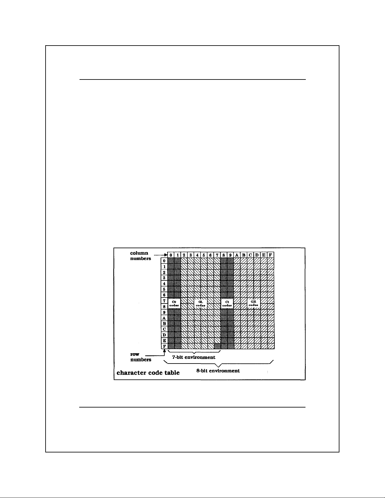
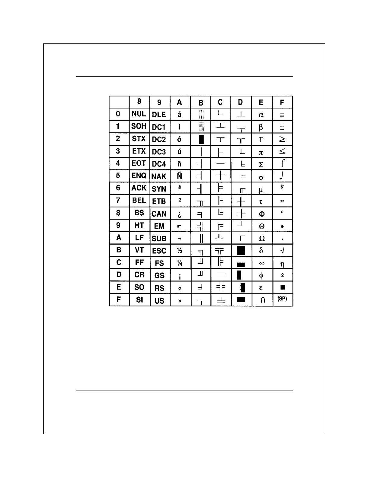
Character Code Table
The following figure shows the printer character code table. The
character code table is an area in the printer memory in which one
8-bit character set or two 7-bit character sets reside.
Character Sets and Global Commands 3-2
Page 34

Character Sets
Your printer can use any of the following character sets.
q US ASCII (default character set)
q IBM PC1
q IBM PC2
q Nordic PC
q ISO 8859/1 Multinational
q IBM Multinational
Note: The option ROM sockets on the printer logic board let you
install additional character sets.
Character Sets and Global Commands 3-3
Page 35

The US ASCII Character Set
The following table shows the U.S.A. Standard Code for Information
Interchange (US ASCII) character set. This 7-bit character set is
defined by the American National Standards Institute document
ANSI X3.4 and is a variant of the ISO 646 character set.
US ASCII Character Set
Character Sets and Global Commands 3-4
Page 36

International ASCII Character Sets
With a few exceptions, the international versions of the ASCII
character set are identical to the US ASCII character set. These
international versions can be selected via the operator control panel
or via the host computer. The following table lists the variations
between the US ASCII character set and the international versions.
Variations Between US ASCII and International ASCII
Character Sets and Global Commands 3-5
Page 37

The IBM PC1 Character Set
The following two tables show, respectively, the left half and right
half of the the IBM PC 1 character set.
IBM PC1 Character Set, Left Half
Character Sets and Global Commands 3-6
Page 38
IBM PC1 Character Set, Right Half
Character Sets and Global Commands 3-7
Page 39

The IBM PC2 Character Set
The following two tables show, respectively, the left half and the
right half of the IBM PC2 character set.
IBM PC2 Character Set, Left Half
Character Sets and Global Commands 3-8
Page 40

IBM PC2 Character Set, Right Half
Character Sets and Global Commands 3-9
Page 41

The Nordic PC Character Set
The following two tables show, respectively, the left half and right
half of the Nordic PC character set.
Nordic PC Character Set, Left Half
Character Sets and Global Commands 3-10
Page 42

Nordic PC Character Set, Right Half
Character Sets and Global Commands 3-11
Page 43

ISO 8859/1 Multinational Character Set
The following two tables show, respectively, the left half and right
half of the ISO 8859/1 Multinational character set. The shaded
character positions (128-159) represent the Cl control characters
which are not implemented in the Model 8900 Series Printers.
ISO 8859/1 Multinational Character Set, Left Half
Character Sets and Global Commands 3-12
Page 44

ISO 8859/1 Multinational Character Set, Right Half
Character Sets and Global Commands 3-13
Page 45

IBM Multinational Character Set
The following two tables show, respectively, the left half and right
half of the IBM Multinational character set.
IBM Multinational Character Set, Left Half
Character Sets and Global Commands 3-14
Page 46
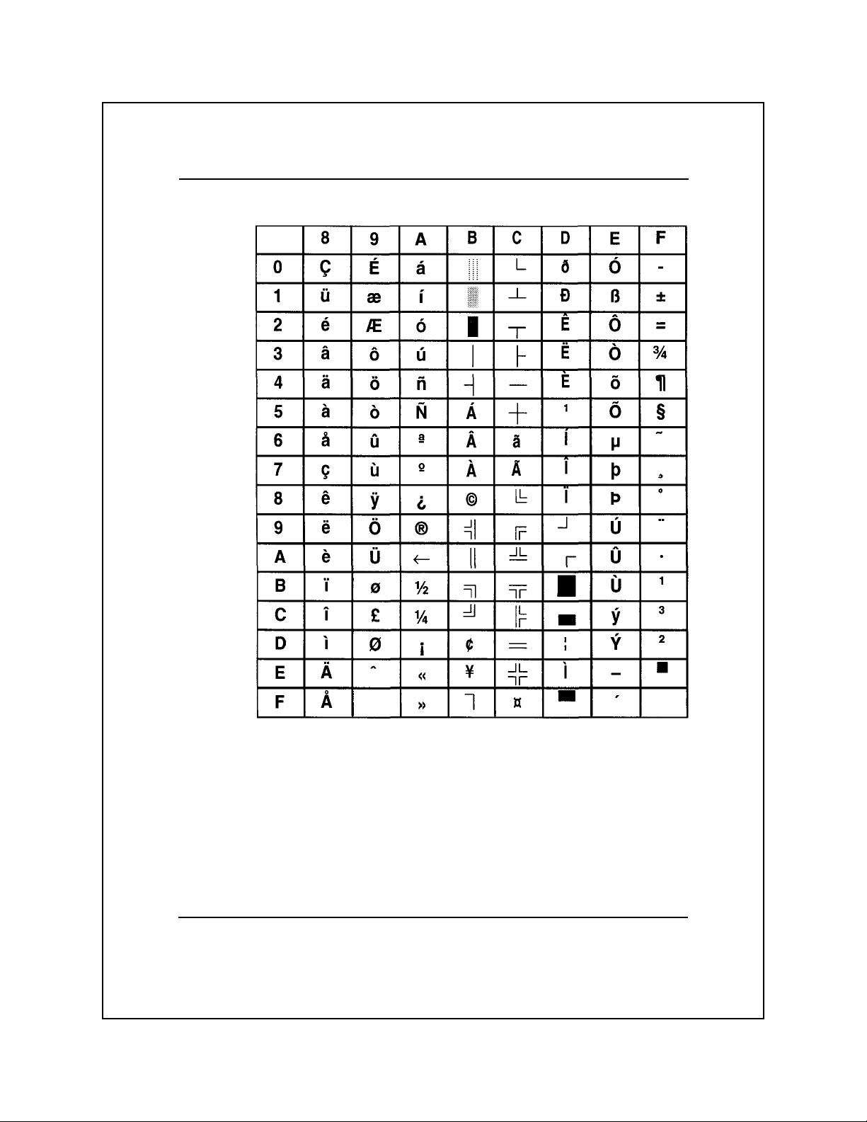
IBM Multinational Character Set, Right Half
Character Sets and Global Commands 3-15
Page 47

Control Characters
Any character that causes the printer to perform a function is classified
as a control character. Note that, although the Cl control characters are
available in one of the standard character sets (ISO 8859/Multinational),
your printer does not implement them.
American National Standard ANSI X3.4 and International Standard
ISO 646 define the C0 control characters based on the specific
function performed by the character. The C0 control characters are
divided into the following categories.
q Communication controls - Control characters intended to control
or enable data transmissions over communication networks.
q Format effectors - Control characters that control the layout or
position of information on the printed page.
q Information separators - Control characters that separate and
qualify information in a logical sense.
q Miscellaneous control characters - Control characters whose
definitions preclude their inclusion in the preceding categories.
The following table lists and defines the original use of the C0
control characters.
Note: The functions of the control characters can vary from one
emulation mode to another. Therefore, these descriptions are included
in Chapters 4 through 9.
Character Sets and Global Commands 3-16
Page 48

C0 Control Characters
Char Code Definition
Communication controls:
SOH 01 Start of header
STX 02 Start of text
ETX 03 End of text
EOT 04 End of transmission
ENQ 05 Enquiry
ACK 06 Acknowledge
DLE 10 Data link escape
NAK 15 Negative acknowledge
SYN 16 Synchronous idle
ETB 17 End of transmission block
Format effectors:
BS 08 Backspace
HT 09 Horizontal tabulation
LF 0A Line feed
VT 0B Vertical tabulation
FF 0C Form feed
CR 0D Carriage return
FS 1C File Separator
Information separators:
GS 1D Group separator
RS 1E Record separator
US 1F Unit separator
Miscellaneous controls:
NUL 00 Null
BEL 07 Bell
SO 0E Shift out
SI 0F Shift in
DC1 11 Device control 1
DC2 12 Device control 2
DC3 13 Device control 3
DC4 14 Device control 4
CAN 18 Cancel
EM 19 End of medium
SUB 1A Substitute
ESC 1B Escape
DEL 7F Delete
Hexadecimal
Character Sets and Global Commands 3-17
Page 49

Printer Commands
The Model 8900 Series Printers receive commands from the host
computer in the form of ASCII control character codes and escapesequence codes. In response to these commands, the printer performs
one or more operations defined by the command set of the currently
selected emulation mode. Chapters 4 through 8 describe the standard
emulation modes.
An example of a control character command common to all character
sets and all emulation modes is the line feed (LF) character. This
control character (designated by hexadecimal code 0A or decimal
code 10) causes the printer to advance the paper or form to the next
print line. To invoke the line feed operation, the host computer sends
the 8-bit code (00001010) identified as the LF character.
An escape-sequence command is a sequence of two or more characters
that always begins with the ASCII escape (ESC) control character
designated by hexadecimal code 1B. The ESC control character
signals the printer that one or more succeeding characters are an
escape-sequence command.
An example of an escape-sequence command common to all standard
emulation modes is the Set Form Length command ESC C n. This
command contains the following elements.
q ESC — the ASCII control character that signals the start of an
escape sequence
q C — an ASCII character that identifies the escape sequence as a
form length command
q n — a decimal variable that can be set to a range of values to
specify the form length in number lines
Note: Decimal values of variables are designated by lowercase italic
letters. ASCII characters and number values of variables are
designated by uppercase italic letters.
Character Sets and Global Commands 3-18
Page 50

Some escape sequence commands, valid for all emulation modes, are
called global commands. These are special commands that select or
control some basic or specially defined printer operation.
Global Command Set
The following table lists the global commands for the Model 8900
Series Printers. These commands are characterized by an intermediate
control character DLE following the ESC character.
Model 8900 Series Printers Global Commands
Command Command Name
ESC DLE B P t r s ETX Set Barcode Parameters
ESC DLE B C text ETX Print Barcode Text
ESC DLE C C text ETX Print Oversize Characters
ESC DLE C P p1 p2 ETX Set Oversize Characters Scale Factor
ESC DLE c n Select Color Printing
ESC DLE E text ETX Select Emulator
ESC DLE EM n Select Automatic Sheet Feeder Bin
ESC DLE F x Select Form Format
ESC DLE G d1 d2 n1 n2 data Define Raster Graphics
ESC DLE f n Select font
ESC DLE H Select Font HMI
ESC DLE P n Select Characters Per Inch (cpi)
ESC DLE p 0 Load from Current Paper Path
ESC DLE p 1 Park Continuous Paper
ESC DLE p 2 Load Cut-Sheet Paper from Front
ESC DLE p 3 Load Continuous Paper
ESC DLE p 4 Load Cut-Sheet Paper from Top
ESC DLE Q n Select Print Quality
ESC DLE R n Select International Character Set
ESC DLE STX text ETX Write to Printer Display
ESC DLE z S NN Adjust Printhead Z-axis Position
Global Command Descriptions
The following paragraphs describe the Model 8900 Series Printers
global commands.
Character Sets and Global Commands 3-19
Page 51

Barcode Operations
The barcode commands let you select a barcode font, set its
parameters, and print any specified character in the equivalent
barcode font.
Note: If the barcode option is not installed, using this ESC sequence
causes an ESC SEQ error.
Set Barcode Parameters
Escape sequence: ESC DLE B P trsETX
Hexadecimal: 1B 10 42 50 trs03
This command, where t = type, r = readability, and s = size, lets you
select a barcode font and set its associated parameters. The following
values are valid for the command variables.
q Type:
0 — Barcode 3 of 9 (default)
1 — Interleaved 2 of 5
3 — Codabar
q Readability:
0 — Not human readable (default)
1 — Human readable characters on top
2 — Human readable characters on bottom
3 — Human readable characters on top and bottom
q Size:
Vertical height in 8/72 inch increments (default 8/72")
Note: PostNet barcode is available as a font; see “Selecting a Font.”
Character Sets and Global Commands 3-20
Page 52

Print Barcode Text
Escape sequence: ESC DLE B C text ETX
Hexadecimal: 1B 10 42 43 text 03
This command lets you print a character or string of characters
specified by the variable text. For example, to print the barcode
equivalents of the numerals 0, 1, and 2 from the barcode font set
selected by the Set Barcode Parameters command, enter the sequence
ESC DLE B C 0 1 2 ETX.
Oversize Characters Feature
Using this feature, you can increase the size of your selected font
from 1 times to 127 times the original size. One global command
determines the character size; a second global command prints the
oversize characters.
Set Oversize Character Scale Factor
Escape sequence: ESC DLE C P p1 p2 ETX
Hexadecimal: 1B 10 43 50 p1 p2 03
This command defines the horizontal and vertical scale factors which
determine the size of the characters printed by the Print Oversize
Character command.
The p1 variable is the vertical scale factor (1 byte), from 1 to 127;
the default is 2. The p2 variable is the horizontal scale factor (1 byte),
from 1 to 127; the default is 2. If either variable is set to less than 1
or more than 127, the value defaults to 2.
Character Sets and Global Commands 3-21
Page 53

Print Oversize Character
Escape sequence: ESC DLE C C text ETX
Hexadecimal: 1B 10 43 43 text 03
This command prints the text contained within the command using
the horizontal and vertical scale factors selected by the Set Oversize
Characters command. The text variable is the character string to be
printed in oversize characters.
You can use a maximum of 200 characters in a text string; excess
characters are treated as normal characters, and the command is
limited to printing from the logical start position to the logical end
position of a single line of text. Text extending beyond the end of the
line is truncated at the logical end position.
Because the ETX control character is used as the command sequence
delimiter, if your text string requires an ETX character you must use
two consecutive ETX characters within the text string to be recognized.
The printer uses the bit patterns dictated by the print quality selected;
draft quality bit patterns in draft mode, text quality bit patterns in
text and quality modes.
Color Printing
Escape sequence: ESC DLE c n
Hexadecimal: 1B 10 63 n
The Model 8900 Series Printers can print up to seven different colors
(including black). This feature is standard on the Model 8930 and
optional on the Model 8920.
This command selects the color specified by the variable n, where n
can be any of the following values.
0 — black 4 — green
1 — cyan 5 — purple
2 — magenta 6 — orange
3 — yellow
Character Sets and Global Commands 3-22
Page 54

Selecting an Automatic Sheet Feeder Bin
Escape sequence: ESC DLE EM n
Hexadecimal: 1B 10 19 n
This command selects the ASF bin designated by the variable n,
where n can range from 30 through 33 hex as follows:
0 (30H) = Load from current bin
1 (31H) = Select & load from bin 1
2 (32H) = Select & load from bin 2
3 (33H) = Load from current bin
If the command is received with paper loaded from a friction feed
path, the currently loaded form is ejected, and a form is loaded as
defined by this command. If the command is received with paper
loaded from the tractor feed path, this command is accepted but
ignored.
The ASF option on the Miscellaneous Menu of the printer control
panel must be set to “YES” for this function to operate.
Selecting a Form Format
Escape sequence: ESC DLE F x
Hexadecimal: 1B 10 46 x
The Model 8900 Series Printers offer a set of ten predefined form
formats. Each of these form formats, designated as A through J, has an
associated set of values that defines the parameters of the form. Although
these form format parameters are preset at the factory to their default
values, the user can select any of the form formats and alter its
parameters to fit any specific application. The Model 8900 Series
Printers User’s Manual, Part No. 2557785-0002, describes the preset
form format parameters and explains how to select and change them.
The Select Form Format command selects the form format designated
by the variable x, where the value of x can be any of the ten predefined
form formats A through J.
Character Sets and Global Commands 3-23
Page 55

Defining Raster Graphics
Escape sequence: ESC DLE G d1 d2 n1 n2 data
Hexadecimal: 1B 10 47 d1 d2 n1 n2 data
This command defines the dots-per-inch (DPI) density, the byte
count of bit-image data, and bit-image data of those emulations that
currently support raster graphics.
The variable d1 d2 is DPI density, where d1 is LSB and d2 is MSB.
The variable nl n2 is the byte count, where n1 is the LSB and n2 is
the MSB. And data is bit-image data. All variables can range from 0
through 255.
DPI density defines the horizontal dots per inch at which the bit
image data is printed. Valid DPI values are 60, 72, 80, 90, 100, 120,
135, 144, 150, 180, 200, 240, and 300 dots per inch. Any other value
causes an escape sequence error. The DPI density format is d1 + (d2
* 256) = DPI.
The byte count variable indicates the number of bit-image data bytes
to follow. The byte count format is n1 + (n2 * 256) = byte count.
A bit-image data byte defines a column of 8-pin raster graphics. The
bits of each byte have valid values of 1, 2, 4, 8, 16, 32, 64, and 128.
In a vertical column of dots, the dots are arranged so that the MSB
(bit value = 128) is at the top, and the LSB (bit value = 1) is at the
bottom.
Character Sets and Global Commands 3-24
Page 56
Selecting a Font
Escape Sequence: ESC DLE f n
Hexadecimal: 1B 10 66 n
This command allows you to access type styles not specifically
supported by an emulation.
This command selects the font designated by the variable n, where n
can range from 0 through 254 decimal as follows:
Font ID No.
Courier 0
Prestige Elite 1
OCR A 3
OCR B 4
Gothic 5
Presentor 6
PostNet 7
Note: Using any value other than the valid font ID number for n,
causes the printer to accept and ignore the command, and cause a
FONT NOT AVAILABLE ERROR.
Selecting a Font’s HMI
Escape sequence: ESC DLE H
Hexadecimal: 1B 10 48
This command enables you to access natural pitches of a font that may
not be specifically supported by an emulation. The command sets
horizontal motion index (HMI) to the currently selected font’s HMI.
The command cancels the double-width print mode, but does not
cancel the oversize-character (scalable characters) command. This
command resets the Epson variable spacing to zero.
Character Sets and Global Commands 3-25
Page 57

Selecting Characters Per Inch (cpi)
Escape sequence: ESC DLE P n
Hexadecimal: 1B 10 50 n
This command enables you to access natural pitches of a font that
may not be specifically supported by an emulation. The command
sets pitch according to the variable n, which can range from 30
through 33 hex.
Unless specified otherwise, the emulation’s default HMI is used.
Character pitch commands are effective immediately upon receipt,
thus causing a pitch change within a line.
This command cancels double-wide print mode and compressed print
mode. The values of n for cpi selection are listed in the following
table.
Value of n Hex Value Pitch*
13010
23112
33215
4 33 16.7
*for standard fonts and emulations
Selecting Print Quality
Escape sequence: ESC DLE Q n
Hexadecimal: 1B 10 51 n
This command enables you to access print quality modes not
specifically supported by an emulation. The command selects the
print quality mode according the the variable n, which can range
from 30 through 33 hex.
This command does not affect the forms configuration draft/rapiddraft setting. However, the fast draft mode setting is valid only in 12
and 15 cpi. If 10 cpi is set, draft mode is selected.
Character Sets and Global Commands 3-26
Page 58

The values of n for print mode selection are listed in the following table.
Mode Hex Value
Draft 30
Text 31
Letter 32
Fast Draft 33
Selecting an International Character Set
Escape sequence: ESC DLE R n
Hexadecimal: 1B 10 52 n
The ASCII character set contains the C0 control codes, the uppercase
and lowercase elements of the Latin alphabet, punctuation symbols,
and other commonly used symbols. The international versions of the
ASCII character set are identical to the standard US ASCII version
with a few exceptions. (See the paragraph entitled “International
ASCII Character Sets” in Chapter 3.)
This command selects the international ASCII character set designated
by the variable n, where the value of n can be any of the hexadecimal
values shown in the following table.
Character Set Hex Character Set Hex
United States English 00 not used 0C
French 01 PC No. l, LH 0D
German 02 PC No. 1, RH 0E
United Kingdom English 03 PC No. 2, LH 0F
Italian 04 PC No. 2, RH 10
Spanish 05 Multinational LH 11
Japanese 06 Multinational RH 12
Norwegian 07 Nordic No. 2, LH 13
Swiss 08 Nordic No. 2, RH 14
Swedish 09 ISO 8859/1 LH 15
French Canadian 0A ISO 8859/1 RH 16
All Characters 0B
Character Sets and Global Commands 3-27
Page 59

A character set is defined as 128 character positions. If more than
128 character positions are required, the set is divided in two and is
designated left half (LH) for positions 1 through 127 and right half
(RH) for positions 128 through 255. The MSB determines if the
character set is placed in the left half (0 through 7F) or the right half
(80 through FF) of the 8-bit character set table. An MSB of zero
places the character set in the left half, MSB of one, in the right half.
Note: The hex value 1B (left half) is reserved for use as the ASCII
escape control character (ESC). Any graphic defined at this location
is not printed.
The error message FONT NOT AVAILABLE occurs if the value of n
is not specified or is out of range.
Selecting an Emulator
Escape sequence: ESC DLE E text ETX
Hexadecimal: 1B 10 45 text 03
The Select Emulator command selects the emulation mode specified
by the variable text. To use this command, substitute the name of the
emulator for text that appears on the control panel display. If the
name does not exactly match one of the following resident emulation
modes (or an installed optional emulation mode), the printer ignores
this command.
q TI880
q TI855
q PROPRINTER
q EPSON
q HEXDUMP
Note: When the printer is in the hexadecimal dump mode, the Select
Emulator command is not functional.
Character Sets and Global Commands 3-28
Page 60

Adjusting the Print head Z-Axis Position
Escape sequence: ESC DLE zSNN
Hexadecimal: 1B 10 7A SNN
The Adjust Printhead Z-Axis Position command adjusts the
printhead in or out by the number of steps specified by the variable
NN, which is a two-digit ASCII value ranging from 00 through 99.
See Appendix A for Application Instructions.
Writing to the Printer Display
Escape sequence: ESC DLE STX text ETX
Hexadecimal: 1B 10 02 text 03
The Write to Printer Display command lets you write a message of
up to 16 characters to the second line of the printer display. For
example, to write THIS IS TEXT to the display, enter the sequence
ESC DLE STX THIS IS TEXT ETX. The display then shows the
message THIS IS TEXT on the second line. A message is terminated
by either ETX or upon reaching the sixteenth character.
Paper-Handling Operations
Escape sequence: ESC DLE p n
Hexadecimal: 1B 10 70 n
The paper-handling commands enable you to clear the current paper
path or select various paper-loading options, where n is a value
ranging from 30 through 33 hex. The value of n selects the following
paper-handling options:
0 (30H) = Load from current paper path
1 (31H) = Clear current paper path
2 (32H) = Load from front friction-feed path
3 (33H) = Load from tractor-feed path
4 (34H) = Load from top friction-feed path
Character Sets and Global Commands 3-29
Page 61

If the paper is not at the top-of-form position when the printer
receives the clear current path command, the printer executes a form
feed operation before attempting to park tractor-fed paper and
displays a prompt to PLEASE TEAR paper.
If the PAPEROUT=BUSY option in the Setup/Test menu is set to
YES, clearing (parking) the paper causes the printer to send a BUSY
signal to the host, which may suspend communication.
The clear-current-paper-path command (n = 1) is executed as follows:
q With tractor-fed paper loaded, the printer parks the paper.
q With friction-fed paper loaded, the printer ejects any cut sheets.
q With no paper loaded, the printer accepts but ignores the command.
If tractor-fed paper is currently loaded, only the clear/park command
(n = 1) is executed; any other paper path command is ignored.
If friction-fed paper (cut sheet) is currently selected and loaded, the
command functions as follows:
q Any command option to select another paper path causes ejection
of the current paper before execution of the command.
q A friction-feed command for the currently selected paper path is
accepted but ignored.
q A clear/park command (n = 1) causes ejection of the cut sheet.
Character Sets and Global Commands 3-30
Page 62

4
Texas Instruments Model 880
Printer Emulation
Introduction .................................................................................... 4-4
TI 880 Answer Message Function............................................. 4-5
TI 880 Response Format Selection............................................ 4-5
Model 880 Printer Emulation Commands ...................................... 4-6
Model 880 Command Descriptions.............................................. 4-10
The Variables N and n.............................................................. 4-10
Printer Operation Commands .................................................. 4-11
Sound Bell .......................................................................... 4-11
Transmit Configuration Report........................................... 4-11
Transmit Status Report ....................................................... 4-13
Select Unidirectional Printing ............................................ 4-14
Cancel Unidirectional Printing ........................................... 4-14
Form Format Selection Commands ......................................... 4-14
Set Form Length to N Lines................................................ 4-14
Set Form Length to n Lines ................................................ 4-15
Load Default Form Parameters........................................... 4-15
Margin Control Commands ..................................................... 4-17
Set Top Margin at Line N ................................................... 4-17
Set Bottom Margin at Line N.............................................. 4-17
Set Top and Bottom Margins at Lines N1 and N2 .............. 4-17
Set Left Margin at Column N ............................................. 4-18
Set Right Margin at Column N ........................................... 4-18
Set Left and Right Margins at Columns N1 and N2 ........... 4-18
Set Line Width to n Columns ............................................. 4-18
Restore Default Line Width................................................ 4-18
Horizontal Motion Commands ................................................ 4-19
Backspace ........................................................................... 4-19
Tab Horizontally ................................................................. 4-19
TI Model 880 Printer Emulation 4-1
Page 63

Move to Column n .............................................................. 4-19
Carriage Return................................................................... 4-19
Tab Right to Column N....................................................... 4-20
Tab Right N Columns ......................................................... 4-20
Set Horizontal Tab Stops .................................................... 4-20
Clear All Horizontal Tab Stops .......................................... 4-20
Set Horizontal Tab Stop at Current Position ...................... 4-21
Clear Horizontal Tab Stop at Current Position ................... 4-21
Vertical Motion Commands..................................................... 4-21
Line Feed ............................................................................ 4-21
Form Feed ........................................................................... 4-21
Tab Vertically...................................................................... 4-22
Move to Line n.................................................................... 4-22
Tab Vertically to Line N...................................................... 4-22
Tab Vertically N Lines ........................................................ 4-22
Set Vertical Tab Stops......................................................... 4-23
Set Vertical Tab Stop at Current Position ........................... 4-23
Clear All Vertical Tab Stops ............................................... 4-23
Clear Vertical Tab Stop at Current Position ....................... 4-23
Character Pitch Commands ..................................................... 4-23
Set Character Pitch to 5 cpi ................................................ 4-23
Set Character Pitch to 8.3 cpi ............................................. 4-23
Set Character Pitch to 10 cpi .............................................. 4-24
Set Character Pitch to 12 cpi .............................................. 4-24
Set Character Pitch to 16.7 cpi ........................................... 4-24
Line Spacing Commands ......................................................... 4-24
Set Line Spacing to 3 lpi..................................................... 4-24
Set Line Spacing to 4 lpi..................................................... 4-24
Set Line Spacing to 6 lpi..................................................... 4-24
Set Line Spacing to 8 lpi..................................................... 4-25
Set Line Spacing to n/72 Inch............................................. 4-25
Set Line Spacing to N/ 144 Inch ......................................... 4-25
Set Line Spacing to n/2 16 Inch.......................................... 4-25
Select Double Line Spacing ............................................... 4-25
TI Model 880 Printer Emulation 4-2
Page 64

Cancel Double Line Spacing .............................................. 4-26
Print Enhancement Commands................................................ 4-26
Select Expanded (Double-Wide) Print ............................... 4-26
Cancel Expanded (Double-Wide) Print .............................. 4-26
Select Letter-Quality Print.................................................. 4-26
Cancel Letter-Quality Print ................................................ 4-26
Raster Graphics Commands .................................................... 4-27
Set Up Graphics Parameters ............................................... 4-27
Select 60 dpi Graphics ........................................................ 4-28
Select 120 dpi Graphics ...................................................... 4-28
Font Selection Commands....................................................... 4-29
Select Font N ...................................................................... 4-29
Font Invocation ................................................................... 4-29
Designate G0 Font by ROM Identifier N ........................... 4-29
Designate Gl Font by ROM Identifier N ............................ 4-29
Designate G2 Font by ROM Identifier N ........................... 4-30
Designate G3 Font by ROM Identifier N ........................... 4-30
Select Designated Character From G2 Font ....................... 4-30
Select Designated Character From G3 Font ....................... 4-30
Invoke G0 Font as GL ........................................................ 4-30
Invoke Gl Font as GL ......................................................... 4-30
Invoke G2 Font as GL ........................................................ 4-30
Invoke G3 Font as GL ........................................................ 4-30
Invoke Gl Font as GR ......................................................... 4-30
Invoke G2 Font as GR ........................................................ 4-31
Invoke G3 Font as GR ........................................................ 4-31
TI Model 880 Printer Emulation 4-3
Page 65

Introduction
The Texas Instruments Model 880 Printer emulation mode is the
default emulation mode of your printer. If your printer includes color
printing and the automatic sheet feeder, this mode lets you use the
global commands described in Chapter 3 for operating these options.
This mode also lets you use the global commands to select the
international versions of the ASCII character set. While operating in
this mode, the printer can perform all the functions of the Model 880
Printer with the following considerations:
q The escape sequence for font selection is ESC f N.
q The Model 880 emulation supports all Model 8900 global
commands.
q Factory selected power-up defaults for the Model 880 emulation
are:
— LF/CR on CR — OFF
— CR with LF, VT, or DC2 — OFF
— Graphics — OFF
— SO = expanded print (1 line) — OFF
— The last selected form setting change made either via the
control panel or the host (escape sequence) is retained and
restored at power-up.
q Horizontal graphics is not supported.
q The escape sequence ESC P n ESC / to invoke a character set is
not supported.
TI Model 880 Printer Emulation 4-4
Page 66

Tl 880 Answer Message Function
The TI 880 emulation provides, as a TI 880 feature, an answerback
message (ABM) that can be programmed with a message of up to 20
characters. If a message is programmed, it is transmitted when the
ASCII character ENQ is received. The ABM is stored in the printer’s
nonvolatile memory and is programmable with an escape sequence
when the ABM load setup parameter (ABM MSG LOAD) of the
TI 880 emulation is turned on.
Escape sequence: ESC [ Q text NUL
Hexadecimal: 1B 5B 51 text 00
where text can contain up to 20 ASCII characters, and the NUL
character is used as the string terminator.
TI 880 Response Format Selection
The TI 880 emulation provides a response format selection feature
(RESP FMT) allowing the user to select whether the response
formats for configuration and status inquiries are preceded by an
ASCII ESC character and if the string terminator is to be preceded
by a semicolon. The default selection is W/O ESC.
q When the RESP FMT selection is W/O ESC the format of the
responses to the configuration and status requests are not preceded
by the ASCII ESC character.
Response Examples:
Config: [880;14;27;36;41c
Status: [880;24;2Cn
q When the RESP FMT selection is W/ ESC the format of the
responses to the configuration and status requests are preceded
by the ASCII ESC character.
Response Examples:
Config: ESC[880;14;27;36;41c
Status: ESC[880;24;2Cn
TI Model 880 Printer Emulation 4-5
Page 67

q When the RESP FMT selection is W/ ESC; the format of the
responses to the configuration and status requests are preceded
by the ASCII ESC character and the string terminator is preceded
by a semicolon.
Response Examples:
Config: ESC[880;14;27;36;41;c
Status: ESC[880;24;2C;n
Model 880 Printer Emulation Commands
When operating in the Model 880 emulation mode, your printer can
respond to both escape-sequence commands and the standard US
ASCII C0 control character commands. The following table lists all
of these commands.
Note: The functions performed by many of the control characters in
the Model 880 emulation mode depend upon the printer configuration
parameters selected via the operator control panel.
Model 880 Emulation Commands
Command Command Name
Printer Operation
BEL Sound Bell
ESC [ c Transmit Configuration Report
ESC [ n Transmit Status Report
ESC u Select Unidirectional Printing
ESC b Cancel Unidirectional Printing
Form Format Selection
ESC [ N t Set Form Length to N Lines
ESC C n Set Form Length to n Lines
ESC 2 n Set Form Length to n Lines
ESC P L 0 ESC \ Load Default Form Parameters
ESC @ Load Default Form Parameters
TI Model 880 Printer Emulation 4-6
Page 68
Model 880 Emulation Commands (continued)
Command Command Name
Margin Control
ESC [ N r Set Top Margin at Line N
ESC [ ; N r Set Bottom Margin at Line N
ESC [ N1 ; N2 r Set Top and Bottom Margins at Lines N1 and N2
ESC [ N s Set Left Margin at Column N
ESC [ ; N s Set Right Margin at Column N
ESC [ N1 ; N2 s Set Left and Right Margins at Columns N1 and N2
ESC : n Set Line Width to n Columns
ESC ; Restore Default Line Width
Horizontal Motion
BS Backspace
HT Tab Horizontally
DC 4 n Move to Column n
CR Carriage Return
ESC [ N ‘ Tab Right to Column N
ESC [ N a Tab Right N Columns
ESC [ N1...N16 u Set Horizontal Tab Stops
ESC 3 n1...n16 NUL Set Horizontal Tab Stops
ESC 3 NUL Clear All Horizontal T ab Stops
ESC [ 2 g Clear All Horizontal Tab Stops
ESC H Set Horizontal T ab Stop at Current Position
ESC [ 0 g Clear Horizontal Tab Stop at Current Position
TI Model 880 Printer Emulation 4-7
Page 69

Model 880 Emulation Commands (continued)
Command Command Name
Vertical Motion
LF Line Feed
FF Form Feed
VT Tab Vertically
DC2 n Move to Line n
ESC [ N d Tab Vertically to Line N
ESC [ N e Tab Vertically N Lines
ESC [ N1...N16 v Set Vertical Tab Stops
ESC 1 n1...n16 NUL Set Vertical Tab Stops
ESC J Set Vertical Tab Stop at Current Position
ESC [ 4 g Clear All Vertical Tab Stops
ESC [ l g Clear Vertical T ab Stop at Current Position
Character Pitch
ESC P I ESC \ Set Character Pitch to 5 cpi
ESC P J ESC \ Set Character Pitch to 8.3 cpi
ESC P C ESC \ Set Character Pitch to 10 cpi
ESC 6 Set Character Pitch to 10 cpi
ESC P K ESC \ Set Character Pitch to 12 cpi
ESC P D ESC \ Set Character Pitch to 16.7 cpi
ESC 7 Set Character Pitch to 16.7 cpi
Line Spacing
ESC P B ESC \ Set Line Spacing to 3 lpi
ESC P G ESC \ Set Line Spacing to 4 lpi
ESC P A ESC \ Set Line Spacing to 6 lpi
ESC 4 Set Line Spacing to 6 lpi
ESC 2 Set Line Spacing to 6 lpi
ESC P H ESC \ Set Line Spacing to 8 lpi
ESC 5 Set Line Spacing to 8 lpi
ESC 0 Set Line Spacing to 8 lpi
ESC A n Set Line Spacing to n/72 Inch
ESC [ N # q Set Line Spacing to N/ 144 Inch
ESC 3 n Set Line Spacing to n/216 Inch
ESC P S ESC \ Select Double Line Spacing
ESC P T ESC \ Cancel Double Line Spacing
TI Model 880 Printer Emulation 4-8
Page 70

Model 880 Emulation Commands (concluded)
Command Command Name
Print Enhancement
SO Select Expanded Print (1)
ESC P M ESC \ Select Expanded Print
ESC P N ESC \ Cancel Expanded Print
ESC P O ESC \ Select Letter-Quality Print
ESC P P ESC \ Cancel Letter-Quality Print
Raster Graphics
ESC [ H ; B ; V q Set Up Graphics Parameters
ESC K n1 n2 Select 60 dpi Raster Graphics
ESC L n1 n2 Select 120 dpi Raster Graphics
Font Selection
ESC f N Select Font N
ESC ( N Designate G0 Font
ESC ) N Designate Gl Font
ESC * N Designate G2 Font
ESC + N Designate G3 Font
EM y Select Designated G2 Character
GS y Select Designated G3 Character
SI Invoke G0 Font as GL
SO Invoke Gl Font as GL (2)
ESC n Invoke G2 Font as GL
ESC o Invoke G3 Font as GL
ESC k Invoke Gl Font as GR
ESC l Invoke G2 Font as GR
ESC m Invoke G3 Font as GR
(1) SO = Expand set to ON.
(2) SO = Expand set to OFF.
TI Model 880 Printer Emulation 4-9
Page 71
Model 880 Command Descriptions
The following paragraphs describe the Model 880 emulation mode
commands. Many of the escape-sequence commands contain one or
more variables to specify various command parameters. These
variables are italicized in the command formats to indicate that they
can be set to more than one value.
Note: For clarity, the individual terms of each escape-sequence are
separated by spaces throughout this chapter. When you enter these
commands, you must omit these spaces.
The V ariables N and n
Many of the Model 880 commands contain variables, represented by
the uppercase letter N or the lowercase letter n. The uppercase letter
N represents an ordinary decimal value, consisting of one or more
numerals. The lowercase letter n represents a single ASCII character
whose value is equivalent to the decimal value from the US ASCII
character table.
The following examples illustrate the use of the variables N and n.
Example 1. Use the escape sequence ESC [ N t to set the form
length to 50 lines.
Escape sequence: ESC [ 5 0 t
Hexadecimal: 1B 5B 35 30 74
In this example, the variable N (50) is represented by the two ASCII
characters 5 and 0. From the US ASCII character table, the hexadecimal
values of these characters are, respectively, 35 and 30. Thus, to set
the value of N to 50, the computer sends the hexadecimal values 35
and 30.
Example 2. Use the escape sequence ESC C n to set the form length
to 50 lines.
Escape sequence: ESC C 2
Hexadecimal: 1B 43 32
TI Model 880 Printer Emulation 4-10
Page 72

From the US ASCII character table, the ASCII character whose
decimal value is 50 is the ASCII character 2. Thus, in this example,
you set the value of n to 2.
Printer Operation Commands
These commands allow the host computer to control some basic
printer functions.
Sound Bell
Control character: BEL
Hexadecimal: 07
This command causes the printer to sound a short tone.
Transmit Configuration Report
Escape sequence: ESC [ c
Hexadecimal: 1B 5B 63
The host computer sends this command to request a report of the
current printer configuration. A configuration report contains
hexadecimal codes that inform the host of the current printer configuration.
Example. The following is a typical configuration report.
[880;14;27;36;41c
Each of the two-digit numbers is a hexadecimal configuration code
that indicates the following.
Code Configuration
14 The current printer communication mode is direct-connection
with pin 11 of the serial interface active for ready.
27 The current baud rate setting is 4800 bits per second.
36 The printer is set for 7-bit operation with even parity
checking.
41 The current ASCII language version is U.S.
TI Model 880 Printer Emulation 4-11
Page 73

The following table provides a complete list of Model 880 configuration
codes.
Model 880 Configuration Codes
Code Description
Communication Mode
13 Full-duplex modem connect
14 Direct connection, pin 11 high for ready
15 Direct connection, pin 11 low for ready
16 Optional communication interface
17 Parallel communication interface
Baud Rate
23 300 bps
24 600 bps
25 1200 bps
26 2400 bps
27 4800 bps
28 9600 bps
2A 19,200 bps
Parity Checking Mode (7-bit Data Format)
31 Odd, received bits not checked
32 Even, received bits not checked
35 Odd, received bits checked
36 Even, received bits checked
37 Mark, received bits not checked
38 Space, received bits not checked
Parity Checking Mode (8-bit Data Format)
39 No parity checking
3A Odd, received bits checked
3B Even, received bits checked
International Language Version
41 US ASCII
42 France
43 United Kingdom
44 Germany /Austria
45 Sweden/Finland
46 Denmark/Norway
47 Spain/Latin America
48 Switzerland
49 Canadian French
TI Model 880 Printer Emulation 4-12
Page 74

Model 880 Configuration Codes
Code Description
Miscellaneous Configuration Codes
81 Escape sequence execution enabled
83 X-on/X-off control (DC1 = ready, DC3 = busy)
84 LF and CR on receipt of LF
85 LF and CR on receipt of CR
8A Pin 20 ready/busy protocol enabled
8B CR on receipt of LF, VT, or DC2
9A SO selects expanded print
9B Power-up online selected
9C 256-byte receive buffer selected
Transmit Status Report
Escape sequence: ESC [ n
Hexadecimal: 1B 5B 6E
The host computer sends this command to request a report of the
current printer status. A status report contains either hexadecimal
error codes to indicate a current printer error or no error codes to
indicate that the printer is online and ready to receive data.
Example. The following is a typical status report
[880;24;2Cn
Each of the two-digit numbers is a hexadecimal error code that
indicates the following.
Code Error
24 Parity error
2C Character set not installed
TI Model 880 Printer Emulation 4-13
Page 75
The following table provides a complete list of Model 880 error codes.
Model 880 Error Codes
Code Description
02 ROM error
03 NVRAM error
04 UART error
06 Communication controller error
07 Standard RAM error
12 Paper-out condition
23 Receive buffer overflow condition
24 Parity error
29 Invalid escape sequence
2A Escape sequence not executed
2B Form length error
2C Character set not installed
Select Unidirectional Printing
Escape sequence: ESC u
Hexadecimal: 1B 75
This command causes the printer to print subsequent characters from
left to right only.
Cancel Unidirectional Printing
Escape sequence: ESC b
Hexadecimal: 1B 62
This command cancels the unidirectional print mode and causes the
printer to resume bidirectional (normal) printing.
Form Format Selection Commands
The form format commands let you select and set some form-related
parameters.
N
Set Form Length to
Escape sequence: ESC [ N t
Hexadecimal: 1B 5B N 74
The variable N can be any value in the range of 0 through 113
(hexadecimal 00 through 31 31 33).
Lines
TI Model 880 Printer Emulation 4-14
Page 76

Set Form Length to n Lines
Escape sequence: ESC C n
Hexadecimal: 1B 43 n
Escape sequence: ESC 2 n
Hexadecimal: 1B 32 n
The variable n can be any value in the range of 0 through 113
(hexadecimal 30 through 71).
Note: The command ESC 2 n is not valid when raster graphics is
enabled.
Load Default Form Parameters
Escape sequence: ESC P L 0 ESC \
Hexadecimal: 1B 50 4C 30 1B 5C
Escape sequence: ESC @
Hexadecimal: 1B 40
These commands reset the print quality, character pitch, line spacing,
form length, margins, and perforation skip parameters to their default
values (see the following figure for a listing of the defaults).
TI Model 880 Printer Emulation 4-15
Page 77
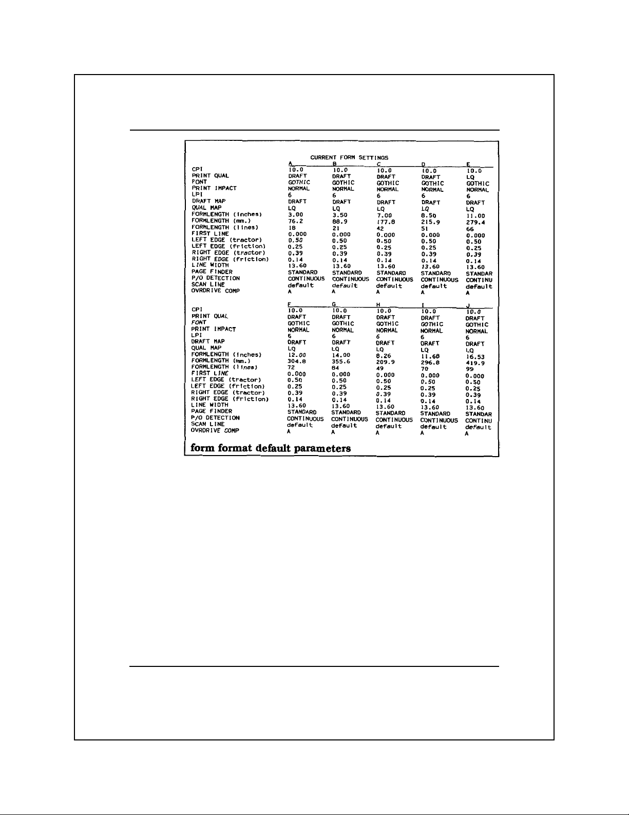
TI Model 880 Printer Emulation 4-16
Page 78

Margin Control Commands
After the margins have been set, changing the line spacing does not
affect the top and bottom margins. However, changing the character
pitch shifts the left margin to the nearest column of the new pitch
value. The right margin shifts in proportion to the change in pitch.
Set Top Margin at Line
Escape sequence: ESC [ N r
Hexadecimal: 1B 5B N 72
N
This command sets the top margin to the line specified by N, where
N can be any value in the range of 1 through the currently selected
form length value. For example, if the currently selected form length
value is 66 lines, N can be any value in the range of 1 through 66
(hexadecimal 31 through 36 36). If N equals 0, the top margin equals
the default value (line 1).
Set Bottom Margin at Line
Escape sequence: ESC [ ; N r
Hexadecimal: 1B 5B 3B N 72
N
This command sets the bottom margin to the line specified by N,
where N can be any value in the range of 1 through the currently
selected form length value. For example, if the currently selected
form length value is 66 lines, N can be any value in the range of 1
through 66 (hexadecimal 31 through 36 36). If N equals 0, the
bottom margin equals the current form length value.
N1
and
Set Top and Bottom Margins at Lines
N2
Escape sequence: ESC [ N1 ; N2 r
Hexadecimal: 1B 5B N1 3B N2 72
This command sets the top and bottom margins to the lines specified
by N1 and N2, respectively, where N1 can be any value in the range
of 1 through the current bottom margin value and N2 can be any
value in the range of 1 through the current form length value. If N1
equals 0, the top margin equals the default value; if N2 equals 0, the
bottom margin equals the default value.
TI Model 880 Printer Emulation 4-17
Page 79

Set Left Margin at Column
Escape sequence: ESC [ N s
Hexadecimal: 1B 5B N 73
N
The variable N can be any value in the range of 1 through, the
column immediately to the left of the current right margin value, as
determined by the line width setting. For example, if the current right
margin is at column 80, the valid range of N is 1 through 79. If N
equals 0, the left margin equals the default value.
Set Right Margin at Column
Escape sequence: ESC [ ; N s
Hexadecimal: 1B 5B 3B N 73
N
The variable N can be any value in the range of the current left margin
value through the value of the right-most column, as determined by
the current line width setting. If N equals 0, the right margin equals
the default value.
N1
and
Set Left and Right Margins at Columns
Escape sequence: ESC [ N1 ; N2 s
Hexadecimal: 1B 5B N1 3B N2 73
N2
This command sets the left and right margins to the columns specified
by N1 and N2, respectively. The N1 and N2 limits are, respectively,
the same as for the Set Left Margin at Column N and the Set Right
Margin at Column N commands.
n
Set Line Width to
Escape sequence: ESC : n
Hexadecimal: 1B 3A n
Columns
The variable n can be any value in the range of 0 through 127 for 7-bits
or 0 through 227 for 8-bits.
Restore Default Line Width
Escape sequence: ESC ;
Hexadecimal: 1B 3B
This command sets the line width to the value currently selected by
the Form Select switch.
TI Model 880 Printer Emulation 4-18
Page 80

Horizontal Motion Commands
After the horizontal tab stops have been set, changing from standard
print to expanded print does not affect the tab stop positions. However,
changing the character pitch alters the tab stop positions in proportion
to the change in pitch.
Backspace
Control character: BS
Hexadecimal: 08
This command causes the printer to move the printhead one space to
the left within the limits of the current left margin.
Tab Horizontally
Control character: HT
Hexadecimal: 09
This command moves the printhead right, to the next tab stop. If no
horizontal tab stops are set between the current logical print position
and the right margin, the printer prints the next character at the first
column of the next line.
Move to Column
Control character: DC4 n
Hexadecimal: 14 n
n
The variable n can be any value within the range of 0 through 255
and within the current line width.
Carriage Return
Control character: CR
Hexadecimal: 0D
If the printer is configured to perform both a line feed and a carriage
return upon receiving CR, the printer prints the current line, and then
performs a line feed and a carriage return. If the printer is not
configured to perform both a line feed and a carriage return upon
receiving CR, the printer prints the current line and moves the logical
print position to the left margin of the current line.
TI Model 880 Printer Emulation 4-19
Page 81

Tab Right to Column
Escape sequence: ESC [ N‘
Hexadecimal: 1B 5B N 60
N
The variable N can represent any column between the current print
position and the currently set right margin position.
N
Tab Right
Escape sequence: ESC [ N a
Hexadecimal: 1B 5B N 61
Columns
For any value of N that exceeds the right margin limit, the printer
performs a line feed and carriage return and prints the next character
in column one of the next line.
Set Horizontal Tab Stops
Escape sequence: ESC [ N1...N16 u
Hexadecimal: 1B 5B N1...N16 75
Escape sequence: ESC 3 n1...n16 NUL
Hexadecimal: 1B 33 n1...n16 00
These commands set up to 16 horizontal tab stops at the columns
specified by N1...N16 or n1...n16. The command ESC 3 n1...n16 NUL
also clears all previously set horizontal tab stops.
The variable N can be any value in the range of column 1 through
column 220. The variable n can be any value in the range of column
1 through 127 for a 7-bits and column 1 through 220 for an 8-bits.
Note: The command ESC 3 n1...n16 is not valid when raster graphics
is enabled.
Clear All Horizontal Tab Stops
Escape sequence: ESC 3 NUL
Hexadecimal: 1B 33 00
Escape sequence: ESC [ 2 g
Hexadecimal: 1B 5B 32 67
TI Model 880 Printer Emulation 4-20
Page 82

Set Horizontal Tab Stop at Current Position
Escape sequence: ESC H
Hexadecimal: 1B 48
Clear Horizontal Tab Stop at Current Position
Escape sequence: ESC [ 0 g
Hexadecimal: 1B 5B 30 67
Vertical Motion Commands
Vertical tab stops define the line numbers at which the paper stops
when performing vertical tab operations. After vertical tab stops
have been set, any change of the vertical pitch causes a proportional
change in the vertical tab stop positions.
Line Feed
Control character: LF
Hexadecimal: 0A
For either of the following conditions, this command causes the
printer to print the current line, advance the paper one print line, and
perform a carriage return.
q The printer is configured to perform a carriage return upon
receiving an LF control character.
q If the printer is not configured to comply with this condition, LF
causes the printer to print the current line and advance the paper
one print line without performing a carriage return.
Form Feed
Control character: FF
Hexadecimal: 0C
This command causes the printer to print the current line, advance
the paper to the first print line of the next form, and position the
printhead at the left margin.
TI Model 880 Printer Emulation 4-21
Page 83

Tab Vertically
Control character: VT
Hexadecimal: 0B
If the printer is configured to perform a carriage return upon receiving
a VT control character, this command causes the printer to print the
current line, advance the paper to the next vertical tab stop, and
perform a carriage return. If the printer is not configured to perform
a carriage return upon receiving VT, the printer prints the current
line and advances the paper to the next vertical tab stop without
performing a carriage return.
Move to Line
Control character: DC2 n
Hexadecimal: 12 n
n
If the printer is configured to perform a carriage return upon receiving
a DC2 control character, this command causes the printer to position
the printhead at the left margin of the print line specified by n. If the
printer is not configured to perform a carriage return upon receiving
DC2, the printer advances the printhead vertically to the specified
print line without performing a carriage return. The variable n can be
any value in the range of 0 through the current form length setting or
through line 113, whichever is less.
Tab Vertically to Line
Escape sequence: ESC [ N d
Hexadecimal: 1B 5B N 64
N
The variable N can be any value in the range of 0 through 113
(hexadecimal 30 through 31 31 33) but must be between the current
print position and the bottom margin.
N
Tab Vertically
Lines
Escape sequence: ESC [ N e
Hexadecimal: 1B 5B N 65
The variable N can be any value in the range of 0 through 113
(hexadecimal 30 through 31 31 33).
TI Model 880 Printer Emulation 4-22
Page 84

Set Vertical Tab Stops
Escape sequence: ESC [ N1...N16 v
Hexadecimal: 1B 5B N1...N16 76
Escape sequence: ESC 1 n1...n16 NUL
Hexadecimal: 1B 31 n1...n16 00
These commands set vertical tab stops at the lines specified by the
variables N1 through N16 or n1 through n16, where each of the
variables N1 through N16 or n1 through n16 can be any value in the
range of 0 through 113. The command ESC 1 n1...n16 NUL also
clears all previously set tab stops.
Set Vertical Tab Stop at Current Position
Escape sequence: ESC J
Hexadecimal: 1B 4A
Clear All Vertical Tab Stops
Escape sequence: ESC [ 4 g
Hexadecimal: 1B 5B 34 67
Clear Vertical Tab Stop at Current Position
Escape sequence: ESC [ 1 g
Hexadecimal: 1B 5B 31 67
Character Pitch Commands
Character pitches of 5, 8.3, 10, 12, and 16.7 characters per inch (cpi)
are available in the Model 880 emulation mode.
Set Character Pitch to 5 cpi
Escape sequence: ESC P I ESC \
Hexadecimal: 1B 50 49 1B 5C
Set Character Pitch to 8.3 cpi
Escape sequence: ESC P J ESC \
Hexadecimal: 1B 50 4A 1B 5C
TI Model 880 Printer Emulation 4-23
Page 85

Set Character Pitch to 10 cpi
Escape sequence: ESC P C ESC \
Hexadecimal: 1B 50 43 1B 5C
Escape sequence: ESC 6
Hexadecimal: 1B 36
Set Character Pitch to 12 cpi
Escape sequence: ESC P K ESC \
Hexadecimal: 1B 50 4B 1B 5C
Set Character Pitch to 16.7 cpi
Escape sequence: ESC P D ESC \
Hexadecimal: 1B 50 44 1B 5C
Escape sequence: ESC 7
Hexadecimal: 1B 37
Line Spacing Commands
The Model 880 emulation mode provides line spacing values of 3, 4,
6, and 8 lpi.
Set Line Spacing to 3 lpi
Escape sequence: ESC P B ESC \
Hexadecimal: 1B 50 42 1B 5C
Set Line Spacing to 4 lpi
Escape sequence: ESC P G ESC \
Hexadecimal: 1B 50 47 1B 5C
Set Line Spacing to 6 lpi
Escape sequence: ESC P A ESC \
Hexadecimal: 1B 50 41 1B 5C
Escape sequence: ESC 4
Hexadecimal: 1B 34
Escape sequence: ESC 2
Hexadecimal: 1B 32
TI Model 880 Printer Emulation 4-24
Page 86

Note: The command ESC 2 is valid only when raster graphics is
enabled.
Set Line Spacing to 8 lpi
Escape sequence: ESC P H ESC \
Hexadecimal: 1B 50 48 1B 5C
Escape sequence: ESC 5
Hexadecimal: 1B 35
Escape sequence: ESC 0
Hexadecimal: 1B 30
Set Line Spacing to n/72 Inch
Escape sequence: ESC A n
Hexadecimal: 1B 41 n
This sequence is valid only if raster graphics is enabled. The valid
range of n is 0 through 85.
N
Set Line Spacing to
Escape sequence: ESC [ N#q
Hexadecimal: 1B 5B N 23 71
/144 Inch
The valid range of N is 0 through 255 (hexadecimal 30 through 32 35
35).
n
Set Line Spacing to
Escape sequence: ESC 3 n
Hexadecimal: 1B 33 n
/216 Inch
This sequence is valid only if raster graphics is enabled. The valid
range of n is 0 through 127 for 7-bits and 0 through 255 for 8-bits.
Select Double Line Spacing
Escape sequence: ESC P S ESC \
Hexadecimal: 1B 50 53 1B 5C
TI Model 880 Printer Emulation 4-25
Page 87

Cancel Double Line Spacing
Escape sequence: ESC P T ESC \
Hexadecimal: 1B 50 54 1B 5C
Print Enhancement Commands
The print enhancement commands enable your printer to improve or
enhance print quality. Print enhancements include expanded and
letter quality print.
Select Expanded (Double-Wide) Print
Escape sequence: ESC P M ESC \
Hexadecimal: 1B 50 4D 1B 5C
Control character: SO
Hexadecimal: 0E
The SO control character functions in this manner only if SO =
EXPAND is entered from the control panel (set to ON).
Cancel Expanded (Double-Wide) Print
Escape sequence: ESC P N ESC \
Hexadecimal: 1B 50 4E 1B 5C
Select Letter-Quality Print
Escape sequence: ESC P O ESC \
Hexadecimal: 1B 50 4F 1B 5C
Cancel Letter-Quality Print
Escape sequence: ESC P P ESC \
Hexadecimal: 1B 50 50 1B 5C
TI Model 880 Printer Emulation 4-26
Page 88

Raster Graphics Commands
In the Model 880 raster graphics mode, the printer alternates between
the left and right printhead pins and uses only the top eight pins of
each column. The graphics feature enables you to create drawings by
sending dot patterns (in the form of hexadecimal codes) to the printer.
When the printer receives a hexadecimal code from the host computer,
it maps the individual code bits to the individual printhead pins.
Set Up Graphics Parameters
Escape sequence: ESC [ H ; B ; V q
Hexadecimal: 1B 5B H 3B B 5B V 71
This command sets the horizontal dot density (H) and the vertical
line spacing (V) and specifies the number of hexadecimal code bytes
(B) to print. The variables H, V, and B are as follows.
q Horizontal dot density (H) — 60, 72, 120, or 144 dpi. The default
value is 60 dpi. If the horizontal dot density is omitted, the
printer defaults to the last value selected since the last power-up
operation.
q Number of hexadecimal code bytes (B) to print — can be set to
any value in the range of 0 to 1958 (for a line width of 13.6
inches and a horizontal dot density of 144 dpi). If this parameter
is omitted or set to 0, the printer prints no raster graphics.
q Vertical line spacing (V) — N/144 inch, where the range of N is
0 through 255. A value of 0 indicates that no line feed operation
is to occur.
TI Model 880 Printer Emulation 4-27
Page 89

Select 60 dpi Graphics
Escape sequence: ESC K n1 n2
Hexadecimal: 1B 4B n1 n2
The variables n1 and n2 specify the number of bytes to print.
Use the following steps to find the values of n1 and n2 for a horizontal
line of graphics of a given length in inches.
1. Multiply by 60 the length of the line (in inches) to be printed.
This operation yields the number of bytes (n) required at 60 dots
per inch.
2. Divide the number of bytes by 256 (n/256); the quotient and the
remainder of n/256 are, respectively, the decimal values of n2
and n1.
3. Convert the decimal values of n2 and n1 obtained in step 1 to
their hexadecimal equivalents.
Note: This procedure can be applied to any of the graphics selection
commands in this chapter as well as those in Chapters 5 through 8.
Select 120 dpi Graphics
Escape sequence: ESC L n1 n2
Hexadecimal: 1B 4C n1 n2
The variables n1 and n2 specify the number of bytes to print. Modify
the procedure described for the Select 60 dpi Graphics command to
determine the values of n1 and n2. In step 1 of this procedure,
multiply the line length by 120 instead of 60 to determine the
number of bytes required.
Note: ESC K nl n2 and ESC L nl n2 are valid only when raster
graphics is enabled.
TI Model 880 Printer Emulation 4-28
Page 90

Font Selection Commands
Select Font
Escape sequence: ESC f N
Hexadecimal: 1B 66 N
N
The printer can have a maximum of 10 fonts, including the two
standard fonts (Gothic and Courier) and up to eight optional fonts.
The variable N can be any value in the range of 0 through 9, where 0
designates Gothic, 1 designates Courier, 2 designates the first font in
option ROM 1, 3 designates the second font in option ROM 1, and
so on. The range of N for either option ROM depends upon the
number of fonts contained in each ROM.
Examples. If option ROM 1 has two fonts and option ROM 2 has
three fonts, then the range of N is 2 through 3 for option ROM 1 and
4 through 7 for option ROM 2. If option ROM 1 has four fonts and
option ROM 2 has three fonts, then the range of N is 2 through 5 for
option ROM 1 and 6 through 8 for option ROM 2.
Font Invocation
The Model 880 Printer emulation enables you to define the contents
of the “in-use” font table. The in-use table defines the font currently
being printed. The contents of the in-use table can be replaced
entirely by an alternate font, or individual characters in the in-use
table can be replaced by individual characters invoked from an
alternate font. There are four possible alternate sets, called G0, G1,
G2, and G3.
Designate G0 Font by ROM Identifier
Escape sequence: ESC ( N
Hexadecimal: 1B 28 N
Designate G1 Font by ROM Identifier
Escape sequence: ESC ) N
Hexadecimal: 1B 29 N
TI Model 880 Printer Emulation 4-29
N
N
Page 91

Designate G2 Font by ROM Identifier
Escape sequence: ESC * N
Hexadecimal: 1B 2A N
N
Designate G3 Font by ROM Identifier
Escape sequence: ESC + N
Hexadecimal: 1B 2B N
N
Valid values for N are G for Gothic and C for Courier.
Select Designated Character From G2 Font
Control Character: EM N
Hexadecimal: 19 N
Select Designated Character From G3 Font
Control Character: GS N
Hexadecimal: 1D N
Valid values for N are any font character.
Invoke G0 Font as GL
Control Character: SI
Hexadecimal: 1F
Invoke G1 Font as GL
Control Character: SO
Hexadecimal: 1E
Note: You must set SO to Expand OFF using the control panel
before using this command.
Invoke G2 Font as GL
Escape sequence: ESC n
Hexadecimal: 1B 6E
Invoke G3 Font as GL
Escape sequence: ESC o
Hexadecimal: 1B 6F
TI Model 880 Printer Emulation 4-30
Page 92

Invoke G1 Font as GR
Escape sequence: ESC k
Hexadecimal: 1B 6B
Invoke G2 Font as GR
Escape sequence: ESC 1
Hexadecimal: 1B 6C
Invoke G3 Font as GR
Escape sequence: ESC m
Hexadecimal: 1B 6D
TI Model 880 Printer Emulation 4-31
Page 93

5
Texas Instruments
Model 855 Printer WP Emulation
Introduction .................................................................................... 5-4
Motion Indexes ............................................................................... 5-5
Model 855 WP Commands............................................................. 5-6
Model 855 WP Command Descriptions......................................... 5-9
Printer Operation Commands .................................................... 5-9
Select DP Mode .................................................................... 5-9
Select WP Mode ................................................................... 5-9
Suspend Printing................................................................... 5-9
Select Unidirectional Printing ............................................ 5-10
Cancel Unidirectional Printing ........................................... 5-10
Select Reverse Printing....................................................... 5-10
Cancel Reverse Printing ..................................................... 5-10
Set Most Significant Bit ..................................................... 5-10
Reset Most Significant Bit.................................................. 5-10
Form Format and Font Selection Commands .......................... 5-11
Set Form Length to nl n2 Lines .......................................... 5-11
Select Font n ....................................................................... 5-12
Margin Control Commands ..................................................... 5-12
Select Right Margin Justification ....................................... 5-12
Cancel Right Margin Justification...................................... 5-13
Set Top Margin at Current Position ....................................5-13
Set Bottom Margin at Current Position .............................. 5-13
Set Left Margin at Current Position ................................... 5-13
Set Right Margin at Current Position ................................. 5-13
Horizontal Motion Commands ................................................ 5-14
Backspace ........................................................................... 5-14
Tab Horizontally ................................................................. 5-14
Carriage Return................................................................... 5-14
Move Back 1/120 Inch........................................................ 5-15
TI Model 855 Printer WP Emulation 5-1
Page 94

Tab Horizontally Absolute.................................................. 5-15
Set Horizontal Tab Stop at Current Position ...................... 5-15
Clear All Horizontal Tab Stops .......................................... 5-15
Clear Horizontal Tab Stop at Current Position ................... 5-15
Vertical Motion Commands..................................................... 5-16
Line Feed ............................................................................ 5-16
Form Feed ........................................................................... 5-16
Tab Vertically...................................................................... 5-16
Tab Vertically Absolute ...................................................... 5-16
Move Up One Line ............................................................. 5-17
Move Up One-Half Line..................................................... 5-17
Move Down One-Half Line................................................ 5-17
Character Pitch Commands ..................................................... 5-17
Set Horizontal Motion Index to (n-l)/120 Inch................... 5-17
Set Character Pitch to 10 cpi .............................................. 5-17
Set Character Pitch to 12 cpi .............................................. 5-18
Line Spacing Commands ......................................................... 5-18
Set Vertical Motion Index to (n-l)/48 Inch ......................... 5-18
Set Vertical Motion Index to (n-l)/144 Inch ....................... 5-18
Character Set Commands ........................................................ 5-18
Print Special Character ....................................................... 5-18
Print Enhancement Commands................................................ 5-19
Select Expanded Print......................................................... 5-19
Cancel Expanded Print ....................................................... 5-19
Select Compressed Print ..................................................... 5-19
Cancel Compressed Print.................................................... 5-19
Select Letter-Quality Print.................................................. 5-19
Cancel Letter-Quality Print ................................................ 5-20
Select Text-Underline Print ................................................ 5-20
Cancel Text-Underline Print ............................................... 5-20
Select Boldface Print .......................................................... 5-20
Cancel Boldface Print ......................................................... 5-20
Select Shadow Print............................................................ 5-20
Cancel Shadow Print .......................................................... 5-20
Raster Graphics Commands .................................................... 5-21
TI Model 855 Printer WP Emulation 5-2
Page 95

Select 60 dpi Graphics ........................................................ 5-21
Select 72 dpi Graphics ........................................................ 5-21
Select 120 dpi Graphics ...................................................... 5-21
Select 144 dpi Graphics ...................................................... 5-21
TI Model 855 Printer WP Emulation 5-3
Page 96

Introduction
This chapter describes the Texas Instruments Model 855 word
processing (WP) emulation mode. The Model 855 WP emulation
mode allows the Model 8900 Series Printer to accept and respond to
commands similar to those for a daisy-wheel printer. This mode
allows the printer to emulate most functions of the Model 855 Printer
operating in its WP mode with the following considerations.
q The Model 855 WP emulation supports all Model 8900 global
commands.
q You can select ribbon color with the command sequence ESC c n
or ESC r n.
q Factory selected power-up defaults for the Model 855 WP
emulation are:
— Processing mode — DP (The WP mode must be selected
after power-up.)
— Auto LF — NO
— The last form setting change made via the control panel is
retained and restored at power-up.
q The Model 855 WP emulation uses standard pitch and point for
superscript and subscript characters.
q The standard character set is the IBM PC2 Character Set.
q The escape sequence to select mosaic graphics by setting the
MSDB to 1 is ESC v.
q The escape sequence to cancel mosaic graphics by setting the
MSDB to 1 is ESC =.
TI Model 855 Printer WP Emulation 5-4
Page 97

q The escape sequence for font selection is ESC f N.
q Selecting or canceling proportional spacing is not supported.
q Disabling the paper-out detection is not supported.
Motion Indexes
The Model 855 WP emulation mode uses motion indexes to specify
certain horizontal and vertical parameters. These motion indexes are
established by character pitch and line spacing commands described
later in this chapter.
The horizontal motion index and vertical motion index are abbreviated,
respectively, as HMI and VMI. Their definitions are as follows.
q HMI — The horizontal distance between two adjacent characters.
The HMI range is 0 through 254/120 (0 through 2.12) inches in
increments of 1/120 inch.
q VMI — The vertical distance between two adjacent print lines.
The VMI range can be either of the following, depending upon
the escape sequence used to establish the VMI.
— 0 through 84/48 (0 through 1.75) inches in increments of
1/48 inch
— 0 through 254/144 (0 through 1.62) inches in increments of
1/144 inch
TI Model 855 Printer WP Emulation 5-5
Page 98
Model 855 WP Commands
The following table lists the Model 855 WP commands. The paragraphs that follow the table describe these commands.
Model 855 WP Commands
Command Command Name
Printer Operation
ESC @ Select DP Mode
ESC CR P Select WP Mode
ESC SUB I Select WP Mode
ESC w Suspend Printing
ESC > Select Unidirectional Printing
ESC < Cancel Unidirectional Printing
ESC 6 Select Reverse Printing
ESC 5 Cancel Reverse Printing
ESC v Set Most Significant Bit
ESC = Reset Most Significant Bit
Form Format and Font Selection
ESC F n1 n2 Set Form Length to n1 n2 Lines
ESC f n Select Font n
Margin Control
ESC ] Select Right Margin Justification
ESC [ Cancel Right Margin Justification
ESC + Set Top Margin at Current Position
ESC - Set Bottom Margin at Current Position
ESC 9 Set Left Margin at Current Position
ESC 0 Set Right Margin at Current Position
TI Model 855 Printer WP Emulation 5-6
Page 99

Model 855 WP Commands (continued)
Command Name Command Name
Horizontal Motion
BS Backspace
HT Tab Horizontally
CR Carriage Return
ESC BS Move Back 1/120 Inch
ESC HT n Tab Horizontally Absolute
ESC 1 Set Horizontal Tab Stop at Current Position
ESC 2 Clear All Horizontal Tab Stops
ESC 8 Clear Horizontal Tab Stops at Current Position
Vertical Motion
LF Line Feed
FF Form Feed
VT Tab Vertically
ESC VT n Tab Vertically Absolute
ESC LF Move Up One Line
ESC D Move Up One-Half Line
ESC U Move Down One-Half Line
Character Pitch
ESC US n Set Horizontal Motion Index to (n-1)/120 Inch
ESC y Set Character Pitch to 10 cpi
ESC z Set Character Pitch to 12 cpi
Line Spacing
ESC RS n Set Vertical Motion Index to (n-l)/48 Inch
ESC FS n Set Vertical Motion Index to (n-1)/144 Inch
TI Model 855 Printer WP Emulation 5-7
Page 100

Model 855 WP Commands (concluded)
Command Name Command Name
Horizontal Motion
ESC SP Print Special Character
ESC / Print Special Character
Print Enhancement
SO Select Expanded Print
DC4 Cancel Expanded Print
SI Select Compressed Print
DC2 Cancel Compressed Print
ESC q Select Letter-Quality Print
ESC e Select Letter-Quality Print
ESC d Cancel Letter-Quality Print
ESC I Select Text-Underline Print
ESC J Cancel Text-Underline Print
ESC K n Select Boldface Print
ESC M Cancel Boldface Print
ESC Q Select Shadow Print
ESC R Cancel Shadow Print
Raster Graphics
ESC k n1 n2 Select 60 dpi Graphics
ESC n n1 r2 Select 72 dpi Graphics
ESC j n1 n2 Select 120 dpi Graphics
ESC o n1 n2 Select 144 dpi Graphics
TI Model 855 Printer WP Emulation 5-8
 Loading...